EP3444025A1 - Mischanlage und entsprechendes mischverfahren - Google Patents
Mischanlage und entsprechendes mischverfahren Download PDFInfo
- Publication number
- EP3444025A1 EP3444025A1 EP18185088.4A EP18185088A EP3444025A1 EP 3444025 A1 EP3444025 A1 EP 3444025A1 EP 18185088 A EP18185088 A EP 18185088A EP 3444025 A1 EP3444025 A1 EP 3444025A1
- Authority
- EP
- European Patent Office
- Prior art keywords
- metering
- metering cylinder
- components
- cylinder
- mixing
- Prior art date
- Legal status (The legal status is an assumption and is not a legal conclusion. Google has not performed a legal analysis and makes no representation as to the accuracy of the status listed.)
- Granted
Links
Images




Classifications
-
- F—MECHANICAL ENGINEERING; LIGHTING; HEATING; WEAPONS; BLASTING
- F04—POSITIVE - DISPLACEMENT MACHINES FOR LIQUIDS; PUMPS FOR LIQUIDS OR ELASTIC FLUIDS
- F04B—POSITIVE-DISPLACEMENT MACHINES FOR LIQUIDS; PUMPS
- F04B9/00—Piston machines or pumps characterised by the driving or driven means to or from their working members
- F04B9/02—Piston machines or pumps characterised by the driving or driven means to or from their working members the means being mechanical
-
- B—PERFORMING OPERATIONS; TRANSPORTING
- B01—PHYSICAL OR CHEMICAL PROCESSES OR APPARATUS IN GENERAL
- B01F—MIXING, e.g. DISSOLVING, EMULSIFYING OR DISPERSING
- B01F25/00—Flow mixers; Mixers for falling materials, e.g. solid particles
- B01F25/40—Static mixers
- B01F25/42—Static mixers in which the mixing is affected by moving the components jointly in changing directions, e.g. in tubes provided with baffles or obstructions
- B01F25/43—Mixing tubes, e.g. wherein the material is moved in a radial or partly reversed direction
- B01F25/431—Straight mixing tubes with baffles or obstructions that do not cause substantial pressure drop; Baffles therefor
-
- B—PERFORMING OPERATIONS; TRANSPORTING
- B01—PHYSICAL OR CHEMICAL PROCESSES OR APPARATUS IN GENERAL
- B01F—MIXING, e.g. DISSOLVING, EMULSIFYING OR DISPERSING
- B01F25/00—Flow mixers; Mixers for falling materials, e.g. solid particles
- B01F25/60—Pump mixers, i.e. mixing within a pump
-
- B—PERFORMING OPERATIONS; TRANSPORTING
- B01—PHYSICAL OR CHEMICAL PROCESSES OR APPARATUS IN GENERAL
- B01F—MIXING, e.g. DISSOLVING, EMULSIFYING OR DISPERSING
- B01F33/00—Other mixers; Mixing plants; Combinations of mixers
- B01F33/80—Mixing plants; Combinations of mixers
- B01F33/81—Combinations of similar mixers, e.g. with rotary stirring devices in two or more receptacles
- B01F33/811—Combinations of similar mixers, e.g. with rotary stirring devices in two or more receptacles in two or more consecutive, i.e. successive, mixing receptacles or being consecutively arranged
-
- B—PERFORMING OPERATIONS; TRANSPORTING
- B01—PHYSICAL OR CHEMICAL PROCESSES OR APPARATUS IN GENERAL
- B01F—MIXING, e.g. DISSOLVING, EMULSIFYING OR DISPERSING
- B01F33/00—Other mixers; Mixing plants; Combinations of mixers
- B01F33/80—Mixing plants; Combinations of mixers
- B01F33/82—Combinations of dissimilar mixers
- B01F33/821—Combinations of dissimilar mixers with consecutive receptacles
-
- B—PERFORMING OPERATIONS; TRANSPORTING
- B01—PHYSICAL OR CHEMICAL PROCESSES OR APPARATUS IN GENERAL
- B01F—MIXING, e.g. DISSOLVING, EMULSIFYING OR DISPERSING
- B01F35/00—Accessories for mixers; Auxiliary operations or auxiliary devices; Parts or details of general application
- B01F35/10—Maintenance of mixers
- B01F35/145—Washing or cleaning mixers not provided for in other groups in this subclass; Inhibiting build-up of material on machine parts using other means
- B01F35/1452—Washing or cleaning mixers not provided for in other groups in this subclass; Inhibiting build-up of material on machine parts using other means using fluids
-
- B—PERFORMING OPERATIONS; TRANSPORTING
- B01—PHYSICAL OR CHEMICAL PROCESSES OR APPARATUS IN GENERAL
- B01F—MIXING, e.g. DISSOLVING, EMULSIFYING OR DISPERSING
- B01F35/00—Accessories for mixers; Auxiliary operations or auxiliary devices; Parts or details of general application
- B01F35/80—Forming a predetermined ratio of the substances to be mixed
- B01F35/88—Forming a predetermined ratio of the substances to be mixed by feeding the materials batchwise
- B01F35/882—Forming a predetermined ratio of the substances to be mixed by feeding the materials batchwise using measuring chambers, e.g. volumetric pumps, for feeding the substances
- B01F35/8821—Forming a predetermined ratio of the substances to be mixed by feeding the materials batchwise using measuring chambers, e.g. volumetric pumps, for feeding the substances involving controlling
-
- B—PERFORMING OPERATIONS; TRANSPORTING
- B01—PHYSICAL OR CHEMICAL PROCESSES OR APPARATUS IN GENERAL
- B01F—MIXING, e.g. DISSOLVING, EMULSIFYING OR DISPERSING
- B01F35/00—Accessories for mixers; Auxiliary operations or auxiliary devices; Parts or details of general application
- B01F35/80—Forming a predetermined ratio of the substances to be mixed
- B01F35/88—Forming a predetermined ratio of the substances to be mixed by feeding the materials batchwise
- B01F35/882—Forming a predetermined ratio of the substances to be mixed by feeding the materials batchwise using measuring chambers, e.g. volumetric pumps, for feeding the substances
- B01F35/8822—Forming a predetermined ratio of the substances to be mixed by feeding the materials batchwise using measuring chambers, e.g. volumetric pumps, for feeding the substances using measuring chambers of the piston or plunger type
-
- B—PERFORMING OPERATIONS; TRANSPORTING
- B05—SPRAYING OR ATOMISING IN GENERAL; APPLYING FLUENT MATERIALS TO SURFACES, IN GENERAL
- B05B—SPRAYING APPARATUS; ATOMISING APPARATUS; NOZZLES
- B05B12/00—Arrangements for controlling delivery; Arrangements for controlling the spray area
- B05B12/14—Arrangements for controlling delivery; Arrangements for controlling the spray area for supplying a selected one of a plurality of liquids or other fluent materials or several in selected proportions to a spray apparatus, e.g. to a single spray outlet
- B05B12/1418—Arrangements for controlling delivery; Arrangements for controlling the spray area for supplying a selected one of a plurality of liquids or other fluent materials or several in selected proportions to a spray apparatus, e.g. to a single spray outlet for supplying several liquids or other fluent materials in selected proportions to a single spray outlet
-
- F—MECHANICAL ENGINEERING; LIGHTING; HEATING; WEAPONS; BLASTING
- F04—POSITIVE - DISPLACEMENT MACHINES FOR LIQUIDS; PUMPS FOR LIQUIDS OR ELASTIC FLUIDS
- F04B—POSITIVE-DISPLACEMENT MACHINES FOR LIQUIDS; PUMPS
- F04B13/00—Pumps specially modified to deliver fixed or variable measured quantities
- F04B13/02—Pumps specially modified to deliver fixed or variable measured quantities of two or more fluids at the same time
-
- F—MECHANICAL ENGINEERING; LIGHTING; HEATING; WEAPONS; BLASTING
- F04—POSITIVE - DISPLACEMENT MACHINES FOR LIQUIDS; PUMPS FOR LIQUIDS OR ELASTIC FLUIDS
- F04B—POSITIVE-DISPLACEMENT MACHINES FOR LIQUIDS; PUMPS
- F04B17/00—Pumps characterised by combination with, or adaptation to, specific driving engines or motors
- F04B17/03—Pumps characterised by combination with, or adaptation to, specific driving engines or motors driven by electric motors
-
- F—MECHANICAL ENGINEERING; LIGHTING; HEATING; WEAPONS; BLASTING
- F04—POSITIVE - DISPLACEMENT MACHINES FOR LIQUIDS; PUMPS FOR LIQUIDS OR ELASTIC FLUIDS
- F04B—POSITIVE-DISPLACEMENT MACHINES FOR LIQUIDS; PUMPS
- F04B23/00—Pumping installations or systems
- F04B23/04—Combinations of two or more pumps
- F04B23/06—Combinations of two or more pumps the pumps being all of reciprocating positive-displacement type
-
- F—MECHANICAL ENGINEERING; LIGHTING; HEATING; WEAPONS; BLASTING
- F04—POSITIVE - DISPLACEMENT MACHINES FOR LIQUIDS; PUMPS FOR LIQUIDS OR ELASTIC FLUIDS
- F04B—POSITIVE-DISPLACEMENT MACHINES FOR LIQUIDS; PUMPS
- F04B49/00—Control, e.g. of pump delivery, or pump pressure of, or safety measures for, machines, pumps, or pumping installations, not otherwise provided for, or of interest apart from, groups F04B1/00 - F04B47/00
- F04B49/06—Control using electricity
-
- F—MECHANICAL ENGINEERING; LIGHTING; HEATING; WEAPONS; BLASTING
- F04—POSITIVE - DISPLACEMENT MACHINES FOR LIQUIDS; PUMPS FOR LIQUIDS OR ELASTIC FLUIDS
- F04B—POSITIVE-DISPLACEMENT MACHINES FOR LIQUIDS; PUMPS
- F04B49/00—Control, e.g. of pump delivery, or pump pressure of, or safety measures for, machines, pumps, or pumping installations, not otherwise provided for, or of interest apart from, groups F04B1/00 - F04B47/00
- F04B49/22—Control, e.g. of pump delivery, or pump pressure of, or safety measures for, machines, pumps, or pumping installations, not otherwise provided for, or of interest apart from, groups F04B1/00 - F04B47/00 by means of valves
-
- B—PERFORMING OPERATIONS; TRANSPORTING
- B05—SPRAYING OR ATOMISING IN GENERAL; APPLYING FLUENT MATERIALS TO SURFACES, IN GENERAL
- B05B—SPRAYING APPARATUS; ATOMISING APPARATUS; NOZZLES
- B05B15/00—Details of spraying plant or spraying apparatus not otherwise provided for; Accessories
- B05B15/50—Arrangements for cleaning; Arrangements for preventing deposits, drying-out or blockage; Arrangements for detecting improper discharge caused by the presence of foreign matter
- B05B15/55—Arrangements for cleaning; Arrangements for preventing deposits, drying-out or blockage; Arrangements for detecting improper discharge caused by the presence of foreign matter using cleaning fluids
-
- B—PERFORMING OPERATIONS; TRANSPORTING
- B05—SPRAYING OR ATOMISING IN GENERAL; APPLYING FLUENT MATERIALS TO SURFACES, IN GENERAL
- B05B—SPRAYING APPARATUS; ATOMISING APPARATUS; NOZZLES
- B05B15/00—Details of spraying plant or spraying apparatus not otherwise provided for; Accessories
- B05B15/50—Arrangements for cleaning; Arrangements for preventing deposits, drying-out or blockage; Arrangements for detecting improper discharge caused by the presence of foreign matter
- B05B15/58—Arrangements for cleaning; Arrangements for preventing deposits, drying-out or blockage; Arrangements for detecting improper discharge caused by the presence of foreign matter preventing deposits, drying-out or blockage by recirculating the fluid to be sprayed from upstream of the discharge opening back to the supplying means
-
- F—MECHANICAL ENGINEERING; LIGHTING; HEATING; WEAPONS; BLASTING
- F04—POSITIVE - DISPLACEMENT MACHINES FOR LIQUIDS; PUMPS FOR LIQUIDS OR ELASTIC FLUIDS
- F04B—POSITIVE-DISPLACEMENT MACHINES FOR LIQUIDS; PUMPS
- F04B2201/00—Pump parameters
- F04B2201/12—Parameters of driving or driven means
- F04B2201/1208—Angular position of the shaft
Definitions
- the invention relates to a mixing plant for mixing a plurality of components (e.g., coating agent components) in a given mixing ratio into a mixture (e.g., coating agent mixture), for example, for mixing plastics or blending a masterbatch with a hardener to form a two-component paint.
- a mixing plant for mixing a plurality of components (e.g., coating agent components) in a given mixing ratio into a mixture (e.g., coating agent mixture), for example, for mixing plastics or blending a masterbatch with a hardener to form a two-component paint.
- injection mixing systems are known in which a continuous stream of a first coating agent component is continuously measured. Upon reaching a certain minimum quantity of the coating agent component, a certain injection quantity of a second coating agent component is then injected into the stream. This process is then repeated continuously, so that the two coating agent components are combined with the desired mixing ratio.
- injection mixing systems usually still require a static mixer in order to mix the coating composition more uniformly.
- metering pump systems are known for mixing different coating agent components, in which metering pumps bring the various coating agent components together in a common channel, wherein the coating agent mixture is then usually passed through a static mixer in order to mix the coating agent components more uniformly.
- the mixing ratio is adjusted by the flow rates of the metering pumps.
- a modification of such metering pump systems are metering piston systems in which metering cylinders with displaceable metering pistons occur instead of metering pumps.
- mixing chamber systems are known in which the individual coating agent components are introduced, for example, by metering pumps or dosing into a mixing chamber and mixed there, for example, by a stirrer.
- a mixing chamber system is for example out EP 0 334 092 A1 known.
- a mixing device which can be integrated into a nebulizer.
- a shuttle valve arrangement selects the coating agent components to be mixed and brings them together at the outlet of the shuttle valve arrangement, wherein the coating agent mixture is then passed through a static mixer (eg lattice mixer, spiral mixer).
- the invention is therefore based on the object to provide an improved mixing plant or a corresponding mixing method.
- the mixing plant according to the invention is suitable for mixing a plurality of coating agent components in a predetermined mixing ratio to form a coating agent mixture.
- the mixing plant according to the invention can be used to mix a master paint with a hardener to form a two-component paint.
- the invention is not based on the type of the coating composition components to be mixed and hardener limited. Rather, the invention is also suitable for mixing other types of coating agent components. It should also be mentioned that the invention is not limited to exactly two coating agent components with regard to the number of coating agent components to be mixed. Rather, the invention is also suitable for mixing a larger number of coating agent components.
- the invention is also suitable for mixing other components than coating agent components.
- the components to be mixed may be plastics.
- milky plastisols in the toy industry can be colored by mixing base color pigments to achieve the desired hue.
- adhesives that are colored to avoid certain color contrasts in joints of edges.
- coating agent components for the sake of simplicity, the concrete term "coating agent components" is used, but this is not intended to be limiting.
- the mixing plant according to the invention initially according to the prior art according to DE 10 2015 008 659 A1 a shuttle valve assembly having a plurality of inlets for supplying the coating agent components to be mixed and a common outlet for dispensing the coating agent components to be mixed.
- the shuttle valve assembly not only serves to control the material flow for the individual coating agent components, but also to select the coating agent components to be mixed from a variety of available coating agent components.
- the shuttle valve assembly selects one of numerous master paints and merges with a common or an individually suitable hardener.
- the shuttle valve assembly preferably sequentially dispenses the coating agent components to be mixed at the outlet, i. without a temporal overlap. At the outlet of the shuttle valve arrangement so preferably no coating agent mixture is dispensed. Rather, the coating agent components to be mixed at the outlet of the shuttle valve arrangement preferably emerge sequentially and unmixed.
- the mixing plant according to the invention is now characterized by a metering cylinder which is connected to the outlet of the shuttle valve arrangement and the coating agent components to be mixed receives from the shuttle valve assembly.
- a metering cylinder which is connected to the outlet of the shuttle valve arrangement and the coating agent components to be mixed receives from the shuttle valve assembly.
- a displaceable metering piston which is displaced during filling of the metering cylinder, so that the piston movement of the metering piston defines the filling amount of the respective coating agent component.
- the coating agent components to be mixed are thus selected by the shuttle valve arrangement, supplied to the metering cylinder and combined in the metering cylinder.
- a metering cylinder with an exactly circular inner cross section. Rather, the dosing and the metering can also have any other cross-sections. All that matters is that the metering piston is displaceable in the metering cylinder in order to define the filling quantity of the respective coating agent.
- a metering drive is provided to move the metering piston in the metering cylinder according to the defined filling quantity of the respective coating agent.
- the term of a metering cylinder used in the context of the invention preferably implies that the respective filling quantity of the respective coating agent component can be precisely adjusted, which corresponds to the term metering.
- the metering drive comprises an electric motor (e.g., servomotor) which can act on the metering piston via a helical gear (e.g., ball screw gear) or via a toothed belt.
- an electric motor e.g., servomotor
- a helical gear e.g., ball screw gear
- the metering drive has a rotary encoder which measures the angle of rotation of the electric motor, wherein the angle of rotation of the electric motor also defines the filling quantity.
- the rotary encoder thus indirectly enables an accurate measurement of the filling quantity of the respective coating agent component. Therefore, the rotary encoder preferably has a very large angular resolution in order to achieve a high dosing accuracy.
- the angular resolution of the rotary encoder can therefore be in the invention at least 2000, 4000, 8000, 16000, 32000, 64000 or even at least 128,000 increments per revolution in order to achieve a correspondingly high dosing accuracy.
- the dosing drive preferably allows - as already briefly mentioned above - a high dosing accuracy with very low Dosiersavingn.
- dosing errors may be less than ⁇ 10ml, ⁇ 5ml, ⁇ 2ml, ⁇ 1ml, ⁇ 500n1, ⁇ 200nl or even ⁇ 100nl.
- the metering drive operates pneumatically or hydraulically.
- the metering cylinder is connected to the outlet of the shuttle valve assembly, i. the metering cylinder is filled from the outlet of the shuttle valve assembly.
- a controllable shut-off valve is arranged between the outlet of the shuttle valve assembly and the metering cylinder to control the material delivery from the shuttle valve assembly into the metering cylinder.
- the metering cylinder then delivers the premixed coating agent mixture to an application device, wherein a controllable outlet valve and / or a static mixer (eg lattice mixer, spiral mixer) can be arranged between the metering cylinder and the application device, the static mixer having the task of removing from the metering cylinder Mix only premixed coating agent components more evenly.
- a controllable outlet valve and / or a static mixer eg lattice mixer, spiral mixer
- the mixing plant according to the invention can have a material return in order to receive coating agent residues from the metering cylinder during a flushing process.
- this material recycling can have a collecting container for the coating agent residues.
- a controllable flushing agent valve is preferably provided in order to control the supply of flushing agent into the metering cylinder.
- a controllable return valve may be provided to control the discharge of material from the metering cylinder in the material recirculation.
- metering cylinders are arranged one behind the other in the flow direction, which also enables potential separation.
- the individual metering cylinders are preferably each assigned a flushing agent valve, a return valve, a shut-off valve and / or an outlet valve.
- the connection of the material recirculation can take place differently with the different metering cylinders.
- the material return can be connected to the associated return valve in the upstream metering directly to the metering cylinder.
- the static mixer can be arranged between metering cylinder and material return.
- the mixing plant according to the invention is suitable for a very large viscosity range, i. Coating agent components with very different viscosities can be mixed.
- the viscosity bandwidth may be 15MPa ⁇ s to 10000MPa ⁇ s.
- the invention also claims protection for a corresponding mixing process, wherein the individual process steps of the mixing process according to the invention already emerge from the description and therefore need not be described separately.
- the reciprocating movement of the metering piston can be achieved, for example, by filling a residual volume of air into the metering cylinder in addition to the coating agent components or the flushing agent to be mixed.
- the metering drive is then turned on to compress the air in the metering cylinder.
- the metering piston is then released, so that the compressed air can jump back the metering piston in a jerky manner, as a result of which turbulence is created in the metering cylinder, which improves efficiency the measurement or to dissolve the coating residues in the dosing contribute.
- the air can then be drained from the dosing cylinder, for example.
- the various coating agent components to be mixed are preferably introduced into the metering cylinder in a specific sequence.
- the order of filling of the metering cylinder can be based on the viscosity of the coating agent components to be filled.
- the filling of low-viscosity coating agent components is started in this case, in order then to proceed with the filling of higher-viscosity coating agent components.
- the order of filling of the various coating agent components is oriented to the respective filling amount, preferably starting with a filling of small quantities and continued with a filling of large quantities.
- FIG. 1 shows an embodiment of a mixing plant according to the invention for mixing a plurality of coating agent components (eg hardener and various masterbatches) to a coating agent mixture, which then from an application device 1 (eg atomizer) on a component (eg motor vehicle body component) can be applied.
- a coating agent component eg hardener and various masterbatches
- an application device 1 eg atomizer
- a component eg motor vehicle body component
- the mixing plant according to the invention initially has a shuttle valve arrangement 2 with numerous inlets 3 in order to supply the coating agent components to be mixed.
- a shuttle valve arrangement 2 with numerous inlets 3 in order to supply the coating agent components to be mixed.
- several different basecoats and a hardener can be supplied via the inlets 3 of the shuttle valve assembly 2.
- the individual inlets 3 of the shuttle valve arrangement 2 are each assigned an inlet valve 4 in order to control the material flow from the individual inlets 3 into a common channel 5 to an outlet 6 of the shuttle valve arrangement 2.
- the outlet 6 of the shuttle valve assembly 2 is connected via a shut-off valve 7 with a metering cylinder 8.
- a metering piston 9 is displaceable by a metering drive 10 with a servomotor, wherein the metering drive 10 acts on the metering piston 9 via an electrically insulating piston rod 11.
- the electrically insulating piston rod 11 in this case enables potential separation in the context of an electrostatic coating agent charging.
- the metering cylinder 8 is connected to the application device 1 via an outlet valve 12, a static mixer 13 (e.g., lattice mixer, spiral mixer) and a main valve 14.
- a static mixer 13 e.g., lattice mixer, spiral mixer
- the mixing plant still has a flushing valve 15 in order to introduce flushing agent into the metering cylinder 8 during a flushing process.
- the mixing plant comprises a material return 16, which opens into a collecting container 17.
- controllable return valve 18 is arranged to control the discharge of material from the metering cylinder 8 in the collecting container 17.
- a first step S1 the metering piston 9 is moved to a discharge position, i. in the drawing in the upper position. Furthermore, the flushing valve 15, the return valve 18 and the outlet valve 12 are closed while the shut-off valve 7 between the shuttle valve assembly 2 and the metering cylinder 8 is opened.
- a step S2 the desired inlet valve 4 is then opened, wherein initially a low-viscosity coating agent component A is selected.
- a next step S3 the metering piston 9 is then controlled by the metering drive 10 such that a defined volume V A of the selected coating agent component A is filled into the metering cylinder 8.
- step S4 the inlet valve for the low-viscosity coating agent component A is then closed and another inlet valve for a high-viscosity coating agent component B is opened in a step S5.
- a step S6 the metering piston 9 is then controlled in such a way that again a defined volume V B of the coating agent component B is sucked into the metering cylinder 8.
- step S7 the inlet valve for the high-viscosity coating agent component B is then closed.
- a step S8 the shut-off valve 7 is then closed, whereas the outlet valve 12 is opened.
- the metering piston 9 is then moved in a controlled manner in a step S9 and presses the premixed coating agent mixture A + B in the metering cylinder 8 out of the metering cylinder 8 through the static mixer 13 towards the application device 1.
- step S10 the outlet valve 12 is then closed, while the flushing valve 15 and the return valve 18 are opened.
- a step S11 the dosing cylinder 8 is then rinsed.
- rinsing agent is introduced into the dosing cylinder via the rinsing agent valve 15, as a result of which coating agent residues are removed and passed via the opened return valve 18 into the collecting container 17.
- step S12 the flushing valve 15 and the return valve 18 are then closed.
- FIGS. 4A and 4B show a modification of the mixing method according to FIG. 3 , so that reference is made to avoid repetition of the above description.
- a special feature of this embodiment is that in each case not the complete quantities V A and V B are filled into the metering cylinder 8. Rather, only partial volumes V A / x or V B / x of the desired filling quantities are filled into the dosing cylinder 8 in steps S3 and S6. The filling with the partial volumes V A / x and V B / x is cyclically repeated until the desired total quantities V A and V B are filled in the metering cylinder. By this procedure, the degree of mixing during filling of the metering cylinder 8 is improved.
- FIG. 5 shows in the form of a flow chart a variant according to the invention for improving the mixing of the various coating agent components in the metering cylinder.
- the dosing cylinder 8 is first filled with the desired coating agent components in a step S1.
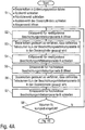
- a residual volume of air is introduced into the metering cylinder 8.
- step S3 the shut-off valve 7, the outlet valve 12, the flushing valve 15 and the return valve 18 are then closed.
- a counter i 0 is then initialized.
- step S5 the metering piston 9 is then moved by the metering drive 10 so that the volume of air in the metering cylinder 8 is compressed.
- a step S6 the metering drive 10 is then switched off. This has the consequence that the metering piston 9 is released, so that the compressed air can jump back the metering piston 9 jerky. This jerky springing back of the metering piston generates turbulences in the metering cylinder 8, which contributes to an improvement in the mixing of the coating agent components.
- step S8 it is then checked whether the desired number i MAX of mixing processes has been reached.
- the outlet valve 12 is opened in a step S9 and the coating agent mixture can be passed from the metering cylinder 8 to the application device 1.
- the jerky reciprocating movement of the metering piston 9 can not only be used to improve the mixing of the coating agent components in the metering cylinder 8. Rather, the jerky reciprocating movement of the metering piston 9 is also suitable for improving the detachment of coating agent residues from the inner walls of the metering cylinder 8 during a flushing process, as in FIG FIG. 6 is shown.
- the flowchart according to FIG. 6 is thus largely consistent with the flowchart FIG. 5 so as to avoid repetition essentially to the above description FIG. 5 can be referenced.
- the dosing cylinder 8 is filled with a mixture of rinsing agent, air and coating agent residues. Subsequently, the metering piston 9 is then jerked back and forth, as already above FIG. 5 has been described.
- FIG. 2 shows a modification of the embodiment according to FIG. 1 , so that in order to avoid repetition, reference is made to the above description, wherein the same reference numerals are used for corresponding details, which are, however, provided with the addition “.1” or “.2” for the purpose of distinction.
- a special feature of this embodiment is that in this case two dosing 8.1, 8.2 and two static mixers 13.1, 13.2 are connected in series. This serves to improve the mixing and allows complete electrical isolation.
- the material return 16.2 with the return valve 18.2 is not connected directly to the downstream metering cylinder 8.2, as is the case with the metering cylinder 8.1.
- the static mixer 13.2 is arranged between the material return 16.2 and the metering cylinder 8.2.
Landscapes
- Engineering & Computer Science (AREA)
- Chemical & Material Sciences (AREA)
- Chemical Kinetics & Catalysis (AREA)
- Mechanical Engineering (AREA)
- General Engineering & Computer Science (AREA)
- Dispersion Chemistry (AREA)
- Accessories For Mixers (AREA)
- Application Of Or Painting With Fluid Materials (AREA)
Abstract
Description
- Die Erfindung betrifft eine Mischanlage bzw. ein Mischverfahren zum Mischen von mehreren Komponenten (z.B. Beschichtungsmittelkomponenten) in einem vorgegebenen Mischungsverhältnis zu einem Gemisch (z.B. Beschichtungsmittelgemisch), beispielsweise zum Mischen von Kunststoffen oder zum Mischen eines Stammlacks mit einem Härter zu einem Zweikomponentenlack.
- Derartige Mischanlagen sind aus dem Stand der Technik in verschiedenen Ausgestaltungen bekannt, die nachfolgend kurz beschrieben werden.
- Beispielsweise sind Einspritzmischsysteme bekannt, bei denen ein kontinuierlicher Strom einer ersten Beschichtungsmittelkomponente laufend gemessen wird. Beim Erreichen einer bestimmten Mindestmenge der Beschichtungsmittelkomponente wird dann eine bestimmte Einspritzmenge einer zweiten Beschichtungsmittelkomponente in den Strom eingespritzt. Dieser Vorgang wiederholt sich dann laufend, so dass die beiden Beschichtungsmittelkomponenten mit dem gewünschten Mischungsverhältnis zusammengeführt werden. Allerdings erfordern derartige Einspritzmischsysteme in der Regel noch einen statischen Mischer, um das Beschichtungsmittelgemisch gleichmäßiger zu mischen.
- Weiterhin sind zum Mischen von verschiedenen Beschichtungsmittelkomponenten Dosierpumpensysteme bekannt, bei denen Dosierpumpen die verschiedenen Beschichtungsmittelkomponenten in einem gemeinsamen Kanal zusammenführen, wobei das Beschichtungsmittelgemisch dann in der Regel auch noch durch einen statischen Mischer geleitet wird, um die Beschichtungsmittelkomponenten gleichmäßiger zu mischen. Hierbei wird das Mischungsverhältnis durch die Fördermengen der Dosierpumpen eingestellt.
- Eine Abwandlung derartiger Dosierpumpensysteme sind Dosierkolbensysteme, bei denen anstelle von Dosierpumpen Dosierzylinder mit verschiebbaren Dosierkolben treten.
- Ferner sind Mischkammersysteme bekannt, bei denen die einzelnen Beschichtungsmittelkomponenten beispielsweise durch Dosierpumpen oder Dosierzylinder in eine Mischkammer eingebracht und dort beispielsweise durch ein Rührwerk vermischt werden. Ein solches Mischkammersystem ist beispielsweise aus
EP 0 334 092 A1 bekannt. - Weiterhin ist aus
DE 10 2015 008 659 A1 eine Mischeinrichtung bekannt, die in einen Zerstäuber integriert werden kann. Hierbei wählt eine Wechselventilanordnung die zu mischenden Beschichtungsmittelkomponenten aus und führt diese am Ausgang der Wechselventilanordnung zusammen, wobei das Beschichtungsmittelgemisch dann noch durch einen statischen Mischer (z.B. Gittermischer, Wendelmischer) geleitet wird. - Zum allgemeinen technischen Hintergrund der Erfindung ist auch hinzuweisen auf
DE 37 25 646 A1 . - Ferner offenbart
DE 20 2008 001 992 U1 eine Mischanlage zum Mischen von Komponenten eines Beschichtungsmittels. Die verschiedenen Komponenten werden hierbei über Einlassventile nacheinander in einen Dosierzylinder gegeben, wobei eine Waage die jeweilige Füllmenge misst und die Öffnungs- bzw. Schließzeiten der Einlassventile entsprechend steuert. Nachteilig an dieser bekannten Mischanlage ist die Tatsache, dass eine Waage zur Messung der jeweiligen Füllmengen erforderlich ist. - Die vorstehend beschriebenen bekannten Mischeinrichtungen sind jedoch noch nicht vollständig befriedigend.
- Der Erfindung liegt deshalb die Aufgabe zugrunde, eine verbesserte Mischanlage bzw. ein entsprechendes Mischverfahren zu schaffen.
- Diese Aufgabe wird durch eine Mischanlage bzw. ein Mischverfahren gemäß den unabhängigen Ansprüchen gelöst.
- Die erfindungsgemäße Mischanlage eignet sich zum Mischen von mehreren Beschichtungsmittelkomponenten in einem vorgegebenen Mischungsverhältnis zu einem Beschichtungsmittelgemisch. Beispielsweise kann die erfindungsgemäße Mischanlage eingesetzt werden, um einen Stammlack mit einem Härter zu einem Zweikomponentenlack zu mischen. Die Erfindung ist jedoch hinsichtlich des Typs der zu mischenden Beschichtungsmittelkomponenten nicht auf Stammlack und Härter beschränkt. Vielmehr eignet sich die Erfindung auch zur Mischung anderer Typen von Beschichtungsmittelkomponenten. Weiterhin ist zu erwähnen, dass die Erfindung hinsichtlich der Anzahl der zu mischenden Beschichtungsmittelkomponenten nicht auf genau zwei Beschichtungsmittelkomponenten beschränkt ist. Vielmehr eignet sich die Erfindung auch zum Mischen einer größeren Anzahl von Beschichtungsmittelkomponenten.
- Darüber hinaus eignet sich die Erfindung auch zum Mischen anderer Komponenten als Beschichtungsmittelkomponenten. Beispielsweise kann es sich bei den zu mischenden Komponenten um Kunststoffe handeln. So können beispielsweise milchige Plastisole in der Spielzeugindustrie eingefärbt werden, indem Grundfarbpigmente gemischt werden, um den gewünschten Farbton zu erreichen. Ein weiteres Beispiel sind Kleber, die eingefärbt werden, um bestimmte Farbkontraste in Fugen von Kanten zu vermeiden. Im Folgenden wird jedoch zur Vereinfachung der konkrete Begriff "Beschichtungsmittelkomponenten" verwendet, was jedoch keine Beschränkung bedeuten soll.
- Die erfindungsgemäße Mischanlage weist zunächst in Übereinstimmung mit dem Stand der Technik gemäß
DE 10 2015 008 659 A1 eine Wechselventilanordnung mit mehreren Einlässen zur Zuführung der zu mischenden Beschichtungsmittelkomponenten und einem gemeinsamen Auslass zur Abgabe der zu mischenden Beschichtungsmittelkomponenten auf. - Vorzugsweise dient die Wechselventilanordnung nicht nur zur Steuerung des Materialzuflusses für die einzelnen Beschichtungsmittelkomponenten, sondern auch zur Auswahl der zu mischenden Beschichtungsmittelkomponenten aus einer Vielzahl von zur Verfügung stehenden Beschichtungsmittelkomponenten. Beispielsweise ist es denkbar, dass die Wechselventilanordnung einen von zahlreichen Stammlacken auswählt und mit einem gemeinsamen oder einem individuell passenden Härter zusammenführt.
- Hierbei ist zu erwähnen, dass die Wechselventilanordnung die zu mischenden Beschichtungsmittelkomponenten am Auslass vorzugsweise sequentiell abgibt, d.h. ohne eine zeitliche Überlappung. Am Auslass der Wechselventilanordnung wird also vorzugsweise noch kein Beschichtungsmittelgemisch abgegeben. Vielmehr treten die zu mischenden Beschichtungsmittelkomponenten am Auslass der Wechselventilanordnung vorzugsweise sequentiell und ungemischt aus.
- Die erfindungsgemäße Mischanlage zeichnet sich nun durch einen Dosierzylinder aus, der mit dem Auslass der Wechselventilanordnung verbunden ist und die zu mischenden Beschichtungsmittelkomponenten von der Wechselventilanordnung aufnimmt. In dem Dosierzylinder befindet sich ein verschiebbarer Dosierkolben, der beim Befüllen des Dosierzylinders verschoben wird, so dass die Kolbenbewegung des Dosierkolbens die Füllmenge der jeweiligen Beschichtungsmittelkomponente definiert. Die zu mischenden Beschichtungsmittelkomponenten werden also von der Wechselventilanordnung ausgewählt, dem Dosierzylinder zugeführt und in dem Dosierzylinder zusammengeführt.
- Der im Rahmen der Erfindung verwendete Begriff eines Dosierzylinders ist allgemein zu verstehen und nicht beschränkt auf einen Dosierzylinder mit einem exakt kreisförmigen Innenquerschnitt. Vielmehr können der Dosierzylinder und der Dosierkolben auch beliebige andere Querschnitte aufweisen. Entscheidend ist lediglich, dass der Dosierkolben in dem Dosierzylinder verschiebbar ist, um die Füllmenge des jeweiligen Beschichtungsmittels zu definieren.
- In einem bevorzugten Ausführungsbeispiel der Erfindung ist ein Dosierantrieb vorgesehen, um den Dosierkolben in dem Dosierzylinder entsprechend der definierten Füllmenge des jeweiligen Beschichtungsmittels zu bewegen. In diesem Zusammenhang ist zu erwähnen, dass der im Rahmen der Erfindung verwendete Begriff eines Dosierzylinders vorzugsweise impliziert, dass die jeweilige Füllmenge der jeweiligen Beschichtungsmittelkomponente genau eingestellt werden kann, was dem Begriff des Dosierens entspricht.
- Vorzugsweise weist der Dosierantrieb einen Elektromotor (z.B. Servomotor) auf, der über ein Schraubgetriebe (z.B. Kugelgewindegetriebe) oder über einen Zahnriemen auf den Dosierkolben wirken kann.
- Weiterhin ist es vorteilhaft, wenn der Dosierantrieb einen Drehwinkelgeber aufweist, der den Drehwinkel des Elektromotors misst, wobei der Drehwinkel des Elektromotors auch die Füllmenge definiert. Der Drehwinkelgeber ermöglicht also mittelbar eine genaue Messung der Füllmenge der jeweiligen Beschichtungsmittelkomponente. Der Drehwinkelgeber verfügt deshalb vorzugsweise über eine sehr große Winkelauflösung, um eine hohe Dosiergenauigkeit zu erreichen. Die Winkelauflösung des Drehwinkelgebers kann deshalb im Rahmen der Erfindung mindestens 2000, 4000, 8000, 16000, 32000, 64000 oder sogar mindestens 128000 Inkremente pro Umdrehung betragen, um eine entsprechend hohe Dosiergenauigkeit zu erzielen.
- Darüber hinaus besteht im Rahmen der Erfindung die Möglichkeit, dass kinematisch zwischen dem Elektromotor und dem Dosierkolben eine Welle und/oder eine Kolbenstange aus einem elektrisch isolierenden Material angeordnet ist, um eine Potentialtrennung zu ermöglichen. Dies ist insbesondere dann vorteilhaft, wenn das Beschichtungsmittelgemisch für eine elektrostatische Beschichtungsmittelaufladung elektrisch aufgeladen werden soll.
- Der Dosierantrieb ermöglicht vorzugsweise - wie bereits vorstehend kurz erwähnt wurde - eine hohe Dosiergenauigkeit mit sehr geringen Dosierfehlern. Die Dosierfehler können beispielsweise kleiner sein als ±10ml, ±5ml, ±2ml, ±1ml, ±500n1, ±200nl oder sogar ±100nl.
- Alternativ zu dem vorstehend erwähnten Elektroantrieb des Dosierantriebs besteht auch die Möglichkeit, dass der Dosierantrieb pneumatisch oder hydraulisch arbeitet.
- Es wurde bereits vorstehend kurz erwähnt, dass der Dosierzylinder mit dem Auslass der Wechselventilanordnung verbunden ist, d.h. der Dosierzylinder wird aus dem Ausgang der Wechselventilanordnung befüllt. Vorzugsweise ist zwischen dem Auslass der Wechselventilanordnung und dem Dosierzylinder ein steuerbares Absperrventil angeordnet, um die Materialabgabe aus der Wechselventilanordnung in den Dosierzylinder zu steuern.
- Der Dosierzylinder gibt das vorgemischte Beschichtungsmittelgemisch dann an ein Applikationsgerät ab, wobei zwischen dem Dosierzylinder und dem Applikationsgerät ein steuerbares Auslassventil und/oder ein statischer Mischer (z.B. Gittermischer, Wendelmischer) angeordnet sein können, wobei der statische Mischer die Aufgabe hat, die von dem Dosierzylinder nur vorgemischten Beschichtungsmittelkomponenten gleichmäßiger zu mischen.
- Ferner kann die erfindungsgemäße Mischanlage eine Materialrückführung aufweisen, um bei einem Spülvorgang Beschichtungsmittelreste aus dem Dosierzylinder aufzunehmen. Beispielsweise kann diese Materialrückführung einen Sammelbehälter für die Beschichtungsmittelreste aufweisen.
- Hierbei ist vorzugsweise ein steuerbares Spülmittelventil vorgesehen, um die Zuführung von Spülmittel in den Dosierzylinder zu steuern.
- Darüber hinaus kann auch ein steuerbares Rückführventil vorgesehen sein, um die Materialabgabe aus dem Dosierzylinder in die Materialrückführung zu steuern.
- Im Rahmen der Erfindung besteht auch die Möglichkeit, dass stromabwärts hinter der Wechselventilanordnung mehrere Dosierzylinder und/oder mehrere statische Mischer in Strömungsrichtung hintereinander angeordnet sind, was auch eine Potentialtrennung ermöglicht. Den einzelnen Dosierzylindern ist vorzugsweise jeweils ein Spülmittelventil, ein Rückführventil, ein Absperrventil und/oder ein Auslassventil zugeordnet.
- Der Anschluss der Materialrückführung kann jedoch bei den verschiedenen Dosierzylindern unterschiedlich erfolgen. So kann die Materialrückführung mit dem zugehörigen Rückführventil bei dem stromaufwärtigen Dosierzylinder unmittelbar an den Dosierzylinder angeschlossen sein. Bei dem stromabwärtigen Dosierzylinder kann dagegen zwischen Dosierzylinder und Materialrückführung der statische Mischer angeordnet sein.
- Weiterhin ist noch zu erwähnen, dass sich die erfindungsgemäße Mischanlage für eine sehr große Viskositätsbandbreite eignet, d.h. es können Beschichtungsmittelkomponenten mit sehr unterschiedlichen Viskositäten gemischt werden. Beispielsweise kann die Viskositätsbandbreite 15MPa·s bis 10000MPa·s betragen.
- Zusätzlich zu der vorstehend beschriebenen Mischanlage beansprucht die Erfindung auch Schutz für ein entsprechendes Mischverfahren, wobei sich die einzelnen Verfahrensschritte des erfindungsgemäßen Mischverfahrens bereits aus der Beschreibung ergeben und deshalb nicht separat beschrieben werden müssen.
- Es ist jedoch zu erwähnen, dass zur Durchmischung der Beschichtungsmittelkomponenten in dem Dosierzylinder oder zum Lösen von Beschichtungsmittelrückständen in dem Dosierzylinder die Möglichkeit besteht, den Dosierkolben ruckartig hin- und herzubewegen. Bei dieser ruckartigen Hin- und Herbewegung des Dosierkolbens entstehen Turbulenzen in dem Dosierzylinder, die zur Durchmischung der Beschichtungsmittelkomponenten bzw. zum Lösen von Beschichtungsmittelrückständen bei einem Spülvorgang beitragen.
- Das Hin- und Herbewegen des Dosierkolbens kann beispielsweise dadurch erreicht werden, dass zusätzlich zu den zu mischenden Beschichtungsmittelkomponenten bzw. dem Spülmittel ein Restvolumen von Luft in den Dosierzylinder eingefüllt wird. Der Dosierantrieb wird dann eingeschaltet, um die Luft in dem Dosierzylinder zu komprimieren. Beim Ausschalten des Dosierantriebs wird der Dosierkolben dann freigegeben, so dass die komprimierte Luft den Dosierkolben ruckartig zurückspringen lässt, wodurch in dem Dosierzylinder Turbulenzen entstehen, die zur Verbesserung der Durchmessung bzw. zum Lösen der Beschichtungsmittelrückstände in dem Dosierzylinder beitragen. Die Luft kann dann beispielsweise aus dem Dosierzylinder abgelassen werden.
- Ferner ist zu erwähnen, dass die verschiedenen zu mischenden Beschichtungsmittelkomponenten vorzugsweise in einer bestimmten Reihenfolge in den Dosierzylinder eingefüllt werden.
- Beispielsweise kann die Reihenfolge der Befüllung des Dosierzylinders an der Viskosität der zu befüllenden Beschichtungsmittelkomponenten orientiert werden. Vorzugsweise wird hierbei mit der Befüllung von niederviskosen Beschichtungsmittelkomponenten begonnen, um dann mit der Befüllung von höher viskosen Beschichtungsmittelkomponenten fortzuschreiten.
- Alternativ besteht auch die Möglichkeit, dass die Reihenfolge der Befüllung der verschiedenen Beschichtungsmittelkomponenten an der jeweiligen Füllmenge orientiert wird, wobei vorzugsweise mit einer Befüllung kleiner Füllmengen begonnen und mit einer Befüllung großer Füllmengen fortgesetzt wird.
- Schließlich besteht auch die Möglichkeit, dass zunächst Stammlack eingefüllt wird, während der Härter zuletzt eingefüllt wird.
- Andere vorteilhafte Weiterbildungen der Erfindung sind in den Unteransprüchen gekennzeichnet oder werden nachstehend zusammen mit der Beschreibung der bevorzugten Ausführungsbeispiele der Erfindung anhand der Figuren näher erläutert. Es zeigen:
- Figur 1
- eine schematische Darstellung einer erfindungsgemäßen Mischanlage,
- Figur 2
- eine Abwandlung von
Figur 1 mit zwei Dosierzylindern und zwei statischen Mischern, - Figur 3
- eine schematische Darstellung des erfindungsgemäßen Mischverfahrens in Form eines Flussdiagramms,
- Figuren 4A und 4B
- eine Abwandlung des Flussdiagramms gemäß
Figur 3 , - Figur 5
- ein Flussdiagramm zur Verdeutlichung der Verbesserung der Durchmischung durch ein ruckartiges Hin- und Herbewegen des Dosierkolbens, und
- Figur 6
- ein Flussdiagramm zur Verdeutlichung der Verbesserung der Spülwirkung durch ruckartiges Hin- und Herbewegen des Dosierkolbens.
-
Figur 1 zeigt ein Ausführungsbeispiel einer erfindungsgemäßen Mischanlage zum Mischen mehrerer Beschichtungsmittelkomponenten (z.B. Härter und verschiedene Stammlacke) zu einem Beschichtungsmittelgemisch, das dann von einem Applikationsgerät 1 (z.B. Zerstäuber) auf ein Bauteil (z.B. Kraftfahrzeugkarosseriebauteil) appliziert werden kann. - Hierzu weist die erfindungsgemäße Mischanlage zunächst eine Wechselventilanordnung 2 mit zahlreichenden Einlässen 3 auf, um die zu mischenden Beschichtungsmittelkomponenten zuzuführen. Beispielsweise können über die Einlässe 3 der Wechselventilanordnung 2 mehrere verschiedene Stammlacke und ein Härter zugeführt werden.
- Den einzelnen Einlässen 3 der Wechselventilanordnung 2 ist jeweils ein Einlassventil 4 zugeordnet, um den Materialfluss aus den einzelnen Einlässen 3 in einen gemeinsamen Kanal 5 hin zu einem Auslass 6 der Wechselventilanordnung 2 zu steuern.
- Der Auslass 6 der Wechselventilanordnung 2 ist über ein Absperrventil 7 mit einem Dosierzylinder 8 verbunden.
- In dem Dosierzylinder 8 ist ein Dosierkolben 9 von einem Dosierantrieb 10 mit einem Servomotor verschiebbar, wobei der Dosierantrieb 10 über eine elektrisch isolierende Kolbenstange 11 auf den Dosierkolben 9 wirkt. Die elektrisch isolierende Kolbenstange 11 ermöglicht hierbei eine Potentialtrennung im Rahmen einer elektrostatischen Beschichtungsmittelaufladung.
- Der Dosierzylinder 8 ist über ein Auslassventil 12, einen statischen Mischer 13 (z.B. Gittermischer, Wendelmischer) und ein Hauptventil 14 mit dem Applikationsgerät 1 verbunden.
- Darüber hinaus weist die Mischanlage noch ein Spülmittelventil 15 auf, um bei einem Spülvorgang Spülmittel in den Dosierzylinder 8 einzuleiten.
- Ferner umfasst die Mischanlage eine Materialrückführung 16, die in einen Sammelbehälter 17 mündet.
- Zwischen dem Sammelbehälter 17 und dem Dosierzylinder 8 ist hierbei noch ein steuerbares Rückführventil 18 angeordnet, um die Materialabgabe aus dem Dosierzylinder 8 in den Sammelbehälter 17 zu steuern.
- Im Folgenden wird nun die Betriebsweise der Mischanlage beschrieben, wobei auf das Flussdiagramm gemäß
Figur 3 Bezug genommen wird. - In einem ersten Schritt S1 wird der Dosierkolben 9 in eine Entleerungsposition gefahren, d.h. in der Zeichnung in die obere Stellung. Weiterhin werden das Spülmittelventil 15, das Rückführventil 18 und das Auslassventil 12 geschlossen, während das Absperrventil 7 zwischen der Wechselventilanordnung 2 und dem Dosierzylinder 8 geöffnet wird.
- In einem Schritt S2 wird dann das gewünschte Einlassventil 4 geöffnet, wobei zunächst eine niedrigviskose Beschichtungsmittelkomponente A ausgewählt wird.
- In einem nächsten Schritt S3 wird der Dosierkolben 9 dann von dem Dosierantrieb 10 gesteuert so verfahren, dass ein definiertes Volumen VA der ausgewählten Beschichtungsmittelkomponente A in den Dosierzylinder 8 gefüllt wird.
- In einem weiteren Schritt S4 wird dann das Einlassventil für die niedrigviskose Beschichtungsmittelkomponente A geschlossen und ein anderes Einlassventil für eine hochviskose Beschichtungsmittelkomponente B wird in einem Schritt S5 geöffnet.
- In einem Schritt S6 wird der Dosierkolben 9 dann gesteuert so verfahren, dass wieder ein definiertes Volumen VB der Beschichtungsmittelkomponente B in den Dosierzylinder 8 gesaugt wird.
- In einem Schritt S7 wird dann das Einlassventil für die hochviskose Beschichtungsmittelkomponente B geschlossen.
- In einem Schritt S8 wird dann das Absperrventil 7 geschlossen, wohingegen das Auslassventil 12 geöffnet wird.
- Der Dosierkolben 9 wird dann in einem Schritt S9 gesteuert verfahren und drückt dabei das in dem Dosierzylinder 8 befindliche, vorgemischte Beschichtungsmittelgemisch A+B aus dem Dosierzylinder 8 durch den statischen Mischer 13 hin zu dem Applikationsgerät 1.
- In einem nächsten Schritt S10 wird dann das Auslassventil 12 geschlossen, während das Spülmittelventil 15 und das Rückführventil 18 geöffnet werden.
- In einem Schritt S11 wird dann der Dosierzylinder 8 gespült. Dabei wird über das Spülmittelventil 15 Spülmittel in den Dosierzylinder eingeleitet, wodurch Beschichtungsmittelrückstände entfernt und über das geöffnete Rückführventil 18 in den Sammelbehälter 17 geleitet werden.
- In einem Schritt S12 werden dann das Spülmittelventil 15 und das Rückführventil 18 geschlossen.
- Die
Figuren 4A und4B zeigen eine Abwandlung des Mischverfahrens gemäßFigur 3 , so dass zur Vermeidung von Wiederholungen auf die vorstehende Beschreibung verwiesen wird. - Eine Besonderheit dieses Ausführungsbeispiels besteht darin, dass jeweils nicht die vollständigen Füllmengen VA bzw. VB in den Dosierzylinder 8 eingefüllt werden. Vielmehr werden in den Schritten S3 bzw. S6 jeweils nur Teilvolumina VA/x bzw. VB/x der gewünschten Befüllmengen in den Dosierzylinder 8 eingefüllt. Die Befüllung mit den Teilvolumina VA/x bzw. VB/x wird so oft zyklisch wiederholt, bis die gewünschten Gesamtmengen VA bzw. VB in den Dosierzylinder eingefüllt sind. Durch diese Vorgehensweise wird der Mischungsgrad beim Befüllen des Dosierzylinders 8 verbessert.
-
Figur 5 zeigt in Form eines Flussdiagramms eine erfindungsgemäße Variante zur Verbesserung der Durchmischung der verschiedenen Beschichtungsmittelkomponenten in dem Dosierzylinder. Hierbei wird der Dosierzylinder 8 zunächst in einem Schritt S1 mit den gewünschten Beschichtungsmittelkomponenten befüllt. - Anschließend wird dann in einem Schritt S2 ein Restvolumen Luft in den Dosierzylinder 8 eingefüllt.
- In einem Schritt S3 werden dann das Absperrventil 7, das Auslassventil 12, das Spülmittelventil 15 und das Rückführventil 18 geschlossen.
- In einem Schritt S4 wird dann ein Zähler i=0 initialisiert.
- Im nächsten Schritt S5 wird dann der Dosierkolben 9 von dem Dosierantrieb 10 so bewegt, dass das Luftvolumen in dem Dosierzylinder 8 komprimiert wird.
- In einem Schritt S6 wird der Dosierantrieb 10 dann ausgeschaltet. Dies hat zur Folge, dass der Dosierkolben 9 freigegeben wird, so dass die komprimierte Luft den Dosierkolben 9 ruckartig zurückspringen lässt. Dieses ruckartige Zurückspringen des Dosierkolbens erzeugt in dem Dosierzylinder 8 Turbulenzen, was zu einer Verbesserung der Durchmischung der Beschichtungsmittelkomponenten beiträgt.
- In einem Schritt S7 wird dann der Zähler i=i+1 inkrementiert.
- In einem Schritt S8 wird dann geprüft, ob die gewünschte Anzahl iMAX an Durchmischungsvorgängen erreicht ist.
- Falls dies der Fall ist, so wird in einem Schritt S9 das Auslassventil 12 geöffnet und das Beschichtungsmittelgemisch kann aus dem Dosierzylinder 8 zu dem Applikationsgerät 1 geleitet werden.
- Das ruckartige Hin- und Herbewegen des Dosierkolbens 9 kann nicht nur dazu verwendet werden, die Durchmischung der Beschichtungsmittelkomponenten in dem Dosierzylinder 8 zu verbessern. Vielmehr eignet sich das ruckartige Hin- und Herbewegen des Dosierkolbens 9 auch dazu, bei einem Spülvorgang das Ablösen von Beschichtungsmittelrückständen von den Innenwänden des Dosierzylinders 8 zu verbessern, wie in
Figur 6 dargestellt ist. Das Flussdiagramm gemäßFigur 6 stimmt somit weitgehend mit dem Flussdiagramm gemäßFigur 5 überein, so dass zur Vermeidung von Wiederholungen im Wesentlichen auf die vorstehende Beschreibung zuFigur 5 verwiesen werden kann. - Es ist lediglich zu erwähnen, dass der Dosierzylinder 8 hierbei mit einem Gemisch aus Spülmittel, Luft und Beschichtungsmittelrückständen befüllt wird. Anschließend wird dann der Dosierkolben 9 ruckartig hin- und herbewegt, wie bereits vorstehend zu
Figur 5 beschrieben wurde. -
Figur 2 zeigt eine Abwandlung des Ausführungsbeispiels gemäßFigur 1 , so dass zur Vermeidung von Wiederholungen auf die vorstehende Beschreibung verwiesen wird, wobei für entsprechende Einzelheiten dieselben Bezugszeichen verwendet werden, die jedoch zur Unterscheidung mit dem Zusatz ".1" bzw. ".2" versehen sind. - Eine Besonderheit dieses Ausführungsbeispiels besteht darin, dass hierbei zwei Dosierzylinder 8.1, 8.2 und zwei statische Mischer 13.1, 13.2 hintereinander geschaltet sind. Dies dient zur Verbesserung der Durchmischung und ermöglicht eine vollständige elektrische Potentialtrennung.
- Hierbei ist noch zu erwähnen, dass die Materialrückführung 16.2 mit dem Rückführventil 18.2 hierbei nicht direkt an den stromabwärtigen Dosierzylinder 8.2 angeschlossen ist, wie es bei dem Dosierzylinder 8.1 der Fall ist. Vielmehr ist hierbei zwischen der Materialrückführung 16.2 und dem Dosierzylinder 8.2 der statische Mischer 13.2 angeordnet.
- Die Erfindung ist nicht auf die vorstehend beschriebenen bevorzugten Ausführungsbeispiele beschränkt. Vielmehr ist eine Vielzahl von Varianten und Abwandlungen möglich, die ebenfalls von dem Erfindungsgedanken Gebrauch machen und deshalb in den Schutzbereich fallen. Insbesondere beansprucht die Erfindung auch Schutz für den Gegenstand und für die Merkmale der Unteransprüche unabhängig von den jeweils in Bezug genommenen Ansprüchen und insbesondere auch ohne die Merkmale des Hauptanspruchs. Die Unteransprüche und die Beschreibung umfassen also verschiedene Erfindungsaspekte, die unabhängig voneinander Schutz genießen.
-
- 1
- Applikationsgerät
- 2
- Wechselventilanordnung
- 3
- Einlässe der Wechselventilanordnung
- 4
- Einlassventile der Wechselventilanordnung
- 5
- Gemeinsamer Kanal der Wechselventilanordnung
- 6
- Auslass der Wechselventilanordnung
- 7, 7.1, 7.2
- Absperrventil
- 8, 8.1, 8.2
- Dosierzylinder
- 9, 9.1, 9.2
- Dosierkolben
- 10, 10.1, 10.2
- Dosierantrieb
- 11, 11.1, 11.2
- Kolbenstange
- 12, 12.1, 12.2
- Auslassventil
- 13, 13.1, 13.2
- statischer Mischer
- 14
- Hauptventil
- 15, 15.1, 15.2
- Spülmittelventil
- 16, 16.1, 16.2
- Materialrückführung
- 17, 17.1, 17.2
- Sammelbehälter der Materialrückführung
- 18, 18.1, 18.2
- Rückführventil
Claims (15)
- Mischanlage zum Mischen von mehreren Komponenten, insbesondere Beschichtungsmittelkomponenten, in einem vorgegebenen Mischungsverhältnis zu einem Gemisch, insbesondere zu einem Beschichtungsmittelgemisch, insbesondere zum Mischen eines Stammlacks mit einem Härter zu einem Zweikomponentenlack, mita) einer Wechselventilanordnung (2) mit mehreren Einlässen (3) mit jeweils einem individuell steuerbaren Einlassventil (4) zur Zuführung der zu mischenden Komponenten und einem gemeinsamen Auslass (6) zur Abgabe der zu mischenden Komponenten, insbesondere zur sequentiellen Abgabe der zu mischenden Komponenten,gekennzeichnet durchb) einen Dosierzylinder (8; 8.1, 8.2) am Auslass (6) der Wechselventilanordnung (2), wobei der Dosierzylinder (8; 8.1, 8.2) einen verschiebbaren Dosierkolben (9; 9.1, 9.2) aufweist und die zu mischenden Komponenten entsprechend der Kolbenbewegung des Dosierkolbens (9; 9.1, 9.2) jeweils mit einer definierten Füllmenge aus dem Auslass (6) der Wechselventilanordnung (2) aufnimmt und in dem Dosierzylinder (8; 8.1, 8.2) zusammenführt, um das vorgegebene Mischungsverhältnis einzustellen.
- Mischanlage nach Anspruch 1, dadurch gekennzeichnet,a) dass ein Dosierantrieb (10; 10.1, 10.2) vorgesehen ist zum Verschieben des Dosierkolbens (9; 9.1, 9.2) in dem Dosierzylinder (8; 8.1, 8.2) entsprechend der definierten Füllmenge des jeweiligen Beschichtungsmittels, und/oderb) dass der Dosierantrieb (10; 10.1, 10.2) einen Elektromotor aufweist, insbesondere einen Servomotor, und/oderc) dass der Elektromotor über ein Schraubgetriebe, insbesondere über ein Kugelgewindegetriebe, oder über einen Zahnriemen auf den Dosierkolben (9; 9.1, 9.2) wirkt, und/oderd) dass der Dosierantrieb (10; 10.1, 10.2) einen Drehwinkelgeber aufweist, der einen Drehwinkel des Elektromotors misst, insbesondere mit einer Winkelauflösung von mindestens 2000, 4000, 8000, 16000, 32000, 64000 oder 128000 Inkrementen pro Umdrehung, um eine hohe Dosiergenauigkeit zu erreichen, und/odere) dass kinematisch zwischen dem Elektromotor und dem Dosierkolben (9; 9.1, 9.2) eine Welle und/oder eine Kolbenstange (11; 11.1, 11.2) aus einem elektrisch isolierenden Material angeordnet ist, um eine Potentialtrennung zu ermöglichen, und/oderf) dass der Dosierantrieb (10; 10.1, 10.2) eine hohe Dosiergenauigkeit ermöglicht mit Dosierfehlern von weniger als ±10ml, ±5ml, ±2ml, ±1ml, ±500nl, ±200nl oder ±100nl, und/oderg) dass der Dosierantrieb (10; 10.1, 10.2) pneumatisch oder hydraulisch arbeitet.
- Mischanlage nach einem der vorhergehenden Ansprüche, gekennzeichnet durcha) ein steuerbares Absperrventil (7; 7.1, 7.2) zwischen dem Auslass (6) der Wechselventilanordnung (2) und dem Dosierzylinder (8; 8.1, 8.2) zur Steuerung der Materialabgabe von der Wechselventilanordnung (2) in den Dosierzylinder (8; 8.1, 8.2), und/oderb) ein steuerbares Auslassventil (12; 12.1, 12.2) zur Steuerung der Materialabgabe aus dem Dosierzylinder (8; 8.1, 8.2) zu einem Applikationsgerät (1).
- Mischanlage nach einem der vorhergehenden Ansprüche, gekennzeichnet durcha) eine Materialrückführung (16; 16.1, 16.2), insbesondere mit einem Sammelbehälter (17; 17.1, 17.2), zur Aufnahme von Beschichtungsmittelresten aus dem Dosierzylinder (8; 8.1, 8.2) bei einem Spülvorgang,b) ein steuerbares Spülmittelventil (15; 15.1, 15.2) zur Zuführung von Spülmittel in den Dosierzylinder (8; 8.1, 8.2), und/oderc) ein steuerbares Rückführventil (18; 18.1, 18.2) zur Steuerung der Materialabgabe aus dem Dosierzylinder (8; 8.1, 8.2) in die Materialrückführung (16; 16.1, 16.2).
- Mischanlage nach einem der vorhergehenden Ansprüche, gekennzeichnet durch einen statischen Mischer (13; 13.1, 13.2), der eingangsseitig mit dem Dosierzylinder (8; 8.1, 8.2) verbunden und von dem vorgemischten Beschichtungsmittelgemisch durchströmt wird, um das Beschichtungsmittelgemisch gleichmäßiger zu mischen.
- Mischanlage nach einem der vorhergehenden Ansprüche, dadurch gekennzeichnet,a) dass stromabwärts hinter der Wechselventilanordnung (2) mehrere Dosierzylinder (8.1, 8.2) und/oder mehrere statische Mischer (13.1, 13.2) in Strömungsrichtung hintereinander angeordnet sind, und/oderb) dass die Dosierzylinder (8.1, 8.2) eine Potentialtrennung ermöglichen.
- Mischanlage nach Anspruch 6, dadurch gekennzeichnet,a) dass die einzelnen Dosierzylinder (8.1, 8.2) durch jeweils ein steuerbares Spülmittelventil (15.1, 15.2) unabhängig voneinander spülbar sind, und/oderb) dass die einzelnen Dosierzylinder (8.1, 8.2) durch jeweils ein steuerbares Rückführventil (18.1, 18.2) in eine gemeinsame Materialrückführung oder in jeweils eine eigene Materialrückführung (16.1, 16.2) ausgespült werden können, und/oderc) dass die einzelnen Dosierzylinder (8.1, 8.2) eingangsseitig jeweils ein steuerbares Absperrventil (7.1, 7.2) aufweisen, und/oderd) dass die einzelnen Dosierzylinder (8.1, 8.2) auslassseitig jeweils ein steuerbares Auslassventil (12; 12.1, 12.2) aufweisen, und/odere) dass bei dem stromaufwärtigen Dosierzylinder (8.1) die Materialrückführung (16.1) direkt an den Dosierzylinder (8.2) angeschlossen ist, während bei dem stromabwärtigen Dosierzylinder (8.2) der stromabwärtige statische Mischer (13.2) zwischen der der stromabwärtigen Materialrückführung (16.2) und dem stromabwärtigen Dosierzylinder (8.2) angeschlossen ist.
- Mischverfahren zum Mischen von mehreren Komponenten, insbesondere Beschichtungsmittelkomponenten, in einem vorgegebenen Mischungsverhältnis zu einem Gemisch, insbesondere zu einem Beschichtungsmittelgemisch, insbesondere zum Mischen eines Stammlacks mit einem Härter zu einem Zweikomponentenlack, insbesondere mittels einer Mischanlage nach einem der vorhergehenden Ansprüche, mit folgenden Schritten:a) Auswählen der zu mischenden Komponenten mittels einer Wechselventilanordnung (2) mit mehreren Einlässen (3), an denen jeweils die einzelnen Komponenten anliegen, wobei die jeweils ausgewählten Komponenten einem gemeinsamen Auslass (6) der Wechselventilanordnung (2) zugeführt werden, insbesondere sequentiell,gekennzeichnet durch folgenden Schritt:b) Befüllen eines Dosierzylinders (8; 8.1, 8.2) mit einem verschiebbaren Dosierkolben (9; 9.1, 9.2) entsprechend der Kolbenbewegung des Dosierkolbens (9; 9.1, 9.2) jeweils mit einer bestimmten Füllmenge der verschiedenen Komponenten aus dem Auslass (6) der Wechselventilanordnung (2), so dass die zu mischenden Komponenten in dem Dosierzylinder (8; 8.1, 8.2) zusammengeführt werden.
- Mischverfahren nach Anspruch 8, dadurch gekennzeichnet,a) dass die verschiedenen Komponenten von der Wechselventilanordnung (2) sequentiell ausgewählt und dem Auslass (6) der Wechselventilanordnung (2) sequentiell zugeführt werden, und/oderb) dass der Dosierzylinder (8; 8.1, 8.2) sequentiell mit den verschiedenen Komponenten befüllt wird, so dass die verschiedenen Komponenten in dem Dosierzylinder (8; 8.1, 8.2) zusammengeführt und vorgemischt werden, und/oderc) dass der Dosierzylinder (8; 8.1, 8.2) sequentiell und wiederholt mit Teilmengen der verschiedenen Komponenten befüllt wird bis für jede der zu mischenden Komponenten die gewünschte Gesamtmenge in den Dosierzylinder (8; 8.1, 8.2) eingefüllt ist.
- Mischverfahren nach Anspruch 9, dadurch gekennzeichnet, dass der Dosierkolben (9; 9.1, 9.2) beim Befüllen des Dosierzylinders (8; 8.1, 8.2) mit den verschiedenen Komponenten von einem Dosierantrieb (10; 10.1, 10.2) gesteuert bewegt wird, um eine definierte Füllmenge der jeweiligen Komponente in den Dosierzylinder (8; 8.1, 8.2) aufzunehmen.
- Mischverfahren nach Anspruch 9 oder 10, gekennzeichnet durch folgenden Schritt:
Entleeren des Dosierzylinders (8; 8.1, 8.2) mit dem darin befindlichen Gemisch in einen statischen Mischer hin zu einem Applikationsgerät (1), so dass das Gemisch in dem statischen Mischer gleichmäßiger gemischt wird. - Mischverfahren nach einem der Ansprüche 9 bis 11, gekennzeichnet durch folgenden Schritt zum Vormischen der verschiedenen Komponenten in dem Dosierzylinder (8; 8.1, 8.2) oder zum Lösen von Rückständen in dem Dosierzylinder (8; 8.1, 8.2) bei einem Spülvorgang:
Mehrfaches Hin- und Herbewegen des Dosierkolbens (9; 9.1, 9.2), insbesondere ruckartig, zur Erzeugung von Turbulenzen in dem Dosierzylinder (8; 8.1, 8.2). - Mischverfahren nach Anspruch 12, gekennzeichnet durch folgende Schritte zum Hin- und Herbewegen des Dosierkolbens (9; 9.1, 9.2) in dem Dosierzylinder (8; 8.1, 8.2):a) Befüllen eines Restvolumens des Dosierzylinders (8; 8.1, 8.2) zusätzlich zu den zu mischenden Komponenten oder dem Spülmittel mit Luft,b) Einschalten eines Dosierantriebs (10; 10.1, 10.2), so dass der Dosierkolben (9; 9.1, 9.2) bewegt wird und die Luft in dem Dosierzylinder (8; 8.1, 8.2) komprimiert, undc) Ausschalten des Dosierantriebs (10; 10.1, 10.2), so dass die komprimierte Luft in dem Dosierzylinder (8; 8.1, 8.2) den Dosierkolben (9; 9.1, 9.2) zurückspringen lässt, wodurch in dem Dosierzylinder (8; 8.1, 8.2) Turbulenzen entstehen und die Komponenten in dem Dosierzylinder (8; 8.1, 8.2) vorgemischt oder die Rückstände in dem Dosierzylinder (8; 8.1, 8.2) gelöst werden, undd) Vorzugsweise Ablassen der Luft aus dem Dosierzylinder (8; 8.1, 8.2) über ein Ablassventil.
- Mischverfahren nach einem der Ansprüche 9 bis 13, gekennzeichnet durch folgende Schritte zum Spülen des Dosierzylinders (8; 8.1, 8.2):a) Einspülen eines Spülmittels in den Dosierzylinder (8; 8.1, 8.2), insbesondere über ein steuerbares Spülmittelventil (15; 15.1, 15.2), zur Lösen von Rückständen des Gemischs in dem Dosierzylinder (8; 8.1, 8.2), und/oderb) Ausspülen der Rückstände des Gemischs aus dem Dosierzylinder (8; 8.1, 8.2) in eine Materialrückführung (16; 16.1, 16.2), insbesondere mit einem Sammelbehälter, insbesondere über ein steuerbares Rückführventil.
- Mischverfahren nach einem der Ansprüche 9 bis 14, dadurch gekennzeichnet, dass die zu mischenden Komponenten in einer vorgegebenen Reihenfolge in den Dosierzylinder (8; 8.1, 8.2) gefüllt werden, nämlicha) entsprechend der Viskosität der Komponenten beginnend mit einer niederviskosen Komponente gefolgt von einer höherviskosen Komponente, oderb) entsprechend der Füllmenge der einzelnen Komponenten beginnend mit einer Komponenten mit kleiner Füllmenge gefolgt von einer Komponente mit großer Füllmenge, oderc) beginnend mit dem Stammlack gefolgt von dem Härter.
Applications Claiming Priority (1)
| Application Number | Priority Date | Filing Date | Title |
|---|---|---|---|
| DE102017117584.9A DE102017117584B4 (de) | 2017-08-03 | 2017-08-03 | Mischanlage und entsprechendes Mischverfahren |
Publications (2)
| Publication Number | Publication Date |
|---|---|
| EP3444025A1 true EP3444025A1 (de) | 2019-02-20 |
| EP3444025B1 EP3444025B1 (de) | 2021-06-02 |
Family
ID=63041823
Family Applications (1)
| Application Number | Title | Priority Date | Filing Date |
|---|---|---|---|
| EP18185088.4A Active EP3444025B1 (de) | 2017-08-03 | 2018-07-24 | Mischanlage und entsprechendes mischverfahren |
Country Status (2)
| Country | Link |
|---|---|
| EP (1) | EP3444025B1 (de) |
| DE (1) | DE102017117584B4 (de) |
Cited By (2)
| Publication number | Priority date | Publication date | Assignee | Title |
|---|---|---|---|---|
| WO2021094278A1 (de) * | 2019-11-13 | 2021-05-20 | Dürr Systems Ag | Zerstäuber und zugehöriges betriebsverfahren |
| EP4426500A1 (de) * | 2021-11-02 | 2024-09-11 | Abb Schweiz Ag | Versorgungsvorrichtung zur versorgung eines beschichtungsmediums, beschichtungsmediumvorrichtung, system und verfahren zur versorgung eines beschichtungsmediums |
Families Citing this family (3)
| Publication number | Priority date | Publication date | Assignee | Title |
|---|---|---|---|---|
| CN113813872A (zh) * | 2021-08-27 | 2021-12-21 | 佛山市特赛化工设备有限公司 | 一种比例可调供料装置及混合机 |
| FR3151512A1 (fr) * | 2023-07-24 | 2025-01-31 | Exel Industries | Procédé de rinçage d’un dispositif d’application de produit de revêtement, et dispositif associé |
| FR3151672A1 (fr) * | 2023-07-24 | 2025-01-31 | Exel Industries | Procédé de dosage à alimentation alternative, et dispositifs associés |
Citations (3)
| Publication number | Priority date | Publication date | Assignee | Title |
|---|---|---|---|---|
| DE2821005A1 (de) * | 1977-05-13 | 1978-11-23 | Varian Associates | Verfahren zur gradientenproportionierung in einem fluessigkeitschromatographiesystem |
| US4595495A (en) * | 1985-02-22 | 1986-06-17 | Eldex Laboratories, Inc. | Programmable solvent delivery system and process |
| US20030156952A1 (en) * | 2002-02-21 | 2003-08-21 | Francois Couillard | Method and system intended for fine proportioning of fluids injected into a pumping installation |
Family Cites Families (4)
| Publication number | Priority date | Publication date | Assignee | Title |
|---|---|---|---|---|
| DE3725646A1 (de) * | 1987-08-03 | 1989-02-16 | Hartmut Boehle | Applikationsgeraet |
| DE3808352A1 (de) | 1988-03-12 | 1989-09-28 | Elastogran Polyurethane Gmbh | Verfahren und vorrichtung zum mischen und einfaerben von mehrkomponenten-kunststoffen, insbesondere polyurethan |
| DE202008001992U1 (de) * | 2008-02-13 | 2009-06-18 | Pfeiffer Chemie-Armaturenbau Gmbh | Dosiereinrichtung |
| DE102015008659B4 (de) | 2015-07-03 | 2019-06-19 | Dürr Systems Ag | Beschichtungsmittelventil und Rotationszerstäuber |
-
2017
- 2017-08-03 DE DE102017117584.9A patent/DE102017117584B4/de active Active
-
2018
- 2018-07-24 EP EP18185088.4A patent/EP3444025B1/de active Active
Patent Citations (3)
| Publication number | Priority date | Publication date | Assignee | Title |
|---|---|---|---|---|
| DE2821005A1 (de) * | 1977-05-13 | 1978-11-23 | Varian Associates | Verfahren zur gradientenproportionierung in einem fluessigkeitschromatographiesystem |
| US4595495A (en) * | 1985-02-22 | 1986-06-17 | Eldex Laboratories, Inc. | Programmable solvent delivery system and process |
| US20030156952A1 (en) * | 2002-02-21 | 2003-08-21 | Francois Couillard | Method and system intended for fine proportioning of fluids injected into a pumping installation |
Cited By (6)
| Publication number | Priority date | Publication date | Assignee | Title |
|---|---|---|---|---|
| WO2021094278A1 (de) * | 2019-11-13 | 2021-05-20 | Dürr Systems Ag | Zerstäuber und zugehöriges betriebsverfahren |
| KR20220097390A (ko) * | 2019-11-13 | 2022-07-07 | 듀르 시스템스 아게 | 분무기 및 관련 작동 방법 |
| CN114728299A (zh) * | 2019-11-13 | 2022-07-08 | 杜尔系统股份公司 | 雾化器及相关操作方法 |
| JP2023502060A (ja) * | 2019-11-13 | 2023-01-20 | デュール システムズ アーゲー | アトマイザー及び関連する運転方法 |
| US11919022B2 (en) | 2019-11-13 | 2024-03-05 | Dürr Systems Ag | Atomizer and associated operating method |
| EP4426500A1 (de) * | 2021-11-02 | 2024-09-11 | Abb Schweiz Ag | Versorgungsvorrichtung zur versorgung eines beschichtungsmediums, beschichtungsmediumvorrichtung, system und verfahren zur versorgung eines beschichtungsmediums |
Also Published As
| Publication number | Publication date |
|---|---|
| DE102017117584A1 (de) | 2019-02-07 |
| DE102017117584B4 (de) | 2019-05-29 |
| EP3444025B1 (de) | 2021-06-02 |
Similar Documents
| Publication | Publication Date | Title |
|---|---|---|
| EP3444025B1 (de) | Mischanlage und entsprechendes mischverfahren | |
| DE10112904B4 (de) | Dynamischer Mischer und Verfahren zum Mischen von mindestens zwei Pastenkomponenten | |
| EP2680959B1 (de) | Dynamischer mischer und dessen verwendung | |
| DE2513492C3 (de) | Vorrichtung zum Vermischen eines flüssigen Treibmittels mit niedrigem Siedepunkt mit weiteren Komponenten zur Herstellung von Schaumstoff | |
| EP1943009B1 (de) | Vorrichtung und verfaheren zum mischen von flüssigfarben sowie verwendung eines solchen verfahrens zum einfärben von kunststoffen | |
| EP1854550A2 (de) | Vorrichtung zum Vermischen einer Binder- und einer Härter-Komponente zur Herstellung einer gebrauchsfertigen Spachtelmasse | |
| EP2566628B2 (de) | Zerstäuber mit einem gittermischer | |
| DE202007016136U1 (de) | Gerät zur Herstellung einer gebrauchsfertigen Spachtelmasse durch Vermischen einer Binder- und einer Härter-Komponente | |
| DE3210978A1 (de) | Mischvorrichtung fuer mehrkomponentenkunststoffe, insbesondere polyurethan | |
| WO2021094278A1 (de) | Zerstäuber und zugehöriges betriebsverfahren | |
| EP0347712B1 (de) | Vorrichtung zum Mischen von wenigstens zwei reaktiven Kunststoffkomponenten | |
| DE2529335A1 (de) | Verfahren zum mischen und austeilen von mehrkomponentenmaterial und anordnung zur durchfuehrung des verfahrens | |
| DE69515976T2 (de) | Verfahren und Vorrichtung zur Farbabstimmung von Dichtungsmassen | |
| EP3484627B1 (de) | Mischventil | |
| DE102008044871B4 (de) | Vakuumgießanlage, Mischkopf für eine Vakuumgießanlage und Verfahren hierzu | |
| DE202024101132U1 (de) | 3D-Druckkopf | |
| DE3630992C2 (de) | Vorrichtung zum Dosieren und Mischen von Stoffen | |
| DE3117014C2 (de) | Vorrichtung zum Erzeugen eines insbesondere schäumfähigen Gemisches aus mindestens zwei vorzugsweise chemisch reaktionsfähigen Kunststoffkomponenten | |
| DE1704608A1 (de) | Einrichtung zur Verarbeitung schaeumbarer Kunststoffe | |
| DE4320848A1 (de) | Vorrichtung für die Abgabe zähflüssiger, aushärtender Stoffe | |
| EP1825924B1 (de) | Vorrichtung und Verfahren zum Vermischen einer Binder- und einer Härter-Komponente zur Herstellung einer gebrauchsfertigen Spachtelmasse | |
| DE102009031180A1 (de) | Vorrichtung zur Beschichtung eines Werkstückes | |
| EP3487612B1 (de) | Verwendung eines befüllsystems und verfahren | |
| EP3999221A1 (de) | Dynamischer mischer mit balancierbaren zuführkanälen | |
| DE10049541B4 (de) | Verfahren und Vorrichtung zum Abgeben eines dosierten Flüssigkeitsstroms |
Legal Events
| Date | Code | Title | Description |
|---|---|---|---|
| PUAI | Public reference made under article 153(3) epc to a published international application that has entered the european phase |
Free format text: ORIGINAL CODE: 0009012 |
|
| STAA | Information on the status of an ep patent application or granted ep patent |
Free format text: STATUS: THE APPLICATION HAS BEEN PUBLISHED |
|
| STAA | Information on the status of an ep patent application or granted ep patent |
Free format text: STATUS: REQUEST FOR EXAMINATION WAS MADE |
|
| AK | Designated contracting states |
Kind code of ref document: A1 Designated state(s): AL AT BE BG CH CY CZ DE DK EE ES FI FR GB GR HR HU IE IS IT LI LT LU LV MC MK MT NL NO PL PT RO RS SE SI SK SM TR |
|
| AX | Request for extension of the european patent |
Extension state: BA ME |
|
| 17P | Request for examination filed |
Effective date: 20190207 |
|
| RBV | Designated contracting states (corrected) |
Designated state(s): AL AT BE BG CH CY CZ DE DK EE ES FI FR GB GR HR HU IE IS IT LI LT LU LV MC MK MT NL NO PL PT RO RS SE SI SK SM TR |
|
| STAA | Information on the status of an ep patent application or granted ep patent |
Free format text: STATUS: EXAMINATION IS IN PROGRESS |
|
| 17Q | First examination report despatched |
Effective date: 20191017 |
|
| GRAP | Despatch of communication of intention to grant a patent |
Free format text: ORIGINAL CODE: EPIDOSNIGR1 |
|
| STAA | Information on the status of an ep patent application or granted ep patent |
Free format text: STATUS: GRANT OF PATENT IS INTENDED |
|
| INTG | Intention to grant announced |
Effective date: 20200703 |
|
| GRAJ | Information related to disapproval of communication of intention to grant by the applicant or resumption of examination proceedings by the epo deleted |
Free format text: ORIGINAL CODE: EPIDOSDIGR1 |
|
| STAA | Information on the status of an ep patent application or granted ep patent |
Free format text: STATUS: EXAMINATION IS IN PROGRESS |
|
| INTC | Intention to grant announced (deleted) | ||
| GRAP | Despatch of communication of intention to grant a patent |
Free format text: ORIGINAL CODE: EPIDOSNIGR1 |
|
| STAA | Information on the status of an ep patent application or granted ep patent |
Free format text: STATUS: GRANT OF PATENT IS INTENDED |
|
| INTG | Intention to grant announced |
Effective date: 20210224 |
|
| REG | Reference to a national code |
Ref country code: DE Ref legal event code: R108 Ref document number: 502018005494 Country of ref document: DE |
|
| GRAS | Grant fee paid |
Free format text: ORIGINAL CODE: EPIDOSNIGR3 |
|
| GRAA | (expected) grant |
Free format text: ORIGINAL CODE: 0009210 |
|
| STAA | Information on the status of an ep patent application or granted ep patent |
Free format text: STATUS: THE PATENT HAS BEEN GRANTED |
|
| REG | Reference to a national code |
Ref country code: CH Ref legal event code: EP |
|
| AK | Designated contracting states |
Kind code of ref document: B1 Designated state(s): AL AT BE BG CH CY CZ DE DK EE ES FI FR GB GR HR HU IE IS IT LI LT LU LV MC MK MT NL NO PL PT RO RS SE SI SK SM TR |
|
| REG | Reference to a national code |
Ref country code: GB Ref legal event code: FG4D Free format text: NOT ENGLISH |
|
| REG | Reference to a national code |
Ref country code: AT Ref legal event code: REF Ref document number: 1397923 Country of ref document: AT Kind code of ref document: T Effective date: 20210615 |
|
| RBV | Designated contracting states (corrected) |
Designated state(s): AL AT BE BG CH CY CZ DK EE ES FI FR GB GR HR HU IE IS IT LI LT LU LV MC MK MT NL NO PL PT RO RS SE SI SK SM TR |
|
| REG | Reference to a national code |
Ref country code: IE Ref legal event code: FG4D Free format text: LANGUAGE OF EP DOCUMENT: GERMAN |
|
| REG | Reference to a national code |
Ref country code: DE Ref legal event code: R107 Ref document number: 502018005494 Country of ref document: DE |
|
| REG | Reference to a national code |
Ref country code: LT Ref legal event code: MG9D |
|
| PG25 | Lapsed in a contracting state [announced via postgrant information from national office to epo] |
Ref country code: FI Free format text: LAPSE BECAUSE OF FAILURE TO SUBMIT A TRANSLATION OF THE DESCRIPTION OR TO PAY THE FEE WITHIN THE PRESCRIBED TIME-LIMIT Effective date: 20210602 Ref country code: HR Free format text: LAPSE BECAUSE OF FAILURE TO SUBMIT A TRANSLATION OF THE DESCRIPTION OR TO PAY THE FEE WITHIN THE PRESCRIBED TIME-LIMIT Effective date: 20210602 Ref country code: LT Free format text: LAPSE BECAUSE OF FAILURE TO SUBMIT A TRANSLATION OF THE DESCRIPTION OR TO PAY THE FEE WITHIN THE PRESCRIBED TIME-LIMIT Effective date: 20210602 Ref country code: BG Free format text: LAPSE BECAUSE OF FAILURE TO SUBMIT A TRANSLATION OF THE DESCRIPTION OR TO PAY THE FEE WITHIN THE PRESCRIBED TIME-LIMIT Effective date: 20210902 |
|
| REG | Reference to a national code |
Ref country code: NL Ref legal event code: MP Effective date: 20210602 |
|
| PG25 | Lapsed in a contracting state [announced via postgrant information from national office to epo] |
Ref country code: NO Free format text: LAPSE BECAUSE OF FAILURE TO SUBMIT A TRANSLATION OF THE DESCRIPTION OR TO PAY THE FEE WITHIN THE PRESCRIBED TIME-LIMIT Effective date: 20210902 Ref country code: PL Free format text: LAPSE BECAUSE OF FAILURE TO SUBMIT A TRANSLATION OF THE DESCRIPTION OR TO PAY THE FEE WITHIN THE PRESCRIBED TIME-LIMIT Effective date: 20210602 Ref country code: LV Free format text: LAPSE BECAUSE OF FAILURE TO SUBMIT A TRANSLATION OF THE DESCRIPTION OR TO PAY THE FEE WITHIN THE PRESCRIBED TIME-LIMIT Effective date: 20210602 Ref country code: RS Free format text: LAPSE BECAUSE OF FAILURE TO SUBMIT A TRANSLATION OF THE DESCRIPTION OR TO PAY THE FEE WITHIN THE PRESCRIBED TIME-LIMIT Effective date: 20210602 Ref country code: SE Free format text: LAPSE BECAUSE OF FAILURE TO SUBMIT A TRANSLATION OF THE DESCRIPTION OR TO PAY THE FEE WITHIN THE PRESCRIBED TIME-LIMIT Effective date: 20210602 Ref country code: GR Free format text: LAPSE BECAUSE OF FAILURE TO SUBMIT A TRANSLATION OF THE DESCRIPTION OR TO PAY THE FEE WITHIN THE PRESCRIBED TIME-LIMIT Effective date: 20210903 |
|
| PG25 | Lapsed in a contracting state [announced via postgrant information from national office to epo] |
Ref country code: NL Free format text: LAPSE BECAUSE OF FAILURE TO SUBMIT A TRANSLATION OF THE DESCRIPTION OR TO PAY THE FEE WITHIN THE PRESCRIBED TIME-LIMIT Effective date: 20210602 Ref country code: PT Free format text: LAPSE BECAUSE OF FAILURE TO SUBMIT A TRANSLATION OF THE DESCRIPTION OR TO PAY THE FEE WITHIN THE PRESCRIBED TIME-LIMIT Effective date: 20211004 Ref country code: RO Free format text: LAPSE BECAUSE OF FAILURE TO SUBMIT A TRANSLATION OF THE DESCRIPTION OR TO PAY THE FEE WITHIN THE PRESCRIBED TIME-LIMIT Effective date: 20210602 Ref country code: CZ Free format text: LAPSE BECAUSE OF FAILURE TO SUBMIT A TRANSLATION OF THE DESCRIPTION OR TO PAY THE FEE WITHIN THE PRESCRIBED TIME-LIMIT Effective date: 20210602 Ref country code: SK Free format text: LAPSE BECAUSE OF FAILURE TO SUBMIT A TRANSLATION OF THE DESCRIPTION OR TO PAY THE FEE WITHIN THE PRESCRIBED TIME-LIMIT Effective date: 20210602 Ref country code: SM Free format text: LAPSE BECAUSE OF FAILURE TO SUBMIT A TRANSLATION OF THE DESCRIPTION OR TO PAY THE FEE WITHIN THE PRESCRIBED TIME-LIMIT Effective date: 20210602 Ref country code: EE Free format text: LAPSE BECAUSE OF FAILURE TO SUBMIT A TRANSLATION OF THE DESCRIPTION OR TO PAY THE FEE WITHIN THE PRESCRIBED TIME-LIMIT Effective date: 20210602 Ref country code: ES Free format text: LAPSE BECAUSE OF FAILURE TO SUBMIT A TRANSLATION OF THE DESCRIPTION OR TO PAY THE FEE WITHIN THE PRESCRIBED TIME-LIMIT Effective date: 20210602 |
|
| REG | Reference to a national code |
Ref country code: CH Ref legal event code: PL |
|
| PG25 | Lapsed in a contracting state [announced via postgrant information from national office to epo] |
Ref country code: MC Free format text: LAPSE BECAUSE OF FAILURE TO SUBMIT A TRANSLATION OF THE DESCRIPTION OR TO PAY THE FEE WITHIN THE PRESCRIBED TIME-LIMIT Effective date: 20210602 |
|
| REG | Reference to a national code |
Ref country code: BE Ref legal event code: MM Effective date: 20210731 |
|
| PLBE | No opposition filed within time limit |
Free format text: ORIGINAL CODE: 0009261 |
|
| STAA | Information on the status of an ep patent application or granted ep patent |
Free format text: STATUS: NO OPPOSITION FILED WITHIN TIME LIMIT |
|
| PG25 | Lapsed in a contracting state [announced via postgrant information from national office to epo] |
Ref country code: LI Free format text: LAPSE BECAUSE OF NON-PAYMENT OF DUE FEES Effective date: 20210731 Ref country code: DK Free format text: LAPSE BECAUSE OF FAILURE TO SUBMIT A TRANSLATION OF THE DESCRIPTION OR TO PAY THE FEE WITHIN THE PRESCRIBED TIME-LIMIT Effective date: 20210602 Ref country code: CH Free format text: LAPSE BECAUSE OF NON-PAYMENT OF DUE FEES Effective date: 20210731 |
|
| 26N | No opposition filed |
Effective date: 20220303 |
|
| PG25 | Lapsed in a contracting state [announced via postgrant information from national office to epo] |
Ref country code: LU Free format text: LAPSE BECAUSE OF NON-PAYMENT OF DUE FEES Effective date: 20210724 Ref country code: AL Free format text: LAPSE BECAUSE OF FAILURE TO SUBMIT A TRANSLATION OF THE DESCRIPTION OR TO PAY THE FEE WITHIN THE PRESCRIBED TIME-LIMIT Effective date: 20210602 |
|
| PG25 | Lapsed in a contracting state [announced via postgrant information from national office to epo] |
Ref country code: IT Free format text: LAPSE BECAUSE OF FAILURE TO SUBMIT A TRANSLATION OF THE DESCRIPTION OR TO PAY THE FEE WITHIN THE PRESCRIBED TIME-LIMIT Effective date: 20210602 Ref country code: IE Free format text: LAPSE BECAUSE OF NON-PAYMENT OF DUE FEES Effective date: 20210724 Ref country code: BE Free format text: LAPSE BECAUSE OF NON-PAYMENT OF DUE FEES Effective date: 20210731 |
|
| P01 | Opt-out of the competence of the unified patent court (upc) registered |
Effective date: 20230512 |
|
| PG25 | Lapsed in a contracting state [announced via postgrant information from national office to epo] |
Ref country code: CY Free format text: LAPSE BECAUSE OF FAILURE TO SUBMIT A TRANSLATION OF THE DESCRIPTION OR TO PAY THE FEE WITHIN THE PRESCRIBED TIME-LIMIT Effective date: 20210602 |
|
| PG25 | Lapsed in a contracting state [announced via postgrant information from national office to epo] |
Ref country code: HU Free format text: LAPSE BECAUSE OF FAILURE TO SUBMIT A TRANSLATION OF THE DESCRIPTION OR TO PAY THE FEE WITHIN THE PRESCRIBED TIME-LIMIT; INVALID AB INITIO Effective date: 20180724 |
|
| PG25 | Lapsed in a contracting state [announced via postgrant information from national office to epo] |
Ref country code: MK Free format text: LAPSE BECAUSE OF FAILURE TO SUBMIT A TRANSLATION OF THE DESCRIPTION OR TO PAY THE FEE WITHIN THE PRESCRIBED TIME-LIMIT Effective date: 20210602 |
|
| REG | Reference to a national code |
Ref country code: AT Ref legal event code: MM01 Ref document number: 1397923 Country of ref document: AT Kind code of ref document: T Effective date: 20230724 |
|
| PG25 | Lapsed in a contracting state [announced via postgrant information from national office to epo] |
Ref country code: MT Free format text: LAPSE BECAUSE OF FAILURE TO SUBMIT A TRANSLATION OF THE DESCRIPTION OR TO PAY THE FEE WITHIN THE PRESCRIBED TIME-LIMIT Effective date: 20210602 |
|
| PG25 | Lapsed in a contracting state [announced via postgrant information from national office to epo] |
Ref country code: AT Free format text: LAPSE BECAUSE OF NON-PAYMENT OF DUE FEES Effective date: 20230724 |
|
| PG25 | Lapsed in a contracting state [announced via postgrant information from national office to epo] |
Ref country code: AT Free format text: LAPSE BECAUSE OF NON-PAYMENT OF DUE FEES Effective date: 20230724 |
|
| PGFP | Annual fee paid to national office [announced via postgrant information from national office to epo] |
Ref country code: GB Payment date: 20250722 Year of fee payment: 8 |
|
| PGFP | Annual fee paid to national office [announced via postgrant information from national office to epo] |
Ref country code: FR Payment date: 20250725 Year of fee payment: 8 |
|
| PG25 | Lapsed in a contracting state [announced via postgrant information from national office to epo] |
Ref country code: TR Free format text: LAPSE BECAUSE OF FAILURE TO SUBMIT A TRANSLATION OF THE DESCRIPTION OR TO PAY THE FEE WITHIN THE PRESCRIBED TIME-LIMIT Effective date: 20210602 |
|
| PGFP | Annual fee paid to national office [announced via postgrant information from national office to epo] |
Ref country code: AT Payment date: 20260410 Year of fee payment: 5 |