EP3442735B1 - Replaceable face-milling head with integrally formed threaded shank-connector - Google Patents
Replaceable face-milling head with integrally formed threaded shank-connector Download PDFInfo
- Publication number
- EP3442735B1 EP3442735B1 EP17720236.3A EP17720236A EP3442735B1 EP 3442735 B1 EP3442735 B1 EP 3442735B1 EP 17720236 A EP17720236 A EP 17720236A EP 3442735 B1 EP3442735 B1 EP 3442735B1
- Authority
- EP
- European Patent Office
- Prior art keywords
- face
- shank
- head
- milling head
- cutting portion
- Prior art date
- Legal status (The legal status is an assumption and is not a legal conclusion. Google has not performed a legal analysis and makes no representation as to the accuracy of the status listed.)
- Active
Links
Images


Classifications
-
- B—PERFORMING OPERATIONS; TRANSPORTING
- B23—MACHINE TOOLS; METAL-WORKING NOT OTHERWISE PROVIDED FOR
- B23C—MILLING
- B23C5/00—Milling-cutters
- B23C5/02—Milling-cutters characterised by the shape of the cutter
- B23C5/10—Shank-type cutters, i.e. with an integral shaft
-
- B—PERFORMING OPERATIONS; TRANSPORTING
- B23—MACHINE TOOLS; METAL-WORKING NOT OTHERWISE PROVIDED FOR
- B23B—TURNING; BORING
- B23B31/00—Chucks; Expansion mandrels; Adaptations thereof for remote control
- B23B31/02—Chucks
- B23B31/10—Chucks characterised by the retaining or gripping devices or their immediate operating means
- B23B31/11—Retention by threaded connection
- B23B31/1107—Retention by threaded connection for conical parts
- B23B31/1115—Retention by threaded connection for conical parts using conical threads
-
- B—PERFORMING OPERATIONS; TRANSPORTING
- B23—MACHINE TOOLS; METAL-WORKING NOT OTHERWISE PROVIDED FOR
- B23C—MILLING
- B23C5/00—Milling-cutters
- B23C5/28—Features relating to lubricating or cooling
-
- B—PERFORMING OPERATIONS; TRANSPORTING
- B23—MACHINE TOOLS; METAL-WORKING NOT OTHERWISE PROVIDED FOR
- B23C—MILLING
- B23C2210/00—Details of milling cutters
- B23C2210/02—Connections between the shanks and detachable cutting heads
-
- B—PERFORMING OPERATIONS; TRANSPORTING
- B23—MACHINE TOOLS; METAL-WORKING NOT OTHERWISE PROVIDED FOR
- B23C—MILLING
- B23C2210/00—Details of milling cutters
- B23C2210/03—Cutting heads comprised of different material than the shank irrespective of whether the head is detachable from the shank
-
- B—PERFORMING OPERATIONS; TRANSPORTING
- B23—MACHINE TOOLS; METAL-WORKING NOT OTHERWISE PROVIDED FOR
- B23C—MILLING
- B23C2210/00—Details of milling cutters
- B23C2210/04—Angles
- B23C2210/0407—Cutting angles
- B23C2210/0442—Cutting angles positive
- B23C2210/0457—Cutting angles positive radial rake angle
-
- B—PERFORMING OPERATIONS; TRANSPORTING
- B23—MACHINE TOOLS; METAL-WORKING NOT OTHERWISE PROVIDED FOR
- B23C—MILLING
- B23C2210/00—Details of milling cutters
- B23C2210/54—Configuration of the cutting part
-
- B—PERFORMING OPERATIONS; TRANSPORTING
- B23—MACHINE TOOLS; METAL-WORKING NOT OTHERWISE PROVIDED FOR
- B23C—MILLING
- B23C2250/00—Compensating adverse effects during milling
- B23C2250/12—Cooling and lubrication
Definitions
- replaceable milling heads as known, for example, from WO 2015/058881 , and more particularly replaceable milling heads configured with at least one axial cutting edge for facing operations.
- Such replaceable milling heads are also called “face-milling heads”, or for succinctness “milling heads” or “heads” hereinafter, all of which, in this application, are meant to specifically refer to milling heads configured with at least one such axial cutting edge.
- Such "axial cutting edge(s)” are also called “primary cutting edge(s) at the head front face” below.
- End mills differ from drills in that they can also machine in a non-axial direction, and generally most if not all of their machining is in a non-axial direction.
- end mills can be theoretically divided into the following categories: insert-mills, solid end mills and replaceable milling heads.
- Insert-mills are milling tools which comprise tool holders with pockets and replaceable inserts, typically indexable, configured to be mounted in the pockets.
- An advantage of insert-mills is that the replaceable inserts, which are made of comparatively expensive, harder, material constitutes a relatively small portion of the milling tool.
- the tool holders comprise a shank which is held securely by a collet or chuck during milling.
- solid end mills comprise integrally formed teeth and the entire solid end mill is replaced after it is worn.
- Solid end mills also comprise an integrally formed shank which is held securely by a collet or chuck during milling. Accordingly solid end mills utilize far more comparatively expensive material than insert-mills. Despite the comparatively higher cost, at least one advantage of solid end mills over insert-mills is that the solid end mill's single integrally formed body can be manufactured comparatively smaller allowing milling in relatively smaller locations.
- Replaceable milling heads are similar to solid end mills in that they have integrally formed teeth. However they differ in that they have a shank-connector portion configured for attachment and removal from a shank. While solid end mills with their integrally formed shanks can, for example, be advantageous in terms of strength, vibration and simplified manufacture, a replaceable milling head's shank, which is held by a collet or chuck during milling, need not be replaced after the head is worn. Further, even though replaceable milling heads use more expensive material than insert mills they use less than solid end mills.
- the present application is directed to heads configured for facing operations (i.e. configured with at least one axial cutting edge for a face milling operation, i.e. an operation carried out at the face of the head but in a non-axial direction).
- Preferred embodiments are directed also to heads configured only for facing operations, i.e. without using any radial cutting edges along the periphery of a cutting portion.
- Most preferred embodiments are directed specifically to heads having fast-feed tooth configurations, i.e. for machining only with axial cutting edges (stated differently, configured not to use even corner cutting edges, which are located between radial and axial cutting edges).
- the present invention provides a replaceable face-milling head configured for rotating about a central rotation axis AR defining opposite axially forward and rearward directions DF, DR and opposite rotational preceding and succeeding directions Dp, Ds, the preceding direction Dp being the cutting direction
- the face-milling head comprising: a head rear face, a head front face and a head peripheral surface extending from the head rear face to the head front face; a shank-connector portion formed with external threading and extending forward from the head rear face; a cutting portion integrally formed with the shank-connector portion and extending forward from the shank-connector portion to the head front face; a cutting portion length Lc measurable parallel to the central rotation axis AR;and a perpendicular plane Pp at the head front face and extending perpendicular to the central rotation axis AR; the cutting portion comprising: a plurality of integrally formed teeth, each of the teeth comprising a primary cutting edge at the head front face; a plurality of
- heads are typically utilized so that cheaper, typically less heat resistant material, can be used for the accompanying shank (e.g. steel rather than cemented carbide).
- a disadvantage in producing relatively short replaceable milling heads is that with decreasing length of the head an increased amount of heat is transferred from a workpiece to the head, e.g. via contact with the chips machined therefrom, which in turn can excessively heat the connection area of a shank-connector of the head and the shank secured to the head via the shank-connector. Overheating can impede or sometimes prevent removal of a head from a shank, which can thereby nullify the main benefit of using a replaceable head.
- Yet another disadvantage is the inability to provide a short milling head with a design incorporating a "sweet spot" (i.e. stable milling speed) which can further reduce vibration.
- a reduced length-diameter ratio LDR provides further stability which also compensates, e.g., for the lack of a sweet spot.
- Such head design could perhaps be considered a new hybrid end mill between known milling heads and insert-mills, since the amount of expensive material used for the head (typically, although not limited to, cemented carbide) is less than previously known and therefore approaches closer to the amount used for inserts of insert-mills.
- expensive material used for the head typically, although not limited to, cemented carbide
- a so-called "fast-feed geometry” is a specific facing geometry configured to machine comparatively small chips compensated with a comparatively high feed rate to increase the relatively small amount of material removed by the comparatively smaller chips.
- Such design can be particularly beneficial for high-removal rates (i.e. roughing operations). Even though roughing operations generate more heat transfer than finish operations, it has so far been found that the fast-feed geometry and/or location sufficiently prevent overheating of the connection area of a shank-connector and a connected shank. Additional features described below, such as, e.g., a coolant hole also benefit this purpose.
- each tooth having a fast-feed geometry can be defined as comprising: a relief edge extending along a head peripheral surface; a convexly curved outer corner connected to the relief edge and comprising a radial extremity point of a cutting portion; said primary cutting edge connected to, and extending in a forward-inward direction from, the outer corner; a convexly curved inner corner connected to the primary cutting edge; and a ramping cutting edge connected to, and extending in a rearward-inward direction from, the inner corner.
- a replaceable face-milling head comprising at least one primary cutting edge at a head front face, an integrally formed cutting portion and threaded shank portion, characterized in that the head is devoid of a fastening construction and a length-diameter ratio LDR defined as the cutting portion length Lc divided by the cutting portion diameter D E fulfills the condition: LDR ⁇ 1.00.
- a face-milling assembly comprising a face-milling head according to any of the previous aspects and a shank; the shank comprising: a shank rear face; a shank front face; and a shank peripheral surface extending from the shank rear face to the shank front face; the shank front face being formed with an opening configured to receive a shank-connector portion of the head.
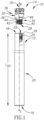
- the face-milling assembly 10 comprises a shank 12 and a head 14.
- the shank 12 comprises a shank rear face 16, a shank front face 18 and a shank peripheral surface 20.
- the shank front face 18 can be formed with an opening 22.
- the opening 22 can be centrally located.
- the opening 22 can be formed with an internal threading 24.
- the shank front face 18 can further comprise a forwardly facing shank annular surface 26.
- the shank annular surface 26 can surround the opening 22.
- the shank can have shank axis As, along which a shank length L SH can be measured.
- the shank length L SH can be configured with a standard length for being held by a collet (not shown).
- the head 14 can comprise a head rear face 28, a head front face 30 and a head peripheral surface 32 extending from the head rear face 28 to the head front face 30.
- the head 14 further comprises a shank-connector portion 34 and a cutting portion 36.
- the shank-connector portion 34 can extend from the rear face 28 to an intersection 38 of the shank-connector portion 34 and cutting portion 36.
- the shank-connector portion 34 can be formed with external threading 40. More precisely the shank-connector portion 34 can comprise a lower connector section 42 and an upper connector section 44. The upper connector section 44 can connect the lower connector section 42 and the cutting portion 36. The external threading 40 can be formed on the lower connector section 42. The upper connector section 44 can preferably be frustoconical.
- the cutting portion 36 can comprise a cutting portion annular surface 46 surrounding the shank-connector 34. More precisely, the cutting portion annular surface 46 surrounds the shank-connector 34 at the intersection 38.
- the head 14 can be secured to the shank 12 via the internal and external threadings 24, 40, with the shank annular surface 26 abutting the cutting portion annular surface 46.
- a central rotation axis A R extends longitudinally through the center of the head 14, defining opposite axially forward and rearward directions D F , D R and opposite rotational preceding and succeeding directions D P , D S , the preceding direction D P being the cutting direction.
- An example inward direction Di is shown for understanding, but it will be understood that the term “inward direction” means generally directed toward the central rotation axis A R .
- an outward direction Do is also exemplified, and should be understood as generally directed away from the central rotation axis A R .
- combined directions such as “forward-inward direction” and “rearward-inward direction” are used, which define a single direction resulting from a combination of components of both of the mentioned directions, although not necessarily an exact bisector between the two mentioned directions.
- a perpendicular plane P P is located at the head front face 30 (i.e. extending at an intersecting a front point thereof, which in this case is constituted by the inner corners 60, the first front corner being designated 60A for explanation hereinafter) and extends perpendicular to the central rotation axis A R .
- a cutting portion length Lc is measurable parallel to the central rotation axis A R . More precisely, the cutting portion length Lc can be defined as extending from the intersection 38 to the head front face 30 (or, stated differently, to the perpendicular plane P P ).
- a shank-connector length Ls is measurable parallel to the central rotation axis A R . More precisely, the shank-connector length Ls can be defined as extending from the rear face 28 to the intersection 38.
- a shank-connector diameter D SC (i.e. a maximum shank-connector diameter) can be smaller than a cutting portion diameter D E measurable perpendicular to the central rotation axis A R .
- the shank-connector diameter Dsc can be smaller than a smallest outer diameter D M of the cutting portion 36.
- a total length L T can be defined from the head rear face 28 to the perpendicular plane Pp.
- the cutting portion 36 comprises a plurality of integrally formed teeth 50 (e.g. first, second, third, fourth, fifth, and sixth teeth 50A, 50B, 50C, 50D, 50E, 50F) and a plurality of flutes 52 (e.g. first, second, third, fourth, fifth, and sixth flutes 52A, 52B, 52C, 52D, 52E, 52F) alternating with the plurality of teeth 50.
- teeth 50 e.g. first, second, third, fourth, fifth, and sixth teeth 50A, 50B, 50C, 50D, 50E, 50F
- flutes 52 e.g. first, second, third, fourth, fifth, and sixth flutes 52A, 52B, 52C, 52D, 52E, 52F
- teeth 50 and flutes 52 can be identical as shown, therefore a description below relating to any tooth or flute should be considered as relating to all.
- the first tooth 50A can comprise a relief edge 54A, a convexly curved outer corner 56A, a primary cutting edge 58A, a convexly curved inner corner 60A, and a ramping cutting edge 62A.
- the relief edge 54A can extend along the peripheral surface 32.
- the relief edge 54A can extend in a rearward-inward direction D R , D I from the outer corner 56A.
- the outer corner 56A can be connected to the relief edge 54A and comprises a radial extremity point 57A ( Fig. 3 ) of the cutting portion 36.
- An outer corner radius Roc can have a preferred yet exemplary value of 0.6mm.
- the primary cutting edge 58A can be connected to the outer corner 56A and can extend in a forward-inward direction D F , D I from the outer corner 56A.
- a preferred yet exemplary value of a cutting edge radius R CE thereof can be 10mm.
- the inner corner 60A can be connected to the primary cutting edge 58A.
- the ramping cutting edge 62A can be connected to inner corner 60A and can extend in a rearward-inward direction D F , D I from the inner corner 60A.
- a first connection point 64A ( Fig. 3 ) can be defined where the primary cutting edge 58A and the inner corner 60A connect
- a second connection point 64B can be defined where the primary cutting edge 58A and the outer corner 56A connect.
- An imaginary straight line Li can be defined between the first and second connection points 64A, 64B and together with the perpendicular plane P P can subtend a cutting angle ⁇ .
- the cutting edge radius R CE is so large that the primary cutting edge 58A essentially overlaps with the imaginary straight line Li.
- An effective cutting length L E can be defined from the second connection point 64B to the perpendicular plane P P .
- Each tooth 50 can be positioned front-of-center as shown.
- a head 14 can be rotated until a radial line L R intersects an intersection point Pi of a primary cutting edge 58A, as is shown in this case for the first tooth 50A.
- the intersection point Pr coincides with the start of the intended main cutting edge, i.e. the second connection point 64B.
- the primary cutting edge 58A is in front of the radial line L R in the preceding direction D P (i.e. the cutting direction).
- the basic direction being schematically shown by the arrow designated 66 (which is directed more towards the outward direction Do than the inward direction Dr).
- a coolant hole 68 can open out to the front face 30.
- coolant exiting the coolant hole 68 flows through adjacent teeth (e.g. in the direction shown by arrow 69) which can further assist ejection of chips (not shown) already propelled in the direction shown by arrow 66.
- helix angle H is shown. While the helix angle values for this type of head are not limited, a preferential range would fulfil the condition 10° ⁇ H ⁇ 30°. With values closer to 20° being considered more preferred.
- the head 14 is configured with a fastening construction 70 along the peripheral surface 32.
- the exemplary fastening construction 70 comprises two identical flat recesses 72 on opposite sides of the head 14 (only one of which being shown) which are configured for engagement with a spanner (not shown).
- the head 14 can be lengthened to a greater cutting portion length Lc than would strictly speaking be required for heat or machining purposes (i.e. such elongation being instead for ease of mounting the head 14 to the shank 12).
Landscapes
- Engineering & Computer Science (AREA)
- Mechanical Engineering (AREA)
- Milling Processes (AREA)
- Dental Tools And Instruments Or Auxiliary Dental Instruments (AREA)
Applications Claiming Priority (2)
| Application Number | Priority Date | Filing Date | Title |
|---|---|---|---|
| US15/096,806 US10335871B2 (en) | 2016-04-12 | 2016-04-12 | Replaceable face-milling head with integrally formed threaded shank-connector |
| PCT/IL2017/050379 WO2017179037A1 (en) | 2016-04-12 | 2017-03-27 | Replaceable face-milling head with integrally formed threaded shank-connector |
Publications (2)
| Publication Number | Publication Date |
|---|---|
| EP3442735A1 EP3442735A1 (en) | 2019-02-20 |
| EP3442735B1 true EP3442735B1 (en) | 2023-09-20 |
Family
ID=58640946
Family Applications (1)
| Application Number | Title | Priority Date | Filing Date |
|---|---|---|---|
| EP17720236.3A Active EP3442735B1 (en) | 2016-04-12 | 2017-03-27 | Replaceable face-milling head with integrally formed threaded shank-connector |
Country Status (14)
| Country | Link |
|---|---|
| US (1) | US10335871B2 (enExample) |
| EP (1) | EP3442735B1 (enExample) |
| JP (1) | JP6993344B2 (enExample) |
| KR (1) | KR102349807B1 (enExample) |
| CN (1) | CN108883479B (enExample) |
| BR (1) | BR112018069775B1 (enExample) |
| CA (1) | CA3019174C (enExample) |
| ES (1) | ES2959831T3 (enExample) |
| IL (1) | IL261931B (enExample) |
| PL (1) | PL3442735T3 (enExample) |
| PT (1) | PT3442735T (enExample) |
| RU (1) | RU2727632C2 (enExample) |
| TW (1) | TWI729113B (enExample) |
| WO (1) | WO2017179037A1 (enExample) |
Families Citing this family (12)
| Publication number | Priority date | Publication date | Assignee | Title |
|---|---|---|---|---|
| WO2013175478A2 (en) | 2012-05-24 | 2013-11-28 | Gershon System Ltd. | Method for designing a cutting edge of a cutting tool, cutting tools comprising the same, and cutting elements with multiple such cutting portions |
| JP6056611B2 (ja) * | 2013-03-29 | 2017-01-11 | 三菱マテリアル株式会社 | 交換式切削ヘッド |
| WO2015040615A1 (en) * | 2013-09-17 | 2015-03-26 | Gershon System Ltd. | Cutting element and a method of cutting using the same |
| EP3042729B1 (en) * | 2015-01-12 | 2021-03-10 | Sandvik Intellectual Property AB | Ceramic milling cutter |
| DE102015214434A1 (de) * | 2015-07-29 | 2017-02-02 | Franz Haimer Maschinenbau Kg | Rotierbares Zerspan-Werkzeug und Schlüssel hierfür |
| WO2020063006A1 (zh) * | 2018-09-25 | 2020-04-02 | 汇专科技集团股份有限公司 | 一种用于加工硬脆性难加工材料的金刚石切削刀具 |
| US11420272B2 (en) * | 2019-01-08 | 2022-08-23 | Iscar, Ltd. | Milling head having integrally formed cutting edges and rotary milling tool |
| DE102019114704A1 (de) * | 2019-05-31 | 2020-12-03 | Hofmann & Vratny Ohg | Fräswerkzeug mit Innenkühlung |
| US11446746B2 (en) | 2019-12-10 | 2022-09-20 | Iscar, Ltd. | Replaceable cutting head having back-tapered conical external thread and rotary cutting tool |
| CN110899808A (zh) * | 2019-12-18 | 2020-03-24 | 株洲钻石切削刀具股份有限公司 | 一种切削刀具 |
| US11376676B2 (en) | 2020-07-07 | 2022-07-05 | Iscar, Ltd. | Rotary cutting head having cutting edges extending past key actuating portion |
| US11426803B2 (en) * | 2020-09-08 | 2022-08-30 | Iscar, Ltd. | Replaceable cutting head having external thread with concavely curved root and rotary cutting tool |
Citations (17)
| Publication number | Priority date | Publication date | Assignee | Title |
|---|---|---|---|---|
| JPH0596415A (ja) | 1991-10-03 | 1993-04-20 | Hitachi Tool Eng Ltd | ボールエンドミル |
| EP0638384A1 (en) | 1993-08-15 | 1995-02-15 | Iscar Ltd. | A cutting insert |
| EP1310313A1 (en) | 2001-11-13 | 2003-05-14 | Sandvik Aktiebolag | Rotatable tool for chip removing machining |
| WO2005089991A1 (en) | 2004-03-12 | 2005-09-29 | Sandvik Intellectual Property Ab | Cutting tool and method for cutting material |
| WO2006033616A1 (en) | 2004-09-24 | 2006-03-30 | Seco Tools Ab | Cutting tip and tool with a frustoconical mounting portion |
| EP1972399A1 (de) | 2007-03-23 | 2008-09-24 | Gühring OHG | Kugelbahnfraeser, Werkzeugsystem mit einem Kugelbahnfraeser sowie Verfahren zur Anbringung eines Kugelbahnfraesers |
| WO2010047428A1 (en) | 2008-10-20 | 2010-04-29 | Taegutec Ltd. | An end mill and a cutting insert used for the same |
| DE102009012433A1 (de) | 2009-03-10 | 2010-09-16 | Kennametal Inc. | Zerspanungswerkzeug für eine Werkzeugmaschine |
| WO2011006804A2 (de) | 2009-07-16 | 2011-01-20 | Hartmetall-Werkzeugfabrik Paul Horn Gmbh | Zweiteiliges werkzeug für spanende bearbeitung mit schraubkupplung |
| DE102010004526A1 (de) | 2010-01-14 | 2011-07-21 | KENNAMETAL INC., Pa. | Zerspanungswerkzeug |
| DE102011012140A1 (de) | 2011-02-24 | 2012-08-30 | Kennametal Inc. | Fräser, insbesondere Kugelschaftfräser |
| DE102012100976A1 (de) | 2012-02-07 | 2013-08-08 | Franz Haimer Maschinenbau Kg | Einschraubwerkzeug und Werkzeugaufnahme für ein derartiges Einschraubwerkzeug |
| EP2650069A2 (en) | 2012-04-11 | 2013-10-16 | Sandvik Intellectual Property AB | Cutting head with coolant channel |
| EP2769791A1 (en) | 2011-10-17 | 2014-08-27 | Mitsubishi Materials Corporation | Head replacement-type cutting tool |
| WO2015058881A1 (de) | 2013-10-21 | 2015-04-30 | Walter Ag | Schaftfräser für warmfeste superlegierungen |
| DE112013005984T5 (de) | 2012-12-13 | 2015-10-15 | Iscar Ltd. | Schneidwerkzeug und austauschbarer Schneidkopf mit spiralförmig angetriebenen Flächen dafür |
| DE102015106082A1 (de) | 2014-04-24 | 2015-10-29 | Kennametal India Ltd. | Schneidwerkzeug mit auswechselbarem Schneideinsatz und geneigten Befestigungselementen |
Family Cites Families (35)
| Publication number | Priority date | Publication date | Assignee | Title |
|---|---|---|---|---|
| US756339A (en) * | 1903-11-14 | 1904-04-05 | William R Down | Composite drill. |
| US4438953A (en) * | 1981-02-27 | 1984-03-27 | Hughes Tool Company | Tool joint bench mark |
| US5094573A (en) * | 1988-07-21 | 1992-03-10 | Hougen Everett D | Multidirectional cutting tool |
| SE509218C2 (sv) * | 1994-08-29 | 1998-12-21 | Sandvik Ab | Skaftverktyg |
| US6056485A (en) * | 1998-09-01 | 2000-05-02 | Kennametal Inc. | Ramp plunge and feed milling cutter |
| IL136032A (en) * | 2000-05-09 | 2003-12-10 | Iscar Ltd | Tool joint |
| IL137316A (en) | 2000-07-16 | 2004-01-04 | Iscar Ltd | Cutting Tools |
| IL162147A (en) * | 2004-05-24 | 2008-03-20 | Gil Hecht | Drill with interchangeable head |
| SE527703C2 (sv) * | 2004-08-19 | 2006-05-16 | Sandvik Intellectual Property | Roterbart verktyg samt skärhuvud med axiella serraterade ingreppsorgan |
| SE528251C2 (sv) * | 2004-09-24 | 2006-10-03 | Seco Tools Ab | Handel för verktyg samt verktyg med ett övergångsparti mellan ett gängat parti och ett stödjande parti |
| RU53199U1 (ru) * | 2005-06-29 | 2006-05-10 | Общество с ограниченной ответственностью "Техноинструмент" | Концевая сменная фреза |
| SE530043C2 (sv) * | 2006-04-20 | 2008-02-12 | Sandvik Intellectual Property | Verktyg för spånavskiljande bearbetning samt del därtill |
| SE532394C2 (sv) * | 2007-06-04 | 2010-01-12 | Sandvik Intellectual Property | Verktyg för spånavskiljande bearbetning samt grundkropp härför |
| FR2920327B1 (fr) * | 2007-08-30 | 2009-11-20 | Snecma | Fraise a rainurer pour usinage a grande avance et a faible profondeur de passe |
| IL191330A (en) * | 2008-05-11 | 2014-11-30 | Kennametal Inc | Component grinding tool with alternating blade |
| US9227253B1 (en) * | 2009-03-30 | 2016-01-05 | Steven M. Swift | Rotary cutter for machining materials |
| CN201439135U (zh) * | 2009-06-03 | 2010-04-21 | 铠钜科技股份有限公司 | 替换式铣刀的复合材料刀头 |
| JP5350149B2 (ja) * | 2009-09-07 | 2013-11-27 | ダイジ▲ェ▼ット工業株式会社 | 切削工具 |
| US9827620B2 (en) * | 2010-09-29 | 2017-11-28 | Mitsubishi Materials Corporation | Head replacement-type cutting tool |
| US8647025B2 (en) | 2011-01-17 | 2014-02-11 | Kennametal Inc. | Monolithic ceramic end mill |
| RU111472U1 (ru) * | 2011-05-06 | 2011-12-20 | Государственное образовательное учреждение высшего профессионального образования "Алтайский государственный технический университет им. И.И. Ползунова" (АлтГТУ) | Узел крепления сменных модулей блочной инструментальной оснастки |
| ITFI20110153A1 (it) * | 2011-07-25 | 2013-01-26 | Nuovo Pignone Spa | "cutting tool" |
| JP5664506B2 (ja) * | 2011-09-09 | 2015-02-04 | 三菱マテリアル株式会社 | ヘッド交換式切削工具 |
| EP2769792B1 (en) * | 2011-10-17 | 2020-01-08 | Mitsubishi Materials Corporation | Holder for head replacement-type cutting tool, and head replacement-type cutting tool |
| US9802256B2 (en) * | 2012-02-07 | 2017-10-31 | Franz Haimer Maschinenbau Kg | Screw-in tool and tool holder for such a screw-in tool |
| EP2832481A4 (en) * | 2012-03-29 | 2015-08-12 | Hitachi Tool Eng | MACHINE HEAD, HOLDER AND CUTTING TOOL WITH REPLACEABLE TIP |
| DE102012107546A1 (de) * | 2012-08-17 | 2014-02-20 | Franz Haimer Maschinenbau Kg | Werkzeuganordnung |
| US20140056658A1 (en) * | 2012-08-24 | 2014-02-27 | Sumitomo Electric Hardmetal Corp. | Cutting tool with removable head |
| DE102013100939A1 (de) * | 2013-01-30 | 2014-07-31 | Franz Haimer Maschinenbau Kg | Werkzeugaufnahme für ein Einschraubwerkzeug |
| US20140356081A1 (en) * | 2013-05-30 | 2014-12-04 | Kennametal Inc. | End mill with high ramp angle capability |
| CN203484723U (zh) * | 2013-10-11 | 2014-03-19 | 中航飞机股份有限公司西安飞机分公司 | 一种组合式数控铣刀 |
| US9381583B2 (en) * | 2014-02-12 | 2016-07-05 | Kennametal Inc. | Prismatic and cylindrical cutting inserts |
| US20150258616A1 (en) * | 2014-03-11 | 2015-09-17 | Frank J Stanbach | End mill |
| US9889509B2 (en) * | 2014-05-05 | 2018-02-13 | Kennametal Inc. | Cutter heads with improved coupling |
| US10105771B2 (en) * | 2016-03-21 | 2018-10-23 | Iscar, Ltd. | Rotary cutting tool having tool holder with conical internal thread and replaceable cutting head with straight external thread, and said tool holder |
-
2016
- 2016-04-12 US US15/096,806 patent/US10335871B2/en active Active
-
2017
- 2017-03-27 RU RU2018139518A patent/RU2727632C2/ru active
- 2017-03-27 KR KR1020187029307A patent/KR102349807B1/ko active Active
- 2017-03-27 CA CA3019174A patent/CA3019174C/en active Active
- 2017-03-27 ES ES17720236T patent/ES2959831T3/es active Active
- 2017-03-27 PL PL17720236.3T patent/PL3442735T3/pl unknown
- 2017-03-27 JP JP2018545190A patent/JP6993344B2/ja active Active
- 2017-03-27 WO PCT/IL2017/050379 patent/WO2017179037A1/en not_active Ceased
- 2017-03-27 BR BR112018069775-3A patent/BR112018069775B1/pt active IP Right Grant
- 2017-03-27 PT PT177202363T patent/PT3442735T/pt unknown
- 2017-03-27 CN CN201780023279.7A patent/CN108883479B/zh active Active
- 2017-03-27 EP EP17720236.3A patent/EP3442735B1/en active Active
- 2017-04-10 TW TW106111895A patent/TWI729113B/zh active
-
2018
- 2018-09-25 IL IL261931A patent/IL261931B/en unknown
Patent Citations (17)
| Publication number | Priority date | Publication date | Assignee | Title |
|---|---|---|---|---|
| JPH0596415A (ja) | 1991-10-03 | 1993-04-20 | Hitachi Tool Eng Ltd | ボールエンドミル |
| EP0638384A1 (en) | 1993-08-15 | 1995-02-15 | Iscar Ltd. | A cutting insert |
| EP1310313A1 (en) | 2001-11-13 | 2003-05-14 | Sandvik Aktiebolag | Rotatable tool for chip removing machining |
| WO2005089991A1 (en) | 2004-03-12 | 2005-09-29 | Sandvik Intellectual Property Ab | Cutting tool and method for cutting material |
| WO2006033616A1 (en) | 2004-09-24 | 2006-03-30 | Seco Tools Ab | Cutting tip and tool with a frustoconical mounting portion |
| EP1972399A1 (de) | 2007-03-23 | 2008-09-24 | Gühring OHG | Kugelbahnfraeser, Werkzeugsystem mit einem Kugelbahnfraeser sowie Verfahren zur Anbringung eines Kugelbahnfraesers |
| WO2010047428A1 (en) | 2008-10-20 | 2010-04-29 | Taegutec Ltd. | An end mill and a cutting insert used for the same |
| DE102009012433A1 (de) | 2009-03-10 | 2010-09-16 | Kennametal Inc. | Zerspanungswerkzeug für eine Werkzeugmaschine |
| WO2011006804A2 (de) | 2009-07-16 | 2011-01-20 | Hartmetall-Werkzeugfabrik Paul Horn Gmbh | Zweiteiliges werkzeug für spanende bearbeitung mit schraubkupplung |
| DE102010004526A1 (de) | 2010-01-14 | 2011-07-21 | KENNAMETAL INC., Pa. | Zerspanungswerkzeug |
| DE102011012140A1 (de) | 2011-02-24 | 2012-08-30 | Kennametal Inc. | Fräser, insbesondere Kugelschaftfräser |
| EP2769791A1 (en) | 2011-10-17 | 2014-08-27 | Mitsubishi Materials Corporation | Head replacement-type cutting tool |
| DE102012100976A1 (de) | 2012-02-07 | 2013-08-08 | Franz Haimer Maschinenbau Kg | Einschraubwerkzeug und Werkzeugaufnahme für ein derartiges Einschraubwerkzeug |
| EP2650069A2 (en) | 2012-04-11 | 2013-10-16 | Sandvik Intellectual Property AB | Cutting head with coolant channel |
| DE112013005984T5 (de) | 2012-12-13 | 2015-10-15 | Iscar Ltd. | Schneidwerkzeug und austauschbarer Schneidkopf mit spiralförmig angetriebenen Flächen dafür |
| WO2015058881A1 (de) | 2013-10-21 | 2015-04-30 | Walter Ag | Schaftfräser für warmfeste superlegierungen |
| DE102015106082A1 (de) | 2014-04-24 | 2015-10-29 | Kennametal India Ltd. | Schneidwerkzeug mit auswechselbarem Schneideinsatz und geneigten Befestigungselementen |
Non-Patent Citations (2)
| Title |
|---|
| ANONYMOUS: "Multi Master Indexable Solid Carbide Line", ISCAR, 1 January 2013 (2013-01-01), XP093194423, Retrieved from the Internet <URL:https://www.iscar.com/Catalogs/publication-2016/Multi%20Master.pdf> |
| ANONYMOUS: "Printing registration", WIKIPEDIA, 4 December 2022 (2022-12-04), XP093194418, Retrieved from the Internet <URL:https://en.wikipedia.org/w/index.php?title=Printing_registration&oldid=1125479739> |
Also Published As
| Publication number | Publication date |
|---|---|
| PL3442735T3 (pl) | 2024-03-04 |
| IL261931A (en) | 2018-10-31 |
| KR20180126509A (ko) | 2018-11-27 |
| CN108883479B (zh) | 2020-07-10 |
| CA3019174C (en) | 2024-01-02 |
| KR102349807B1 (ko) | 2022-01-12 |
| CN108883479A (zh) | 2018-11-23 |
| RU2018139518A3 (enExample) | 2020-06-03 |
| EP3442735A1 (en) | 2019-02-20 |
| TW201739548A (zh) | 2017-11-16 |
| US20170291230A1 (en) | 2017-10-12 |
| US10335871B2 (en) | 2019-07-02 |
| BR112018069775B1 (pt) | 2022-07-12 |
| CA3019174A1 (en) | 2017-10-19 |
| JP2019515801A (ja) | 2019-06-13 |
| BR112018069775A2 (pt) | 2019-02-05 |
| JP6993344B2 (ja) | 2022-01-13 |
| RU2018139518A (ru) | 2020-05-12 |
| ES2959831T3 (es) | 2024-02-28 |
| IL261931B (en) | 2021-12-01 |
| TWI729113B (zh) | 2021-06-01 |
| RU2727632C2 (ru) | 2020-07-22 |
| WO2017179037A1 (en) | 2017-10-19 |
| PT3442735T (pt) | 2023-10-16 |
Similar Documents
| Publication | Publication Date | Title |
|---|---|---|
| EP3442735B1 (en) | Replaceable face-milling head with integrally formed threaded shank-connector | |
| EP2650069B1 (en) | Cutting head with coolant channel and method of forming such a cutting head | |
| JP6337112B2 (ja) | 切削インサート、切削工具及び切削加工物の製造方法 | |
| EP2012958B2 (en) | Face milling cutter | |
| JP5614511B2 (ja) | ボールエンドミル及びインサート | |
| CN111093867B (zh) | 用于金属切削的车削刀具 | |
| CN110382148A (zh) | 刀尖 | |
| SE1050877A1 (sv) | Skär med radieparti, verktyg och anordning för fräsning | |
| WO2021200400A1 (ja) | 刃先交換式切削工具および工具本体 | |
| US20220203464A1 (en) | Milling tool with coolant distributing holes | |
| US10792738B2 (en) | Cutting tool and method of manufacturing machined product | |
| JP2008023632A (ja) | 切削工具及びインサート | |
| JP2021160023A (ja) | 刃先交換式切削工具および工具本体 | |
| JP2021160021A (ja) | 刃先交換式切削工具および工具本体 |
Legal Events
| Date | Code | Title | Description |
|---|---|---|---|
| STAA | Information on the status of an ep patent application or granted ep patent |
Free format text: STATUS: UNKNOWN |
|
| STAA | Information on the status of an ep patent application or granted ep patent |
Free format text: STATUS: THE INTERNATIONAL PUBLICATION HAS BEEN MADE |
|
| PUAI | Public reference made under article 153(3) epc to a published international application that has entered the european phase |
Free format text: ORIGINAL CODE: 0009012 |
|
| STAA | Information on the status of an ep patent application or granted ep patent |
Free format text: STATUS: REQUEST FOR EXAMINATION WAS MADE |
|
| 17P | Request for examination filed |
Effective date: 20181015 |
|
| AK | Designated contracting states |
Kind code of ref document: A1 Designated state(s): AL AT BE BG CH CY CZ DE DK EE ES FI FR GB GR HR HU IE IS IT LI LT LU LV MC MK MT NL NO PL PT RO RS SE SI SK SM TR |
|
| AX | Request for extension of the european patent |
Extension state: BA ME |
|
| DAV | Request for validation of the european patent (deleted) | ||
| DAX | Request for extension of the european patent (deleted) | ||
| GRAP | Despatch of communication of intention to grant a patent |
Free format text: ORIGINAL CODE: EPIDOSNIGR1 |
|
| STAA | Information on the status of an ep patent application or granted ep patent |
Free format text: STATUS: GRANT OF PATENT IS INTENDED |
|
| INTG | Intention to grant announced |
Effective date: 20220704 |
|
| GRAJ | Information related to disapproval of communication of intention to grant by the applicant or resumption of examination proceedings by the epo deleted |
Free format text: ORIGINAL CODE: EPIDOSDIGR1 |
|
| STAA | Information on the status of an ep patent application or granted ep patent |
Free format text: STATUS: REQUEST FOR EXAMINATION WAS MADE |
|
| INTC | Intention to grant announced (deleted) | ||
| GRAP | Despatch of communication of intention to grant a patent |
Free format text: ORIGINAL CODE: EPIDOSNIGR1 |
|
| STAA | Information on the status of an ep patent application or granted ep patent |
Free format text: STATUS: GRANT OF PATENT IS INTENDED |
|
| INTG | Intention to grant announced |
Effective date: 20230124 |
|
| GRAJ | Information related to disapproval of communication of intention to grant by the applicant or resumption of examination proceedings by the epo deleted |
Free format text: ORIGINAL CODE: EPIDOSDIGR1 |
|
| STAA | Information on the status of an ep patent application or granted ep patent |
Free format text: STATUS: REQUEST FOR EXAMINATION WAS MADE |
|
| P01 | Opt-out of the competence of the unified patent court (upc) registered |
Effective date: 20230426 |
|
| INTC | Intention to grant announced (deleted) | ||
| GRAS | Grant fee paid |
Free format text: ORIGINAL CODE: EPIDOSNIGR3 |
|
| STAA | Information on the status of an ep patent application or granted ep patent |
Free format text: STATUS: GRANT OF PATENT IS INTENDED |
|
| GRAP | Despatch of communication of intention to grant a patent |
Free format text: ORIGINAL CODE: EPIDOSNIGR1 |
|
| GRAA | (expected) grant |
Free format text: ORIGINAL CODE: 0009210 |
|
| STAA | Information on the status of an ep patent application or granted ep patent |
Free format text: STATUS: THE PATENT HAS BEEN GRANTED |
|
| INTG | Intention to grant announced |
Effective date: 20230724 |
|
| AK | Designated contracting states |
Kind code of ref document: B1 Designated state(s): AL AT BE BG CH CY CZ DE DK EE ES FI FR GB GR HR HU IE IS IT LI LT LU LV MC MK MT NL NO PL PT RO RS SE SI SK SM TR |
|
| REG | Reference to a national code |
Ref country code: GB Ref legal event code: FG4D |
|
| REG | Reference to a national code |
Ref country code: CH Ref legal event code: EP |
|
| REG | Reference to a national code |
Ref country code: IE Ref legal event code: FG4D |
|
| REG | Reference to a national code |
Ref country code: DE Ref legal event code: R096 Ref document number: 602017074394 Country of ref document: DE |
|
| REG | Reference to a national code |
Ref country code: PT Ref legal event code: SC4A Ref document number: 3442735 Country of ref document: PT Date of ref document: 20231016 Kind code of ref document: T Free format text: AVAILABILITY OF NATIONAL TRANSLATION Effective date: 20231009 |
|
| REG | Reference to a national code |
Ref country code: SE Ref legal event code: TRGR |
|
| REG | Reference to a national code |
Ref country code: LT Ref legal event code: MG9D |
|
| PG25 | Lapsed in a contracting state [announced via postgrant information from national office to epo] |
Ref country code: GR Free format text: LAPSE BECAUSE OF FAILURE TO SUBMIT A TRANSLATION OF THE DESCRIPTION OR TO PAY THE FEE WITHIN THE PRESCRIBED TIME-LIMIT Effective date: 20231221 |
|
| REG | Reference to a national code |
Ref country code: NL Ref legal event code: MP Effective date: 20230920 |
|
| PG25 | Lapsed in a contracting state [announced via postgrant information from national office to epo] |
Ref country code: RS Free format text: LAPSE BECAUSE OF FAILURE TO SUBMIT A TRANSLATION OF THE DESCRIPTION OR TO PAY THE FEE WITHIN THE PRESCRIBED TIME-LIMIT Effective date: 20230920 Ref country code: NO Free format text: LAPSE BECAUSE OF FAILURE TO SUBMIT A TRANSLATION OF THE DESCRIPTION OR TO PAY THE FEE WITHIN THE PRESCRIBED TIME-LIMIT Effective date: 20231220 Ref country code: LV Free format text: LAPSE BECAUSE OF FAILURE TO SUBMIT A TRANSLATION OF THE DESCRIPTION OR TO PAY THE FEE WITHIN THE PRESCRIBED TIME-LIMIT Effective date: 20230920 Ref country code: LT Free format text: LAPSE BECAUSE OF FAILURE TO SUBMIT A TRANSLATION OF THE DESCRIPTION OR TO PAY THE FEE WITHIN THE PRESCRIBED TIME-LIMIT Effective date: 20230920 Ref country code: HR Free format text: LAPSE BECAUSE OF FAILURE TO SUBMIT A TRANSLATION OF THE DESCRIPTION OR TO PAY THE FEE WITHIN THE PRESCRIBED TIME-LIMIT Effective date: 20230920 Ref country code: GR Free format text: LAPSE BECAUSE OF FAILURE TO SUBMIT A TRANSLATION OF THE DESCRIPTION OR TO PAY THE FEE WITHIN THE PRESCRIBED TIME-LIMIT Effective date: 20231221 Ref country code: FI Free format text: LAPSE BECAUSE OF FAILURE TO SUBMIT A TRANSLATION OF THE DESCRIPTION OR TO PAY THE FEE WITHIN THE PRESCRIBED TIME-LIMIT Effective date: 20230920 |
|
| REG | Reference to a national code |
Ref country code: AT Ref legal event code: UEP Ref document number: 1613039 Country of ref document: AT Kind code of ref document: T Effective date: 20230920 |
|
| REG | Reference to a national code |
Ref country code: ES Ref legal event code: FG2A Ref document number: 2959831 Country of ref document: ES Kind code of ref document: T3 Effective date: 20240228 |
|
| PG25 | Lapsed in a contracting state [announced via postgrant information from national office to epo] |
Ref country code: NL Free format text: LAPSE BECAUSE OF FAILURE TO SUBMIT A TRANSLATION OF THE DESCRIPTION OR TO PAY THE FEE WITHIN THE PRESCRIBED TIME-LIMIT Effective date: 20230920 |
|
| PG25 | Lapsed in a contracting state [announced via postgrant information from national office to epo] |
Ref country code: IS Free format text: LAPSE BECAUSE OF FAILURE TO SUBMIT A TRANSLATION OF THE DESCRIPTION OR TO PAY THE FEE WITHIN THE PRESCRIBED TIME-LIMIT Effective date: 20240120 |
|
| PG25 | Lapsed in a contracting state [announced via postgrant information from national office to epo] |
Ref country code: SM Free format text: LAPSE BECAUSE OF FAILURE TO SUBMIT A TRANSLATION OF THE DESCRIPTION OR TO PAY THE FEE WITHIN THE PRESCRIBED TIME-LIMIT Effective date: 20230920 Ref country code: RO Free format text: LAPSE BECAUSE OF FAILURE TO SUBMIT A TRANSLATION OF THE DESCRIPTION OR TO PAY THE FEE WITHIN THE PRESCRIBED TIME-LIMIT Effective date: 20230920 Ref country code: IS Free format text: LAPSE BECAUSE OF FAILURE TO SUBMIT A TRANSLATION OF THE DESCRIPTION OR TO PAY THE FEE WITHIN THE PRESCRIBED TIME-LIMIT Effective date: 20240120 Ref country code: EE Free format text: LAPSE BECAUSE OF FAILURE TO SUBMIT A TRANSLATION OF THE DESCRIPTION OR TO PAY THE FEE WITHIN THE PRESCRIBED TIME-LIMIT Effective date: 20230920 Ref country code: SK Free format text: LAPSE BECAUSE OF FAILURE TO SUBMIT A TRANSLATION OF THE DESCRIPTION OR TO PAY THE FEE WITHIN THE PRESCRIBED TIME-LIMIT Effective date: 20230920 |
|
| PLBI | Opposition filed |
Free format text: ORIGINAL CODE: 0009260 |
|
| REG | Reference to a national code |
Ref country code: DE Ref legal event code: R026 Ref document number: 602017074394 Country of ref document: DE |
|
| PLAB | Opposition data, opponent's data or that of the opponent's representative modified |
Free format text: ORIGINAL CODE: 0009299OPPO |
|
| PLAX | Notice of opposition and request to file observation + time limit sent |
Free format text: ORIGINAL CODE: EPIDOSNOBS2 |
|
| PG25 | Lapsed in a contracting state [announced via postgrant information from national office to epo] |
Ref country code: DK Free format text: LAPSE BECAUSE OF FAILURE TO SUBMIT A TRANSLATION OF THE DESCRIPTION OR TO PAY THE FEE WITHIN THE PRESCRIBED TIME-LIMIT Effective date: 20230920 |
|
| 26 | Opposition filed |
Opponent name: SPACHMANN, HOLGER Effective date: 20240620 |
|
| PG25 | Lapsed in a contracting state [announced via postgrant information from national office to epo] |
Ref country code: DK Free format text: LAPSE BECAUSE OF FAILURE TO SUBMIT A TRANSLATION OF THE DESCRIPTION OR TO PAY THE FEE WITHIN THE PRESCRIBED TIME-LIMIT Effective date: 20230920 |
|
| R26 | Opposition filed (corrected) |
Opponent name: SPACHMANN, HOLGER Effective date: 20240620 |
|
| PG25 | Lapsed in a contracting state [announced via postgrant information from national office to epo] |
Ref country code: SI Free format text: LAPSE BECAUSE OF FAILURE TO SUBMIT A TRANSLATION OF THE DESCRIPTION OR TO PAY THE FEE WITHIN THE PRESCRIBED TIME-LIMIT Effective date: 20230920 |
|
| PLAF | Information modified related to communication of a notice of opposition and request to file observations + time limit |
Free format text: ORIGINAL CODE: EPIDOSCOBS2 |
|
| PG25 | Lapsed in a contracting state [announced via postgrant information from national office to epo] |
Ref country code: SI Free format text: LAPSE BECAUSE OF FAILURE TO SUBMIT A TRANSLATION OF THE DESCRIPTION OR TO PAY THE FEE WITHIN THE PRESCRIBED TIME-LIMIT Effective date: 20230920 |
|
| REG | Reference to a national code |
Ref country code: CH Ref legal event code: PL |
|
| PG25 | Lapsed in a contracting state [announced via postgrant information from national office to epo] |
Ref country code: BG Free format text: LAPSE BECAUSE OF FAILURE TO SUBMIT A TRANSLATION OF THE DESCRIPTION OR TO PAY THE FEE WITHIN THE PRESCRIBED TIME-LIMIT Effective date: 20230920 |
|
| PG25 | Lapsed in a contracting state [announced via postgrant information from national office to epo] |
Ref country code: LU Free format text: LAPSE BECAUSE OF NON-PAYMENT OF DUE FEES Effective date: 20240327 |
|
| PG25 | Lapsed in a contracting state [announced via postgrant information from national office to epo] |
Ref country code: MC Free format text: LAPSE BECAUSE OF FAILURE TO SUBMIT A TRANSLATION OF THE DESCRIPTION OR TO PAY THE FEE WITHIN THE PRESCRIBED TIME-LIMIT Effective date: 20230920 |
|
| PG25 | Lapsed in a contracting state [announced via postgrant information from national office to epo] |
Ref country code: MC Free format text: LAPSE BECAUSE OF FAILURE TO SUBMIT A TRANSLATION OF THE DESCRIPTION OR TO PAY THE FEE WITHIN THE PRESCRIBED TIME-LIMIT Effective date: 20230920 Ref country code: LU Free format text: LAPSE BECAUSE OF NON-PAYMENT OF DUE FEES Effective date: 20240327 Ref country code: BG Free format text: LAPSE BECAUSE OF FAILURE TO SUBMIT A TRANSLATION OF THE DESCRIPTION OR TO PAY THE FEE WITHIN THE PRESCRIBED TIME-LIMIT Effective date: 20230920 |
|
| REG | Reference to a national code |
Ref country code: BE Ref legal event code: MM Effective date: 20240331 |
|
| PLBB | Reply of patent proprietor to notice(s) of opposition received |
Free format text: ORIGINAL CODE: EPIDOSNOBS3 |
|
| PG25 | Lapsed in a contracting state [announced via postgrant information from national office to epo] |
Ref country code: BE Free format text: LAPSE BECAUSE OF NON-PAYMENT OF DUE FEES Effective date: 20240331 |
|
| PG25 | Lapsed in a contracting state [announced via postgrant information from national office to epo] |
Ref country code: IE Free format text: LAPSE BECAUSE OF NON-PAYMENT OF DUE FEES Effective date: 20240327 |
|
| PG25 | Lapsed in a contracting state [announced via postgrant information from national office to epo] |
Ref country code: IE Free format text: LAPSE BECAUSE OF NON-PAYMENT OF DUE FEES Effective date: 20240327 Ref country code: BE Free format text: LAPSE BECAUSE OF NON-PAYMENT OF DUE FEES Effective date: 20240331 Ref country code: CH Free format text: LAPSE BECAUSE OF NON-PAYMENT OF DUE FEES Effective date: 20240331 |
|
| PGFP | Annual fee paid to national office [announced via postgrant information from national office to epo] |
Ref country code: DE Payment date: 20250221 Year of fee payment: 9 Ref country code: PT Payment date: 20250115 Year of fee payment: 9 |
|
| PGFP | Annual fee paid to national office [announced via postgrant information from national office to epo] |
Ref country code: SE Payment date: 20250207 Year of fee payment: 9 |
|
| PGFP | Annual fee paid to national office [announced via postgrant information from national office to epo] |
Ref country code: AT Payment date: 20250207 Year of fee payment: 9 |
|
| PGFP | Annual fee paid to national office [announced via postgrant information from national office to epo] |
Ref country code: PL Payment date: 20250115 Year of fee payment: 9 Ref country code: FR Payment date: 20250217 Year of fee payment: 9 Ref country code: CZ Payment date: 20250114 Year of fee payment: 9 |
|
| PGFP | Annual fee paid to national office [announced via postgrant information from national office to epo] |
Ref country code: IT Payment date: 20250120 Year of fee payment: 9 Ref country code: GB Payment date: 20250221 Year of fee payment: 9 |
|
| PGFP | Annual fee paid to national office [announced via postgrant information from national office to epo] |
Ref country code: TR Payment date: 20250214 Year of fee payment: 9 |
|
| PGFP | Annual fee paid to national office [announced via postgrant information from national office to epo] |
Ref country code: ES Payment date: 20250424 Year of fee payment: 9 |
|
| PG25 | Lapsed in a contracting state [announced via postgrant information from national office to epo] |
Ref country code: CY Free format text: LAPSE BECAUSE OF FAILURE TO SUBMIT A TRANSLATION OF THE DESCRIPTION OR TO PAY THE FEE WITHIN THE PRESCRIBED TIME-LIMIT; INVALID AB INITIO Effective date: 20170327 |
|
| PG25 | Lapsed in a contracting state [announced via postgrant information from national office to epo] |
Ref country code: HU Free format text: LAPSE BECAUSE OF FAILURE TO SUBMIT A TRANSLATION OF THE DESCRIPTION OR TO PAY THE FEE WITHIN THE PRESCRIBED TIME-LIMIT; INVALID AB INITIO Effective date: 20170327 |