EP3441716A1 - Workpiece supporting device - Google Patents
Workpiece supporting device Download PDFInfo
- Publication number
- EP3441716A1 EP3441716A1 EP17779041.7A EP17779041A EP3441716A1 EP 3441716 A1 EP3441716 A1 EP 3441716A1 EP 17779041 A EP17779041 A EP 17779041A EP 3441716 A1 EP3441716 A1 EP 3441716A1
- Authority
- EP
- European Patent Office
- Prior art keywords
- workpiece
- arm
- fulcrums
- center
- supporting device
- Prior art date
- Legal status (The legal status is an assumption and is not a legal conclusion. Google has not performed a legal analysis and makes no representation as to the accuracy of the status listed.)
- Granted
Links
Images







Classifications
-
- G—PHYSICS
- G01—MEASURING; TESTING
- G01B—MEASURING LENGTH, THICKNESS OR SIMILAR LINEAR DIMENSIONS; MEASURING ANGLES; MEASURING AREAS; MEASURING IRREGULARITIES OF SURFACES OR CONTOURS
- G01B5/00—Measuring arrangements characterised by the use of mechanical techniques
- G01B5/0011—Arrangements for eliminating or compensation of measuring errors due to temperature or weight
- G01B5/0016—Arrangements for eliminating or compensation of measuring errors due to temperature or weight due to weight
-
- G—PHYSICS
- G01—MEASURING; TESTING
- G01B—MEASURING LENGTH, THICKNESS OR SIMILAR LINEAR DIMENSIONS; MEASURING ANGLES; MEASURING AREAS; MEASURING IRREGULARITIES OF SURFACES OR CONTOURS
- G01B5/00—Measuring arrangements characterised by the use of mechanical techniques
- G01B5/0002—Arrangements for supporting, fixing or guiding the measuring instrument or the object to be measured
- G01B5/0004—Supports
-
- G—PHYSICS
- G01—MEASURING; TESTING
- G01B—MEASURING LENGTH, THICKNESS OR SIMILAR LINEAR DIMENSIONS; MEASURING ANGLES; MEASURING AREAS; MEASURING IRREGULARITIES OF SURFACES OR CONTOURS
- G01B7/00—Measuring arrangements characterised by the use of electric or magnetic techniques
- G01B7/28—Measuring arrangements characterised by the use of electric or magnetic techniques for measuring contours or curvatures
- G01B7/282—Measuring arrangements characterised by the use of electric or magnetic techniques for measuring contours or curvatures for measuring roundness
Definitions
- the present invention relates to a workpiece supporting device for supporting a workpiece in a shape measuring device (shape meter).
- a shape measuring device for measuring a shape of a workpiece there is known a roundness measuring device for measuring the roundness of a workpiece having a columnar shape or cylindrical shape.
- the detector In the roundness measuring device, in a state where a probe of a detector is brought into contact with a periphery of the workpiece supported on a table, the detector is rotated relatively around the workpiece and measures the roundness of the workpiece.
- such a roundness measuring device supports a bottom surface (plane) of the workpiece at three points on the table (see, e.g., PTL 1 and PTL 2). Further, in a case where a roundness of a large-sized workpiece is measured, it is known that the roundness is measured in a state where the workpiece is set on the reference plane such as a surface plate (level block).
- the reference plane such as a surface plate (level block).
- FIG. 16 are explanation views for explaining a problem of the conventional technique. Note that, in (A) and (B) portions of Figure 16 , the unevenness of the bottom surface of the workpiece 100 is emphasized more than actual size. As shown in (A) portion of Figure 16 , in the case where the workpiece 100 is supported at three points by the three support projections 102 (supporting points) provided on the table 101 of the roundness measuring device, if the workpiece 100 is large, the distance among the support projections 102 is widened, and therefore, the deflection of the workpiece 100 is generated by its own weight (denoted by dotted line in the figure). As a result, the roundness measuring accuracy is degraded.
- the present invention has been implemented in light of such circumstances, and aims to provide a workpiece supporting device which is able to reduce the deflection of the workpiece at a low cost.
- a workpiece supporting device to be provided for a shape measuring device which measures a shape of a workpiece
- the workpiece supporting device including: a horizontal table; three first fulcrums provided on an upper surface of the table; first arms swingably supported by the respective first fulcrums, each of the first arms swingably supported at a central part in a longitudinal direction of the first arm by the first fulcrum; and a plurality of first contacting parts swingably provided on an upper surface of the first arm for each first fulcrum and distributed from the first fulcrum in different directions, the first contacting parts configured to come into contact with the workpiece.
- the workpiece supporting device it is possible to shorten the distance between the first contacting parts (workpiece fulcrums) which support the workpiece and is possible to bring the first contacting parts into contact with the bottom surface of the workpiece in a state where the first contacting parts securely follow the bottom surface of the workpiece.
- positional relation between the first fulcrums satisfies a requirement that a first line segment connects two of the three first fulcrums, a second line segment connects the other one first fulcrum and a center of gravity of the workpiece, and an extension of the second line segment perpendicularly intersects with the first line segment at a midpoint of the first line segment.
- the first fulcrums are provided on the upper surface of the table around a gravity center axis, which passes through a center of gravity of the workpiece and extends perpendicularly to the upper surface of the table, at equal spacing. This makes it possible to uniformly support the workpiece by the first contacting parts.
- the first fulcrums are provided on the upper surface of the table on a concentric circle having a center of gravity of the workpiece as a circle center. This makes it possible to uniformly support the workpiece by the first contacting parts.
- the workpiece supporting device further comprises a guide part configured to movably support the first fulcrums along the upper surface of the table. This makes it possible to support the workpiece having any dimension (size) and shape without exchanging the workpiece supporting device.
- the first fulcrum supports the first arm swingably around an axis which is parallel to a third line segment that connects the first fulcrum and a center of gravity of the workpiece. This makes it possible to bring the first contacting parts into contact with the bottom surface of the workpiece in a state where the first contacting parts securely follow the bottom surface of the workpiece.
- all of the first contacting parts are arranged on a concentric circle having a center of gravity of the workpiece as a circle center. This makes it possible to uniformly support the workpiece by the first contacting parts.
- all of the first contacting parts are distributed on a plurality of concentric circles having diameters different from each other. This makes it possible to support a large workpiece.
- all of the first contacting parts are arranged around a gravity center axis, which passes through a center of gravity of the workpiece and extends perpendicularly to the upper surface of the table, at equal spacing. This makes it possible to uniformly support the workpiece by the first contacting parts.
- the first arm is retractable in the longitudinal direction of the first arm. This makes it possible to support the workpiece having any dimension (size) and shape without exchanging the workpiece supporting device.
- the first contacting part includes: second fulcrums provided on the upper surface of the first arm; second arms swingably supported by the second fulcrums, each of the second arms swingably supported at a central part in a longitudinal direction of the second arm by the second fulcrum; and a plurality of second contacting parts swingably provided on an upper surface of the second arm for each second fulcrum and distributed from the second fulcrum in different directions, the second contacting parts configured to come into contact with the workpiece. It is possible to make the distance between the second contacting parts shorter than the distance between the first contacting parts and therefore it is possible to reduce the deflection of the workpiece caused due to own weight of the workpiece.
- the workpiece supporting device of the present invention is able to reduce the deflection of the workpiece at a low cost.
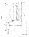
- Figure 1 is a side view illustrating an example of a roundness measuring device 10.
- the roundness measuring device 10 corresponds to a shape measuring device according to the present invention and measures a roundness of a columnar (disc-shaped) workpiece 11.
- the roundness measuring device 10 is provided with a base 12 (pedestal), a table support unit 13, a table 14 (also referred to as a stage), (a) workpiece support unit(s) 15, a rotary driving unit 16, a column 17 (also referred to as a strut), a carriage 18 (also referred to as a slider), a horizontal arm 19, and a detector 20.
- a base 12 pubic
- table support unit 13 also referred to as a stage
- a workpiece support unit(s) 15 a rotary driving unit 16
- a column 17 also referred to as a strut
- a carriage 18 also referred to as a slider
- horizontal arm 19 also referred to as a detector 20.
- the roundness measuring device 10 is not limited to the type shown in Figure 1 and may be various types of known devices.
- the base 12 is a support stand which supports each unit or section of the roundness measuring device 10.
- the table support unit 13 and the column 17 are provided on an upper surface of the base 12. Further, the rotary driving unit 16 is provided inside the base 12.
- the table 14 which has a disc shape is attached on an upper surface of the table support unit 13.
- the table 14 is supported by the table support unit 13 so as to be rotatable around an axis in the Z-axis direction (up and down direction).
- the table 14 is attached on the upper surface of the table support unit 13 in a state where inclination of the table 14 is adjusted so as to be horizontal (parallel to the X and Y directions).
- Figure 2 is a top view of the table 14. As shown in Figure 2 , three workpiece support units 15 which support the workpiece 11 are provided on an upper surface of the table 14. In other words, the table 14 supports the workpiece 11 through each of the workpiece support units 15. The table 14 and each of the workpiece support units 15 constitute the workpiece supporting device of the present invention.
- the workpiece 11 whose roundness is to be measured is supported by each of the workpiece support units 15 so that a center of shape of the workpiece 11 (the center of a shape of a part to be measured) coincides with a table center C which is the center of rotation of the table 14.
- a center of shape of the workpiece 11 (the center of a shape of a part to be measured) coincides with a table center C which is the center of rotation of the table 14.
- the rotary driving unit 16 has: a motor; and a drive transmission mechanism which transmits rotation of the motor to the table 14 to rotate the table 14 which is supported on the table support unit 13, around an axis in the Z-axis direction. Accordingly, the workpiece 11 also rotates integrally with the table 14 through each of the workpiece support units 15. As a result, the workpiece 11 rotates around a rotating axis of the table 14 or around the gravity center axis GL, which extends through the center of gravity G of the workpiece 11 in a direction perpendicular to the upper surface of the table 14, as a center of rotation (including an approximate center of rotation).
- the column 17 is provided on an upper surface of the base 12 and on a side end side in the X-axis direction with respect to the table 14.
- the column 17 has a shape elongated in the Z-axis direction.
- the carriage 18 is attached to the column 17 so as to be movable in the Z-axis direction.
- the horizontal arm 19 is attached to the carriage 18 so as to be movable in the X-axis direction (horizontal direction).
- the detector 20 is attached to the tip end of the horizontal arm 19.
- the detector 20 has a probe 20a and a displacement detection unit such as an unillustrated differential transformer, etc.
- the detector 20 outputs a detection signal (electrical signal) indicating the displacement of the probe 20a.
- the carriage 18 and the horizontal arm 19 are driven such that the probe 20a is brought into contact with a measuring position (outer peripheral surface in the present embodiment) of the workpiece 11.
- a detection signal is obtained from the detector 20.
- the detection signal thus obtained from the detector 20 is inputted to an unillustrated calculation processing unit.
- the calculation processing unit carries out the various processing (analyzing) of the detection signal inputted from the detector 20, and then generates measurement data indicating the roundness of the workpiece 11.
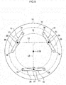
- Figure 3 is an explanation view for explaining an arrangement of three workpiece support units 15 on the table 14. Further, Figure 4 is an enlarged side view of one of the workpiece support units 15.
- each of the workpiece support units 15 provided on the upper surface of the table 14 includes an arm fulcrum 25, an arm 26, two ball fulcrums 27 (ball-shaped fulcrums), and two workpiece seats 28.
- reference character "F1" is a fulcrum position denoting a position (e.g., center position) of each of the arm fulcrums 25.
- the arm fulcrums 25 of the workpiece support units 15 each correspond to the first fulcrum of the present invention.
- Figure 5 the positional relation among arm fulcrums 25 satisfies the requirement that a first line segment L1 connects optional two of the three arm fulcrums 25, a second line segment L2 connects the other first fulcrum and the center of gravity G of the workpiece 11, and the extension of the second line segment L2 perpendicularly intersects with the first line segment L1 at the midpoint of the first line segment L1.
- Figure 5 is an explanation view explaining the positional relation among arm fulcrums 25 in Figure 3 , in a different form of expression.
- each arm fulcrum 25 swingably supports the arm 26, which corresponds to the first arm of the present invention, at a central part in the longitudinal direction of the arm 26 such that the arm 26 is swingable around a horizontal axis.
- each arm fulcrum 25 supports the central part of the arm in the arm's longitudinal direction such that the arm 26 is swingable about a swinging axis (rocking axis) 25a which is parallel to a third line segment L3 that connects each arm fulcrum 25 and the center of gravity G.
- Two ball fulcrums 27 are provided on both end portions in the arm's longitudinal direction on the upper surface of each of the three arms 26 such that the two ball fulcrums 27 are equally distributed in left and right positions across the arm fulcrum 25 (centering on the arm fulcrum 25).
- Each ball fulcrum 27 has a spherical shape and supports the workpiece seat 28 swingably in any direction. This makes it possible for the workpiece seats 28 to be inclined in any direction with respect to each ball fulcrum 27 (the upper surface of the arm 26).
- the workpiece seats 28 correspond to the first contacting parts of the present invention and come into contact with a bottom surface of the workpiece 11. Note that, each of the workpiece seat 28 is sufficiently smaller than the bottom surface of the workpiece 11 and therefore comes into contact with the bottom surface of the workpiece 11 in a point contact manner.
- the three arms 26 are each provided with two workpiece seats 28 and therefore the total six workpiece seats 28 come into contact with the bottom surface of the workpiece 11. Because the workpiece seats 28 are respectively swingably mounted on the ball fulcrum 27, the workpiece seats 28 respectively come into contact with the bottom surface of the workpiece 11 such that they are each inclined relative to the arms 26 along the bottom surface of the workpiece 11.
- Figure 6 is an explanation view for explaining an arrangement of workpiece seats 28.
- the diameter size of the concentric circle R2 of the positions is also changed depending on the dimension (diameter) of the workpiece 11.
- the six workpiece seats 28 are arranged at positions on the concentric circle R2 at equal spacing ⁇ 2, and thus it is possible to support the workpiece 11 at six points uniformly (including almost uniformly). Thereby, the weight of the workpiece 11 can be uniformly distributed to the six points.
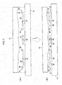
- FIG. 7 are an explanation views for explaining an effect of the workpiece support units 15 of the present embodiment.
- the arms 26 are respectively swingably supported by the arm fulcrums 25, and respectively include the swingable workpiece seats 28.
- the arms 26 can be inclined to either left or right and the workpiece seats 28 can be inclined in an arbitrary direction with respect to the upper surface of the arms 26, depending on an unevenness (convexo-concave) of the bottom surface of the workpiece 11.
- the workpiece seats 28 can be brought into contact with the bottom surface of the workpiece 11 in a state where the workpiece seats 28 surely follow the unevenness of the bottom surface of the workpiece 11.
- the workpiece seats 28 arranged at positions on the concentric circle R2 at equal spacing ⁇ 2, it is possible to uniformly support the workpiece 11 at six points.
- V W ⁇ L 4 / 384 ⁇ E ⁇ I
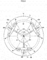
- Figure 8 is an explanation view for explaining the table 14 and the workpiece support unit 15A provided in the roundness measuring device 10 according to a second embodiment.
- the workpiece support units 15 of the above-mentioned first embodiment are specialized in supporting the workpiece 11 having specific dimensions (diameters) and shapes, and thus, it is necessary to exchange the workpiece support units 15 depending on the change of dimension and shape of the workpiece 11. Contrariwise, with the workpiece support units 15A according to the second embodiment, it is possible to support the workpiece 11 having any dimension and shape.
- the roundness measuring device 10 according to the second embodiment is fundamentally the same as that of the above-mentioned first embodiment with the exception that the workpiece support units 15A are provided instead of the workpiece support units 15.
- parts or portions which are functionally or structurally the same as those of the above-mentioned first embodiment are denoted using the same reference numerals, and descriptions thereof are omitted.
- three guide grooves 31 are formed so as to extend from the table center C in a radial direction (radially) on the upper surface of the table 14.
- the arm fulcrums 25 of the workpiece support units 15A are each supported by the guide grooves 31 so as to be slidable. Thereby, the positions of the workpiece support units 15A can be individually adjusted along the guide grooves 31.
- the workpiece support units 15A are fundamentally the same as the workpiece support units 15 of the above-mentioned first embodiment, with the exception that the arm fulcrums 25 are provided and supported slidably along the guide grooves 31 and that the retractable (expandable) arms 26A are provided in the arm's longitudinal direction different from the arms 26 of the first embodiment.
- the positions of the workpiece support units 15A are respectively adjustable along its guide groove 31 and each arm 26A is retractable in the arm's longitudinal direction and therefore it is possible for the position of each workpiece seat 28 to be individually adjusted depending on the dimension (diameter) and shape of the workpiece 11.
- Figure 9 is an explanation view for explaining positional adjustment of each of workpiece seats 28.
- the positions of the arm fulcrums 25 and the lengths of the arms 26A are each adjusted such that the workpiece seats 28 are arranged at positions on the concentric circle (on the same circumference) R2, which corresponds to the diameter of the new workpiece 11, at equal spacing ⁇ 2 (60 degrees).
- R2 the concentric circle
- ⁇ 2 60 degrees
- the workpiece support units 15A according to the second embodiment are able to easily handle and support a workpiece 11A (see Figure 10 ) in which the position of the center of shape of a part to be measured in the roundness measurement is different from the position of the center of gravity G.
- FIG. 10 portions in Figure 10 respectively illustrate a top view and a side view of the workpiece 11A in which the position of the center of shape CS of a part to be measured in the roundness measurement is different from the position of the center of gravity G.
- FIG. 10 in the case where the roundness measuring of a hole 35 formed in the workpiece 11A having a block shape (rectangular parallelepiped shape) is carried out, in the roundness measuring device 10, it is necessary to support the workpiece 11A on the table 14 such that the position of the center of shape CS of the hole 35 and the position of the table center C of the table 14 coincide with one another.
- the workpiece 11A supported by the workpiece support units 15A becomes unstable because the workpiece 11A is not supported based on the position of the center of gravity G as a reference. As a result, it is likely that the inclination, etc., of the workpiece 11A is caused, thereby negatively affecting measurement data of the roundness measurement.
- Figure 11 is an explanation view for explaining the workpiece 11A supported by the workpiece support units 15A.
- the positions of the arm fulcrums 25 and the lengths of the arms 26A are each adjusted such that the workpiece seats 28 are arranged at positions on the concentric circle (on the same circumference) R2, which is based on the position of the center of gravity G of the workpiece 11A as a reference (the circle center), at equal spacing ⁇ 2.
- This makes it possible to carry out the roundness measuring of the hole 35 in a state where the workpiece 11A is uniformly supported by the six workpiece seats 28.
- the guide grooves 31 have a shape radially extending from the table center C.
- the guide grooves 31 are not particularly limited to that shape insofar as the positions of the workpiece support units 15A on the upper surface of the table 14 are changeable (variable).
- various guide parts such as guide rails, etc., may be provided to movably support the arm fulcrums 25 of the workpiece support units 15A.
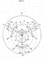
- FIG 12 is an explanation view for explaining workpiece support units 15B provided in the roundness measuring device 10 according to the third embodiment.
- each workpiece support unit 15, 15A is provided with two workpiece seats 28, whereas in the third embodiment each workpiece support unit 15B is provided with three workpiece seats 28.
- the roundness measuring device 10 according to the third embodiment is fundamentally the same as that of the above-mentioned first embodiment with the exception that the workpiece support units 15B are provided instead of the workpiece support units 15.
- parts or portions which are functionally or structurally the same as those of the above-mentioned first embodiment are denoted using the same reference numerals, and descriptions thereof are omitted.
- the workpiece support units 15B are each provided with an arm fulcrum 25, an arm 26B different in shape from the arm 26 of the first embodiment, unillustrated three ball fulcrums 27 (see Figure 4 ), and three workpiece seats 28.
- the arm 26B is fundamentally the same as the arm 26 of the above-mentioned first embodiment with the exception that the arm 26B is formed to have a shape in which the three workpiece seats 28 can be arranged.
- the three workpiece seats 28 are each provided on the upper surfaces of the arms 26B such that the three workpiece seats 28 are arranged on vertexes of an imaginary triangle whose center of gravity GA is located on the arm fulcrums 25, and the three workpiece seats 28 are arranged around the gravity center axis GL (see Figure 1 ) at equal spacing. That is, the three workpiece seats 28 are arranged and distributed in different directions from of the arm fulcrum 25 as a center (reference) on the upper surface of the arm 26B.
- the workpiece 11 is uniformly supported at the nine points and thus it is possible to make the distance between the workpiece fulcrums (workpiece seats 28) shorter than that of the first embodiment.
- the workpiece support units 15B are each provided with the three workpiece seats 28, four or more of the workpiece seats 28 may be provided.
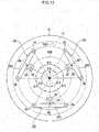
- Figure 13 is an explanation view for explaining workpiece support units 15C provided in a roundness measuring device 10 according to the fourth embodiment.
- all of the nine workpiece seats 28 are arranged at positions on the concentric circle (on the same circumference) R2, whereas in the fourth embodiment, nine workpiece seats 28 are distributed at positions on two concentric circles whose diameters are different from one another.
- the roundness measuring device 10 according to the fourth embodiment is fundamentally the same as that of the above-mentioned first embodiment with the exception that the workpiece support units 15C are provided instead of the workpiece support units 15.
- parts or portions which are functionally or structurally the same as those of the above-mentioned first embodiment are denoted using the same reference numerals, and descriptions thereof are omitted.
- the workpiece support units 15C has a modified arrangement of the workpiece seats 28 of the workpiece support units 15B according to the third embodiment.
- the workpiece support units 15C are each provided with an arm fulcrum 25, an arm 26C, unillustrated three ball fulcrums 27 (see Figure 4 ), and three workpiece seats 28.
- the arm 26C is fundamentally the same as the arm 26B of the above-mentioned third embodiment with the exception that the arm 26C has a shape such that three workpiece seats 28 can be arranged and distributed at positions on two concentric circles whose diameters are different from one another.
- the workpiece seats 28 are distributed at positions on two concentric circles R2A, R2B whose diameters are different from one another, and the workpiece seats 28 are arranged at equal spacings ⁇ 4, ⁇ 5, respectively on the two concentric circles R2A, R2B.
- Such arrangement is particularly effective for supporting a large workpiece 11 which needs a large planar support without causing deflection.
- the workpiece seats 28 are distributed at positions on the two concentric circles R2A, R2B whose diameters are different from one another, and are arranged at equal spacings ⁇ 4, ⁇ 5, respectively on the two concentric circles R2A, R2B.
- the workpiece seats 28 may be distributed at positions on three or more concentric circles whose diameters are different from one another, and are arranged at equal spacings, respectively on the concentric circles.
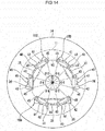
- FIG 14 is an explanation view for explaining workpiece support units 15D provided in a roundness measuring device 10 according to the fifth embodiment.
- each workpiece support unit 15 supports the workpiece 11 at two points
- each workpiece support unit 15D supports the workpiece 11 at four points.
- the roundness measuring device 10 according to the fifth embodiment is fundamentally the same as that of the above-mentioned first embodiment with the exception that the workpiece support units 15D are provided instead of the workpiece support units 15.
- parts or portions which are functionally or structurally the same as those of the above-mentioned first embodiment are denoted using the same reference numerals, and descriptions thereof are omitted.
- the workpiece support units 15D are fundamentally the same as the arms 26 of the first embodiment with the exception that the sub-support units 40 are provided on each end portion in the arm's longitudinal direction of each arm 26.
- the sub-support units 40 correspond to the first contacting parts of the present invention and come into contact with the workpiece 11 at two points.
- the sub-support units 40 are each provided with an arm fulcrum 41, an arm 42, unillustrated two ball fulcrums 27 (see Figure 4 ), and two workpiece seats 45.
- the arm fulcrums 41 correspond to the second fulcrums of the present invention and are each provided on both end portions in the arm's longitudinal direction on the upper surface of each arm 26.
- the arm 42 which corresponds to the second arm of the present invention is supported swingably around a horizontal axis, and is supported at a central part of the arm 42 in the arm's longitudinal direction by each arm fulcrum 41.
- the unillustrated ball fulcrums 27 are provided on both end portions in the arm's longitudinal direction on the upper surface of each arm 42. These ball fulcrums 27 are provided on both end portions in the arm's longitudinal direction on the upper surface in a state where the ball fulcrums 27 are distributed symmetrically (equally) on the left and right sides with the arm fulcrum 41 as a center. Each ball fulcrum 27 supports the workpiece seat 45 swingably in any direction. That is, the workpiece seats 45 are arranged on the upper surface of the arm 42 such that the workpiece seats 45 are distributed from the arm fulcrum 41 in different directions.
- the workpiece seats 45 correspond to the second contacting parts of the present invention and come into contact with a bottom surface of the workpiece 11.
- the workpiece support units 15D are each provided with two sub-support units 40, and arms 42 of the sub-support units 40 are each provided with two swingable workpiece seats 45. Therefore, the total 12 workpiece seats 45 come into contact with the bottom surface of the workpiece 11.
- the workpiece 11 is uniformly supported at the twelve points and thus it is possible to make the distance between the workpiece fulcrums (workpiece seats 28) shorter than that of the first embodiment.
- the workpiece support units 15D are each provided with two sub-support units 40, it is possible for the workpiece seats 45 to follow the unevenness (convexo-concave) of the bottom surface of the workpiece 11 more surely than the first embodiment.
- the workpiece seats 28 (ball fulcrums 27) of the above-mentioned first embodiment are replaced with the sub-support units 40
- the workpiece seats 28 of the embodiments other than the above-mentioned first embodiment may be respectively replaced with the sub-support units 40.
- the sub-support units 40 it is possible to employ the structure similar to the workpiece support units 15B of the third embodiment or to the workpiece support units 15C of the fourth embodiment.
- the workpiece seats 45 of the sub-support units 40 may be respectively replaced with the structure similar to the sub-support units 40. In this case, it is possible to uniformly support the workpiece 11 at twenty-four points.
- the arm fulcrums 25 and the workpiece seats 28, 45 are arranged at positions on concentric circle(s) having the center of gravity G of the workpiece 11 as a circle center, at equal spacing.
- the arm fulcrums 25 and the workpiece seats 28 need not always be arranged at positions on a concentric circle, at equal spacing.
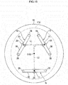
- Figure 15 is an explanation view for explaining another embodiment of the arrangement of the arm fulcrums 25 and the workpiece seats 28.
- three arm fulcrums 25 are arranged on the upper surface of the table 14 such that the center of gravity of the three arm fulcrums 25 (workpiece support units 15) coincides with the center of gravity of the workpiece 11B.
- the arm fulcrums 25 (workpiece support units 15) are arranged such that a first line segment L1 connects two of the three fulcrums, a second line segment L2 connects the other fulcrum and the center of gravity G of the workpiece 11, and the midpoint of the second line segment L2 perpendicularly intersects with the first line segment L1 at the midpoint of the first line segment L1.
- the workpiece 11B is supported by the workpiece seats 28 at six points and therefore it is possible to distribute the load of the workpiece 11B applied to the workpiece seats 28 almost uniformly. Further, it is possible to bring the workpiece seats 28 into contact with the bottom surface of the workpiece 11B in a state where the workpiece seats 28 follow the unevenness (convexo-concave) of the bottom surface the workpiece 11B. As a result, nearly the same effect as each of the embodiments can be obtained.
- the workpiece 11 supporting device of the roundness measuring device 10 has been described by way of example.
- the present invention is applicable to a workpiece 11 supporting device of various shape measuring devices for measuring the shape of the workpiece 11, such as, for example, three-dimensional measuring device, surface shape measuring device, etc.
Landscapes
- Physics & Mathematics (AREA)
- General Physics & Mathematics (AREA)
- A Measuring Device Byusing Mechanical Method (AREA)
- Length Measuring Devices With Unspecified Measuring Means (AREA)
Abstract
Description
- The present invention relates to a workpiece supporting device for supporting a workpiece in a shape measuring device (shape meter).
- Conventionally, as a shape measuring device for measuring a shape of a workpiece (object to be measured), there is known a roundness measuring device for measuring the roundness of a workpiece having a columnar shape or cylindrical shape. In the roundness measuring device, in a state where a probe of a detector is brought into contact with a periphery of the workpiece supported on a table, the detector is rotated relatively around the workpiece and measures the roundness of the workpiece.
- Usually, such a roundness measuring device supports a bottom surface (plane) of the workpiece at three points on the table (see, e.g.,
PTL 1 and PTL 2). Further, in a case where a roundness of a large-sized workpiece is measured, it is known that the roundness is measured in a state where the workpiece is set on the reference plane such as a surface plate (level block). -
- PTL 1: Japanese Patent Application Laid-Open No.
06-341804 - PTL 2: Japanese Patent Application Laid-Open No.
2000-146504 - (A) and (B) portions of
Figure 16 are explanation views for explaining a problem of the conventional technique. Note that, in (A) and (B) portions ofFigure 16 , the unevenness of the bottom surface of theworkpiece 100 is emphasized more than actual size. As shown in (A) portion ofFigure 16 , in the case where theworkpiece 100 is supported at three points by the three support projections 102 (supporting points) provided on the table 101 of the roundness measuring device, if theworkpiece 100 is large, the distance among thesupport projections 102 is widened, and therefore, the deflection of theworkpiece 100 is generated by its own weight (denoted by dotted line in the figure). As a result, the roundness measuring accuracy is degraded. - Further, as shown in (B) portion of
Figure 16 , in order to suppress the generation of deflection due to own weight of theworkpiece 100, if theworkpiece 100 is set on thereference plane 104 such as a surface plate, the flatness of thereference plane 104 affects precision in roundness measurement. Furthermore, theoretically, theworkpiece 100 should make a point contact somewhere with thereference plane 104, but it is not possible to determine where the contact point is. This remains as errors in roundness measurement. Further, thereference plane 104 on which a large-sizedworkpiece 100 can be set becomes large and heavy, and at the same time, it becomes extremely difficult to secure the flatness accuracy of thereference plane 104, thereby increasing costs. - The present invention has been implemented in light of such circumstances, and aims to provide a workpiece supporting device which is able to reduce the deflection of the workpiece at a low cost.
- To achieve the above objective of the present invention, a workpiece supporting device to be provided for a shape measuring device which measures a shape of a workpiece, the workpiece supporting device including: a horizontal table; three first fulcrums provided on an upper surface of the table; first arms swingably supported by the respective first fulcrums, each of the first arms swingably supported at a central part in a longitudinal direction of the first arm by the first fulcrum; and a plurality of first contacting parts swingably provided on an upper surface of the first arm for each first fulcrum and distributed from the first fulcrum in different directions, the first contacting parts configured to come into contact with the workpiece.
- According to the workpiece supporting device, it is possible to shorten the distance between the first contacting parts (workpiece fulcrums) which support the workpiece and is possible to bring the first contacting parts into contact with the bottom surface of the workpiece in a state where the first contacting parts securely follow the bottom surface of the workpiece.
- In the workpiece supporting device according to another aspect of the present invention, positional relation between the first fulcrums satisfies a requirement that a first line segment connects two of the three first fulcrums, a second line segment connects the other one first fulcrum and a center of gravity of the workpiece, and an extension of the second line segment perpendicularly intersects with the first line segment at a midpoint of the first line segment. This makes it possible to stably support the workpiece.
- In the workpiece supporting device according to another aspect of the present invention, the first fulcrums are provided on the upper surface of the table around a gravity center axis, which passes through a center of gravity of the workpiece and extends perpendicularly to the upper surface of the table, at equal spacing. This makes it possible to uniformly support the workpiece by the first contacting parts.
- In the workpiece supporting device according to another aspect of the present invention, the first fulcrums are provided on the upper surface of the table on a concentric circle having a center of gravity of the workpiece as a circle center. This makes it possible to uniformly support the workpiece by the first contacting parts.
- The workpiece supporting device according to another aspect of the present invention further comprises a guide part configured to movably support the first fulcrums along the upper surface of the table. This makes it possible to support the workpiece having any dimension (size) and shape without exchanging the workpiece supporting device.
- In the workpiece supporting device according to another aspect of the present invention, the first fulcrum supports the first arm swingably around an axis which is parallel to a third line segment that connects the first fulcrum and a center of gravity of the workpiece. This makes it possible to bring the first contacting parts into contact with the bottom surface of the workpiece in a state where the first contacting parts securely follow the bottom surface of the workpiece.
- In the workpiece supporting device according to another aspect of the present invention, all of the first contacting parts are arranged on a concentric circle having a center of gravity of the workpiece as a circle center. This makes it possible to uniformly support the workpiece by the first contacting parts.
- In the workpiece supporting device according to another aspect of the present invention, all of the first contacting parts are distributed on a plurality of concentric circles having diameters different from each other. This makes it possible to support a large workpiece.
- In the workpiece supporting device according to another aspect of the present invention, all of the first contacting parts are arranged around a gravity center axis, which passes through a center of gravity of the workpiece and extends perpendicularly to the upper surface of the table, at equal spacing. This makes it possible to uniformly support the workpiece by the first contacting parts.
- In the workpiece supporting device according to another aspect of the present invention, the first arm is retractable in the longitudinal direction of the first arm. This makes it possible to support the workpiece having any dimension (size) and shape without exchanging the workpiece supporting device.
- In the workpiece supporting device according to another aspect of the present invention, the first contacting part includes: second fulcrums provided on the upper surface of the first arm; second arms swingably supported by the second fulcrums, each of the second arms swingably supported at a central part in a longitudinal direction of the second arm by the second fulcrum; and a plurality of second contacting parts swingably provided on an upper surface of the second arm for each second fulcrum and distributed from the second fulcrum in different directions, the second contacting parts configured to come into contact with the workpiece. It is possible to make the distance between the second contacting parts shorter than the distance between the first contacting parts and therefore it is possible to reduce the deflection of the workpiece caused due to own weight of the workpiece.
- The workpiece supporting device of the present invention is able to reduce the deflection of the workpiece at a low cost.
-
-
Figure 1 is a side view illustrating an example of a roundness measuring device. -
Figure 2 is a top view of a table. -
Figure 3 is an explanation view for explaining an arrangement of three workpiece support units on the table. -
Figure 4 is an enlarged side view of one of the workpiece support units. -
Figure 5 is an explanation view explaining positional relation of each arm fulcrum inFigure 3 in a different form of expression. -
Figure 6 is an explanation view for explaining an arrangement of each workpiece seat. -
Figure 7 shows explanation views for explaining an effect of the workpiece support units of the present embodiment, in (A) and (B) portions. -
Figure 8 is an explanation view for explaining the table and the workpiece support unit provided in a roundness measuring device according to a second embodiment. -
Figure 9 is an explanation view for explaining positional adjustment of respective workpiece seats. -
Figure 10 shows, in (A) and (B) portions, a top view and a side view of a workpiece in which a position of the center of shape is different from a position of the center of gravity in a part to be measured in the roundness measurement. -
Figure 11 is an explanation view for explaining the workpiece supported by workpiece support units according to the second embodiment. -
Figure 12 is an explanation view for explaining workpiece support units provided in a roundness measuring device according to a third embodiment. -
Figure 13 is an explanation view for explaining workpiece support units provided in a roundness measuring device according to a fourth embodiment. -
Figure 14 is an explanation view for explaining workpiece support units provided in a roundness measuring device according to a fifth embodiment. -
Figure 15 is an explanation view for explaining another embodiment of the arrangement of the arm fulcrums and the workpiece seats. -
Figure 16 shows explanation views for explaining a problem of the conventional technique, in (A) and (B) portions. -
Figure 1 is a side view illustrating an example of aroundness measuring device 10. As shown inFigure 1 , theroundness measuring device 10 corresponds to a shape measuring device according to the present invention and measures a roundness of a columnar (disc-shaped)workpiece 11. - The
roundness measuring device 10 is provided with a base 12 (pedestal), atable support unit 13, a table 14 (also referred to as a stage), (a) workpiece support unit(s) 15, arotary driving unit 16, a column 17 (also referred to as a strut), a carriage 18 (also referred to as a slider), ahorizontal arm 19, and adetector 20. Note that, theroundness measuring device 10 is not limited to the type shown inFigure 1 and may be various types of known devices. - The
base 12 is a support stand which supports each unit or section of theroundness measuring device 10. Thetable support unit 13 and thecolumn 17 are provided on an upper surface of thebase 12. Further, therotary driving unit 16 is provided inside thebase 12. - The table 14 which has a disc shape is attached on an upper surface of the
table support unit 13. The table 14 is supported by thetable support unit 13 so as to be rotatable around an axis in the Z-axis direction (up and down direction). The table 14 is attached on the upper surface of thetable support unit 13 in a state where inclination of the table 14 is adjusted so as to be horizontal (parallel to the X and Y directions). -
Figure 2 is a top view of the table 14. As shown inFigure 2 , threeworkpiece support units 15 which support theworkpiece 11 are provided on an upper surface of the table 14. In other words, the table 14 supports theworkpiece 11 through each of theworkpiece support units 15. The table 14 and each of theworkpiece support units 15 constitute the workpiece supporting device of the present invention. - The
workpiece 11 whose roundness is to be measured is supported by each of theworkpiece support units 15 so that a center of shape of the workpiece 11 (the center of a shape of a part to be measured) coincides with a table center C which is the center of rotation of the table 14. Note that, since theworkpiece 11 of the present embodiment is columnar (disc-shaped), the position of the center of shape and the position of the center of gravity G of theworkpiece 11 coincide with each other. - Returning to
Figure 1 , therotary driving unit 16 has: a motor; and a drive transmission mechanism which transmits rotation of the motor to the table 14 to rotate the table 14 which is supported on thetable support unit 13, around an axis in the Z-axis direction. Accordingly, theworkpiece 11 also rotates integrally with the table 14 through each of theworkpiece support units 15. As a result, theworkpiece 11 rotates around a rotating axis of the table 14 or around the gravity center axis GL, which extends through the center of gravity G of theworkpiece 11 in a direction perpendicular to the upper surface of the table 14, as a center of rotation (including an approximate center of rotation). - The
column 17 is provided on an upper surface of thebase 12 and on a side end side in the X-axis direction with respect to the table 14. Thecolumn 17 has a shape elongated in the Z-axis direction. Thecarriage 18 is attached to thecolumn 17 so as to be movable in the Z-axis direction. - The
horizontal arm 19 is attached to thecarriage 18 so as to be movable in the X-axis direction (horizontal direction). Thedetector 20 is attached to the tip end of thehorizontal arm 19. - The
detector 20 has aprobe 20a and a displacement detection unit such as an unillustrated differential transformer, etc. Thedetector 20 outputs a detection signal (electrical signal) indicating the displacement of theprobe 20a. - When the roundness measuring of the
workpiece 11 is carried out, thecarriage 18 and thehorizontal arm 19 are driven such that theprobe 20a is brought into contact with a measuring position (outer peripheral surface in the present embodiment) of theworkpiece 11. Next, while theworkpiece 11 is being rotated by therotary driving unit 16 via the table 14, etc., a detection signal is obtained from thedetector 20. The detection signal thus obtained from thedetector 20 is inputted to an unillustrated calculation processing unit. Then, the calculation processing unit carries out the various processing (analyzing) of the detection signal inputted from thedetector 20, and then generates measurement data indicating the roundness of theworkpiece 11. -
Figure 3 is an explanation view for explaining an arrangement of threeworkpiece support units 15 on the table 14. Further,Figure 4 is an enlarged side view of one of theworkpiece support units 15. - As shown in
Figures 3 and4 , each of theworkpiece support units 15 provided on the upper surface of the table 14 includes anarm fulcrum 25, anarm 26, two ball fulcrums 27 (ball-shaped fulcrums), and two workpiece seats 28. Note that, in the Figure, reference character "F1" is a fulcrum position denoting a position (e.g., center position) of each of thearm fulcrums 25. - The
arm fulcrums 25 of theworkpiece support units 15 each correspond to the first fulcrum of the present invention. Thearm fulcrums 25 are provided on the upper surface of the table 14 at positions on the concentric circle (on the same circumference) R1 having the center of gravity G of theworkpiece 11 as a center, and are arranged around the gravity center axis GL passing through the center of gravity G at equal spacing θ1 (θ1 = 120 degrees). Note that, the diameter size of the concentric circle R1 of the positions is changed depending on the dimension (diameter) of theworkpiece 11. - As shown in
Figure 5 , the positional relation amongarm fulcrums 25 satisfies the requirement that a first line segment L1 connects optional two of the threearm fulcrums 25, a second line segment L2 connects the other first fulcrum and the center of gravity G of theworkpiece 11, and the extension of the second line segment L2 perpendicularly intersects with the first line segment L1 at the midpoint of the first line segment L1. Note that,Figure 5 is an explanation view explaining the positional relation amongarm fulcrums 25 inFigure 3 , in a different form of expression. - Returning to
Figures 3 and4 , eacharm fulcrum 25 swingably supports thearm 26, which corresponds to the first arm of the present invention, at a central part in the longitudinal direction of thearm 26 such that thearm 26 is swingable around a horizontal axis. Specifically, eacharm fulcrum 25 supports the central part of the arm in the arm's longitudinal direction such that thearm 26 is swingable about a swinging axis (rocking axis) 25a which is parallel to a third line segment L3 that connects eacharm fulcrum 25 and the center of gravity G. - Two
ball fulcrums 27 are provided on both end portions in the arm's longitudinal direction on the upper surface of each of the threearms 26 such that the twoball fulcrums 27 are equally distributed in left and right positions across the arm fulcrum 25 (centering on the arm fulcrum 25). Each ball fulcrum 27 has a spherical shape and supports theworkpiece seat 28 swingably in any direction. This makes it possible for the workpiece seats 28 to be inclined in any direction with respect to each ball fulcrum 27 (the upper surface of the arm 26). - The workpiece seats 28 correspond to the first contacting parts of the present invention and come into contact with a bottom surface of the
workpiece 11. Note that, each of theworkpiece seat 28 is sufficiently smaller than the bottom surface of theworkpiece 11 and therefore comes into contact with the bottom surface of theworkpiece 11 in a point contact manner. In the present embodiment, the threearms 26 are each provided with twoworkpiece seats 28 and therefore the total sixworkpiece seats 28 come into contact with the bottom surface of theworkpiece 11. Because the workpiece seats 28 are respectively swingably mounted on the ball fulcrum 27, the workpiece seats 28 respectively come into contact with the bottom surface of theworkpiece 11 such that they are each inclined relative to thearms 26 along the bottom surface of theworkpiece 11. -
Figure 6 is an explanation view for explaining an arrangement of workpiece seats 28. As shown inFigure 6 , in the present embodiment, the positions of thearm fulcrums 25, the lengths of thearms 26, and the positions of the workpiece seats 28 on thearms 26 are each adjusted such that the workpiece seats 28 are disposed at positions on the concentric circle (on the same circumference) R2 having the center of gravity G of theworkpiece 11 as a center and are arranged around the gravity center axis GL at equal spacing θ2 (θ2 = 60 degrees). Note that, as with the positions on the concentric circle R1, the diameter size of the concentric circle R2 of the positions is also changed depending on the dimension (diameter) of theworkpiece 11. - In this way, in the present embodiment, the six
workpiece seats 28 are arranged at positions on the concentric circle R2 at equal spacing θ2, and thus it is possible to support theworkpiece 11 at six points uniformly (including almost uniformly). Thereby, the weight of theworkpiece 11 can be uniformly distributed to the six points. - (A) and (B) portions in
Figure 7 are an explanation views for explaining an effect of theworkpiece support units 15 of the present embodiment. As shown in (A) portion and (B) portion inFigure 7 , in the present embodiment, thearms 26 are respectively swingably supported by thearm fulcrums 25, and respectively include the swingable workpiece seats 28. Thus, in a case where theworkpiece 11 is set on theworkpiece support units 15, thearms 26 can be inclined to either left or right and the workpiece seats 28 can be inclined in an arbitrary direction with respect to the upper surface of thearms 26, depending on an unevenness (convexo-concave) of the bottom surface of theworkpiece 11. Therefore, the workpiece seats 28 can be brought into contact with the bottom surface of theworkpiece 11 in a state where the workpiece seats 28 surely follow the unevenness of the bottom surface of theworkpiece 11. As a result, with the use of all of the sixworkpiece seats 28 arranged at positions on the concentric circle R2 at equal spacing θ2, it is possible to uniformly support theworkpiece 11 at six points. - In this way, in the case where the
workpiece 11 is uniformly supported by the sixworkpiece seats 28, as compared to the case of the three-point support like the above-mentioned comparative example shown in (A) portion inFigure 16 , the distance between the workpiece supporting points (workpiece seats 28) can be shortened. Therefore, it is possible to minimize the generation of deflection of theworkpiece 11 due to its own weight. - Specifically, the maximum deflection amount V of the
workpiece 11 may be represented by Equation (1):
- where W is the own weight of the
workpiece 11, - L is the distance between the workpiece fulcrums,
- E is a Young's modulus of the
workpiece 11, and - I is a section modulus (modulus of section) of the
workpiece 11. - Here, in a case where, for example, the distance between the workpiece fulcrums is shortened by half (L' = 2L), even if the own weight of the
workpiece 11 is doubled (W' = 2W) due to the upsizing of theworkpiece 11, the maximum deflection amount V' of theworkpiece 11 may be represented by Equation (2):
- As shown in the above Equation (2), by shortening the distance between the workpiece fulcrums (workpiece seats 28), it is possible to support even a
large workpiece 11 in a state where the deflection of theworkpiece 11 due to its own weight is reduced. Further, because theworkpiece support units 15 do not require a high precision machining, it is possible to manufacture them at lower cost. Furthermore, theworkpiece support units 15 are tools (jigs) only used at positions where theworkpiece 11 is to be supported, and therefore it is possible to manufacture theworkpiece support units 15 with a smaller size and lighter weight at lower cost. Thus, as compared to the case where thelarge reference plane 104 is formed as shown in the above-mentioned (B) portion inFigure 16 , it is possible to manufacture theroundness measuring device 10 at lower cost. As a result, with theworkpiece support units 15 of the present invention, it is possible to reduce the deflection of theworkpiece 11 at lower cost. - Further, differently from the case in which the
workpiece 11 is set on thelarge reference plane 104 as shown in the above-mentioned (B) portion inFigure 16 , it is possible to specify the positions of workpiece supporting points which support theworkpiece 11. Thus, even if a very small deflection is generated in theworkpiece 11, it is possible to correct roundness measuring data by the use of the theoretical deformation calculation of theworkpiece 11. Thus, it is possible to reduce error in roundness measurement. -
Figure 8 is an explanation view for explaining the table 14 and theworkpiece support unit 15A provided in theroundness measuring device 10 according to a second embodiment. Theworkpiece support units 15 of the above-mentioned first embodiment are specialized in supporting theworkpiece 11 having specific dimensions (diameters) and shapes, and thus, it is necessary to exchange theworkpiece support units 15 depending on the change of dimension and shape of theworkpiece 11. Contrariwise, with theworkpiece support units 15A according to the second embodiment, it is possible to support theworkpiece 11 having any dimension and shape. - Note that, the
roundness measuring device 10 according to the second embodiment is fundamentally the same as that of the above-mentioned first embodiment with the exception that theworkpiece support units 15A are provided instead of theworkpiece support units 15. As such, parts or portions which are functionally or structurally the same as those of the above-mentioned first embodiment are denoted using the same reference numerals, and descriptions thereof are omitted. - As shown in
Figure 8 , on the upper surface of the table 14 according to the second embodiment, three guide grooves 31 (corresponding to the guide part of the present invention) are formed so as to extend from the table center C in a radial direction (radially) on the upper surface of the table 14. Theguide grooves 31 are formed on the upper surface of the table 14 and arranged around an axis which passes through the table center C and is perpendicular to the upper surface of the table 14, at equal spacing (θ1 = 120 degrees). In addition, thearm fulcrums 25 of theworkpiece support units 15A are each supported by theguide grooves 31 so as to be slidable. Thereby, the positions of theworkpiece support units 15A can be individually adjusted along theguide grooves 31. - The
workpiece support units 15A are fundamentally the same as theworkpiece support units 15 of the above-mentioned first embodiment, with the exception that thearm fulcrums 25 are provided and supported slidably along theguide grooves 31 and that the retractable (expandable)arms 26A are provided in the arm's longitudinal direction different from thearms 26 of the first embodiment. - In this way, in the second embodiment, the positions of the
workpiece support units 15A are respectively adjustable along itsguide groove 31 and eacharm 26A is retractable in the arm's longitudinal direction and therefore it is possible for the position of eachworkpiece seat 28 to be individually adjusted depending on the dimension (diameter) and shape of theworkpiece 11. -
Figure 9 is an explanation view for explaining positional adjustment of each of workpiece seats 28. As shown inFigure 9 , in the case where the roundness measuring of anew workpiece 11 having a different diameter is carried out, the positions of thearm fulcrums 25 and the lengths of thearms 26A are each adjusted such that the workpiece seats 28 are arranged at positions on the concentric circle (on the same circumference) R2, which corresponds to the diameter of thenew workpiece 11, at equal spacing θ2 (60 degrees). This makes it possible for even anew workpiece 11 having a different diameter to be uniformly supported by the sixworkpiece seats 28 similarly to the above-mentioned embodiments. - Further, the
workpiece support units 15A according to the second embodiment are able to easily handle and support aworkpiece 11A (seeFigure 10 ) in which the position of the center of shape of a part to be measured in the roundness measurement is different from the position of the center of gravity G. - (A) and (B) portions in
Figure 10 respectively illustrate a top view and a side view of theworkpiece 11A in which the position of the center of shape CS of a part to be measured in the roundness measurement is different from the position of the center of gravity G. As shown in (A) and (B) portions ofFigure 10 , in the case where the roundness measuring of ahole 35 formed in theworkpiece 11A having a block shape (rectangular parallelepiped shape) is carried out, in theroundness measuring device 10, it is necessary to support theworkpiece 11A on the table 14 such that the position of the center of shape CS of thehole 35 and the position of the table center C of the table 14 coincide with one another. - Then, if the
workpiece 11A is supported by theworkpiece support units 15A based on the center of shape CS as a reference, theworkpiece 11A supported by theworkpiece support units 15A becomes unstable because theworkpiece 11A is not supported based on the position of the center of gravity G as a reference. As a result, it is likely that the inclination, etc., of theworkpiece 11A is caused, thereby negatively affecting measurement data of the roundness measurement. -
Figure 11 is an explanation view for explaining theworkpiece 11A supported by theworkpiece support units 15A. As shown inFigure 11 , in the case where the roundness measuring of thehole 35 of theworkpiece 11A is carried out, in a state in which the center of shape CS of thehole 35 coincides with the table center C, the positions of thearm fulcrums 25 and the lengths of thearms 26A are each adjusted such that the workpiece seats 28 are arranged at positions on the concentric circle (on the same circumference) R2, which is based on the position of the center of gravity G of theworkpiece 11A as a reference (the circle center), at equal spacing θ2. This makes it possible to carry out the roundness measuring of thehole 35 in a state where theworkpiece 11A is uniformly supported by the six workpiece seats 28. - Note that, in the second embodiment, the
guide grooves 31 have a shape radially extending from the table center C. However, theguide grooves 31 are not particularly limited to that shape insofar as the positions of theworkpiece support units 15A on the upper surface of the table 14 are changeable (variable). Further, instead of forming theguide grooves 31 in the table 14, various guide parts such as guide rails, etc., may be provided to movably support thearm fulcrums 25 of theworkpiece support units 15A. -
Figure 12 is an explanation view for explainingworkpiece support units 15B provided in theroundness measuring device 10 according to the third embodiment. In the above-mentioned embodiments, eachworkpiece support unit workpiece seats 28, whereas in the third embodiment eachworkpiece support unit 15B is provided with three workpiece seats 28. - Note that, the
roundness measuring device 10 according to the third embodiment is fundamentally the same as that of the above-mentioned first embodiment with the exception that theworkpiece support units 15B are provided instead of theworkpiece support units 15. As such, parts or portions which are functionally or structurally the same as those of the above-mentioned first embodiment are denoted using the same reference numerals, and descriptions thereof are omitted. - As shown in
Figure 12 , theworkpiece support units 15B are each provided with anarm fulcrum 25, anarm 26B different in shape from thearm 26 of the first embodiment, unillustrated three ball fulcrums 27 (seeFigure 4 ), and three workpiece seats 28. - The
arm 26B is fundamentally the same as thearm 26 of the above-mentioned first embodiment with the exception that thearm 26B is formed to have a shape in which the threeworkpiece seats 28 can be arranged. - The three workpiece seats 28 (ball fulcrums 27) are each provided on the upper surfaces of the
arms 26B such that the threeworkpiece seats 28 are arranged on vertexes of an imaginary triangle whose center of gravity GA is located on thearm fulcrums 25, and the threeworkpiece seats 28 are arranged around the gravity center axis GL (seeFigure 1 ) at equal spacing. That is, the threeworkpiece seats 28 are arranged and distributed in different directions from of thearm fulcrum 25 as a center (reference) on the upper surface of thearm 26B. More specifically, the total nineworkpiece seats 28 provided on theworkpiece support units 15B are arranged at positions on the concentric circle (on the same circumference) R2 having the center of gravity G of theworkpiece 11 as a circle center and are arranged around the gravity center axis GL at equal spacing θ3 (θ3 = 40 degrees). This makes it possible to uniformly support theworkpiece 11 at nine points. - In this way, in the third embodiment, the
workpiece 11 is uniformly supported at the nine points and thus it is possible to make the distance between the workpiece fulcrums (workpiece seats 28) shorter than that of the first embodiment. Thus, it is possible to reduce the deflection of theworkpiece 11 caused due to its own weight more than the first embodiment. - Note that, in the third embodiment, although the
workpiece support units 15B are each provided with the threeworkpiece seats 28, four or more of the workpiece seats 28 may be provided. -
Figure 13 is an explanation view for explaining workpiece support units 15C provided in aroundness measuring device 10 according to the fourth embodiment. In the third embodiment, all of the nineworkpiece seats 28 are arranged at positions on the concentric circle (on the same circumference) R2, whereas in the fourth embodiment, nineworkpiece seats 28 are distributed at positions on two concentric circles whose diameters are different from one another. - Note that, the
roundness measuring device 10 according to the fourth embodiment is fundamentally the same as that of the above-mentioned first embodiment with the exception that the workpiece support units 15C are provided instead of theworkpiece support units 15. As such, parts or portions which are functionally or structurally the same as those of the above-mentioned first embodiment are denoted using the same reference numerals, and descriptions thereof are omitted. - As shown in
Figure 13 , the workpiece support units 15C has a modified arrangement of the workpiece seats 28 of theworkpiece support units 15B according to the third embodiment. The workpiece support units 15C are each provided with anarm fulcrum 25, anarm 26C, unillustrated three ball fulcrums 27 (seeFigure 4 ), and three workpiece seats 28. - The
arm 26C is fundamentally the same as thearm 26B of the above-mentioned third embodiment with the exception that thearm 26C has a shape such that threeworkpiece seats 28 can be arranged and distributed at positions on two concentric circles whose diameters are different from one another. - Regarding six
workpiece seats 28 of the nineworkpiece seats 28, the threearms 26C are each provided with two workpiece seats such that the six workpiece seats are arranged at positions on a larger diameter side concentric circle R2A having the center of gravity G as a circle center and are arranged around the gravity center axis GL at equal spacing θ4 (θ4 = 60 degrees). Regarding the remaining threeworkpiece seats 28, the threearms 26 are each provided with one workpiece seat such that the three workpiece seats are arranged at positions on a smaller diameter side concentric circle R2B having the center of gravity G as a circle center and are arranged around the gravity center axis GL at equal spacing θ5 (θ5 = 120 degrees). This makes it possible to uniformly support the outer peripheral portions of the bottom surface of theworkpiece 11 at six points and to uniformly support the inner peripheral portions of the bottom surface of theworkpiece 11 at three points. Namely, it is possible to uniformly support theworkpiece 11 at nine points. - In this way, in the fourth embodiment, the workpiece seats 28 are distributed at positions on two concentric circles R2A, R2B whose diameters are different from one another, and the workpiece seats 28 are arranged at equal spacings θ4, θ5, respectively on the two concentric circles R2A, R2B. Such arrangement is particularly effective for supporting a
large workpiece 11 which needs a large planar support without causing deflection. - Note that, in the fourth embodiment, the workpiece seats 28 are distributed at positions on the two concentric circles R2A, R2B whose diameters are different from one another, and are arranged at equal spacings θ4, θ5, respectively on the two concentric circles R2A, R2B. However, the workpiece seats 28 may be distributed at positions on three or more concentric circles whose diameters are different from one another, and are arranged at equal spacings, respectively on the concentric circles.
-
Figure 14 is an explanation view for explainingworkpiece support units 15D provided in aroundness measuring device 10 according to the fifth embodiment. In the above-mentioned first embodiment, eachworkpiece support unit 15 supports theworkpiece 11 at two points, whereas in the fifth embodiment eachworkpiece support unit 15D supports theworkpiece 11 at four points. - Note that, the
roundness measuring device 10 according to the fifth embodiment is fundamentally the same as that of the above-mentioned first embodiment with the exception that theworkpiece support units 15D are provided instead of theworkpiece support units 15. As such, parts or portions which are functionally or structurally the same as those of the above-mentioned first embodiment are denoted using the same reference numerals, and descriptions thereof are omitted. - The
workpiece support units 15D are fundamentally the same as thearms 26 of the first embodiment with the exception that thesub-support units 40 are provided on each end portion in the arm's longitudinal direction of eacharm 26. - The
sub-support units 40 correspond to the first contacting parts of the present invention and come into contact with theworkpiece 11 at two points. Thesub-support units 40 are each provided with anarm fulcrum 41, anarm 42, unillustrated two ball fulcrums 27 (seeFigure 4 ), and two workpiece seats 45. - The
arm fulcrums 41 correspond to the second fulcrums of the present invention and are each provided on both end portions in the arm's longitudinal direction on the upper surface of eacharm 26. Thearm 42 which corresponds to the second arm of the present invention is supported swingably around a horizontal axis, and is supported at a central part of thearm 42 in the arm's longitudinal direction by eacharm fulcrum 41. - The unillustrated ball fulcrums 27 (see
Figure 4 ) are provided on both end portions in the arm's longitudinal direction on the upper surface of eacharm 42. Theseball fulcrums 27 are provided on both end portions in the arm's longitudinal direction on the upper surface in a state where theball fulcrums 27 are distributed symmetrically (equally) on the left and right sides with thearm fulcrum 41 as a center. Each ball fulcrum 27 supports theworkpiece seat 45 swingably in any direction. That is, the workpiece seats 45 are arranged on the upper surface of thearm 42 such that the workpiece seats 45 are distributed from thearm fulcrum 41 in different directions. - The workpiece seats 45 correspond to the second contacting parts of the present invention and come into contact with a bottom surface of the
workpiece 11. In the fifth embodiment, theworkpiece support units 15D are each provided with twosub-support units 40, andarms 42 of thesub-support units 40 are each provided with two swingable workpiece seats 45. Therefore, the total 12workpiece seats 45 come into contact with the bottom surface of theworkpiece 11. - Then, in the fifth embodiment, the positions of the
arm fulcrums 25, the lengths of thearms 26, the positions and directions of thearm fulcrums 41, the lengths of thearms 42, and the positions of the workpiece seats 45 on thearms 42, etc., are each adjusted such that the workpiece seats 45 are arranged at positions on the concentric circle (on the same circumference) R2 having the center of gravity G as a circle center, and are arranged around the gravity center axis GL at equal spacing θ6 (θ6 = 30 degrees). This makes it possible to uniformly support theworkpiece 11 at twelve points. - In this way, in the fifth embodiment, the
workpiece 11 is uniformly supported at the twelve points and thus it is possible to make the distance between the workpiece fulcrums (workpiece seats 28) shorter than that of the first embodiment. Thus, it is possible to reduce the deflection of theworkpiece 11 caused due to own weight of theworkpiece 11 more effectively than the first embodiment. Further, because theworkpiece support units 15D are each provided with twosub-support units 40, it is possible for the workpiece seats 45 to follow the unevenness (convexo-concave) of the bottom surface of theworkpiece 11 more surely than the first embodiment. - Note that, in the fifth embodiment, a configuration in which the workpiece seats 28 (ball fulcrums 27) of the above-mentioned first embodiment are replaced with the
sub-support units 40 has been described as an example. The workpiece seats 28 of the embodiments other than the above-mentioned first embodiment may be respectively replaced with thesub-support units 40. Further, as thesub-support units 40, it is possible to employ the structure similar to theworkpiece support units 15B of the third embodiment or to the workpiece support units 15C of the fourth embodiment. - Further, in the fifth embodiment, the workpiece seats 45 of the
sub-support units 40 may be respectively replaced with the structure similar to thesub-support units 40. In this case, it is possible to uniformly support theworkpiece 11 at twenty-four points. - In the above-mentioned embodiments, the
arm fulcrums 25 and the workpiece seats 28, 45 are arranged at positions on concentric circle(s) having the center of gravity G of theworkpiece 11 as a circle center, at equal spacing. However, as inFigure 15 explained below, thearm fulcrums 25 and the workpiece seats 28 need not always be arranged at positions on a concentric circle, at equal spacing. -
Figure 15 is an explanation view for explaining another embodiment of the arrangement of thearm fulcrums 25 and the workpiece seats 28. As shown inFigure 15 , in other embodiments, threearm fulcrums 25 are arranged on the upper surface of the table 14 such that the center of gravity of the three arm fulcrums 25 (workpiece support units 15) coincides with the center of gravity of theworkpiece 11B. That is, the arm fulcrums 25 (workpiece support units 15) are arranged such that a first line segment L1 connects two of the three fulcrums, a second line segment L2 connects the other fulcrum and the center of gravity G of theworkpiece 11, and the midpoint of the second line segment L2 perpendicularly intersects with the first line segment L1 at the midpoint of the first line segment L1. - Also in this case, the
workpiece 11B is supported by the workpiece seats 28 at six points and therefore it is possible to distribute the load of theworkpiece 11B applied to the workpiece seats 28 almost uniformly. Further, it is possible to bring the workpiece seats 28 into contact with the bottom surface of theworkpiece 11B in a state where the workpiece seats 28 follow the unevenness (convexo-concave) of the bottom surface theworkpiece 11B. As a result, nearly the same effect as each of the embodiments can be obtained. - In each of the embodiments, the
workpiece 11 supporting device of theroundness measuring device 10 has been described by way of example. However, the present invention is applicable to aworkpiece 11 supporting device of various shape measuring devices for measuring the shape of theworkpiece 11, such as, for example, three-dimensional measuring device, surface shape measuring device, etc. -
- 10
- roundness measuring device
- 11, 11A, 11B
- workpiece
- 14
- table
- 15, 15A-15D
- workpiece support unit
- 25
- arm fulcrum
- 26, 26A-26C
- arm
- 28
- workpiece seat
- 31
- guide groove
- 40
- sub-support unit
- 45
- workpiece seat
Claims (11)
- A workpiece supporting device to be provided for a shape measuring device which measures a shape of a workpiece, the workpiece supporting device comprising:a horizontal table;three first fulcrums provided on an upper surface of the table;first arms swingably supported by the respective first fulcrums, each of the first arms swingably supported at a central part in a longitudinal direction of the first arm by the first fulcrum; anda plurality of first contacting parts swingably provided on an upper surface of the first arm for each first fulcrum and distributed from the first fulcrum in different directions, the first contacting parts configured to come into contact with the workpiece.
- The workpiece supporting device according to claim 1, wherein positional relation between the first fulcrums satisfies a requirement that a first line segment connects two of the three first fulcrums, a second line segment connects the other one first fulcrum and a center of gravity of the workpiece, and an extension of the second line segment perpendicularly intersects with the first line segment at a midpoint of the first line segment.
- The workpiece supporting device according to claim 1 or 2, wherein the first fulcrums are provided on the upper surface of the table around a gravity center axis, which passes through a center of gravity of the workpiece and extends perpendicularly to the upper surface of the table, at equal spacing.
- The workpiece supporting device according to any one of claims 1 to 3, wherein the first fulcrums are provided on the upper surface of the table on a concentric circle having a center of gravity of the workpiece as a circle center.
- The workpiece supporting device according to any one of claims 1 to 4, comprising a guide part configured to movably support the first fulcrums along the upper surface of the table.
- The workpiece supporting device according to any one of claims 1 to 5, wherein the first fulcrum supports the first arm swingably around an axis which is parallel to a third line segment that connects the first fulcrum and a center of gravity of the workpiece.
- The workpiece supporting device according to any one of claims 1 to 6, wherein all of the first contacting parts are arranged on a concentric circle having a center of gravity of the workpiece as a circle center.
- The workpiece supporting device according to claim 7, wherein all of the first contacting parts are distributed on a plurality of concentric circles having diameters different from each other.
- The workpiece supporting device according to any one of claims 1 to 8, wherein all of the first contacting parts are arranged around a gravity center axis, which passes through a center of gravity of the workpiece and extends perpendicularly to the upper surface of the table, at equal spacing.
- The workpiece supporting device according to any one of claims 1 to 9, wherein the first arm is retractable in the longitudinal direction of the first arm.
- The workpiece supporting device according to any one of claims 1 to 10, wherein the first contacting part comprises:second fulcrums provided on the upper surface of the first arm;second arms swingably supported by the second fulcrums, each of the second arms swingably supported at a central part in a longitudinal direction of the second arm by the second fulcrum; anda plurality of second contacting parts swingably provided on an upper surface of the second arm for each second fulcrum and distributed from the second fulcrum in different directions, the second contacting parts configured to come into contact with the workpiece.
Applications Claiming Priority (2)
| Application Number | Priority Date | Filing Date | Title |
|---|---|---|---|
| JP2016076292A JP6171260B1 (en) | 2016-04-06 | 2016-04-06 | Work support device |
| PCT/JP2017/013315 WO2017175662A1 (en) | 2016-04-06 | 2017-03-30 | Workpiece supporting device |
Publications (3)
| Publication Number | Publication Date |
|---|---|
| EP3441716A1 true EP3441716A1 (en) | 2019-02-13 |
| EP3441716A4 EP3441716A4 (en) | 2019-02-20 |
| EP3441716B1 EP3441716B1 (en) | 2020-03-04 |
Family
ID=59505110
Family Applications (1)
| Application Number | Title | Priority Date | Filing Date |
|---|---|---|---|
| EP17779041.7A Active EP3441716B1 (en) | 2016-04-06 | 2017-03-30 | Workpiece supporting device |
Country Status (3)
| Country | Link |
|---|---|
| EP (1) | EP3441716B1 (en) |
| JP (1) | JP6171260B1 (en) |
| WO (1) | WO2017175662A1 (en) |
Families Citing this family (3)
| Publication number | Priority date | Publication date | Assignee | Title |
|---|---|---|---|---|
| CN111644858A (en) * | 2020-06-28 | 2020-09-11 | 泰州天融科技有限公司 | Numerical control machine tool base easy to control |
| CN114705102B (en) * | 2022-04-21 | 2024-02-13 | 长江师范学院 | A fastening detection device for steel structure engineering |
| CN117073519B (en) * | 2023-10-12 | 2023-12-22 | 联峰钢铁(张家港)有限公司 | Online detection system for continuous casting round billet |
Family Cites Families (4)
| Publication number | Priority date | Publication date | Assignee | Title |
|---|---|---|---|---|
| JP4106527B2 (en) * | 2002-02-21 | 2008-06-25 | トヨタ自動車株式会社 | Heat treatment jig |
| JP4251546B2 (en) * | 2003-09-12 | 2009-04-08 | 黒田精工株式会社 | Thin plate horizontal holding device |
| US9031813B2 (en) * | 2010-08-27 | 2015-05-12 | Corning Incorporated | Methods and apparatus for estimating gravity-free shapes |
| JP5752165B2 (en) * | 2013-03-19 | 2015-07-22 | キヤノン株式会社 | Support device and measuring device |
-
2016
- 2016-04-06 JP JP2016076292A patent/JP6171260B1/en active Active
-
2017
- 2017-03-30 EP EP17779041.7A patent/EP3441716B1/en active Active
- 2017-03-30 WO PCT/JP2017/013315 patent/WO2017175662A1/en not_active Ceased
Also Published As
| Publication number | Publication date |
|---|---|
| EP3441716B1 (en) | 2020-03-04 |
| WO2017175662A1 (en) | 2017-10-12 |
| JP6171260B1 (en) | 2017-08-02 |
| JP2017187382A (en) | 2017-10-12 |
| EP3441716A4 (en) | 2019-02-20 |
Similar Documents
| Publication | Publication Date | Title |
|---|---|---|
| CN104272061B (en) | Method for determining the axis of a turntable of a coordinate measuring device | |
| CN101852583B (en) | Circularity detection device | |
| CN103075991B (en) | The measurement mechanism of super-huge gear and measuring method thereof | |
| EP3441716B1 (en) | Workpiece supporting device | |
| JP2017187470A (en) | Surface shape measuring device | |
| CN101221031A (en) | New high-precision spherical multi-parameter measuring instrument and its precision adjustment method | |
| JP6657552B2 (en) | Flatness measurement method | |
| JP3564106B2 (en) | Perfect circle measuring method and perfect circle measuring device | |
| JP5705188B2 (en) | Roundness measuring device | |
| JP7324900B2 (en) | Inside diameter measuring device | |
| CN108020193A (en) | A kind of more gauge head postures of swing arm contour detecting are from correction system and antidote | |
| CN108267061A (en) | A kind of method that elevation carrection is determined on JD25-C horizontal metroscopes | |
| JP2019045312A (en) | Stylus and surface shape measurement device | |
| JP5489017B2 (en) | Method of calculating the amount of misalignment in a roundness measuring device | |
| CN101900537B (en) | Detection method and device of three-dimensional sphericity error of global spherical surface of optical sphere part | |
| JP4644190B2 (en) | Curvature radius measuring device | |
| JP6213800B1 (en) | Work support device | |
| JP2008008879A (en) | Measuring instrument, measuring reference, and precision machine tool | |
| JP2009145152A (en) | Measuring device | |
| JP4890188B2 (en) | Motion error measurement reference body and motion error measurement device | |
| CN106289027B (en) | Roundness measuring device and roundness measuring method | |
| JP2018025563A (en) | Workpiece support device | |
| JP2019174263A (en) | Inner diameter measuring apparatus and method for measurement using the same | |
| JP2015083986A (en) | Circularity measuring device | |
| CN204404992U (en) | High-precision flat face measuring apparatus |
Legal Events
| Date | Code | Title | Description |
|---|---|---|---|
| STAA | Information on the status of an ep patent application or granted ep patent |
Free format text: STATUS: THE INTERNATIONAL PUBLICATION HAS BEEN MADE |
|
| PUAI | Public reference made under article 153(3) epc to a published international application that has entered the european phase |
Free format text: ORIGINAL CODE: 0009012 |
|
| STAA | Information on the status of an ep patent application or granted ep patent |
Free format text: STATUS: REQUEST FOR EXAMINATION WAS MADE |
|
| 17P | Request for examination filed |
Effective date: 20181105 |
|
| AK | Designated contracting states |
Kind code of ref document: A1 Designated state(s): AL AT BE BG CH CY CZ DE DK EE ES FI FR GB GR HR HU IE IS IT LI LT LU LV MC MK MT NL NO PL PT RO RS SE SI SK SM TR |
|
| AX | Request for extension of the european patent |
Extension state: BA ME |
|
| A4 | Supplementary search report drawn up and despatched |
Effective date: 20190123 |
|
| RIC1 | Information provided on ipc code assigned before grant |
Ipc: G01B 5/00 20060101ALI20190117BHEP Ipc: G01B 21/00 20060101AFI20190117BHEP |
|
| DAV | Request for validation of the european patent (deleted) | ||
| DAX | Request for extension of the european patent (deleted) | ||
| REG | Reference to a national code |
Ref country code: DE Ref legal event code: R079 Ref document number: 602017012704 Country of ref document: DE Free format text: PREVIOUS MAIN CLASS: G01B0021000000 Ipc: G01B0007280000 |
|
| GRAP | Despatch of communication of intention to grant a patent |
Free format text: ORIGINAL CODE: EPIDOSNIGR1 |
|
| STAA | Information on the status of an ep patent application or granted ep patent |
Free format text: STATUS: GRANT OF PATENT IS INTENDED |
|
| RIC1 | Information provided on ipc code assigned before grant |
Ipc: G01B 5/00 20060101ALI20190920BHEP Ipc: G01B 7/28 20060101AFI20190920BHEP |
|
| INTG | Intention to grant announced |
Effective date: 20191011 |
|
| GRAS | Grant fee paid |
Free format text: ORIGINAL CODE: EPIDOSNIGR3 |
|
| GRAA | (expected) grant |
Free format text: ORIGINAL CODE: 0009210 |
|
| STAA | Information on the status of an ep patent application or granted ep patent |
Free format text: STATUS: THE PATENT HAS BEEN GRANTED |
|
| AK | Designated contracting states |
Kind code of ref document: B1 Designated state(s): AL AT BE BG CH CY CZ DE DK EE ES FI FR GB GR HR HU IE IS IT LI LT LU LV MC MK MT NL NO PL PT RO RS SE SI SK SM TR |
|
| REG | Reference to a national code |
Ref country code: GB Ref legal event code: FG4D |
|
| REG | Reference to a national code |
Ref country code: CH Ref legal event code: EP |
|
| REG | Reference to a national code |
Ref country code: AT Ref legal event code: REF Ref document number: 1240879 Country of ref document: AT Kind code of ref document: T Effective date: 20200315 |
|
| REG | Reference to a national code |
Ref country code: DE Ref legal event code: R096 Ref document number: 602017012704 Country of ref document: DE |
|
| REG | Reference to a national code |
Ref country code: IE Ref legal event code: FG4D |
|
| PG25 | Lapsed in a contracting state [announced via postgrant information from national office to epo] |
Ref country code: FI Free format text: LAPSE BECAUSE OF FAILURE TO SUBMIT A TRANSLATION OF THE DESCRIPTION OR TO PAY THE FEE WITHIN THE PRESCRIBED TIME-LIMIT Effective date: 20200304 Ref country code: RS Free format text: LAPSE BECAUSE OF FAILURE TO SUBMIT A TRANSLATION OF THE DESCRIPTION OR TO PAY THE FEE WITHIN THE PRESCRIBED TIME-LIMIT Effective date: 20200304 Ref country code: NO Free format text: LAPSE BECAUSE OF FAILURE TO SUBMIT A TRANSLATION OF THE DESCRIPTION OR TO PAY THE FEE WITHIN THE PRESCRIBED TIME-LIMIT Effective date: 20200604 |
|
| REG | Reference to a national code |
Ref country code: NL Ref legal event code: MP Effective date: 20200304 |
|
| PG25 | Lapsed in a contracting state [announced via postgrant information from national office to epo] |
Ref country code: HR Free format text: LAPSE BECAUSE OF FAILURE TO SUBMIT A TRANSLATION OF THE DESCRIPTION OR TO PAY THE FEE WITHIN THE PRESCRIBED TIME-LIMIT Effective date: 20200304 Ref country code: BG Free format text: LAPSE BECAUSE OF FAILURE TO SUBMIT A TRANSLATION OF THE DESCRIPTION OR TO PAY THE FEE WITHIN THE PRESCRIBED TIME-LIMIT Effective date: 20200604 Ref country code: GR Free format text: LAPSE BECAUSE OF FAILURE TO SUBMIT A TRANSLATION OF THE DESCRIPTION OR TO PAY THE FEE WITHIN THE PRESCRIBED TIME-LIMIT Effective date: 20200605 Ref country code: LV Free format text: LAPSE BECAUSE OF FAILURE TO SUBMIT A TRANSLATION OF THE DESCRIPTION OR TO PAY THE FEE WITHIN THE PRESCRIBED TIME-LIMIT Effective date: 20200304 Ref country code: SE Free format text: LAPSE BECAUSE OF FAILURE TO SUBMIT A TRANSLATION OF THE DESCRIPTION OR TO PAY THE FEE WITHIN THE PRESCRIBED TIME-LIMIT Effective date: 20200304 |
|
| REG | Reference to a national code |
Ref country code: LT Ref legal event code: MG4D |
|
| PG25 | Lapsed in a contracting state [announced via postgrant information from national office to epo] |
Ref country code: NL Free format text: LAPSE BECAUSE OF FAILURE TO SUBMIT A TRANSLATION OF THE DESCRIPTION OR TO PAY THE FEE WITHIN THE PRESCRIBED TIME-LIMIT Effective date: 20200304 |
|
| PG25 | Lapsed in a contracting state [announced via postgrant information from national office to epo] |
Ref country code: LT Free format text: LAPSE BECAUSE OF FAILURE TO SUBMIT A TRANSLATION OF THE DESCRIPTION OR TO PAY THE FEE WITHIN THE PRESCRIBED TIME-LIMIT Effective date: 20200304 Ref country code: EE Free format text: LAPSE BECAUSE OF FAILURE TO SUBMIT A TRANSLATION OF THE DESCRIPTION OR TO PAY THE FEE WITHIN THE PRESCRIBED TIME-LIMIT Effective date: 20200304 Ref country code: PT Free format text: LAPSE BECAUSE OF FAILURE TO SUBMIT A TRANSLATION OF THE DESCRIPTION OR TO PAY THE FEE WITHIN THE PRESCRIBED TIME-LIMIT Effective date: 20200729 Ref country code: SM Free format text: LAPSE BECAUSE OF FAILURE TO SUBMIT A TRANSLATION OF THE DESCRIPTION OR TO PAY THE FEE WITHIN THE PRESCRIBED TIME-LIMIT Effective date: 20200304 Ref country code: IS Free format text: LAPSE BECAUSE OF FAILURE TO SUBMIT A TRANSLATION OF THE DESCRIPTION OR TO PAY THE FEE WITHIN THE PRESCRIBED TIME-LIMIT Effective date: 20200704 Ref country code: RO Free format text: LAPSE BECAUSE OF FAILURE TO SUBMIT A TRANSLATION OF THE DESCRIPTION OR TO PAY THE FEE WITHIN THE PRESCRIBED TIME-LIMIT Effective date: 20200304 Ref country code: CZ Free format text: LAPSE BECAUSE OF FAILURE TO SUBMIT A TRANSLATION OF THE DESCRIPTION OR TO PAY THE FEE WITHIN THE PRESCRIBED TIME-LIMIT Effective date: 20200304 Ref country code: ES Free format text: LAPSE BECAUSE OF FAILURE TO SUBMIT A TRANSLATION OF THE DESCRIPTION OR TO PAY THE FEE WITHIN THE PRESCRIBED TIME-LIMIT Effective date: 20200304 Ref country code: SK Free format text: LAPSE BECAUSE OF FAILURE TO SUBMIT A TRANSLATION OF THE DESCRIPTION OR TO PAY THE FEE WITHIN THE PRESCRIBED TIME-LIMIT Effective date: 20200304 |
|
| REG | Reference to a national code |
Ref country code: CH Ref legal event code: PL |
|
| REG | Reference to a national code |
Ref country code: AT Ref legal event code: MK05 Ref document number: 1240879 Country of ref document: AT Kind code of ref document: T Effective date: 20200304 |
|
| REG | Reference to a national code |
Ref country code: DE Ref legal event code: R097 Ref document number: 602017012704 Country of ref document: DE |
|
| REG | Reference to a national code |
Ref country code: BE Ref legal event code: MM Effective date: 20200331 |
|
| PG25 | Lapsed in a contracting state [announced via postgrant information from national office to epo] |
Ref country code: LU Free format text: LAPSE BECAUSE OF NON-PAYMENT OF DUE FEES Effective date: 20200330 Ref country code: MC Free format text: LAPSE BECAUSE OF FAILURE TO SUBMIT A TRANSLATION OF THE DESCRIPTION OR TO PAY THE FEE WITHIN THE PRESCRIBED TIME-LIMIT Effective date: 20200304 |
|
| PLBE | No opposition filed within time limit |
Free format text: ORIGINAL CODE: 0009261 |
|
| STAA | Information on the status of an ep patent application or granted ep patent |
Free format text: STATUS: NO OPPOSITION FILED WITHIN TIME LIMIT |
|
| PG25 | Lapsed in a contracting state [announced via postgrant information from national office to epo] |
Ref country code: IT Free format text: LAPSE BECAUSE OF FAILURE TO SUBMIT A TRANSLATION OF THE DESCRIPTION OR TO PAY THE FEE WITHIN THE PRESCRIBED TIME-LIMIT Effective date: 20200304 Ref country code: AT Free format text: LAPSE BECAUSE OF FAILURE TO SUBMIT A TRANSLATION OF THE DESCRIPTION OR TO PAY THE FEE WITHIN THE PRESCRIBED TIME-LIMIT Effective date: 20200304 Ref country code: DK Free format text: LAPSE BECAUSE OF FAILURE TO SUBMIT A TRANSLATION OF THE DESCRIPTION OR TO PAY THE FEE WITHIN THE PRESCRIBED TIME-LIMIT Effective date: 20200304 Ref country code: IE Free format text: LAPSE BECAUSE OF NON-PAYMENT OF DUE FEES Effective date: 20200330 Ref country code: LI Free format text: LAPSE BECAUSE OF NON-PAYMENT OF DUE FEES Effective date: 20200331 Ref country code: CH Free format text: LAPSE BECAUSE OF NON-PAYMENT OF DUE FEES Effective date: 20200331 |
|
| 26N | No opposition filed |
Effective date: 20201207 |
|
| PG25 | Lapsed in a contracting state [announced via postgrant information from national office to epo] |
Ref country code: SI Free format text: LAPSE BECAUSE OF FAILURE TO SUBMIT A TRANSLATION OF THE DESCRIPTION OR TO PAY THE FEE WITHIN THE PRESCRIBED TIME-LIMIT Effective date: 20200304 Ref country code: PL Free format text: LAPSE BECAUSE OF FAILURE TO SUBMIT A TRANSLATION OF THE DESCRIPTION OR TO PAY THE FEE WITHIN THE PRESCRIBED TIME-LIMIT Effective date: 20200304 Ref country code: BE Free format text: LAPSE BECAUSE OF NON-PAYMENT OF DUE FEES Effective date: 20200331 |
|
| PG25 | Lapsed in a contracting state [announced via postgrant information from national office to epo] |
Ref country code: FR Free format text: LAPSE BECAUSE OF NON-PAYMENT OF DUE FEES Effective date: 20200504 |
|
| PG25 | Lapsed in a contracting state [announced via postgrant information from national office to epo] |
Ref country code: TR Free format text: LAPSE BECAUSE OF FAILURE TO SUBMIT A TRANSLATION OF THE DESCRIPTION OR TO PAY THE FEE WITHIN THE PRESCRIBED TIME-LIMIT Effective date: 20200304 Ref country code: MT Free format text: LAPSE BECAUSE OF FAILURE TO SUBMIT A TRANSLATION OF THE DESCRIPTION OR TO PAY THE FEE WITHIN THE PRESCRIBED TIME-LIMIT Effective date: 20200304 Ref country code: CY Free format text: LAPSE BECAUSE OF FAILURE TO SUBMIT A TRANSLATION OF THE DESCRIPTION OR TO PAY THE FEE WITHIN THE PRESCRIBED TIME-LIMIT Effective date: 20200304 |
|
| PG25 | Lapsed in a contracting state [announced via postgrant information from national office to epo] |
Ref country code: MK Free format text: LAPSE BECAUSE OF FAILURE TO SUBMIT A TRANSLATION OF THE DESCRIPTION OR TO PAY THE FEE WITHIN THE PRESCRIBED TIME-LIMIT Effective date: 20200304 Ref country code: AL Free format text: LAPSE BECAUSE OF FAILURE TO SUBMIT A TRANSLATION OF THE DESCRIPTION OR TO PAY THE FEE WITHIN THE PRESCRIBED TIME-LIMIT Effective date: 20200304 |
|
| PGFP | Annual fee paid to national office [announced via postgrant information from national office to epo] |
Ref country code: GB Payment date: 20260209 Year of fee payment: 10 |
|
| PGFP | Annual fee paid to national office [announced via postgrant information from national office to epo] |
Ref country code: DE Payment date: 20260204 Year of fee payment: 10 |