EP3441267A1 - Access arrangement for a vehicle - Google Patents
Access arrangement for a vehicle Download PDFInfo
- Publication number
- EP3441267A1 EP3441267A1 EP17465536.5A EP17465536A EP3441267A1 EP 3441267 A1 EP3441267 A1 EP 3441267A1 EP 17465536 A EP17465536 A EP 17465536A EP 3441267 A1 EP3441267 A1 EP 3441267A1
- Authority
- EP
- European Patent Office
- Prior art keywords
- vehicle
- energy storage
- storage device
- access arrangement
- arrangement according
- Prior art date
- Legal status (The legal status is an assumption and is not a legal conclusion. Google has not performed a legal analysis and makes no representation as to the accuracy of the status listed.)
- Granted
Links
Images

Classifications
-
- B—PERFORMING OPERATIONS; TRANSPORTING
- B60—VEHICLES IN GENERAL
- B60R—VEHICLES, VEHICLE FITTINGS, OR VEHICLE PARTS, NOT OTHERWISE PROVIDED FOR
- B60R25/00—Fittings or systems for preventing or indicating unauthorised use or theft of vehicles
- B60R25/40—Features of the power supply for the anti-theft system, e.g. anti-theft batteries, back-up power supply or means to save battery power
- B60R25/403—Power supply in the vehicle
-
- B—PERFORMING OPERATIONS; TRANSPORTING
- B60—VEHICLES IN GENERAL
- B60R—VEHICLES, VEHICLE FITTINGS, OR VEHICLE PARTS, NOT OTHERWISE PROVIDED FOR
- B60R25/00—Fittings or systems for preventing or indicating unauthorised use or theft of vehicles
- B60R25/20—Means to switch the anti-theft system on or off
- B60R25/24—Means to switch the anti-theft system on or off using electronic identifiers containing a code not memorised by the user
-
- E—FIXED CONSTRUCTIONS
- E05—LOCKS; KEYS; WINDOW OR DOOR FITTINGS; SAFES
- E05B—LOCKS; ACCESSORIES THEREFOR; HANDCUFFS
- E05B81/00—Power-actuated vehicle locks
- E05B81/54—Electrical circuits
- E05B81/56—Control of actuators
-
- E—FIXED CONSTRUCTIONS
- E05—LOCKS; KEYS; WINDOW OR DOOR FITTINGS; SAFES
- E05B—LOCKS; ACCESSORIES THEREFOR; HANDCUFFS
- E05B81/00—Power-actuated vehicle locks
- E05B81/54—Electrical circuits
- E05B81/80—Electrical circuits characterised by the power supply; Emergency power operation
- E05B81/82—Electrical circuits characterised by the power supply; Emergency power operation using batteries other than the vehicle main battery
-
- G—PHYSICS
- G07—CHECKING-DEVICES
- G07C—TIME OR ATTENDANCE REGISTERS; REGISTERING OR INDICATING THE WORKING OF MACHINES; GENERATING RANDOM NUMBERS; VOTING OR LOTTERY APPARATUS; ARRANGEMENTS, SYSTEMS OR APPARATUS FOR CHECKING NOT PROVIDED FOR ELSEWHERE
- G07C9/00—Individual registration on entry or exit
- G07C9/00174—Electronically operated locks; Circuits therefor; Nonmechanical keys therefor, e.g. passive or active electrical keys or other data carriers without mechanical keys
- G07C9/00309—Electronically operated locks; Circuits therefor; Nonmechanical keys therefor, e.g. passive or active electrical keys or other data carriers without mechanical keys operated with bidirectional data transmission between data carrier and locks
-
- H—ELECTRICITY
- H02—GENERATION; CONVERSION OR DISTRIBUTION OF ELECTRIC POWER
- H02J—ELECTRIC POWER NETWORKS; CIRCUIT ARRANGEMENTS OR SYSTEMS FOR SUPPLYING OR DISTRIBUTING ELECTRIC POWER; SYSTEMS FOR STORING ELECTRIC ENERGY
- H02J7/00—Circuit arrangements for charging or discharging batteries or for supplying loads from batteries
- H02J7/34—Parallel operation in networks using both storage and other DC sources, e.g. providing buffering
- H02J7/345—Parallel operation in networks using both storage and other DC sources, e.g. providing buffering using capacitors as storage or buffering devices
-
- H—ELECTRICITY
- H02—GENERATION; CONVERSION OR DISTRIBUTION OF ELECTRIC POWER
- H02J—ELECTRIC POWER NETWORKS; CIRCUIT ARRANGEMENTS OR SYSTEMS FOR SUPPLYING OR DISTRIBUTING ELECTRIC POWER; SYSTEMS FOR STORING ELECTRIC ENERGY
- H02J7/00—Circuit arrangements for charging or discharging batteries or for supplying loads from batteries
- H02J7/34—Parallel operation in networks using both storage and other DC sources, e.g. providing buffering
- H02J7/35—Parallel operation in networks using both storage and other DC sources, e.g. providing buffering with light sensitive cells
-
- H—ELECTRICITY
- H02—GENERATION; CONVERSION OR DISTRIBUTION OF ELECTRIC POWER
- H02J—ELECTRIC POWER NETWORKS; CIRCUIT ARRANGEMENTS OR SYSTEMS FOR SUPPLYING OR DISTRIBUTING ELECTRIC POWER; SYSTEMS FOR STORING ELECTRIC ENERGY
- H02J7/00—Circuit arrangements for charging or discharging batteries or for supplying loads from batteries
- H02J7/40—Circuit arrangements for charging or discharging batteries or for supplying loads from batteries characterised by the exchange of charge or discharge related data
- H02J7/47—Arrangements for checking compatibility or authentication between one component, e.g. a battery or a battery charger, and another component, e.g. a power source
-
- B—PERFORMING OPERATIONS; TRANSPORTING
- B60—VEHICLES IN GENERAL
- B60R—VEHICLES, VEHICLE FITTINGS, OR VEHICLE PARTS, NOT OTHERWISE PROVIDED FOR
- B60R2325/00—Indexing scheme relating to vehicle anti-theft devices
- B60R2325/10—Communication protocols, communication systems of vehicle anti-theft devices
- B60R2325/103—Near field communication [NFC]
-
- B—PERFORMING OPERATIONS; TRANSPORTING
- B60—VEHICLES IN GENERAL
- B60R—VEHICLES, VEHICLE FITTINGS, OR VEHICLE PARTS, NOT OTHERWISE PROVIDED FOR
- B60R2325/00—Indexing scheme relating to vehicle anti-theft devices
- B60R2325/20—Communication devices for vehicle anti-theft devices
- B60R2325/205—Mobile phones
-
- E—FIXED CONSTRUCTIONS
- E05—LOCKS; KEYS; WINDOW OR DOOR FITTINGS; SAFES
- E05Y—INDEXING SCHEME ASSOCIATED WITH SUBCLASSES E05D AND E05F, RELATING TO CONSTRUCTION ELEMENTS, ELECTRIC CONTROL, POWER SUPPLY, POWER SIGNAL OR TRANSMISSION, USER INTERFACES, MOUNTING OR COUPLING, DETAILS, ACCESSORIES, AUXILIARY OPERATIONS NOT OTHERWISE PROVIDED FOR, APPLICATION THEREOF
- E05Y2400/00—Electronic control; Electrical power; Power supply; Power or signal transmission; User interfaces
- E05Y2400/80—User interfaces
- E05Y2400/85—User input means
- E05Y2400/8505—User authentication, e.g. biometric
-
- E—FIXED CONSTRUCTIONS
- E05—LOCKS; KEYS; WINDOW OR DOOR FITTINGS; SAFES
- E05Y—INDEXING SCHEME ASSOCIATED WITH SUBCLASSES E05D AND E05F, RELATING TO CONSTRUCTION ELEMENTS, ELECTRIC CONTROL, POWER SUPPLY, POWER SIGNAL OR TRANSMISSION, USER INTERFACES, MOUNTING OR COUPLING, DETAILS, ACCESSORIES, AUXILIARY OPERATIONS NOT OTHERWISE PROVIDED FOR, APPLICATION THEREOF
- E05Y2400/00—Electronic control; Electrical power; Power supply; Power or signal transmission; User interfaces
- E05Y2400/80—User interfaces
- E05Y2400/85—User input means
- E05Y2400/8515—Smart phones; Tablets
-
- E—FIXED CONSTRUCTIONS
- E05—LOCKS; KEYS; WINDOW OR DOOR FITTINGS; SAFES
- E05Y—INDEXING SCHEME ASSOCIATED WITH SUBCLASSES E05D AND E05F, RELATING TO CONSTRUCTION ELEMENTS, ELECTRIC CONTROL, POWER SUPPLY, POWER SIGNAL OR TRANSMISSION, USER INTERFACES, MOUNTING OR COUPLING, DETAILS, ACCESSORIES, AUXILIARY OPERATIONS NOT OTHERWISE PROVIDED FOR, APPLICATION THEREOF
- E05Y2900/00—Application of doors, windows, wings or fittings thereof
- E05Y2900/50—Application of doors, windows, wings or fittings thereof for vehicles
- E05Y2900/53—Type of wing
- E05Y2900/531—Doors
-
- G—PHYSICS
- G07—CHECKING-DEVICES
- G07C—TIME OR ATTENDANCE REGISTERS; REGISTERING OR INDICATING THE WORKING OF MACHINES; GENERATING RANDOM NUMBERS; VOTING OR LOTTERY APPARATUS; ARRANGEMENTS, SYSTEMS OR APPARATUS FOR CHECKING NOT PROVIDED FOR ELSEWHERE
- G07C9/00—Individual registration on entry or exit
- G07C9/00174—Electronically operated locks; Circuits therefor; Nonmechanical keys therefor, e.g. passive or active electrical keys or other data carriers without mechanical keys
- G07C2009/00634—Power supply for the lock
-
- G—PHYSICS
- G07—CHECKING-DEVICES
- G07C—TIME OR ATTENDANCE REGISTERS; REGISTERING OR INDICATING THE WORKING OF MACHINES; GENERATING RANDOM NUMBERS; VOTING OR LOTTERY APPARATUS; ARRANGEMENTS, SYSTEMS OR APPARATUS FOR CHECKING NOT PROVIDED FOR ELSEWHERE
- G07C9/00—Individual registration on entry or exit
- G07C9/00174—Electronically operated locks; Circuits therefor; Nonmechanical keys therefor, e.g. passive or active electrical keys or other data carriers without mechanical keys
- G07C2009/00753—Electronically operated locks; Circuits therefor; Nonmechanical keys therefor, e.g. passive or active electrical keys or other data carriers without mechanical keys operated by active electrical keys
- G07C2009/00769—Electronically operated locks; Circuits therefor; Nonmechanical keys therefor, e.g. passive or active electrical keys or other data carriers without mechanical keys operated by active electrical keys with data transmission performed by wireless means
-
- H—ELECTRICITY
- H02—GENERATION; CONVERSION OR DISTRIBUTION OF ELECTRIC POWER
- H02J—ELECTRIC POWER NETWORKS; CIRCUIT ARRANGEMENTS OR SYSTEMS FOR SUPPLYING OR DISTRIBUTING ELECTRIC POWER; SYSTEMS FOR STORING ELECTRIC ENERGY
- H02J2207/00—Details of circuit arrangements for charging or discharging batteries or supplying loads from batteries
- H02J2207/20—Charging or discharging characterised by the power electronics converter
-
- Y—GENERAL TAGGING OF NEW TECHNOLOGICAL DEVELOPMENTS; GENERAL TAGGING OF CROSS-SECTIONAL TECHNOLOGIES SPANNING OVER SEVERAL SECTIONS OF THE IPC; TECHNICAL SUBJECTS COVERED BY FORMER USPC CROSS-REFERENCE ART COLLECTIONS [XRACs] AND DIGESTS
- Y02—TECHNOLOGIES OR APPLICATIONS FOR MITIGATION OR ADAPTATION AGAINST CLIMATE CHANGE
- Y02T—CLIMATE CHANGE MITIGATION TECHNOLOGIES RELATED TO TRANSPORTATION
- Y02T10/00—Road transport of goods or passengers
- Y02T10/60—Other road transportation technologies with climate change mitigation effect
- Y02T10/70—Energy storage systems for electromobility, e.g. batteries
-
- Y—GENERAL TAGGING OF NEW TECHNOLOGICAL DEVELOPMENTS; GENERAL TAGGING OF CROSS-SECTIONAL TECHNOLOGIES SPANNING OVER SEVERAL SECTIONS OF THE IPC; TECHNICAL SUBJECTS COVERED BY FORMER USPC CROSS-REFERENCE ART COLLECTIONS [XRACs] AND DIGESTS
- Y02—TECHNOLOGIES OR APPLICATIONS FOR MITIGATION OR ADAPTATION AGAINST CLIMATE CHANGE
- Y02T—CLIMATE CHANGE MITIGATION TECHNOLOGIES RELATED TO TRANSPORTATION
- Y02T10/00—Road transport of goods or passengers
- Y02T10/60—Other road transportation technologies with climate change mitigation effect
- Y02T10/7072—Electromobility specific charging systems or methods for batteries, ultracapacitors, supercapacitors or double-layer capacitors
-
- Y—GENERAL TAGGING OF NEW TECHNOLOGICAL DEVELOPMENTS; GENERAL TAGGING OF CROSS-SECTIONAL TECHNOLOGIES SPANNING OVER SEVERAL SECTIONS OF THE IPC; TECHNICAL SUBJECTS COVERED BY FORMER USPC CROSS-REFERENCE ART COLLECTIONS [XRACs] AND DIGESTS
- Y02—TECHNOLOGIES OR APPLICATIONS FOR MITIGATION OR ADAPTATION AGAINST CLIMATE CHANGE
- Y02T—CLIMATE CHANGE MITIGATION TECHNOLOGIES RELATED TO TRANSPORTATION
- Y02T90/00—Enabling technologies or technologies with a potential or indirect contribution to GHG emissions mitigation
- Y02T90/10—Technologies relating to charging of electric vehicles
- Y02T90/12—Electric charging stations
Definitions
- the present invention relates to an access arrangement for a vehicle, in particular in order to perform an emergency release of the vehicle in case of failure of the vehicle electrical system. Furthermore, the invention relates to a vehicle with a just mentioned access arrangement.
- modern conditional access systems or access arrangements in vehicles use electronic security systems in which a user communicates with a second vehicle communication device in a user's mobile identification transmitter, such as a first communication device for authenticating a user Key or key fob, done.
- a user communicates with a second vehicle communication device in a user's mobile identification transmitter, such as a first communication device for authenticating a user Key or key fob, done.
- control signals and an identification signal for example, by pressing a corresponding button by the user of the mobile identification transmitter, sent to the vehicle, whereupon this is unlocked or locked with the correct identification code.
- request signals having a certain field strength are first emitted by a first communication device of the vehicle at regular intervals in order to check whether a mobile identification transmitter is located in an approach area or in an access area (unlocking zone) around the vehicle.
- a mobile identification transmitter approaches the vehicle and can finally receive its request signals, so he will respond to the receipt of a request signal to initiate an authentication process.
- data telegrams are exchanged in which the second mobile identification transmitter transmits its authentication code to the vehicle.
- the authentication code Upon successful verification of the authentication code, it is then possible for a user located directly on the vehicle in the access area to initiate unlocking of the corresponding vehicle door or all vehicle doors by actuating a door handle. Since no active operation of a mechanical or electrical identification transmitter or key has to be carried out by a user, this type of access authorization test is also referred to as a passive access authorization test and the corresponding conditional access systems as passive electronic access authorization systems or passive access arrangements.
- a vehicle-side communication device it is necessary, in particular for passive access arrangements, for a vehicle-side communication device to send signals to the user's mobile identification transmitter.
- the electrical system of the vehicle powered by a vehicle battery
- the vehicle battery supplying the vehicle electrical system is empty or no longer provides sufficient voltage.
- the object of the present invention is to provide a way to provide access to the vehicle in case of failure of the vehicle power supply even without emergency key.
- an access arrangement for a vehicle comprises a vehicle-side unlocking device for actuating, in particular unlocking, a locking mechanism of the access arrangement. Furthermore, it comprises a vehicle-side rechargeable electrical energy storage device which is set up to supply the unlocking device with energy. Moreover, it includes a vehicle-side charged electric energy storage device configured to charge the vehicle-side rechargeable electric energy storage device. It is possible that the vehicle-mounted rechargeable electric energy storage device not with the on-board power supply of the Vehicle is connected, but independent of this. It is also possible that the vehicle-mounted charged electrical energy storage device is not connected to the on-board power supply of the vehicle.
- the access arrangement further comprises a charge control device for controlling the charging process of the vehicle-side rechargeable electric energy storage device by the vehicle-side charged electric energy storage device.
- the access arrangement has a vehicle-side authentication device for checking and in particular also executing an access authorization and for controlling the charging control device in dependence on the checking of the access authorization.
- the vehicle-side charged electrical energy storage device may be a galvanic cell, in particular in the form of a primary cell, d. H. around a non-rechargeable primary cell or battery.
- the vehicle-side rechargeable electrical energy storage device may have a battery, ie a rechargeable galvanic cell or secondary cell.
- a battery ie a rechargeable galvanic cell or secondary cell.
- the charging control device comprises a DC-DC converter in the form of an up-converter to convert a first voltage provided by the charged vehicle-side electrical energy storage device into a higher second voltage for charging the vehicle-side rechargeable electric energy storage device.
- a battery as a charged energy storage device to quickly load, for example, a supercapacitor via the boost converter, so that the unlocking device can be actuated via this.
- this further comprises a vehicle-side energy supply device with the following features.
- This has a first section for receiving wirelessly transmitted energy and converting the transmitted energy into electrical energy. Further, it has a second section for supplying the vehicle-side authentication device with the electric power.
- the authentication device for example, in a complete failure of the vehicle-side electrical system or vehicle battery, by means of the vehicle-side power supply device can be powered by transmitting energy from the outside.
- the access arrangement further has another (second) vehicle-side rechargeable electric energy storage device connected to the second portion of the vehicle-side power supply device to be charged.
- the further vehicle-side rechargeable electrical energy storage device is further configured to provide the vehicle-side authentication device with energy.
- this has a radio interface. It is conceivable that such a radio interface is designed as a low-frequency radio interface, which operates at frequencies of about 125 kHz. In particular, however, it is also conceivable that such a radio interface is designed in the form of a short-range radio interface or NFC (Near Field Communication) interface in order to record a wirelessly transmitted energy by radio. As will be explained in more detail later, such energy can be provided by an identification transmitter associated with the access arrangement.
- NFC Near Field Communication
- the vehicle-side energy supply device may also include a light interface.
- this light interface may be in the form of a photocell (solar cell) in order to receive an energy transmitted wirelessly by means of light, in particular from an identification transmitter assigned to the access arrangement.
- the light can come from a light source of the identification transmitter, such as an LED (Light Emitting Diode).
- an activated flashlight function may be used to provide the light used for the power supply.
- the energy could also originate from another light source, such as a separate flashlight or the sun.
- the vehicle-side authentication device for executing the access authorization outputs an unlocking signal to the vehicle-side unlocking device for unlocking a locking mechanism.
- a check of the authentication device has yielded a positive result.
- a mobile identification transmitter assigned to the access arrangement for authentication check has sent its code to the authentication device, this being compared with a code stored in the authentication device, and a match of the transmitted and the stored code to a positive authentication result, and then leads in particular to an unlocking.
- this comprises a mobile identification transmitter for outputting or providing the energy to be transmitted wirelessly to the vehicle-side energy supply device.
- This mobile identification transmitter can be designed in such a way that it can be carried along with it by a user and as a key, key fob, as a mobile phone, in particular a smartphone (smart phone) or as a fitness tracker (fitness monitoring device, in particular worn around the wrist). etc. is formed.
- the user can, for example, use an object of his daily life also to carry out an emergency unlocking of the vehicle in the event of a failure of the vehicle's onboard electrical system.
- the mobile identification transmitter is further configured to communicate with the vehicle-side authentication device in order to perform an authentication of the mobile identification transmitter to the access device or to the vehicle.
- an authentication can take place in that one or more identification codes are exchanged between the mobile identification transmitter and the vehicle-side authentication device and compared with predetermined or stored codes.
- a vehicle having an access arrangement shown above or an embodiment thereof.
- the vehicle may have at least one vehicle door, in which the components of the access arrangement are arranged.
- the vehicle door has a door handle, in which the vehicle-side power supply means or at least the first portion of the vehicle-side power supply means are provided.
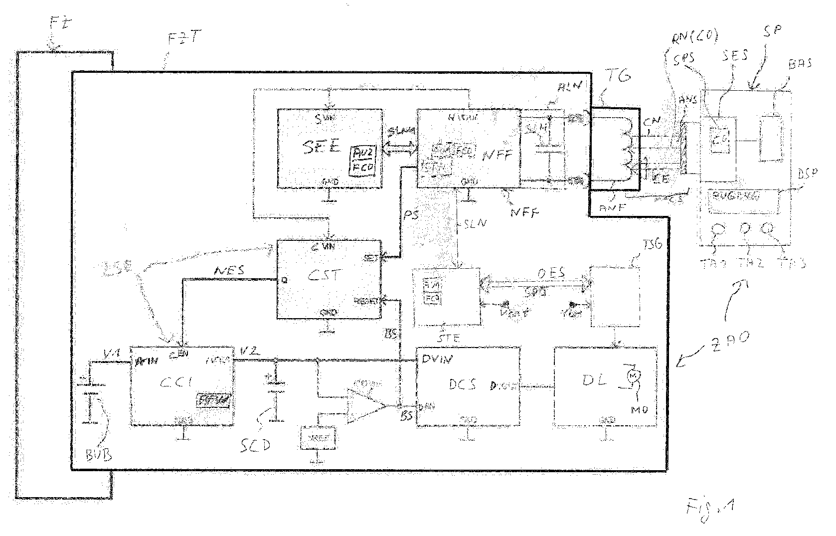
- FIG. 1 it is now up Fig. 1 referenced, in which an access arrangement ZAO is shown, which is designed for use in a vehicle FZ, in particular a motor vehicle.
- the access arrangement ZAO comprises a vehicle-side part which is accommodated in the vehicle FZ, in particular in a door FZT of the vehicle.
- the access arrangement ZAO further has a mobile part formed by a mobile identification transmitter, here in the design of a smart phone SP.
- a vehicle-side control device STE (for example in the form of a microcontroller) via a control line SLN send a signal to a vehicle-side transmitting / receiving device NFF, which then emits request signals CN at regular intervals.
- a control device STE instead of a control device STE (outside the vehicle-side transmitting / receiving device), a control device STN integrated in the vehicle-side transceiver device assumes the task of the control device STE.
- the vehicle-side transmitting / receiving device is an NFC module or an NFC reader NFF, which is installed adjacent to or at least partially in a door handle TG of the vehicle door FZT.
- This NFC reader NFF will now emit radio signals, in particular with a short range of about 10 cm, as request signals CN. These radio signals to request and as an answer lie in a frequency range according to an NFC standard, in particular at 13.56 MHz.
- the smartphone SP If there is now a radio-technical counterpart, such as the smartphone SP within the range of the request signals CN, it will respond to these request signals CN with one or more response signals RN.
- the vehicle-side (NFC) antenna ANF (as part of the vehicle-side transceiver) and located on the part of the smartphone SP, the smart-side (NFC) antenna ANF, which together form an NFC Form interface NFCS.
- the request signals CN are received by the smart-phone-side antenna ANS and forwarded to a smart-phone-side transmitting / receiving device SES.
- This comprises a memory device SPS, in which an identification code CO is stored.
- This code is received by the transceiver SES packed in a response signal RN, so that the identification code CO is transmitted back to the vehicle, more precisely to the antenna ANF. From there, the code is routed again via the control line SLN to the vehicle-side control device STE, where it is checked there by an authentication section AU1. In this test, the authentication code CO is compared with a code FCO stored in the authentication section AU1, whereby if the code matches, a positive result is obtained.
- the control device STE Upon receipt of a positive result of the check of the identification code CO, the control device STE outputs via a vehicle bus SPI a corresponding unlocking signal OES for a proper unlocking on a door control unit TSG.
- the door control unit TSG is supplied with the battery voltage Vbat by a vehicle-side battery via the electrical system or a vehicle-side power supply. If the door control unit TSG receives the proper unlocking signal OES, it will activate an engine MO of a door lock DL of the vehicle door FZT in order to unlock the vehicle door FZT or a corresponding locking mechanism. It is also conceivable that in addition to the door control unit TSG of the vehicle door FZT further door control devices are caused to unlock the corresponding door locks in any further vehicle doors and thus to allow user access to the vehicle or to the passenger compartment of the vehicle.
- the smartphone SP is a mobile identification device of a user.
- This Smartphone SP is capable of running multiple software-based applications ("Applications” or “Apps”).
- Applications or “Apps”
- a corresponding application can be started by means of one of the three buttons TA1, TA2 or TA3.
- the keys can be embodied as mechanical keys, or as so-called “softkeys” (touch-sensitive sections of a display device).
- the smartphone SP also has a display DSP, in which information about the currently running application can be seen.
- the smartphone-side transmitting / receiving device SES independently activates the emergency mode if, for example, within a certain time interval after starting the application "access” received no request signal CN from the vehicle-side antenna ANF.
- the emergency function has been activated in the smartphone SP in one of the ways described above. It is also assumed, as in Fig. 1 it is shown that the smartphone SP is brought near the door handle TG by the user.
- the smart-phone-side transmitting / receiving device SES is powered by a battery-side battery BAS electromagnetic energy in the form of the radio signals CE send in the direction of the vehicle-side antenna ANF.
- This antenna thus serves as a first portion of a vehicle-side power supply device for receiving wirelessly transmitted power and for converting the transmitted energy into electrical energy.
- the NFC reader NFF which can be regarded as the vehicle-side power supply device, is now operated in emergency mode not as a reading device, but in a transponder mode in which it receives (externally) supplied energy.
- the NFC reader NFF also has a second section ALN, which serves to charge a vehicle-mounted rechargeable electric energy storage device SCH in the form of a supercapacitor or ultracapacitor.
- This supercapacitor SCH has in the example a voltage of 5 volts and a capacity of 3.3 F.
- the smart phone-side transmitting / receiving device SES in regular (especially short) time intervals (eg at intervals of 300-400ms or permanent for a certain time) high-energy radio waves CE (eg with a power of 100mWatt) sends in the direction of the antenna ANF is this energy is further converted and thereby the supercapacitor SCH charged.
- the energy stored in the capacitor SCH can be used to supply energy to components of the access arrangement provided specifically for emergency operation.
- a voltage output NVOUT of the NFC reader NFF via its voltage input SVIN, as well as a voltage supply of a charge trigger circuit CST via the voltage input CVIN.
- the operation of the vehicle-side emergency control device SEE is now ensured via the supercapacitor SCH, this can begin to initiate an authentication process with respect to the smartphone SP.
- this can begin to initiate an authentication process with respect to the smartphone SP.
- a corresponding signal to the NFC reader NFF are output, which then with an exchange of request signals CN and response signals RN and a corresponding exchange of the identification code CO begins.
- the identification code CO transmitted by the smartphone can then be checked by an authentication section AU2 of the emergency control device SEE (corresponding to the authentication section AU1 of the control device STE).
- the authentication section AU2 determines that the smartphone SP applied to the door handle TG has access to the access arrangement ZAO Since a comparison of the sent with a response signal RN identification code CO with a stored in the emergency control device SEE code FCO was positive, it will notify this positive result of the review the NFC reader NFF, which then a release signal PS to an input SET of Charging trigger circuit CST creates. Through this release, the charge trigger circuit CST will apply a start signal NES to the one input CEN of the charging circuit CCI.
- a battery BUB can serve for example a button cell, which provides as voltage V1, for example 3 volts.
- the charging circuit CC1 further has a boost converter AFW for raising the voltage V1 to a voltage V2 of 5 volts.
- the charging circuit CCI begins with its operation, d. H. by raising the voltage V1 to the voltage V2 and providing this voltage V2 at the output IVOUT.
- This provided voltage V2 is then used to charge another on-board rechargeable electric energy storage device also in the form of a capacitor or supercapacitor SCD.
- the charge trigger circuit CST and the charge circuit CCI may be collectively referred to as a charge controller LSE.
- a monitoring circuit in the form of a comparator COMP monitors the charging of the supercapacitor SCD. In this case, upon reaching a certain threshold voltage VREF On the one hand, this completion of the charging process is communicated to the charge triggering circuit CST by the comparator COMP in that a corresponding termination signal BS is applied to an input REST of the charge triggering circuit CST.
- This termination signal BS causes the charge trigger circuit to stop the application of the start signal NES at the input CEN of the charging circuit CCI, so that further charging of the supercapacitor SCD is omitted.
- the termination signal BS at an input DEN of a switch DCS causes it to make a connection between its voltage input DVIN, which is connected to the supercapacitor SCD, and its voltage output DVOUT.
- the switch DCS now the door lock DL or a corresponding actuator or motor MO is operated to perform unlocking the door lock or a corresponding locking mechanism, and so as to achieve in an emergency unlocking the vehicle door FZT, and a Allow users to access the vehicle interior.
- the emergency control device SEE will be charged by the NFC interface NFCS in an emergency mode, after positive authentication directly the energy of the battery BUB for charging the supercapacitor SCD for the Operation of the door lock and the unlocking device DL can be used.
Landscapes
- Engineering & Computer Science (AREA)
- Power Engineering (AREA)
- Mechanical Engineering (AREA)
- Computer Networks & Wireless Communication (AREA)
- Physics & Mathematics (AREA)
- General Physics & Mathematics (AREA)
- Lock And Its Accessories (AREA)
Abstract
Eine Zugangsanordnung (ZAO) für ein Fahrzeug (FZ) umfasst eine fahrzeugseitige Entriegelungseinrichtung (CST, CCI) zum Betätigen eines Entsperrmechanismus. Ferner umfasst sie eine fahrzeugseitige aufladbare elektrische Energiespeichereinrichtung (SCD), die dafür eingerichtet ist, die Entriegelungseinrichtung mit Energie zu versorgen. Des Weiteren hat sie eine fahrzeugseitige aufgeladene elektrische Energiespeichereinrichtung (BUB), die dafür eingerichtet ist, die fahrzeugseitige aufladbare elektrische Energiespeichereinrichtung aufzuladen. Die Zugangsanordnung umfasst ferner eine Ladesteuereinrichtung (CST, CCI) zum Steuern des Ladevorgangs der fahrzeugseitigen aufladbaren elektrischen Energiespeichereinrichtung durch die fahrzeugseitige aufgeladene elektrische Energiespeichereinrichtung. Schließlich hat sie eine fahrzeugseitige Authentifizierungseinrichtung (SEE) zum Prüfen einer Zugangsberechtigung und zum Steuern der Ladesteuereinrichtung in Abhängigkeit der Prüfung der Zugangsberechtigung. Durch das Vorsehen einer bereits aufgeladenen, insbesondere vom Fahrzeugbordnetz unabhängigen, Energiespeichereinrichtung zum Versorgen einer Entriegelungseinrichtung über eine aufladbare elektrische Energiespeichereinrichtung kann bei einem Ausfall des Fahrzeugbordnetzes in einem Notlaufzustand schnell eine Entriegelung durchgeführt werden.
Description
Die vorliegende Erfindung betrifft eine Zugangsanordnung für ein Fahrzeug, insbesondere um eine Notentriegelung des Fahrzeugs bei Ausfall des Fahrzeugbordnetzes durchführen zu können. Ferner betrifft die Erfindung ein Fahrzeug mit einer gerade erwähnten Zugangsanordnung.The present invention relates to an access arrangement for a vehicle, in particular in order to perform an emergency release of the vehicle in case of failure of the vehicle electrical system. Furthermore, the invention relates to a vehicle with a just mentioned access arrangement.
Um einen unbefugten Zutritt zu einem Fahrzeug, insbesondere Kraftfahrzeug zu verhindern, verwenden moderne Zugangsberechtigungssysteme oder Zugangsanordnungen in Fahrzeugen elektronische Sicherungssysteme, bei denen zur Authentifizierung eines Benutzers eine Datenkommunikation zwischen einer ersten Kommunikationseinrichtung auf Fahrzeugseite mit einer zweiten Fahrzeugkommunikationseinrichtung in einem mobilen Identifikationsgeber des Benutzers, wie einem Schlüssel oder Schlüsselanhänger, erfolgt. Dabei werden bei einer aktiven Zugangsanordnung von dem mobilen Identifikationsgeber Steuersignale sowie ein Identifikationssignal, beispielsweise durch Drücken einer entsprechenden Taste durch den Benutzer des mobilen Identifikationsgebers, an das Fahrzeug gesendet, woraufhin dieses bei korrektem Identifikationscode entriegelt bzw. verriegelt wird.In order to prevent unauthorized access to a vehicle, in particular a motor vehicle, modern conditional access systems or access arrangements in vehicles use electronic security systems in which a user communicates with a second vehicle communication device in a user's mobile identification transmitter, such as a first communication device for authenticating a user Key or key fob, done. In this case, in an active access arrangement of the mobile identification transmitter control signals and an identification signal, for example, by pressing a corresponding button by the user of the mobile identification transmitter, sent to the vehicle, whereupon this is unlocked or locked with the correct identification code.
Bei einer sogenannten passiven Zugangsanordnung werden zunächst von einer ersten Kommunikationseinrichtung des Fahrzeugs in regelmäßigen Zeitabständen Anfragesignale mit einer bestimmten Feldstärke ausgesendet, um zu überprüfen, ob sich ein mobiler Identifikationsgeber in einem Annäherungsbereich bzw. in einem Zugangsbereich (Entriegelungszone) um das Fahrzeug befindet. Nähert sich ein mobiler Identifikationsgeber dem Fahrzeug und kann schließlich dessen Anfragesignale empfangen, so wird er auf den Empfang eines Anfragesignals antworten, um einen Authentifizierungsvorgang einzuleiten.In a so-called passive access arrangement, request signals having a certain field strength are first emitted by a first communication device of the vehicle at regular intervals in order to check whether a mobile identification transmitter is located in an approach area or in an access area (unlocking zone) around the vehicle. When a mobile identification transmitter approaches the vehicle and can finally receive its request signals, so he will respond to the receipt of a request signal to initiate an authentication process.
Dabei werden Datentelegramme ausgetauscht, in denen der zweite mobile Identifikationsgeber seinen Authentifizierungscode dem Fahrzeug übermittelt. Bei erfolgreicher Überprüfung des Authentifizierungscodes ist es dann möglich, dass ein Benutzer, der sich direkt am Fahrzeug in dem Zugangsbereich befindet, durch Betätigen eines Türgriffs ein Entriegeln der entsprechenden Fahrzeugtür oder aller Fahrzeugtüren initiiert. Da hier kein aktives Betätigen eines mechanischen oder elektrischen Identifikationsgebers bzw. Schlüssels durch einen Benutzer vorgenommen werden muss, wird diese Art der Zugangsberechtigungsprüfung auch als passive Zugangsberechtigungsprüfung und die entsprechenden Zugangsberechtigungssysteme als passive elektronische Zugangsberechtigungssysteme oder passive Zugangsanordnungen bezeichnet.In this case, data telegrams are exchanged in which the second mobile identification transmitter transmits its authentication code to the vehicle. Upon successful verification of the authentication code, it is then possible for a user located directly on the vehicle in the access area to initiate unlocking of the corresponding vehicle door or all vehicle doors by actuating a door handle. Since no active operation of a mechanical or electrical identification transmitter or key has to be carried out by a user, this type of access authorization test is also referred to as a passive access authorization test and the corresponding conditional access systems as passive electronic access authorization systems or passive access arrangements.
Wie gerade erwähnt, ist es insbesondere für passive Zugangsanordnungen nötig, dass eine fahrzeugseitige Kommunikationseinrichtung Signale zum mobilen Identifikationsgeber des Benutzers aussendet. Dies ist jedoch in dem Fall nicht mehr möglich, bei dem das Bordnetz des Fahrzeugs (gespeist durch eine Fahrzeugbatterie), das in der Regel die fahrzeugseitige Kommunikationseinrichtung mit Energie versorgt, ausfällt. Eine Möglichkeit des Ausfalls kann daher rühren, dass die das Bordnetz versorgende Fahrzeugbatterie leer ist bzw. keine ausreichende Spannung mehr bereitstellt. Zu diesem Zweck ist es denkbar, einen mobilen Identifikationsgeber mit einem mechanischen Notschlüssel zu versehen, der das Öffnen des Fahrzeugs über eine mechanische Schließvorrichtung am Fahrzeug ermöglicht. Damit die Schließvorrichtung manuell geöffnet werden kann, kann ein derartiger Notschlüssel neben dem Schlüsselbart einen ausreichend großen Schlüsselkopf aufweisen, damit das zum Öffnen des Schließmechanismus erforderliche Drehmoment aufgebracht werden kann. Ein derartig bemessener Schlüsselkopf beansprucht jedoch einen beträchtlichen Bauraum am Identifikationsgeber, sodass auf nachteilige Weise die Abmessungen des Identifikationsgebers durch diesen Notschlüssel bzw. Schlüsselkopf maßgeblich bestimmt und vergrößert werden. Ein derartiges Volumen eines Identifikationsgebers ist jedoch meist unerwünscht, da derartige Identifikationsgeber in vielen Fällen auch in Kleidertaschen eines Benutzers verwahrt werden und somit zum Ausbeulen der Taschen führen.As just mentioned, it is necessary, in particular for passive access arrangements, for a vehicle-side communication device to send signals to the user's mobile identification transmitter. However, this is no longer possible in the case where the electrical system of the vehicle (powered by a vehicle battery), which usually supplies power to the vehicle-side communication device, fails. One possibility of the failure may therefore be that the vehicle battery supplying the vehicle electrical system is empty or no longer provides sufficient voltage. For this purpose, it is conceivable to provide a mobile identification transmitter with a mechanical emergency key, which makes it possible to open the vehicle via a mechanical locking device on the vehicle. So that the closing device can be opened manually, such an emergency key next to the key bit can have a sufficiently large key head, so that the torque required to open the locking mechanism can be applied. However, such a sized key head claimed a considerable amount of space on the ID transmitter, so that the dimensions of the ID transmitter are significantly determined and increased by this emergency key or key head disadvantageously. However, such a volume of an identification transmitter is usually undesirable because such identification transmitter are stored in many cases in garment pockets of a user and thus lead to buckling of the pockets.
Somit besteht die Aufgabe der vorliegenden Erfindung darin, eine Möglichkeit zu schaffen, einen Zugang zum Fahrzeug bei Versagen der fahrzeugseitigen Stromversorgung auch ohne Notschlüssel zu schaffen.Thus, the object of the present invention is to provide a way to provide access to the vehicle in case of failure of the vehicle power supply even without emergency key.
Diese Aufgabe wird durch die Gegenstände der unabhängigen Ansprüche gelöst. Vorteilhafte Ausgestaltungen sind Gegenstand der Unteransprüche.This object is solved by the subject matters of the independent claims. Advantageous embodiments are the subject of the dependent claims.
Gemäß einem ersten Aspekt der Erfindung umfasst eine Zugangsanordnung für ein Fahrzeug, insbesondere ein Kraftfahrzeug, eine fahrzeugseitige Entriegelungseinrichtung zum Betätigen, insbesondere Entriegeln, eines Sperrmechanismus der Zugangsanordnung. Ferner umfasst sie eine fahrzeugseitige aufladbare elektrische Energiespeichereinrichtung, die dafür eingerichtet ist, die Entriegelungseinrichtung mit Energie zu versorgen. Überdies umfasst sie eine fahrzeugseitige aufgeladene elektrische Energiespeichereinrichtung, die dafür eingerichtet ist, die fahrzeugseitige aufladbare elektrische Energiespeichereinrichtung aufzuladen. Dabei ist es möglich, dass die fahrzeugseitige aufladbare elektrische Energiespeichereinrichtung nicht mit der bordeigenen Stromversorgung des Fahrzeugs verbunden ist, sondern von dieser unabhängig. Auch ist es möglich, dass die fahrzeugseitige aufgeladene elektrische Energiespeichereinrichtung nicht mit der bordeigenen Stromversorgung des Fahrzeugs verbunden ist. Die Zugangsanordnung umfasst des Weiteren eine Ladesteuereinrichtung zum Steuern des Ladevorgangs der fahrzeugseitigen aufladbaren elektrischen Energiespeichereinrichtung durch die fahrzeugseitige aufgeladene elektrische Energiespeichereinrichtung. Schließlich hat die Zugangsanordnung eine fahrzeugseitige Authentifizierungseinrichtung zum Prüfen und insbesondere auch Vollziehen einer Zugangsberechtigung und zum Steuern der Ladesteuereinrichtung in Abhängigkeit der Prüfung der Zugangsberechtigung. Durch das Vorsehen der fahrzeugseitigen aufgeladenen elektrischen Energiespeichereinrichtung und der Möglichkeit des gezielten Aufladens der fahrzeugseitigen aufladbaren elektrischen Energiespeichereinrichtung in einem "Notlauf-Zustand", bei dem das fahrzeugseitige Bordnetz bzw. die Fahrzeugbatterie gar keine oder nicht mehr ausreichende Energie zur Verfügung stellt, kann auch in diesem "Notlauf-Zustand" ohne gesonderten Notschlüssel eine Betätigung der fahrzeugseitigen Entriegelungseinrichtung erfolgen.According to a first aspect of the invention, an access arrangement for a vehicle, in particular a motor vehicle, comprises a vehicle-side unlocking device for actuating, in particular unlocking, a locking mechanism of the access arrangement. Furthermore, it comprises a vehicle-side rechargeable electrical energy storage device which is set up to supply the unlocking device with energy. Moreover, it includes a vehicle-side charged electric energy storage device configured to charge the vehicle-side rechargeable electric energy storage device. It is possible that the vehicle-mounted rechargeable electric energy storage device not with the on-board power supply of the Vehicle is connected, but independent of this. It is also possible that the vehicle-mounted charged electrical energy storage device is not connected to the on-board power supply of the vehicle. The access arrangement further comprises a charge control device for controlling the charging process of the vehicle-side rechargeable electric energy storage device by the vehicle-side charged electric energy storage device. Finally, the access arrangement has a vehicle-side authentication device for checking and in particular also executing an access authorization and for controlling the charging control device in dependence on the checking of the access authorization. By providing the vehicle-side charged electrical energy storage device and the possibility of targeted charging of the vehicle-side rechargeable electric energy storage device in a "runflat state" in which the vehicle-mounted electrical system or the vehicle battery provides no or no longer sufficient energy can also in this "emergency mode" without separate emergency key actuation of the vehicle-side unlocking done.
Gemäß einer Ausgestaltung kann es sich bei der fahrzeugseitigen aufgeladenen elektrischen Energiespeichereinrichtung um eine galvanische Zelle, insbesondere in der Form einer Primärzelle handeln, d. h. um eine nicht-aufladbare Primärzelle bzw. Batterie.According to one embodiment, the vehicle-side charged electrical energy storage device may be a galvanic cell, in particular in the form of a primary cell, d. H. around a non-rechargeable primary cell or battery.
Gemäß einer weiteren Ausgestaltung kann die fahrzeugseitige aufladbare elektrische Energiespeichereinrichtung einen Akku aufweisen, d. h. eine aufladbare galvanische Zelle bzw. Sekundärzelle. Es ist jedoch auch denkbar, dass sie einen Kondensator, vorzugsweise in der Form eines Superkondensators oder Ultrakondensators aufweist, der insbesondere eine große Leistungsdichte aufweist und schnell geladen und entladen werden kann.According to a further embodiment, the vehicle-side rechargeable electrical energy storage device may have a battery, ie a rechargeable galvanic cell or secondary cell. However, it is also conceivable that it has a capacitor, preferably in the form of a supercapacitor or ultracapacitor, in particular a large Power density and can be quickly charged and discharged.
Gemäß einer weiteren Ausgestaltung umfasst die Ladesteuereinrichtung ein Gleichspannungswandler in der Form eines Aufwärtswandlers, um eine von der aufgeladenen fahrzeugseitigen elektrischen Energiespeichereinrichtung bereitgestellte erste Spannung in eine zu dieser höheren zweiten Spannung zum Aufladen der fahrzeugseitigen aufladbaren elektrischen Energiespeichereinrichtung umzuwandeln. Auf diese Weise ist es möglich, eine Batterie als aufgeladene Energiespeichereinrichtung zu verwenden, um über den Aufwärtswandler beispielsweise einen Superkondensator schnell zu laden, damit über diesen die Entriegelungseinrichtung betätigt werden kann.According to a further embodiment, the charging control device comprises a DC-DC converter in the form of an up-converter to convert a first voltage provided by the charged vehicle-side electrical energy storage device into a higher second voltage for charging the vehicle-side rechargeable electric energy storage device. In this way, it is possible to use a battery as a charged energy storage device to quickly load, for example, a supercapacitor via the boost converter, so that the unlocking device can be actuated via this.
Gemäß einer weiteren Ausgestaltung der Zugangsanordnung umfasst diese ferner eine fahrzeugseitige Energiezufuhreinrichtung mit folgenden Merkmalen. Diese hat einen ersten Abschnitt zum Aufnehmen von drahtlos übertragener Energie und zum Umwandeln der übertragenen Energie in elektrische Energie. Ferner hat sie einen zweiten Abschnitt zum Versorgen der fahrzeugseitigen Authentifizierungseinrichtung mit der elektrischen Energie. Auf diese Weise ist es möglich, dass auch die Authentifizierungseinrichtung, beispielsweise bei einem kompletten Ausfall des fahrzeugseitigen Bordnetzes bzw. Fahrzeugbatterie, mittels der fahrzeugseitigen Energiezufuhreinrichtung durch Übertragen von Energie von außen versorgt werden kann.According to a further embodiment of the access arrangement, this further comprises a vehicle-side energy supply device with the following features. This has a first section for receiving wirelessly transmitted energy and converting the transmitted energy into electrical energy. Further, it has a second section for supplying the vehicle-side authentication device with the electric power. In this way, it is possible that the authentication device, for example, in a complete failure of the vehicle-side electrical system or vehicle battery, by means of the vehicle-side power supply device can be powered by transmitting energy from the outside.
Gemäß einer weiteren Ausgestaltung der Zugangsanordnung hat diese ferner eine weitere (zweite) fahrzeugseitige aufladbare elektrische Energiespeichereinrichtung, die mit dem zweiten Abschnitt der fahrzeugseitigen Energiezufuhreinrichtung verbunden ist, um aufgeladen zu werden. In diesem Zusammenhang ist es auch denkbar, dass die weitere fahrzeugseitige aufladbare elektrische Energiespeichereinrichtung ferner dafür eingerichtet ist, die fahrzeugseitige Authentifizierungseinrichtung mit Energie zu versorgen. Durch einen derartigen Aufbau ist es dann denkbar, dass die fahrzeugseitige Authentifizierungseinrichtung entweder direkt von dem zweiten Abschnitt der fahrzeugseitigen Energiezufuhreinrichtung mit Energie versorgt wird oder über die weitere fahrzeugseitige aufladbare elektrische Energiespeichereinrichtung, die ihrerseits über den zweiten Abschnitt der fahrzeugseitigen Energiezufuhreinrichtung mit Energie versorgt bzw. aufgeladen wird.According to another aspect of the access arrangement, it further has another (second) vehicle-side rechargeable electric energy storage device connected to the second portion of the vehicle-side power supply device to be charged. In this context It is also conceivable that the further vehicle-side rechargeable electrical energy storage device is further configured to provide the vehicle-side authentication device with energy. By such a structure, it is then conceivable that the vehicle-side authentication device is supplied with energy either directly from the second portion of the vehicle-side power supply or via the other vehicle-mounted rechargeable electric energy storage device, which in turn supplied with the second section of the vehicle-side power supply with energy or charged becomes.
Gemäß einer weiteren Ausgestaltung der fahrzeugseitigen Energiezufuhreinrichtung weist diese eine Funkschnittstelle auf. Dabei ist es denkbar, dass eine derartige Funkschnittstelle als Niederfrequenzfunkschnittstelle ausgebildet ist, die bei Frequenzen von ca. 125 kHz arbeitet. Es ist insbesondere jedoch auch denkbar, dass eine derartige Funkschnittstelle in der Form einer Nahbereichsfunkschnittstelle oder NFC-(Near Field Communication) Schnittstelle ausgebildet ist, um eine mittels Funk drahtlos übertragene Energie aufzunehmen. Wie später noch näher erläutert werden wird, kann eine derartige Energie von einem der Zugangsanordnung zugeordneten Identifikationsgeber bereitgestellt werden.According to a further embodiment of the vehicle-side energy supply device, this has a radio interface. It is conceivable that such a radio interface is designed as a low-frequency radio interface, which operates at frequencies of about 125 kHz. In particular, however, it is also conceivable that such a radio interface is designed in the form of a short-range radio interface or NFC (Near Field Communication) interface in order to record a wirelessly transmitted energy by radio. As will be explained in more detail later, such energy can be provided by an identification transmitter associated with the access arrangement.
Gemäß einer weiteren Ausgestaltung kann die fahrzeugseitige Energiezufuhreinrichtung auch eine Lichtschnittstelle umfassen. Dabei ist es insbesondere denkbar, dass diese Lichtschnittstelle in der Form einer Fotozelle (Solarzelle) ausgebildet ist, um eine mittels Licht drahtlos übertragene Energie insbesondere von einem der Zugangsanordnung zugeordneten Identifikationsgeber aufzunehmen. Dabei kann das Licht von einem Leuchtmittel des Identifikationsgebers, wie einer LED (Light Emitting Diode) stammen. Insbesondere bei Ausbilden des mobilen Identifikationsgebers als ein Mobiltelefon bzw. Smartphone, kann eine aktivierte Taschenlampenfunktion bzw. Blitzfunktion zur Bereitstellung des für die Energieversorgung verwendeten Lichts verwendet werden. Alternativ könnte die Energie auch von einer weiteren Lichtquelle stammen, beispielsweise von einer separaten Taschenlampe oder auch der Sonne. Im Fall der Verwendung von Sonnenlicht ist es auch denkbar, dass eine Authentifizierung und/oder Entriegelung stattfinden kann, wenn sowohl das Fahrzeug als auch der Identifikationsgeber keine ausreichende Batterieladung mehr haben. In diesem Fall muss der Benutzer dann warten, bis die Sonne scheint bzw. sie mittels einer fahrzeugseitigen Fotozelle/Solarzelle als erster Abschnitt der Energiezufuhreinrichtung die weitere fahrzeugseitige aufladbare Energiespeichereinrichtung aufgeladen hat bzw. der fahrzeugseitigen Authentifizierungseinrichtung genügend Energie zur Verfügung gestellt hat. Während der Energieübertragung könnte Licht auch zur Kommunikation für einen Authentifizierungsvorgang verwendet werden. Insbesondere ist hierbei auch Licht im Infrarot (IR)-Bereich möglich.According to a further embodiment, the vehicle-side energy supply device may also include a light interface. In this case, it is conceivable, in particular, for this light interface to be in the form of a photocell (solar cell) in order to receive an energy transmitted wirelessly by means of light, in particular from an identification transmitter assigned to the access arrangement. In this case, the light can come from a light source of the identification transmitter, such as an LED (Light Emitting Diode). Especially when training of the mobile identification transmitter as a mobile phone, an activated flashlight function may be used to provide the light used for the power supply. Alternatively, the energy could also originate from another light source, such as a separate flashlight or the sun. In the case of the use of sunlight, it is also conceivable that an authentication and / or unlocking can take place when both the vehicle and the identification transmitter no longer have sufficient battery charge. In this case, the user then has to wait until the sun shines or has charged the further vehicle-mounted rechargeable energy storage device by means of a vehicle-side photocell / solar cell as the first section of the energy supply device or has provided the vehicle-side authentication device with sufficient energy. During energy transfer, light could also be used for communication for an authentication process. In particular, in this case also light in the infrared (IR) range is possible.
Gemäß einer weiteren Ausgestaltung der Zugangsanordnung gibt die fahrzeugseitige Authentifizierungseinrichtung zum Vollziehen der Zugangsberechtigung ein Entriegelungssignal an die fahrzeugseitige Entriegelungseinrichtung zum Entriegeln eines Sperrmechanismus aus. Dabei wird insbesondere vorausgesetzt, dass eine Prüfung der Authentifizierungseinrichtung ein positives Ergebnis ergeben hat. Beispielsweise bedeutet dies, dass ein der Zugangsanordnung zugeordneter mobiler Identifikationsgeber zur Authentifizierungsprüfung seinen Code zu der Authentifizierungseinrichtung gesendet hat, wobei dieser mit einem in der Authentifizierungseinrichtung gespeicherten Code vergleichen wird und eine Übereinstimmung des übermittelten und des gespeicherten Codes zu einem positiven Authentifizierungsergebnis, und dann insbesondere zu einer Entriegelung führt.According to a further embodiment of the access arrangement, the vehicle-side authentication device for executing the access authorization outputs an unlocking signal to the vehicle-side unlocking device for unlocking a locking mechanism. In particular, it is assumed that a check of the authentication device has yielded a positive result. For example, this means that a mobile identification transmitter assigned to the access arrangement for authentication check has sent its code to the authentication device, this being compared with a code stored in the authentication device, and a match of the transmitted and the stored code to a positive authentication result, and then leads in particular to an unlocking.
Gemäß einer weiteren Ausgestaltung der Zugangsanordnung umfasst diese einen mobilen Identifikationsgeber zum Ausgeben bzw. Bereitstellen der drahtlos zu übertragenden Energie an die fahrzeugseitige Energiezufuhreinrichtung. Dieser mobile Identifikationsgeber kann derart ausgestaltet sein, dass er mit einem Benutzer bzw. von diesem mitführbar ist und als ein Schlüssel, Schlüsselanhänger, als ein Mobiltelefon, insbesondere ein Smartphone (intelligentes Telefon) oder als ein Fitnesstracker (Fitnessüberwachungseinrichtung, insbesondere um das Handgelenk getragen) usw. ausgebildet ist. Auf diese Weise kann der Benutzer beispielsweise einen Gegenstand seines täglichen Lebens auch dazu verwenden, eine Not-Entriegelung des Fahrzeugs bei Versagen des fahrzeugeigenen Bordnetzes durchzuführen.According to a further embodiment of the access arrangement, this comprises a mobile identification transmitter for outputting or providing the energy to be transmitted wirelessly to the vehicle-side energy supply device. This mobile identification transmitter can be designed in such a way that it can be carried along with it by a user and as a key, key fob, as a mobile phone, in particular a smartphone (smart phone) or as a fitness tracker (fitness monitoring device, in particular worn around the wrist). etc. is formed. In this way, the user can, for example, use an object of his daily life also to carry out an emergency unlocking of the vehicle in the event of a failure of the vehicle's onboard electrical system.
Es ist ferner denkbar, dass der mobile Identifikationsgeber, mit dem die Not-Entriegelung möglich ist, ferner dafür eingerichtet ist, mit der fahrzeugseitigen Authentifizierungseinrichtung zu kommunizieren, um eine Authentifizierung des mobilen Identifikationsgebers an der Zugangsanordnung bzw. an dem Fahrzeug durchzuführen. Wie oben bereits beschrieben, kann eine Authentifizierung dadurch stattfinden, dass ein oder mehrere Identifikationscodes zwischen dem mobilen Identifikationsgeber und der fahrzeugseitigen Authentifizierungseinrichtung ausgetauscht und mit vorbestimmten bzw. gespeicherten Codes verglichen werden.It is also conceivable that the mobile identification transmitter, with which the emergency unlocking is possible, is further configured to communicate with the vehicle-side authentication device in order to perform an authentication of the mobile identification transmitter to the access device or to the vehicle. As described above, an authentication can take place in that one or more identification codes are exchanged between the mobile identification transmitter and the vehicle-side authentication device and compared with predetermined or stored codes.
Gemäß einem weiteren Aspekt der Erfindung wird ein Fahrzeug mit einer oben dargestellten Zugangsanordnung oder einer Ausgestaltung hiervon geschaffen. Dabei kann das Fahrzeug zumindest eine Fahrzeugtür haben, in der die Komponenten der Zugangsanordnung angeordnet sind. Es ist ferner denkbar, dass die Fahrzeugtür einen Türgriff aufweist, in der die fahrzeugseitige Energiezufuhreinrichtung oder zumindest der erste Abschnitt der fahrzeugseitigen Energiezufuhreinrichtung vorgesehen sind.In accordance with another aspect of the invention, there is provided a vehicle having an access arrangement shown above or an embodiment thereof. In this case, the vehicle may have at least one vehicle door, in which the components of the access arrangement are arranged. It is also conceivable that the vehicle door has a door handle, in which the vehicle-side power supply means or at least the first portion of the vehicle-side power supply means are provided.
Details und vorteilhafte Ausgestaltungen der oben dargestellten Zugangsanordnung sind, soweit im Übrigen auf das Fahrzeug übertragbar, auch als vorteilhafte Ausgestaltungen des Fahrzeugs anzusehen und umgekehrt.Details and advantageous embodiments of the above-described access arrangement are, as far as applicable to the vehicle, also to be regarded as advantageous embodiments of the vehicle and vice versa.
Im Folgenden sollen nun beispielhafte Ausführungsformen der vorliegenden Erfindung bezugnehmend auf die beiliegende Zeichnung näher erläutert werden. Es zeigen:
- Fig. 1
- eine schematische Darstellung der wesentlichen Komponenten einer Zugangsanordnung gemäß einer Ausführungsform der Erfindung.
- Fig. 1
- a schematic representation of the essential components of an access arrangement according to an embodiment of the invention.
Es sei nun auf
In einem normalen bzw. ordnungsgemäßen Betrieb der Zugangsanordnung, bei dem eine fahrzeugseitige Batterie (nicht dargestellt) ein Bordnetz des Fahrzeugs mit Strom versorgt, sodass die wesentlichen Komponenten mit der Batteriespannung Vbat versorgt sind, wird eine fahrzeugseitige Steuereinrichtung STE (beispielsweise in der Form eines Microcontrollers) über eine Steuerleitung SLN ein Signal an eine fahrzeugseitige Sende-/Empfangseinrichtung NFF schicken, die dann in regelmäßigen Zeitabständen Anfragesignale CN aussendet. Es ist jedoch auch denkbar, dass anstelle einer Steuereinrichtung STE (außerhalb der fahrzeugseitigen Sende-/Empfangseinrichtung) ein in die fahrzeugseitige Sende-/Empfangseinrichtung integrierte Steuereinrichtung STN die Aufgabe der Steuereinrichtung STE übernimmt. Im vorliegenden Fall handelt es sich bei der fahrzeugseitigen Sende-/Empfangseinrichtung um ein NFC-Modul bzw. ein NFC-Lesegerät NFF, das benachbart zu oder zumindest teilweise in einen Türgriff TG der Fahrzeugtür FZT eingebaut ist. Dieses NFC-Lesegerät NFF wird nun Funksignale, insbesondere mit einer kurzen Reichweite von ca. 10 cm, als Anfragesignale CN aussenden. Diese Funksignale zur Anfrage sowie als Antwort liegen dabei in einem Frequenzbereich gemäß einem NFC-Standard, insbesondere bei 13,56 MHz.In a normal operation of the access arrangement, in which a vehicle-side battery (not shown), a vehicle electrical system of the vehicle supplied with electricity, so that the essential components with the battery voltage Vbat are supplied, a vehicle-side control device STE (for example in the form of a microcontroller) via a control line SLN send a signal to a vehicle-side transmitting / receiving device NFF, which then emits request signals CN at regular intervals. However, it is also conceivable that, instead of a control device STE (outside the vehicle-side transmitting / receiving device), a control device STN integrated in the vehicle-side transceiver device assumes the task of the control device STE. In the present case, the vehicle-side transmitting / receiving device is an NFC module or an NFC reader NFF, which is installed adjacent to or at least partially in a door handle TG of the vehicle door FZT. This NFC reader NFF will now emit radio signals, in particular with a short range of about 10 cm, as request signals CN. These radio signals to request and as an answer lie in a frequency range according to an NFC standard, in particular at 13.56 MHz.
Befindet sich nun ein funktechnisches Gegenstück, wie das Smartphone SP in Reichweite der Anfragesignale CN, so wird es auf diese Anfragesignale CN mit einem oder mehreren Antwortsignalen RN antworten. Zum Austausch dieser Anfrage- und Antwortsignale bestehen auf Fahrzeugseite die fahrzeugseitige (NFC-)Antenne ANF (als Teil der fahrzeugseitigen Sende-/Empfangseinrichtung) und befindet sich auf Seiten des Smartphones SP die smartphoneseitige (NFC-)Antenne ANF, die zusammen eine NFC-Schnittstelle NFCS bilden.If there is now a radio-technical counterpart, such as the smartphone SP within the range of the request signals CN, it will respond to these request signals CN with one or more response signals RN. To exchange these request and response signals consist on the vehicle side, the vehicle-side (NFC) antenna ANF (as part of the vehicle-side transceiver) and located on the part of the smartphone SP, the smart-side (NFC) antenna ANF, which together form an NFC Form interface NFCS.
Die Anfragesignale CN werden von der smartphoneseitigen Antenne ANS empfangen und zu einer smartphoneseitigen Sende-/Empfangseinrichtung SES geleitet. Diese umfasst eine Speichereinrichtung SPS, in der ein Identifizierungscode CO abgelegt ist. Dieser Code wird von der Sende-/Empfangseinrichtung SES in ein Antwortsignal RN verpackt, sodass der Identifizierungscode CO zurück zum Fahrzeug, genauer zur Antenne ANF übertragen wird. Von dort wird der Code wieder über die Steuerleitung SLN zur fahrzeugseitigen Steuereinrichtung STE geleitet, wobei er dort von einem Authentifizierungsabschnitt AU1 geprüft wird. Bei dieser Prüfung wird der Authentifizierungscode CO mit einem in dem Authentifizierungsabschnitt AU1 gespeicherten Code FCO verglichen, wobei bei Übereinstimmung des Codes ein positives Ergebnis erhalten wird.The request signals CN are received by the smart-phone-side antenna ANS and forwarded to a smart-phone-side transmitting / receiving device SES. This comprises a memory device SPS, in which an identification code CO is stored. This code is received by the transceiver SES packed in a response signal RN, so that the identification code CO is transmitted back to the vehicle, more precisely to the antenna ANF. From there, the code is routed again via the control line SLN to the vehicle-side control device STE, where it is checked there by an authentication section AU1. In this test, the authentication code CO is compared with a code FCO stored in the authentication section AU1, whereby if the code matches, a positive result is obtained.
Bei Erhalt eines positiven Ergebnisses der Prüfung des Identifizierungscodes CO gibt die Steuereinrichtung STE über einen Fahrzeugbus SPI ein entsprechendes Entriegelungssignal OES für eine ordnungsgemäße Entriegelung an einem Türsteuergerät TSG aus. Bei dem Fahrzeugbus kann es sich hierbei beispielsweise um einen sogenannten "serial peripheral interface" (SPI = serielle Peripherie Schnittstelle)-Bus handeln.Upon receipt of a positive result of the check of the identification code CO, the control device STE outputs via a vehicle bus SPI a corresponding unlocking signal OES for a proper unlocking on a door control unit TSG. The vehicle bus may be, for example, a so-called "serial peripheral interface" (SPI = serial peripheral interface) bus.
Das Türsteuergerät TSG wird, wie es angedeutet ist, von einer fahrzeugseitigen Batterie über das Bordnetz bzw. eine fahrzeugseitige Stromversorgung mit der Batteriespannung Vbat versorgt. Empfängt das Türsteuergerät TSG das ordnungsgemäße Entriegelungssignal OES, so wird es einen Motor MO eines Türschlosses DL der Fahrzeugtür FZT ansteuern, um die Fahrzeugtür FZT bzw. einen entsprechenden Sperrmechanismus zu entriegeln. Es ist auch denkbar, dass neben dem Türsteuergerät TSG der Fahrzeugtür FZT weitere Türsteuergeräte veranlasst werden, die entsprechenden Türschlösser bei eventueller weiterer Fahrzeugtüren zu entriegeln und somit einen Benutzerzugang zum Fahrzeug bzw. zur Fahrgastzelle des Fahrzeugs zu ermöglichen.As indicated, the door control unit TSG is supplied with the battery voltage Vbat by a vehicle-side battery via the electrical system or a vehicle-side power supply. If the door control unit TSG receives the proper unlocking signal OES, it will activate an engine MO of a door lock DL of the vehicle door FZT in order to unlock the vehicle door FZT or a corresponding locking mechanism. It is also conceivable that in addition to the door control unit TSG of the vehicle door FZT further door control devices are caused to unlock the corresponding door locks in any further vehicle doors and thus to allow user access to the vehicle or to the passenger compartment of the vehicle.
Neben diesem normalen oder ordnungsgemäßen Betrieb, der stattfindet, wenn die Fahrzeugbatterie und somit das Bordnetz des Fahrzeugs ausreichend Energie zur Verfügung stellt, ist auch ein Notlauf-Betrieb gemäß einer Ausführungsform der vorliegenden Erfindung insbesondere zum Durchführen einer Entriegelung denkbar.In addition to this normal or proper operation, which takes place when the vehicle battery and thus the electrical system the vehicle provides sufficient energy, a run-flat operation according to an embodiment of the present invention, in particular for performing an unlocking is conceivable.
Zu diesem Zweck der Einleitung eines Notlauf-Betriebs sei nun wieder auf das Smartphone SP als mobiler Identifikationsgeber eines Benutzers verwiesen. Dieses Smartphone SP ist in der Lage, mehrere Software-basierte Anwendungen ("Applications" oder "Apps") auszuführen. Beispielsweise ist es denkbar, dass eine entsprechende Anwendung mittels einer der drei Tasten TA1, TA2 oder TA3 gestartet werden kann. Die Tasten können dabei als mechanische Tasten, oder als sogenannte "Softkeys" (berührungsempfindliche Abschnitte einer Anzeigeeinrichtung) ausgeführt sein. Zur Kontrolle und zur Übersicht für einen Benutzer weist das Smartphone SP ferner eine Anzeige DSP auf, in der Informationen zur gerade ausgeführten Anwendung zu sehen sind. Beispielsweise ist es denkbar, dass durch Betätigen der Taste TA1 eine Anwendung mit dem Namen "Zugang") gestartet und ausgeführt wird, wobei die Ausführung der Anwendung "Zugang" gerade in der Anzeige DSP bestätigt wird. Dies ist nicht nur für den Notlauf denkbar, sondern auch für den ordnungsgemäßen Betrieb, der oben beschrieben worden ist.For this purpose, the initiation of a run-flat operation is now again referred to the smartphone SP as a mobile identification device of a user. This Smartphone SP is capable of running multiple software-based applications ("Applications" or "Apps"). For example, it is conceivable that a corresponding application can be started by means of one of the three buttons TA1, TA2 or TA3. The keys can be embodied as mechanical keys, or as so-called "softkeys" (touch-sensitive sections of a display device). For control and overview for a user, the smartphone SP also has a display DSP, in which information about the currently running application can be seen. For example, it is conceivable that by pressing the key TA1 an application with the name "access" is started and executed, the execution of the application "access" is currently confirmed in the display DSP. This is not only conceivable for the emergency operation, but also for the proper operation, which has been described above.
Während es möglich ist, dass bei dem ordnungsgemäßen Betrieb nach Starten der Anwendung "Zugang" das Smartphone SP an den Türgriff TG zum Austausch von Funksignalen gehalten werden muss, ist es denkbar, dass im Notlaufbetrieb ein Benutzer beispielsweise die Taste TA2 betätigt, um den Notlaufbetrieb zu aktivieren. Es ist jedoch auch denkbar, dass die smartphoneseitige Sende-/Empfangseinrichtung SES den Notlaufbetrieb eigenständig aktiviert, wenn sie beispielsweise innerhalb eines bestimmten Zeitintervalls nach Starten der Anwendung "Zugang" kein Anfragesignal CN seitens der fahrzeugseitigen Antenne ANF erhalten hat.While it is possible that in the proper operation after starting the application "access" the smartphone SP must be kept to the door handle TG for the exchange of radio signals, it is conceivable that in the emergency mode, a user presses, for example, the key TA2 to the emergency operation to activate. However, it is also conceivable that the smartphone-side transmitting / receiving device SES independently activates the emergency mode if, for example, within a certain time interval after starting the application "access" received no request signal CN from the vehicle-side antenna ANF.
Es wird nun davon ausgegangen, dass auf eine der oben beschriebenen Wege die Notlauffunktion im Smartphone SP aktiviert wurde. Außerdem wird angenommen, wie es in
Das NFC-Lesegerät NFF hat ferner einen zweiten Abschnitt ALN, der dazu dient, eine fahrzeugseitige aufladbare elektrische Energiespeichereinrichtung SCH in der Form eines Superkondensators oder Ultrakondensators aufzuladen. Dieser Superkondensator SCH hat im Beispiel eine Spannung von 5 Volt und eine Kapazität von 3,3 F.The NFC reader NFF also has a second section ALN, which serves to charge a vehicle-mounted rechargeable electric energy storage device SCH in the form of a supercapacitor or ultracapacitor. This supercapacitor SCH has in the example a voltage of 5 volts and a capacity of 3.3 F.
Während die smartphoneseitige Sende-/Empfangseinrichtung SES in regelmäßigen (insbesondere kurzen) Zeitabständen (z.B. in Intervallen von 300-400ms oder für eine bestimmte Zeit auch permanent) energiereiche Funkwellen CE (z.B. mit einer Leistung von 100mWatt) in Richtung der Antenne ANF sendet, wird diese Energie weiter umgewandelt und dadurch der Superkondensator SCH aufgeladen. Ist ein bestimmter Ladezustand erreicht, so kann die in dem Kondensator SCH gespeicherte Energie dafür genutzt werden, speziell für den Notlauf vorgesehene Komponenten der Zugangsanordnung mit Energie zu versorgen. Dabei erfolgt über einen Spannungsausgang NVOUT des NFC-Lesegeräts NFF eine Spannungsversorgung eines Notlaufsteuergeräts SEE über dessen Spannungseingang SVIN, sowie eine Spannungsversorgung einer Ladeauslöseschaltung CST über dessen Spannungseingang CVIN.While the smart phone-side transmitting / receiving device SES in regular (especially short) time intervals (eg at intervals of 300-400ms or permanent for a certain time) high-energy radio waves CE (eg with a power of 100mWatt) sends in the direction of the antenna ANF is this energy is further converted and thereby the supercapacitor SCH charged. Once a certain state of charge has been reached, the energy stored in the capacitor SCH can be used to supply energy to components of the access arrangement provided specifically for emergency operation. In this case, via a voltage output NVOUT of the NFC reader NFF, a voltage supply of a limp home control unit SEE via its voltage input SVIN, as well as a voltage supply of a charge trigger circuit CST via the voltage input CVIN.
Da nun über den Superkondensator SCH der Betrieb der fahrzeugseitigen Notsteuereinrichtung SEE sichergestellt ist, kann diese damit beginnen, einen Authentifizierungsvorgang bezüglich des Smartphones SP einzuleiten. Hierzu kann wie oben bezüglich des ordnungsgemäßen Betriebs über die Steuereinrichtung STE auch über die Notsteuereinrichtung SEE über eine Steuerleitung SLN1 ein entsprechendes Signal an das NFC-Lesegerät NFF ausgegeben werden, das daraufhin mit einem Austausch von Anfragesignalen CN und Antwortsignalen RN und einem entsprechenden Austausch des Identifizierungscodes CO beginnt. Der vom Smartphone übertragene Identifizierungscode CO kann dann von einem Authentifizierungsabschnitt AU2 der Notsteuereinrichtung SEE (entsprechend dem Authentifizierungsabschnitt AU1 der Steuereinrichtung STE) geprüft werden. Auf diese Weise ist es nun denkbar, dass trotz Versagens der bordeigenen Versorgungsspannung des Fahrzeugs durch Aufladen eines entsprechenden fahrzeugseitigen aufladbaren elektrischen Energiespeichers SCH eine Authentifizierungseinrichtung in der Form der fahrzeugseitigen Notsteuereinrichtung SEE mit dem entsprechenden Authentifizierungsabschnitt AU2 betrieben werden kann.Since the operation of the vehicle-side emergency control device SEE is now ensured via the supercapacitor SCH, this can begin to initiate an authentication process with respect to the smartphone SP. For this purpose, as above with respect to the proper operation via the control device STE via the emergency control device SEE via a control line SLN1 a corresponding signal to the NFC reader NFF are output, which then with an exchange of request signals CN and response signals RN and a corresponding exchange of the identification code CO begins. The identification code CO transmitted by the smartphone can then be checked by an authentication section AU2 of the emergency control device SEE (corresponding to the authentication section AU1 of the control device STE). In this way, it is now conceivable that despite failure of the on-board supply voltage of the vehicle by charging a corresponding vehicle-side rechargeable electric energy storage SCH an authentication device in the form of the vehicle-side emergency control device SEE can be operated with the corresponding authentication section AU2.
Stellt der Authentifizierungsabschnitt AU2 fest, dass am Türgriff TG angelegtes Smartphone SP zur Zugangsanordnung ZAO gehört, da ein Vergleich des mit einem Antwortsignal RN mitgeschickten Identifizierungscode CO mit einem in der Notsteuereinrichtung SEE gespeicherten Code FCO positiv war, so wird sie dieses positive Ergebnis der Überprüfung dem NFC-Lesegerät NFF mitteilen, das daraufhin ein Freigabesignal PS an einen Eingang SET der Ladeauslöseschaltung CST anlegt. Durch diese Freigabe wird die Ladeauslöseschaltung CST ein Startsignal NES an die einen Eingang CEN der Ladeschaltung CCI anlegen.If the authentication section AU2 determines that the smartphone SP applied to the door handle TG has access to the access arrangement ZAO Since a comparison of the sent with a response signal RN identification code CO with a stored in the emergency control device SEE code FCO was positive, it will notify this positive result of the review the NFC reader NFF, which then a release signal PS to an input SET of Charging trigger circuit CST creates. Through this release, the charge trigger circuit CST will apply a start signal NES to the one input CEN of the charging circuit CCI.
An dieser Ladeschaltung CCI liegt an einem weiteren Eingang IVIN eine Spannung V1 an, die von einer fahrzeugseitigen aufgeladenen Energiespeichereinrichtung in der Form einer Batterie BUB (back-up battery = Sicherungsbatterie) bereitgestellt wird. Als eine derartige Batterie BUB kann beispielsweise eine Knopfzelle dienen, die als Spannung V1 beispielsweise 3 Volt bereitstellt. Die Ladeschaltung CC1 hat ferner einen Aufwärtswandler AFW, um die Spannung V1 in eine Spannung V2 von 5 Volt hochzusetzen. Mit Eintreffen des Startsignals NES am Eingang CEN beginnt die Ladeschaltung CCI mit ihrem Betrieb, d. h. mit dem Hochsetzen der Spannung V1 zur Spannung V2 und dem Bereitstellen dieser Spannung V2 an dem Ausgang IVOUT. Diese bereitgestellte Spannung V2 wird dann dazu verwendet, eine weitere fahrzeugseitige aufladbare elektrische Energiespeichereinrichtung ebenso in der Form eines Kondensators bzw. Superkondensators SCD aufzuladen.At this charging circuit CCI is at a further input IVIN a voltage V1, which is provided by a vehicle-side charged energy storage device in the form of a battery BUB (back-up battery = backup battery). As such a battery BUB can serve for example a button cell, which provides as voltage V1, for example 3 volts. The charging circuit CC1 further has a boost converter AFW for raising the voltage V1 to a voltage V2 of 5 volts. With the arrival of the start signal NES at the input CEN, the charging circuit CCI begins with its operation, d. H. by raising the voltage V1 to the voltage V2 and providing this voltage V2 at the output IVOUT. This provided voltage V2 is then used to charge another on-board rechargeable electric energy storage device also in the form of a capacitor or supercapacitor SCD.
Die Ladeauslöseschaltung CST und die Ladeschaltung CCI können zusammen auch als eine Ladesteuereinrichtung LSE bezeichnet werden.The charge trigger circuit CST and the charge circuit CCI may be collectively referred to as a charge controller LSE.
Eine Überwachungsschaltung in der Form eines Komperators COMP überwacht dabei das Aufladen des Superkondensators SCD. Dabei wird bei Erreichen einer bestimmten Schwellenspannung VREF durch den Komparator COMP einerseits diese Beendigung des Ladevorgangs an die Ladeauslöseschaltung CST mitgeteilt, indem ein entsprechendes Beendigungssignal BS an einem Eingang REST der Ladeauslöseschaltung CST angelegt wird. Dieses Beendigungssignal BS bewirkt, dass die Ladeauslöseschaltung das Anliegen des Startsignals NES am Eingang CEN der Ladeschaltung CCI beendet, sodass ein weiteres Aufladen des Superkondensators SCD unterbleibt.A monitoring circuit in the form of a comparator COMP monitors the charging of the supercapacitor SCD. In this case, upon reaching a certain threshold voltage VREF On the one hand, this completion of the charging process is communicated to the charge triggering circuit CST by the comparator COMP in that a corresponding termination signal BS is applied to an input REST of the charge triggering circuit CST. This termination signal BS causes the charge trigger circuit to stop the application of the start signal NES at the input CEN of the charging circuit CCI, so that further charging of the supercapacitor SCD is omitted.
Andererseits bewirkt das Beendigungssignal BS an einem Eingang DEN eines Schalters DCS, dass dieser eine Verbindung zwischen seinem Spannungseingang DVIN, der mit dem Superkondensator SCD verbunden ist, und seinem Spannungsausgang DVOUT herstellt. Durch dieses durchgängig Einschalten des Schalters DCS wird nun das Türschloss DL bzw. ein entsprechender Aktor oder Motor MO betrieben, um ein Entriegeln des Türschlosses bzw. eines entsprechenden Sperrmechanismus durchzuführen, und um so auch im Notfall ein Entriegeln der Fahrzeugtür FZT zu erreichen, und einen Benutzer dem Zugang zu dem Fahrzeuginneren zu ermöglichen.On the other hand, the termination signal BS at an input DEN of a switch DCS causes it to make a connection between its voltage input DVIN, which is connected to the supercapacitor SCD, and its voltage output DVOUT. Through this continuous switching of the switch DCS now the door lock DL or a corresponding actuator or motor MO is operated to perform unlocking the door lock or a corresponding locking mechanism, and so as to achieve in an emergency unlocking the vehicle door FZT, and a Allow users to access the vehicle interior.
Es sei nochmal abschließend bemerkt, dass gemäß einer Zugangsanordnung ZAO kein mechanischer Notschlüssel mehr in einem mobilen Identifikationsgeber (Smartphone) nötig ist. Zum anderen ist es denkbar, eine Notentriegelung auch bei völligem Versagen der bordeigenen Stromversorgung des Fahrzeugs zu ermöglichen. Durch das drahtlose Versorgen mit Energie des NFC-Lesegeräts und der Notsteuereinrichtung SEE direkt oder über den Superkondensator SCH auf der einen Seite und durch Betreiben der fahrzeugseitigen Entriegelungseinrichtung DL zum Betätigen des Sperrmechanismus MO versorgt durch die vom Bordnetz des Fahrzeugs unabhängigen Batterie BUB ist ein sicherer Betrieb der fahrzeugseitigen Entriegelungseinrichtung möglich.It should be finally concluded that according to an access arrangement ZAO no mechanical emergency key in a mobile identification transmitter (smartphone) is necessary. On the other hand, it is conceivable to enable an emergency release even in the case of complete failure of the on-board power supply of the vehicle. By wirelessly supplying power to the NFC reader and the emergency controller SEE directly or via the supercapacitor SCH on one side and operating the vehicle-side unlocking device DL to operate the locking mechanism MO powered by the battery independent from the vehicle electrical system BUB is safe operation the vehicle-side unlocking possible.
Aufgrund der Tatsache, dass mit der Batterie BUB eine bereits aufgeladener Energiespeichereinrichtung verwendet wird, wird in einem Notlaufbetrieb lediglich die Notsteuereinrichtung SEE durch die NFC-Schnittstelle NFCS aufzuladen sein, wobei nach positiver Authentifizierung unmittelbar die Energie der Batterie BUB zum Aufladen des Superkondensators SCD für den Betrieb des Türschlosses bzw. der Entriegelungseinrichtung DL verwendet werden kann.Due to the fact that an already charged energy storage device is used with the battery BUB, only the emergency control device SEE will be charged by the NFC interface NFCS in an emergency mode, after positive authentication directly the energy of the battery BUB for charging the supercapacitor SCD for the Operation of the door lock and the unlocking device DL can be used.
Schließlich ist bei der Zugangsanordnung gemäß der Ausführungsform der vorliegenden Erfindung zu nennen, dass für den Notlaufbetrieb (zum externen Versorgen der Notsteuereinrichtung SEE) ein von einem Benutzer im täglichen Leben verwendeter Gebrauchsgegenstand (wie ein Smartphone) verwendet werden kann, den der Benutzer in der Regel meist sowieso in betriebsbereitem Zustand mit sich führt.Finally, in the access arrangement according to the embodiment of the present invention, it should be mentioned that for emergency operation (for externally supplying the emergency control device SEE), a commodity used by a user in daily life (such as a smart phone) can be used as a rule usually with you in working condition.
Claims (14)
bei der die fahrzeugseitige aufgeladene elektrische Energiespeichereinrichtung (BUB) eine galvanische Zelle, insbesondere in der Form einer Primärzelle aufweist.Access arrangement according to claim 1,
in which the vehicle-side charged electrical energy storage device (BUB) has a galvanic cell, in particular in the form of a primary cell.
bei der die fahrzeugseitige aufladbare elektrische Energiespeichereinrichtung einen Akku oder einen Kondensator, insbesondere in der Form eines Superkondensators (SCD), umfasst.Access arrangement according to claim 1 or 2,
in which the vehicle-side rechargeable electrical energy storage device comprises a rechargeable battery or a capacitor, in particular in the form of a supercapacitor (SCD).
bei der die Ladesteuereinrichtung (CST, CCI) einen Gleichspannungswandler in der Form eines Aufwärtswandlers (AFW) aufweist, um eine von der aufgeladenen fahrzeugseitigen elektrischen Energiespeichereinrichtung (BUB) bereitgestellte erste Spannung (V1) in eine zu dieser höheren zweiten Spannung (V2) zum Aufladen der fahrzeugseitigen aufladbaren elektrischen Energiespeichereinrichtung (SCD) umzuwandeln.Access arrangement according to one of claims 1 to 3,
wherein the charging control means (CST, CCI) comprises a DC-DC converter in the form of an up-converter (AFW) for charging a first voltage (V1) provided by the charged vehicle-side electrical energy storage device (BUB) to a higher second voltage (V2) the vehicle-side rechargeable electric energy storage device (SCD) to convert.
die ferner eine fahrzeugseitige Energiezufuhreinrichtung (NFF) mit folgenden Merkmalen aufweist:
further comprising an on-vehicle power supply (NFF) having the following features:
die ferner eine weitere fahrzeugseitige aufladbare elektrische Energiespeichereinrichtung (SCH) aufweist, die mit dem zweiten Abschnitt (ALN) der fahrzeugseitigen Energiezufuhreinrichtung (NFF) verbunden ist, um aufgeladen zu werden.Access arrangement according to claim 5,
which further has another vehicle-side rechargeable electric energy storage device (SCH) connected to the second section (ALN) of the vehicle-side power supply device (NFF) to be charged.
bei der die eine weitere fahrzeugseitige aufladbare elektrische Energiespeichereinrichtung (SCH) ferner dafür eingerichtet ist, die fahrzeugseitige Authentifizierungseinrichtung (SEE) mit Energie zu versorgen.Access arrangement according to claim 6,
in which the further vehicle-side rechargeable electric energy storage device (SCH) is further configured to supply the vehicle-side authentication device (SEE) with energy.
bei der die fahrzeugseitige Energiezufuhreinrichtung (NFF) eine Funkschnittstelle, insbesondere in der Form einer NFC-Schnittstelle, umfasst, um eine mittels Funk drahtlos übertragene Energie (CE) aufzunehmen.Access arrangement according to one of claims 1 to 7,
in which the vehicle-side energy supply device (NFF) has a radio interface, in particular in the form of an NFC interface, to receive wirelessly transmitted radio (CE) energy.
bei der die fahrzeugseitige Energiezufuhreinrichtung eine Lichtschnittstelle, insbesondere in der Form einer Fotozelle, aufweist, um eine mittels Licht drahtlos übertragene Energie aufzunehmen.Access arrangement according to one of claims 1 to 8,
in which the vehicle-side energy supply device has a light interface, in particular in the form of a photocell, in order to receive an energy transmitted wirelessly by means of light.
bei dem die fahrzeugseitige Authentifizierungseinrichtung (SEE) zum Vollziehen der Zugangsberechtigung ein Entriegelungssignal (PS) zum Aktivieren der fahrzeugseitigen Entriegelungseinrichtung ausgibt.Access arrangement according to one of claims 1 to 9,
in which the vehicle-side authentication device (SEE) for executing the access authorization issues an unlocking signal (PS) for activating the vehicle-side unlocking device.
der ferner einen mobilen Identifikationsgeber (SP) zum Ausgeben der drahtlos zu übertragenen Energie (CE) an die fahrzeugseitige Energiezufuhreinrichtung (NFF, ANF) aufweist.Access arrangement according to one of claims 1 to 10,
further comprising a mobile identification transmitter (SP) for outputting the wirelessly transmitted energy (CE) to the vehicle-side power supply device (NFF, ANF).
bei der der mobile Identifikationsgeber (SP) ferner dafür eingerichtet ist, mit der fahrzeugseitigen Authentifizierungseinrichtung (SEE) eine Authentifizierung durchzuführen.Access arrangement according to claim 11,
in which the mobile identification transmitter (SP) is further configured to perform authentication with the vehicle-side authentication device (SEE).
bei der der mobile Identifikationsgeber als ein Schlüssel, Schlüsselanhänger, ein Mobiltelefon, ein Smartphone (SP) oder ein Fitnesstracker ausgebildet ist.Access arrangement according to claim 11 or 12,
in which the mobile identification transmitter is designed as a key, key fob, a mobile phone, a smartphone (SP) or a fitness tracker.
Priority Applications (4)
| Application Number | Priority Date | Filing Date | Title |
|---|---|---|---|
| EP17465536.5A EP3441267B1 (en) | 2017-08-11 | 2017-08-11 | Access arrangement for a vehicle |
| CN201880048509.XA CN110944883B (en) | 2017-08-11 | 2018-08-09 | Access device for a vehicle |
| PCT/EP2018/071664 WO2019030339A1 (en) | 2017-08-11 | 2018-08-09 | Access arrangement for a vehicle |
| US16/638,069 US10864893B2 (en) | 2017-08-11 | 2018-08-09 | Access arrangement for a vehicle |
Applications Claiming Priority (1)
| Application Number | Priority Date | Filing Date | Title |
|---|---|---|---|
| EP17465536.5A EP3441267B1 (en) | 2017-08-11 | 2017-08-11 | Access arrangement for a vehicle |
Publications (2)
| Publication Number | Publication Date |
|---|---|
| EP3441267A1 true EP3441267A1 (en) | 2019-02-13 |
| EP3441267B1 EP3441267B1 (en) | 2020-06-17 |
Family
ID=59811278
Family Applications (1)
| Application Number | Title | Priority Date | Filing Date |
|---|---|---|---|
| EP17465536.5A Active EP3441267B1 (en) | 2017-08-11 | 2017-08-11 | Access arrangement for a vehicle |
Country Status (4)
| Country | Link |
|---|---|
| US (1) | US10864893B2 (en) |
| EP (1) | EP3441267B1 (en) |
| CN (1) | CN110944883B (en) |
| WO (1) | WO2019030339A1 (en) |
Cited By (1)
| Publication number | Priority date | Publication date | Assignee | Title |
|---|---|---|---|---|
| WO2019179910A1 (en) * | 2018-03-19 | 2019-09-26 | Brose Fahrzeugteile Gmbh & Co. Kommanditgesellschaft, Bamberg | Control assembly for a motor vehicle door |
Families Citing this family (7)
| Publication number | Priority date | Publication date | Assignee | Title |
|---|---|---|---|---|
| CN113888776A (en) * | 2020-06-16 | 2022-01-04 | 比亚迪股份有限公司 | Vehicle emergency unlocking device, system, method and vehicle |
| US11951945B1 (en) * | 2020-11-20 | 2024-04-09 | Enterprise Electronics, Llc | NFC-based enclosure access using passive energy harvesting |
| US11741767B1 (en) * | 2020-11-20 | 2023-08-29 | Enterprise Electronics Llc | NFC-based enclosure access using passive energy harvesting |
| US11713022B1 (en) * | 2020-11-20 | 2023-08-01 | Enterprise Electronics Llc | NFC-based enclosure access using passive energy harvesting |
| US11769359B2 (en) * | 2021-07-22 | 2023-09-26 | Rivian Ip Holdings, Llc | Systems, structures, and methods for accessing power locked panels |
| DE102021128395A1 (en) | 2021-10-27 | 2023-04-27 | Elmos Semiconductor Se | Emergency unlocking system for electrically locked vehicle doors |
| US12247420B2 (en) | 2023-05-30 | 2025-03-11 | Stmicroelectronics International N.V. | Emergency vehicle door opening by harvesting energy from an external field |
Citations (7)
| Publication number | Priority date | Publication date | Assignee | Title |
|---|---|---|---|---|
| EP0584499A1 (en) * | 1992-08-25 | 1994-03-02 | Bayerische Motoren Werke Aktiengesellschaft | Door lock for motor vehicles |
| US20050062453A1 (en) * | 2003-08-21 | 2005-03-24 | Yoshinobu Sato | Method and system for controlling vehicle door position having reduced power supply current requirements |
| DE102005054111A1 (en) * | 2005-11-12 | 2007-05-16 | Marquardt Gmbh | Locking system e.g. door locking system, for e.g. car, has electrical system energy determining unit whose power supply is switched over to emergency battery in case of system`s energy loss, where battery has activatable battery |
| WO2010125306A2 (en) * | 2009-04-30 | 2010-11-04 | Pascal Metivier | External power supply system for a lock comprising nfc-type contactless communication means |
| DE102013007154A1 (en) * | 2012-05-15 | 2013-11-21 | GM Global Technology Operations, LLC (n.d. Ges. d. Staates Delaware) | Motor vehicle with a central locking system |
| DE202013103042U1 (en) * | 2013-07-09 | 2014-10-10 | Brose Fahrzeugteile Gmbh & Co. Kommanditgesellschaft, Hallstadt | Motor vehicle lock |
| DE202016105621U1 (en) * | 2015-10-12 | 2016-11-23 | Ford Global Technologies, Llc | Keyless vehicle systems |
Family Cites Families (5)
| Publication number | Priority date | Publication date | Assignee | Title |
|---|---|---|---|---|
| KR20140144174A (en) * | 2012-01-05 | 2014-12-18 | 아닥 플라스틱스 인코포레이티드 | Vehicle access system |
| JP5880582B2 (en) * | 2014-01-10 | 2016-03-09 | トヨタ自動車株式会社 | vehicle |
| US9805534B2 (en) * | 2014-12-23 | 2017-10-31 | Gate Labs Inc. | Increased security electronic lock |
| US10184272B2 (en) * | 2015-07-01 | 2019-01-22 | Dominick S. LEE | Installation-free rechargeable door locking apparatus, systems and methods |
| US10312721B2 (en) * | 2017-06-06 | 2019-06-04 | Ford Global Technologies, Llc | Vehicle unlocking systems devices and methods |
-
2017
- 2017-08-11 EP EP17465536.5A patent/EP3441267B1/en active Active
-
2018
- 2018-08-09 WO PCT/EP2018/071664 patent/WO2019030339A1/en not_active Ceased
- 2018-08-09 CN CN201880048509.XA patent/CN110944883B/en active Active
- 2018-08-09 US US16/638,069 patent/US10864893B2/en active Active
Patent Citations (7)
| Publication number | Priority date | Publication date | Assignee | Title |
|---|---|---|---|---|
| EP0584499A1 (en) * | 1992-08-25 | 1994-03-02 | Bayerische Motoren Werke Aktiengesellschaft | Door lock for motor vehicles |
| US20050062453A1 (en) * | 2003-08-21 | 2005-03-24 | Yoshinobu Sato | Method and system for controlling vehicle door position having reduced power supply current requirements |
| DE102005054111A1 (en) * | 2005-11-12 | 2007-05-16 | Marquardt Gmbh | Locking system e.g. door locking system, for e.g. car, has electrical system energy determining unit whose power supply is switched over to emergency battery in case of system`s energy loss, where battery has activatable battery |
| WO2010125306A2 (en) * | 2009-04-30 | 2010-11-04 | Pascal Metivier | External power supply system for a lock comprising nfc-type contactless communication means |
| DE102013007154A1 (en) * | 2012-05-15 | 2013-11-21 | GM Global Technology Operations, LLC (n.d. Ges. d. Staates Delaware) | Motor vehicle with a central locking system |
| DE202013103042U1 (en) * | 2013-07-09 | 2014-10-10 | Brose Fahrzeugteile Gmbh & Co. Kommanditgesellschaft, Hallstadt | Motor vehicle lock |
| DE202016105621U1 (en) * | 2015-10-12 | 2016-11-23 | Ford Global Technologies, Llc | Keyless vehicle systems |
Cited By (1)
| Publication number | Priority date | Publication date | Assignee | Title |
|---|---|---|---|---|
| WO2019179910A1 (en) * | 2018-03-19 | 2019-09-26 | Brose Fahrzeugteile Gmbh & Co. Kommanditgesellschaft, Bamberg | Control assembly for a motor vehicle door |
Also Published As
| Publication number | Publication date |
|---|---|
| US10864893B2 (en) | 2020-12-15 |
| EP3441267B1 (en) | 2020-06-17 |
| US20200216030A1 (en) | 2020-07-09 |
| WO2019030339A1 (en) | 2019-02-14 |
| CN110944883A (en) | 2020-03-31 |
| CN110944883B (en) | 2022-06-10 |
Similar Documents
| Publication | Publication Date | Title |
|---|---|---|
| EP3441267B1 (en) | Access arrangement for a vehicle | |
| DE102017214105B4 (en) | Access arrangement for a vehicle | |
| DE102013216099B4 (en) | SYSTEM FOR ACTIVATING A VEHICLE INTO A KEY IN STATE | |
| DE102007035904B4 (en) | User identification device | |
| DE102011116209A1 (en) | Device for activating and deactivating locking and control system for vehicle, has control unit for activating or deactivating vehicle key, where entirely or partially deactivatable vehicle key and control unit | |
| DE102015211445A1 (en) | Wireless charging system | |
| DE102007010583B4 (en) | Emergency unlocking of motor vehicles | |
| DE102012004000A1 (en) | Transponder key i.e. mobile telephone, for remote controlling of lock in door of motor car, has connector comprising set of contacts connected with source and another set of contacts connected with interface for transmission of information | |
| DE102017214109B4 (en) | Mobile identification transmitter | |
| EP3519254B1 (en) | Apparatus for determining the position of a mobile access device on the vehicle | |
| DE102017214099A1 (en) | Mobile identification transmitter | |
| WO2020239795A1 (en) | Unlocking system and lock assembly having such an unlocking system | |
| WO2010106092A1 (en) | Arrangement for unlocking a lock | |
| DE102015213984A1 (en) | Method for providing electrical energy for a locking control of a door device | |
| DE112020002302T5 (en) | RESERVE POWER SUPPLY AND AUTHENTICATION FOR ELECTRONIC LOCK | |
| DE102014104032A1 (en) | Sealed identification transmitter | |
| EP2814700B1 (en) | Portable identification transmitter for a passive access system of a motor vehicle and method for the energy-saving operation of the identification transmitter | |
| DE102017211418B3 (en) | motor vehicle | |
| WO2011006888A2 (en) | Portable remote control device | |
| WO2009040316A1 (en) | Keyless access system having emergency operation function | |
| DE102022204236B3 (en) | Emergency unlocking of a motor vehicle | |
| DE102017107108B4 (en) | Method and device for temporarily blocking a motor vehicle | |
| WO2019030385A1 (en) | METHOD FOR OPERATING A ACCESS ARRANGEMENT FOR A VEHICLE | |
| DE102017214038A1 (en) | Anti-theft device for a vehicle | |
| DE102016218618A1 (en) | Device and method for access and start verification in a vehicle |
Legal Events
| Date | Code | Title | Description |
|---|---|---|---|
| PUAI | Public reference made under article 153(3) epc to a published international application that has entered the european phase |
Free format text: ORIGINAL CODE: 0009012 |
|
| STAA | Information on the status of an ep patent application or granted ep patent |
Free format text: STATUS: THE APPLICATION HAS BEEN PUBLISHED |
|
| AK | Designated contracting states |
Kind code of ref document: A1 Designated state(s): AL AT BE BG CH CY CZ DE DK EE ES FI FR GB GR HR HU IE IS IT LI LT LU LV MC MK MT NL NO PL PT RO RS SE SI SK SM TR |
|
| AX | Request for extension of the european patent |
Extension state: BA ME |
|
| STAA | Information on the status of an ep patent application or granted ep patent |
Free format text: STATUS: REQUEST FOR EXAMINATION WAS MADE |
|
| 17P | Request for examination filed |
Effective date: 20190813 |
|
| RBV | Designated contracting states (corrected) |
Designated state(s): AL AT BE BG CH CY CZ DE DK EE ES FI FR GB GR HR HU IE IS IT LI LT LU LV MC MK MT NL NO PL PT RO RS SE SI SK SM TR |
|
| GRAP | Despatch of communication of intention to grant a patent |
Free format text: ORIGINAL CODE: EPIDOSNIGR1 |
|
| STAA | Information on the status of an ep patent application or granted ep patent |
Free format text: STATUS: GRANT OF PATENT IS INTENDED |
|
| INTG | Intention to grant announced |
Effective date: 20200116 |
|
| GRAS | Grant fee paid |
Free format text: ORIGINAL CODE: EPIDOSNIGR3 |
|
| GRAA | (expected) grant |
Free format text: ORIGINAL CODE: 0009210 |
|
| STAA | Information on the status of an ep patent application or granted ep patent |
Free format text: STATUS: THE PATENT HAS BEEN GRANTED |
|
| AK | Designated contracting states |
Kind code of ref document: B1 Designated state(s): AL AT BE BG CH CY CZ DE DK EE ES FI FR GB GR HR HU IE IS IT LI LT LU LV MC MK MT NL NO PL PT RO RS SE SI SK SM TR |
|
| REG | Reference to a national code |
Ref country code: GB Ref legal event code: FG4D Free format text: NOT ENGLISH |
|
| REG | Reference to a national code |
Ref country code: CH Ref legal event code: EP |
|
| REG | Reference to a national code |
Ref country code: DE Ref legal event code: R096 Ref document number: 502017005735 Country of ref document: DE |
|
| REG | Reference to a national code |
Ref country code: IE Ref legal event code: FG4D Free format text: LANGUAGE OF EP DOCUMENT: GERMAN |
|
| REG | Reference to a national code |
Ref country code: AT Ref legal event code: REF Ref document number: 1280929 Country of ref document: AT Kind code of ref document: T Effective date: 20200715 |
|
| PG25 | Lapsed in a contracting state [announced via postgrant information from national office to epo] |
Ref country code: GR Free format text: LAPSE BECAUSE OF FAILURE TO SUBMIT A TRANSLATION OF THE DESCRIPTION OR TO PAY THE FEE WITHIN THE PRESCRIBED TIME-LIMIT Effective date: 20200918 Ref country code: NO Free format text: LAPSE BECAUSE OF FAILURE TO SUBMIT A TRANSLATION OF THE DESCRIPTION OR TO PAY THE FEE WITHIN THE PRESCRIBED TIME-LIMIT Effective date: 20200917 Ref country code: LT Free format text: LAPSE BECAUSE OF FAILURE TO SUBMIT A TRANSLATION OF THE DESCRIPTION OR TO PAY THE FEE WITHIN THE PRESCRIBED TIME-LIMIT Effective date: 20200617 Ref country code: SE Free format text: LAPSE BECAUSE OF FAILURE TO SUBMIT A TRANSLATION OF THE DESCRIPTION OR TO PAY THE FEE WITHIN THE PRESCRIBED TIME-LIMIT Effective date: 20200617 Ref country code: FI Free format text: LAPSE BECAUSE OF FAILURE TO SUBMIT A TRANSLATION OF THE DESCRIPTION OR TO PAY THE FEE WITHIN THE PRESCRIBED TIME-LIMIT Effective date: 20200617 |
|
| REG | Reference to a national code |
Ref country code: LT Ref legal event code: MG4D |
|
| REG | Reference to a national code |
Ref country code: NL Ref legal event code: MP Effective date: 20200617 |
|
| PG25 | Lapsed in a contracting state [announced via postgrant information from national office to epo] |
Ref country code: BG Free format text: LAPSE BECAUSE OF FAILURE TO SUBMIT A TRANSLATION OF THE DESCRIPTION OR TO PAY THE FEE WITHIN THE PRESCRIBED TIME-LIMIT Effective date: 20200917 Ref country code: HR Free format text: LAPSE BECAUSE OF FAILURE TO SUBMIT A TRANSLATION OF THE DESCRIPTION OR TO PAY THE FEE WITHIN THE PRESCRIBED TIME-LIMIT Effective date: 20200617 Ref country code: LV Free format text: LAPSE BECAUSE OF FAILURE TO SUBMIT A TRANSLATION OF THE DESCRIPTION OR TO PAY THE FEE WITHIN THE PRESCRIBED TIME-LIMIT Effective date: 20200617 Ref country code: RS Free format text: LAPSE BECAUSE OF FAILURE TO SUBMIT A TRANSLATION OF THE DESCRIPTION OR TO PAY THE FEE WITHIN THE PRESCRIBED TIME-LIMIT Effective date: 20200617 |
|
| PG25 | Lapsed in a contracting state [announced via postgrant information from national office to epo] |
Ref country code: AL Free format text: LAPSE BECAUSE OF FAILURE TO SUBMIT A TRANSLATION OF THE DESCRIPTION OR TO PAY THE FEE WITHIN THE PRESCRIBED TIME-LIMIT Effective date: 20200617 Ref country code: NL Free format text: LAPSE BECAUSE OF FAILURE TO SUBMIT A TRANSLATION OF THE DESCRIPTION OR TO PAY THE FEE WITHIN THE PRESCRIBED TIME-LIMIT Effective date: 20200617 |
|
| PG25 | Lapsed in a contracting state [announced via postgrant information from national office to epo] |
Ref country code: PT Free format text: LAPSE BECAUSE OF FAILURE TO SUBMIT A TRANSLATION OF THE DESCRIPTION OR TO PAY THE FEE WITHIN THE PRESCRIBED TIME-LIMIT Effective date: 20201019 Ref country code: ES Free format text: LAPSE BECAUSE OF FAILURE TO SUBMIT A TRANSLATION OF THE DESCRIPTION OR TO PAY THE FEE WITHIN THE PRESCRIBED TIME-LIMIT Effective date: 20200617 Ref country code: RO Free format text: LAPSE BECAUSE OF FAILURE TO SUBMIT A TRANSLATION OF THE DESCRIPTION OR TO PAY THE FEE WITHIN THE PRESCRIBED TIME-LIMIT Effective date: 20200617 Ref country code: IT Free format text: LAPSE BECAUSE OF FAILURE TO SUBMIT A TRANSLATION OF THE DESCRIPTION OR TO PAY THE FEE WITHIN THE PRESCRIBED TIME-LIMIT Effective date: 20200617 Ref country code: CZ Free format text: LAPSE BECAUSE OF FAILURE TO SUBMIT A TRANSLATION OF THE DESCRIPTION OR TO PAY THE FEE WITHIN THE PRESCRIBED TIME-LIMIT Effective date: 20200617 Ref country code: SM Free format text: LAPSE BECAUSE OF FAILURE TO SUBMIT A TRANSLATION OF THE DESCRIPTION OR TO PAY THE FEE WITHIN THE PRESCRIBED TIME-LIMIT Effective date: 20200617 Ref country code: EE Free format text: LAPSE BECAUSE OF FAILURE TO SUBMIT A TRANSLATION OF THE DESCRIPTION OR TO PAY THE FEE WITHIN THE PRESCRIBED TIME-LIMIT Effective date: 20200617 |
|
| PG25 | Lapsed in a contracting state [announced via postgrant information from national office to epo] |
Ref country code: SK Free format text: LAPSE BECAUSE OF FAILURE TO SUBMIT A TRANSLATION OF THE DESCRIPTION OR TO PAY THE FEE WITHIN THE PRESCRIBED TIME-LIMIT Effective date: 20200617 Ref country code: PL Free format text: LAPSE BECAUSE OF FAILURE TO SUBMIT A TRANSLATION OF THE DESCRIPTION OR TO PAY THE FEE WITHIN THE PRESCRIBED TIME-LIMIT Effective date: 20200617 Ref country code: IS Free format text: LAPSE BECAUSE OF FAILURE TO SUBMIT A TRANSLATION OF THE DESCRIPTION OR TO PAY THE FEE WITHIN THE PRESCRIBED TIME-LIMIT Effective date: 20201017 |
|
| REG | Reference to a national code |
Ref country code: DE Ref legal event code: R097 Ref document number: 502017005735 Country of ref document: DE |
|
| PG25 | Lapsed in a contracting state [announced via postgrant information from national office to epo] |
Ref country code: MC Free format text: LAPSE BECAUSE OF FAILURE TO SUBMIT A TRANSLATION OF THE DESCRIPTION OR TO PAY THE FEE WITHIN THE PRESCRIBED TIME-LIMIT Effective date: 20200617 |
|
| REG | Reference to a national code |
Ref country code: CH Ref legal event code: PL |
|
| PLBE | No opposition filed within time limit |
Free format text: ORIGINAL CODE: 0009261 |
|
| STAA | Information on the status of an ep patent application or granted ep patent |
Free format text: STATUS: NO OPPOSITION FILED WITHIN TIME LIMIT |
|
| PG25 | Lapsed in a contracting state [announced via postgrant information from national office to epo] |
Ref country code: CH Free format text: LAPSE BECAUSE OF NON-PAYMENT OF DUE FEES Effective date: 20200831 Ref country code: DK Free format text: LAPSE BECAUSE OF FAILURE TO SUBMIT A TRANSLATION OF THE DESCRIPTION OR TO PAY THE FEE WITHIN THE PRESCRIBED TIME-LIMIT Effective date: 20200617 Ref country code: LU Free format text: LAPSE BECAUSE OF NON-PAYMENT OF DUE FEES Effective date: 20200811 Ref country code: LI Free format text: LAPSE BECAUSE OF NON-PAYMENT OF DUE FEES Effective date: 20200831 |
|
| 26N | No opposition filed |
Effective date: 20210318 |
|
| REG | Reference to a national code |
Ref country code: BE Ref legal event code: MM Effective date: 20200831 |
|
| PG25 | Lapsed in a contracting state [announced via postgrant information from national office to epo] |
Ref country code: SI Free format text: LAPSE BECAUSE OF FAILURE TO SUBMIT A TRANSLATION OF THE DESCRIPTION OR TO PAY THE FEE WITHIN THE PRESCRIBED TIME-LIMIT Effective date: 20200617 |
|
| PG25 | Lapsed in a contracting state [announced via postgrant information from national office to epo] |
Ref country code: BE Free format text: LAPSE BECAUSE OF NON-PAYMENT OF DUE FEES Effective date: 20200831 Ref country code: IE Free format text: LAPSE BECAUSE OF NON-PAYMENT OF DUE FEES Effective date: 20200811 |
|
| PG25 | Lapsed in a contracting state [announced via postgrant information from national office to epo] |
Ref country code: TR Free format text: LAPSE BECAUSE OF FAILURE TO SUBMIT A TRANSLATION OF THE DESCRIPTION OR TO PAY THE FEE WITHIN THE PRESCRIBED TIME-LIMIT Effective date: 20200617 Ref country code: MT Free format text: LAPSE BECAUSE OF FAILURE TO SUBMIT A TRANSLATION OF THE DESCRIPTION OR TO PAY THE FEE WITHIN THE PRESCRIBED TIME-LIMIT Effective date: 20200617 Ref country code: CY Free format text: LAPSE BECAUSE OF FAILURE TO SUBMIT A TRANSLATION OF THE DESCRIPTION OR TO PAY THE FEE WITHIN THE PRESCRIBED TIME-LIMIT Effective date: 20200617 |
|
| PG25 | Lapsed in a contracting state [announced via postgrant information from national office to epo] |
Ref country code: MK Free format text: LAPSE BECAUSE OF FAILURE TO SUBMIT A TRANSLATION OF THE DESCRIPTION OR TO PAY THE FEE WITHIN THE PRESCRIBED TIME-LIMIT Effective date: 20200617 |
|
| REG | Reference to a national code |
Ref country code: DE Ref legal event code: R081 Ref document number: 502017005735 Country of ref document: DE Owner name: CONTINENTAL AUTOMOTIVE TECHNOLOGIES GMBH, DE Free format text: FORMER OWNER: CONTINENTAL AUTOMOTIVE GMBH, 30165 HANNOVER, DE Ref country code: DE Ref legal event code: R081 Ref document number: 502017005735 Country of ref document: DE Owner name: AUMOVIO GERMANY GMBH, DE Free format text: FORMER OWNER: CONTINENTAL AUTOMOTIVE GMBH, 30165 HANNOVER, DE |
|
| REG | Reference to a national code |
Ref country code: GB Ref legal event code: 732E Free format text: REGISTERED BETWEEN 20230223 AND 20230301 |
|
| REG | Reference to a national code |
Ref country code: AT Ref legal event code: MM01 Ref document number: 1280929 Country of ref document: AT Kind code of ref document: T Effective date: 20220811 |
|
| PG25 | Lapsed in a contracting state [announced via postgrant information from national office to epo] |
Ref country code: AT Free format text: LAPSE BECAUSE OF NON-PAYMENT OF DUE FEES Effective date: 20220811 |
|
| REG | Reference to a national code |
Ref country code: DE Ref legal event code: R081 Ref document number: 502017005735 Country of ref document: DE Owner name: CONTINENTAL AUTOMOTIVE TECHNOLOGIES GMBH, DE Free format text: FORMER OWNER: CONTINENTAL AUTOMOTIVE TECHNOLOGIES GMBH, 30165 HANNOVER, DE Ref country code: DE Ref legal event code: R081 Ref document number: 502017005735 Country of ref document: DE Owner name: AUMOVIO GERMANY GMBH, DE Free format text: FORMER OWNER: CONTINENTAL AUTOMOTIVE TECHNOLOGIES GMBH, 30165 HANNOVER, DE |
|
| PGFP | Annual fee paid to national office [announced via postgrant information from national office to epo] |
Ref country code: DE Payment date: 20250831 Year of fee payment: 9 |
|
| PGFP | Annual fee paid to national office [announced via postgrant information from national office to epo] |
Ref country code: GB Payment date: 20250821 Year of fee payment: 9 |
|
| PGFP | Annual fee paid to national office [announced via postgrant information from national office to epo] |
Ref country code: FR Payment date: 20250828 Year of fee payment: 9 |
|
| REG | Reference to a national code |
Ref country code: DE Ref legal event code: R081 Ref document number: 502017005735 Country of ref document: DE Owner name: AUMOVIO GERMANY GMBH, DE Free format text: FORMER OWNER: CONTINENTAL AUTOMOTIVE TECHNOLOGIES GMBH, 30175 HANNOVER, DE |