EP3441259A1 - Mobile chassis and tilting, removable cargo body - Google Patents
Mobile chassis and tilting, removable cargo body Download PDFInfo
- Publication number
- EP3441259A1 EP3441259A1 EP18186228.5A EP18186228A EP3441259A1 EP 3441259 A1 EP3441259 A1 EP 3441259A1 EP 18186228 A EP18186228 A EP 18186228A EP 3441259 A1 EP3441259 A1 EP 3441259A1
- Authority
- EP
- European Patent Office
- Prior art keywords
- loading box
- rolling frame
- rotation
- loading
- jaws
- Prior art date
- Legal status (The legal status is an assumption and is not a legal conclusion. Google has not performed a legal analysis and makes no representation as to the accuracy of the status listed.)
- Granted
Links
Images


Classifications
-
- B—PERFORMING OPERATIONS; TRANSPORTING
- B60—VEHICLES IN GENERAL
- B60P—VEHICLES ADAPTED FOR LOAD TRANSPORTATION OR TO TRANSPORT, TO CARRY, OR TO COMPRISE SPECIAL LOADS OR OBJECTS
- B60P1/00—Vehicles predominantly for transporting loads and modified to facilitate loading, consolidating the load, or unloading
- B60P1/04—Vehicles predominantly for transporting loads and modified to facilitate loading, consolidating the load, or unloading with a tipping movement of load-transporting element
- B60P1/16—Vehicles predominantly for transporting loads and modified to facilitate loading, consolidating the load, or unloading with a tipping movement of load-transporting element actuated by fluid-operated mechanisms
-
- B—PERFORMING OPERATIONS; TRANSPORTING
- B60—VEHICLES IN GENERAL
- B60P—VEHICLES ADAPTED FOR LOAD TRANSPORTATION OR TO TRANSPORT, TO CARRY, OR TO COMPRISE SPECIAL LOADS OR OBJECTS
- B60P1/00—Vehicles predominantly for transporting loads and modified to facilitate loading, consolidating the load, or unloading
- B60P1/64—Vehicles predominantly for transporting loads and modified to facilitate loading, consolidating the load, or unloading the load supporting or containing element being readily removable
Definitions
- the present invention relates to the field of tilting and removable loading boxes, in particular of the tipper type, that is to say, load boxes which are able to be mounted on a rolling chassis, in order to be able to be transported, which are adapted to pivot relative to the rolling frame about a horizontal axis of rotation, in particular to allow the gravity unloading of their contents, and which are removable relative to the rolling frame so as to be removed from the rolling frame and deposited at ground.
- any type of products and more particularly, but not exclusively bulk or semi-bulk products such as for example, and not limited to, bulk agricultural materials (cereals, beets, apples earth, ...), earthmoving materials or bulk waste (earth, sand, gravel ...)
- a loading box which is pivotally mounted on a rolling chassis, and which can be tilted upwards and backwards relative to the chassis, for example by means of at least one hydraulic cylinder, so as to allow its gravity unloading of the product.
- the rolling chassis may for example be the chassis of a carrier vehicle, or the chassis of a trailer or semi-trailer.
- the tilting loading box may for example be a tipper open at the top for its top loading or can be a closed container, or a tank or other tilting body.
- the type of loading box to be used may vary according to the particular nature of the products transported. For example, in the field of public works, it is necessary to use crates of lower height for their loading from the top with a shovel. In addition, in this field the gravel or rubble transported in a loading box cause significant abrasion phenomena, which requires the use of a heavier loading box whose bottom and sides have been reinforced to resist this abrasion. In the field of high volume transport, it is sought to optimize the weight ratio of the body / load volume, using load boxes that are lighter while having a large load volume. In the environmental field, the transport of waste or scrap imposes the use of reinforced loading boxes. Finally, the type of rear door of a box for unloading may also vary depending on the unloading site.
- US patent US 5,040,849 discloses an example of a loading box, dump type, which can be mounted removably and tilting on a rolling frame and can be removed from the rolling frame to be deposited on the ground by resting on crutches.
- the chassis has a tipping cylinder for tilting upwards and backwards the loading box relative to the chassis.
- an operator is forced to manually couple the movable rod of the tipping cylinder to the loading box, for example by means of a pin-type mechanical connection.
- the loading box carried by the rolling frame, it controls the cylinder actuating the pivoting part with rear lock function, so as to disconnect the frame and the axis of articulation of the loading box. Then an operator is forced to uncouple by hand the loading box and the rod of the hydraulic lift cylinder. Then the chassis is lowered vertically with respect to its wheels, so as to put the loading box on the ground by means of its crutches. Then we roll the chassis to remove it from the bottom of the loading box on the ground on his crutches.
- the present invention aims at proposing a new technical solution for removably mounting a tilting loading box on a rolling chassis, in order to be able to transport it to a storage and / or unloading area, and to withdraw from a chassis rolling a tilting loading box by depositing it on the ground, which technical solution overcomes all of the aforementioned drawbacks of the previously described technical solution of the prior art.
- the loading assembly of the invention comprises the two technical characteristics (a) and (b) referred to above.
- the raising and lowering operations of the rolling frame are carried out by means of at least the suspension of the chassis.
- the raising and lowering operations of the rolling frame are carried out by means of at least the suspension of the chassis.
- the subject of the invention is also a use of the abovementioned coupling device for rotatably coupling a loading box to a movable rod of a jack fitted to a rolling frame and a use of the abovementioned coupling device for rotatably coupling a loading box. to a rolling chassis.
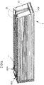
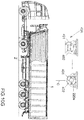
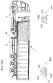
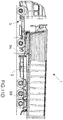
- FIG. 1 An example of a tipping loader 1 dump type, mounted and removably coupled to a chassis 2.
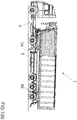
- the loading crate 1 has a shape substantially parallelepipedic, and is open at the top for loading from above.
- This type of loading box 1 can be used for the transport and / or storage of any type of product, and more particularly, but not exclusively, is suitable for the storage and / or transport of bulk or semi-bulk products such as that, for example, and not exhaustively, bulk agricultural materials (cereals, beets, potatoes, ...), earthmoving materials or bulk waste (earth, sand, gravel ).
- the loading box 1 is not necessarily of substantially parallelepiped shape, but may have a completely different shape, and for example a substantially cylindrical shape.
- the loading box 1 can be a closed container and can be intended for the transport and / or storage of any type of products.
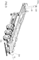
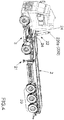
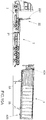
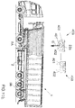
- the rolling chassis 2 is a semitrailer, which is adapted to be towed by a tractor vehicle 3 ( figure 4 ), which is supported by a rear running gear 20, and which is equipped at the front with a pair of retractable stands 21, used during the uncoupling operations of the rolling frame 2.
- rolling chassis any carrier structure capable of carrying a loading box and can roll relative to the ground, said carrier structure can be driven or towed.
- rolling chassis may for example be the chassis of a carrier vehicle, or the chassis of a trailer or semi-trailer.
- the rolling frame 2 comprises at the rear two horizontal axes of articulation 23a, which are oriented perpendicular to the longitudinal axis front / rear chassis, and which are aligned to define a horizontal axis of rotation 23.
- These two axes fixed hinge 23a are advantageously an integral part of the rolling frame 2 and thus allow effective recovery by the rolling frame 2 of the mechanical forces of the body 1, especially during the tipping operations of this body.
- the two hinge pins 23a can be replaced by a single longer fixed hinge pin of greater length, forming an integral part of the frame 2.
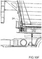
- the rolling frame 2 comprises at the front a lifting jack 22 central, telescopic simple effect, more commonly called tipping cylinder, and having a cylinder rod 220 oriented substantially vertically.
- the jack 22 makes it possible to actuate the rotational swing of the loading box 1 relative to the frame 2 about the rear axis of rotation 23, to allow the tipping of the body 1.
- the rod 220 of the jack 22 has a hinge axis 220a horizontal and oriented perpendicular to the longitudinal axis front / rear of the chassis 2.
- first coupling means 4 at the front of the box 1, which allow a coupling in removable, automatic rotation (that is to say without manual manipulation) and self-locking, the loading box 1 with the axis 220a at the end of the cylinder rod 22, and by means of second coupling means 4 'at the rear of the body 1, which allow a coupling in rotation removable, automatic and self-locking the loading box 1 with the hinge pins 23a of the rolling frame 2.
- the first coupling means 4 comprise a front coupler 40A, which is fixed, for example bolted, on the front wall 10 of the loading box 1, and which allows a coupling in removable, automatic and self-locking rotation, on the hinge axis 220a of the rod 220 of the tipping cylinder 22.
- the second coupling means 4 comprise two rear 40B couplers, which are fixed, for example bolted, at the rear and under the loading box 1, and which allow a coupling rotationally removable, automatic and self-locking, on the two hinge pins 23a of the frame rolling 2.
- the loading box is further equipped at the front with side stops 12 and the rear lateral abutment 11, which allow a lateral centering of the loading box 1 relative to the frame 2 during the laying operation of the body 1 on the chassis 2.
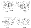
- a rear coupler 40B comprises a bearing 400 on which are mounted two jaws 401 and 402, which are articulated in rotation relative to the bearing 400, respectively by means of two hinge pins 401a and 402a defining two parallel axes of rotation 401b, 402b.
- This bearing 400 makes it possible to fix the coupler 40B to the loading box 1.
- a sole 404 adapted to cooperate with a stop 401e, 402e of each jaw 401, 402, so as to lock in rotation each jaw 402 in the open position ( figure 8F ).
- the rear coupler 40B further comprises locking means 405, whose function is to automatically lock the two jaws 401 and 402 in their closed position. figure 6 or 8A , in which they delimit between them a cylindrical passage 403 ( figure 6 ) for an axis.
- these locking means 405 comprise a rotary latch 405a, which is articulated in rotation on the hinge axis 401a of the jaw 401, and on which is mounted a 405b onboard peg.
- the axis of rotation of this lock 405a is equipped with a torsion spring whose function is, in the absence of stress, to elastically latch 405a rotated in the direction of rotation which is referenced by the arrow R in the figures, and which coincides with the direction of rotation at the opening of the jaw 401.
- the pin 405b is movable and guided in translation relative to the lock 405a, between on the one hand an end position of engagement, in which, depending on the rotational position of the lock 405a relative to the jaw 401, the pin 405b is positioned ( figure 8A and 9D ) in a locking groove 401c of the jaw 401 or ( figures 8D and 8E ) in an unlocking groove 401d of the jaw 401, and on the other hand an extreme position of disengagement ( Figure 8B, 8C , 8F , 9A, 9B, 9C ) in which it is completely disengaged from the locking groove 401c and the unlocking groove 401d.
- This rod 405b is also associated with a compression spring for exerting on the pin 405b an elastic restoring force pushing the pin 405b in its engagement position.
- the front coupler 40A is similar to the rear couplers 40B and differs mainly by the implementation of two pairs of jaws 401, 402 rotating which are spaced and aligned.
- the elements common to the couplers 40A and 40B have therefore been identified on the Figures 6 and 7 by the same references.
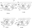
- the figure 8A represents the coupler 40A (respectively 40B) coupled in rotation and mechanically locked on the hinge pin 220a of the rod 220 of the cylinder 22 (respectively on a hinge axis 23a of the rolling frame 2).
- the operator manually rotates the latch 405a while pulling on the pin 405b, so that the latch 405A is no longer in abutment against the jaw 402.
- the pivoting of the lock 405a is continued until the pin 405b is positioned at the right of the unlocking groove 401d of the jaw 401, in which position the operator releases the pin 405b which is pushed back elastically (arrow P) by the associated compression spring and comes under the effect of return of this spring is positioned in the unlocking groove 401d of the jaw 401.
- the latch 401a is thus integral in rotation with the jaw 401, and the two jaws 401 and 402 are not more locked mechanically relative to each other by the lock 405a.
- the operator can move away from the coupler 40A (respectively 40B), the remainder of the sequence being automatic and no longer requiring manual manipulation of the coupler.
- the jaws 401 and 402 being unlocked, the opening of the jaws is effected by translational displacement of the axis 220a (respectively 23a) in a direction coinciding with the disengagement direction D, which on the figure 8E is vertical and downward, or conversely by moving in translation the jaws 401, 402 in an opposite direction which coincides with the coupling direction C.
- the two jaws 401 and 402 unlocked pivot away from one another, which allows to disengage the axis 220a (23a) of the jaws 401 and 402.
- the latch 405a pivots in the direction of rotation R; the lock 405a deposits the pin 405b on the bearing 400, the compression spring associated with the pin 405b now initially this one on the jaw 401, then in a second time on the bearing 400.
- the torsion spring pressure of the latch 405a provides an optimum opening angle of the jaws 401 and 402 and maintains them in contact with the sole 404.
- the rotational coupling of the coupler 40A (respectively 40B) with the hinge axis 220a (respectively 23a) is operated by translational displacement of the axis 220a (respectively 23a) in the coupling direction C, which is opposite the disengagement direction D referred to above or by displacing in translation the jaws 401, 402 in the disengagement direction D referred to above, so as to exert on the two jaws 401, 402, by means of the 220a axis (23a), a pressure oriented in the coupling direction C.
- the coupling direction C is vertical and upward.
- the empty loading box 1 is placed on the ground on its crutches 5A, 5B.
- the jaws 401, 402 of the couplers 40A and 40B are in their open position of the figure 8F .
- the rolling frame 2 is coupled to the tractor vehicle 3, the crutches 21 of the rolling frame 2 being retracted.
- the rod 220 of the tipping cylinder 22 is retracted.
- the chassis 2 / tractor unit 3 is positioned in front of the loading box 1, being substantially aligned and centered with respect to said loading box 1.
- the suspension of the chassis assembly 2 / tractor vehicle 3 is in the low position.
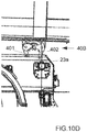
- the frame 2 / tractor unit 3 is moved back towards the loading box 1, until the undercarriage 2 is positioned under the loading box 1, with the hinge pins 23a of the chassis 2 positioned substantially vis-à-vis the open jaws 401, 402 of the rear couplers 40B ( FIG.10D ) and with the hinge axis 220a of the jack rod positioned substantially opposite the open jaws 401, 402 of the front coupler 40A ( FIG.10C ).
- the longitudinal positioning of the chassis 2 running under the loading box 1 along the longitudinal axis front / rear of the loading box 1 is controlled by means of the front longitudinal centering stops 24 of the rolling frame 2, and by moving back the rolling frame 2 until these longitudinal front centering stop 24 come tangent ( FIG.10C ) the front wall 10 of the loading box 1.
- the suspension of the towing vehicle 3 is brought into the high position, which has the effect of raising the front part of the rolling frame 2 in the region of the jack 22 with respect to the loading box 1.
- the front stops 24 of longitudinal centering of the rolling frame 2 cooperate with the front wall 10 of the body 1, so as to achieve a longitudinal centering of the front part of the loading box 1 relative to the rolling frame 2; the lateral stops 11 and 12 of the loading box 1 cooperate with the rolling frame 2 so as to achieve a lateral centering of the loading box 1 with respect to the rolling frame 2.
- the suspension of the rolling frame 2 is brought into the high position, which allows the lateral centering of the body on the chassis,
- the rise of the rolling frame 2 also causes the vertical linear translation upwards, that is to say the linear translation in the coupling direction C, of the axes of articulation 23a of the rolling frame 2.
- These hinge pins 23a come into contact with the jaws 401 and 402 of the rear couplers 40B, which automatically lock in the closed position on these axes of joints 23a, as previously described.
- the rear part of the loading box is thus coupled in rotation with the hinge pins 23a of the chassis 2.
- the crutches 5B are removed at the rear of the loading box 1. These rear crutches are for example removed from the loading box. When the crutches are articulated relative to the loading box 1, their removal can also be achieved by rotating them relative to the body so as to retract against the bottom wall of the body.
- the output of the rod 220 of the tipping cylinder 22 is controlled, which has the effect of causing the vertical linear translation upwards, that is to say the linear translation in the coupling direction C, of the axis hinge 220a at the end of this rod 220 of the tipping cylinder 22.
- This hinge pin 220a comes into contact with the jaws 401 and 402 of the front coupler 40A, and is guided by these jaws, which serve as a centralizer for the jack 22, and which automatically lock in the closed position on this hinge axis 220a, as previously described.
- the rod 220 of the tipping cylinder 22 is thus coupled in rotation with the loading box.
- the crutches 5A are removed at the front of the loading box 1. It controls the descent of the rod 220 of the tipping cylinder 22.
- the body 1 then rests on the chassis. Then we order the suspension of the chassis assembly 2 / tractor vehicle 3 to bring it to the intermediate position taxiing position between the high and low positions aforementioned.
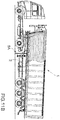
- the tipping cylinder 22 makes it possible in the usual manner to lift the front part of the loading box by controlling the outlet of its rod 220, which has the usual effect of rotating the loading box 1 with respect to the rolling frame 2, around the axis of rotation 23.
- This rotating rotation of the loading box is used mainly to discharge by gravity the contents of the box 1, once the door or doors at the back of the crate 1 were opened.
- the hinge pins 23a which define this axis of rotation 23 forming an integral part of the rolling frame 2, they advantageously allow recovery and transmission to the chassis efforts of the body 1, without these efforts n ' act on the locking of the rear couplers 40B.
- the empty loading box 1 being coupled to the rolling frame 2, itself coupled to the towing vehicle 3, if necessary disconnects the electrical connectors. It controls the suspension of the towing vehicle 3 to bring it up.
- the tipping cylinder 22 is controlled so as to release the rod 220a from the cylinder on a predefined stroke, for example 200mm, and the crutches 5A are installed under the front part of the loading box 1.
- the latch 405 of the front coupler 40A is manually unlocked and the suspension of the tractor vehicle 3 is controlled so as to lower it in the low position, which causes, in a first step, the lowering of the tractor 3, of the front part of the chassis 2 in the region of the cylinder 22, and the loading box 1, until the front part of the body 1 rests on the front legs 5A., and in a second time a lowering of the front part of the chassis 1 by compared to the front part of the box 1 on crutches.
- the front portion of the body resting on the legs 5A, this lowering of the frame 2, has the effect of causing the vertical linear translation downwards, that is to say the linear translation in the disengagement direction D of the front coupler 40A, of the hinge axis 220a at the end of the rod 220 of cylinder, and thus uncoupling the loading box 1 and the rod 220 of the cylinder 22 tipping, as previously described. Then we enter the rod 220 of the cylinder 22. The body 1 is then placed on its crutches before 5A.
- the suspension of the rolling frame 2 is controlled to bring it into the high position, which has the effect of raising the rear part of the rolling frame 2 in the region of the hinge pins 23a, and the stands 5B are installed at the rear of the cargo box 1.
- the latch 405 of the rear couplers 40B is manually unlocked and the suspension of the rolling chassis 2 is controlled so as to lower it in the low position, which first causes the chassis 2 and the loading box 1 to be lowered to to that part rear of the body 1 rests on the rear crutches 5B, and in a second time a lowering of the chassis relative to the body 1 placed on his front and rear crutches.
- This lowering of the frame 2 has the effect of causing the vertical linear translation downward, that is to say the linear translation in the disengagement direction D, of the hinge axes 23a of the frame, and thus of uncoupling the frame 2 and the loading box 1, as previously described.
- the body 1 is then placed on the front legs 5A and 5B rear.
- the rear crutches 5B are shorter than the crutches before 5A.
- the rolling chassis 2 is towed forwards so as to disengage it from the underside of the casing 1 placed on its crutches.
- the orientation of the loading box 1 is not substantially modified and the implementation of the invention does not require to equip the rolling frame with a special handling equipment, which is expensive and increases the dead weight on the chassis; the invention also does not require equipping the box with a reinforced and heavy rolling cradle as in the European patent applications EP 0 925 999 and EP 2 821 280 .
- the invention can therefore advantageously be implemented without penalizing the load useful for the load assembly (chassis and body), 40A front couplers and rear 40B are lightweight, reliable and inexpensive.
- the capacities of the existing suspension of the tractor unit 3 and the existing suspension of the frame 2 are provided for a full load capacity of the body 1. Therefore, the invention is not limited to the installation or removal an empty loading box 1, but can also be applied to the installation on a rolling chassis or removal on crutches of a loaded loading box, including a full box. It suffices to choose crutches 5A, 5B and crutch attachments to the body 1 adapted to stably support the weight of the empty or loaded crate.
- the invention is not limited to the particular 40A and 40B front jaw 40A, 402, which have been described with reference to the figures, but more generally extends to the implementation of self-locking coupling means, which comprise automatic locking means, said coupling means being adapted to take a locked closed position, under the effect of a pressure exerted in a coupling direction and with an automatic locking in their closed position by the means of coupling. locking, and the locking means being further unlockable, in particular manually.
- the horizontal articulation axis 220 a could be fixed to the loading box 1 while being oriented perpendicular to the longitudinal axis front / rear of the body 1, and the first coupling means 4 (coupler before 40A) could be attached to the cylinder rod (and no longer to the loading box 1).
- the hinge pin (s) 23a could be fixed to the loading box 1, being oriented perpendicular to the longitudinal axis front / rear of the body 1, and the second coupling means 4 ' (rear couplers 40B), could be attached to the chassis 2 (and no longer to the loading box 1).
- the second coupling means 4 ' can be replaced by non-automatic coupling means, which more generally allow coupling in rotation about said rotation axis 23, and in a removable manner, the loading box 1 to the chassis 2.
- the first coupling means 4 are automatic and self-locking.
- first coupling means 4 may be replaced by non-automatic coupling means, which more generally allow the rod 220 to be rotatably and removably coupled. from the cylinder to the loading box 1.
- second coupling means 4 ' are automatic and self-locking.
Landscapes
- Engineering & Computer Science (AREA)
- Transportation (AREA)
- Mechanical Engineering (AREA)
- Fittings On The Vehicle Exterior For Carrying Loads, And Devices For Holding Or Mounting Articles (AREA)
- Packaging Of Machine Parts And Wound Products (AREA)
- Handcart (AREA)
Abstract
L'ensemble de chargement comporte un châssis roulant (2) et une caisse de chargement (1) amovible Le châssis roulant (2) est équipé d'au moins un vérin (22) qui permet de faire pivoter la caisse de chargement (1) par rapport au châssis autour d'un axe de rotation horizontal. Ledit ensemble comporte au moins l'une des caractéristiques techniques (a) ou (b) suivantes: (a) ledit ensemble comprend des premiers moyens de couplage (4) autoverrouillables, qui sont fixés à la caisse de chargement (1) ou à la tige du vérin (22), de telle sorte que la tige du vérin est apte à être sortie de manière à exercer, sur les premiers moyens de couplage (4), une pression dans une direction de couplage les amenant automatiquement dans leur position de fermeture verrouillée, dans laquelle ils couplent en rotation la tige du vérin (22) à la caisse de chargement (1), les premiers moyens de couplage (4) étant en outre déverrouillables, ou (b) ledit ensemble comprend des deuxièmes moyens de couplage (4') autoverrouillables qui sont fixés à la caisse de chargement ou au châssis roulant (2), de telle sorte que le châssis roulant (2) est apte à être déplacé de manière à exercer sur les deuxièmes moyens de couplage (4') une pression dans la direction de couplage les amenant automatiquement dans leur position de fermeture verrouillée, dans laquelle ils couplent en rotation autour dudit axe de rotation horizontal (23) la caisse de chargement (1) au châssis roulant (2), les deuxièmes moyens de couplage (4') étant en outre déverrouillables.The loading unit comprises a rolling frame (2) and a removable loading box (1). The rolling frame (2) is equipped with at least one jack (22) which makes it possible to rotate the loading box (1). relative to the frame about a horizontal axis of rotation. Said assembly comprises at least one of the following technical characteristics (a) or (b): (a) said assembly comprises first self-locking coupling means (4), which are fixed to the loading box (1) or to the cylinder rod (22), so that the cylinder rod is able to be released so as to exert, on the first coupling means (4), a pressure in a coupling direction automatically bringing them into their locked closed position, in which they couple in rotation the rod of the jack (22) to the loading box (1), the first coupling means (4) being further unlockable, or (b) said assembly comprises second self-locking coupling means (4 ') which are fixed to the loading box or to the rolling frame (2), so that the rolling frame (2) is able to be moved in such a way as to exerting on the second coupling means (4 ') a pressure in the coupling direction automatically bringing them into their locked closed position, in which they couple in rotation about said horizontal axis of rotation (23) the loading box (1) to the rolling frame (2), the second coupling means (4 ') being further unlockable.
Description
La présente invention concerne le domaine des caisses de chargement basculantes et amovibles, notamment de type bennes basculantes, c'est-à-dire des caisses de chargement qui sont aptes à être montées sur un châssis roulant, afin de pourvoir être transportées, qui sont aptes à pivoter par rapport au châssis roulant autour d'un axe de rotation horizontal, afin notamment de permettre le déchargement par gravité de leur contenu, et qui sont amovibles par rapport au châssis roulant de manière à pouvoir être retirées du châssis roulant et déposées au sol.The present invention relates to the field of tilting and removable loading boxes, in particular of the tipper type, that is to say, load boxes which are able to be mounted on a rolling chassis, in order to be able to be transported, which are adapted to pivot relative to the rolling frame about a horizontal axis of rotation, in particular to allow the gravity unloading of their contents, and which are removable relative to the rolling frame so as to be removed from the rolling frame and deposited at ground.
Pour le stockage et/ou transport de tout type de produits, et plus particulièrement, mais non exclusivement des produits en vrac ou semi-vrac tels que par exemple, et de manière non exhaustive, des matières agricoles en vrac (céréales, betteraves, pommes de terre, ...), des matériaux de terrassement ou déchets en vrac (terre, sable, gravas...), Il est connu d'utiliser une caisse de chargement, qui est montée pivotante sur un châssis roulant, et qui peut être basculée vers le haut et vers l'arrière par rapport au châssis roulant, par exemple au moyen d'au moins un vérin hydraulique, de manière à permettre son déchargement par gravité du produit.For the storage and / or transport of any type of products, and more particularly, but not exclusively bulk or semi-bulk products such as for example, and not limited to, bulk agricultural materials (cereals, beets, apples earth, ...), earthmoving materials or bulk waste (earth, sand, gravel ...), It is known to use a loading box, which is pivotally mounted on a rolling chassis, and which can be tilted upwards and backwards relative to the chassis, for example by means of at least one hydraulic cylinder, so as to allow its gravity unloading of the product.
De manière non exhaustive, le châssis roulant peut par exemple être le châssis d'un véhicule porteur, ou le châssis d'une remorque ou semi-remorque.Non-exhaustively, the rolling chassis may for example be the chassis of a carrier vehicle, or the chassis of a trailer or semi-trailer.
La caisse de chargement basculante peut par exemple être une benne basculante ouverte en partie supérieure pour son chargement par le dessus ou peut être un conteneur fermé, ou une citerne ou toute autre carrosserie basculante.The tilting loading box may for example be a tipper open at the top for its top loading or can be a closed container, or a tank or other tilting body.
En fonction de la saisonnalité de l'activité, le type de caisse de chargement devant être utilisée peut varier en fonction notamment de la nature des produits transportés. Par exemple, dans le domaine des travaux publics, on est amené à utiliser des caisses de plus petite hauteur pour leur chargement par le haut avec une pelleteuse. En outre, dans ce domaine les graviers ou gravats transportés dans une caisse de chargement engendrent des phénomènes d'abrasion importants, ce qui oblige à utiliser une caisse de chargement plus lourde dont le fond et les côtés ont été renforcés pour résister à cette abrasion. Dans le domaine du transport grand volume, on cherche à optimiser le rapport poids de la caisse /volume de chargement, en utilisant des caisses de chargement qui sont plus légères tout en présentant un volume de chargement important. Dans le domaine environnemental, le transport de déchets ou ferrailles impose l'utilisation de caisses de chargement renforcées. Enfin le type de porte arrière d'une caisse pour son déchargement peut également varier en fonction du site de déchargement.Depending on the seasonality of the activity, the type of loading box to be used may vary according to the particular nature of the products transported. For example, in the field of public works, it is necessary to use crates of lower height for their loading from the top with a shovel. In addition, in this field the gravel or rubble transported in a loading box cause significant abrasion phenomena, which requires the use of a heavier loading box whose bottom and sides have been reinforced to resist this abrasion. In the field of high volume transport, it is sought to optimize the weight ratio of the body / load volume, using load boxes that are lighter while having a large load volume. In the environmental field, the transport of waste or scrap imposes the use of reinforced loading boxes. Finally, the type of rear door of a box for unloading may also vary depending on the unloading site.
Par conséquent, afin notamment de pouvoir utiliser les différents types de caisses de chargement connus, il est particulièrement utile de pouvoir monter de manière amovible une caisse de chargement basculante sur un châssis roulant, afin de pourvoir facilement changer de type de caisse de chargement et utiliser une caisse de chargement adaptée.Therefore, in particular in order to be able to use the various types of known loading boxes, it is particularly useful to be able to removably mount a tilting loading box on a rolling frame, in order to easily change the type of loading box and use a suitable loading box.
Le brevet américain
Pour monter la caisse de chargement sur le châssis, on positionne le châssis roulant sous la caisse de chargement, qui repose sur ses béquilles en étant supportée en hauteur par rapport au sol. Puis on lève verticalement, au moyen de deux vérins hydrauliques, le châssis par rapport à ses roues de manière à décoller du sol la caisse de chargement et ses béquilles. Ensuite, la caisse de chargement comportant à l'arrière un axe d'articulation, on couple le châssis à cet axe d'articulation au moyen d'une pièce pivotante à fonction de verrou, qui est actionnée par un vérin. Cette pièce pivotante à fonction de verrou permet de solidariser le châssis à l'axe d'articulation arrière de la caisse de chargement, avec un degré de liberté en rotation de la caisse de chargement par rapport au châssis. A l'avant et sous la caisse de chargement, le châssis comporte un vérin de bennage pour le basculement vers le haut et vers l'arrière de la caisse de chargement par rapport au châssis.To mount the loading box on the chassis, positioning the undercarriage under the loading box, which rests on its stands is supported in height relative to the ground. Then lifts vertically, by means of two hydraulic cylinders, the frame with respect to its wheels so as to take off from the ground the loading box and its crutches. Then, the loading box having a hinge axis at the rear, the frame is coupled to this axis of articulation by means of a pivoting piece with a latch function, which is actuated by a jack. This pivoting piece with lock function makes it possible to secure the frame to the rear hinge pin of the loading box, with a degree of freedom in rotation of the loading box relative to the chassis. At the front and under the cargo box, the chassis has a tipping cylinder for tilting upwards and backwards the loading box relative to the chassis.
Dans cette solution technique, un opérateur est contraint de coupler manuellement la tige mobile du vérin de bennage à la caisse de chargement, par exemple au moyen d'une liaison mécanique de type goupille.In this technical solution, an operator is forced to manually couple the movable rod of the tipping cylinder to the loading box, for example by means of a pin-type mechanical connection.
Pour déposer au sol la caisse de chargement portée par le châssis roulant, on commande le vérin actionnant la pièce pivotante à fonction de verrou arrière, de manière à désaccoupler le châssis et l'axe d'articulation de la caisse de chargement. Ensuite un opérateur est contraint de désaccoupler à la main la caisse de chargement et la tige du vérin hydraulique de levage. Puis on abaisse verticalement le châssis par rapport à ses roues, de manière à poser au sol la caisse de chargement par l'intermédiaire de ses béquilles. Ensuite on fait rouler au sol le châssis roulant pour le retirer du dessous de la caisse de chargement posée au sol sur ses béquilles.To deposit on the ground the loading box carried by the rolling frame, it controls the cylinder actuating the pivoting part with rear lock function, so as to disconnect the frame and the axis of articulation of the loading box. Then an operator is forced to uncouple by hand the loading box and the rod of the hydraulic lift cylinder. Then the chassis is lowered vertically with respect to its wheels, so as to put the loading box on the ground by means of its crutches. Then we roll the chassis to remove it from the bottom of the loading box on the ground on his crutches.
La solution technique susvisée décrite dans ce brevet américain
Cette solution technique nécessite de manière préjudiciable des interventions manuelles d'un opérateur pour coupler la tige du vérin de bennage à la caisse de chargement et pour désaccoupler la tige du vérin de bennage et la caisse de chargement. Or ces interventions manuelles sont fastidieuses et peuvent de surcroît présenter un danger corporel pour l'opérateur.This technical solution prejudicially requires manual intervention by an operator to couple the rod of the tipping cylinder to the loading box and to uncouple the stem of the tipping cylinder and the loading box. However, these manual interventions are tedious and can in addition present a bodily danger for the operator.
Le couplage et le désaccouplement de l'axe de rotation arrière de la caisse de chargement avec le châssis nécessitent la mise en oeuvre d'un vérin pour faire pivoter le verrou arrière, ce qui d'une part augmente le coût de la solution technique et rend la solution moins fiable et moins robuste dans le temps, ledit vérin d'actionnement du verrou arrière pivotant pouvant être déficient.The coupling and uncoupling of the rear axis of rotation of the loading box with the chassis requires the implementation of a jack to rotate the rear lock, which on the one hand increases the cost of the technical solution and makes the solution less reliable and less robust in time, said actuating cylinder of the pivoting rear latch may be deficient.
Lors du basculement vers le haut et vers l'arrière de la caisse de chargement, le poids de cette caisse de chargement, et le cas échéant le poids de son contenu, est de manière préjudiciable repris par la pièce pivotante à fonction de verrou arrière, ce qui rend cette solution peu robuste mécaniquement et susceptible d'engendrer un déverrouillage accidentel de la caisse de chargement par rapport au châssis sous l'effet du poids de cette caisse de chargement, et le cas échéant du poids de son contenu. En pratique, cette solution technique n'est donc pas adaptée pour des caisses de chargement de grand volume.When tilting up and down the crate loading, the weight of this loading box, and if necessary the weight of its contents, is prejudicially taken by the pivoting piece with rear lock function, which makes this solution not robust mechanically and likely to cause unlocking accidental loading box relative to the chassis under the effect of the weight of the loading box, and where appropriate the weight of its contents. In practice, this technical solution is therefore not suitable for large volume loading crates.
Enfin, les deux vérins pour la montée et l'abaissement du châssis sont dédiés uniquement à cette fonction, ce qui rend cette solution onéreuse et augmente le poids mort sur le châssis roulant.Finally, the two cylinders for raising and lowering the chassis are dedicated solely to this function, which makes this solution expensive and increases the dead weight on the chassis.
La présente invention vise à proposer une nouvelle solution technique pour monter de manière amovible une caisse de chargement basculante sur un châssis roulant, afin de pourvoir la transporter jusqu'à une zone de stockage et/ou de déchargement, et pour retirer d'un châssis roulant une caisse de chargement basculante en la déposant au sol, laquelle solution technique permet de pallier tout au partie des inconvénients susvisés de la solution technique précédemment décrite de l'art antérieur.The present invention aims at proposing a new technical solution for removably mounting a tilting loading box on a rolling chassis, in order to be able to transport it to a storage and / or unloading area, and to withdraw from a chassis rolling a tilting loading box by depositing it on the ground, which technical solution overcomes all of the aforementioned drawbacks of the previously described technical solution of the prior art.
L'invention a ainsi pour premier objet un ensemble de chargement comportant un châssis roulant et une caisse de chargement, qui est apte à être montée de manière amovible sur le châssis roulant en étant articulée en rotation par rapport au châssis roulant autour d'un axe de rotation horizontal ; ledit châssis roulant est équipé d'au moins un vérin, qui comporte une tige mobile, et qui permet, lorsque la caisse de chargement est montée sur le châssis et est couplée à la tige mobile du vérin, de faire pivoter la caisse de chargement par rapport au châssis autour dudit axe de rotation horizontal ; ledit ensemble comportant en outre au moins l'une des caractéristiques techniques (a) ou (b) suivantes:
- (a) ledit ensemble comprend des premiers moyens de couplage autoverrouillables, qui comportent des premiers moyens de verrouillage automatique, lesdits premiers moyens de couplage étant aptes à prendre une position de fermeture verrouillée, sous l'effet d'une pression exercée dans une direction de couplage (C) et avec un verrouillage automatique dans leur position de fermeture par les premiers moyens de verrouillage, les premiers moyens de couplage étant fixés à la caisse de chargement ou étant fixés à la tige du vérin, de telle sorte que la tige du vérin est apte à être déplacée, et de préférence à être sortie, de manière à exercer, sur les premiers moyens de couplage, une pression dans la direction de couplage (C) les amenant automatiquement dans leur position de fermeture verrouillée, dans laquelle ils couplent en rotation la tige du vérin à la caisse de chargement, les premiers moyens de couplage étant en outre déverrouillables, de manière à pouvoir désaccoupler la tige du vérin et la caisse de chargement en déplaçant la tige du vérin par rapport à la caisse de chargement, et ledit ensemble comprend des deuxièmes moyens de couplage qui permettent de coupler en rotation autour dudit axe de rotation horizontal, et de manière amovible, la caisse de chargement au châssis roulant (2),
ou - (b) ledit ensemble comprend des premiers moyens de couplage qui permettent de coupler en rotation et de manière amovible la tige du vérin à la caisse de chargement, et des deuxièmes moyens de couplage autoverrouillables, qui comportent des deuxièmes moyens de verrouillage, lesdits deuxièmes moyens de couplage étant aptes à prendre une position de fermeture verrouillée, sous l'effet d'une pression exercée dans une direction de couplage (C) et avec un verrouillage automatique dans leur position de fermeture par les deuxièmes moyens de verrouillage, les deuxièmes moyens de couplage étant fixés à la caisse de chargement ou étant fixés au châssis roulant de telle sorte que le châssis roulant est apte à être déplacé de manière à exercer sur les deuxièmes moyens de couplage une pression dans la direction de couplage (C) les amenant automatiquement dans leur position de fermeture verrouillée, dans laquelle ils couplent en rotation autour dudit axe de rotation horizontal la caisse de chargement au châssis roulant, les deuxièmes moyens de couplage étant en outre déverrouillables, de manière à pouvoir désaccoupler le châssis roulant et la caisse de chargement en déplaçant le châssis roulant par rapport à la caisse de chargement.
- (a) said set comprises first coupling means self-locking, which comprise first automatic locking means, said first coupling means being adapted to take a locked closed position, under the effect of a pressure exerted in a coupling direction (C) and with an automatic locking in their closing position by the first locking means, the first coupling means being fixed to the loading box or being fixed to the rod of the jack, so that the rod of the jack is able to be displaced, and preferably to be outlet, so as to exert, on the first coupling means, a pressure in the coupling direction (C) automatically bringing them into their locked closed position, in which they couple in rotation the rod of the cylinder to the loading box, the first coupling means being furthermore unlockable, so as to be able to uncouple the rod of the jack and the loading box in d moving the cylinder rod relative to the loading box, and said assembly comprises second coupling means which rotatably couple about said horizontal axis of rotation, and removably, the loading box to the rolling frame (2). ,
or - (b) said assembly comprises first coupling means which rotatably and removably couple the rod of the jack to the loading box, and second self-locking coupling means, which comprise second locking means, said second means coupling being able to take a locked closed position, under the effect of a pressure exerted in a coupling direction (C) and with an automatic locking in their closed position by the second locking means, the second locking means coupling being attached to the cash register loading or being fixed to the rolling frame so that the rolling frame is able to be moved so as to exert on the second coupling means a pressure in the coupling direction (C) automatically bringing them into their locked closed position, in which they couple in rotation about said horizontal axis of rotation the loading box to the rolling frame, the second coupling means being further unlockable, so as to be able to uncouple the rolling frame and the loading box by moving the rolling frame relative to the loading box.
Dans une variante préféré de réalisation, l'ensemble de chargement de l'invention comporte les deux caractéristiques techniques (a) et (b) susvisées.In a preferred embodiment, the loading assembly of the invention comprises the two technical characteristics (a) and (b) referred to above.
De manière facultative selon l'invention, l'ensemble de chargement de l'invention peut comporter les caractéristiques techniques optionnelles ci-après, prises isolément ou en combinaison :
- Les deuxièmes moyens de couplage sont fixés à la caisse de chargement ou sont fixés au châssis roulant, de telle sorte que ladite pression dans la direction de couplage (C) peut être exercée sur les deuxièmes moyens de couplage en déplaçant en hauteur le châssis roulant et le désaccouplement du châssis roulant et de la caisse de chargement peut être obtenu, une fois les deuxièmes moyens de couplage déverrouillés, en abaissant le châssis roulant.
- Ledit ensemble de chargement comporte au moins la caractéristique technique (a) et les premiers moyens de couplage sont fixés à la caisse de chargement.
- La tige du vérin comporte un axe d'articulation et les premiers moyens de couplage comportent au moins une paire de mâchoires, qui sont fixées à la caisse de chargement, qui sont articulées en rotation entre une position d'ouverture et une position de fermeture autour de l'axe d'articulation de la tige du vérin, et qui sont aptes à pivoter automatiquement de leur position d'ouverture à leur position de fermeture sous l'effet d'une pression orientée dans la direction de couplage (C) et exercée au moyen de l'axe d'articulation de la tige du vérin, lesdits premiers moyens de verrouillage permettant de verrouiller automatiquement les mâchoires en position de fermeture autour de l'axe d'articulation de la tige du vérin.
- Ledit ensemble de chargement comporte au moins la caractéristique technique (a) et les premiers moyens de couplage sont fixés à la tige du vérin.
- La caisse de chargement comporte un axe d'articulation et les premiers moyens de couplage comportent au moins une paire de mâchoires, qui sont fixées à la tige du vérin, qui sont articulées en rotation entre une position d'ouverture et une position de fermeture autour de l'axe d'articulation de la caisse de chargement, et qui sont aptes à pivoter automatiquement de leur position d'ouverture à leur position de fermeture sous l'effet d'une pression orientée dans la direction de couplage (C) et exercée au moyen de l'axe d'articulation de la caisse de chargement, lesdits premiers moyens de verrouillage permettant de verrouiller automatiquement les deux mâchoires en position de fermeture autour dudit axe d'articulation.
- Les premiers moyens de couplage comportent au moins deux paires de mâchoires, qui sont espacées et alignées.
- Ledit ensemble de chargement comporte au moins la caractéristique technique (b), et les deuxièmes moyens de couplage sont fixés à la caisse de chargement.
- Le châssis roulant comporte au moins un axe d'articulation définissant ledit axe de rotation horizontal de la caisse de chargement par rapport au châssis roulant ; les deuxièmes moyens de couplage comportent au moins une paire de mâchoires, qui sont fixées à la caisse de chargement, qui sont articulées en rotation entre une position d'ouverture et une position de fermeture autour de l'axe d'articulation du châssis roulant, et qui sont aptes à pivoter automatiquement de leur position d'ouverture à leur position de fermeture sous l'effet d'une pression orientée dans la direction de couplage (C) et exercée au moyen de l'axe d'articulation du châssis roulant, lesdits premiers moyens de verrouillage permettant de verrouiller automatiquement les deux mâchoires en position de fermeture autour de l'axe d'articulation du châssis roulant.
- Ledit ensemble de chargement comporte au moins la caractéristique technique (b), et les deuxièmes moyens de couplage sont fixés au châssis roulant.
- La caisse de chargement comporte au moins un axe d'articulation définissant ledit axe de rotation horizontal de la caisse de chargement par rapport au châssis roulant, et les deuxièmes moyens de couplage comportent au moins une paire de mâchoires, qui sont fixées au châssis roulant, qui sont articulées en rotation entre une position d'ouverture et une position de fermeture autour de l'axe d'articulation de la caisse de chargement, et qui sont aptes à pivoter automatiquement de leur position d'ouverture à leur position de fermeture sous l'effet d'une pression orientée dans la direction de couplage (C) et exercée au moyen de l'axe d'articulation de la caisse de chargement ; lesdits premiers moyens de verrouillage permettent de verrouiller automatiquement les deux mâchoires en position de fermeture autour de l'axe d'articulation du châssis roulant.
- Les deuxièmes moyens de couplage comportent au moins deux paires de mâchoires, qui sont espacées et alignées.
- Les mâchoires sont maintenues élastiquement en position d'ouverture lorsqu'elles ne sont plus verrouillées en position de fermeture.
- Les premiers moyens de verrouillage et/ou les deuxièmes moyens de verrouillage comportent un verrou pivotant, qui est apte à être entraîné en rotation jusqu'à une position de verrouillage par une première mâchoire lorsque les mâchoires pivotent de leur position d'ouverture à leur position de fermeture, et qui permet dans cette position de verrouillage un blocage en rotation des deux mâchoires en position de fermeture ; le verrou peut être actionné en rotation, notamment manuellement, jusque dans une position de déverrouillage dans laquelle les deux mâchoires ne sont pas bloquées en rotation.
- La deuxième mâchoire comporte une gorge de verrouillage, dans lequel le verrou pivotant embarque une pige, qui est coulissante et rappelée élastiquement en position d'engagement par un moyen de rappel élastique, de type ressort de compression ; le verrou pivotant en combinaison avec le moyen de rappel élastique de la pige est apte, au cours de sa rotation vers sa position de verrouillage, à entraîner la pige jusque dans la gorge de verrouillage lorsque les mâchoires pivotent de leur position d'ouverture à leur position de fermeture ; la pige, une fois positionnée dans la gorge de verrouillage, permet de solidariser en rotation le verrou et la deuxième mâchoire ; lorsque les mâchoires sont verrouillées, la pige peut être actionnée, notamment manuellement, de manière à coulisser en dehors de ladite gorge de verrouillage et le verrou peut être pivoté par rapport à la deuxième mâchoire de manière à déverrouiller en rotation les mâchoires.
- La deuxième mâchoire comporte également une gorge de déverrouillage, dans lequel le verrou pivotant en combinaison avec le moyen de rappel élastique de la pige est apte, au cours de sa rotation forcée permettant de déverrouiller les mâchoires, à entraîner la pige jusque dans la gorge de déverrouillage ; la pige, une fois positionnée dans la gorge de déverrouillage, permet de solidariser en rotation le verrou et la deuxième mâchoire, les deux mâchoires étant déverrouillées en rotation.
- Le verrou est équipé d'un moyen de rappel élastique, de type ressort de torsion, qui permet de faire pivoter le verrou en appui sur les deux mâchoires pour les maintenir en butée en position d'ouverture.
- Une fois les deux mâchoires verrouillées en position de fermeture, avec la pige positionnée dans la gorge de verrouillage de la deuxième mâchoire, la deuxième mâchoire (401) est verrouillée en rotation dans les deux sens par rapport au verrou, le verrou bloque en rotation la première mâchoire dans le sens de rotation de son ouverture et la première mâchoire bloque en rotation la deuxième mâchoire dans le sens de rotation de sa fermeture.
- Ledit ensemble de chargement comporte des béquilles permettant de supporter au sol la caisse de chargement, en la surélevant d'une hauteur suffisante pour permettre un positionnement du châssis roulant sous la caisse de chargement supportée par lesdites béquilles.
- La caisse de chargement et le châssis roulant comportent des moyens de centrage, qui permettent un centrage longitudinal et un centrage latéral de la caisse de chargement sur le châssis roulant.
- Ledit ensemble de chargement comporte les deux caractéristiques techniques (a) et (b).
- The second coupling means are fixed to the loading box or are fixed to the rolling frame, in such a way that said pressure in the coupling direction (C) can be exerted on the second coupling means by displacing the rolling frame in height and the uncoupling of the rolling frame and the loading box can be obtained, once the second coupling means are unlocked, by lowering the rolling frame.
- Said loading assembly comprises at least the technical characteristic (a) and the first coupling means are fixed to the loading box.
- The rod of the jack comprises a hinge pin and the first coupling means comprise at least one pair of jaws, which are fixed to the loading box, which are articulated in rotation between an open position and a closed position around of the axis of articulation of the cylinder rod, and which are able to rotate automatically from their open position to their closed position under the effect of a pressure oriented in the coupling direction (C) and exerted by means of the axis of articulation of the cylinder rod, said first means of lock for automatically locking the jaws in the closed position about the axis of articulation of the cylinder rod.
- Said loading assembly comprises at least the technical characteristic (a) and the first coupling means are fixed to the cylinder rod.
- The loading box comprises a hinge pin and the first coupling means comprise at least one pair of jaws, which are fixed to the rod of the jack, which are articulated in rotation between an open position and a closed position around of the hinge axis of the loading box, and which are able to automatically pivot from their open position to their closed position under the effect of a pressure oriented in the coupling direction (C) and exerted by means of the axis of articulation of the loading box, said first locking means for automatically locking the two jaws in the closed position about said hinge axis.
- The first coupling means comprise at least two pairs of jaws, which are spaced and aligned.
- Said loading assembly comprises at least the technical characteristic (b), and the second coupling means are fixed to the loading box.
- The rolling chassis comprises at least one hinge axis defining said horizontal axis of rotation of the loading box relative to the rolling frame; the second coupling means comprise at least one pair of jaws, which are fixed to the loading box, which are articulated in rotation between an open position and a closed position around the hinge axis of the rolling frame, and which are able to automatically pivot from their open position to their closed position under the effect of a pressure oriented in the coupling direction (C) and exerted by means of the hinge axis of the rolling frame, said first locking means for automatically locking the two jaws in the closed position about the axis of articulation of the rolling frame.
- Said loading assembly comprises at least the technical characteristic (b), and the second coupling means are fixed to the rolling chassis.
- The loading box has at least one axis of articulation defining said horizontal axis of rotation of the loading box relative to the rolling frame, and the second coupling means comprise at least one pair of jaws, which are fixed to the rolling frame, which are articulated in rotation between an open position and a closed position around the axis of articulation of the loading box, and which are able to pivot automatically from their open position to their closed position under the effect of a pressure oriented in the coupling direction (C) and exerted by means of the axis of articulation of the loading box; said first locking means make it possible to automatically lock the two jaws in the closed position around the axis of articulation of the rolling frame.
- The second coupling means comprise at least two pairs of jaws, which are spaced and aligned.
- The jaws are elastically held in the open position when they are no longer locked in the closed position.
- The first locking means and / or the second locking means comprise a pivoting latch, which is adapted to be rotated to a locking position by a first jaw when the jaws are pivoted from their open position to their closed position, and which allows in this locking position a locking in rotation of the two jaws in the closed position; the latch can be actuated in rotation, in particular manually, to an unlocking position in which the two jaws are not locked in rotation.
- The second jaw comprises a locking groove, in which the pivoting latch carries a pin, which is sliding and resiliently biased into the engagement position by a resilient biasing means of the compression spring type; the pivoting latch in combination with the elastic return means of the pin is adapted, during its rotation towards its locking position, to drive the pin into the locking groove when the jaws pivot from their open position to their closing position; the pin, once positioned in the locking groove, allows to fasten in rotation the latch and the second jaw; when the jaws are locked, the rod can be actuated, in particular manually, so as to slide out of said locking groove and the latch can be pivoted relative to the second jaw so as to unlock the jaws in rotation.
- The second jaw also comprises an unlocking groove, in which the pivoting latch in combination with the elastic return means of the rod is adapted, during its forced rotation to unlock the jaws, to drive the rod into the groove of unlocking; the pin, once positioned in the unlocking groove, allows to secure in rotation the latch and the second jaw, the two jaws being unlocked in rotation.
- The lock is equipped with an elastic return means of the torsion spring type, which makes it possible to pivot the lock bearing on the two jaws to hold them in abutment in the open position.
- Once the two jaws locked in the closed position, with the pin positioned in the locking groove of the second jaw, the second jaw (401) is locked in rotation in two directions relative to the latch, the latch blocks in rotation the first jaw in the direction of rotation of its opening and the first jaw blocks in rotation the second jaw in the direction of rotation of its closure.
- Said loading unit comprises crutches for supporting the loading box on the ground, by raising it to a height sufficient to allow positioning of the undercarriage under the loading box supported by said crutches.
- The loading box and the rolling frame comprise centering means, which allow longitudinal centering and lateral centering of the loading box on the rolling frame.
- Said loading unit has both technical characteristics (a) and (b).
L'invention a également pour objet un procédé de pose et de couplage d'une caisse de chargement sur un châssis roulant, mis en oeuvre au moyen d'un ensemble de chargement comportant les deux caractéristiques (a) et (b) susvisées, et la caisse de chargement étant posée sur béquilles, ledit procédé comportant les étapes successives suivantes :
- on positionne le châssis roulant sous la caisse de chargement, ledit châssis roulant étant en position basse ;
- on fait monter le châssis roulant en position haute, de manière à mettre en contact le châssis roulant avec les deuxièmes moyens de couplage fixés à la caisse de chargement ou à mettre en contact avec la caisse de chargement les deuxièmes moyens de couplage fixés au châssis roulant, lesquels deuxièmes moyens de couplage se verrouillent automatiquement en position de fermeture, de telle sorte que la caisse de chargement est couplée en rotation au châssis roulant autour dudit axe de rotation horizontal ;
- on désinstalle les béquilles supportant la partie de la caisse de chargement à proximité du ou des axes d'articulation ;
- on couple automatiquement la tige du vérin à la caisse de chargement, au moyen des premiers moyens de couplage, en commandant la sortie de la tige du vérin ;
- on désinstalle les béquilles supportant la partie de la caisse de chargement à proximité du vérin, et on commande la descente de la tige du vérin, la caisse de chargement reposant sur le châssis roulant ;
- on fait descendre le châssis roulant en position nominale intermédiaire de roulage entre les positions haute et basse.
- positioning the undercarriage under the loading box, said rolling frame being in the low position;
- the rolling frame is raised to the upper position, so as to put the rolling chassis in contact with the second coupling means fixed to the loading box or to make contact with the loading box the second coupling means fixed to the rolling frame , which second coupling means automatically lock in the closed position, so that the loading box is rotatably coupled to the chassis rolling about said horizontal axis of rotation;
- the crutches supporting the part of the crate are removed loading near the articulation axis or axes;
- the cylinder rod is automatically coupled to the loading box, by means of the first coupling means, by controlling the output of the cylinder rod;
- the crutches supporting the part of the loading box are removed from the cylinder, and the lowering of the cylinder rod is controlled, the loading box resting on the rolling chassis;
- the rolling chassis is lowered to the intermediate running position between the high and low positions.
Plus particulièrement, les opérations de montée et de descente du châssis roulant sont réalisées au moyen au moins de la suspension du châssis.More particularly, the raising and lowering operations of the rolling frame are carried out by means of at least the suspension of the chassis.
L'invention a également pour objet un procédé de désaccouplement et de dépose sur béquilles d'une caisse de chargement posée sur un châssis roulant, ledit procédé étant mis en oeuvre au moyen d'un ensemble de chargement comportant les deux caractéristiques (a) et (b) susvisées, ladite caisse de chargement étant couplée en rotation à la tige du vérin au moyen des premiers moyens de couplage verrouillés dans leur position de fermeture, et ladite caisse de chargement étant couplée au châssis roulant au moyen des deuxièmes moyens de couplage verrouillés dans leur position de fermeture, ledit procédé comportant les étapes successives suivantes :
- on fait monter la partie du châssis roulant dans la région du vérin pour l'amener en position haute ;
- on installe des premières béquilles sous la caisse de chargement à proximité du vérin ;
- on déverrouille les premiers moyens de couplage ;
- on fait descendre ladite partie du châssis roulant dans la région du vérin pour l'amener en position basse de manière à désaccoupler la tige du vérin de la caisse de chargement, et jusqu'à ce que la caisse de chargement repose au sol sur les premières béquilles ;
- on fait monter la partie du châssis roulant dans la région du ou des axes d'articulation pour l'amener en position haute ;
- on installe des deuxièmes béquilles sous la caisse de chargement à proximité du ou des axes d'articulation ;
- on déverrouille les deuxièmes moyens de couplage ;
- on fait descendre ladite partie du châssis roulant dans la région du ou des axes d'articulation pour l'amener en position basse, de manière désaccoupler la caisse de chargement du châssis roulant, et jusqu'à ce que la caisse de chargement repose au sol sur les premières et deuxièmes béquilles,
- on déplace le châssis roulant, de manière à le dégager du dessous de la caisse de chargement posée sur les premières et deuxièmes béquilles.
- the part of the rolling frame is raised in the region of the jack to bring it up;
- first crutches are installed under the loading box near the cylinder;
- unlatching the first coupling means;
- said part of the rolling frame is lowered into the region of the jack to bring it into the lower position so as to uncouple the rod from the jack of the loading box, and until the loading box rests on the ground on the first crutches;
- the part of the rolling frame is raised in the region of the articulation axis (s) to bring it to a high position;
- second crutches are installed under the loading box near the articulation axis or axes;
- unlatching the second coupling means;
- said part of the rolling frame is lowered into the region of the hinge pin (s) to bring it into the lower position, thereby uncoupling the loading box from the rolling frame, and until the loading box rests on the ground on the first and second crutches,
- the chassis is moved so as to disengage it from under the loading box placed on the first and second crutches.
Plus particulièrement, les opérations de montée et de descente du châssis roulant sont réalisées au moyen au moins de la suspension du châssis.More particularly, the raising and lowering operations of the rolling frame are carried out by means of at least the suspension of the chassis.
L'invention a pour autre objet un dispositif de couplage sur un axe d'articulation caractérisé en ce qu'il comporte :
- au moins une paire de mâchoires, qui sont articulées en rotation entre une position d'ouverture et une position de fermeture, et qui sont aptes à pivoter automatiquement de leur position d'ouverture à leur position de fermeture sous l'effet d'une pression orientée dans une direction de couplage (C) et exercée au moyen de l'axe d'articulation,
- des premiers moyens de verrouillage qui permettant de verrouiller automatiquement les deux mâchoires en position de fermeture autour de l'axe d'articulation et qui comportent un verrou pivotant (405a), qui est apte à être entraîné en rotation jusqu'à une position de verrouillage par une première mâchoire lorsque les mâchoires pivotent de leur position d'ouverture à leur position de fermeture, et qui permet dans cette position de verrouillage un blocage en rotation des deux mâchoires en position de fermeture, le verrou étant en outre apte à être actionné en rotation, notamment manuellement, jusque dans une position de déverrouillage dans laquelle les deux mâchoires ne sont pas bloquées en rotation.
- at least one pair of jaws, which are articulated in rotation between an open position and a closed position, and which are able to automatically pivot from their open position to their closed position under the effect of a pressure oriented in a coupling direction (C) and exerted by means of the hinge axis,
- first locking means for automatically locking the two jaws in the closed position about the hinge axis and having a pivoting latch (405a) which is rotatable to a locking position by a first jaw when the jaws pivot from their open position to their closed position, and which allows in this locking position a locking in rotation of the two jaws in the closed position, the lock being further adapted to be actuated in rotation, in particular manually, to an unlocking position in which the two jaws are not locked in rotation.
De manière facultative selon l'invention, le dispositif de couplage de l'invention peut comporter les caractéristiques techniques optionnelles ci-après, prises isolément ou en combinaison :
- la deuxième mâchoire comporte une gorge de verrouillage, dans lequel le verrou pivotant embarque une pige, qui est coulissante et rappelée élastiquement en position d'engagement par un moyen de rappel élastique, de type ressort de compression ; le verrou pivotant en combinaison avec le moyen de rappel élastique de la pige est apte, au cours de sa rotation vers sa position de verrouillage, à entraîner la pige jusque dans la gorge de verrouillage lorsque les mâchoires pivotent de leur position d'ouverture à leur position de fermeture ; la pige, une fois positionnée dans la gorge de verrouillage, permet de solidariser en rotation le verrou et la deuxième mâchoire ; lorsque les mâchoires sont verrouillées, la pige peut être actionnée, notamment manuellement, de manière à coulisser en dehors de ladite gorge de verrouillage et le verrou peut être pivoté par rapport à la deuxième mâchoire de manière à déverrouiller en rotation les mâchoires.
- La deuxième mâchoire comporte également une gorge de déverrouillage ; le verrou pivotant en combinaison avec le moyen de rappel élastique de la pige est apte, au cours de sa rotation forcée permettant de déverrouiller les mâchoires, à entraîner la pige jusque dans la gorge de déverrouillage ; la pige, une fois positionnée dans la gorge de déverrouillage, permet de solidariser en rotation le verrou et la deuxième mâchoire, les deux mâchoires (étant déverrouillées en rotation.
- Une fois les deux mâchoires verrouillées en position de fermeture, avec la pige positionnée dans la gorge de verrouillage de la deuxième mâchoire, la deuxième mâchoire est verrouillée en rotation dans les deux sens par rapport au verrou, le verrou bloque en rotation la première mâchoire dans le sens de rotation de son ouverture et la première mâchoire bloque en rotation la deuxième mâchoire dans le sens de rotation de sa fermeture.
- Les mâchoires sont maintenues élastiquement en position d'ouverture lorsqu'elles ne sont plus verrouillées en position de fermeture.
- Le verrou est équipé d'un moyen de rappel élastique, de type ressort de torsion, qui permet de faire pivoter le verrou en appui sur les deux mâchoires pour les maintenir en butée en position d'ouverture.
- Le dispositif selon l'une quelconque des revendications comporte au moins deux paires de mâchoires, qui sont espacées et alignées.
- the second jaw comprises a locking groove, in which the pivoting latch carries a pin, which is sliding and resiliently biased into the engagement position by a resilient biasing means, compression spring type; the pivoting latch in combination with the elastic return means of the pin is adapted, during its rotation towards its locking position, to drive the pin into the locking groove when the jaws pivot from their open position to their closing position; the pin, once positioned in the locking groove, allows to fasten in rotation the latch and the second jaw; when the jaws are locked, the rod can be actuated, in particular manually, so as to slide out of said locking groove and the latch can be pivoted relative to the second jaw so as to unlock the jaws in rotation.
- The second jaw also has an unlocking groove; the pivoting latch in combination with the elastic return means of the pin is adapted, during its forced rotation for unlocking the jaws, to drive the pin into the unlocking groove; the pin, once positioned in the unlocking groove, allows to secure in rotation the latch and the second jaw, the two jaws (being unlocked in rotation.
- Once the two jaws locked in the closed position, with the pin positioned in the locking groove of the second jaw, the second jaw is locked in rotation in both directions relative to the latch, the latch blocks in rotation the first jaw in the direction of rotation of its opening and the first jaw blocks in rotation the second jaw in the direction of rotation of its closure.
- The jaws are elastically held in the open position when they are no longer locked in the closed position.
- The lock is equipped with an elastic return means of the torsion spring type, which makes it possible to pivot the lock bearing on the two jaws to hold them in abutment in the open position.
- The device according to any of the claims comprises at least two pairs of jaws, which are spaced and aligned.
L'invention a également pour objets une utilisation du dispositif de couplage susvisé pour coupler en rotation une caisse de chargement à une tige mobile d'un vérin équipant un châssis roulant et une utilisation du dispositif de couplage susvisé pour coupler en rotation une caisse de chargement à un châssis roulant.The subject of the invention is also a use of the abovementioned coupling device for rotatably coupling a loading box to a movable rod of a jack fitted to a rolling frame and a use of the abovementioned coupling device for rotatably coupling a loading box. to a rolling chassis.
D'autres caractéristiques et avantages de l'invention apparaîtront plus clairement à la lecture de la description détaillée ci-après de plusieurs variantes de réalisation de l'invention, laquelle description détaillée est donnée à titre d'exemple non limitatif et non exhaustif de l'invention, et en référence aux dessins annexés sur lesquels :
- la
figure 1 est une vue en perspective isométrique d'une variante de réalisation d'un ensemble de chargement de l'invention, la caisse de chargement basculante de cet ensemble étant posée sur le châssis roulant de type semi-remorque ; - la
figure 2 est une vue en perspective isométrique de la caisse de chargement de l'ensemble de lafigure 1 ; - la
figure 3 est une vue en perspective isométrique du châssis roulant de l'ensemble de lafigure 1 ; - la
figure 4 est une vue en perspective isométrique du châssis roulant de l'ensemble de lafigure 1 , attelé à un véhicule tracteur ; - la
figure 5 est une vue de détail de la tige du vérin de bennage couplée en rotation à la caisse de chargement, au moyen d'un coupleur avant ; - la
figure 6 est une vue en perspective isométrique d'un exemple de coupleur arrière en position de fermeture verrouillée, permettant le couplage en rotation de la caisse de chargement sur un axe d'articulation arrière du châssis roulant ; - la
figure 7 est une vue en perspective isométrique d'un exemple de coupleur avant en position de fermeture verrouillée, permettant le couplage en rotation de la caisse de chargement sur un axe d'articulation à l'extrémité de la tige du vérin de bennage ; - les
figures 8A à 8F représentent de manière schématique les principales étapes mises en oeuvre successivement pour déverrouiller manuellement un coupleur avant ou arrière et pour désaccoupler le coupleur d'un axe d'articulation ; - Les
figures 9A à 9D représentent de manière schématique les principales étapes mises en oeuvre successivement pour coupler automatiquement un coupleur avant sur un axe d'articulation ; - les
figures 10A à 10G représentent de manière schématique les principales étapes successives de la séquence de pose et de couplage de la caisse de chargement de lafigure 2 sur le châssis roulant de lafigure 3 ; - les
figures 11A à 11F représentent de manière schématique les principales étapes successives de la dépose au sol de la caisse de chargement portée par le châssis roulant.
- the
figure 1 is an isometric perspective view of an alternative embodiment of a loading assembly of the invention, the tilting loading box of this set being placed on the semitrailer type undercarriage; - the
figure 2 is an isometric perspective view of the cargo crate of the entirefigure 1 ; - the
figure 3 is an isometric perspective view of the rolling chassis of the entirefigure 1 ; - the
figure 4 is an isometric perspective view of the rolling chassis of the entirefigure 1 hitched to a towing vehicle; - the
figure 5 is a detailed view of the rod of the tipping cylinder coupled in rotation to the loading box, by means of a front coupler; - the
figure 6 is an isometric perspective view of an example of a rear coupler in the locked closed position, allowing rotational coupling of the loading box on a rear hinge pin of the rolling frame; - the
figure 7 is an isometric perspective view of an example of a front coupler in a locked closed position, allowing the rotational coupling of the loading box on a hinge pin at the end of the rod of the tipping cylinder; - the
Figures 8A to 8F schematically represent the main steps implemented successively to manually unlock a front or rear coupler and to uncouple the coupler from a hinge pin; - The
Figures 9A to 9D schematically represent the main steps implemented successively to automatically couple a front coupler on a hinge axis; - the
Figures 10A to 10G schematically represent the main successive steps of the laying and coupling sequence of the loading box of thefigure 2 on the rolling chassis of thefigure 3 ; - the
Figures 11A to 11F schematically represent the main successive steps of the removal from the ground of the loading box carried by the rolling frame.
On a représenté sur la
Dans cet exemple particulier, la caisse de chargement 1 a une forme sensiblement parallélépipédique, et est ouverte en partie supérieure pour son chargement par le dessus. Ce type de caisse de chargement 1 peut être utilisé pour le transport et/ou le stockage de tout type de produit, et plus particulièrement, mais pas exclusivement, est adapté pour le stockage et/ou transport de produits en vrac ou semi-vrac tels que par exemple, et de manière non exhaustive, des matières agricoles en vrac (céréales, betteraves, pommes de terre, ...), des matériaux de terrassement ou déchets en vrac (terre, sable, gravas...).In this particular example, the
Dans le cadre de l'invention, la caisse de chargement 1 n'est pas nécessairement de forme sensiblement parallélépipédique, mais peut avoir une toute autre forme, et par exemple une forme sensiblement cylindrique. La caisse de chargement 1 peut être un conteneur fermé et peut être destinée au transport et/ou stockage de tout type de produits.In the context of the invention, the
Dans l'exemple particulier de la
L'invention n'est pas limitée à cette structure particulière de châssis roulant 2, de type semi-remorque. Plus généralement, dans le cadre de l'invention, on désigne par « châssis roulant », toute structure porteuse apte à porter une caisse de chargement et pouvant rouler par rapport au sol, ladite structure porteuse pouvant être motrice ou tractée. Ainsi, le châssis roulant peut par exemple être le châssis d'un véhicule porteur, ou le châssis d'une remorque ou semi-remorque.The invention is not limited to this particular structure of rolling
En référence à la
En référence aux
Plus particulièrement, en référence à la
Le couplage mécanique de la caisse de chargement 1 et le châssis roulant 2 est réalisé au moyen de premiers moyens de couplage 4 à l'avant de la caisse 1, qui permettent un couplage en rotation amovible, automatique (c'est-à-dire sans manipulation manuelle) et autoverrouillable, de la caisse de chargement 1 avec l'axe 220a à l'extrémité de la tige de vérin 22, et au moyen de deuxièmes moyens de couplage 4' à l'arrière de la caisse 1, qui permettent un couplage en rotation amovible, automatique et autoverrouillable de la caisse de chargement 1 avec les axes d'articulation 23a du châssis roulant 2.The mechanical coupling of the
Plus particulièrement, dans la variante particulière de réalisation de la
La structure et le fonctionnement de ces coupleurs 40A, 40B particuliers vont à présent être décrites plus en détails.The structure and operation of these
Dans la variante particulière de réalisation de la
En référence à la
Sous le palier 400 est fixée une semelle 404 apte à coopérer avec une butée 401e, 402e de chaque mâchoire 401, 402, de manière à bloquer en rotation chaque mâchoire 402 en position d'ouverture (
Le coupleur arrière 40B comporte en outre des moyens de verrouillage 405, qui ont pour fonction de verrouiller automatiquement les deux mâchoires 401 et 402 dans leur position de fermeture de la
Dans cette variante particulière de réalisation, ces moyens de verrouillage 405 comportent un verrou rotatif 405a, qui est articulé en rotation sur l'axe d'articulation 401a de la mâchoire 401, et sur lequel est montée une pige 405b embarquée.In this particular embodiment, these locking means 405 comprise a
L'axe de rotation de ce verrou 405a est équipé d'un ressort de torsion qui a pour fonction, en l'absence de contrainte, de rappeler élastiquement le verrou 405a en rotation dans le sens de rotation qui est référencé par la flèche R sur les figures, et qui coïncide avec le sens de rotation à l'ouverture de la mâchoire 401.The axis of rotation of this
La pige 405b est mobile et guidée en translation par rapport au verrou 405a, entre d'une part une position extrême d'engagement, dans laquelle, en fonction de la position en rotation du verrou 405a par rapport à la mâchoire 401, la pige 405b est positionnée (
En référence à la
La
Les principales étapes mises en oeuvre successivement pour déverrouiller manuellement le coupleur 40A (respectivement 40B) et pour désaccoupler le coupleur 40A (respectivement 40B) de l'axe 202a (respectivement 23a) vont à présent être décrites en référence aux
Un opérateur tire manuellement sur la pige 405b, en comprimant le ressort de compression qui lui est associé, de manière à l'amener dans sa position extrême de dégagement par rapport au verrou 405a, ce qui a pour effet de dégager la pige 405b de la gorge de verrouillage 401c de la mâchoire 401.An operator manually pulls on the
L'opérateur fait pivoter manuellement le verrou 405a tout en tirant sur la pige 405b, de telle sorte que ce verrou 405A ne soit plus en butée contre la mâchoire 402.The operator manually rotates the
Le pivotement du verrou 405a est poursuivi jusqu'à ce que la pige 405b soit positionnée au droit de la gorge de déverrouillage 401d de la mâchoire 401, position dans laquelle l'opérateur relâche la pige 405b qui est repoussée élastiquement (flèche P) par le ressort de compression associé et vient sous l'effet de rappel de ce ressort se positionner dans la gorge de déverrouillage 401d de la mâchoire 401. Le verrou 401a est ainsi solidaire en rotation de la mâchoire 401, et les deux mâchoires 401 et 402 ne sont plus verrouillées mécaniquement l'une par rapport à l'autre par le verrou 405a.The pivoting of the
L'opérateur peut s'éloigner du coupleur 40A (respectivement 40B), le reste de la séquence étant automatique et ne nécessitant plus de manipulation manuelle du coupleur.The operator can move away from the
Les mâchoires 401 et 402 étant déverrouillées, l'ouverture des mâchoires s'opère en déplaçant en translation l'axe 220a (respectivement 23a) dans une direction qui coïncide avec la direction de désaccouplement D, laquelle sur la
Pendant la cinématique d'ouverture des mâchoires, sous l'action de la mâchoire 401 et de la pige 405b, le verrou 405a pivote dans le sens de rotation R ; le verrou 405a dépose la pige 405b sur le palier 400, le ressort de compression associé à la pige 405b maintenant dans un premier temps celle-ci sur la mâchoire 401, puis dans un deuxième temps sur le palier 400.During the kinematics of jaw opening, under the action of the
En position d'ouverture des mâchoires 401 et 402, sous l'effet de rappel élastique du ressort de torsion du verrou 405a, le verrou 405a appuie (flèche F) sur les mâchoires 401 et 402, et les deux mâchoires 401 et 402 sont maintenues en butée contre la semelle 404 de la platine 400.In the open position of the
La pression du ressort de torsion du verrou 405a assure un angle d'ouverture optimal des mâchoires 401 et 402 et maintient celles-ci en contact sur la semelle 404.The torsion spring pressure of the
Les principales étapes mises en oeuvre successivement pour coupler automatiquement le coupleur 40A (respectivement 40B) sur l'axe d'articulation 220a (respectivement 23a) vont à présent être décrites en référence aux
Les mâchoires 401 et 402 étant en position d'ouverture, le couplage en rotation du coupleur 40A (respectivement 40B) avec l'axe d'articulation 220a (respectivement 23a) est opéré en déplaçant en translation l'axe 220a (respectivement 23a) dans la direction de couplage C, qui est opposée à la direction de désaccouplement D susvisée ou en déplaçant en translation les mâchoires 401, 402 dans la direction de désaccouplement D susvisée, de manière à exercer sur les deux mâchoires 401, 402, au moyen de l'axe 220a (23a), une pression orientée dans la direction de couplage C. Dans cet exemple la direction de couplage C est verticale et orientée vers le haut.With the
Cette pression exercée par l'axe 220a (23a) sur les mâchoires 401, 402 dans la direction de couplage C les fait pivoter en direction de leur position de fermeture. Pendant ce pivotement des mâchoires 401, 402, la mâchoire 402 entraîne en rotation le verrou 40a par rapport à la mâchoire 401, ce qui a pour effet d'entrainer la pige 405b en direction la gorge de verrouillage 401c de la mâchoire 401, le ressort de compression associé à la pige 405b la maintenant sur la mâchoire 401.This pressure exerted by the axis 220a (23a) on the
Le déplacement en translation linéaire de l'axe 220a (respectivement 23a) ou des mâchoires 401, 402 est réalisé jusqu'à ce que les mâchoires 401 et 402 soient rapprochées au contact l'une de l'autre dans leur position de fermeture de la
Dans cette position de fermeture des mâchoires 401, 402, le ressort de compression associé à la pige 405b exerce sur celle-ci une pression de rappel la forçant à se positionner dans la gorge de verrouillage 401c de la mâchoire 401 et le ressort de torsion contraint le verrou 405a en position de butée contre la mâchoire 402. Grâce à la pige 405b positionnée dans la gorge de verrouillage 401c, la mâchoire 401 est verrouillée en rotation dans les deux sens par rapport au verrou 405a. Le verrou 405a bloque en rotation la mâchoire 402 dans le sens de rotation de son ouverture et la mâchoire 402 bloque la mâchoire 401 dans le sens de rotation sa fermeture. L'ensemble est ainsi verrouillé automatiquement et autobloquant.In this closed position of the
Les principales étapes successives de la séquence de pose et de couplage de la caisse de chargement 1 sur le châssis roulant 2 sont représentées sur les
La caisse de chargement 1 vide est posée au sol sur ses béquilles 5A, 5B. Les mâchoires 401, 402 des coupleurs 40A et 40B sont dans leur position ouverte de la
On fait reculer l'ensemble châssis 2/ véhicule tracteur 3 en direction de la caisse de chargement 1, jusqu'à ce que le châssis roulant 2 soit positionné sous la caisse de chargement 1, avec les axes d'articulations 23a du châssis roulant 2 positionnés sensiblement en vis-à-vis des mâchoires ouvertes 401, 402 des coupleurs arrière 40B (
Plus particulièrement, dans cette variante de réalisation, le positionnement longitudinal du châssis 2 roulant sous la caisse de chargement 1 le long de l'axe longitudinal avant/arrière de la caisse de chargement 1 est contrôlé au moyen des butées avant de centrage longitudinal 24 du châssis roulant 2, et en reculant le châssis roulant 2 jusqu'à ce que ces butée avant de centrage longitudinal 24 viennent tangenter (
La suspension du véhicule tracteur 3 est amenée en position haute, ce qui a pour effet de faire monter la partie avant du châssis roulant 2 dans la région du vérin 22 par rapport à la caisse de chargement 1.The suspension of the towing
Plus particulièrement, dans cette variante de réalisation, lors de cette montée du châssis roulant 2, les butées avant 24 de centrage longitudinal du châssis roulant 2 (
La suspension du châssis roulant 2 est amenée en position haute, ce qui permet le centrage latéral de la caisse sur le châssis, La montée du châssis roulant 2 provoque également la translation linéaire verticale vers le haut, c'est-à-dire la translation linéaire dans la direction de couplage C, des axes d'articulation 23a du châssis roulant 2. Ces axes d'articulation 23a rentrent en contact avec les mâchoires 401 et 402 des coupleurs arrière 40B, qui se verrouillent automatiquement en position de fermeture sur ces axes d'articulations 23a, tel que cela a été précédemment décrit. La partie arrière de la caisse de chargement est ainsi couplée en rotation avec les axes d'articulation 23a du châssis roulant 2.The suspension of the rolling
On désinstalle les béquilles 5B à l'arrière de la caisse de chargement 1. Ces béquilles arrière sont par exemple retirées de la caisse de chargement. Lorsque les béquilles sont articulées par rapport à la caisse de chargement 1, leur désinstallation peut également être réalisée en les faisant pivoter par rapport à la caisse de manière à les escamoter contre la paroi de fond de la caisse.The
On commande la sortie de la tige 220 du vérin 22 de bennage, ce qui a pour effet de provoquer la translation linéaire verticale vers le haut, c'est-à-dire la translation linéaire dans la direction de couplage C, de l'axe d'articulation 220a à l'extrémité de cette tige 220 du vérin de bennage 22. Cet axe d'articulation 220a rentre en contact avec les mâchoires 401 et 402 du coupleur avant 40A, et est guidé par ces mâchoires, qui servent de centreur pour le vérin 22, et qui se verrouillent automatiquement en position de fermeture sur cet axe d'articulation 220a, tel que cela a été précédemment décrit. La tige 220 du vérin de bennage 22 est ainsi couplée en rotation avec la caisse de chargement.The output of the
Ensuite, on désinstalle les béquilles 5A à l'avant de la caisse de chargement 1. On commande la descente de la tige 220 du vérin de bennage 22. La caisse 1 repose alors sur le châssis roulant. Puis on commande la suspension de l'ensemble châssis 2/ véhicule tracteur 3 pour l'amener en position nominale intermédiaire de roulage entre les positions haute et basse susvisées.Then, the
Les opérations susvisées de pose de la caisse de chargement 1 sur le châssis roulant 2 sont simples, rapides et sans risque pour un opérateur car elles ne nécessitent avantageusement aucune manipulation manuelle pour le couplage du vérin avec la caisse de chargement et pour le couplage de la partie arrière de la caisse de chargement avec le châssis.The abovementioned operations of laying the
A l'issue de ces opérations, le vérin de bennage 22 permet de manière usuelle de lever la partie avant de la caisse de chargement en commandant la sortie de sa tige 220, ce qui a pour effet de manière usuelle de faire basculer en rotation la caisse de chargement 1 par rapport au châssis roulant 2, autour de l'axe de rotation 23. Ce basculement en rotation de la caisse de chargement est utilisé principalement pour décharger par gravité le contenu de la caisse 1, une fois que la ou les portes à l'arrière de la caisse 1 ont été ouvertes. Dans cette variante de réalisation, les axes d'articulation 23a qui définissent cet axe de rotation 23 faisant partie intégrante du châssis roulant 2, ils permettent avantageusement une reprise et une transmission au châssis des efforts de la caisse 1, sans que ces efforts n'agissent sur le verrouillage des coupleurs arrière 40B. Ainsi le poids de la caisse de chargement 1, et le cas échéant de son contenu, notamment lors des opérations de bennage, est transmis directement au châssis roulant 2 et ne risque pas de déverrouiller les coupleurs arrière 40B. Il en est de même pour le coupleur avant 40A, car l'axe d'articulation 220a est porté par le vérin 22.At the end of these operations, the tipping
Les principales étapes successives de la dépose au sol de la caisse de chargement 1 portée par le châssis roulant 2 sont représentées sur les
La caisse de chargement 1 vide étant couplée au châssis roulant 2, lui-même attelé au véhicule tracteur 3, on débranche le cas échéant les connectiques électriques. On commande la suspension du véhicule tracteur 3 pour l'amener en position haute.The
On commande le vérin de bennage 22 de manière à sortir la tige 220a du vérin sur une course prédéfinie, par exemple 200mm et on installe les béquilles 5A sous la partie avant de la caisse de chargement 1.The tipping
On déverrouille manuellement le verrou 405 du coupleur avant 40A et on commande la suspension du véhicule tracteur 3 pour l'abaisser en position basse, ce qui provoque dans un premier temps l'abaissement du tracteur 3, de la partie avant du châssis roulant 2 dans la région du vérin 22, et de la caisse de chargement 1, jusqu'à ce que la partie avant de la caisse 1 repose sur les béquilles avant 5A., et dans un deuxième temps un abaissement de la partie avant du châssis roulant 1 par rapport à la partie avant de la caisse 1 sur béquilles.The
La partie avant de la caisse reposant sur les béquilles 5A, cet abaissement du châssis 2, a pour effet de provoquer la translation linéaire verticale vers le bas, c'est-à-dire la translation linéaire dans la direction de désaccouplement D du coupleur avant 40A, de l'axe d'articulation 220a à l'extrémité de la tige 220 de vérin, et ainsi de désaccoupler la caisse de chargement 1 et la tige 220 du vérin 22 de bennage, tel que cela a été précédemment décrit. Puis on rentre la tige 220 du vérin 22. La caisse 1 est alors posée sur ses béquilles avant 5A.The front portion of the body resting on the
On commande la suspension du châssis roulant 2 pour l'amener en position haute, ce qui a pour effet de faire monter la partie arrière du châssis roulant 2 dans la région des axes d'articulation 23a, et on installe les béquilles 5B à l'arrière de la caisse de chargement 1.The suspension of the rolling
On déverrouille manuellement le verrou 405 des coupleurs arrière 40B et on commande la suspension du châssis 2 roulant pour l'abaisser en position basse, ce qui provoque dans un premier temps l'abaissement du châssis roulant 2 et de la caisse de chargement 1 jusqu'à ce que la partie arrière de la caisse 1 repose sur les béquilles arrière 5B, et dans un deuxième temps un abaissement du châssis roulant par rapport à la caisse 1 posées sur ses béquilles avant et arrière.The
Cet abaissement du châssis 2 a pour effet de provoquer la translation linéaire verticale vers le bas, c'est-à-dire la translation linéaire dans la direction de désaccouplement D, des axes d'articulation 23a du châssis, et ainsi de désaccoupler le châssis 2 et la caisse de chargement 1, tel que cela a été précédemment décrit. La caisse 1 est alors posée sur les béquilles avant 5A et arrière 5B.This lowering of the
De préférence, les béquilles arrière 5B sont plus courtes que les béquilles avant 5A.Preferably, the
On tracte le châssis roulant 2 vers l'avant de manière à le dégager du dessous de la casse 1 posée sur ses béquilles.The rolling
Les opérations susvisées de dépose de la caisse de chargement 1 sur des béquilles sont simples, rapides et présentent très peu de risque pour un opérateur, car les seules interventions manuelles de l'opérateur se limitent à la mise en place des béquilles5A, 5B supportant la caisse 1 et au déverrouillage manuel des coupleurs avant 40A et arrière 40B.The abovementioned operations of removing the
En outre, à la différence par exemple des solutions décrites dans les demandes de brevet européen
Pour réaliser les opérations susvisées de pose sur le châssis roulant et de dépose de la caisse sur béquilles, on utilise la suspension existante de l'engin tracteur 3 et la suspension existante du châssis 2. A la différence de la solution décrite dans le brevet américain
De surcroît, les capacités de la suspension existante de l'engin tracteur 3 et de la suspension existante du châssis 2 sont prévues pour une capacité pleine charge de la caisse 1. Par conséquent l'invention n'est pas limitée à la pose ou dépose d'une caisse de chargement 1 vide, mais peut également être appliquée à la pose sur châssis roulant ou dépose sur béquilles d'une caisse de chargement chargée, et notamment d'une caisse pleine. Il suffit de choisir des béquilles 5A, 5B et des fixations de béquilles à la caisse 1 adaptées pour supporter de manière stable le poids de la caisse vide ou chargée.In addition, the capacities of the existing suspension of the
L'invention n'est pas limitée aux structures particulières de coupleurs avant 40A et arrière 40B à mâchoires 401, 402, qui ont été décrites en référence aux figures, mais s'étend plus généralement à la mise en oeuvre de moyens de couplage autoverrouillables, qui comportent des moyens de verrouillage automatique, lesdits moyens de couplage étant aptes à prendre une position de fermeture verrouillée, sous l'effet d'une pression exercée dans une direction de couplage et avec un verrouillage automatique dans leur position de fermeture par les moyens de verrouillage, et les moyens de verrouillage étant en outre déverrouillables, notamment manuellement.The invention is not limited to the particular 40A and 40B
Dans une autre variante de réalisation, l'axe d'articulation horizontal 220a pourrait être fixé à la caisse de chargement 1 en étant orienté perpendiculairement à l'axe longitudinal avant/arrière de la caisse 1, et les premiers moyens de couplage 4 (coupleur avant 40A) pourraient être fixés à la tige de vérin (et non plus sur la caisse de chargement 1).In another variant embodiment, the
Dans une autre variante de réalisation, le ou les axes d'articulation 23a pourraient être fixés à la caisse de chargement 1, en étant orientés perpendiculairement à l'axe longitudinal avant/arrière de la caisse 1, et les deuxièmes moyens de couplage 4' (coupleurs arrière 40B), pourrait être fixés au châssis roulant 2 (et non plus à la caisse de chargement 1).In another variant embodiment, the hinge pin (s) 23a could be fixed to the
Dans une autre variante de réalisation, on peut remplacer les deuxièmes moyens de couplage 4' par des moyens de couplage non automatiques, qui permettent d'une manière plus générale de coupler en rotation autour dudit axe de rotation 23, et de manière amovible, la caisse de chargement 1 au châssis roulant 2.Dans ce cas, seuls les premiers moyens de couplage 4 sont automatiques et autoverrouillables.In another variant embodiment, the second coupling means 4 'can be replaced by non-automatic coupling means, which more generally allow coupling in rotation about said
A l'inverse, dans une autre variante de réalisation, on peut remplacer les premiers moyens de couplage 4 par des moyens de couplage non automatiques, qui permettent d'une manière plus générale de coupler en rotation, et de manière amovible, la tige 220 du vérin à la caisse de chargement 1. Dans ce cas, seuls les deuxièmes moyens de couplage 4' sont automatiques et autoverrouillables.Conversely, in another variant embodiment, the first coupling means 4 may be replaced by non-automatic coupling means, which more generally allow the
Claims (17)
ou
or
Priority Applications (1)
| Application Number | Priority Date | Filing Date | Title |
|---|---|---|---|
| PL18186228T PL3441259T3 (en) | 2017-08-11 | 2018-07-30 | Mobile chassis and tilting, removable cargo body |
Applications Claiming Priority (1)
| Application Number | Priority Date | Filing Date | Title |
|---|---|---|---|
| FR1770854A FR3070027A1 (en) | 2017-08-11 | 2017-08-11 | ROLLING CHASSIS AND TILT-LOADING AND REMOVABLE LOADING BOX |
Publications (2)
| Publication Number | Publication Date |
|---|---|
| EP3441259A1 true EP3441259A1 (en) | 2019-02-13 |
| EP3441259B1 EP3441259B1 (en) | 2019-12-11 |
Family
ID=60923785
Family Applications (1)
| Application Number | Title | Priority Date | Filing Date |
|---|---|---|---|
| EP18186228.5A Active EP3441259B1 (en) | 2017-08-11 | 2018-07-30 | Mobile chassis and tilting, removable cargo body |
Country Status (4)
| Country | Link |
|---|---|
| EP (1) | EP3441259B1 (en) |
| ES (1) | ES2763562T3 (en) |
| FR (1) | FR3070027A1 (en) |
| PL (1) | PL3441259T3 (en) |
Citations (2)
| Publication number | Priority date | Publication date | Assignee | Title |
|---|---|---|---|---|
| US5040849A (en) * | 1989-08-03 | 1991-08-20 | Kress Corporation | Elevatable dump box carrier with tilt frame and rear latch |
| US6238004B1 (en) * | 1998-01-29 | 2001-05-29 | Deere & Company | Attachment mounting structure |
-
2017
- 2017-08-11 FR FR1770854A patent/FR3070027A1/en not_active Ceased
-
2018
- 2018-07-30 ES ES18186228T patent/ES2763562T3/en active Active
- 2018-07-30 EP EP18186228.5A patent/EP3441259B1/en active Active
- 2018-07-30 PL PL18186228T patent/PL3441259T3/en unknown
Patent Citations (2)
| Publication number | Priority date | Publication date | Assignee | Title |
|---|---|---|---|---|
| US5040849A (en) * | 1989-08-03 | 1991-08-20 | Kress Corporation | Elevatable dump box carrier with tilt frame and rear latch |
| US6238004B1 (en) * | 1998-01-29 | 2001-05-29 | Deere & Company | Attachment mounting structure |
Also Published As
| Publication number | Publication date |
|---|---|
| FR3070027A1 (en) | 2019-02-15 |
| PL3441259T3 (en) | 2020-05-18 |
| ES2763562T3 (en) | 2020-05-29 |
| EP3441259B1 (en) | 2019-12-11 |
Similar Documents
| Publication | Publication Date | Title |
|---|---|---|
| EP0584026B1 (en) | Coupling assembly between two successive wagons and a common bogie | |
| US8961097B2 (en) | Dual container trailer system | |
| EP0384850B1 (en) | Automatic stopping device for a vehicle in particular for a truck in front of a loading bay | |
| EP2139742A1 (en) | Securing assembly with total immobilisation and self-centring of a semi-trailer kingpin on a railway unit | |
| EP0194954A1 (en) | Device for handling and translating a load such as a container or a ship on a vehicle | |
| EP3441259B1 (en) | Mobile chassis and tilting, removable cargo body | |
| WO2012107653A1 (en) | Compactor bin for collecting a load of the household waste type, and method for transferring the load from such a bin to a container | |
| FR2641743A1 (en) | Vehicle fitted out to be equipped with an interchangeable tool and tool intended to equip such a vehicle | |
| EP1098827B1 (en) | Tipper for collecting and transporting a load such as household refuse | |
| EP2303632A2 (en) | Handling-trucking device for a container or the like, and method for moving such devices in the absence of a container | |
| FR2945284A1 (en) | Open carrier for collecting household refuses in lorry, has rod articulated on end of jack by bent intermediate region, where rod comprises end by which rod is connected to shovel by articulated rod | |
| WO1992013438A1 (en) | Device for picking up and storing grass or similar products and vehicles fitted with such device | |
| FR3059281A1 (en) | BENCH EQUIPPED WITH A HATCH | |
| FR2534201A1 (en) | Device for handling a generally elongated container, in particular a silo, and vehicle equipped with such a device. | |
| FR2821342A1 (en) | Opening roof for skip container comprises rectangular frame and closing panel moved by rollers running in U-shaped rails | |
| FR2759966A1 (en) | Process for loading or unloading a trailer at ground level | |
| EP2199149B1 (en) | Removable equipment for transporting a load | |
| EP3288785B1 (en) | Automatically locking fifth wheel with installation of a cowling part | |
| EP4527651A1 (en) | Automated rear door box for industrial vehicle | |
| FR2821341A1 (en) | Opening roof for skip container comprises rectangular frame and closing panel moved by rollers running in U-shaped rails | |
| FR2940937A1 (en) | Support device for loading e.g. box, on horizontal platform of vehicle e.g. trailer, has rear bogies mounted relative to platform, so that bogies selectively occupy top and bottom inactive positions during loading or unloading operations | |
| FR2567856A1 (en) | Device for lifting and inverting a container and emptying the contents thereof into a reception tank, and reception tank equipped with such a device | |
| FR2919241A1 (en) | ASSEMBLY FOR FIXING AN ARCE ON A BENCH | |
| EP4520686A1 (en) | Tipper arrangement for emptying a container into a collection bin | |
| FR2892987A1 (en) | DEVICE AND METHOD FOR BACHING / DEBACHING AN OPEN ROOF BENCH MOUNTED ON A VEHICLE AND VEHICLE EQUIPPED WITH SUCH A DEVICE. |
Legal Events
| Date | Code | Title | Description |
|---|---|---|---|
| PUAI | Public reference made under article 153(3) epc to a published international application that has entered the european phase |
Free format text: ORIGINAL CODE: 0009012 |
|
| STAA | Information on the status of an ep patent application or granted ep patent |
Free format text: STATUS: THE APPLICATION HAS BEEN PUBLISHED |
|
| AK | Designated contracting states |
Kind code of ref document: A1 Designated state(s): AL AT BE BG CH CY CZ DE DK EE ES FI FR GB GR HR HU IE IS IT LI LT LU LV MC MK MT NL NO PL PT RO RS SE SI SK SM TR |
|
| AX | Request for extension of the european patent |
Extension state: BA ME |
|
| STAA | Information on the status of an ep patent application or granted ep patent |
Free format text: STATUS: REQUEST FOR EXAMINATION WAS MADE |
|
| 17P | Request for examination filed |
Effective date: 20190219 |
|
| RBV | Designated contracting states (corrected) |
Designated state(s): AL AT BE BG CH CY CZ DE DK EE ES FI FR GB GR HR HU IE IS IT LI LT LU LV MC MK MT NL NO PL PT RO RS SE SI SK SM TR |
|
| GRAP | Despatch of communication of intention to grant a patent |
Free format text: ORIGINAL CODE: EPIDOSNIGR1 |
|
| STAA | Information on the status of an ep patent application or granted ep patent |
Free format text: STATUS: GRANT OF PATENT IS INTENDED |
|
| INTG | Intention to grant announced |
Effective date: 20190605 |
|
| GRAJ | Information related to disapproval of communication of intention to grant by the applicant or resumption of examination proceedings by the epo deleted |
Free format text: ORIGINAL CODE: EPIDOSDIGR1 |
|
| STAA | Information on the status of an ep patent application or granted ep patent |
Free format text: STATUS: REQUEST FOR EXAMINATION WAS MADE |
|
| GRAP | Despatch of communication of intention to grant a patent |
Free format text: ORIGINAL CODE: EPIDOSNIGR1 |
|
| STAA | Information on the status of an ep patent application or granted ep patent |
Free format text: STATUS: GRANT OF PATENT IS INTENDED |
|
| GRAS | Grant fee paid |
Free format text: ORIGINAL CODE: EPIDOSNIGR3 |
|
| INTG | Intention to grant announced |
Effective date: 20190814 |
|
| GRAA | (expected) grant |
Free format text: ORIGINAL CODE: 0009210 |
|
| STAA | Information on the status of an ep patent application or granted ep patent |
Free format text: STATUS: THE PATENT HAS BEEN GRANTED |
|
| AK | Designated contracting states |
Kind code of ref document: B1 Designated state(s): AL AT BE BG CH CY CZ DE DK EE ES FI FR GB GR HR HU IE IS IT LI LT LU LV MC MK MT NL NO PL PT RO RS SE SI SK SM TR |
|
| REG | Reference to a national code |
Ref country code: GB Ref legal event code: FG4D Free format text: NOT ENGLISH |
|
| REG | Reference to a national code |
Ref country code: CH Ref legal event code: EP |
|
| REG | Reference to a national code |
Ref country code: AT Ref legal event code: REF Ref document number: 1211862 Country of ref document: AT Kind code of ref document: T Effective date: 20191215 |
|
| REG | Reference to a national code |
Ref country code: DE Ref legal event code: R096 Ref document number: 602018001573 Country of ref document: DE |
|
| REG | Reference to a national code |
Ref country code: IE Ref legal event code: FG4D Free format text: LANGUAGE OF EP DOCUMENT: FRENCH |
|
| REG | Reference to a national code |
Ref country code: NL Ref legal event code: FP |
|
| REG | Reference to a national code |
Ref country code: LT Ref legal event code: MG4D |
|
| PG25 | Lapsed in a contracting state [announced via postgrant information from national office to epo] |
Ref country code: FI Free format text: LAPSE BECAUSE OF FAILURE TO SUBMIT A TRANSLATION OF THE DESCRIPTION OR TO PAY THE FEE WITHIN THE PRESCRIBED TIME-LIMIT Effective date: 20191211 Ref country code: NO Free format text: LAPSE BECAUSE OF FAILURE TO SUBMIT A TRANSLATION OF THE DESCRIPTION OR TO PAY THE FEE WITHIN THE PRESCRIBED TIME-LIMIT Effective date: 20200311 Ref country code: LT Free format text: LAPSE BECAUSE OF FAILURE TO SUBMIT A TRANSLATION OF THE DESCRIPTION OR TO PAY THE FEE WITHIN THE PRESCRIBED TIME-LIMIT Effective date: 20191211 Ref country code: GR Free format text: LAPSE BECAUSE OF FAILURE TO SUBMIT A TRANSLATION OF THE DESCRIPTION OR TO PAY THE FEE WITHIN THE PRESCRIBED TIME-LIMIT Effective date: 20200312 Ref country code: LV Free format text: LAPSE BECAUSE OF FAILURE TO SUBMIT A TRANSLATION OF THE DESCRIPTION OR TO PAY THE FEE WITHIN THE PRESCRIBED TIME-LIMIT Effective date: 20191211 Ref country code: SE Free format text: LAPSE BECAUSE OF FAILURE TO SUBMIT A TRANSLATION OF THE DESCRIPTION OR TO PAY THE FEE WITHIN THE PRESCRIBED TIME-LIMIT Effective date: 20191211 Ref country code: BG Free format text: LAPSE BECAUSE OF FAILURE TO SUBMIT A TRANSLATION OF THE DESCRIPTION OR TO PAY THE FEE WITHIN THE PRESCRIBED TIME-LIMIT Effective date: 20200311 |
|
| PG25 | Lapsed in a contracting state [announced via postgrant information from national office to epo] |
Ref country code: RS Free format text: LAPSE BECAUSE OF FAILURE TO SUBMIT A TRANSLATION OF THE DESCRIPTION OR TO PAY THE FEE WITHIN THE PRESCRIBED TIME-LIMIT Effective date: 20191211 Ref country code: HR Free format text: LAPSE BECAUSE OF FAILURE TO SUBMIT A TRANSLATION OF THE DESCRIPTION OR TO PAY THE FEE WITHIN THE PRESCRIBED TIME-LIMIT Effective date: 20191211 |
|
| REG | Reference to a national code |
Ref country code: ES Ref legal event code: FG2A Ref document number: 2763562 Country of ref document: ES Kind code of ref document: T3 Effective date: 20200529 |
|
| PG25 | Lapsed in a contracting state [announced via postgrant information from national office to epo] |
Ref country code: AL Free format text: LAPSE BECAUSE OF FAILURE TO SUBMIT A TRANSLATION OF THE DESCRIPTION OR TO PAY THE FEE WITHIN THE PRESCRIBED TIME-LIMIT Effective date: 20191211 |
|
| PG25 | Lapsed in a contracting state [announced via postgrant information from national office to epo] |
Ref country code: EE Free format text: LAPSE BECAUSE OF FAILURE TO SUBMIT A TRANSLATION OF THE DESCRIPTION OR TO PAY THE FEE WITHIN THE PRESCRIBED TIME-LIMIT Effective date: 20191211 Ref country code: PT Free format text: LAPSE BECAUSE OF FAILURE TO SUBMIT A TRANSLATION OF THE DESCRIPTION OR TO PAY THE FEE WITHIN THE PRESCRIBED TIME-LIMIT Effective date: 20200506 Ref country code: CZ Free format text: LAPSE BECAUSE OF FAILURE TO SUBMIT A TRANSLATION OF THE DESCRIPTION OR TO PAY THE FEE WITHIN THE PRESCRIBED TIME-LIMIT Effective date: 20191211 Ref country code: RO Free format text: LAPSE BECAUSE OF FAILURE TO SUBMIT A TRANSLATION OF THE DESCRIPTION OR TO PAY THE FEE WITHIN THE PRESCRIBED TIME-LIMIT Effective date: 20191211 |
|
| PG25 | Lapsed in a contracting state [announced via postgrant information from national office to epo] |
Ref country code: SM Free format text: LAPSE BECAUSE OF FAILURE TO SUBMIT A TRANSLATION OF THE DESCRIPTION OR TO PAY THE FEE WITHIN THE PRESCRIBED TIME-LIMIT Effective date: 20191211 Ref country code: SK Free format text: LAPSE BECAUSE OF FAILURE TO SUBMIT A TRANSLATION OF THE DESCRIPTION OR TO PAY THE FEE WITHIN THE PRESCRIBED TIME-LIMIT Effective date: 20191211 Ref country code: IS Free format text: LAPSE BECAUSE OF FAILURE TO SUBMIT A TRANSLATION OF THE DESCRIPTION OR TO PAY THE FEE WITHIN THE PRESCRIBED TIME-LIMIT Effective date: 20200411 |
|
| REG | Reference to a national code |
Ref country code: DE Ref legal event code: R097 Ref document number: 602018001573 Country of ref document: DE |
|
| REG | Reference to a national code |
Ref country code: AT Ref legal event code: MK05 Ref document number: 1211862 Country of ref document: AT Kind code of ref document: T Effective date: 20191211 |
|
| PLBE | No opposition filed within time limit |
Free format text: ORIGINAL CODE: 0009261 |
|
| STAA | Information on the status of an ep patent application or granted ep patent |
Free format text: STATUS: NO OPPOSITION FILED WITHIN TIME LIMIT |
|
| PG25 | Lapsed in a contracting state [announced via postgrant information from national office to epo] |
Ref country code: DK Free format text: LAPSE BECAUSE OF FAILURE TO SUBMIT A TRANSLATION OF THE DESCRIPTION OR TO PAY THE FEE WITHIN THE PRESCRIBED TIME-LIMIT Effective date: 20191211 |
|
| 26N | No opposition filed |
Effective date: 20200914 |
|
| PG25 | Lapsed in a contracting state [announced via postgrant information from national office to epo] |
Ref country code: SI Free format text: LAPSE BECAUSE OF FAILURE TO SUBMIT A TRANSLATION OF THE DESCRIPTION OR TO PAY THE FEE WITHIN THE PRESCRIBED TIME-LIMIT Effective date: 20191211 Ref country code: AT Free format text: LAPSE BECAUSE OF FAILURE TO SUBMIT A TRANSLATION OF THE DESCRIPTION OR TO PAY THE FEE WITHIN THE PRESCRIBED TIME-LIMIT Effective date: 20191211 |
|
| PG25 | Lapsed in a contracting state [announced via postgrant information from national office to epo] |
Ref country code: MC Free format text: LAPSE BECAUSE OF FAILURE TO SUBMIT A TRANSLATION OF THE DESCRIPTION OR TO PAY THE FEE WITHIN THE PRESCRIBED TIME-LIMIT Effective date: 20191211 |
|
| PG25 | Lapsed in a contracting state [announced via postgrant information from national office to epo] |
Ref country code: LU Free format text: LAPSE BECAUSE OF NON-PAYMENT OF DUE FEES Effective date: 20200730 |
|
| PG25 | Lapsed in a contracting state [announced via postgrant information from national office to epo] |
Ref country code: IE Free format text: LAPSE BECAUSE OF NON-PAYMENT OF DUE FEES Effective date: 20200730 |
|
| REG | Reference to a national code |
Ref country code: CH Ref legal event code: PL |
|
| PG25 | Lapsed in a contracting state [announced via postgrant information from national office to epo] |
Ref country code: LI Free format text: LAPSE BECAUSE OF NON-PAYMENT OF DUE FEES Effective date: 20210731 Ref country code: CH Free format text: LAPSE BECAUSE OF NON-PAYMENT OF DUE FEES Effective date: 20210731 |
|
| PG25 | Lapsed in a contracting state [announced via postgrant information from national office to epo] |
Ref country code: TR Free format text: LAPSE BECAUSE OF FAILURE TO SUBMIT A TRANSLATION OF THE DESCRIPTION OR TO PAY THE FEE WITHIN THE PRESCRIBED TIME-LIMIT Effective date: 20191211 Ref country code: MT Free format text: LAPSE BECAUSE OF FAILURE TO SUBMIT A TRANSLATION OF THE DESCRIPTION OR TO PAY THE FEE WITHIN THE PRESCRIBED TIME-LIMIT Effective date: 20191211 Ref country code: CY Free format text: LAPSE BECAUSE OF FAILURE TO SUBMIT A TRANSLATION OF THE DESCRIPTION OR TO PAY THE FEE WITHIN THE PRESCRIBED TIME-LIMIT Effective date: 20191211 |
|
| PG25 | Lapsed in a contracting state [announced via postgrant information from national office to epo] |
Ref country code: MK Free format text: LAPSE BECAUSE OF FAILURE TO SUBMIT A TRANSLATION OF THE DESCRIPTION OR TO PAY THE FEE WITHIN THE PRESCRIBED TIME-LIMIT Effective date: 20191211 |
|
| PGFP | Annual fee paid to national office [announced via postgrant information from national office to epo] |
Ref country code: NL Payment date: 20220621 Year of fee payment: 5 Ref country code: IT Payment date: 20220621 Year of fee payment: 5 Ref country code: GB Payment date: 20220621 Year of fee payment: 5 |
|
| PGFP | Annual fee paid to national office [announced via postgrant information from national office to epo] |
Ref country code: PL Payment date: 20220621 Year of fee payment: 5 Ref country code: BE Payment date: 20220621 Year of fee payment: 5 |
|
| PGFP | Annual fee paid to national office [announced via postgrant information from national office to epo] |
Ref country code: ES Payment date: 20220801 Year of fee payment: 5 Ref country code: DE Payment date: 20220621 Year of fee payment: 5 |
|
| REG | Reference to a national code |
Ref country code: DE Ref legal event code: R082 Ref document number: 602018001573 Country of ref document: DE Representative=s name: LEONHARD, REIMUND, DIPL.-ING., DE |
|
| REG | Reference to a national code |
Ref country code: DE Ref legal event code: R119 Ref document number: 602018001573 Country of ref document: DE |
|
| REG | Reference to a national code |
Ref country code: NL Ref legal event code: MM Effective date: 20230801 |
|
| REG | Reference to a national code |
Ref country code: BE Ref legal event code: MM Effective date: 20230731 |
|
| GBPC | Gb: european patent ceased through non-payment of renewal fee |
Effective date: 20230730 |
|
| PG25 | Lapsed in a contracting state [announced via postgrant information from national office to epo] |
Ref country code: NL Free format text: LAPSE BECAUSE OF NON-PAYMENT OF DUE FEES Effective date: 20230801 |
|
| PG25 | Lapsed in a contracting state [announced via postgrant information from national office to epo] |
Ref country code: NL Free format text: LAPSE BECAUSE OF NON-PAYMENT OF DUE FEES Effective date: 20230801 Ref country code: DE Free format text: LAPSE BECAUSE OF NON-PAYMENT OF DUE FEES Effective date: 20240201 Ref country code: GB Free format text: LAPSE BECAUSE OF NON-PAYMENT OF DUE FEES Effective date: 20230730 |
|
| PG25 | Lapsed in a contracting state [announced via postgrant information from national office to epo] |
Ref country code: BE Free format text: LAPSE BECAUSE OF NON-PAYMENT OF DUE FEES Effective date: 20230731 |
|
| PG25 | Lapsed in a contracting state [announced via postgrant information from national office to epo] |
Ref country code: IT Free format text: LAPSE BECAUSE OF NON-PAYMENT OF DUE FEES Effective date: 20230730 |
|
| REG | Reference to a national code |
Ref country code: ES Ref legal event code: FD2A Effective date: 20240829 |
|
| PG25 | Lapsed in a contracting state [announced via postgrant information from national office to epo] |
Ref country code: ES Free format text: LAPSE BECAUSE OF NON-PAYMENT OF DUE FEES Effective date: 20230731 |
|
| PG25 | Lapsed in a contracting state [announced via postgrant information from national office to epo] |
Ref country code: PL Free format text: LAPSE BECAUSE OF NON-PAYMENT OF DUE FEES Effective date: 20230730 |
|
| PG25 | Lapsed in a contracting state [announced via postgrant information from national office to epo] |
Ref country code: PL Free format text: LAPSE BECAUSE OF NON-PAYMENT OF DUE FEES Effective date: 20230730 Ref country code: ES Free format text: LAPSE BECAUSE OF NON-PAYMENT OF DUE FEES Effective date: 20230731 |
|
| PGFP | Annual fee paid to national office [announced via postgrant information from national office to epo] |
Ref country code: FR Payment date: 20250620 Year of fee payment: 8 |