EP3441251B1 - Wiring structure for in-wheel motor power line, and in-wheel motor drive device - Google Patents
Wiring structure for in-wheel motor power line, and in-wheel motor drive device Download PDFInfo
- Publication number
- EP3441251B1 EP3441251B1 EP16897961.5A EP16897961A EP3441251B1 EP 3441251 B1 EP3441251 B1 EP 3441251B1 EP 16897961 A EP16897961 A EP 16897961A EP 3441251 B1 EP3441251 B1 EP 3441251B1
- Authority
- EP
- European Patent Office
- Prior art keywords
- wheel motor
- power line
- drive device
- motor drive
- region
- Prior art date
- Legal status (The legal status is an assumption and is not a legal conclusion. Google has not performed a legal analysis and makes no representation as to the accuracy of the status listed.)
- Not-in-force
Links
Images


Classifications
-
- B—PERFORMING OPERATIONS; TRANSPORTING
- B60—VEHICLES IN GENERAL
- B60R—VEHICLES, VEHICLE FITTINGS, OR VEHICLE PARTS, NOT OTHERWISE PROVIDED FOR
- B60R16/00—Electric or fluid circuits specially adapted for vehicles and not otherwise provided for; Arrangement of elements of electric or fluid circuits specially adapted for vehicles and not otherwise provided for
- B60R16/02—Electric or fluid circuits specially adapted for vehicles and not otherwise provided for; Arrangement of elements of electric or fluid circuits specially adapted for vehicles and not otherwise provided for electric constitutive elements
- B60R16/0207—Wire harnesses
- B60R16/0215—Protecting, fastening and routing means therefor
-
- B—PERFORMING OPERATIONS; TRANSPORTING
- B60—VEHICLES IN GENERAL
- B60G—VEHICLE SUSPENSION ARRANGEMENTS
- B60G3/00—Resilient suspensions for a single wheel
- B60G3/02—Resilient suspensions for a single wheel with a single pivoted arm
- B60G3/04—Resilient suspensions for a single wheel with a single pivoted arm the arm being essentially transverse to the longitudinal axis of the vehicle
- B60G3/06—Resilient suspensions for a single wheel with a single pivoted arm the arm being essentially transverse to the longitudinal axis of the vehicle the arm being rigid
-
- B—PERFORMING OPERATIONS; TRANSPORTING
- B60—VEHICLES IN GENERAL
- B60G—VEHICLE SUSPENSION ARRANGEMENTS
- B60G3/00—Resilient suspensions for a single wheel
- B60G3/18—Resilient suspensions for a single wheel with two or more pivoted arms, e.g. parallelogram
- B60G3/20—Resilient suspensions for a single wheel with two or more pivoted arms, e.g. parallelogram all arms being rigid
-
- B—PERFORMING OPERATIONS; TRANSPORTING
- B60—VEHICLES IN GENERAL
- B60K—ARRANGEMENT OR MOUNTING OF PROPULSION UNITS OR OF TRANSMISSIONS IN VEHICLES; ARRANGEMENT OR MOUNTING OF PLURAL DIVERSE PRIME-MOVERS IN VEHICLES; AUXILIARY DRIVES FOR VEHICLES; INSTRUMENTATION OR DASHBOARDS FOR VEHICLES; ARRANGEMENTS IN CONNECTION WITH COOLING, AIR INTAKE, GAS EXHAUST OR FUEL SUPPLY OF PROPULSION UNITS IN VEHICLES
- B60K17/00—Arrangement or mounting of transmissions in vehicles
- B60K17/04—Arrangement or mounting of transmissions in vehicles characterised by arrangement, location or kind of gearing
- B60K17/043—Transmission unit disposed in on near the vehicle wheel, or between the differential gear unit and the wheel
-
- B—PERFORMING OPERATIONS; TRANSPORTING
- B60—VEHICLES IN GENERAL
- B60K—ARRANGEMENT OR MOUNTING OF PROPULSION UNITS OR OF TRANSMISSIONS IN VEHICLES; ARRANGEMENT OR MOUNTING OF PLURAL DIVERSE PRIME-MOVERS IN VEHICLES; AUXILIARY DRIVES FOR VEHICLES; INSTRUMENTATION OR DASHBOARDS FOR VEHICLES; ARRANGEMENTS IN CONNECTION WITH COOLING, AIR INTAKE, GAS EXHAUST OR FUEL SUPPLY OF PROPULSION UNITS IN VEHICLES
- B60K7/00—Disposition of motor in, or adjacent to, traction wheel
- B60K7/0007—Disposition of motor in, or adjacent to, traction wheel the motor being electric
-
- B—PERFORMING OPERATIONS; TRANSPORTING
- B60—VEHICLES IN GENERAL
- B60R—VEHICLES, VEHICLE FITTINGS, OR VEHICLE PARTS, NOT OTHERWISE PROVIDED FOR
- B60R16/00—Electric or fluid circuits specially adapted for vehicles and not otherwise provided for; Arrangement of elements of electric or fluid circuits specially adapted for vehicles and not otherwise provided for
- B60R16/02—Electric or fluid circuits specially adapted for vehicles and not otherwise provided for; Arrangement of elements of electric or fluid circuits specially adapted for vehicles and not otherwise provided for electric constitutive elements
- B60R16/023—Electric or fluid circuits specially adapted for vehicles and not otherwise provided for; Arrangement of elements of electric or fluid circuits specially adapted for vehicles and not otherwise provided for electric constitutive elements for transmission of signals between vehicle parts or subsystems
- B60R16/0239—Electronic boxes
-
- B—PERFORMING OPERATIONS; TRANSPORTING
- B60—VEHICLES IN GENERAL
- B60R—VEHICLES, VEHICLE FITTINGS, OR VEHICLE PARTS, NOT OTHERWISE PROVIDED FOR
- B60R16/00—Electric or fluid circuits specially adapted for vehicles and not otherwise provided for; Arrangement of elements of electric or fluid circuits specially adapted for vehicles and not otherwise provided for
- B60R16/02—Electric or fluid circuits specially adapted for vehicles and not otherwise provided for; Arrangement of elements of electric or fluid circuits specially adapted for vehicles and not otherwise provided for electric constitutive elements
- B60R16/03—Electric or fluid circuits specially adapted for vehicles and not otherwise provided for; Arrangement of elements of electric or fluid circuits specially adapted for vehicles and not otherwise provided for electric constitutive elements for supply of electrical power to vehicle subsystems or for
-
- B—PERFORMING OPERATIONS; TRANSPORTING
- B60—VEHICLES IN GENERAL
- B60G—VEHICLE SUSPENSION ARRANGEMENTS
- B60G2200/00—Indexing codes relating to suspension types
- B60G2200/10—Independent suspensions
- B60G2200/14—Independent suspensions with lateral arms
- B60G2200/142—Independent suspensions with lateral arms with a single lateral arm, e.g. MacPherson type
- B60G2200/1424—Independent suspensions with lateral arms with a single lateral arm, e.g. MacPherson type the lateral arm having an L-shape
-
- B—PERFORMING OPERATIONS; TRANSPORTING
- B60—VEHICLES IN GENERAL
- B60G—VEHICLE SUSPENSION ARRANGEMENTS
- B60G2200/00—Indexing codes relating to suspension types
- B60G2200/40—Indexing codes relating to the wheels in the suspensions
- B60G2200/422—Driving wheels or live axles
-
- B—PERFORMING OPERATIONS; TRANSPORTING
- B60—VEHICLES IN GENERAL
- B60G—VEHICLE SUSPENSION ARRANGEMENTS
- B60G2204/00—Indexing codes related to suspensions per se or to auxiliary parts
- B60G2204/10—Mounting of suspension elements
- B60G2204/20—Mounting of accessories, e.g. pump, compressor
- B60G2204/202—Mounting of accessories, e.g. pump, compressor of cables
-
- B—PERFORMING OPERATIONS; TRANSPORTING
- B60—VEHICLES IN GENERAL
- B60G—VEHICLE SUSPENSION ARRANGEMENTS
- B60G2204/00—Indexing codes related to suspensions per se or to auxiliary parts
- B60G2204/10—Mounting of suspension elements
- B60G2204/30—In-wheel mountings
-
- B—PERFORMING OPERATIONS; TRANSPORTING
- B60—VEHICLES IN GENERAL
- B60G—VEHICLE SUSPENSION ARRANGEMENTS
- B60G2300/00—Indexing codes relating to the type of vehicle
- B60G2300/50—Electric vehicles; Hybrid vehicles
-
- B—PERFORMING OPERATIONS; TRANSPORTING
- B60—VEHICLES IN GENERAL
- B60K—ARRANGEMENT OR MOUNTING OF PROPULSION UNITS OR OF TRANSMISSIONS IN VEHICLES; ARRANGEMENT OR MOUNTING OF PLURAL DIVERSE PRIME-MOVERS IN VEHICLES; AUXILIARY DRIVES FOR VEHICLES; INSTRUMENTATION OR DASHBOARDS FOR VEHICLES; ARRANGEMENTS IN CONNECTION WITH COOLING, AIR INTAKE, GAS EXHAUST OR FUEL SUPPLY OF PROPULSION UNITS IN VEHICLES
- B60K7/00—Disposition of motor in, or adjacent to, traction wheel
- B60K2007/0038—Disposition of motor in, or adjacent to, traction wheel the motor moving together with the wheel axle
-
- B—PERFORMING OPERATIONS; TRANSPORTING
- B60—VEHICLES IN GENERAL
- B60K—ARRANGEMENT OR MOUNTING OF PROPULSION UNITS OR OF TRANSMISSIONS IN VEHICLES; ARRANGEMENT OR MOUNTING OF PLURAL DIVERSE PRIME-MOVERS IN VEHICLES; AUXILIARY DRIVES FOR VEHICLES; INSTRUMENTATION OR DASHBOARDS FOR VEHICLES; ARRANGEMENTS IN CONNECTION WITH COOLING, AIR INTAKE, GAS EXHAUST OR FUEL SUPPLY OF PROPULSION UNITS IN VEHICLES
- B60K7/00—Disposition of motor in, or adjacent to, traction wheel
- B60K2007/0061—Disposition of motor in, or adjacent to, traction wheel the motor axle being parallel to the wheel axle
-
- B—PERFORMING OPERATIONS; TRANSPORTING
- B60—VEHICLES IN GENERAL
- B60L—PROPULSION OF ELECTRICALLY-PROPELLED VEHICLES; SUPPLYING ELECTRIC POWER FOR AUXILIARY EQUIPMENT OF ELECTRICALLY-PROPELLED VEHICLES; ELECTRODYNAMIC BRAKE SYSTEMS FOR VEHICLES IN GENERAL; MAGNETIC SUSPENSION OR LEVITATION FOR VEHICLES; MONITORING OPERATING VARIABLES OF ELECTRICALLY-PROPELLED VEHICLES; ELECTRIC SAFETY DEVICES FOR ELECTRICALLY-PROPELLED VEHICLES
- B60L2220/00—Electrical machine types; Structures or applications thereof
- B60L2220/40—Electrical machine applications
- B60L2220/44—Wheel Hub motors, i.e. integrated in the wheel hub
-
- B—PERFORMING OPERATIONS; TRANSPORTING
- B60—VEHICLES IN GENERAL
- B60L—PROPULSION OF ELECTRICALLY-PROPELLED VEHICLES; SUPPLYING ELECTRIC POWER FOR AUXILIARY EQUIPMENT OF ELECTRICALLY-PROPELLED VEHICLES; ELECTRODYNAMIC BRAKE SYSTEMS FOR VEHICLES IN GENERAL; MAGNETIC SUSPENSION OR LEVITATION FOR VEHICLES; MONITORING OPERATING VARIABLES OF ELECTRICALLY-PROPELLED VEHICLES; ELECTRIC SAFETY DEVICES FOR ELECTRICALLY-PROPELLED VEHICLES
- B60L2220/00—Electrical machine types; Structures or applications thereof
- B60L2220/40—Electrical machine applications
- B60L2220/46—Wheel motors, i.e. motor connected to only one wheel
-
- B—PERFORMING OPERATIONS; TRANSPORTING
- B60—VEHICLES IN GENERAL
- B60Y—INDEXING SCHEME RELATING TO ASPECTS CROSS-CUTTING VEHICLE TECHNOLOGY
- B60Y2410/00—Constructional features of vehicle sub-units
- B60Y2410/115—Electric wiring; Electric connectors
Definitions
- the present invention relates to power lines that extend from an in-wheel motor drive device to a vehicle body to supply electric power from the vehicle body to the in-wheel motor drive device.
- a technique of mounting an in-wheel motor inside a wheel of an electric vehicle to drive the wheel by the in-wheel motor is conventionally known in the art. In such electric vehicles, it is not necessary to mount an engine and a motor on a vehicle body, which is advantageous in that the vehicle body can have larger internal space such as passenger space and cargo space.
- the in-wheel motor is coupled to the vehicle body of the electric vehicle via a suspension device.
- a control unit, a battery, and an inverter for the in-wheel motor are mounted on the vehicle body.
- the in-wheel motor coupled to an unsprung part (the wheel side) of the suspension device and the inverter mounted on a sprung part (the vehicle body side) of the suspension device are connected by power lines. For example, power lines as described in Japanese Patent No.
- JP 2013 147084 A JP 2016 032962 A and JP 2014 189107 A .
- a wheel, an in-wheel motor drive device, a suspension device, and power lines are disposed in a wheel well of a vehicle body. Accordingly, if longer power lines are used to reduce bending and extension of the power lines, a larger wheel well is required, which results in smaller internal space of the vehicle body such as passenger space and cargo space. This degrades loading capability of electric vehicles.
- the power lines described in the patent literatures are placed so as to extend substantially horizontally from the in-wheel motor toward the inside in the lateral direction of the vehicle, or are placed so as to extend upward from the in-wheel motor toward the inside in the lateral direction of the vehicle. Accordingly, a through hole is formed in the wheel well of the vehicle body and the power lines extending in the lateral direction of the vehicle are passed through the through hole. Forming such a through hole reduces rigidity and strength of the wheel well and a vehicle body structural material.
- the present invention relates to in-wheel motor drive devices for steered wheels and it is an object of the present invention to provide a technique of reducing bending and extension of power lines during steering. It is another object of the present invention to provide the layout of in-wheel motor power lines which does not sacrifice internal space of a vehicle body and that does not require formation of a through hole in a wheel well and a vehicle body structural material.
- the in-wheel motor drive device-side region of the power line is placed near the steering axis. Accordingly, when the in-wheel motor drive device is steered, the power line is hardly displaced, and the in-wheel motor drive device-side region that is long in the vertical direction is merely twisted. The power line therefore will not be repeatedly bent and extended, and bending fatigue will not accumulate in the power line. Displacement and bending and extension of the power line associated with steering can therefore be reduced as compared to conventional examples.
- the "in-wheel motor drive device-side region extending in the vertical direction along the steering axis” includes the case where a part of the power line extends so as to overlap the steering axis and the case where a part of the power line is located near the steering axis and extends substantially parallel to the steering axis.
- “near the steering axis” is a region with a predetermined radius about the steering axis.
- the region with a predetermined radius is not particularly limited. However, for example, the region with a predetermined radius is determined based on a coil spring seat of a shock absorber disposed along the steering axis. Namely, the region with a predetermined radius is a region with a radius that is twice that of the coil spring seat.
- At least one of the power lines need only extend in the vertical direction along the steering axis.
- the plurality of power lines be disposed so as to extend in the vertical direction along the steering axis.
- the power line includes an intermediate region and a vehicle body-side region between the in-wheel motor drive device-side region and the other end, an upper side of the in-wheel motor drive device-side region is connected to the in-wheel motor drive device side, and a lower side of the in-wheel motor drive device-side region is connected to the intermediate region, the vehicle body-side region extends in the substantially vertical direction, a lower side of the vehicle body-side region is connected to the intermediate region, an upper side of the vehicle body-side region is connected to the vehicle body side, and the intermediate region is curved with its both sides located at a higher position and its intermediate part located at a lower position.
- the power line includes an intermediate region and a vehicle body-side region between the in-wheel motor drive device-side region and the other end, a lower side of the in-wheel motor drive device-side region is connected to the in-wheel motor drive device side, an upper side of the in-wheel motor drive device-side region is connected to the intermediate region, the vehicle body-side region extends in the substantially vertical direction, an upper side of the vehicle body-side region is connected to the intermediate region, a lower side of the vehicle body-side region is connected to the vehicle body side, and the intermediate region is curved with its both sides located at a lower position and its intermediate part located at a higher position. According to the present invention, curvature of the intermediate region hardly changes.
- the vehicle body-side region extends in the substantially vertical direction, and the upper or lower side of the vehicle body-side region is connected to the vehicle body side.
- This configuration allows the power line to be placed such that a part of the power line bypasses a wheel well of the vehicle body, such as, e.g., placing the power line such that the vehicle body-side region extends along the back surface (the surface facing toward the inside of the vehicle body) of a wheel well partition wall that separates the wheel well from the internal space of the vehicle. Accordingly, there is no need to form a through hole in the wheel well partition wall and pass the power line through the through hole, and there is also no need to increase the size of the wheel well. Rigidity and strength of the wheel well therefore will not be reduced, and the internal space of the vehicle body will not be sacrificed.
- the wiring structure for the in-wheel motor power line includes: a plurality of the power lines, and the one ends of the power lines which are connected to the power line connection portions are disposed so as to at least partially overlap each other as viewed in a direction of the steering axis.
- the one ends of the power lines which extend from the power line connection portions are disposed so as to at least partially overlap each other as viewed in the direction of the steering axis.
- the one ends of all of the power lines may overlap each other in the same overlap region, or the one ends of two or more of the power lines may overlap each other in the same overlap region. Alternatively, the one ends of at least two adjacent ones of the power lines may overlap each other. In another embodiment, the plurality of power lines may be bundled and covered by a common sheath to form a single cable.
- the power line of the present invention may have its one end connected to the power line connection portion and extend downward from the one end to form the in-wheel motor drive device-side region.
- the power line further includes a wheel vicinity region between the one end and the in-wheel motor drive device-side region, the wheel vicinity region extends in the vertical direction, a lower side of the wheel vicinity region is connected to the power line connection portion side, and an upper side of the wheel vicinity region is connected to the in-wheel motor drive device-side region.
- the in-wheel motor drive device-side region has a greater length as compared to the power line extending downward from the one end to form the in-wheel motor drive device-side region. The extent to which the in-wheel motor drive device-side region is twisted per unit length when the in-wheel motor drive device is steered can thus be reduced.
- the wheel vicinity region is held by a clamp member provided on the suspension device. According to this embodiment, the wheel vicinity region can be held so as to extend in the vertical direction.
- At least one of the in-wheel motor drive device-side region, the intermediate region, and the vehicle body-side region is not held by anything. According to this embodiment, since at least one of the regions is not held by anything, this region can be bent or twisted as necessary. Steering stress therefore will not concentrate on a specific part of this region, and the life of the power line can be extended. In another embodiment, at least one of the in-wheel motor drive device-side region, the intermediate region, and the vehicle body-side region may be held by a clamp member or contact another member so that bending of that region is restricted.
- the power line is held, at a position located closer to the other end than the vehicle body-side region is, by a clamp member provided on the vehicle body.
- the power line on the in-wheel motor drive device side is suspended from the clamp member, whereby the vehicle body-side region can be made to extend in the vertical direction.
- the vehicle body-side region may be held by a clamp member so as to extend in the vertical direction.
- the intermediate region of the power line extends in a lateral direction of a vehicle.
- the in-wheel motor drive device-side region located on the one end side can be separated in the lateral direction of the vehicle from the vehicle body-side region located on the other end side. This avoids interference of the in-wheel motor drive device with the vehicle body-side region when the in-wheel motor drive device is steered.
- the in-wheel motor drive device-side region need only be disposed so as to overlap the vehicle body-side region in a longitudinal direction of the vehicle when the vehicle is moving straight, namely when the in-wheel motor drive device is not steered to the right or left.
- the power line may be placed such that the in-wheel motor drive device-side region is separated from the vehicle body-side region in the longitudinal direction of the vehicle and the intermediate region extends obliquely as viewed from above.
- the one end of the power line be passed through a sleeve near the power line connection portion and be protected by the sleeve.
- the one end of the power line which extends from the power line connection portion is passed through a sleeve, each of the sleeves together with the one end of the power line is inserted through a through hole of the power line connection portion and is fixed therein to hold the one end of the power line and to seal annular clearance between the power line and the through hole, and the sleeves are disposed so as to at least partially overlap each other as viewed in the direction of the steering axis.
- the one ends of the power lines which extend from the power line connection portions can be disposed so as to at least partially overlap each other as viewed in the direction of the steering axis.
- This configuration allows the one ends of the plurality of power lines to be disposed at substantially the same distance from the steering axis. Accordingly, steering stress will not concentrate on a specific power line, and all of the power lines can have substantially the same length of life. The overall life of the power lines can thus be extended. All of the sleeves may overlap each other in the same overlap region, or at least two of the sleeves may overlap each other in the same overlap region. Alternatively, at least two adjacent ones of the sleeves may overlap each other.
- the suspension device of the present invention may be a double wishbone suspension device or may be other types of suspension device.
- the suspension device includes a strut coupled to an upper part of the in-wheel motor drive device and a lower arm coupled to a lower part of the in-wheel motor drive device, the strut includes a coil spring and a pair of coil spring seats that are disposed on upper and lower ends of the coil spring to hold the coil spring therebetween, and is capable of extending and contracting in the direction of the steering axis, and the one ends of the power lines which are connected to the power line connection portions are disposed so as to overlap the coil spring seat as viewed in the direction of the steering axis.
- the one ends of the power lines are disposed near the steering axis, and the extent to which the power lines are twisted when the in-wheel motor drive device is steered can be reduced.
- the in-wheel motor drive device-side regions are also disposed near the steering angle. The closer the in-wheel motor drive device-side regions are to the steering axis K, the more the extent to which the in-wheel motor drive device-side regions are twisted when the in-wheel motor drive device is steered can be reduced.
- the present invention also concerns an in-wheel motor drive device including an in-wheel motor power line and capable of being steered. That is, the present invention also relates to an in-wheel motor drive device as defined in claim 11.
- the in-wheel motor drive device-side region of the power line can be placed near the steering axis, and displacement and bending and extension of the power line associated with steering can be reduced as compared to the conventional examples.
- the power line when the in-wheel motor drive device is steered, the power line is hardly displaced, and curvature of the intermediate region hardly changes, and the in-wheel motor drive device-side region that is long in the vertical direction is merely twisted. The power line therefore will not be repeatedly bent and extended, and bending fatigue will not accumulate in the power line.
- the vehicle body-side region extends in the vertical direction, and the upper side of the vehicle body-side region is connected to the vehicle body side.
- the power line can therefore be placed so as to bypass the wheel well of the vehicle body. Accordingly, there is no need to form a through hole in the wheel well and pass the power line through the through hole, and there is also no need to increase the size of the wheel well. Rigidity and strength of the wheel well therefore will not be reduced, and the internal space of the vehicle body will not be sacrificed.
- a preferred power line layout can be provided for a power line of an in-wheel motor drive device.
- the power line will not be repeatedly bent and extended when the in-wheel motor drive device is steered, and durability of the power line is improved.
- a wheel well of a vehicle body can be reduced in size, and the internal space of a vehicle body can be increased.
- steering stress will not concentrate on a specific one of a plurality of the power lines, whereby the life of every power line can be extended.
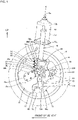
- FIG. 1 is a schematic view showing a wiring structure for in-wheel motor power lines according to a first embodiment of the present invention as viewed from inside in the lateral direction of a vehicle.
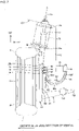
- FIG. 2 is a schematic view of the first embodiment as viewed from the front of the vehicle.
- FIG. 3 is a schematic view of the first embodiment as viewed from above.
- a road wheel W, an in-wheel motor drive device 10, and a suspension device 70 are disposed outside a vehicle body 101 (only an outer part in the lateral direction of the vehicle body is shown in FIG. 2 ) in the lateral direction of the vehicle.
- the road wheel W, the in-wheel motor drive device 10, and the suspension device 70 are disposed symmetrically on both sides of the vehicle body 101 in the lateral direction of the vehicle to form an electric vehicle.
- a tire T which is shown in phantom, is fitted on the road wheel W.
- the road wheel W and the tire T form a wheel.
- a rim portion Wr of the road wheel W defines an inner space region of the wheel.
- the in-wheel motor drive device 10 is disposed in the inner space region.
- the in-wheel motor drive device 10 is coupled to the road wheel W to drive the wheel.
- the suspension device 70 is a MacPherson strut suspension device and includes a lower arm 71 extending in the lateral direction of the vehicle and a strut 76 disposed above the lower arm 71 and extending in the vertical direction.
- the strut 76 is disposed inward of the road wheel W and the in-wheel motor drive device 10 in the lateral direction of the vehicle.
- the lower end of the strut 76 is coupled to the in-wheel motor drive device 10, and the upper end of the strut 76 is coupled to the vehicle body 101 at a position above the road wheel W.
- the strut 76, the upper part of the road wheel W, and the upper part of the in-wheel motor drive device 10 are accommodated in a wheel well 102 formed outside the vehicle body 101 in the lateral direction of the vehicle.
- the strut 76 is a suspension member containing a shock absorber 77 in its upper end region and capable of extending and contracting in the vertical direction.
- a coil spring 78 which is schematically shown in phantom, is disposed around the shock absorber 77 to absorb a vertical axial force that is applied to the strut 76.
- a damper that absorbs the axial force that is applied to the strut 76 is placed in the shock absorber 88.
- the lower arm 71 is a suspension member disposed below an axis O of the in-wheel motor drive device 10, and includes a lateral outer end 72 and lateral inner ends 73d, 73f.
- the lower arm 71 is coupled at the lateral outer end 72 to the in-wheel motor drive device 10 via a ball joint 60.
- the lower arm 71 is coupled at the lateral inner ends 73d, 73f to a vehicle body-side member, not shown.
- the lower arm 71 can swing in the vertical direction with the lateral inner ends 73d, 73f serving as a base end and the lateral outer end 72 as a free end.
- the "vehicle body-side member” refers to a member that is attached on the vehicle body side with respect to a member being described.
- a straight line connecting the lateral outer end 72 and an upper end 76a of the strut 76 extends in the vertical direction and forms a steering axis K.
- the steering axis K basically extends in the vertical direction, but may be slightly tilted in the lateral direction and/or the longitudinal direction of the vehicle.
- the lateral inner ends 73d, 73f are simply designated by the reference numeral 73 when they are not distinguished.
- a tie rod 80 is disposed above the lower arm 71.
- the tie rod 80 is disposed closer to the rear of the vehicle than the axis O is, and extends in the lateral direction.
- a lateral outer end of the tie rod 80 is rotatably coupled to the rear part of the in-wheel motor drive device 10.
- the rear part of the in-wheel motor drive device 10 means the rear part in the longitudinal direction of the vehicle.
- a lateral inner end of the tie rod 80 is coupled to a steering device, not shown. The steering device advances and withdraws the tie rod 80 in the lateral direction of the vehicle to steer the in-wheel motor drive device 10 and the road wheel W about the steering axis K.
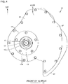
- FIG. 4 is a schematic view showing only the in-wheel motor drive device shown in FIGS. 1 to 3 , as viewed from outside in the lateral direction of the vehicle.
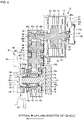
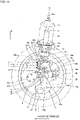
- FIG. 5 is a transverse section schematically showing the in-wheel motor drive device as viewed from outside in the lateral direction of the vehicle. In FIG. 5 , each gear in a speed reduction unit is shown by an addendum circle, and individual teeth are not shown.
- FIG. 6 is a developed section schematically showing the in-wheel motor drive device.
- the cutting plane in FIG. 6 is a developed plane connecting a plane including an axis M and an axis Nf shown in FIG.
- FIG. 7 is a longitudinal section showing the in-wheel motor drive device together with the wheel and the suspension device. For simplicity of the figure, the gears in the speed reduction unit are not shown in FIG. 7 .
- the in-wheel motor drive device 10 includes a wheel hub bearing unit 11 that, as shown in FIG. 6 , is coupled to the center of the road wheel W shown in phantom, a motor unit 21 that drives the road wheel W of the wheel, and a speed reduction unit 31 that reduces the speed of rotation of the motor unit to transmit the resultant rotation to the wheel hub bearing unit 11.
- the in-wheel motor drive device 10 is disposed in the wheel well, not shown, of the electric vehicle.
- the motor unit 21 and the speed reduction unit 31 are not disposed coaxially with the wheel hub bearing unit 11, namely are not disposed on the axis O of the wheel hub bearing unit 11.
- the motor unit 21 and the speed reduction unit 31 are offset from the axis O of the wheel hub bearing unit 11 as shown in FIG. 5 .
- the in-wheel motor drive device 10 can drive the electric vehicle at 0 to 180 km/h on public roads.
- the wheel hub bearing unit 11 has an outer ring 12 that serves as a hub ring coupled to the road wheel W as shown in FIG. 6 , an inner fixing member 13 inserted in a central hole of the outer ring 12, and a plurality of rolling elements 14 disposed in annular clearance between the outer ring 12 and the inner fixing member 13, and the wheel hub bearing unit 11 forms an axle.
- the inner fixing member 13 includes a non-rotary fixed shaft 15, a pair of inner races 16, a retaining nut 17, and a carrier 18.
- the fixed shaft 15 has a larger diameter in its root part 15r than in its tip end 15e.
- the inner races 16 are fitted on the fixed shaft 15 between the root part 15r and the tip end 15e.
- the retaining nut 17 is screwed on the tip end 15e of the fixed shaft 15 to fix the inner races 16 between the retaining nut 17 and the root part 15r.
- the fixed shaft 15 extends along the axis 0 and extends through a body casing 43 that serves as an outer shell of the speed reduction unit 31.
- the tip end 15e of the fixed shaft 15 extends through an opening 43p formed in a front part 43f of the body casing 43, and projects laterally outward beyond the front part 43f.
- the root part 15r of the fixed shaft 15 extends through an opening 43q, which is formed in a back part 43b of the body casing 43, from inward of the back part 43b in the lateral direction of the vehicle.
- the front part 43f and the back part 43b are wall portions that face each other at an interval in the direction of the axis O.
- the root part 15r is located inward of the back part 43b in the lateral direction of the vehicle.
- the carrier 18 is firmly attached to the root part 15r.
- the carrier 18 is located outside the body casing 43 and coupled to the suspension device 70 and the tie rod 80.
- the rolling elements 14 are arranged in two rows separated in the direction of the axis O.
- the outer peripheral surface of the inner race 16 located on one side in the direction of the axis O forms an inner raceway surface for the first row of the rolling elements 14 and faces a part of the inner peripheral surface of the outer ring 12 which is located on the one side in the direction of the axis O.
- the outer peripheral surface of the inner race 16 located on the other side in the direction of the axis O forms an inner raceway surface for the second row of the rolling elements 14 and faces a part of the inner peripheral surface of the outer ring 12 which is located on the other side in the direction of the axis O.
- the outer side in the lateral direction of the vehicle is sometimes referred to as the one side in the axial direction
- the inner side in the lateral direction of the vehicle is sometimes referred to as the other side in the axial direction.
- the lateral direction in the plane of paper of FIG. 6 corresponds to the lateral direction of the vehicle.
- the inner peripheral surface of the outer ring 12 forms an outer raceway surface for the rolling elements 14.
- the outer ring 12 has a flange portion 12f in its end located on the one side in the direction of the axis O.
- the flange portion 12f forms a coupling seat that is coaxially coupled to a brake disc BD and a spoke portion Ws of the road wheel W.
- the flange portion 12f of the outer ring 12 is coupled to the brake disc BD and the road wheel W, so that the outer ring 12 rotates with the road wheel W.
- the flange portion 12f may be projections projecting radially outward at intervals in the circumferential direction.
- the motor unit 21 includes a motor rotary shaft 22, a rotor 23, a stator 24, a motor casing 25, which are arranged in this order from the axis M of the motor unit 21 toward the outside in the radial direction.
- the motor unit 21 is an inner rotor, outer stator radial gap motor.
- the motor unit 21 may be of other types.
- the motor unit 21 may be, e.g., an axial gap motor.
- the axis M which is the center of rotation of the motor rotary shaft 22 and the rotor 23, extends parallel to the axis O of the wheel hub bearing unit 11. That is, the motor unit 21 is offset so as to be separated from the axis 0 of the wheel hub bearing unit 11. As shown in FIG. 6 , a large part of the motor unit 21 excluding the tip end of the motor rotary shaft 22 does not overlap the inner fixing member 13 in the axial direction.
- the motor casing 25 is tubular, is coupled at its end on the one side in the direction of the axis M to the back part 43b of the body casing 43, and is sealed at its end on the other side in the direction of the axis M to a lid-like motor casing cover 25v. Both ends of the motor rotary shaft 22 are rotatably supported by the back part 43b and the motor casing cover 25v via rolling bearings 27, 28.
- the motor unit 21 drives the outer ring 12 and the wheel.
- a power line terminal box 25b is disposed on the upper part of the in-wheel motor drive device 10.
- the power line terminal box 25b extends over the upper part of the motor casing 25 ( FIG. 6 ) and the upper part of the motor casing cover 25v ( FIG. 6 ) and has a plurality of power line connection portions 91.
- the power line terminal box 25b of the present embodiment has three power line connection portions 91 and receives three-phase AC power.
- One ends of power lines 93 are connected to power line connection portions 91.
- a core wire of the power lines 93 are connected to leads extending from a coil of the stator 24.
- a signal line terminal box 25c is formed on the central part of the motor casing cover 25v.
- the signal line terminal box 25c is separated from the power line terminal box 25b.
- the signal line terminal box 25c is disposed so as to cross the axis M as shown in FIG. 6 .
- the signal line terminal box 25c accommodates a rotation angle sensor 84.
- the rotation angle sensor 84 is placed on an axial end of the motor rotary shaft 22 and detects the rotation angle of the motor rotary shaft 22.
- the signal line terminal box 25c has a signal line connection portion 85.
- the signal line connection portion 85 has a wall portion of the signal line terminal box 25c, a through hole extending through the wall portion, and an internally threaded hole (not shown) formed in the wall portion near the through hole.
- a sleeve 86 and a signal line 87 are passed through the through hole.
- the sleeve 86 is a tubular member and is in close contact with the outer periphery of the signal line 87 to protect the signal line 87 and to seal annular clearance between the through hole and the signal line 87.
- the sleeve 86 has on its outer peripheral surface a tongue 86t projecting outward in the radial direction of the sleeve 86.
- a bolt not shown in FIG. 6 , is screwed into the tongue 86t and the internally threaded hole of the signal line connection portion 85, whereby the sleeve 86 is firmly attached to the signal line connection portion 85.
- the signal line 87 is formed by a plurality of core wires that are conductors and a covering that is made of an insulating material and covers the plurality of core wires so as to bundle them together.
- the signal line 87 is bendable.
- One end of the signal line 87 is connected to the signal line connection portion 85.
- the signal line 87 extends from the one end to the vehicle body 101 ( FIG. 2 ).
- Each power line connection portion 91 is configured similarly to the signal line connection portion 85, and has a wall portion of the power line terminal box 25b, a through hole extending through the wall portion, and an internally threaded hole (not shown) formed in the wall portion near the through hole.
- a sleeve 92 and the one end of the power line 93 are passed through the through hole.
- the sleeve 92 and the power line 93 extend toward the vehicle body 101 from the through hole of the power line connection portion 91.
- the power line 93 is passed through the sleeve 92 and extends toward the vehicle body 101 from the sleeve 92.
- Each sleeve 92 is a tubular member and is in close contact with the outer periphery of the power line 93 to protect the power line 93.
- Each sleeve 92 together with the one end of the power line 93 is inserted through the through hole of the power line connection portion 91 and is fixed therein to hold the one end of the power line 93 and to seal annular clearance between the power line 93 and the through hole.
- the sleeve 92 has on its outer peripheral surface a tongue 92t projecting outward in the radial direction of the sleeve 92.
- a bolt 91b shown in FIG. 1 is screwed into the tongue 92t and the internally threaded hole of the power line connection portion 91, whereby the sleeve 92 is firmly attached to the power line connection portion 91.
- the speed reduction unit 31 includes an input shaft 32, an input gear 33, an intermediate gear 34, an intermediate shaft 35, an intermediate gear 36, an intermediate gear 37, an intermediate shaft 38, an intermediate gear 39, an output gear 40, an output shaft 41, and the body casing 43.
- the input shaft 32 is a tubular member having a larger diameter than a tip end 22e of the motor rotary shaft 22 and extends along the axis M of the motor unit 21.
- the tip end 22e is placed in a central hole formed in an end of the input shaft 32 which is located on the other side in the direction of the axis M, so that the input shaft 32 is coaxially coupled to the motor rotary shaft 22. Both ends of the input shaft 32 are supported by the body casing 43 via rolling bearings 42a, 42b.
- the input gear 33 is an external gear having a smaller diameter than the motor unit 21 and is coaxially coupled to the input shaft 32. Specifically, the input gear 33 is integrally formed on the outer periphery of the middle part of the input shaft 32 in the direction of the axis M.
- the output shaft 41 is a tubular member having a larger diameter than a cylindrical portion of the outer ring 12 and extends along the axis O of the wheel hub bearing unit 11. An end of the outer ring 12 which is located on the other side in the direction of the axis O is placed in a central hole formed in an end of the output shaft 41 which is located on the one side in the direction of the axial O, so that the output shaft 41 is coaxially coupled to the outer ring 12.
- Rolling bearings 44, 46 are disposed on both ends of the output shaft 41 in the direction of the axis O.
- the end of the output shaft 41 which is located on the one side in the direction of the axis O is supported by the front part 43f of the body casing 43 via the rolling bearing 443.
- the end of the output shaft 41 which is located on the other side in the direction of the axis O is supported by the back part 43b of the body casing 43 via the rolling bearing 46.
- the output gear 40 is an external gear and is coaxially coupled to the output shaft 41.
- the output gear 40 is integrally formed on the outer periphery of the end of the output shaft 41 which is located on the other side in the direction of the axis O.
- the two intermediate shafts 35, 38 extend parallel to the input shaft 32 and the output shaft 41. That is, the speed reduction unit 31 is a parallel shaft gear reducer having four shafts.
- the axis O of the output shaft 41, the axis Nf of the intermediate shaft 35, the axis Nl of the intermediate shaft 38, and the axis M of the input shaft 32 extend parallel to each other, namely extend in the lateral direction of the vehicle.
- each shaft in the longitudinal direction of the vehicle will be described.
- the axis M of the input shaft 32 is located closer to the front of the vehicle than the axis O of the output shaft 41 is.
- the axis Nf of the intermediate shaft 35 is located closer to the front of the vehicle than the axis M of the input shaft 32 is.
- the axis Nl of the intermediate shaft 38 is located closer to the front of the vehicle than the axis O of the output shaft 41 is, and is located closer to the rear of the vehicle than the axis M of the input shaft 32 is.
- the axis M of the input shaft 32, the axis Nf of the intermediate shaft 35, the axis Nl of the intermediate shaft 38, and the axis O of the output shaft 41 may be located in this order from front to rear in the longitudinal direction of the vehicle. This order is also the order in which a driving force is transmitted.
- the vertical position of shaft will be described.
- the axis M of the input shaft 32 is located above the axis O of the output shaft 41.
- the axis Nf of the intermediate shaft 35 is located above the axis M of the input shaft 32.
- the axis Nl of the intermediate shaft 38 is located above the axis Nf of the intermediate shaft 35.
- the plurality of intermediate shafts 35, 38 need only be located above the input shaft 32 and the output shaft 41, and in a modification, not shown, the intermediate shaft 35 may be located above the intermediate shaft 38. Alternatively, in another modification, not shown, the output shaft 41 may be located above the input shaft 32.
- the intermediate gear 34 and the intermediate gear 36 are external gears and, as shown in FIG. 6 , are coaxially coupled to the middle part of the intermediate shaft 35 in the direction of the axis Nf. Both ends of the intermediate shaft 35 are supported by the body casing 43 via rolling bearings 45a, 45b.
- the intermediate gear 37 and the intermediate gear 39 are external gears, and are coaxially coupled the middle part of the intermediate shaft 38 in the direction of the axis Nl. Both ends of the intermediate shaft 38 are supported by the body casing 43 via rolling bearings 48a, 48b.
- the body casing 43 serves as an outer shell of the speed reduction unit 31 and the wheel hub bearing unit 11.
- the body casing 43 is tubular and surrounds the axes O, Nf, Nl, M as shown in FIG. 5 .
- the body casing 43 is accommodated in an inner space region of the wheel W.
- the inner space region of the wheel W is defined by the inner peripheral surface of the rim portion Wr and the spoke portion Ws coupled to an end of the rim portion Wr which is located on the one side in the direction of the axis O.
- the wheel hub bearing unit 11, the speed reduction unit 31, and a region of the motor unit 21 which is located on the one side in the axial direction is accommodated in the inner space region of the wheel W.
- a region of the motor unit 21 which is located on the other side in the axial direction protrudes beyond the wheel W toward the other side in the axial direction.
- the wheel W thus accommodates a large part of the in-wheel motor drive device 10.
- the body casing 43 has a portion 43c located directly below the axis O and a portion located away from the axis O of the output gear 40 in the longitudinal direction of the vehicle, specifically located directly below the axis M of the input gear 33, and projecting downward.
- This projecting portion forms an oil tank 47 and is located below the portion 43c located directly below the axis O.
- the oil tank 47 is defined by a substantially vertical rear wall portion 43t and a tilted front wall portion 43u and has a triangular shape that tapers downward, as viewed in the direction of the axis O.
- the rear wall portion 43t faces the ball joint 60 ( FIG. 7 ) in the longitudinal direction of the vehicle at an interval therebetween.
- the front wall portion 43u faces the front lower part of the rim portion Wr ( FIG. 7 ).
- the ball joint 60 includes a ball stud 61 and socket 62.
- the ball stud 61 extends in the vertical direction and has a ball portion 61b formed at its upper end and a stud portion 61s formed at its lower end.
- the socket 62 is formed in the inner fixed member 13 and slidably accommodates the ball portion 61b.
- the stud portion 61s extends through the lateral outer end 72 of the lower arm 71 in the vertical direction.
- the stud portion 61s has an externally threaded lower end, and a nut 72 is screwed on the lower end from below, whereby the stud portion 61s is firmly attached to the lower arm 71. As shown in FIG.
- the ball joint 60 is located above the lower end of the oil tank 47.
- the ball joint 60 and the oil tank 47 are disposed in the inner space region of the wheel W, the ball joint 60 is disposed directly below the axis O, and the oil tank 47 is separated from the ball joint 60 in the longitudinal direction of the vehicle.
- the ball joint 60 is disposed outward of the back part 43b in the lateral direction of the vehicle.
- the steering axis K extends vertically through the ball center of the ball portion 61b and crosses the fixed shaft 15 and a contact surface R of the tire T.
- the upper end of the carrier 18 is firmly attached to the lower end of the strut 76.
- the body casing 43 is tubular and, as shown in FIG. 6 , accommodates the input shaft 32, the input gear 33, the intermediate gear 34, the intermediate shaft 35, the intermediate gear 36, the intermediate gear 37, the intermediate shaft 38, the intermediate gear 39, the output gear 40, the output shaft 41, and the middle part of the wheel hub bearing unit 11 in the direction of the axis 0.
- Lubricating oil is sealed in the body casing 43, so that the speed reduction unit 31 is lubricated.
- the input gear 33, the intermediate gear 34, the intermediate gear 36, the intermediate gear 37, the intermediate gear 39, and the output gear 40 are helical gears.
- the body casing 43 has a tubular portion including the portion 43c located directly below the axis O and the oil tank 47 as shown in FIG. 5 , the substantially flat front part 43f that covers the one side in the axial direction of a tubular portion of the speed reduction unit 31 as shown in FIG. 6 , and the substantially flat back part 43b that covers the other side in the axial direction of the tubular portion of the speed reduction unit 31.
- the back part 43b is coupled to the motor casing 25.
- the back part 43b is also coupled to the fixed shaft 15.
- the front part 43f has the opening 43p through which the outer ring 12 extends.
- a sealing material 43s that seals annular clearance between the front part 43f and the outer ring 12 is placed in the opening 43p.
- the outer ring 12 that is a rotary element is thus accommodated, except for its end located on the one side in the direction of the axis O, in the body casing 43.
- a sealing material 43v is disposed on the inner peripheral surface of an end of the output shaft 41 which is located on the other side in the direction of the axis O. The sealing material 43v seals annular clearance between the output shaft 41 and the back part 43b.
- the input gear 33 having a smaller diameter and the intermediate gear 34 having a larger diameter are disposed on the other side in the axial direction (the motor unit 21 side) of the speed reduction unit 31 and mesh each other.
- the intermediate gear 36 having a smaller diameter and the intermediate gear 37 having a larger diameter are disposed on the one side in the axial direction (the flange portion 12f side) of the speed reduction unit 31 and mesh with each other.
- the intermediate gear 39 having a smaller diameter and the output gear 40 having a larger diameter are disposed on the other side in the axial direction of the speed reduction unit 31 and mesh with each other.
- the input gear 33, the plurality of intermediate gears 34, 36, 37, 39, and the output gear 40 thus mesh with each other, forming a drive transmission path from the input gear 33 through the intermediate gears 34, 36, 37, 39 to the output gear 40.
- the speed reduction unit 31 thus has a sufficient reduction ratio.
- the intermediate gear 34 is the first intermediate gear located on the input side of the drive transmission path.
- the intermediate gear 39 is the last intermediate gear located on the output side of the drive transmission path.
- the output shaft 41, the intermediate shaft 38, and the input shaft 32 are arranged in this order so as to be spaced apart from each other in the longitudinal direction of the vehicle.
- the intermediate shaft 35 and the intermediate shaft 38 are disposed above the input shaft 32 and the output shaft 41.
- the intermediate shafts can be disposed above the outer ring 12 that serves as a hub ring, so that space where the oil tank 47 is disposed can be provided below the outer ring 12 and space where the ball joint 60 ( FIG. 7 ) is accommodated can be provided directly below the outer ring 12.
- FIGS. 8 and 9 are schematic views showing the in-wheel motor drive device and the power lines.
- FIG. 8 shows the state as viewed from the rear of the vehicle
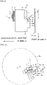
- FIG. 9 shows the state as viewed from above the vehicle in the direction of the steering axis.
- the three power lines 93 extend from the in-wheel motor drive device 10 to the vehicle body 101.
- the three power lines 93 supply three-phase AC power from the vehicle body 101 to the motor unit 21.
- Each power line 93 is formed by the core wire that are conductor and a shearth that is made of an insulating material and covers the entire circumference of the core wire.
- Each power line 93 is bendable.
- each power line 93 is held by the power line connection portion 91 and the sleeve 92 in such an attitude that the other end side of the power line 93 is tilted toward the rear of the vehicle and toward the inside in the lateral direction of the vehicle.
- the one end of each power line 93 is held tilted so as to intersect a base line extending in the longitudinal direction of the vehicle at an angle of ⁇ °.
- the angle ⁇ is a fixed value included in the range of 0° or more and 90° or less.
- ⁇ 0°
- the one end of each power line 93 extends parallel to the longitudinal direction of the vehicle.
- the angle ⁇ is more preferably a fixed value of 10° or more and 80° or less.
- the other end of each power line 93 is connected to an inverter 103 mounted on the vehicle body 101.
- the one ends of the power lines 93 are disposed so as to be aligned at intervals in the direction of the steering axis K as shown in FIG. 8 and to overlap each other as viewed in the direction of the steering axis K as shown in FIG. 9 .
- the one ends of the power lines 93 are disposed such that all of the power line connection portions 91 overlap each other as shown in FIG. 9 .
- Each power line 93 includes, between the one end and the other end thereof, three regions extending continuously. Of these three regions, the region located on the side connected to the in-wheel motor drive device 10 is referred to as the in-wheel motor drive device-side region 93d, the region located on the side connected to the vehicle body 101 is referred to as the vehicle body-side region 93f, and the region between the in-wheel motor drive device-side region 93d and the vehicle body-side region 93f is referred to as the intermediate region 93e.
- the in-wheel motor drive device-side region 93d extends in the vertical direction.
- the upper side of the in-wheel motor drive device-side region 93d is connected to the in-wheel motor drive device 10 side, and the lower side of the in-wheel motor drive device-side region 93d is connected to the intermediate region 93e.
- the vehicle body-side region 93f extends in the vertical direction.
- the lower side of the vehicle body-side region 93f is connected to the intermediate region 93e, and the upper side of the vehicle body-side region 93f is connected to the vehicle body 101 side.
- the intermediate region 93e is curved with its both sides located at a higher position and its intermediate part located at a lower position.
- each power line 93 which is connected to the power line connection portion 91 first extends horizontally toward the in-wheel motor drive device-side region 93d, but soon changes its direction so as to extend downward, and is connected to the upper side of the in-wheel motor drive device-side region 93d.
- the in-wheel motor drive device-side regions 93d are not held by a clamp member, and are suspended in the air and are disposed along the steering axis K.
- the expression "disposed along the steering axis K" means extending near the steering axis K so as to be substantially parallel to the steering axis K.
- the plurality of in-wheel motor drive device-side regions 93d are disposed in a region 79e with a predetermined radius that is twice the radius of the lower coil spring seat 79c about the steering axis K.
- the in-wheel motor drive device-side regions 93d thus extend in the vertical direction along the steering axis. At least one of the plurality of in-wheel motor drive device-side regions 93d overlaps a projected region 79d of the lower coil spring seat 79c as viewed in the direction of the steering axis K. It is preferable that the in-wheel motor drive device-side region 93d at least partially or completely overlap the projected region 79d of the lower coil spring seat 79c.
- the diameter of the projected region 79d substantially corresponds to that of the lower coil spring seat 79c.
- the plurality of power lines 93 are bundled by a clamp member 94 at a position located closer to the other ends of the power lines 93 than the vehicle body-side regions 93f are, and are thus held by the clamp member 94 so as to extend in the vertical direction.
- the vehicle body-side regions 93f are not held by a clamp member and are suspended in the air.
- the vehicle body-side regions 93f are located below the clamp member 94 and extend in the vertical direction.
- the clamp member 94 is firmly attached to the vehicle body 101 via a bracket 95.
- Disposing the bracket 95 inward of the wheel well 102 in the lateral direction of the vehicle allows the vehicle body-side regions 93f to be placed inward of a partition wall of the wheel well 102 in the lateral direction of the vehicle. This not only allows the power lines 93 to be placed so as to bypass the wheel well 102 but also allows the partition wall of the wheel well 102 to be placed closer to the in-wheel motor drive device 10 so that the size of the wheel well 102 can be reduced.
- the clamp member 94 overlaps at least one of the three power line connection portions 91 in the vertical direction.
- the set of the in-wheel motor drive device-side region 93d, the intermediate region 93e, and the vehicle body-side region 93f is thus held by the in-wheel motor drive device 10 and the vehicle body 101 so as to be curved in a U-shape with its lower side closed and its upper side open.
- the power line terminal box 25b and the three power line connection portions 91 are disposed closer to the front of the vehicle than the axis O is, and the power line connection portions 91 face toward the rear of the vehicle.
- This configuration allows the in-wheel motor drive device-side regions 93d to be placed near the steering axis K.
- the power line terminal box 25b and the three power line connection portions 91 may be disposed closer to the rear of the vehicle than the axis O is, and the power line connection portions 91 may face toward the front of the vehicle.
- the three power line connection portions 91 are located closer to the front of the vehicle than the axis O is, and the clamp member 94 is located closer to the rear of the vehicle than the axis 0 is.
- This configuration allows the in-wheel motor drive device-side regions 93d to be placed near the steering axis K.
- the three power line connection portions 91 may be disposed closer to the rear of the vehicle than the axis O is, and the clamp member 94 may be disposed closer to the front of the vehicle than the axis O is.
- the in-wheel motor drive device-side regions 93d need only be disposed so as to overlap the vehicle body-side regions 93f in the longitudinal direction of the vehicle when the vehicle is moving straight.
- the in-wheel motor drive device-side regions 93d are disposed at a relatively outer position in the lateral direction of the vehicle, and the vehicle body-side regions 93f are disposed at a relatively inner position in the lateral direction of the vehicle.
- the intermediate regions 83e thus extend in the lateral direction of the vehicle.
- Each intermediate region 93e is suspended on its both sides by the in-wheel motor drive device-side region 93d and the vehicle body-side region 93f.
- the intermediate regions 93e are not held by a clamp member and are suspended in the air.
- FIG. 10 is a schematic view showing only the power lines and the sleeves of the in-wheel motor drive device as viewed from above in the direction of the steering axis K.
- the power line connection portions 91 are shown in phantom in FIG. 10 .
- the sleeves 92 have the same size and shape and are disposed so as to partially overlap each other in the direction of the steering axis K. All of the three sleeves 92 overlap each other in the same overlap region L. Alternatively, although not shown in the figure, the sleeves 92 may be disposed so as to entirely overlap each other.
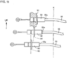
- FIG. 11 is a schematic view showing only the power lines and the sleeves of the in-wheel motor drive device as viewed in the lateral direction of the vehicle, and corresponds to FIG. 10 .
- the power line connection portions 91 is shown by solid line and the other power line connection portions 91 are shown in phantom in FIG. 11 .
- the distance from the steering axis K to each sleeve 92 is substantially the same. Steering stress that is applied to each power line 93 can therefore be made substantially the same.
- the power line 93 includes the in-wheel motor drive device-side region 93d extending in the vertical direction along the steering axis K.
- This configuration allows the power lines 93 to be disposed closer to the steering axis K. Accordingly, the power lines 93 are not repeatedly bent and extended even when the in-wheel motor drive device 10 is steered together with the wheel. Bending fatigue therefore does not accumulate in the power lines 93, and the life of the power lines 93 can be extended.
- the power line 93 further includes the intermediate region 93e and the vehicle body-side region 93f between the in-wheel motor drive device-side region 93d and the other end (the end on the vehicle body 101 side).
- the upper side of the in-wheel motor drive device-side region 93d is connected to the in-wheel motor drive device 10 side, and the lower side of the in-wheel motor drive device-side region 93d is connected to the intermediate region 93e.
- the vehicle body-side region 93f extends in the vertical direction.
- the lower side of the vehicle body-side region 93f is connected to the intermediate region 93e, and the upper side of the vehicle body-side region 93f is connected to the vehicle body 101 side.
- the intermediate region 93e is curved with its both sides located at a higher position and its intermediate part located at a lower position. Accordingly, when the in-wheel motor drive device 10 is steered, the power lines 93 are hardly displaced, the curvature of the intermediate regions 93e hardly changes, and the in-wheel motor drive device-side regions 93d are merely twisted. The power lines 93 therefore will not be repeatedly bent and extended, and bending fatigue will not accumulate in the power lines 93. Even if the strut 76 extends and contracts and the in-wheel motor drive device 10 also bounces in the vertical direction, the curvature of the intermediate regions 93e changes only slightly, and the power lines 93 will not be repeatedly bent and extended.
- the twisting of the in-wheel motor drive device-side regions 93d can be substantially eliminated particularly in the case where the steering axis K crosses at least one of the plurality of in-wheel motor drive device-side regions 93d.
- the vehicle body-side regions extend in the vertical direction, and the upper or lower sides of the vehicle body-side regions are connected to the vehicle body side.
- This configuration allows the power lines to be placed such that a part of each power line bypasses the wheel well of the vehicle body, such as, e.g., placing the power lines such that the vehicle body-side regions extend along the back surface (the surface facing toward the inside of the vehicle body) of the wheel well partition wall that separates the wheel well from the internal space of the vehicle. Accordingly, there is no need to form a through hole in the wheel well partition wall and pass the power lines through the through hole, and there is also no need to increase the size of the wheel well. Accordingly, rigidity and strength of the wheel well will not be reduced, and the internal space of the vehicle body will not be sacrificed.
- the power lines 93 are hardly displaced, the curvature of the intermediate regions 93e hardly changes, and the in-wheel motor drive device-side regions 93d are merely twisted.
- the power lines 93 therefore will not be repeatedly bent and extended, and bending fatigue will not accumulate in the power lines 93.
- the strut 76 extends and contracts and the in-wheel motor drive device 10 also bounces in the vertical direction, the curvature of the intermediate regions 93e changes only slightly, and the power lines 93 will not be repeatedly bent and extended.
- the vehicle body-side regions 93f extend in the vertical direction and the upper sides of the vehicle body-side regions 93f are connected to the vehicle body 101 side.
- This configuration allows the power lines 93 to be disposed so as to bypass the wheel well 102. Accordingly, there is no need to form a through hole in the partition wall of the wheel well 102 and pass the power lines through the through hole, and rigidity and strength of the wheel well 102 will therefore not be reduced.
- the above configuration also allows the partition wall of the wheel well 102 to be placed at an outer position in the lateral direction of the vehicle than in conventional examples so that the partition wall of the wheel well 102 can be located closer to the in-wheel motor drive device 10. Accordingly, the size of the wheel well 102 can be reduced and the size of the internal space of the vehicle can be increased as compared to the conventional examples.
- the one ends of the power lines 93 which extend from the power line connection portions 91 are disposed so as to at least partially overlap each other as viewed in the direction of the steering axis K.
- This configuration allows the one end of every power line 93 to be disposed at substantially the same distance from the steering axis K. Accordingly, steering stress will not concentrate on a specific power line 93, and all of the power lines 93 can have substantially the same length of life.
- the in-wheel motor drive device-side region 93d, the intermediate region 93e, and the vehicle body-side region 93f is not held by anything, this region can be bent or twisted as necessary. Steering stress therefore will not concentrate on a specific part of this region, and the life of the power lines 93 can be extended.
- the power lines 93 are held, at a position located closer to the other side (the vehicle body 101 side) than the vehicle body-side regions 93f are, by the clamp member 94 provided on the vehicle body 101.
- the vehicle body-side regions 93f can thus be made to extend in the vertical direction.
- the intermediate regions 93e extend in the lateral direction of the vehicle. This configuration allows the in-wheel motor drive device-side regions 93d located on the one end side to be separated in the lateral direction of the vehicle from the vehicle body-side regions 93f located on the other end side.
- each power line 93 extending from the power line connection portion 91 is passed through the sleeve 92.
- Each sleeve 92 together with the one end of the power line 93 is inserted through the through hole of the power line connection portion 91 and is fixed therein to hold the one end of the power line 93 and to seal the annular clearance between the power line 93 and the through hole.
- the power line terminal box 25b can thus be made watertight.
- the sleeves 92 are disposed so as to at least partially overlap each other as viewed in the direction of the steering axis K. This configuration allows the one end of every power line 93 to be disposed at substantially the same distance from the steering axis K. Accordingly, steering stress will not concentrate on a specific power line 93, and the life of each power line 93 can be extended.
- the strut 76 includes the coil spring 78 and the pair of coil spring seats 79b, 79c and can extend and contract in the direction of the steering axis K.
- the one ends of the power lines 93 which are connected to the power line connection portions 91 are disposed so as to overlap the lower coil spring seat 79c as viewed in the direction of the steering axis K.
- the one ends 93a of the power lines 93 are included in the projected region 79d of the lower coil spring seat 79c which extends parallel to the steering axis K.
- FIG. 8 the one ends 93a of the power lines 93 are included in the projected region 79d of the lower coil spring seat 79c which extends parallel to the steering axis K.
- the one ends of the power lines 93 which are connected to the power line connection portions 91 thus overlap the lower coil spring seat 79c as viewed in the direction of the steering axis K.
- the one ends 93a of the power lines 93 are disposed near the steering axis K, and the in-wheel motor drive device-side regions 93d are also disposed near the steering axis K, so that the extent to which the in-wheel motor drive device-side regions 93d are twisted when the in-wheel motor drive device 10 is steered can be reduced.
- FIG. 12 is a schematic view showing a wiring structure for in-wheel motor power lines according to the second embodiment of the present invention as viewed from inside in the lateral direction of the vehicle.
- FIG. 13 is a schematic view of the second embodiment as viewed from the front of the vehicle.
- FIG. 14 is a schematic view of the second embodiment as viewed from above the vehicle.
- the same configurations as those of the above embodiment are denoted with the same reference characters and description thereof will be omitted. Configurations different from those of the above embodiment will be described.
- each power line 93 is connected at its one end to the power line connection portion 91 and extends downward from the one end to form the in-wheel motor drive device-side region 93d.
- the power lines 93 are placed so as to extend upward from the power line connection portions 91 and to bent in the opposite direction under the lower coil spring seat 79c to extend downward.
- Each power line 93 further includes a wheel vicinity region 93b between the one end on the power line connection portion 91 side of the power line 93 and the in-wheel motor drive device-side region 93d.
- the wheel vicinity region 93b extends in the vertical direction and is placed near the upper part of the tire T.
- the lower side of the wheel vicinity region 93b is connected to the power line connection portion 91 side, and the upper side of the wheel vicinity region 93 is connected to the in-wheel motor drive device-side region 93d.
- connection portion 93c between the wheel vicinity region 93b and the in-wheel motor drive device-side region 93d is placed around the strut 76 so as to be located next to the lower coil spring seat 79c.
- the connection point 93c is thus smoothly bent with a radius of curvature larger than the radius of the strut 76.
- connection portions 93c Clearance between the power lines 93 and the wheel is the smallest in the connection portions 93c.
- a cover 97 is therefore interposed between the tread of the tire T and the connection portions 93c.
- the cover 97 is firmly attached to the outer peripheral surface of the strut 76 to support the connection portions 93c from below.
- the wheel vicinity regions 93b and the in-wheel motor drive device-side regions 93d extend along the strut 76 and is held by a clamp member 96 that is firmly attached to the outer peripheral surface of the strut 76. Accordingly, at least in the region from the clamp member 96 to the connection portions 93c, the wheel vicinity regions 93b and the in-wheel motor drive device-side regions 93d will not be bent so as to be separated from the strut 76.
- the clamp member 96 is intended to bundle the plurality of power lines 93 and place them on an inner surface of the strut 76 in the lateral direction of the vehicle, and is not intended to restrict twisting of the power lines 93.
- the in-wheel motor drive device-side regions 93d of the power lines 93 can be individually twisted.
- the in-wheel motor drive device-side regions 93d are placed outward of the wheel vicinity regions 93b in the lateral direction of the vehicle and extend downward beyond the wheel vicinity regions 93b.
- each power line 93 further includes the wheel vicinity region 93b between the one end of the power line 93 which is connected to the power line connection portion 91 and the in-wheel motor drive device-side region 93d.
- the wheel vicinity region 93b extends in the vertical direction, the lower side of the wheel vicinity region 93b is connected to the power line connection portion 91 side, and the upper side of the wheel vicinity region 93b is connected to the in-wheel motor drive device-side region 93d.
- This configuration allows the in-wheel motor drive device-side regions 93d to have a greater length than in the first embodiment, whereby the extent to which each in-wheel motor drive device-side region 93b is twisted per unit length when the in-wheel motor drive device 10 is steered can be reduced.
- the wheel vicinity regions 93b are held by the clamp member 96 provided on the suspension device 70. This configuration allows the wheel vicinity regions 93b to be held so as to extend in the vertical direction.
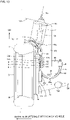
- FIG. 15 is a schematic diagram showing a wiring structure for in-wheel motor power lines according to the third embodiment of the present invention as viewed from the front of the vehicle.
- the same configurations as those of the above embodiments are denoted with the same reference characters and description thereof will be omitted. Configurations different from those of the above embodiments will be described.
- the one end of each power line 93 is connected to the power line connection portion 91 of the in-wheel motor drive device 10, and the other end of each power line 93 extends to the wheel body 101.
- An in-wheel motor drive device-side region 93h, an intermediate region 93i, and a vehicle-side region 93j extend continuously in this order from the one end to the other end of each power line 93.
- the three in-wheel motor drive device-side regions 93h extend upward from the power line connection portions 91 and are bundled by the clamp member 96 attached to a lower end region of the strut 76.
- the in-wheel motor drive device-side regions 93h extend from the clamp member 96 upward along the strut 76, pass by the lower coil spring seat 79c and by the upper coil spring seat 79b, and are passed through a through hole 104 formed in the partition wall of the upper part of the wheel well 102.
- the three vehicle body-side regions 93j are disposed in the vehicle body 101 and extend in the vertical direction.
- the plurality of power lines 93 are bundled by the clamp member 94 at a position located closer to the other ends of the power lines 93 than the vehicle body-side regions 93j are, and are thus held by the clamp member 94 so as to extend in the vertical direction.
- the vehicle body-side regions 93j are therefore not held by a clamp member and are suspended in the air.
- the vehicle body-side regions 93j are located above the clamp member 94 and extend in the vertical direction.
- the three intermediate regions 93i are located above the upper coil spring seat 79b.
- the three intermediate regions 93i are disposed in the vehicle body 101 and extend in the lateral direction of the vehicle. More specifically, each intermediate region 93i is curved with its both sides located at a lower position and its intermediate part located at a higher position.
- the plurality of intermediate regions 93i are not held by a clamp member and are suspended in the air above the through hole 104.
- the set of the in-wheel motor drive device-side region 93h, the intermediate region 93i, and the vehicle body-side region 93j is thus held by the strut 76 and the vehicle body 101 so as to be curved in an inverted U-shape with its upper side closed and its lower side open.
- each power line 93 further includes the intermediate region 93i and the vehicle body-side region 93j between the in-wheel motor drive device-side region 93h and the other side of the power line 93 which is the vehicle body 101 side.
- the lower side of the in-wheel motor drive device-side region 93h is connected to the in-wheel motor drive device 10 side, and the upper side of the in-wheel motor drive device-side region 93h is connected to the intermediate region 93i.
- the vehicle body-side region 93j extends in the vertical direction.
- the upper side of the vehicle body-side region 93j is connected to the intermediate region 93i, and the lower side of the vehicle body-side region 93j is connected to the vehicle body 101 side.
- the intermediate region 93i is curved with its both sides located at a lower position and its intermediate part located at a higher position. According to the present embodiment, curvature of the intermediate regions 93i hardly changes even if the in-wheel motor drive device 10 is steered.
- the vehicle body-side regions 93j extend in the vertical direction, and the lower side of each vehicle body-side region 93j is connected to the vehicle body 101 side.
- This configuration allows the power lines to be placed such that a part of each power line bypasses the wheel well of the vehicle body, such as, e.g., placing the power lines such that the vehicle body-side regions 93j extend along the back surface (the surface facing toward the inside of the vehicle body) of the wheel well partition wall that separates the wheel well 102 from the internal space of the vehicle.
- the wheel well partition wall can be placed at an outer position in the lateral direction of the vehicle than in the conventional examples, and the size of the wheel well 102 can be reduced.
- the in-wheel motor drive device of the present invention is advantageously used in electric and hybrid vehicles.
Landscapes
- Engineering & Computer Science (AREA)
- Mechanical Engineering (AREA)
- Chemical & Material Sciences (AREA)
- Combustion & Propulsion (AREA)
- Transportation (AREA)
- Arrangement Or Mounting Of Propulsion Units For Vehicles (AREA)
Description
- The present invention relates to power lines that extend from an in-wheel motor drive device to a vehicle body to supply electric power from the vehicle body to the in-wheel motor drive device.
- A technique of mounting an in-wheel motor inside a wheel of an electric vehicle to drive the wheel by the in-wheel motor is conventionally known in the art. In such electric vehicles, it is not necessary to mount an engine and a motor on a vehicle body, which is advantageous in that the vehicle body can have larger internal space such as passenger space and cargo space. The in-wheel motor is coupled to the vehicle body of the electric vehicle via a suspension device. A control unit, a battery, and an inverter for the in-wheel motor are mounted on the vehicle body. The in-wheel motor coupled to an unsprung part (the wheel side) of the suspension device and the inverter mounted on a sprung part (the vehicle body side) of the suspension device are connected by power lines. For example, power lines as described in
Japanese Patent No. 4,628,136 Japanese Unexamined Patent Application Publication No. 2006-240430 - Other wiring structures for an in-wheel motor power line are known from
JP 2013 147084 A JP 2016 032962 A JP 2014 189107 A - However, such conventional power lines have the following problems. When the in-wheel motor is steered, the power lines connected to the in-wheel motor are displaced about a steering axis. The power lines are thick and hard to bend. However, the power lines are bent and extended every time the in-wheel motor is steered to the right or left from the direction in which the vehicle is moving straight, or the power lines are repeatedly bent in the lateral direction at the same position so as to repeatedly alternately have a mountain fold and a valley fold. If the power lines are repeatedly bent and extended at the same position over a long period, bending fatigue accumulates, causing degradation.
- Conventionally, a wheel, an in-wheel motor drive device, a suspension device, and power lines are disposed in a wheel well of a vehicle body. Accordingly, if longer power lines are used to reduce bending and extension of the power lines, a larger wheel well is required, which results in smaller internal space of the vehicle body such as passenger space and cargo space. This degrades loading capability of electric vehicles.
- The power lines described in the patent literatures are placed so as to extend substantially horizontally from the in-wheel motor toward the inside in the lateral direction of the vehicle, or are placed so as to extend upward from the in-wheel motor toward the inside in the lateral direction of the vehicle. Accordingly, a through hole is formed in the wheel well of the vehicle body and the power lines extending in the lateral direction of the vehicle are passed through the through hole. Forming such a through hole reduces rigidity and strength of the wheel well and a vehicle body structural material.
- In view of the above circumstances, the present invention relates to in-wheel motor drive devices for steered wheels and it is an object of the present invention to provide a technique of reducing bending and extension of power lines during steering. It is another object of the present invention to provide the layout of in-wheel motor power lines which does not sacrifice internal space of a vehicle body and that does not require formation of a through hole in a wheel well and a vehicle body structural material.
- In order to achieve the above objects, wiring structures for an in-wheel motor power line according to the present invention as defined in
independent claim 1 and in independent claim 2 are proposed. - According to the present invention, the in-wheel motor drive device-side region of the power line is placed near the steering axis. Accordingly, when the in-wheel motor drive device is steered, the power line is hardly displaced, and the in-wheel motor drive device-side region that is long in the vertical direction is merely twisted. The power line therefore will not be repeatedly bent and extended, and bending fatigue will not accumulate in the power line. Displacement and bending and extension of the power line associated with steering can therefore be reduced as compared to conventional examples. The "in-wheel motor drive device-side region extending in the vertical direction along the steering axis" includes the case where a part of the power line extends so as to overlap the steering axis and the case where a part of the power line is located near the steering axis and extends substantially parallel to the steering axis. For example, "near the steering axis" is a region with a predetermined radius about the steering axis. The region with a predetermined radius is not particularly limited. However, for example, the region with a predetermined radius is determined based on a coil spring seat of a shock absorber disposed along the steering axis. Namely, the region with a predetermined radius is a region with a radius that is twice that of the coil spring seat. In the case where there are a plurality of power lines, at least one of the power lines need only extend in the vertical direction along the steering axis. However, it is preferable that the plurality of power lines be disposed so as to extend in the vertical direction along the steering axis.
- According to the first alternative of the present invention, the power line includes an intermediate region and a vehicle body-side region between the in-wheel motor drive device-side region and the other end, an upper side of the in-wheel motor drive device-side region is connected to the in-wheel motor drive device side, and a lower side of the in-wheel motor drive device-side region is connected to the intermediate region, the vehicle body-side region extends in the substantially vertical direction, a lower side of the vehicle body-side region is connected to the intermediate region, an upper side of the vehicle body-side region is connected to the vehicle body side, and the intermediate region is curved with its both sides located at a higher position and its intermediate part located at a lower position. According to the second alternative of the present invention, the power line includes an intermediate region and a vehicle body-side region between the in-wheel motor drive device-side region and the other end, a lower side of the in-wheel motor drive device-side region is connected to the in-wheel motor drive device side, an upper side of the in-wheel motor drive device-side region is connected to the intermediate region, the vehicle body-side region extends in the substantially vertical direction, an upper side of the vehicle body-side region is connected to the intermediate region, a lower side of the vehicle body-side region is connected to the vehicle body side, and the intermediate region is curved with its both sides located at a lower position and its intermediate part located at a higher position. According to the present invention, curvature of the intermediate region hardly changes. According to the present invention, the vehicle body-side region extends in the substantially vertical direction, and the upper or lower side of the vehicle body-side region is connected to the vehicle body side. This configuration allows the power line to be placed such that a part of the power line bypasses a wheel well of the vehicle body, such as, e.g., placing the power line such that the vehicle body-side region extends along the back surface (the surface facing toward the inside of the vehicle body) of a wheel well partition wall that separates the wheel well from the internal space of the vehicle. Accordingly, there is no need to form a through hole in the wheel well partition wall and pass the power line through the through hole, and there is also no need to increase the size of the wheel well. Rigidity and strength of the wheel well therefore will not be reduced, and the internal space of the vehicle body will not be sacrificed.
- In a preferred embodiment of the present invention, the wiring structure for the in-wheel motor power line includes: a plurality of the power lines, and the one ends of the power lines which are connected to the power line connection portions are disposed so as to at least partially overlap each other as viewed in a direction of the steering axis. According to this embodiment, the one ends of the power lines which extend from the power line connection portions are disposed so as to at least partially overlap each other as viewed in the direction of the steering axis. This configuration allows the one ends of the plurality of power lines to be disposed at substantially the same distance from the steering axis. Accordingly, steering stress will not concentrate on a specific power line, and all of the power lines can have substantially the same length of life. The overall life of the power lines can thus be extended. The one ends of all of the power lines may overlap each other in the same overlap region, or the one ends of two or more of the power lines may overlap each other in the same overlap region. Alternatively, the one ends of at least two adjacent ones of the power lines may overlap each other. In another embodiment, the plurality of power lines may be bundled and covered by a common sheath to form a single cable.
- The power line of the present invention may have its one end connected to the power line connection portion and extend downward from the one end to form the in-wheel motor drive device-side region. Alternatively, in a preferred embodiment of the present invention, the power line further includes a wheel vicinity region between the one end and the in-wheel motor drive device-side region, the wheel vicinity region extends in the vertical direction, a lower side of the wheel vicinity region is connected to the power line connection portion side, and an upper side of the wheel vicinity region is connected to the in-wheel motor drive device-side region. According to this embodiment, the in-wheel motor drive device-side region has a greater length as compared to the power line extending downward from the one end to form the in-wheel motor drive device-side region. The extent to which the in-wheel motor drive device-side region is twisted per unit length when the in-wheel motor drive device is steered can thus be reduced.
- In a preferred embodiment of the present invention, the wheel vicinity region is held by a clamp member provided on the suspension device. According to this embodiment, the wheel vicinity region can be held so as to extend in the vertical direction.
- In an embodiment of the present invention, at least one of the in-wheel motor drive device-side region, the intermediate region, and the vehicle body-side region is not held by anything. According to this embodiment, since at least one of the regions is not held by anything, this region can be bent or twisted as necessary. Steering stress therefore will not concentrate on a specific part of this region, and the life of the power line can be extended. In another embodiment, at least one of the in-wheel motor drive device-side region, the intermediate region, and the vehicle body-side region may be held by a clamp member or contact another member so that bending of that region is restricted.
- In an embodiment of the present invention, the power line is held, at a position located closer to the other end than the vehicle body-side region is, by a clamp member provided on the vehicle body. According to this embodiment, the power line on the in-wheel motor drive device side is suspended from the clamp member, whereby the vehicle body-side region can be made to extend in the vertical direction. In another embodiment, the vehicle body-side region may be held by a clamp member so as to extend in the vertical direction.
- In an embodiment of the present invention, the intermediate region of the power line extends in a lateral direction of a vehicle. According to this embodiment, the in-wheel motor drive device-side region located on the one end side can be separated in the lateral direction of the vehicle from the vehicle body-side region located on the other end side. This avoids interference of the in-wheel motor drive device with the vehicle body-side region when the in-wheel motor drive device is steered. In a more preferred embodiment, the in-wheel motor drive device-side region need only be disposed so as to overlap the vehicle body-side region in a longitudinal direction of the vehicle when the vehicle is moving straight, namely when the in-wheel motor drive device is not steered to the right or left. Alternatively, the power line may be placed such that the in-wheel motor drive device-side region is separated from the vehicle body-side region in the longitudinal direction of the vehicle and the intermediate region extends obliquely as viewed from above.
- It is desirable that the one end of the power line be passed through a sleeve near the power line connection portion and be protected by the sleeve. In an embodiment of the present invention, the one end of the power line which extends from the power line connection portion is passed through a sleeve, each of the sleeves together with the one end of the power line is inserted through a through hole of the power line connection portion and is fixed therein to hold the one end of the power line and to seal annular clearance between the power line and the through hole, and the sleeves are disposed so as to at least partially overlap each other as viewed in the direction of the steering axis. According to this embodiment, the one ends of the power lines which extend from the power line connection portions can be disposed so as to at least partially overlap each other as viewed in the direction of the steering axis. This configuration allows the one ends of the plurality of power lines to be disposed at substantially the same distance from the steering axis. Accordingly, steering stress will not concentrate on a specific power line, and all of the power lines can have substantially the same length of life. The overall life of the power lines can thus be extended. All of the sleeves may overlap each other in the same overlap region, or at least two of the sleeves may overlap each other in the same overlap region. Alternatively, at least two adjacent ones of the sleeves may overlap each other.
- The suspension device of the present invention may be a double wishbone suspension device or may be other types of suspension device. Although not particularly limited, in an embodiment of the present invention, the suspension device includes a strut coupled to an upper part of the in-wheel motor drive device and a lower arm coupled to a lower part of the in-wheel motor drive device, the strut includes a coil spring and a pair of coil spring seats that are disposed on upper and lower ends of the coil spring to hold the coil spring therebetween, and is capable of extending and contracting in the direction of the steering axis, and the one ends of the power lines which are connected to the power line connection portions are disposed so as to overlap the coil spring seat as viewed in the direction of the steering axis. According to this embodiment, the one ends of the power lines are disposed near the steering axis, and the extent to which the power lines are twisted when the in-wheel motor drive device is steered can be reduced. The in-wheel motor drive device-side regions are also disposed near the steering angle. The closer the in-wheel motor drive device-side regions are to the steering axis K, the more the extent to which the in-wheel motor drive device-side regions are twisted when the in-wheel motor drive device is steered can be reduced.
- The present invention also concerns an in-wheel motor drive device including an in-wheel motor power line and capable of being steered. That is, the present invention also relates to an in-wheel motor drive device as defined in
claim 11. - According to the present invention, the in-wheel motor drive device-side region of the power line can be placed near the steering axis, and displacement and bending and extension of the power line associated with steering can be reduced as compared to the conventional examples. According to the present invention, when the in-wheel motor drive device is steered, the power line is hardly displaced, and curvature of the intermediate region hardly changes, and the in-wheel motor drive device-side region that is long in the vertical direction is merely twisted. The power line therefore will not be repeatedly bent and extended, and bending fatigue will not accumulate in the power line. According to the present invention, the vehicle body-side region extends in the vertical direction, and the upper side of the vehicle body-side region is connected to the vehicle body side. The power line can therefore be placed so as to bypass the wheel well of the vehicle body. Accordingly, there is no need to form a through hole in the wheel well and pass the power line through the through hole, and there is also no need to increase the size of the wheel well. Rigidity and strength of the wheel well therefore will not be reduced, and the internal space of the vehicle body will not be sacrificed.
- As described above, according to the present invention, a preferred power line layout can be provided for a power line of an in-wheel motor drive device. The power line will not be repeatedly bent and extended when the in-wheel motor drive device is steered, and durability of the power line is improved. A wheel well of a vehicle body can be reduced in size, and the internal space of a vehicle body can be increased. Moreover, steering stress will not concentrate on a specific one of a plurality of the power lines, whereby the life of every power line can be extended.
-
-
FIG. 1 is a schematic view showing a wiring structure for in-wheel motor power lines according to a first embodiment of the present invention as viewed from inside in the lateral direction of a vehicle. -
FIG. 2 is a schematic view of the first embodiment as viewed from the front of the vehicle. -
FIG. 3 is a schematic view of the first embodiment as viewed from above the vehicle. -
FIG. 4 is a schematic view showing only an in-wheel motor drive device, as viewed from outside in the lateral direction of the vehicle. -
FIG. 5 is a transverse section of the in-wheel motor drive device. -
FIG. 6 is a developed section of the in-wheel motor drive device. -
FIG. 7 is a longitudinal section schematically showing the in-wheel motor drive device and a suspension device. -
FIG. 8 is a schematic view showing the in-wheel motor drive device and the power lines as viewed from the rear of the vehicle. -
FIG. 9 is a schematic view showing the in-wheel motor drive device and the power lines as viewed from above the vehicle in the direction of a steering axis. -
FIG. 10 is a schematic view showing only the power lines and sleeves of the in-wheel motor drive device as viewed from above in the direction of the steering axis. -
FIG. 11 is a schematic view showing only the power lines and the sleeves of the in-wheel motor drive device as viewed in the lateral direction of the vehicle. -
FIG. 12 is a schematic view showing a wiring structure for in-wheel motor power lines according to a second embodiment of the present invention as viewed from inside in the lateral direction of a vehicle. -
FIG. 13 is a schematic view of the second embodiment as viewed from the front of the vehicle. -
FIG. 14 is a schematic view of the second embodiment as viewed from above the vehicle. -
FIG. 15 is a schematic view showing a wiring structure for in-wheel motor power lines according to a third embodiment of the present invention as viewed from the front of a vehicle. - Embodiments of the present invention will be described in detail below with reference to the accompanying drawings.
FIG. 1 is a schematic view showing a wiring structure for in-wheel motor power lines according to a first embodiment of the present invention as viewed from inside in the lateral direction of a vehicle.FIG. 2 is a schematic view of the first embodiment as viewed from the front of the vehicle.FIG. 3 is a schematic view of the first embodiment as viewed from above. In the first embodiment, a road wheel W, an in-wheelmotor drive device 10, and asuspension device 70 are disposed outside a vehicle body 101 (only an outer part in the lateral direction of the vehicle body is shown inFIG. 2 ) in the lateral direction of the vehicle. The road wheel W, the in-wheelmotor drive device 10, and thesuspension device 70 are disposed symmetrically on both sides of thevehicle body 101 in the lateral direction of the vehicle to form an electric vehicle. - A tire T, which is shown in phantom, is fitted on the road wheel W. The road wheel W and the tire T form a wheel. A rim portion Wr of the road wheel W defines an inner space region of the wheel. The in-wheel
motor drive device 10 is disposed in the inner space region. The in-wheelmotor drive device 10 is coupled to the road wheel W to drive the wheel. - The
suspension device 70 is a MacPherson strut suspension device and includes alower arm 71 extending in the lateral direction of the vehicle and astrut 76 disposed above thelower arm 71 and extending in the vertical direction. Thestrut 76 is disposed inward of the road wheel W and the in-wheelmotor drive device 10 in the lateral direction of the vehicle. The lower end of thestrut 76 is coupled to the in-wheelmotor drive device 10, and the upper end of thestrut 76 is coupled to thevehicle body 101 at a position above the road wheel W. Thestrut 76, the upper part of the road wheel W, and the upper part of the in-wheelmotor drive device 10 are accommodated in a wheel well 102 formed outside thevehicle body 101 in the lateral direction of the vehicle. - The
strut 76 is a suspension member containing ashock absorber 77 in its upper end region and capable of extending and contracting in the vertical direction. Acoil spring 78, which is schematically shown in phantom, is disposed around theshock absorber 77 to absorb a vertical axial force that is applied to thestrut 76. A pair ofcoil spring seats coil spring 78 to hold thecoil spring 78 therebetween, are placed in the upper end and the middle part of thestrut 76. A damper that absorbs the axial force that is applied to thestrut 76 is placed in the shock absorber 88. - The
lower arm 71 is a suspension member disposed below an axis O of the in-wheelmotor drive device 10, and includes a lateralouter end 72 and lateral inner ends 73d, 73f. Thelower arm 71 is coupled at the lateralouter end 72 to the in-wheelmotor drive device 10 via a ball joint 60. Thelower arm 71 is coupled at the lateral inner ends 73d, 73f to a vehicle body-side member, not shown. Thelower arm 71 can swing in the vertical direction with the lateral inner ends 73d, 73f serving as a base end and the lateralouter end 72 as a free end. The "vehicle body-side member" refers to a member that is attached on the vehicle body side with respect to a member being described. A straight line connecting the lateralouter end 72 and anupper end 76a of thestrut 76 extends in the vertical direction and forms a steering axis K. The steering axis K basically extends in the vertical direction, but may be slightly tilted in the lateral direction and/or the longitudinal direction of the vehicle. In the figures, the lateral inner ends 73d, 73f are simply designated by thereference numeral 73 when they are not distinguished. - A
tie rod 80 is disposed above thelower arm 71. Thetie rod 80 is disposed closer to the rear of the vehicle than the axis O is, and extends in the lateral direction. A lateral outer end of thetie rod 80 is rotatably coupled to the rear part of the in-wheelmotor drive device 10. The rear part of the in-wheelmotor drive device 10 means the rear part in the longitudinal direction of the vehicle. A lateral inner end of thetie rod 80 is coupled to a steering device, not shown. The steering device advances and withdraws thetie rod 80 in the lateral direction of the vehicle to steer the in-wheelmotor drive device 10 and the road wheel W about the steering axis K. - Next, the in-wheel motor drive device will be described.
-
FIG. 4 is a schematic view showing only the in-wheel motor drive device shown inFIGS. 1 to 3 , as viewed from outside in the lateral direction of the vehicle.FIG. 5 is a transverse section schematically showing the in-wheel motor drive device as viewed from outside in the lateral direction of the vehicle. InFIG. 5 , each gear in a speed reduction unit is shown by an addendum circle, and individual teeth are not shown.FIG. 6 is a developed section schematically showing the in-wheel motor drive device. The cutting plane inFIG. 6 is a developed plane connecting a plane including an axis M and an axis Nf shown inFIG. 5 , a plane including the axis Nf and an axis Nl, and a plane including the axis Nl and the axis O in this order.FIG. 7 is a longitudinal section showing the in-wheel motor drive device together with the wheel and the suspension device. For simplicity of the figure, the gears in the speed reduction unit are not shown inFIG. 7 . - The in-wheel
motor drive device 10 includes a wheelhub bearing unit 11 that, as shown inFIG. 6 , is coupled to the center of the road wheel W shown in phantom, amotor unit 21 that drives the road wheel W of the wheel, and aspeed reduction unit 31 that reduces the speed of rotation of the motor unit to transmit the resultant rotation to the wheelhub bearing unit 11. The in-wheelmotor drive device 10 is disposed in the wheel well, not shown, of the electric vehicle. Themotor unit 21 and thespeed reduction unit 31 are not disposed coaxially with the wheelhub bearing unit 11, namely are not disposed on the axis O of the wheelhub bearing unit 11. Themotor unit 21 and thespeed reduction unit 31 are offset from the axis O of the wheelhub bearing unit 11 as shown inFIG. 5 . The in-wheelmotor drive device 10 can drive the electric vehicle at 0 to 180 km/h on public roads. - The wheel
hub bearing unit 11 has anouter ring 12 that serves as a hub ring coupled to the road wheel W as shown inFIG. 6 , aninner fixing member 13 inserted in a central hole of theouter ring 12, and a plurality of rollingelements 14 disposed in annular clearance between theouter ring 12 and the inner fixingmember 13, and the wheelhub bearing unit 11 forms an axle. Theinner fixing member 13 includes a non-rotary fixedshaft 15, a pair ofinner races 16, a retainingnut 17, and acarrier 18. The fixedshaft 15 has a larger diameter in itsroot part 15r than in itstip end 15e. Theinner races 16 are fitted on the fixedshaft 15 between theroot part 15r and thetip end 15e. The retainingnut 17 is screwed on thetip end 15e of the fixedshaft 15 to fix theinner races 16 between the retainingnut 17 and theroot part 15r. - The fixed
shaft 15 extends along theaxis 0 and extends through abody casing 43 that serves as an outer shell of thespeed reduction unit 31. Thetip end 15e of the fixedshaft 15 extends through anopening 43p formed in afront part 43f of thebody casing 43, and projects laterally outward beyond thefront part 43f. Theroot part 15r of the fixedshaft 15 extends through anopening 43q, which is formed in aback part 43b of thebody casing 43, from inward of theback part 43b in the lateral direction of the vehicle. Thefront part 43f and theback part 43b are wall portions that face each other at an interval in the direction of the axis O. Theroot part 15r is located inward of theback part 43b in the lateral direction of the vehicle. Thecarrier 18 is firmly attached to theroot part 15r. Thecarrier 18 is located outside thebody casing 43 and coupled to thesuspension device 70 and thetie rod 80. - The rolling
elements 14 are arranged in two rows separated in the direction of the axis O. The outer peripheral surface of theinner race 16 located on one side in the direction of the axis O forms an inner raceway surface for the first row of the rollingelements 14 and faces a part of the inner peripheral surface of theouter ring 12 which is located on the one side in the direction of the axis O. The outer peripheral surface of theinner race 16 located on the other side in the direction of the axis O forms an inner raceway surface for the second row of the rollingelements 14 and faces a part of the inner peripheral surface of theouter ring 12 which is located on the other side in the direction of the axis O. In the following description, the outer side in the lateral direction of the vehicle (outboard side) is sometimes referred to as the one side in the axial direction, and the inner side in the lateral direction of the vehicle (inboard side) is sometimes referred to as the other side in the axial direction. The lateral direction in the plane of paper ofFIG. 6 corresponds to the lateral direction of the vehicle. The inner peripheral surface of theouter ring 12 forms an outer raceway surface for the rollingelements 14. - The
outer ring 12 has aflange portion 12f in its end located on the one side in the direction of the axis O. Theflange portion 12f forms a coupling seat that is coaxially coupled to a brake disc BD and a spoke portion Ws of the road wheel W. Theflange portion 12f of theouter ring 12 is coupled to the brake disc BD and the road wheel W, so that theouter ring 12 rotates with the road wheel W. In a modification, not shown, theflange portion 12f may be projections projecting radially outward at intervals in the circumferential direction. - As shown in
FIG. 6 , themotor unit 21 includes a motor rotary shaft 22, arotor 23, astator 24, amotor casing 25, which are arranged in this order from the axis M of themotor unit 21 toward the outside in the radial direction. Themotor unit 21 is an inner rotor, outer stator radial gap motor. However, themotor unit 21 may be of other types. Although not shown in the figures, themotor unit 21 may be, e.g., an axial gap motor. - The axis M, which is the center of rotation of the motor rotary shaft 22 and the
rotor 23, extends parallel to the axis O of the wheelhub bearing unit 11. That is, themotor unit 21 is offset so as to be separated from theaxis 0 of the wheelhub bearing unit 11. As shown inFIG. 6 , a large part of themotor unit 21 excluding the tip end of the motor rotary shaft 22 does not overlap the inner fixingmember 13 in the axial direction. Themotor casing 25 is tubular, is coupled at its end on the one side in the direction of the axis M to theback part 43b of thebody casing 43, and is sealed at its end on the other side in the direction of the axis M to a lid-likemotor casing cover 25v. Both ends of the motor rotary shaft 22 are rotatably supported by theback part 43b and themotor casing cover 25v via rollingbearings motor unit 21 drives theouter ring 12 and the wheel. - As shown in
FIG. 1 , a powerline terminal box 25b is disposed on the upper part of the in-wheelmotor drive device 10. The powerline terminal box 25b extends over the upper part of the motor casing 25 (FIG. 6 ) and the upper part of themotor casing cover 25v (FIG. 6 ) and has a plurality of powerline connection portions 91. The powerline terminal box 25b of the present embodiment has three powerline connection portions 91 and receives three-phase AC power. One ends ofpower lines 93 are connected to powerline connection portions 91. In the powerline terminal box 25b, a core wire of thepower lines 93 are connected to leads extending from a coil of thestator 24. - A signal
line terminal box 25c is formed on the central part of themotor casing cover 25v. The signalline terminal box 25c is separated from the powerline terminal box 25b. The signalline terminal box 25c is disposed so as to cross the axis M as shown inFIG. 6 . The signalline terminal box 25c accommodates arotation angle sensor 84. Therotation angle sensor 84 is placed on an axial end of the motor rotary shaft 22 and detects the rotation angle of the motor rotary shaft 22. The signalline terminal box 25c has a signalline connection portion 85. The signalline connection portion 85 has a wall portion of the signalline terminal box 25c, a through hole extending through the wall portion, and an internally threaded hole (not shown) formed in the wall portion near the through hole. Asleeve 86 and asignal line 87 are passed through the through hole. Thesleeve 86 is a tubular member and is in close contact with the outer periphery of thesignal line 87 to protect thesignal line 87 and to seal annular clearance between the through hole and thesignal line 87. Thesleeve 86 has on its outer peripheral surface atongue 86t projecting outward in the radial direction of thesleeve 86. A bolt, not shown inFIG. 6 , is screwed into thetongue 86t and the internally threaded hole of the signalline connection portion 85, whereby thesleeve 86 is firmly attached to the signalline connection portion 85. - The
signal line 87 is formed by a plurality of core wires that are conductors and a covering that is made of an insulating material and covers the plurality of core wires so as to bundle them together. Thesignal line 87 is bendable. One end of thesignal line 87 is connected to the signalline connection portion 85. Although not shown in the figures, thesignal line 87 extends from the one end to the vehicle body 101 (FIG. 2 ). - Each power
line connection portion 91 is configured similarly to the signalline connection portion 85, and has a wall portion of the powerline terminal box 25b, a through hole extending through the wall portion, and an internally threaded hole (not shown) formed in the wall portion near the through hole. Asleeve 92 and the one end of thepower line 93 are passed through the through hole. Thesleeve 92 and thepower line 93 extend toward thevehicle body 101 from the through hole of the powerline connection portion 91. Thepower line 93 is passed through thesleeve 92 and extends toward thevehicle body 101 from thesleeve 92. Eachsleeve 92 is a tubular member and is in close contact with the outer periphery of thepower line 93 to protect thepower line 93. Eachsleeve 92 together with the one end of thepower line 93 is inserted through the through hole of the powerline connection portion 91 and is fixed therein to hold the one end of thepower line 93 and to seal annular clearance between thepower line 93 and the through hole. In order to retain thesleeve 92 in the through hole, thesleeve 92 has on its outer peripheral surface atongue 92t projecting outward in the radial direction of thesleeve 92. Abolt 91b shown inFIG. 1 is screwed into thetongue 92t and the internally threaded hole of the powerline connection portion 91, whereby thesleeve 92 is firmly attached to the powerline connection portion 91. - The
speed reduction unit 31 includes aninput shaft 32, aninput gear 33, anintermediate gear 34, anintermediate shaft 35, anintermediate gear 36, anintermediate gear 37, anintermediate shaft 38, anintermediate gear 39, anoutput gear 40, anoutput shaft 41, and thebody casing 43. Theinput shaft 32 is a tubular member having a larger diameter than atip end 22e of the motor rotary shaft 22 and extends along the axis M of themotor unit 21. Thetip end 22e is placed in a central hole formed in an end of theinput shaft 32 which is located on the other side in the direction of the axis M, so that theinput shaft 32 is coaxially coupled to the motor rotary shaft 22. Both ends of theinput shaft 32 are supported by thebody casing 43 via rollingbearings input gear 33 is an external gear having a smaller diameter than themotor unit 21 and is coaxially coupled to theinput shaft 32. Specifically, theinput gear 33 is integrally formed on the outer periphery of the middle part of theinput shaft 32 in the direction of the axis M. - The
output shaft 41 is a tubular member having a larger diameter than a cylindrical portion of theouter ring 12 and extends along the axis O of the wheelhub bearing unit 11. An end of theouter ring 12 which is located on the other side in the direction of the axis O is placed in a central hole formed in an end of theoutput shaft 41 which is located on the one side in the direction of the axial O, so that theoutput shaft 41 is coaxially coupled to theouter ring 12.Rolling bearings output shaft 41 in the direction of the axis O. The end of theoutput shaft 41 which is located on the one side in the direction of the axis O is supported by thefront part 43f of thebody casing 43 via the rolling bearing 443. The end of theoutput shaft 41 which is located on the other side in the direction of the axis O is supported by theback part 43b of thebody casing 43 via the rollingbearing 46. Theoutput gear 40 is an external gear and is coaxially coupled to theoutput shaft 41. Specifically, theoutput gear 40 is integrally formed on the outer periphery of the end of theoutput shaft 41 which is located on the other side in the direction of the axis O. - The two
intermediate shafts input shaft 32 and theoutput shaft 41. That is, thespeed reduction unit 31 is a parallel shaft gear reducer having four shafts. The axis O of theoutput shaft 41, the axis Nf of theintermediate shaft 35, the axis Nl of theintermediate shaft 38, and the axis M of theinput shaft 32 extend parallel to each other, namely extend in the lateral direction of the vehicle. - The position of each shaft in the longitudinal direction of the vehicle will be described. As shown in
FIG. 1 , the axis M of theinput shaft 32 is located closer to the front of the vehicle than the axis O of theoutput shaft 41 is. The axis Nf of theintermediate shaft 35 is located closer to the front of the vehicle than the axis M of theinput shaft 32 is. The axis Nl of theintermediate shaft 38 is located closer to the front of the vehicle than the axis O of theoutput shaft 41 is, and is located closer to the rear of the vehicle than the axis M of theinput shaft 32 is. In a modification, not shown, the axis M of theinput shaft 32, the axis Nf of theintermediate shaft 35, the axis Nl of theintermediate shaft 38, and the axis O of theoutput shaft 41 may be located in this order from front to rear in the longitudinal direction of the vehicle. This order is also the order in which a driving force is transmitted. - The vertical position of shaft will be described. The axis M of the
input shaft 32 is located above the axis O of theoutput shaft 41. The axis Nf of theintermediate shaft 35 is located above the axis M of theinput shaft 32. The axis Nl of theintermediate shaft 38 is located above the axis Nf of theintermediate shaft 35. The plurality ofintermediate shafts input shaft 32 and theoutput shaft 41, and in a modification, not shown, theintermediate shaft 35 may be located above theintermediate shaft 38. Alternatively, in another modification, not shown, theoutput shaft 41 may be located above theinput shaft 32. - The
intermediate gear 34 and theintermediate gear 36 are external gears and, as shown inFIG. 6 , are coaxially coupled to the middle part of theintermediate shaft 35 in the direction of the axis Nf. Both ends of theintermediate shaft 35 are supported by thebody casing 43 via rollingbearings intermediate gear 37 and theintermediate gear 39 are external gears, and are coaxially coupled the middle part of theintermediate shaft 38 in the direction of the axis Nl. Both ends of theintermediate shaft 38 are supported by thebody casing 43 via rollingbearings - The
body casing 43 serves as an outer shell of thespeed reduction unit 31 and the wheelhub bearing unit 11. Thebody casing 43 is tubular and surrounds the axes O, Nf, Nl, M as shown inFIG. 5 . As shown inFIG. 7 , thebody casing 43 is accommodated in an inner space region of the wheel W. The inner space region of the wheel W is defined by the inner peripheral surface of the rim portion Wr and the spoke portion Ws coupled to an end of the rim portion Wr which is located on the one side in the direction of the axis O. The wheelhub bearing unit 11, thespeed reduction unit 31, and a region of themotor unit 21 which is located on the one side in the axial direction is accommodated in the inner space region of the wheel W. A region of themotor unit 21 which is located on the other side in the axial direction protrudes beyond the wheel W toward the other side in the axial direction. The wheel W thus accommodates a large part of the in-wheelmotor drive device 10. - Referring to
FIG. 5 , thebody casing 43 has aportion 43c located directly below the axis O and a portion located away from the axis O of theoutput gear 40 in the longitudinal direction of the vehicle, specifically located directly below the axis M of theinput gear 33, and projecting downward. This projecting portion forms anoil tank 47 and is located below theportion 43c located directly below the axis O. - Referring to
FIG. 7 , alower end 18b of thecarrier 18 and the lateralouter end 72 of thelower arm 71 are disposed directly under theportion 43c located directly below the axis O, and the lateralouter end 72 of thelower arm 71 and thelower end 18b are coupled to each other via the ball joint 60 that serves as a pivot therebetween. As shown inFIG. 5 , theoil tank 47 is defined by a substantially verticalrear wall portion 43t and a tiltedfront wall portion 43u and has a triangular shape that tapers downward, as viewed in the direction of the axis O. Therear wall portion 43t faces the ball joint 60 (FIG. 7 ) in the longitudinal direction of the vehicle at an interval therebetween. Thefront wall portion 43u faces the front lower part of the rim portion Wr (FIG. 7 ). - As shown in
FIG. 7 , the ball joint 60 includes aball stud 61 andsocket 62. Theball stud 61 extends in the vertical direction and has aball portion 61b formed at its upper end and astud portion 61s formed at its lower end. Thesocket 62 is formed in the inner fixedmember 13 and slidably accommodates theball portion 61b. Thestud portion 61s extends through the lateralouter end 72 of thelower arm 71 in the vertical direction. Thestud portion 61s has an externally threaded lower end, and anut 72 is screwed on the lower end from below, whereby thestud portion 61s is firmly attached to thelower arm 71. As shown inFIG. 1 , the ball joint 60 is located above the lower end of theoil tank 47. The ball joint 60 and theoil tank 47 are disposed in the inner space region of the wheel W, the ball joint 60 is disposed directly below the axis O, and theoil tank 47 is separated from the ball joint 60 in the longitudinal direction of the vehicle. As shown inFIG. 7 , the ball joint 60 is disposed outward of theback part 43b in the lateral direction of the vehicle. The steering axis K extends vertically through the ball center of theball portion 61b and crosses the fixedshaft 15 and a contact surface R of the tire T. The upper end of thecarrier 18 is firmly attached to the lower end of thestrut 76. - The
body casing 43 is tubular and, as shown inFIG. 6 , accommodates theinput shaft 32, theinput gear 33, theintermediate gear 34, theintermediate shaft 35, theintermediate gear 36, theintermediate gear 37, theintermediate shaft 38, theintermediate gear 39, theoutput gear 40, theoutput shaft 41, and the middle part of the wheelhub bearing unit 11 in the direction of theaxis 0. Lubricating oil is sealed in thebody casing 43, so that thespeed reduction unit 31 is lubricated. Theinput gear 33, theintermediate gear 34, theintermediate gear 36, theintermediate gear 37, theintermediate gear 39, and theoutput gear 40 are helical gears. - The
body casing 43 has a tubular portion including theportion 43c located directly below the axis O and theoil tank 47 as shown inFIG. 5 , the substantially flatfront part 43f that covers the one side in the axial direction of a tubular portion of thespeed reduction unit 31 as shown inFIG. 6 , and the substantially flatback part 43b that covers the other side in the axial direction of the tubular portion of thespeed reduction unit 31. Theback part 43b is coupled to themotor casing 25. Theback part 43b is also coupled to the fixedshaft 15. - The
front part 43f has theopening 43p through which theouter ring 12 extends. A sealingmaterial 43s that seals annular clearance between thefront part 43f and theouter ring 12 is placed in theopening 43p. Theouter ring 12 that is a rotary element is thus accommodated, except for its end located on the one side in the direction of the axis O, in thebody casing 43. A sealingmaterial 43v is disposed on the inner peripheral surface of an end of theoutput shaft 41 which is located on the other side in the direction of the axis O. The sealingmaterial 43v seals annular clearance between theoutput shaft 41 and theback part 43b. - The
input gear 33 having a smaller diameter and theintermediate gear 34 having a larger diameter are disposed on the other side in the axial direction (themotor unit 21 side) of thespeed reduction unit 31 and mesh each other. Theintermediate gear 36 having a smaller diameter and theintermediate gear 37 having a larger diameter are disposed on the one side in the axial direction (theflange portion 12f side) of thespeed reduction unit 31 and mesh with each other. Theintermediate gear 39 having a smaller diameter and theoutput gear 40 having a larger diameter are disposed on the other side in the axial direction of thespeed reduction unit 31 and mesh with each other. Theinput gear 33, the plurality ofintermediate gears output gear 40 thus mesh with each other, forming a drive transmission path from theinput gear 33 through theintermediate gears output gear 40. As the smaller diameter drive gears and the larger diameter driven gears mesh with each other as described above, rotation of theinput shaft 32 is reduced in speed by theintermediate shaft 35, rotation of theintermediate shaft 35 is reduced in speed by theintermediate shaft 38, and rotation of theintermediate shaft 38 is reduced in speed by theoutput shaft 41. Thespeed reduction unit 31 thus has a sufficient reduction ratio. Of the plurality ofintermediate gears intermediate gear 34 is the first intermediate gear located on the input side of the drive transmission path. Of the plurality of intermediate gears, theintermediate gear 39 is the last intermediate gear located on the output side of the drive transmission path. - As shown in
FIG. 5 , theoutput shaft 41, theintermediate shaft 38, and theinput shaft 32 are arranged in this order so as to be spaced apart from each other in the longitudinal direction of the vehicle. Theintermediate shaft 35 and theintermediate shaft 38 are disposed above theinput shaft 32 and theoutput shaft 41. According to the first embodiment, the intermediate shafts can be disposed above theouter ring 12 that serves as a hub ring, so that space where theoil tank 47 is disposed can be provided below theouter ring 12 and space where the ball joint 60 (FIG. 7 ) is accommodated can be provided directly below theouter ring 12. This allows the steering axis K extending in the vertical direction to cross the wheelhub bearing unit 11, whereby the wheel W and the in-wheelmotor drive device 10 can be steered in a preferable manner about the steering axis K. - Next, the wiring structure for the in-wheel motor power lines will be described below.
-
FIGS. 8 and9 are schematic views showing the in-wheel motor drive device and the power lines.FIG. 8 shows the state as viewed from the rear of the vehicle, andFIG. 9 shows the state as viewed from above the vehicle in the direction of the steering axis. In the first embodiment, the threepower lines 93 extend from the in-wheelmotor drive device 10 to thevehicle body 101. The threepower lines 93 supply three-phase AC power from thevehicle body 101 to themotor unit 21. Eachpower line 93 is formed by the core wire that are conductor and a shearth that is made of an insulating material and covers the entire circumference of the core wire. Eachpower line 93 is bendable. One end of eachpower line 93 is held by the powerline connection portion 91 and thesleeve 92 in such an attitude that the other end side of thepower line 93 is tilted toward the rear of the vehicle and toward the inside in the lateral direction of the vehicle. Specifically, the one end of eachpower line 93 is held tilted so as to intersect a base line extending in the longitudinal direction of the vehicle at an angle of θ°. The angle θ is a fixed value included in the range of 0° or more and 90° or less. When θ = 0°, the one end of eachpower line 93 extends parallel to the longitudinal direction of the vehicle. When θ = 90°, the one end of eachpower line 93 extends parallel to the lateral direction of the vehicle. The angle θ is more preferably a fixed value of 10° or more and 80° or less. The other end of eachpower line 93 is connected to aninverter 103 mounted on thevehicle body 101. - The one ends of the
power lines 93 are disposed so as to be aligned at intervals in the direction of the steering axis K as shown inFIG. 8 and to overlap each other as viewed in the direction of the steering axis K as shown inFIG. 9 . The one ends of thepower lines 93 are disposed such that all of the powerline connection portions 91 overlap each other as shown inFIG. 9 . - Each
power line 93 includes, between the one end and the other end thereof, three regions extending continuously. Of these three regions, the region located on the side connected to the in-wheelmotor drive device 10 is referred to as the in-wheel motor drive device-side region 93d, the region located on the side connected to thevehicle body 101 is referred to as the vehicle body-side region 93f, and the region between the in-wheel motor drive device-side region 93d and the vehicle body-side region 93f is referred to as theintermediate region 93e. - The in-wheel motor drive device-
side region 93d extends in the vertical direction. The upper side of the in-wheel motor drive device-side region 93d is connected to the in-wheelmotor drive device 10 side, and the lower side of the in-wheel motor drive device-side region 93d is connected to theintermediate region 93e. The vehicle body-side region 93f extends in the vertical direction. The lower side of the vehicle body-side region 93f is connected to theintermediate region 93e, and the upper side of the vehicle body-side region 93f is connected to thevehicle body 101 side. Theintermediate region 93e is curved with its both sides located at a higher position and its intermediate part located at a lower position. - The one end of each
power line 93 which is connected to the powerline connection portion 91 first extends horizontally toward the in-wheel motor drive device-side region 93d, but soon changes its direction so as to extend downward, and is connected to the upper side of the in-wheel motor drive device-side region 93d. As shown inFIG. 8 , the in-wheel motor drive device-side regions 93d are not held by a clamp member, and are suspended in the air and are disposed along the steering axis K. As used herein, the expression "disposed along the steering axis K" means extending near the steering axis K so as to be substantially parallel to the steering axis K. In the present embodiment, the plurality of in-wheel motor drive device-side regions 93d are disposed in aregion 79e with a predetermined radius that is twice the radius of the lowercoil spring seat 79c about the steering axis K. The in-wheel motor drive device-side regions 93d thus extend in the vertical direction along the steering axis. At least one of the plurality of in-wheel motor drive device-side regions 93d overlaps a projectedregion 79d of the lowercoil spring seat 79c as viewed in the direction of the steering axis K. It is preferable that the in-wheel motor drive device-side region 93d at least partially or completely overlap the projectedregion 79d of the lowercoil spring seat 79c. The diameter of the projectedregion 79d substantially corresponds to that of the lowercoil spring seat 79c. - As shown in
FIG. 2 , the plurality ofpower lines 93 are bundled by aclamp member 94 at a position located closer to the other ends of thepower lines 93 than the vehicle body-side regions 93f are, and are thus held by theclamp member 94 so as to extend in the vertical direction. The vehicle body-side regions 93f are not held by a clamp member and are suspended in the air. The vehicle body-side regions 93f are located below theclamp member 94 and extend in the vertical direction. Theclamp member 94 is firmly attached to thevehicle body 101 via abracket 95. Disposing thebracket 95 inward of the wheel well 102 in the lateral direction of the vehicle allows the vehicle body-side regions 93f to be placed inward of a partition wall of the wheel well 102 in the lateral direction of the vehicle. This not only allows thepower lines 93 to be placed so as to bypass the wheel well 102 but also allows the partition wall of the wheel well 102 to be placed closer to the in-wheelmotor drive device 10 so that the size of the wheel well 102 can be reduced. - As shown in
FIG. 2 , theclamp member 94 overlaps at least one of the three powerline connection portions 91 in the vertical direction. The set of the in-wheel motor drive device-side region 93d, theintermediate region 93e, and the vehicle body-side region 93f is thus held by the in-wheelmotor drive device 10 and thevehicle body 101 so as to be curved in a U-shape with its lower side closed and its upper side open. - As shown in
FIG. 1 , the powerline terminal box 25b and the three powerline connection portions 91 are disposed closer to the front of the vehicle than the axis O is, and the powerline connection portions 91 face toward the rear of the vehicle. This configuration allows the in-wheel motor drive device-side regions 93d to be placed near the steering axis K. Alternatively, in a modification, not shown, the powerline terminal box 25b and the three powerline connection portions 91 may be disposed closer to the rear of the vehicle than the axis O is, and the powerline connection portions 91 may face toward the front of the vehicle. - When the vehicle is moving straight with the wheel W not being steered, the three power
line connection portions 91 are located closer to the front of the vehicle than the axis O is, and theclamp member 94 is located closer to the rear of the vehicle than theaxis 0 is. This configuration allows the in-wheel motor drive device-side regions 93d to be placed near the steering axis K. Alternatively, in a modification, not shown, the three powerline connection portions 91 may be disposed closer to the rear of the vehicle than the axis O is, and theclamp member 94 may be disposed closer to the front of the vehicle than the axis O is. In any case, the in-wheel motor drive device-side regions 93d need only be disposed so as to overlap the vehicle body-side regions 93f in the longitudinal direction of the vehicle when the vehicle is moving straight. - The in-wheel motor drive device-
side regions 93d are disposed at a relatively outer position in the lateral direction of the vehicle, and the vehicle body-side regions 93f are disposed at a relatively inner position in the lateral direction of the vehicle. The intermediate regions 83e thus extend in the lateral direction of the vehicle. Eachintermediate region 93e is suspended on its both sides by the in-wheel motor drive device-side region 93d and the vehicle body-side region 93f. Theintermediate regions 93e are not held by a clamp member and are suspended in the air. - The power line connection portions of the first embodiment will be described.
-
FIG. 10 is a schematic view showing only the power lines and the sleeves of the in-wheel motor drive device as viewed from above in the direction of the steering axis K. For simplicity of the figure, the powerline connection portions 91 are shown in phantom inFIG. 10 . Thesleeves 92 have the same size and shape and are disposed so as to partially overlap each other in the direction of the steering axis K. All of the threesleeves 92 overlap each other in the same overlap region L. Alternatively, although not shown in the figure, thesleeves 92 may be disposed so as to entirely overlap each other. -
FIG. 11 is a schematic view showing only the power lines and the sleeves of the in-wheel motor drive device as viewed in the lateral direction of the vehicle, and corresponds toFIG. 10 . For simplicity of the figure, only one of the powerline connection portions 91 is shown by solid line and the other powerline connection portions 91 are shown in phantom inFIG. 11 . According to the present embodiment, as shown inFIGS. 10 and11 , the distance from the steering axis K to eachsleeve 92 is substantially the same. Steering stress that is applied to eachpower line 93 can therefore be made substantially the same. - According to the first embodiment, the
power line 93 includes the in-wheel motor drive device-side region 93d extending in the vertical direction along the steering axis K. This configuration allows thepower lines 93 to be disposed closer to the steering axis K. Accordingly, thepower lines 93 are not repeatedly bent and extended even when the in-wheelmotor drive device 10 is steered together with the wheel. Bending fatigue therefore does not accumulate in thepower lines 93, and the life of thepower lines 93 can be extended. - According to the first embodiment, the
power line 93 further includes theintermediate region 93e and the vehicle body-side region 93f between the in-wheel motor drive device-side region 93d and the other end (the end on thevehicle body 101 side). The upper side of the in-wheel motor drive device-side region 93d is connected to the in-wheelmotor drive device 10 side, and the lower side of the in-wheel motor drive device-side region 93d is connected to theintermediate region 93e. The vehicle body-side region 93f extends in the vertical direction. The lower side of the vehicle body-side region 93f is connected to theintermediate region 93e, and the upper side of the vehicle body-side region 93f is connected to thevehicle body 101 side. Theintermediate region 93e is curved with its both sides located at a higher position and its intermediate part located at a lower position. Accordingly, when the in-wheelmotor drive device 10 is steered, thepower lines 93 are hardly displaced, the curvature of theintermediate regions 93e hardly changes, and the in-wheel motor drive device-side regions 93d are merely twisted. Thepower lines 93 therefore will not be repeatedly bent and extended, and bending fatigue will not accumulate in thepower lines 93. Even if thestrut 76 extends and contracts and the in-wheelmotor drive device 10 also bounces in the vertical direction, the curvature of theintermediate regions 93e changes only slightly, and thepower lines 93 will not be repeatedly bent and extended. The closer the in-wheel motor drive device-side regions 93d are to the steering axis K, the more the twisting of the in-wheel motor drive device-side regions 93d can be reduced. The twisting of the in-wheel motor drive device-side regions 93d can be substantially eliminated particularly in the case where the steering axis K crosses at least one of the plurality of in-wheel motor drive device-side regions 93d. - According to these embodiments, the vehicle body-side regions extend in the vertical direction, and the upper or lower sides of the vehicle body-side regions are connected to the vehicle body side. This configuration allows the power lines to be placed such that a part of each power line bypasses the wheel well of the vehicle body, such as, e.g., placing the power lines such that the vehicle body-side regions extend along the back surface (the surface facing toward the inside of the vehicle body) of the wheel well partition wall that separates the wheel well from the internal space of the vehicle. Accordingly, there is no need to form a through hole in the wheel well partition wall and pass the power lines through the through hole, and there is also no need to increase the size of the wheel well. Accordingly, rigidity and strength of the wheel well will not be reduced, and the internal space of the vehicle body will not be sacrificed.
- Accordingly, when the in-wheel
motor drive device 10 is steered, thepower lines 93 are hardly displaced, the curvature of theintermediate regions 93e hardly changes, and the in-wheel motor drive device-side regions 93d are merely twisted. Thepower lines 93 therefore will not be repeatedly bent and extended, and bending fatigue will not accumulate in thepower lines 93. Even if thestrut 76 extends and contracts and the in-wheelmotor drive device 10 also bounces in the vertical direction, the curvature of theintermediate regions 93e changes only slightly, and thepower lines 93 will not be repeatedly bent and extended. - According to the first embodiment, the vehicle body-
side regions 93f extend in the vertical direction and the upper sides of the vehicle body-side regions 93f are connected to thevehicle body 101 side. This configuration allows thepower lines 93 to be disposed so as to bypass thewheel well 102. Accordingly, there is no need to form a through hole in the partition wall of the wheel well 102 and pass the power lines through the through hole, and rigidity and strength of the wheel well 102 will therefore not be reduced. The above configuration also allows the partition wall of the wheel well 102 to be placed at an outer position in the lateral direction of the vehicle than in conventional examples so that the partition wall of the wheel well 102 can be located closer to the in-wheelmotor drive device 10. Accordingly, the size of the wheel well 102 can be reduced and the size of the internal space of the vehicle can be increased as compared to the conventional examples. - According to the first embodiment, the one ends of the
power lines 93 which extend from the powerline connection portions 91 are disposed so as to at least partially overlap each other as viewed in the direction of the steering axis K. This configuration allows the one end of everypower line 93 to be disposed at substantially the same distance from the steering axis K. Accordingly, steering stress will not concentrate on aspecific power line 93, and all of thepower lines 93 can have substantially the same length of life. - According to the first embodiment, since at least one of the in-wheel motor drive device-
side region 93d, theintermediate region 93e, and the vehicle body-side region 93f is not held by anything, this region can be bent or twisted as necessary. Steering stress therefore will not concentrate on a specific part of this region, and the life of thepower lines 93 can be extended. - According to the first embodiment, the
power lines 93 are held, at a position located closer to the other side (thevehicle body 101 side) than the vehicle body-side regions 93f are, by theclamp member 94 provided on thevehicle body 101. The vehicle body-side regions 93f can thus be made to extend in the vertical direction. - According to the first embodiment, the
intermediate regions 93e extend in the lateral direction of the vehicle. This configuration allows the in-wheel motor drive device-side regions 93d located on the one end side to be separated in the lateral direction of the vehicle from the vehicle body-side regions 93f located on the other end side. - According to the first embodiment, the one end of each
power line 93 extending from the powerline connection portion 91 is passed through thesleeve 92. Eachsleeve 92 together with the one end of thepower line 93 is inserted through the through hole of the powerline connection portion 91 and is fixed therein to hold the one end of thepower line 93 and to seal the annular clearance between thepower line 93 and the through hole. The powerline terminal box 25b can thus be made watertight. Moreover thesleeves 92 are disposed so as to at least partially overlap each other as viewed in the direction of the steering axis K. This configuration allows the one end of everypower line 93 to be disposed at substantially the same distance from the steering axis K. Accordingly, steering stress will not concentrate on aspecific power line 93, and the life of eachpower line 93 can be extended. - According to the first embodiment, the
strut 76 includes thecoil spring 78 and the pair ofcoil spring seats power lines 93 which are connected to the powerline connection portions 91 are disposed so as to overlap the lowercoil spring seat 79c as viewed in the direction of the steering axis K. Specifically, as shown inFIG. 8 , the one ends 93a of thepower lines 93 are included in the projectedregion 79d of the lowercoil spring seat 79c which extends parallel to the steering axis K. As shown inFIG. 10 , the one ends of thepower lines 93 which are connected to the powerline connection portions 91 thus overlap the lowercoil spring seat 79c as viewed in the direction of the steering axis K. The one ends 93a of thepower lines 93 are disposed near the steering axis K, and the in-wheel motor drive device-side regions 93d are also disposed near the steering axis K, so that the extent to which the in-wheel motor drive device-side regions 93d are twisted when the in-wheelmotor drive device 10 is steered can be reduced. The closer the in-wheel motor drive device-side regions 93d are to the steering axis K, the more the extent to which the in-wheel motor drive device-side regions 93d are twisted when the in-wheelmotor drive device 10 is steered can be reduced. - Next, a second embodiment of the present invention will be described.
FIG. 12 is a schematic view showing a wiring structure for in-wheel motor power lines according to the second embodiment of the present invention as viewed from inside in the lateral direction of the vehicle.FIG. 13 is a schematic view of the second embodiment as viewed from the front of the vehicle.FIG. 14 is a schematic view of the second embodiment as viewed from above the vehicle. In the second embodiment, the same configurations as those of the above embodiment are denoted with the same reference characters and description thereof will be omitted. Configurations different from those of the above embodiment will be described. In the first embodiment, eachpower line 93 is connected at its one end to the powerline connection portion 91 and extends downward from the one end to form the in-wheel motor drive device-side region 93d. On the other hand, in the second embodiment, as shown inFIGS. 12 and13 , thepower lines 93 are placed so as to extend upward from the powerline connection portions 91 and to bent in the opposite direction under the lowercoil spring seat 79c to extend downward. - Each
power line 93 further includes awheel vicinity region 93b between the one end on the powerline connection portion 91 side of thepower line 93 and the in-wheel motor drive device-side region 93d. Thewheel vicinity region 93b extends in the vertical direction and is placed near the upper part of the tire T. The lower side of thewheel vicinity region 93b is connected to the powerline connection portion 91 side, and the upper side of thewheel vicinity region 93 is connected to the in-wheel motor drive device-side region 93d. - A
connection portion 93c between thewheel vicinity region 93b and the in-wheel motor drive device-side region 93d is placed around thestrut 76 so as to be located next to the lowercoil spring seat 79c. Theconnection point 93c is thus smoothly bent with a radius of curvature larger than the radius of thestrut 76. - Clearance between the
power lines 93 and the wheel is the smallest in theconnection portions 93c. Acover 97 is therefore interposed between the tread of the tire T and theconnection portions 93c. Thecover 97 is firmly attached to the outer peripheral surface of thestrut 76 to support theconnection portions 93c from below. - The
wheel vicinity regions 93b and the in-wheel motor drive device-side regions 93d extend along thestrut 76 and is held by aclamp member 96 that is firmly attached to the outer peripheral surface of thestrut 76. Accordingly, at least in the region from theclamp member 96 to theconnection portions 93c, thewheel vicinity regions 93b and the in-wheel motor drive device-side regions 93d will not be bent so as to be separated from thestrut 76. Theclamp member 96 is intended to bundle the plurality ofpower lines 93 and place them on an inner surface of thestrut 76 in the lateral direction of the vehicle, and is not intended to restrict twisting of thepower lines 93. Accordingly, in the second embodiment as well, the in-wheel motor drive device-side regions 93d of thepower lines 93 can be individually twisted. In the region below theclamp member 96, the in-wheel motor drive device-side regions 93d are placed outward of thewheel vicinity regions 93b in the lateral direction of the vehicle and extend downward beyond thewheel vicinity regions 93b. - According to the second embodiment, each
power line 93 further includes thewheel vicinity region 93b between the one end of thepower line 93 which is connected to the powerline connection portion 91 and the in-wheel motor drive device-side region 93d. Thewheel vicinity region 93b extends in the vertical direction, the lower side of thewheel vicinity region 93b is connected to the powerline connection portion 91 side, and the upper side of thewheel vicinity region 93b is connected to the in-wheel motor drive device-side region 93d. This configuration allows the in-wheel motor drive device-side regions 93d to have a greater length than in the first embodiment, whereby the extent to which each in-wheel motor drive device-side region 93b is twisted per unit length when the in-wheelmotor drive device 10 is steered can be reduced. - According to the second embodiment, the
wheel vicinity regions 93b are held by theclamp member 96 provided on thesuspension device 70. This configuration allows thewheel vicinity regions 93b to be held so as to extend in the vertical direction. - Next, a third embodiment of the present invention will be described.
FIG. 15 is a schematic diagram showing a wiring structure for in-wheel motor power lines according to the third embodiment of the present invention as viewed from the front of the vehicle. In the third embodiment, the same configurations as those of the above embodiments are denoted with the same reference characters and description thereof will be omitted. Configurations different from those of the above embodiments will be described. In the third embodiment, the one end of eachpower line 93 is connected to the powerline connection portion 91 of the in-wheelmotor drive device 10, and the other end of eachpower line 93 extends to thewheel body 101. An in-wheel motor drive device-side region 93h, an intermediate region 93i, and a vehicle-side region 93j extend continuously in this order from the one end to the other end of eachpower line 93. - The three in-wheel motor drive device-
side regions 93h extend upward from the powerline connection portions 91 and are bundled by theclamp member 96 attached to a lower end region of thestrut 76. The in-wheel motor drive device-side regions 93h extend from theclamp member 96 upward along thestrut 76, pass by the lowercoil spring seat 79c and by the uppercoil spring seat 79b, and are passed through a throughhole 104 formed in the partition wall of the upper part of thewheel well 102. - The three vehicle body-
side regions 93j are disposed in thevehicle body 101 and extend in the vertical direction. The plurality ofpower lines 93 are bundled by theclamp member 94 at a position located closer to the other ends of thepower lines 93 than the vehicle body-side regions 93j are, and are thus held by theclamp member 94 so as to extend in the vertical direction. The vehicle body-side regions 93j are therefore not held by a clamp member and are suspended in the air. The vehicle body-side regions 93j are located above theclamp member 94 and extend in the vertical direction. - The three intermediate regions 93i are located above the upper
coil spring seat 79b. The three intermediate regions 93i are disposed in thevehicle body 101 and extend in the lateral direction of the vehicle. More specifically, each intermediate region 93i is curved with its both sides located at a lower position and its intermediate part located at a higher position. The plurality of intermediate regions 93i are not held by a clamp member and are suspended in the air above the throughhole 104. - Accordingly, the set of the in-wheel motor drive device-
side region 93h, the intermediate region 93i, and the vehicle body-side region 93j is thus held by thestrut 76 and thevehicle body 101 so as to be curved in an inverted U-shape with its upper side closed and its lower side open. - According to the third embodiment, each
power line 93 further includes the intermediate region 93i and the vehicle body-side region 93j between the in-wheel motor drive device-side region 93h and the other side of thepower line 93 which is thevehicle body 101 side. The lower side of the in-wheel motor drive device-side region 93h is connected to the in-wheelmotor drive device 10 side, and the upper side of the in-wheel motor drive device-side region 93h is connected to the intermediate region 93i. The vehicle body-side region 93j extends in the vertical direction. The upper side of the vehicle body-side region 93j is connected to the intermediate region 93i, and the lower side of the vehicle body-side region 93j is connected to thevehicle body 101 side. The intermediate region 93i is curved with its both sides located at a lower position and its intermediate part located at a higher position. According to the present embodiment, curvature of the intermediate regions 93i hardly changes even if the in-wheelmotor drive device 10 is steered. - According to the third embodiment, the vehicle body-
side regions 93j extend in the vertical direction, and the lower side of each vehicle body-side region 93j is connected to thevehicle body 101 side. This configuration allows the power lines to be placed such that a part of each power line bypasses the wheel well of the vehicle body, such as, e.g., placing the power lines such that the vehicle body-side regions 93j extend along the back surface (the surface facing toward the inside of the vehicle body) of the wheel well partition wall that separates the wheel well 102 from the internal space of the vehicle. Accordingly, the wheel well partition wall can be placed at an outer position in the lateral direction of the vehicle than in the conventional examples, and the size of the wheel well 102 can be reduced. - Although the embodiments of the present invention are described above with reference to the figures, the present invention is not limited to the illustrated embodiments. Various changes and modifications can be made to the illustrated embodiments within the scope of the present invention as defined by the appended claims.
- The in-wheel motor drive device of the present invention is advantageously used in electric and hybrid vehicles.
- 10: In-Wheel Motor Drive Device, 11: Wheel Hub Bearing Unit, 12: Outer Ring, 15: Fixed Shaft, 18 Carrier, 21: Motor Unit, 22 Motor Rotary Shaft; 23: Rotor, 24: Stator, 25: Motor Casing, 25b: Power Line Terminal Box, 25c: Signal Line Terminal Box, 25v: Motor Casing Cover, 31: Speed Reduction Unit, 43: Body Casing, 43b: Back Part, 43c: Portion Located Directly Below Axis O, 43f: Front Part, 47: Oil Tank, 60: Ball Joint, 70: Suspension Device, 71: Lower Arm, 72: Lateral Outer End, 73, 73d, 73f Lateral Inner End, 77: Shock Absorber, 78: Coil Spring, 79b, 79c: Coil Spring Seat, 80: Tie Rod, 91: Power Line Connection Portion, 91b: Bolt, 93: Power Line, 93b: Wheel Vicinity Region, 93c: Connection Portion, 93d, 93h: In-Wheel Motor Drive Device-Side Region, 93e, 93i: Intermediate Region, 93f, 93j: Vehicle Body-Side Region, 94, 96: Clamp Member, 95: Bracket, K: Steering Axis.
Claims (11)
- A wiring structure for an in-wheel motor power line (93), comprising:an in-wheel motor drive device (10) that drives a wheel;a suspension device (70) that couples the in-wheel motor drive device (10) to a vehicle body (101) such that the in-wheel motor drive device (10) can be steered about a steering axis (K) extending in a substantially vertical direction; anda bendable power line (93) that has its one end connected to a power line connection portion (91) provided on the in-wheel motor drive device (10) and the other end extending to the vehicle body and that supplies electric power from the vehicle body (101) to the in-wheel motor drive device (10), whereinthe power line (93) includes, between the one end and the other end, an in-wheel motor drive device-side region (93d) extending in the substantially vertical direction substantially along the steering axis (K), whereinthe power line (93) further includes an intermediate region (93e) and a vehicle body-side region (93f) between the in-wheel motor drive device-side region (93d) and the other end,characterized in thatan upper side of the in-wheel motor drive device-side region (93d) is connected to the in-wheel motor drive device side, and a lower side of the in-wheel motor drive device-side region (93d) is connected to the intermediate region (93e),the vehicle body-side region (93f) extends in the substantially vertical direction, a lower side of the vehicle body-side region (93f) is connected to the intermediate region (93e), and an upper side of the vehicle body-side region (93f) is connected to the vehicle body side, andthe intermediate region (93e) is curved with its both sides located at a higher position and its intermediate part located at a lower position.
- A wiring structure for an in-wheel motor power line (93), comprising:an in-wheel motor drive device (10) that drives a wheel;a suspension device (70) that couples the in-wheel motor drive device (10) to a vehicle body (101) such that the in-wheel motor drive device (10) can be steered about a steering axis (K) extending in a substantially vertical direction; anda bendable power line (93) that has its one end connected to a power line connection portion (91) provided on the in-wheel motor drive device (10) and the other end extending to the vehicle body (101) and that supplies electric power from the vehicle body (101) to the in-wheel motor drive device (10), whereinthe power line (93) includes, between the one end and the other end, an in-wheel motor drive device-side region (93h) extending in the substantially vertical direction substantially along the steering axis (K), whereinthe power line (93) further includes an intermediate region (93i) and a vehicle body-side region (93j) between the in-wheel motor drive device-side region (93h) and the other end,characterized in thata lower side of the in-wheel motor drive device-side region (93h) is connected to the in-wheel motor drive device side, and an upper side of the in-wheel motor drive device-side region (93h) is connected to the intermediate region (93i),the vehicle body-side region (93j) extends in the substantially vertical direction, an upper side of the vehicle body-side region (93j) is connected to the intermediate region (93i), and a lower side of the vehicle body-side region (93j) is connected to the vehicle body side, andthe intermediate region (93i) is curved with its both sides located at a lower position and its intermediate part located at a higher position.
- The wiring structure for the in-wheel motor power line (93) according to claim 1 or 2, comprising:a plurality of the power lines (93), whereinthe one ends of the power lines (93) which are connected to the power line connection portions (91) are disposed so as to at least partially overlap each other as viewed in a direction of the steering axis (K).
- The wiring structure for the in-wheel motor power line (93) according to claim 1, whereinthe power line (93) further includes a wheel vicinity region (93c) between the one end and the in-wheel motor drive device-side region (93d), andthe wheel vicinity region (93c) extends in the substantially vertical direction, and a lower side of the wheel vicinity region (93c) is connected to the power line connection portion side, and an upper side of the wheel vicinity region (93c) is connected to the in-wheel motor drive device-side region (93d).
- The wiring structure for the in-wheel motor power line (93) according to claim 4, wherein
the wheel vicinity region (93c) is held by a clamp member (96) provided on the suspension device (70). - The wiring structure for the in-wheet motor power line (93) according to any one of claims 1 to 5, wherein
at least one of the in-wheel motor drive device-side region (93d, 93h), the intermediate region (93e, 93i), and the vehicle body-side region (93f, 93j) is not held by anything. - The wiring structure for the in-wheel motor power line (93) according to any one of claims 1 to 6, wherein
the power line (93) is held, at a position located closer to the other end than the vehicle body-side region (93f, 93j) is, by a clamp member (94) provided on the vehicle body (101). - The wiring structure for the in-wheel motor power line (93) according to any one of claims 1 to 7, wherein
the intermediate region (93e, 93i) extends in a lateral direction of a vehicle. - The wiring structure for the in-wheel motor power line (93) according to any one of claims 1 to 8, whereinthe one end of the power line (93) which extends from the power line connection portion (91) is passed through a sleeve (92), andeach of the sleeves (92) together with the one end of the power line (93) is inserted through a through hole of the power line connection portion (91) and is fixed therein to hold the one end of the power line (93) and to seal annular clearance between the power line (93) and the through hole, and the sleeves (92) are disposed so as to at least partially overlap each other as viewed in the direction of the steering axis (K).
- The wiring structure for the in-wheel motor power line (93) according to claim 3, whereinthe suspension device (70) includes a strut (76) coupled to an upper part of the in-wheel motor drive device (10) and a lower arm (71) coupled to a lower part of the in-wheel motor drive device (10),the strut (76) includes a coil spring (78) and a pair of coil spring seats (79b, 79c) that are disposed on upper and lower ends of the coil spring (78) to hold the coil spring (78) therebetween, and is capable of extending and contracting in the direction of the steering axis (K), andthe one ends of the power lines (93) which are connected to the power line connection portions (91) are disposed so as to overlap the coil spring seat (79b, 79c) as viewed in the direction of the steering axis (K).
- An in-wheel motor drive device (10), comprising:a hub ring that is coupled to a wheel;a motor unit (21) having a motor rotary shaft (22) that drives the hub ring, a motor casing (25) that serves as an outer shell, and a power line connection portion (91) provided on the motor casing (25); anda wiring structure according to any one of claims 1 to 10.
Applications Claiming Priority (3)
| Application Number | Priority Date | Filing Date | Title |
|---|---|---|---|
| JP2016076349 | 2016-04-06 | ||
| JP2016185133A JP6918459B2 (en) | 2016-04-06 | 2016-09-23 | Wiring structure of in-wheel motor power line and in-wheel motor drive |
| PCT/JP2016/078828 WO2017175409A1 (en) | 2016-04-06 | 2016-09-29 | Wiring structure for in-wheel motor power line, and in-wheel motor drive device |
Publications (3)
| Publication Number | Publication Date |
|---|---|
| EP3441251A1 EP3441251A1 (en) | 2019-02-13 |
| EP3441251A4 EP3441251A4 (en) | 2019-12-11 |
| EP3441251B1 true EP3441251B1 (en) | 2022-06-22 |
Family
ID=60000980
Family Applications (1)
| Application Number | Title | Priority Date | Filing Date |
|---|---|---|---|
| EP16897961.5A Not-in-force EP3441251B1 (en) | 2016-04-06 | 2016-09-29 | Wiring structure for in-wheel motor power line, and in-wheel motor drive device |
Country Status (3)
| Country | Link |
|---|---|
| EP (1) | EP3441251B1 (en) |
| CN (1) | CN107848399B (en) |
| WO (1) | WO2017175409A1 (en) |
Families Citing this family (6)
| Publication number | Priority date | Publication date | Assignee | Title |
|---|---|---|---|---|
| KR102764142B1 (en) * | 2019-10-25 | 2025-02-05 | 현대자동차주식회사 | Vehicle wheel having suspension and steering device |
| US11718247B2 (en) * | 2020-02-20 | 2023-08-08 | Sumitomo Wiring Systems, Ltd. | Wire harness and wire harness routing structure |
| JP7456315B2 (en) * | 2020-07-13 | 2024-03-27 | 住友電装株式会社 | Wheel side equipment and undercarriage wiring equipment |
| JP7380460B2 (en) | 2020-07-13 | 2023-11-15 | 住友電装株式会社 | Undercarriage wiring module and wiring structure of undercarriage wiring module |
| JP7264197B2 (en) * | 2021-09-28 | 2023-04-25 | いすゞ自動車株式会社 | vehicle |
| WO2023056531A1 (en) * | 2021-10-09 | 2023-04-13 | Applied Electric Vehicles Ltd | Wheel assembly and suspension upright for electric vehicle |
Family Cites Families (15)
| Publication number | Priority date | Publication date | Assignee | Title |
|---|---|---|---|---|
| JP4628136B2 (en) | 2004-02-26 | 2011-02-09 | トヨタ自動車株式会社 | Wiring device |
| JP4511976B2 (en) | 2005-03-02 | 2010-07-28 | トヨタ自動車株式会社 | Vehicle drive device |
| JP2007276738A (en) * | 2006-04-11 | 2007-10-25 | Honda Motor Co Ltd | Electric wire holding device |
| JP4780170B2 (en) * | 2008-09-30 | 2011-09-28 | トヨタ自動車株式会社 | Vehicle motor drive device |
| EP2551139B1 (en) * | 2010-03-25 | 2016-09-07 | NTN Corporation | In-wheel motor-driven device |
| JP5891803B2 (en) * | 2012-01-18 | 2016-03-23 | 日産自動車株式会社 | Steering wheel wire harness wiring structure |
| JP2013159224A (en) * | 2012-02-06 | 2013-08-19 | Nissan Motor Co Ltd | Wire harness routing structure of power source integration type wheel |
| JP2014189107A (en) * | 2013-03-26 | 2014-10-06 | Clean Craft:Kk | Wiring structure of in-wheel motor |
| JP6313610B2 (en) * | 2014-02-27 | 2018-04-18 | Ntn株式会社 | CONNECTION STRUCTURE OF IN-WHEEL MOTOR DRIVE DEVICE AND DAMPER AND SUSPENSION DEVICE PROVIDED WITH THIS CONNECTION |
| JP2015201982A (en) * | 2014-04-09 | 2015-11-12 | トヨタ自動車株式会社 | cable clamp |
| JP2014193715A (en) * | 2014-04-17 | 2014-10-09 | Ntn Corp | In-wheel motor drive device |
| JP2016001041A (en) * | 2014-06-12 | 2016-01-07 | 矢崎総業株式会社 | Clamp |
| WO2015198679A1 (en) * | 2014-06-27 | 2015-12-30 | 日産自動車株式会社 | Unsprung power supply apparatus for in-wheel motor vehicle |
| JP6438228B2 (en) * | 2014-07-31 | 2018-12-12 | Ntn株式会社 | Power line routing structure for in-wheel motor drive |
| JP6098956B2 (en) * | 2015-10-28 | 2017-03-22 | 日立金属株式会社 | vehicle |
-
2016
- 2016-09-29 WO PCT/JP2016/078828 patent/WO2017175409A1/en not_active Ceased
- 2016-09-29 CN CN201680043489.8A patent/CN107848399B/en not_active Expired - Fee Related
- 2016-09-29 EP EP16897961.5A patent/EP3441251B1/en not_active Not-in-force
Also Published As
| Publication number | Publication date |
|---|---|
| CN107848399A (en) | 2018-03-27 |
| CN107848399B (en) | 2022-04-15 |
| EP3441251A1 (en) | 2019-02-13 |
| WO2017175409A1 (en) | 2017-10-12 |
| EP3441251A4 (en) | 2019-12-11 |
Similar Documents
| Publication | Publication Date | Title |
|---|---|---|
| US10723288B2 (en) | Wiring structure for in-wheel motor power line, and in-wheel motor drive device | |
| EP3441251B1 (en) | Wiring structure for in-wheel motor power line, and in-wheel motor drive device | |
| US10632938B2 (en) | In-wheel motor power line wiring structure and in-wheel motor drive device | |
| JP6334590B2 (en) | In-wheel motor drive device | |
| JP5252840B2 (en) | Wheel drive device | |
| JP6735132B2 (en) | In-wheel motor drive | |
| EP3047996B1 (en) | In-wheel motor driving device | |
| CN108136890B (en) | In-wheel motor drive device, and connection structure of in-wheel motor drive device and suspension device | |
| JP6670571B2 (en) | Connection structure between in-wheel motor drive device and strut type suspension device | |
| JP2020104766A (en) | Vehicle including in-wheel motor driving device | |
| WO2019004029A1 (en) | In-wheel motor power line wiring structure | |
| WO2018056283A1 (en) | Suspension structure for in-wheel motor drive device | |
| JP6688134B2 (en) | In-wheel motor drive | |
| WO2018180422A1 (en) | Electrical wire routing structure for in-wheel motor | |
| JP2017185908A (en) | Power line protection structure | |
| JP7182890B2 (en) | Connection structure of in-wheel motor drive device and suspension device | |
| WO2018216487A1 (en) | Park lock wire routing structure | |
| JP2017185899A (en) | In-wheel motor power line protection structure and in-wheel motor drive device | |
| JP7380461B2 (en) | Undercarriage wiring module and wiring structure of undercarriage wiring module | |
| WO2017057067A1 (en) | In-wheel motor drive device, and coupling structure for in-wheel motor drive device and suspension device |
Legal Events
| Date | Code | Title | Description |
|---|---|---|---|
| STAA | Information on the status of an ep patent application or granted ep patent |
Free format text: STATUS: THE INTERNATIONAL PUBLICATION HAS BEEN MADE |
|
| PUAI | Public reference made under article 153(3) epc to a published international application that has entered the european phase |
Free format text: ORIGINAL CODE: 0009012 |
|
| STAA | Information on the status of an ep patent application or granted ep patent |
Free format text: STATUS: REQUEST FOR EXAMINATION WAS MADE |
|
| 17P | Request for examination filed |
Effective date: 20180928 |
|
| AK | Designated contracting states |
Kind code of ref document: A1 Designated state(s): AL AT BE BG CH CY CZ DE DK EE ES FI FR GB GR HR HU IE IS IT LI LT LU LV MC MK MT NL NO PL PT RO RS SE SI SK SM TR |
|
| AX | Request for extension of the european patent |
Extension state: BA ME |
|
| DAV | Request for validation of the european patent (deleted) | ||
| DAX | Request for extension of the european patent (deleted) | ||
| A4 | Supplementary search report drawn up and despatched |
Effective date: 20191112 |
|
| RIC1 | Information provided on ipc code assigned before grant |
Ipc: B60R 16/02 20060101ALI20191106BHEP Ipc: B60K 17/04 20060101ALI20191106BHEP Ipc: B60K 7/00 20060101AFI20191106BHEP Ipc: B60L 15/00 20060101ALI20191106BHEP |
|
| RIC1 | Information provided on ipc code assigned before grant |
Ipc: B60K 17/04 20060101ALI20211216BHEP Ipc: B60R 16/02 20060101ALI20211216BHEP Ipc: B60L 15/00 20060101ALI20211216BHEP Ipc: B60K 7/00 20060101AFI20211216BHEP |
|
| GRAP | Despatch of communication of intention to grant a patent |
Free format text: ORIGINAL CODE: EPIDOSNIGR1 |
|
| STAA | Information on the status of an ep patent application or granted ep patent |
Free format text: STATUS: GRANT OF PATENT IS INTENDED |
|
| INTG | Intention to grant announced |
Effective date: 20220201 |
|
| GRAS | Grant fee paid |
Free format text: ORIGINAL CODE: EPIDOSNIGR3 |
|
| GRAA | (expected) grant |
Free format text: ORIGINAL CODE: 0009210 |
|
| STAA | Information on the status of an ep patent application or granted ep patent |
Free format text: STATUS: THE PATENT HAS BEEN GRANTED |
|
| AK | Designated contracting states |
Kind code of ref document: B1 Designated state(s): AL AT BE BG CH CY CZ DE DK EE ES FI FR GB GR HR HU IE IS IT LI LT LU LV MC MK MT NL NO PL PT RO RS SE SI SK SM TR |
|
| REG | Reference to a national code |
Ref country code: GB Ref legal event code: FG4D |
|
| REG | Reference to a national code |
Ref country code: CH Ref legal event code: EP |
|
| REG | Reference to a national code |
Ref country code: DE Ref legal event code: R096 Ref document number: 602016073078 Country of ref document: DE |
|
| REG | Reference to a national code |
Ref country code: AT Ref legal event code: REF Ref document number: 1499568 Country of ref document: AT Kind code of ref document: T Effective date: 20220715 |
|
| REG | Reference to a national code |
Ref country code: IE Ref legal event code: FG4D |
|
| REG | Reference to a national code |
Ref country code: LT Ref legal event code: MG9D |
|
| REG | Reference to a national code |
Ref country code: NL Ref legal event code: MP Effective date: 20220622 |
|
| PG25 | Lapsed in a contracting state [announced via postgrant information from national office to epo] |
Ref country code: SE Free format text: LAPSE BECAUSE OF FAILURE TO SUBMIT A TRANSLATION OF THE DESCRIPTION OR TO PAY THE FEE WITHIN THE PRESCRIBED TIME-LIMIT Effective date: 20220622 Ref country code: NO Free format text: LAPSE BECAUSE OF FAILURE TO SUBMIT A TRANSLATION OF THE DESCRIPTION OR TO PAY THE FEE WITHIN THE PRESCRIBED TIME-LIMIT Effective date: 20220922 Ref country code: LT Free format text: LAPSE BECAUSE OF FAILURE TO SUBMIT A TRANSLATION OF THE DESCRIPTION OR TO PAY THE FEE WITHIN THE PRESCRIBED TIME-LIMIT Effective date: 20220622 Ref country code: HR Free format text: LAPSE BECAUSE OF FAILURE TO SUBMIT A TRANSLATION OF THE DESCRIPTION OR TO PAY THE FEE WITHIN THE PRESCRIBED TIME-LIMIT Effective date: 20220622 Ref country code: GR Free format text: LAPSE BECAUSE OF FAILURE TO SUBMIT A TRANSLATION OF THE DESCRIPTION OR TO PAY THE FEE WITHIN THE PRESCRIBED TIME-LIMIT Effective date: 20220923 Ref country code: FI Free format text: LAPSE BECAUSE OF FAILURE TO SUBMIT A TRANSLATION OF THE DESCRIPTION OR TO PAY THE FEE WITHIN THE PRESCRIBED TIME-LIMIT Effective date: 20220622 Ref country code: BG Free format text: LAPSE BECAUSE OF FAILURE TO SUBMIT A TRANSLATION OF THE DESCRIPTION OR TO PAY THE FEE WITHIN THE PRESCRIBED TIME-LIMIT Effective date: 20220922 |
|
| REG | Reference to a national code |
Ref country code: AT Ref legal event code: MK05 Ref document number: 1499568 Country of ref document: AT Kind code of ref document: T Effective date: 20220622 |
|
| PG25 | Lapsed in a contracting state [announced via postgrant information from national office to epo] |
Ref country code: RS Free format text: LAPSE BECAUSE OF FAILURE TO SUBMIT A TRANSLATION OF THE DESCRIPTION OR TO PAY THE FEE WITHIN THE PRESCRIBED TIME-LIMIT Effective date: 20220622 Ref country code: LV Free format text: LAPSE BECAUSE OF FAILURE TO SUBMIT A TRANSLATION OF THE DESCRIPTION OR TO PAY THE FEE WITHIN THE PRESCRIBED TIME-LIMIT Effective date: 20220622 |
|
| PG25 | Lapsed in a contracting state [announced via postgrant information from national office to epo] |
Ref country code: NL Free format text: LAPSE BECAUSE OF FAILURE TO SUBMIT A TRANSLATION OF THE DESCRIPTION OR TO PAY THE FEE WITHIN THE PRESCRIBED TIME-LIMIT Effective date: 20220622 |
|
| PG25 | Lapsed in a contracting state [announced via postgrant information from national office to epo] |
Ref country code: SM Free format text: LAPSE BECAUSE OF FAILURE TO SUBMIT A TRANSLATION OF THE DESCRIPTION OR TO PAY THE FEE WITHIN THE PRESCRIBED TIME-LIMIT Effective date: 20220622 Ref country code: SK Free format text: LAPSE BECAUSE OF FAILURE TO SUBMIT A TRANSLATION OF THE DESCRIPTION OR TO PAY THE FEE WITHIN THE PRESCRIBED TIME-LIMIT Effective date: 20220622 Ref country code: RO Free format text: LAPSE BECAUSE OF FAILURE TO SUBMIT A TRANSLATION OF THE DESCRIPTION OR TO PAY THE FEE WITHIN THE PRESCRIBED TIME-LIMIT Effective date: 20220622 Ref country code: PT Free format text: LAPSE BECAUSE OF FAILURE TO SUBMIT A TRANSLATION OF THE DESCRIPTION OR TO PAY THE FEE WITHIN THE PRESCRIBED TIME-LIMIT Effective date: 20221024 Ref country code: ES Free format text: LAPSE BECAUSE OF FAILURE TO SUBMIT A TRANSLATION OF THE DESCRIPTION OR TO PAY THE FEE WITHIN THE PRESCRIBED TIME-LIMIT Effective date: 20220622 Ref country code: EE Free format text: LAPSE BECAUSE OF FAILURE TO SUBMIT A TRANSLATION OF THE DESCRIPTION OR TO PAY THE FEE WITHIN THE PRESCRIBED TIME-LIMIT Effective date: 20220622 Ref country code: CZ Free format text: LAPSE BECAUSE OF FAILURE TO SUBMIT A TRANSLATION OF THE DESCRIPTION OR TO PAY THE FEE WITHIN THE PRESCRIBED TIME-LIMIT Effective date: 20220622 Ref country code: AT Free format text: LAPSE BECAUSE OF FAILURE TO SUBMIT A TRANSLATION OF THE DESCRIPTION OR TO PAY THE FEE WITHIN THE PRESCRIBED TIME-LIMIT Effective date: 20220622 |
|
| PG25 | Lapsed in a contracting state [announced via postgrant information from national office to epo] |
Ref country code: PL Free format text: LAPSE BECAUSE OF FAILURE TO SUBMIT A TRANSLATION OF THE DESCRIPTION OR TO PAY THE FEE WITHIN THE PRESCRIBED TIME-LIMIT Effective date: 20220622 Ref country code: IS Free format text: LAPSE BECAUSE OF FAILURE TO SUBMIT A TRANSLATION OF THE DESCRIPTION OR TO PAY THE FEE WITHIN THE PRESCRIBED TIME-LIMIT Effective date: 20221022 |
|
| REG | Reference to a national code |
Ref country code: DE Ref legal event code: R097 Ref document number: 602016073078 Country of ref document: DE |
|
| PG25 | Lapsed in a contracting state [announced via postgrant information from national office to epo] |
Ref country code: AL Free format text: LAPSE BECAUSE OF FAILURE TO SUBMIT A TRANSLATION OF THE DESCRIPTION OR TO PAY THE FEE WITHIN THE PRESCRIBED TIME-LIMIT Effective date: 20220622 |
|
| PG25 | Lapsed in a contracting state [announced via postgrant information from national office to epo] |
Ref country code: MC Free format text: LAPSE BECAUSE OF FAILURE TO SUBMIT A TRANSLATION OF THE DESCRIPTION OR TO PAY THE FEE WITHIN THE PRESCRIBED TIME-LIMIT Effective date: 20220622 Ref country code: DK Free format text: LAPSE BECAUSE OF FAILURE TO SUBMIT A TRANSLATION OF THE DESCRIPTION OR TO PAY THE FEE WITHIN THE PRESCRIBED TIME-LIMIT Effective date: 20220622 |
|
| PLBE | No opposition filed within time limit |
Free format text: ORIGINAL CODE: 0009261 |
|
| REG | Reference to a national code |
Ref country code: CH Ref legal event code: PL |
|
| STAA | Information on the status of an ep patent application or granted ep patent |
Free format text: STATUS: NO OPPOSITION FILED WITHIN TIME LIMIT |
|
| GBPC | Gb: european patent ceased through non-payment of renewal fee |
Effective date: 20220929 |
|
| REG | Reference to a national code |
Ref country code: BE Ref legal event code: MM Effective date: 20220930 |
|
| 26N | No opposition filed |
Effective date: 20230323 |
|
| PG25 | Lapsed in a contracting state [announced via postgrant information from national office to epo] |
Ref country code: LU Free format text: LAPSE BECAUSE OF NON-PAYMENT OF DUE FEES Effective date: 20220929 |
|
| PG25 | Lapsed in a contracting state [announced via postgrant information from national office to epo] |
Ref country code: LI Free format text: LAPSE BECAUSE OF NON-PAYMENT OF DUE FEES Effective date: 20220930 Ref country code: IE Free format text: LAPSE BECAUSE OF NON-PAYMENT OF DUE FEES Effective date: 20220929 Ref country code: CH Free format text: LAPSE BECAUSE OF NON-PAYMENT OF DUE FEES Effective date: 20220930 |
|
| PG25 | Lapsed in a contracting state [announced via postgrant information from national office to epo] |
Ref country code: SI Free format text: LAPSE BECAUSE OF FAILURE TO SUBMIT A TRANSLATION OF THE DESCRIPTION OR TO PAY THE FEE WITHIN THE PRESCRIBED TIME-LIMIT Effective date: 20220622 |
|
| PG25 | Lapsed in a contracting state [announced via postgrant information from national office to epo] |
Ref country code: BE Free format text: LAPSE BECAUSE OF NON-PAYMENT OF DUE FEES Effective date: 20220930 |
|
| PG25 | Lapsed in a contracting state [announced via postgrant information from national office to epo] |
Ref country code: GB Free format text: LAPSE BECAUSE OF NON-PAYMENT OF DUE FEES Effective date: 20220929 |
|
| PGFP | Annual fee paid to national office [announced via postgrant information from national office to epo] |
Ref country code: FR Payment date: 20230808 Year of fee payment: 8 Ref country code: DE Payment date: 20230802 Year of fee payment: 8 |
|
| PG25 | Lapsed in a contracting state [announced via postgrant information from national office to epo] |
Ref country code: IT Free format text: LAPSE BECAUSE OF FAILURE TO SUBMIT A TRANSLATION OF THE DESCRIPTION OR TO PAY THE FEE WITHIN THE PRESCRIBED TIME-LIMIT Effective date: 20220622 |
|
| PG25 | Lapsed in a contracting state [announced via postgrant information from national office to epo] |
Ref country code: HU Free format text: LAPSE BECAUSE OF FAILURE TO SUBMIT A TRANSLATION OF THE DESCRIPTION OR TO PAY THE FEE WITHIN THE PRESCRIBED TIME-LIMIT; INVALID AB INITIO Effective date: 20160929 |
|
| PG25 | Lapsed in a contracting state [announced via postgrant information from national office to epo] |
Ref country code: CY Free format text: LAPSE BECAUSE OF FAILURE TO SUBMIT A TRANSLATION OF THE DESCRIPTION OR TO PAY THE FEE WITHIN THE PRESCRIBED TIME-LIMIT Effective date: 20220622 |
|
| PG25 | Lapsed in a contracting state [announced via postgrant information from national office to epo] |
Ref country code: MK Free format text: LAPSE BECAUSE OF FAILURE TO SUBMIT A TRANSLATION OF THE DESCRIPTION OR TO PAY THE FEE WITHIN THE PRESCRIBED TIME-LIMIT Effective date: 20220622 |
|
| PG25 | Lapsed in a contracting state [announced via postgrant information from national office to epo] |
Ref country code: MT Free format text: LAPSE BECAUSE OF FAILURE TO SUBMIT A TRANSLATION OF THE DESCRIPTION OR TO PAY THE FEE WITHIN THE PRESCRIBED TIME-LIMIT Effective date: 20220622 |
|
| PG25 | Lapsed in a contracting state [announced via postgrant information from national office to epo] |
Ref country code: BG Free format text: LAPSE BECAUSE OF FAILURE TO SUBMIT A TRANSLATION OF THE DESCRIPTION OR TO PAY THE FEE WITHIN THE PRESCRIBED TIME-LIMIT Effective date: 20220622 |
|
| PG25 | Lapsed in a contracting state [announced via postgrant information from national office to epo] |
Ref country code: BG Free format text: LAPSE BECAUSE OF FAILURE TO SUBMIT A TRANSLATION OF THE DESCRIPTION OR TO PAY THE FEE WITHIN THE PRESCRIBED TIME-LIMIT Effective date: 20220622 |
|
| REG | Reference to a national code |
Ref country code: DE Ref legal event code: R119 Ref document number: 602016073078 Country of ref document: DE |
|
| PG25 | Lapsed in a contracting state [announced via postgrant information from national office to epo] |
Ref country code: DE Free format text: LAPSE BECAUSE OF NON-PAYMENT OF DUE FEES Effective date: 20250401 |
|
| PG25 | Lapsed in a contracting state [announced via postgrant information from national office to epo] |
Ref country code: FR Free format text: LAPSE BECAUSE OF NON-PAYMENT OF DUE FEES Effective date: 20240930 |
|
| PG25 | Lapsed in a contracting state [announced via postgrant information from national office to epo] |
Ref country code: TR Free format text: LAPSE BECAUSE OF FAILURE TO SUBMIT A TRANSLATION OF THE DESCRIPTION OR TO PAY THE FEE WITHIN THE PRESCRIBED TIME-LIMIT Effective date: 20220622 |