EP3441235B1 - Fahrradnabe und entsprechende nabenanordnung - Google Patents
Fahrradnabe und entsprechende nabenanordnung Download PDFInfo
- Publication number
- EP3441235B1 EP3441235B1 EP18186717.7A EP18186717A EP3441235B1 EP 3441235 B1 EP3441235 B1 EP 3441235B1 EP 18186717 A EP18186717 A EP 18186717A EP 3441235 B1 EP3441235 B1 EP 3441235B1
- Authority
- EP
- European Patent Office
- Prior art keywords
- hub
- spacer
- annular
- annular sector
- spoke
- Prior art date
- Legal status (The legal status is an assumption and is not a legal conclusion. Google has not performed a legal analysis and makes no representation as to the accuracy of the status listed.)
- Active
Links
Images

Classifications
-
- B—PERFORMING OPERATIONS; TRANSPORTING
- B60—VEHICLES IN GENERAL
- B60B—VEHICLE WHEELS; CASTORS; AXLES FOR WHEELS OR CASTORS; INCREASING WHEEL ADHESION
- B60B27/00—Hubs
- B60B27/0047—Hubs characterised by functional integration of other elements
- B60B27/0052—Hubs characterised by functional integration of other elements the element being a brake disc
-
- B—PERFORMING OPERATIONS; TRANSPORTING
- B60—VEHICLES IN GENERAL
- B60B—VEHICLE WHEELS; CASTORS; AXLES FOR WHEELS OR CASTORS; INCREASING WHEEL ADHESION
- B60B1/00—Spoked wheels; Spokes thereof
- B60B1/003—Spoked wheels; Spokes thereof specially adapted for bicycles
-
- B—PERFORMING OPERATIONS; TRANSPORTING
- B60—VEHICLES IN GENERAL
- B60B—VEHICLE WHEELS; CASTORS; AXLES FOR WHEELS OR CASTORS; INCREASING WHEEL ADHESION
- B60B1/00—Spoked wheels; Spokes thereof
- B60B1/02—Wheels with wire or other tension spokes
- B60B1/04—Attaching spokes to rim or hub
- B60B1/042—Attaching spokes to hub
-
- B—PERFORMING OPERATIONS; TRANSPORTING
- B60—VEHICLES IN GENERAL
- B60B—VEHICLE WHEELS; CASTORS; AXLES FOR WHEELS OR CASTORS; INCREASING WHEEL ADHESION
- B60B27/00—Hubs
- B60B27/02—Hubs adapted to be rotatably arranged on axle
- B60B27/023—Hubs adapted to be rotatably arranged on axle specially adapted for bicycles
-
- B—PERFORMING OPERATIONS; TRANSPORTING
- B60—VEHICLES IN GENERAL
- B60B—VEHICLE WHEELS; CASTORS; AXLES FOR WHEELS OR CASTORS; INCREASING WHEEL ADHESION
- B60B2900/00—Purpose of invention
- B60B2900/20—Avoidance of
- B60B2900/211—Soiling
-
- B—PERFORMING OPERATIONS; TRANSPORTING
- B60—VEHICLES IN GENERAL
- B60Y—INDEXING SCHEME RELATING TO ASPECTS CROSS-CUTTING VEHICLE TECHNOLOGY
- B60Y2200/00—Type of vehicle
- B60Y2200/10—Road Vehicles
- B60Y2200/13—Bicycles; Tricycles
- B60Y2200/134—Racing bikes
-
- B—PERFORMING OPERATIONS; TRANSPORTING
- B62—LAND VEHICLES FOR TRAVELLING OTHERWISE THAN ON RAILS
- B62L—BRAKES SPECIALLY ADAPTED FOR CYCLES
- B62L1/00—Brakes; Arrangements thereof
-
- F—MECHANICAL ENGINEERING; LIGHTING; HEATING; WEAPONS; BLASTING
- F16—ENGINEERING ELEMENTS AND UNITS; GENERAL MEASURES FOR PRODUCING AND MAINTAINING EFFECTIVE FUNCTIONING OF MACHINES OR INSTALLATIONS; THERMAL INSULATION IN GENERAL
- F16D—COUPLINGS FOR TRANSMITTING ROTATION; CLUTCHES; BRAKES
- F16D65/00—Parts or details
- F16D65/02—Braking members; Mounting thereof
- F16D65/12—Discs; Drums for disc brakes
- F16D65/123—Discs; Drums for disc brakes comprising an annular disc secured to a hub member; Discs characterised by means for mounting
Definitions
- the present invention relates to a bicycle wheel hub.
- the present invention also relates to a bicycle wheel hub assembly comprising such a hub.
- the wheel hub is configured to receive a brake disc.
- said bicycle is a racing bicycle.
- Disc brakes are indeed often preferred to conventional brakes of different design in that they ensure a high braking force and a better modularity that allows a marked braking sensitivity, as well as being less subject to problems caused by mud or water.
- a disc brake comprises a brake caliper fixed onto the frame of the bicycle and a brake disc mounted on the hub of the wheel. Inside the brake caliper there are two or four opposite brake pads. The brake disc rotates inside the space defined between the opposite pads between which the brake disc rotates. By actuating the brake lever, the pads are brought closer to the brake disc, generating friction on the brake disc and, consequently, braking the wheel.
- the brake disc usually comprises a radially outer braking track connected to a radially inner portion provided with a fitting hole onto the hub of the wheel.
- the brake disc is made to rotate as a unit with the hub of the wheel through bolts or, in the most recent and highest performance solutions, by a shape coupling between the outer surface of the hub and the inner surface of the fitting hole of the brake disc.
- the braking track is furthermore important for the braking track to be perfectly centered between the pads of the brake caliper, so as to avoid continuous and accidental sliding between the braking track and the pads of the brake caliper.
- the correct centering of the brake disc between the pads of the brake caliper is also essential to ensure that the pads arranged on opposite sides of the brake disc act simultaneously on it, so as to make the progressive wearing thereof uniform.
- bicycle wheel hubs usually comprise an annular shoulder against which the brake disc is mounted in abutment.
- Such an annular shoulder is formed on the hub in an axial position such as to allow the brake disc, when mounted on the hub, to be positioned exactly centered between the pads of the brake caliper.
- the constructive tolerances in the manufacturing step both of the hub and of the brake disc are of a size such as not to always be able to ensure that the brake disc is arranged exactly centered between the pads of the brake caliper and that the annular shoulder is perfectly perpendicular to the rotation axis of the hub.
- the hub is made of metallic alloys, like for example Ergal (aluminum alloys of group 7000) or Avional (aluminum alloys of group 2000), with extremely high mechanical performance but which require a surface coating of the surfaces worked with a machine tool to avoid oxidation thereof.
- metallic alloys like for example Ergal (aluminum alloys of group 7000) or Avional (aluminum alloys of group 2000)
- Document EP 1288117 A2 discloses a bicycle disc brake hub provided with a brake rotor attachment portion having an external surface with an external spline section and an annular internal surface with internal threads, and a locking ring having a center tubular section with external threads and an abutment flange extending outwardly from the center tubular section to form an axially facing retaining surface.
- the external threads of the center tubular section mate with the internal threads of the brake rotor attachment portion to secure a rotor mounting boss and a brake rotor thereto.
- the brake rotor is held between the locking ring and the rotor mounting boss, while in another embodiment, the brake rotor is riveted to the rotor mounting boss.
- Document US 9,267,560 B2 describes a bicycle wheel hub comprising an adjustment mechanism of the axial position of the brake disc with respect to the hub.
- the adjustment mechanism comprises an elastic element, such as a spring, active between an annular shoulder and the brake disc to push the brake disc towards the free end of the hub.
- the brake disc is locked in a predetermined axial position by locking members, such as a bush, active on the hub and on the brake disc on the opposite side with respect to the elastic element, counteracting the pushing action thereof on the brake disc.
- the present invention therefore relates, in a first aspect thereof, to a bicycle wheel hub according to claim 1.
- the terms “axial”, “axially”, “longitudinal”, “longitudinally” and similar refer to a direction substantially coinciding with or substantially parallel to a rotation axis of the hub, whereas the terms “radial”, “radially” and similar refer to a direction that lies in a plane substantially perpendicular to the rotation axis of the hub and that passes through such a rotation axis.
- axially inner and axially outer are meant to respectively indicate axial positions further away from and closer to an axial end of the hub.
- radially inner and radially outer are meant to respectively indicate radial positions closer to and further away from the axis/rotation axis of the hub.
- the first rotational coupling members are configured to receive and rotationally hold a brake disc on the hub.
- the Applicant has perceived that by providing two annular sectors of the first rotational coupling members, the axially innermost annular sector, namely the first annular sector, can be used to receive a spacer that can act as a striking and reference element for the axial positioning of the brake disc on the hub.
- an axially outer surface of the spacer can be worked with a machine tool, for example by chip removal, when the spacer is already fitted on the hub.
- the circumferential groove indeed makes a recess that radially spaces the first annular sector (and therefore the spacer fitted onto it) from the outer surface of the hub, allowing a tool to intercept the entire axially outer surface of the spacer.
- the brake disc can thus be fitted onto the second annular sector of the first rotational connection members striking the axially outer surface of the spacer and being positioned perfectly perpendicular to the direction of rotation of the hub.
- the machinability of the spacer is ensured by the fact that the spacer can be made of any material that is not subject to oxidation even without surface coating layers.
- the hub can be made from a material that maximizes performance in terms of mechanical strength and lightness and can be coated with a layer that prevents the oxidation thereof.
- the radial projections of the first and second annular sector form conventional ribbing, on which conventional brake discs can be mounted, provided with matching ribbing.
- said radial projections of the first and second annular sector are axially aligned with each other; the extension in the radial direction of a projection being equal to the extension in the radial direction of any other radial projection of the first and second annular sector.
- the radial projections of the first annular sector have extension in the radial and circumferential direction equal to that of the corresponding projections of the second annular sector.
- the two ribbings of the first and second annular sector are substantially the same, and this makes it possible to calibrate the spacer with a matching ribbing, so that the ribbing of the spacer manages to engage the first sector passing through the second.
- the spacer is mounted on the hub making it slide firstly in the second annular sector and then in the first annular sector
- the extension in the axial direction of the second annular sector is greater than the extension in the axial direction of the first annular sector and the extension in the axial direction of the circumferential groove is less than the axial extension of the first annular sector.
- said spoke-holding flange comprises a plurality of appendages extending radially each of which comprises a respective seat configured to receive an end of a spoke; said seats comprising an insertion opening facing towards said first annular sector of the first rotational coupling members.
- a spoke-holding flange of this type allows low axial occupied space, in particular generally less than a conventional spoke-holding flange having spoke-receiving seats canti-levered in the axial direction and provided with insertion openings facing the opposite side with respect to the connection portion to the brake disc.
- the axial space available for the connection portion of the hub is increased, so as to allow the use of the spacer, keeping the same overall axial dimensions of the hub.
- a circumferential seat for an annular gasket is axially arranged between the spoke-holding flange and the first annular sector of the first rotational coupling members.
- the annular gasket can be radially arranged between an outer surface of the hub and an inner surface of the spacer.
- the annular gasket allows the spacer to be held (by mechanical interference of the annular gasket between hub and spacer) axially on the hub, allowing easy positioning of the hub and of the spacer on the machine tool (as will be specified hereinafter).
- the present invention relates to a bicycle wheel hub assembly according to claim 7.
- said hub comprises one or more of the features of the wheel hub described above.
- the spacer acts as a striking and reference element for the axial positioning of the brake disc on the hub.
- an axially outer surface of the spacer can be machined, for example by chip removal, when the spacer is already fitted onto the hub.
- the circumferential groove defines a recess that radially spaces the first annular sector (and therefore the spacer fitted on it) from the outer surface of the hub, allowing a tool to intercept the entire axially outer surface of the spacer.
- the striking surface of the spacer is axially arranged between two shoulders that define the axial extension of the circumferential groove.
- said striking surface is levelled/ground through chip removal machine processing.
- the axially outer surface of the spacer is made perfectly planar and perfectly perpendicular to the rotation axis of the hub.
- the brake disc is thus fitted onto the second annular sector of the first rotational connection members striking the axially outer surface of the spacer and being positioned perfectly perpendicular to the direction of rotation of the hub.
- said abutment surface of the spacer contacts said spoke-holding flange.
- the spacer by selecting the radial dimensions of the spacer, it is possible to create a shoulder for the ends of the spokes inserted in the spoke-holding flange. This is particularly advantageous when spoke-holding flanges of the radial type are used. In these flanges the end of the spoke is inserted axially in the seat of the spoke-holding flange and remains in the seat since the spoke is mounted with a certain traction between rim of the bicycle wheel and hub. In the case of irregularity of the terrain (for example holes) or in the case of an accident, the spoke could discharge and no longer be under tension, with possible axial withdrawal of the end of the spoke from the seat of the spoke-holding flange. The shoulder created by the spacer prevents this from happening.
- said spacer comprises a plurality of appendages extending radially; each appendage of the spacer comprising a small block at least partially inserted in a respective insertion opening of the seats of the spoke-holding flange.
- the small blocks serve the purpose of preventing dirt, mud and dust being able to slip into the seat of the end of the spoke.
- the number of appendages of the spacer is equal to the number of appendages of the spoke-holding flange.
- the hub assembly according to the present invention comprises an annular gasket radially arranged between an outer surface of the hub and an inner surface of the spacer.
- the annular gasket allows the positioning of the spacer to be maintained, before the machining on the striking surface of the spacer itself, avoiding the withdrawal from the connection portion of the hub.
- the hub assembly according to the present invention comprises at least one thickening washer arranged axially external to the spacer, at said striking surface.
- all of the thickening washers have the same thickness, in other words the same dimension in the axial direction.
- the thickness of the thickening washers is comprised between about 0.2 mm and 0.02 mm, preferably it is 0.05 mm.
- said spacer is formed from a radially inner annular portion, comprising said striking surface, and from a radially outer annular portion, associated with said radially inner annular portion.
- the spacer from two different materials, using any machinable material that is not subject to oxidation even without surface coating layers for the radially inner annular portion.
- said radially outer annular portion comprises said plurality of appendages extending radially.
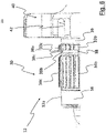
- reference numeral 10 wholly indicates a bicycle wheel hub assembly according to the present invention.
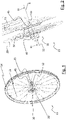
- Figures 1 and 2 illustrate a rear bicycle wheel 11.
- the hub assembly 10 comprises a hub 12 suitable for receiving a brake disc 20.
- the hub 12 is mounted on a frame of the bicycle between two opposite support arms of the rear wheel 11 at the respective free end portions of which housing seats of opposite free end portions of the hub 12 are provided.
- a caliper (not illustrated) of a disc brake is fixed onto the frame of the bicycle.
- the caliper is fixed in a conventional manner to one of the support arms of the wheel 11.
- the brake disc 20 rotates inside the space defined between the opposite brake pads.
- the brake pads are brought towards the brake disc 20, generating friction on the brake disc 20 and, consequently, braking the wheel 11.
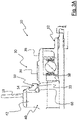
- the hub 12 extends along a longitudinal axis X that coincides with the rotation axis of the bicycle wheel and of the brake disc 20 ( figure 2 ).
- the hub 12 comprises a connection portion 30 to the brake disc 20, for receiving and locking in rotation the brake disc 20, and a pair of spoke-holding flanges 40 and 45, to which two respective pluralities of spokes 13 of the wheel 11 are fixed.
- the hub 12 comprises a connection portion 35 to a cassette (not illustrated).
- connection portion 30 to the brake disc 20 is arranged axially outer with respect to the spoke-holding flange 40, and the connection portion 35 to the cassette is arranged axially outer with respect to the spoke-holding flange 45.
- the connection portion 30 to the brake disc 20 is thus axially opposite the connection portion 35 to the cassette.
- the spokes 13 are placed under tension between the spoke-holding flanges 40 and 45 and the rim 14 of the wheel 11.
- the spokes 13 are preferably made of steel or aluminum alloy.
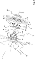
- the spoke-holding flange 40 comprises a plurality of appendages 42 extending radially each of which comprises a respective seat 42a configured to receive an end of a spoke 13.
- the appendages 42 are connected to a central crown 43 of the spoke-holding flange 40 which is connected to the hub 12.
- the central crown 43 is in one piece with the hub 12 and the appendages 42 are in one piece with the central crown 43.
- the seats 42a comprise an insertion opening 42b facing towards the connection portion 30, as better illustrated in figure 5 .
- Each spoke 13 is inserted, through the insertion opening 42b, in a respective seat 42a so that an end portion 13a of the spoke 13 ( figure 2 ) provided with a head (not illustrated) is radially held inside the seat 42a.
- the tensioning of the spoke 13 ensures that the spoke 13 cannot translate axially inside the seat 42a and come out from it.
- connection portion 30 of the hub 12 is formed on a hub body 12a that makes a radially outer surface of the hub 12.
- the hub body 12a is axially crossed, in radially inner position, by a hub pin 12b with respect to which the hub body 12a is rotatable about the rotation axis of the wheel 11.
- the hub pin 12b defines the rotation axis of the wheel 11.
- connection portion 30 comprises first rotational coupling members 32 to receive and rotationally hold the brake disc 20.
- the first rotational coupling members 32 are configured to be able to exchange pairs of forces between the brake disc 20 and the hub 12, so that the brake disc 12 can transfer the braking torque to the wheel 11.
- the first rotational coupling members 32 do not make any axial coupling between the hub 12 and the brake disc 20.
- the first rotational coupling members 32 comprise a first annular sector 33, axially external with respect to the spoke-holding flange 40, and a second annular sector 34, axially external with respect to the first annular sector 33.
- the first annular sector 33 is axially closer to the spoke-holding flange 40 with respect to the second annular sector 34.
- the first and second annular sector 33, 34 are shaped according to a shape coupling profile. With this term it is meant that the profile of the first and second annular sector 33, 34 have geometric features such as to allow the transmission of a torsion between the hub 12 and the brake disc 20.
- a shape coupling profile can for example be a polygonal profile, or a circular profile with an alteration (for example, levelled along a cord), and similar.
- first 33 and the second annular sector 34 comprise a fluted radially outer surface, in other words a radially outer surface that extends longitudinally and is provided with longitudinal flutes 33b, 34b defined between adjacent rectilinear radial projections 33c, 34c in the axial direction and projecting in the radial direction.
- All of the radial projections 33c, 34c of the first and second annular sector 33, 34 have equal extension in the radial direction.
- the radial projections 33c, 34c and the longitudinal flutes 33b, 34b of the first and second annular sector 33, 34 are axially aligned with each other.
- the radial projections 33c, 34c can have the same extension (like in the example illustrated in the attached figures) or at least one radial projection 33c, 34c can have a greater circumferential extension with respect to the other radial projections 33c, 34c to define a radial reference projection.
- the circumferential distance between the radial projections 33c, 34c (which defines the longitudinal flutes 33b, 34b) can be constant or, preferably, at least two radial projections 34c can be spaced by a greater circumferential distance with respect to the circumferential distance that separates the other radial projections, so as to define a longitudinal reference flute 33a, 34a (as illustrated in figure 5 ).
- the first and second annular sector 33, 34 are identical to one another except for the respective extension in the axial direction that is different.
- the extension in the axial direction of the second annular sector 34 is greater than the extension in the axial direction of the first annular sector 33.
- connection portion 30 further comprises a circumferential groove 38 that separates the first and second annular sector 33, 34 from one another.
- the circumferential groove 38 axially arranged between the first and the second annular sector 33, 34, has a greater radial depth than the radial depth of the flutes 33b, 34b of the first and second annular sector 33, 34.
- the groove 38 is defined between a first and a second annular shoulder 38a, 38b and a bottom wall 38c.
- the first annular shoulder 38a is adjacent to the first annular sector 33 and the second shoulder 38b is adjacent to the second annular shoulder 34.
- Each annular shoulder 38a, 38b extends radially outwards not beyond the flutes 33b, 34b of the first and second annular sector 33, 34.
- each annular shoulder 38a, 38b extends radially outwards until the outer surface of the hub body 12a is reached.
- Each annular shoulder 38a, 38b extends radially inwards until it joins with the bottom wall 38c.
- the bottom wall 38c is therefore arranged radially more internal than the flutes 33b, 34b of the first and second annular sector 33, 34.
- the circumferential groove 38 defines a recess that spaces the first 33 from the second annular sector 34.
- the extension in the axial direction of the groove 38 is preferably less than the extension in the radial direction of the first annular sector 33.
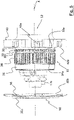
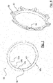
- the hub assembly 10 further comprises a spacer 50 configured to act as striking and reference element for the axial positioning of the brake disc 20 on the hub 12.
- the spacer 50 has a substantially annular shape and comprises a striking surface 50a for the brake disc 20 and an abutment surface 50b axially opposite the striking surface 50a.
- the spacer 50 further comprises a central opening 51 provided with second rotational coupling members 52 matching the first rotational coupling members 32.
- the second rotational coupling members 52 comprise a fluted radially inner surface 53 matching the fluted surface of the first rotational coupling members 32 of the first annular sector 33.
- the fluted radially inner surface 53 extends longitudinally and is provided with longitudinal flutes 53a defined between adjacent rectilinear radial projections 53b in the axial direction and projecting in the inner radial direction.
- the longitudinal flutes 53a match the radial projections 33c of the first annular sector 33 and the radial projections 53b match the longitudinal flutes 33b of the first annular sector 33.
- All of the radial projections 53b have equal extension in the radial direction.
- the circumferential distance between the radial projections 53b (which defines the longitudinal flutes 53a) can be constant (like in the example illustrated in the attached figures) or at least two radial projections 53b can be spaced by a greater circumferential distance with respect to the circumferential distance that separates the other radial projections 53b, so as to define a longitudinal reference flute.
- the radial projections 53b can have the same circumferential extension or, preferably, at least one radial projection 53b can have a greater circumferential extension with respect to the other radial projections 53b to define a radial reference projection 53c (as illustrated in figure 7 ).
- the radial reference projection 53c is configured to insert into the reference flute 33a of the first annular sector 33.
- the spacer 50 is fitted onto the connection portion 30 with the second rotational coupling members 52 engaged at the first rotational coupling members 32 of the coupling portion 30.
- the spacer 50 is fitted onto the first annular sector 33 and is rotatably constrained to it.
- the abutment surface 50b of the spacer 50 faces towards the spoke-holding flange 40, and is in contact and in abutment with the spoke-holding flange 40.
- the spacer 50 comprises a plurality of appendages 56 extending radially.
- the appendages 56 are in equal number to the appendages 42 of the spoke-holding flange 40 and have a shape such as to shield the insertion openings 42b of the seats 42a for holding spokes 13 in the axial direction.
- the appendages 56 of the spacer 50 rest substantially on the appendages 42 of the spoke-holding flange 40, at least partially axially covering the insertion openings 42b of the seats 42a for holding spokes 13.
- the appendages 56 of the spacer 50 make shoulders for the ends 13a of the spokes 13 inserted in the seats 42a of the spoke-holding flange 40, avoiding accidental axial withdrawals of the spokes 13 from the seats 42a.
- the longitudinal reference flute 33a of the first annular sector 33 in combination with the radial reference projection 53c of the spacer 50, orient the spacer 50 on the first annular sector 33 so that the appendages 56 of the spacer are positioned at the appendages 42 of the spoke-holding flange 40.
- Each appendage 56 of the spacer 50 comprises a small block 59 ( figure 8 ) that extends in the axial direction from the side facing towards the spoke-holding flange 40.
- the small blocks 59 are at least partially inserted in the insertion openings 42b of the seats 42a of the spoke-holding flange 40, so as to prevent dirt, mud and dust being able to slip into the seat 42a of the spoke 13.
- the spacer 50 can comprise a single annular appendage that extends in the radial direction until it shields the insertion openings 42b of the seats 42a for holding spokes 13.
- the appendages 56 of the spacer 50 can be made in one piece with the abutment surface 50a and the striking surface 50b (as illustrated in the example of figure 4 ), or they can be carried by an annular crown 57 distinct from the portion of spacer 50 having the abutment surface 50a and the striking surface 50b (as shown in the example of figures 7 and 8 ).
- the spacer comprises a substantially annular inner portion 58 carrying the abutment surface 50a and the striking surface 50b and the second rotational coupling members 52.
- the annular crown 57 is arranged radially external with respect to the inner portion 58 and can be coupled with it by mechanical interference.
- the annular crown 57 can for example be made of plastic or composite material.
- the striking surface 50a of the spacer 50 is axially arranged at the circumferential groove 38.
- the striking surface 50a is axially comprised between the first and the second shoulder 38a, 38b of the circumferential groove 38.
- the striking surface 50a is radially spaced from the bottom wall 38c of the circumferential groove 38 and can thus be machined, for example by chip removal, when the spacer 50 is already fitted on the first annular sector 33 of the hub 12.
- the striking surface 50a of the spacer 50 is made perfectly planar and perfectly perpendicular to the longitudinal axis X.
- the spacer 50 is made from any material that is not subject to oxidation even without surface coating layers.
- the spacer 50 is made of aluminum alloys of group 6000 or of stainless steel.
- the hub 12 can thus be made from a material that maximizes performance in terms of mechanical strength and lightness and can be coated with a layer that prevents the oxidation thereof.
- the hub 12 can be made of aluminum alloys having high mechanical performance, like for example Ergal (aluminum alloys of group 7000) or Avional (aluminum alloys of group 2000).
- the assembly 10 comprises an annular gasket 60, preferably toroidal, arranged between the hub 12 and the spacer 50 ( figure 3 ).
- a circumferential seat 39 for the annular gasket 60 is formed on the hub 12, axially inside the connection portion 30, between the first annular sector 33 and the spoke-holding flange 40 ( figure 5 ).
- the spacer 50 in axially inner position with respect to the second rotational coupling members 52, comprises a receiving seat 54 for the annular gasket 60.
- the annular gasket 60 creates mechanical interference between the spacer 50 and the hub 12, allowing the spacer 50 to remain in position during the assembly of the hub assembly 10.
- the brake disc 20 comprises a radially inner surface 22 matching the longitudinal flutes 34b and the radial projections 34c of the second annular sector 34.
- the brake disc 20 is fitted onto the connection portion 30 of the hub and in particular on the second annular sector 34 of the latter.
- the brake disc 20 is fitted onto the second annular sector 34 contacting the striking surface 50a of the spacer 50 that, acting as alignment surface, positions the brake disc 20 perfectly perpendicular to the longitudinal axis X.
- the assembly 10 comprises one or more thickening washers 70.
- the thickening washers 70 are axially arranged between the spacer 50 and the brake disc 20.
- the thickening washers 70 are arranged axially external with respect to the spacer 50, in contact with the striking surface 50a.
- all of the thickening washers 70 have the same thickness, in other words the same dimension in the axial direction.
- the thickening washers 70 have a thickness and a shape that are calibrated, so as to have perfectly flat and parallel opposite surfaces.
- the thickness of the thickening washers 70 is comprised between about 0.02 mm and about 0.2 mm, preferably it is 0.05 mm.
- a threaded portion 36 is provided, formed at a free end portion of the hub 12.
- the assembly 10 comprises a lock nut 80, able to be screwed onto the threaded portion 36 of the hub 12, which goes into abutment on an axially outer face 20a of the brake disc 20 and axially holds it on the connection portion 30.
- the lock nut 80 clamps the brake disc 20 to the hub 12, packing together the brake disc 20, the spacer 50 and, when present, one or more thickening washers 70.
- the mounting steps of the hub assembly 10 provide for mounting the spacer 50 with the relative annular gasket 60 on the connection portion 30 of the hub 12. During this operation, the spacer 50 is made to slide axially along the second annular sector 34 and reaches the first annular sector 33 on which it abuts, going into abutment against the spoke-holding flange 40.
- the striking surface 50a of the spacer 50 is arranged at the circumferential groove 38.
- the hub assembly 10 comprising the hub 12 and the spacer 50 is arranged on a machine tool and a levelling/grinding processing of the striking surface 50a of the spacer 50 mounted on the hub 12 is carried out.
- the assembly 10 thus worked is removed from the machine tool and then possible thickening washers 70 are mounted on the connection portion 30 of the hub 12.
- the thickening washers 70 are axially arranged in contact on the striking surface 50a of the spacer 50.
- the brake disc 20 is then mounted on the connection portion 30 of the hub 12, and in particular on the second annular sector 34 so that the brake disc 20 contacts the striking surface 50a of the spacer 50 or the thickening washers 70 (if present).
- lock nut 80 is mounted on the hub 12 so as to axially lock the components already mounted on the hub 12.
Landscapes
- Engineering & Computer Science (AREA)
- Mechanical Engineering (AREA)
- Braking Arrangements (AREA)
- General Engineering & Computer Science (AREA)
Claims (14)
- Nabe (12) eines Fahrradrades (11), umfassend einen Verbindungsabschnitt (30) zu einer Bremsscheibe (20) und wenigstens einen Speichenhalteflansch (40), der axial in Bezug auf den Verbindungsabschnitt (30) innen ist, wobei der Verbindungsabschnitt (30) erste Drehkopplungselemente (32) umfasst, wobei die ersten Drehkopplungselemente (32) einen ersten ringförmigen Sektor (33), der axial in Bezug auf den Speichenhalteflansch (40) außen ist, und einen zweiten ringförmigen Sektor (34), der axial in Bezug auf den ersten ringförmigen Sektor (33) außen ist, umfassen, wobei der Verbindungsabschnitt (30) des Weiteren eine umlaufende Nut (38) umfasst, die axial zwischen dem ersten und dem zweiten ringförmigen Sektor (33, 34) der ersten Drehkopplungselemente (32) angeordnet ist, dadurch gekennzeichnet, dass der erste und der zweite ringförmige Sektor (33, 34) jeweilige mehrere radiale Vorsprünge (33c, 34c) umfassen, die in Umfangsrichtung beabstandet sind und eine geradlinige Erstreckung in der axialen Richtung aufweisen.
- Nabe (12) nach Anspruch 1, wobei die radialen Vorsprünge (33c, 34c) des ersten und des zweiten ringförmigen Sektors (33, 34) axial miteinander ausgerichtet sind, wobei die in der radialen Richtung gegebene Erstreckung eines Vorsprungs (33c, 34c) gleich der in der radialen Richtung gegebenen Erstreckung eines beliebigen anderen radialen Vorsprungs (33c, 34c) des ersten und des zweiten ringförmigen Sektors (33, 34) ist.
- Nabe (12) nach Anspruch 2, wobei die radialen Vorsprünge (33c) des ersten ringförmigen Sektors (33) eine in der radialen und Umfangsrichtung gegebene Erstreckung aufweisen, die gleich derjenigen der entsprechenden Vorsprünge (34c) des zweiten ringförmigen Sektors (34) ist.
- Nabe (12) nach einem der vorhergehenden Ansprüche, wobei die in der axialen Richtung gegebene Erstreckung des zweiten ringförmigen Sektors (34) größer als die in der axialen Richtung gegebene Erstreckung des ersten ringförmigen Sektors (33) ist und wobei die in der axialen Richtung gegebene Erstreckung der umlaufenden Nut (38) kleiner als die axiale Erstreckung des ersten ringförmigen Sektors (33) ist.
- Nabe (12) nach einem der vorhergehenden Ansprüche, wobei der Speichenhalteflansch (40) mehrere sich radial erstreckende Fortsätze (42) umfasst, von denen jeder einen jeweiligen Sitz (42a) umfasst, der dafür ausgelegt ist, ein Ende (13a) einer Speiche (13) aufzunehmen, wobei die Sitze (42a) eine Einführöffnung (42b) umfassen, die hin zu dem ersten ringförmigen Sektor (33) der ersten Drehkopplungselemente (32) weist.
- Nabe (12) nach einem der vorhergehenden Ansprüche, wobei ein umlaufender Sitz (39) für eine ringförmige Dichtung (60) axial zwischen dem Speichenhalteflansch (40) und dem ersten ringförmigen Sektor (33) der ersten Drehkopplungselemente (32) angeordnet ist.
- Nabenbaugruppe (10) eines Fahrradrades (11), umfassend:eine Nabe (12) nach einem oder mehreren der Ansprüche 1 bis 6;einen Abstandshalter (50), der umfasst: eine Anschlagsoberfläche (50a) für die Bremsscheibe (20), eine Anlageoberfläche (50b), die axial zu der Anschlagsoberfläche (50a) entgegengesetzt ist, und eine zentrale Öffnung (51), die mit zweiten Drehkopplungselementen (52), die auf die ersten Drehkopplungselemente (32) abgestimmt sind, versehen ist;wobei der Abstandshalter (50) auf den Verbindungsabschnitt (30) aufgepasst ist und dabei die zweiten Drehkopplungselemente (52) an dem ersten ringförmigen Sektor (33) der ersten Drehkopplungselemente (32) in Eingriff sind, die Anlageoberfläche (50b) hin zu dem Speichenhalteflansch (40) weist und die Anschlagsoberfläche (50a) axial an der umlaufenden Nut (38) angeordnet ist.
- Nabenbaugruppe (10) nach Anspruch 7, wobei die Anschlagsoberfläche (50a) durch eine spanentfernende maschinelle Bearbeitung eben gemacht/geschliffen ist.
- Nabenbaugruppe (10) nach Anspruch 7 oder 8, wobei die Anlageoberfläche (50b) des Abstandshalters (50) mit dem Speichenhalteflansch (40) in Kontakt ist.
- Nabenbaugruppe (10) nach Anspruch 9 mit der Nabe (12) nach Anspruch 6, wobei der Abstandshalter (50) mehrere sich radiale erstreckende Fortsätze (56) umfasst, wobei jeder Fortsatz (56) des Abstandshalters (50) einen kleinen Block (59) umfasst, der wenigstens teilweise in eine jeweilige Einführöffnung (42b) der Sitze (42a) des Speichenhalteflansches (40) eingeführt ist.
- Nabenbaugruppe (10) nach einem der Ansprüche 7 bis 10, umfassend eine ringförmige Dichtung (60), die radial zwischen einer äußeren Oberfläche der Nabe (12) und einer inneren Oberfläche des Abstandshalters (50) angeordnet ist.
- Nabenbaugruppe (10) nach einem der Ansprüche 7 bis 11, umfassend wenigstens eine verdickende Unterlegscheibe (70), die axial in Bezug auf den Abstandshalter (50) außen an der Anschlagsoberfläche (50a) angeordnet ist.
- Nabenbaugruppe (10) nach einem der Ansprüche 7 bis 12, wobei der Abstandshalter (50) von einem radial inneren ringförmigen Abschnitt (58), der die Anschlagsoberfläche (50a) umfasst, und von einem radial äußeren ringförmigen Abschnitt (57), der dem radial inneren ringförmigen Abschnitt (58) zugeordnet ist, gebildet wird.
- Narbenbaugruppe (10) nach Ansprüchen 10 bis 13, wobei der radial äußere ringförmige Abschnitt (57) die mehreren sich radial erstreckenden Fortsätze (56) umfasst.
Applications Claiming Priority (1)
| Application Number | Priority Date | Filing Date | Title |
|---|---|---|---|
| IT102017000091932A IT201700091932A1 (it) | 2017-08-08 | 2017-08-08 | Mozzo di ruota per bicicletta e correlato assieme di mozzo |
Publications (2)
| Publication Number | Publication Date |
|---|---|
| EP3441235A1 EP3441235A1 (de) | 2019-02-13 |
| EP3441235B1 true EP3441235B1 (de) | 2022-06-15 |
Family
ID=60570159
Family Applications (1)
| Application Number | Title | Priority Date | Filing Date |
|---|---|---|---|
| EP18186717.7A Active EP3441235B1 (de) | 2017-08-08 | 2018-07-31 | Fahrradnabe und entsprechende nabenanordnung |
Country Status (6)
| Country | Link |
|---|---|
| US (1) | US10994572B2 (de) |
| EP (1) | EP3441235B1 (de) |
| JP (1) | JP2019043542A (de) |
| CN (1) | CN109383187A (de) |
| IT (1) | IT201700091932A1 (de) |
| TW (1) | TWI763897B (de) |
Citations (3)
| Publication number | Priority date | Publication date | Assignee | Title |
|---|---|---|---|---|
| EP1820666B1 (de) * | 2006-02-17 | 2008-12-31 | Shimano Inc. | Scheibenbremsennabe eines Fahrrads |
| EP1588932B1 (de) * | 2004-04-20 | 2009-07-08 | Shimano Inc. | Fahrradscheibenbremsrotorbaugruppe |
| EP1288117B2 (de) * | 2001-08-30 | 2013-06-19 | Shimano Inc. | Fahrradscheibenbremsnabe |
Family Cites Families (15)
| Publication number | Priority date | Publication date | Assignee | Title |
|---|---|---|---|---|
| US6540306B2 (en) * | 2001-06-29 | 2003-04-01 | Shimano Inc. | Bicycle disc brake hub |
| US7059686B2 (en) * | 2003-01-22 | 2006-06-13 | Shimano Inc. | Bicycle hub |
| JP2005188704A (ja) * | 2003-12-26 | 2005-07-14 | Shimano Inc | ディスクブレーキロータアセンブリ |
| TWM274312U (en) * | 2005-03-03 | 2005-09-01 | Joy Ind Co Ltd | Conversion device structure for disc brake hub |
| US7306292B2 (en) * | 2005-05-27 | 2007-12-11 | Shimano Inc. | Bicycle hub |
| US7331639B2 (en) * | 2005-11-04 | 2008-02-19 | Shimano Inc. | Bicycle rim |
| ITMI20062221A1 (it) | 2006-11-20 | 2008-05-21 | Campagnolo Srl | Mozzo per ruota di bicicletta e ruota di bicicletta comprendente tale mozzo |
| ITMI20062385A1 (it) * | 2006-12-13 | 2008-06-14 | Campagnolo Srl | Gruppo mozzo per ruota di bicicletta con freno a disco |
| TW201219239A (en) * | 2010-11-11 | 2012-05-16 | Shimano Kk | whose topics in that the manufacturing cost is not made to be increased and large diameter of the brake installation part can be inhibited in the wheel hub used in the bicycle capable of installing the brake apparatus |
| US9267560B2 (en) | 2013-07-31 | 2016-02-23 | Shimano Inc. | Bicycle disc brake rotor assembly and bicycle disc brake rotor |
| US9199509B2 (en) * | 2014-01-21 | 2015-12-01 | Shimano Inc. | Bicycle hub |
| CN103953670B (zh) * | 2014-05-04 | 2016-09-07 | 宏展五金塑胶制品(苏州)有限公司 | 自行车盘式制动器 |
| GB201414356D0 (en) * | 2014-08-13 | 2014-09-24 | Ison Disbribution Ltd | Rear wheel for bicycles and method of adapting a rear wheel |
| ITUB20156263A1 (it) * | 2015-12-03 | 2017-06-03 | Campagnolo Srl | Mozzo per una ruota di bicicletta |
| DE102016107752A1 (de) * | 2016-04-26 | 2017-10-26 | Dt Swiss Ag | Nabe und Laufrad |
-
2017
- 2017-08-08 IT IT102017000091932A patent/IT201700091932A1/it unknown
-
2018
- 2018-07-31 EP EP18186717.7A patent/EP3441235B1/de active Active
- 2018-08-07 TW TW107127395A patent/TWI763897B/zh active
- 2018-08-07 JP JP2018148080A patent/JP2019043542A/ja active Pending
- 2018-08-07 US US16/056,872 patent/US10994572B2/en active Active
- 2018-08-08 CN CN201810895420.9A patent/CN109383187A/zh active Pending
Patent Citations (3)
| Publication number | Priority date | Publication date | Assignee | Title |
|---|---|---|---|---|
| EP1288117B2 (de) * | 2001-08-30 | 2013-06-19 | Shimano Inc. | Fahrradscheibenbremsnabe |
| EP1588932B1 (de) * | 2004-04-20 | 2009-07-08 | Shimano Inc. | Fahrradscheibenbremsrotorbaugruppe |
| EP1820666B1 (de) * | 2006-02-17 | 2008-12-31 | Shimano Inc. | Scheibenbremsennabe eines Fahrrads |
Also Published As
| Publication number | Publication date |
|---|---|
| TW201919923A (zh) | 2019-06-01 |
| US20190047323A1 (en) | 2019-02-14 |
| CN109383187A (zh) | 2019-02-26 |
| JP2019043542A (ja) | 2019-03-22 |
| US10994572B2 (en) | 2021-05-04 |
| IT201700091932A1 (it) | 2019-02-08 |
| EP3441235A1 (de) | 2019-02-13 |
| TWI763897B (zh) | 2022-05-11 |
Similar Documents
| Publication | Publication Date | Title |
|---|---|---|
| US9180929B2 (en) | Sprocket assembly | |
| CN108700123B (zh) | 具有锁定连接的自行车飞轮 | |
| EP2025965B1 (de) | Bremsscheibenanordnung | |
| US10753412B2 (en) | Bicycle brake disc assembly | |
| JP2005308059A (ja) | 自転車用ディスクブレーキロータ組立体 | |
| GB2513441A (en) | Freewheel hub | |
| TWI748054B (zh) | 用於自行車的制動盤 | |
| CN104340317A (zh) | 自行车盘式制动器转子组件和自行车盘式制动器转子 | |
| US5494337A (en) | Bicycle wheel with a straight through spoke and hub combination | |
| TW202110702A (zh) | 鏈輪承載體以及用於自行車後輪的鏈輪承載體和變速盤的子群組件 | |
| CN113494552A (zh) | 刹车盘 | |
| AU2018328312B2 (en) | Disc brake rotor assembly | |
| JP2018028384A (ja) | 自転車用のブレーキディスク | |
| US20170284482A1 (en) | Cassette driver for a freewheel hub | |
| EP3441235B1 (de) | Fahrradnabe und entsprechende nabenanordnung | |
| JP7045810B2 (ja) | 自転車用のブレーキディスク | |
| JP4610532B2 (ja) | 自転車用ディスクブレーキハブ | |
| US10093129B2 (en) | Hub for a bicycle wheel | |
| US20170284481A1 (en) | Cassette driver for a freewheel hub | |
| GB2531408A (en) | Wheel for bicycles and method of adapting a bicycle wheel | |
| WO2003064882A1 (en) | Disk for a disk brake | |
| TW201544728A (zh) | 盤式制動器轉子,輪轂總成及制動器總成 | |
| GB2552596A (en) | Cassette driver for a freewheel hub |
Legal Events
| Date | Code | Title | Description |
|---|---|---|---|
| PUAI | Public reference made under article 153(3) epc to a published international application that has entered the european phase |
Free format text: ORIGINAL CODE: 0009012 |
|
| STAA | Information on the status of an ep patent application or granted ep patent |
Free format text: STATUS: THE APPLICATION HAS BEEN PUBLISHED |
|
| AK | Designated contracting states |
Kind code of ref document: A1 Designated state(s): AL AT BE BG CH CY CZ DE DK EE ES FI FR GB GR HR HU IE IS IT LI LT LU LV MC MK MT NL NO PL PT RO RS SE SI SK SM TR |
|
| AX | Request for extension of the european patent |
Extension state: BA ME |
|
| STAA | Information on the status of an ep patent application or granted ep patent |
Free format text: STATUS: REQUEST FOR EXAMINATION WAS MADE |
|
| 17P | Request for examination filed |
Effective date: 20190730 |
|
| RBV | Designated contracting states (corrected) |
Designated state(s): AL AT BE BG CH CY CZ DE DK EE ES FI FR GB GR HR HU IE IS IT LI LT LU LV MC MK MT NL NO PL PT RO RS SE SI SK SM TR |
|
| GRAP | Despatch of communication of intention to grant a patent |
Free format text: ORIGINAL CODE: EPIDOSNIGR1 |
|
| STAA | Information on the status of an ep patent application or granted ep patent |
Free format text: STATUS: GRANT OF PATENT IS INTENDED |
|
| RIC1 | Information provided on ipc code assigned before grant |
Ipc: B60B 1/00 20060101ALN20220210BHEP Ipc: B60B 27/02 20060101ALI20220210BHEP Ipc: B60B 27/00 20060101AFI20220210BHEP |
|
| INTG | Intention to grant announced |
Effective date: 20220315 |
|
| GRAS | Grant fee paid |
Free format text: ORIGINAL CODE: EPIDOSNIGR3 |
|
| GRAA | (expected) grant |
Free format text: ORIGINAL CODE: 0009210 |
|
| STAA | Information on the status of an ep patent application or granted ep patent |
Free format text: STATUS: THE PATENT HAS BEEN GRANTED |
|
| AK | Designated contracting states |
Kind code of ref document: B1 Designated state(s): AL AT BE BG CH CY CZ DE DK EE ES FI FR GB GR HR HU IE IS IT LI LT LU LV MC MK MT NL NO PL PT RO RS SE SI SK SM TR |
|
| REG | Reference to a national code |
Ref country code: CH Ref legal event code: EP Ref country code: GB Ref legal event code: FG4D |
|
| REG | Reference to a national code |
Ref country code: IE Ref legal event code: FG4D |
|
| REG | Reference to a national code |
Ref country code: DE Ref legal event code: R096 Ref document number: 602018036695 Country of ref document: DE |
|
| REG | Reference to a national code |
Ref country code: AT Ref legal event code: REF Ref document number: 1498141 Country of ref document: AT Kind code of ref document: T Effective date: 20220715 |
|
| REG | Reference to a national code |
Ref country code: LT Ref legal event code: MG9D |
|
| REG | Reference to a national code |
Ref country code: NL Ref legal event code: MP Effective date: 20220615 |
|
| PG25 | Lapsed in a contracting state [announced via postgrant information from national office to epo] |
Ref country code: SE Free format text: LAPSE BECAUSE OF FAILURE TO SUBMIT A TRANSLATION OF THE DESCRIPTION OR TO PAY THE FEE WITHIN THE PRESCRIBED TIME-LIMIT Effective date: 20220615 Ref country code: NO Free format text: LAPSE BECAUSE OF FAILURE TO SUBMIT A TRANSLATION OF THE DESCRIPTION OR TO PAY THE FEE WITHIN THE PRESCRIBED TIME-LIMIT Effective date: 20220915 Ref country code: LT Free format text: LAPSE BECAUSE OF FAILURE TO SUBMIT A TRANSLATION OF THE DESCRIPTION OR TO PAY THE FEE WITHIN THE PRESCRIBED TIME-LIMIT Effective date: 20220615 Ref country code: HR Free format text: LAPSE BECAUSE OF FAILURE TO SUBMIT A TRANSLATION OF THE DESCRIPTION OR TO PAY THE FEE WITHIN THE PRESCRIBED TIME-LIMIT Effective date: 20220615 Ref country code: GR Free format text: LAPSE BECAUSE OF FAILURE TO SUBMIT A TRANSLATION OF THE DESCRIPTION OR TO PAY THE FEE WITHIN THE PRESCRIBED TIME-LIMIT Effective date: 20220916 Ref country code: FI Free format text: LAPSE BECAUSE OF FAILURE TO SUBMIT A TRANSLATION OF THE DESCRIPTION OR TO PAY THE FEE WITHIN THE PRESCRIBED TIME-LIMIT Effective date: 20220615 Ref country code: BG Free format text: LAPSE BECAUSE OF FAILURE TO SUBMIT A TRANSLATION OF THE DESCRIPTION OR TO PAY THE FEE WITHIN THE PRESCRIBED TIME-LIMIT Effective date: 20220915 |
|
| REG | Reference to a national code |
Ref country code: AT Ref legal event code: MK05 Ref document number: 1498141 Country of ref document: AT Kind code of ref document: T Effective date: 20220615 |
|
| PG25 | Lapsed in a contracting state [announced via postgrant information from national office to epo] |
Ref country code: RS Free format text: LAPSE BECAUSE OF FAILURE TO SUBMIT A TRANSLATION OF THE DESCRIPTION OR TO PAY THE FEE WITHIN THE PRESCRIBED TIME-LIMIT Effective date: 20220615 Ref country code: LV Free format text: LAPSE BECAUSE OF FAILURE TO SUBMIT A TRANSLATION OF THE DESCRIPTION OR TO PAY THE FEE WITHIN THE PRESCRIBED TIME-LIMIT Effective date: 20220615 |
|
| PG25 | Lapsed in a contracting state [announced via postgrant information from national office to epo] |
Ref country code: NL Free format text: LAPSE BECAUSE OF FAILURE TO SUBMIT A TRANSLATION OF THE DESCRIPTION OR TO PAY THE FEE WITHIN THE PRESCRIBED TIME-LIMIT Effective date: 20220615 |
|
| PG25 | Lapsed in a contracting state [announced via postgrant information from national office to epo] |
Ref country code: SM Free format text: LAPSE BECAUSE OF FAILURE TO SUBMIT A TRANSLATION OF THE DESCRIPTION OR TO PAY THE FEE WITHIN THE PRESCRIBED TIME-LIMIT Effective date: 20220615 Ref country code: SK Free format text: LAPSE BECAUSE OF FAILURE TO SUBMIT A TRANSLATION OF THE DESCRIPTION OR TO PAY THE FEE WITHIN THE PRESCRIBED TIME-LIMIT Effective date: 20220615 Ref country code: RO Free format text: LAPSE BECAUSE OF FAILURE TO SUBMIT A TRANSLATION OF THE DESCRIPTION OR TO PAY THE FEE WITHIN THE PRESCRIBED TIME-LIMIT Effective date: 20220615 Ref country code: PT Free format text: LAPSE BECAUSE OF FAILURE TO SUBMIT A TRANSLATION OF THE DESCRIPTION OR TO PAY THE FEE WITHIN THE PRESCRIBED TIME-LIMIT Effective date: 20221017 Ref country code: ES Free format text: LAPSE BECAUSE OF FAILURE TO SUBMIT A TRANSLATION OF THE DESCRIPTION OR TO PAY THE FEE WITHIN THE PRESCRIBED TIME-LIMIT Effective date: 20220615 Ref country code: EE Free format text: LAPSE BECAUSE OF FAILURE TO SUBMIT A TRANSLATION OF THE DESCRIPTION OR TO PAY THE FEE WITHIN THE PRESCRIBED TIME-LIMIT Effective date: 20220615 Ref country code: CZ Free format text: LAPSE BECAUSE OF FAILURE TO SUBMIT A TRANSLATION OF THE DESCRIPTION OR TO PAY THE FEE WITHIN THE PRESCRIBED TIME-LIMIT Effective date: 20220615 Ref country code: AT Free format text: LAPSE BECAUSE OF FAILURE TO SUBMIT A TRANSLATION OF THE DESCRIPTION OR TO PAY THE FEE WITHIN THE PRESCRIBED TIME-LIMIT Effective date: 20220615 |
|
| PG25 | Lapsed in a contracting state [announced via postgrant information from national office to epo] |
Ref country code: PL Free format text: LAPSE BECAUSE OF FAILURE TO SUBMIT A TRANSLATION OF THE DESCRIPTION OR TO PAY THE FEE WITHIN THE PRESCRIBED TIME-LIMIT Effective date: 20220615 Ref country code: IS Free format text: LAPSE BECAUSE OF FAILURE TO SUBMIT A TRANSLATION OF THE DESCRIPTION OR TO PAY THE FEE WITHIN THE PRESCRIBED TIME-LIMIT Effective date: 20221015 |
|
| REG | Reference to a national code |
Ref country code: CH Ref legal event code: PL |
|
| REG | Reference to a national code |
Ref country code: DE Ref legal event code: R097 Ref document number: 602018036695 Country of ref document: DE |
|
| REG | Reference to a national code |
Ref country code: BE Ref legal event code: MM Effective date: 20220731 |
|
| PG25 | Lapsed in a contracting state [announced via postgrant information from national office to epo] |
Ref country code: MC Free format text: LAPSE BECAUSE OF FAILURE TO SUBMIT A TRANSLATION OF THE DESCRIPTION OR TO PAY THE FEE WITHIN THE PRESCRIBED TIME-LIMIT Effective date: 20220615 Ref country code: AL Free format text: LAPSE BECAUSE OF FAILURE TO SUBMIT A TRANSLATION OF THE DESCRIPTION OR TO PAY THE FEE WITHIN THE PRESCRIBED TIME-LIMIT Effective date: 20220615 |
|
| PLBE | No opposition filed within time limit |
Free format text: ORIGINAL CODE: 0009261 |
|
| STAA | Information on the status of an ep patent application or granted ep patent |
Free format text: STATUS: NO OPPOSITION FILED WITHIN TIME LIMIT |
|
| PG25 | Lapsed in a contracting state [announced via postgrant information from national office to epo] |
Ref country code: LU Free format text: LAPSE BECAUSE OF NON-PAYMENT OF DUE FEES Effective date: 20220731 Ref country code: LI Free format text: LAPSE BECAUSE OF NON-PAYMENT OF DUE FEES Effective date: 20220731 Ref country code: DK Free format text: LAPSE BECAUSE OF FAILURE TO SUBMIT A TRANSLATION OF THE DESCRIPTION OR TO PAY THE FEE WITHIN THE PRESCRIBED TIME-LIMIT Effective date: 20220615 Ref country code: CH Free format text: LAPSE BECAUSE OF NON-PAYMENT OF DUE FEES Effective date: 20220731 |
|
| 26N | No opposition filed |
Effective date: 20230316 |
|
| GBPC | Gb: european patent ceased through non-payment of renewal fee |
Effective date: 20220915 |
|
| PG25 | Lapsed in a contracting state [announced via postgrant information from national office to epo] |
Ref country code: SI Free format text: LAPSE BECAUSE OF FAILURE TO SUBMIT A TRANSLATION OF THE DESCRIPTION OR TO PAY THE FEE WITHIN THE PRESCRIBED TIME-LIMIT Effective date: 20220615 Ref country code: BE Free format text: LAPSE BECAUSE OF NON-PAYMENT OF DUE FEES Effective date: 20220731 |
|
| P01 | Opt-out of the competence of the unified patent court (upc) registered |
Effective date: 20230517 |
|
| PG25 | Lapsed in a contracting state [announced via postgrant information from national office to epo] |
Ref country code: IE Free format text: LAPSE BECAUSE OF NON-PAYMENT OF DUE FEES Effective date: 20220731 Ref country code: FR Free format text: LAPSE BECAUSE OF NON-PAYMENT OF DUE FEES Effective date: 20220815 |
|
| PG25 | Lapsed in a contracting state [announced via postgrant information from national office to epo] |
Ref country code: GB Free format text: LAPSE BECAUSE OF NON-PAYMENT OF DUE FEES Effective date: 20220915 |
|
| PG25 | Lapsed in a contracting state [announced via postgrant information from national office to epo] |
Ref country code: HU Free format text: LAPSE BECAUSE OF FAILURE TO SUBMIT A TRANSLATION OF THE DESCRIPTION OR TO PAY THE FEE WITHIN THE PRESCRIBED TIME-LIMIT; INVALID AB INITIO Effective date: 20180731 |
|
| PG25 | Lapsed in a contracting state [announced via postgrant information from national office to epo] |
Ref country code: MK Free format text: LAPSE BECAUSE OF FAILURE TO SUBMIT A TRANSLATION OF THE DESCRIPTION OR TO PAY THE FEE WITHIN THE PRESCRIBED TIME-LIMIT Effective date: 20220615 Ref country code: CY Free format text: LAPSE BECAUSE OF FAILURE TO SUBMIT A TRANSLATION OF THE DESCRIPTION OR TO PAY THE FEE WITHIN THE PRESCRIBED TIME-LIMIT Effective date: 20220615 |
|
| PG25 | Lapsed in a contracting state [announced via postgrant information from national office to epo] |
Ref country code: MT Free format text: LAPSE BECAUSE OF FAILURE TO SUBMIT A TRANSLATION OF THE DESCRIPTION OR TO PAY THE FEE WITHIN THE PRESCRIBED TIME-LIMIT Effective date: 20220615 |
|
| PG25 | Lapsed in a contracting state [announced via postgrant information from national office to epo] |
Ref country code: BG Free format text: LAPSE BECAUSE OF FAILURE TO SUBMIT A TRANSLATION OF THE DESCRIPTION OR TO PAY THE FEE WITHIN THE PRESCRIBED TIME-LIMIT Effective date: 20220615 |
|
| PG25 | Lapsed in a contracting state [announced via postgrant information from national office to epo] |
Ref country code: BG Free format text: LAPSE BECAUSE OF FAILURE TO SUBMIT A TRANSLATION OF THE DESCRIPTION OR TO PAY THE FEE WITHIN THE PRESCRIBED TIME-LIMIT Effective date: 20220615 |
|
| PGFP | Annual fee paid to national office [announced via postgrant information from national office to epo] |
Ref country code: DE Payment date: 20250729 Year of fee payment: 8 |
|
| PGFP | Annual fee paid to national office [announced via postgrant information from national office to epo] |
Ref country code: IT Payment date: 20250721 Year of fee payment: 8 |
|
| PG25 | Lapsed in a contracting state [announced via postgrant information from national office to epo] |
Ref country code: TR Free format text: LAPSE BECAUSE OF FAILURE TO SUBMIT A TRANSLATION OF THE DESCRIPTION OR TO PAY THE FEE WITHIN THE PRESCRIBED TIME-LIMIT Effective date: 20220615 |