EP3441234B1 - Procédé de transfert de films à froid - Google Patents
Procédé de transfert de films à froid Download PDFInfo
- Publication number
- EP3441234B1 EP3441234B1 EP18196930.4A EP18196930A EP3441234B1 EP 3441234 B1 EP3441234 B1 EP 3441234B1 EP 18196930 A EP18196930 A EP 18196930A EP 3441234 B1 EP3441234 B1 EP 3441234B1
- Authority
- EP
- European Patent Office
- Prior art keywords
- transfer
- layer
- film
- adhesive
- substrate
- Prior art date
- Legal status (The legal status is an assumption and is not a legal conclusion. Google has not performed a legal analysis and makes no representation as to the accuracy of the status listed.)
- Active
Links
Images

Classifications
-
- B—PERFORMING OPERATIONS; TRANSPORTING
- B44—DECORATIVE ARTS
- B44C—PRODUCING DECORATIVE EFFECTS; MOSAICS; TARSIA WORK; PAPERHANGING
- B44C1/00—Processes, not specifically provided for elsewhere, for producing decorative surface effects
- B44C1/16—Processes, not specifically provided for elsewhere, for producing decorative surface effects for applying transfer pictures or the like
- B44C1/165—Processes, not specifically provided for elsewhere, for producing decorative surface effects for applying transfer pictures or the like for decalcomanias; sheet material therefor
- B44C1/17—Dry transfer
- B44C1/1712—Decalcomanias applied under heat and pressure, e.g. provided with a heat activable adhesive
- B44C1/1716—Decalcomanias provided with a particular decorative layer, e.g. specially adapted to allow the formation of a metallic or dyestuff layer on a substrate unsuitable for direct deposition
-
- B—PERFORMING OPERATIONS; TRANSPORTING
- B44—DECORATIVE ARTS
- B44C—PRODUCING DECORATIVE EFFECTS; MOSAICS; TARSIA WORK; PAPERHANGING
- B44C1/00—Processes, not specifically provided for elsewhere, for producing decorative surface effects
- B44C1/16—Processes, not specifically provided for elsewhere, for producing decorative surface effects for applying transfer pictures or the like
- B44C1/165—Processes, not specifically provided for elsewhere, for producing decorative surface effects for applying transfer pictures or the like for decalcomanias; sheet material therefor
- B44C1/17—Dry transfer
- B44C1/1733—Decalcomanias applied under pressure only, e.g. provided with a pressure sensitive adhesive
- B44C1/1741—Decalcomanias provided with a layer being specially adapted to facilitate their release from a temporary carrier
Definitions
- the invention relates to a cold foil transfer process.
- a transfer foil consisting of a carrier foil, optionally a separating layer, and a transfer layer that can be detached from the carrier foil, is usually brought together in a printing unit with a substrate that has previously been applied in an adhesive applicator on its surface facing the transfer foil was provided with a full-area or pattern-shaped cold adhesive layer. In the areas of the substrate coated with the adhesive layer, the transfer layer of the transfer film is fixed to the substrate and detached from the carrier film.
- the used transfer film comprising the carrier film, the optional separating layer and any remnants of the transfer layer that have not been transferred to the substrate, is wound up while the substrate coated with the transfer layer is transported further in order to carry out further processing steps, coating or printing processes, turning over processes, punching or Perform cutting operations and the like.
- the printing unit for film application is usually formed from a smooth pressure roller and an equally smooth counter-pressure roller, which press the substrate and the transfer film against each other, the pressure roller coming into contact with the transfer film being covered in particular with a compressible rubber blanket or printing blanket.
- the EP 0 578 706 A describes a foil printing process and a foil transfer machine which are used for cold foil coating of surfaces of substrates by means of transfer foils.
- the EP 1 880 848 A2 discloses a device and a method for transferring layers of a transfer film onto a printing material or a substrate by means of a cold stamping device, a film application module being used in a sheet-fed rotary printing machine.
- a turning device enables the printing material to be turned over and printing and / or embossing of the printing material on both sides.
- further coating or printing units are connected upstream and / or downstream of the film application module.
- the WO 03/020519 A1 discloses a method of applying a transferable layer from a film to a substrate, wherein an adhesive is first applied in a pattern to the substrate and the film using a droplet separator head. The adhesive is then cured and the transferable layer is transferred from the film to the substrate according to the pattern.
- the DE 40 21 908 A1 relates to a multilayer optically variable element with an adhesive layer, a layer exhibiting an optically variable effect, a protective layer and a removable carrier layer, the protective layer being designed as a self-supporting and dimensionally stable layer with a thickness of a few micrometers.
- U.S. 3,726,710 discloses curable silicone release compositions containing a crosslinkable olefinic organopolysiloxane compound and a photosensitizer and a paper substrate coated therewith.
- the U.S. 4,536,434 relates to a release agent formulation for use in a heat transferable laminate, wherein an image is transferred from a carrier layer to an object by applying heat to the carrier layer.
- U.S. 6,613,412 discloses a support for decorative graphics and lettering applied to a substrate.
- the UV exposure of the adhesive takes place after the transfer film and substrate or transfer layer and substrate have been brought together. It is necessary here that either the transfer film, the transfer layer or the substrate to be coated is at least partially permeable to the UV radiation used to crosslink the adhesive.
- the transfer film as a whole or only the transfer layer is provided with a permeability for UV radiation, with currently transfer films or transfer layers with a permeability of ⁇ 10% for UV radiation in the range from 250 nm to 400 nm can be used.
- a first transfer film for use in a cold foil transfer process comprising a carrier film and a transfer layer that can be removed from the carrier film, the transfer layer comprising, starting from the carrier film, a transparent release layer, an optional transparent protective lacquer layer, at least one decorative layer and at least one primer layer made from a thermoplastic adhesive which can be activated in a temperature range of> 90 ° C.
- the first transfer film has, in particular, on its side facing away from the carrier film, a primer layer made of a thermoplastic adhesive which, during cold foil transfer, acts as an adhesion promoter layer for a cold adhesive, in particular an adhesive that cross-links under UV radiation, on a substrate. It has been shown, surprisingly, that a particularly strong connection between the transfer layer and the substrate and a particularly strong connection between the transfer layer and the substrate and / or the primer layer can be formed. This is astonishing because thermoplastic adhesives, also known as hot adhesives, and cold adhesives, especially adhesives that crosslink under UV radiation, are substances whose adhesive effects are based on completely different chemical-physical principles.
- the structure of the first transfer foil for use in a cold foil transfer process thus resembles a hot stamping foil.
- a transfer film in the form of a hot stamping film which has a carrier film and a transfer layer that can be detached from the carrier film, in a cold foil transfer process in which the transfer layer is placed on a substrate by means of a cold adhesive, in particular an adhesive that cross-links under UV radiation being fixed is ideal.
- hot stamping foils have a hot-melt adhesive layer which is heated during the hot stamping process and - usually with additional application of pressure - forms an adhesive bond with the substrate to be stamped. After cooling, the transfer layer is fixed to the substrate by means of the hot-melt adhesive layer, so that the carrier film can be peeled off.
- a second transfer film for use in a cold foil transfer process comprising a carrier film and a transfer layer that can be removed from the carrier film, the transfer layer comprising, starting from the carrier film, a transparent polymeric release layer, an optional transparent protective lacquer layer, at least one decorative layer and at least one primer layer and that in a temperature range from 15 to 35 ° C.
- the detachment force of the transfer layer from the carrier film is in the range from 15 to 35 cN / cm, in particular in the range from 20 to 30 cN / cm.
- the detachment force of the release layer from the carrier foil and the force for detaching areas from the transfer layer under transfer conditions must generally be less than the adhesive force between substrate and transfer layer, which is due to the type of cold adhesive used and its bond with the substrate on the one hand and the primer layer on the other. Only then can the transfer layer or areas of the transfer layer become detached from the carrier film during the transfer and remain attached to the substrate.
- the release force of the release layer from the carrier film must be so high that safe handling of the transfer film is ensured without the transfer sheet becoming detached from the carrier film, for example when the transfer film is unwound from a supply roll and / or when the transfer film is being transported , possibly via deflection devices, into a cold foil transfer unit.
- the transfer layer is transferred to the substrate in a temperature range from 10 to 40.degree. C., preferably from 15 to 35.degree.
- the peeling force of the transfer layer from the carrier film in the range from 15 to 35 cN / cm, in particular in the range from 20 to 30 cN / cm, is low in the temperature range from 15 to 35 ° C compared to a conventional hot stamping film.
- the detachment force of the transfer layer from the carrier foil is set so that it is significantly higher, at least by a factor of 2-3, than with the transfer foil in the temperature range from 10 to 40 ° C, since otherwise the transfer layer of the hot stamping foil is could detach in an undesirable manner even before the hot stamping step, for example during storage or transport.
- a peeling force of the transfer layer from the carrier foil in the range of 15 to 35 cN / cm is only achieved in the working temperature range, i.e. at around 120 to 180 ° C.
- the detachment force indicates the force (usually in units of force / length) that has to be applied to detach two layers from one another; there is a positive correlation between the peel force of a first layer from a second layer and the adhesion between the first and second layers.
- the determination of the required release force between the carrier film and the transfer layer of the second transfer film was determined according to FINAT test method No. 3 (FTM3, low speed release force).
- the second transfer film measured release forces from the carrier film that were up to 250%, especially up to 150% higher.
- the transfer layer was still sufficiently removable and, in contrast to transfer layers of transfer films which have wax-based or silicone-based release layers, could be overprinted very well, with very good adhesion of the dried or cured printing ink on the transfer layer.
- the at least one primer layer is formed from a thermoplastic adhesive that is in one Temperature range of> 90 ° C can be activated, as was also defined for the first transfer film.
- the release layer is a polymeric release layer and, in a temperature range from 15 to 35 ° C, the release force of the transfer layer from the carrier film is in the range from 15 to 35 cN / cm, in particular in the range from 20 to 30 cN / cm, as was also defined for the second transfer film.
- each transfer film if the release layer is free from wax and / or free from silicone.
- a transfer film does not have a conventional wax or silicone-based release layer, which hitherto had the effect that transfer layers of transfer films that were equipped with it were only partially or not at all with conventional printing inks, in particular UV-curing printing inks, UV-curing varnishes, hybrid inks or -varnish, were printable.
- the use of a release layer based on an acrylate copolymer is particularly preferred for the transfer films.
- the release layer of a transfer film is preferably designed in such a way that it is released from the carrier film and remains completely on the transfer sheet.
- the adhesion of the release layer to the carrier film in the temperature range from 15 to 35 ° C. is lower than the adhesion of the release layer to the other layers of the transfer layer adjoining it; this means that the detachment force of the detachment layer from the optional protective lacquer layer or the decorative layer is greater than the detachment force of the detachment layer from the carrier film.
- the detachment force of the detachment layer from the optional protective lacquer layer or the decorative layer in the temperature range from 15 to 35 ° C. is at least 1.5 times greater than the detachment force of the detachment layer from the carrier film.
- the release layer can also be designed in such a way that the release force of the release layer from the carrier film in a temperature range of 15 to 35 ° C is greater, in particular at least 1.5 times greater, than the release force of the release layer from an adjacent layer of the transfer layer, in particular the optional protective lacquer layer or the decorative layer.
- the release layer remains completely or partially on the carrier film when the carrier film is peeled off from the transfer layer.
- the transfer film has a protective lacquer layer between the release layer and the at least one decorative layer that is easy to print on. After the carrier film and the at least partially adhering release layer have been peeled off from the transfer film, the protective lacquer layer forms the topmost, outer layer of the transfer layer and can be printed with conventional printing inks.
- the release layer of a cold-transferred transfer layer of a transfer film is preferably formed with a surface tension in the range from 45 to 60 mN / m, in particular in the range from 50 to 55 mN / m, the surface tension being determined by means of a contact angle measurement at around 20 ° C.
- surface tensions in the range of 30 to 45 mN / m, in particular in the range of 35 to 40 mN / m were determined for conventional wax-based release layers, the surface tension also being determined by means of a contact angle measurement at around 20 ° C.
- the release layer preferably has a thickness in the range from 0.01 to 0.5 ⁇ m, preferably in the range from 0.01 to 0.3 ⁇ m, more preferably from 0.1 to 0.2 ⁇ m.
- This comparatively small thickness of the release layer allows the transfer layer to be detached from the transfer film with a sharp edge and cleanly.
- the achievable accuracy and the achievable resolution can correspond comparatively exactly to the layout of the cold adhesive layer applied partially, preferably on the substrate, without deviating significantly from it, whereby a high register accuracy of the cold foil layout can be achieved with a possibly existing print layout made of conventional printing inks. With this sharp-edged partial detachment, the small thickness of the detachment layer results in only very small and very few so-called flakes, i.e.
- the at least one primer layer has a thickness in the range from 1 ⁇ m to 5 ⁇ m, in particular in the range from 1.5 ⁇ m to 3 ⁇ m.
- the at least one primer layer can be colored, for example to enhance a contrast to the substrate, etc.
- the at least one primer layer which is intended to adjoin the cold adhesive, has a surface roughness in the range from 100 to 180 nm, in particular in the range from 120 to 160 nm.
- the surface roughness is determined, among other things, by the application method and the formulation of the primer layer. It was found that a lower surface roughness, but surprisingly also a higher surface roughness of the primer layer, leads to a reduction in the achievable adhesion between a cold adhesive and the transfer layer.
- the surface roughness of the primer layer was determined by means of an interference microscope.
- primer layers which differ in their chemical and / or physical properties, in order to achieve optimal adhesion on the one hand in the direction of the adjoining decorative layer (s) and on the other to achieve optimal adhesion in the direction of the cold adhesive, in particular UV adhesive, which comes into contact with the transfer layer.
- Tesatest a Tesa-proof adhesion
- the transfer layer is achieved between the transfer layer and the substrate, with the Tesatest already after a few minutes when using a conventionally drying cold adhesive and the Tesatest immediately after exposure to UV light when using a UV adhesive could be rated as passed. Over 90% of the transfer layer remained on the substrate.
- each transfer film possibly also just its transfer layer, has a permeability in the range from 5 to 70%, in particular in the range from 20 to 40%, for UV radiation in the wavelength range from 250 nm to 400 nm.
- This enables particularly rapid and, in particular, complete curing of a cold adhesive based on an adhesive that cross-links under UV radiation on the substrate, which further improves the adhesion of the transfer layer to the substrate. Only when the amount of irradiation is sufficiently high is the adhesive crosslinking under UV irradiation fully crosslinked and cured and achieves a high bond strength, so that the transfer layer areas transferred to the substrate are reliably prevented from becoming detached from the substrate.
- the decisive factor for the UV permeability of a transfer film is the layer of a transfer film which has the lowest UV permeability of all the layers present.
- the carrier film preferably has a thickness in the range from 7 to 23 ⁇ m.
- the carrier film is preferably formed from polyester, polyolefin, polyvinyl, polyimide or ABS.
- the use of carrier films made of PET, PC, PP, PE, PVC or PS is particularly preferred.
- a carrier film made of PET has proven itself.
- the overall thickness of the transfer film is in particular in the range from 9 to 25 ⁇ m, in particular in the range from 13 to 16 ⁇ m.
- the transfer layer has a protective lacquer layer.
- the protective lacquer layer provides protection against mechanical and / or chemical stress on the transfer layer on a substrate.
- the protective lacquer layer preferably has a thickness in the range from 0.8 to 3 ⁇ m, in particular from 0.9 to 1.3 ⁇ m, and can furthermore be crystal clear, colorless or colored or at least partially colored.
- the at least one decorative layer of the transfer layer is preferably formed by a metallic layer or a dielectric layer. It has proven useful if the at least one decorative layer has a thickness in the range from 8 to 500 nm.
- the metallic layer only has a layer thickness in the range from 8 nm to 15 nm, preferably in the range from 10 nm to 12 nm. It is also possible for the metallic layer to have a layer thickness in the range from 12 nm to 15 nm. This results in good visibility and a decorative effect of the metallic layer in combination with high permeability for UV radiation (optical thickness (OD) approx. 1.2).
- OD optical thickness
- metal layers with a thickness in the range of more than 15 nm are usually used in order to achieve optimum brilliance. Due to the resulting large optical thickness of about 2, however, such conventional metal layers are not sufficiently UV-permeable for the use of a UV adhesive as a cold adhesive.
- the metallic layer is formed from aluminum, silver, gold, copper, nickel, chromium or an alloy comprising at least two of these metals.
- the dielectric layer is in particular formed from at least one material from the group comprising metal oxide, polymer or lacquer.
- the variable x is preferably in the range from 0 to 3.
- the decorative layer can in particular also be formed from an HRI material that is permeable in the UV range, such as CdSe, CeTe, Ge, HfO 2 , PbTe, Si, Te, TiCl or ZnTe.
- an HRI material that is permeable in the UV range, such as CdSe, CeTe, Ge, HfO 2 , PbTe, Si, Te, TiCl or ZnTe.
- a decorative layer has a diffractive relief structure for generating optically variable effects and / or a macrostructure for generating three-dimensional effects or depth effects.
- diffractive relief structures which are formed in particular in a transparent lacquer layer, different optical effects, so-called optically variable effects, can be achieved depending on the viewing angle, such as holograms, three-dimensional representations with viewing angle dependent, kinematic effect, etc.
- HRI High Refractive Index
- a highly reflective metallic layer or dielectric HRI layer with a comparatively high to very high refractive index, in particular made of a metal oxide.
- HRI High Refractive Index
- Such a highly reflective layer can be formed over the entire surface or in the form of a pattern.
- Decorative layer a layer with optically variable pigments, luminescent substances, magnetic or electrically conductive substances, a colored lacquer layer, a thin film stack with viewing angle dependent interference color effect, a liquid crystal layer, or a combination of the above-mentioned layers comprising metallic layers, dielectric layers, etc., can be used as Decorative layer (s) serve.
- the object is achieved by a cold foil transfer process in which a cold adhesive, in particular an adhesive that cross-links under UV radiation, is applied to a substrate and connected to a transfer layer of a transfer foil, in that a transfer foil is brought together with the substrate, which is a carrier foil and a comprises transfer layer removable from the carrier film, the transfer layer starting from the carrier film comprising a transparent release layer, an optional transparent protective lacquer layer, at least one decorative layer and at least one primer layer made of a thermoplastic adhesive that can be activated in a temperature range of> 90 ° C, with Merging the transfer film with the substrate which shows at least one primer layer of the transfer film to form the cold adhesive, and furthermore the cold adhesive is cured, in particular the adhesive that cross-links under UV radiation is irradiated and cross-linked, with an adhesive bond ung is formed with the transfer layer of the transfer film.
- a cold adhesive in particular an adhesive that cross-links under UV radiation
- cold foil transfer units or cold foil transfer assemblies can be integrated or mounted comparatively easily in or on common multicolor printing machines.
- the cold foil transfer process results in a substrate that is fully or only partially coated with a transfer layer, which has a high abrasion and scratch resistance with regard to the first transfer foil, in particular due to the special type of bonding between the transfer layer and the substrate described in detail above, and with regard to the second transfer foil in particular due to the Above described in detail, the special design of the release layer is particularly easy to print.
- UV radiation it is particularly preferred to apply the UV radiation to a cold adhesive in the form of an adhesive that cross-links under UV radiation from the transfer film or transfer layer, since a wide variety of substrates, which can be transparent or impermeable to UV radiation, are processed and with the same Transfer film can be coated. However, it is just as possible to emit the UV radiation only or additionally from the substrate, provided that the substrate is transparent to the radiation used.
- the duration of irradiation of the UV adhesive with UV radiation is preferably in the range of less than one second, with high pressure mercury lamps, doped high pressure mercury lamps, carbon arc lamps, xenon arc lamps, metal halogen lamps, UV LEDs or suitable UV lasers being used, for example .
- electron beam hardening can also be carried out.
- sheet-fed printing machines which process sheets of 75 cm length, for example, and where a range of approx. 8 to 10 cm of the sheet length is irradiated with a UV lamp with an output in the range of 160 to 200 W / cm, approx 10000 sheets per hour can be processed.
- cold adhesive in particular the adhesive which cross-links under UV radiation, to the substrate
- cold adhesive can be used can of course also or additionally be applied to the at least one primer layer of the transfer film.
- the cold adhesive can be applied over the entire surface or only partially to the substrate and / or the primer layer of the transfer film.
- a pattern-like formation of the transfer layer on the substrate is possible in both cases, since only partial activation of the cold adhesive can take place when cold adhesive is applied over the entire surface.
- a UV adhesive is used as the cold adhesive, which is applied over the entire surface, for example to the substrate, then this can be partially exposed after the substrate and transfer film have been brought together, for example via a shadow mask.
- the UV adhesive is only cured in the exposed areas and only fixes the transfer layer to the substrate there, while in unexposed areas the transfer layer remains on the carrier film and can be removed from the substrate again with this.
- the cold adhesive applied over the entire surface to the substrate can also be exposed in pattern form a first time before it is brought together with the transfer film, so that it is already cured in certain areas and can no longer develop adhesive force if it is exposed over the entire surface a second time after it has been brought together with the transfer film and the previously not cured adhesive areas are cured and connected to the transfer layer.
- the carrier film has been peeled off the substrate, the areas that were exposed in pattern form the first time now remain without a transfer layer.
- the carrier film When cold adhesive is applied in a pattern to the substrate and / or the primer layer of the transfer film, after the substrate and transfer film have been brought together, the carrier film can be peeled off from the transfer layer at different times. In this way, the carrier film can be peeled off immediately after the substrate and transfer film have been brought together and before the cold adhesive has hardened. For this it is necessary that the adhesion of the transfer layer to the cold adhesive that has not yet or not yet fully cured is higher than the force required to detach a transfer layer area from the transfer layer and to overcome the adhesion to the carrier film. If an adhesive that cross-links under UV irradiation is used, then UV permeability of the transfer layer is sufficient.
- This method is often used in sheet-fed offset printing machines.
- the carrier film can be peeled off after the substrate and transfer film have been brought together and only after the cold adhesive has cured. It is not necessary here for the adhesion of the transfer layer to the cold adhesive that has not yet or not yet fully cured to be higher than the force required to detach a transfer layer area from the transfer layer and to overcome the adhesion to the carrier film. Only the adhesion of the transfer layer to the fully cured cold adhesive and also to the substrate must be higher than the force required to detach a transfer layer area from the transfer layer and to overcome the adhesion to the carrier film when the carrier film is peeled off.
- a single composition can be used for the cold adhesive or several different cold adhesives, which differ in terms of their chemical and / or physical properties, can be used next to one another on the substrate. It is often necessary to use a separate printing unit for each cold adhesive. A locally different adhesion of the transfer layer to the substrate can be achieved, so that any manipulative attempts to detach it to change or replace the substrate are made more difficult and the security against forgery is increased.
- the cold adhesive in particular the adhesive or UV adhesive which cross-links under UV radiation
- the cold adhesive is applied to the substrate in an application amount in the range from 1 to 3 g / m 2.
- the amount of cold adhesive must be varied depending on the absorbency of the substrate used, with low-absorbent and / or open-pore-free substrates in particular with cold adhesive amounts in the range of 1 to 2 g / m 2 and more absorbent and / or open-pored substrates, in particular with cold adhesive amounts can be applied in the range of 2 to 3 g / m 2 .
- UV adhesives in principle, all commercially available cold adhesives, in particular adhesives that crosslink under UV radiation, so-called UV adhesives, are suitable for use in the process.
- UV adhesives are used in particular in combination with a substrate made of paper or film.
- the UV radiation used for irradiating the adhesive crosslinking under UV irradiation is radiation with a wavelength in the range from 250 to 400 nm or the radiation used has a maximum in this wavelength range.
- paper, cardboard, plastic film, metal foil or a laminate comprising at least two of these materials is used as the substrate.
- the fully coated and optionally further processed and / or printed substrates are preferably used as wet labels, inmold labels, magazines, packaging material, such as, for example, folding boxes, and the like.
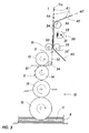
- Figure 1 shows a cross section through a transfer film 40, which has a carrier film 42 and a transfer layer 41 that can be detached from the carrier film 42.
- the transfer layer 41 comprises, in this order, a transparent release layer 43, a transparent protective lacquer layer 44, a decorative layer 45 and a primer layer 46.
- the carrier film 42 is a PET film with a thickness in the range from 7 to 23 ⁇ m.
- the thickness of the carrier film 42 is in particular 12 ⁇ m here.
- the transparent release layer 43 is a wax and silicone-free layer.
- the disperse part is 43.6 mN / m, the polar part 9.1 mN / m.
- the transparent protective lacquer layer 44 is an optional layer which is used in particular to protect the decorative layer 45 from mechanical and / or chemical stress.
- the protective lacquer layer 44 is in particular a lacquer layer based on nitrocellulose and acrylate polymers.
- the decorative layer 45 here is a metallic layer made of aluminum with a layer thickness in the range from 12 to 15 nm. Sputtering or vapor deposition are particularly suitable as coating methods for applying such metallic layers. Alternatively or in combination, colored lacquer layers, luminescent layers, magnetic layers, thin film stacks with viewing angle dependent interference color effect, liquid crystal layers, or a combination of the aforementioned layers comprising the metallic layers, etc. can serve as decorative layer (s).
- the primer layer 46 is formed from a thermoplastic adhesive and has a thickness in the range from 1 to 5 ⁇ m, in particular in the range from 1.5 to 3 ⁇ m.
- the primer layer 46 is just a single layer here. But there can also be two or more coats of primer to get on to achieve optimal adhesion in the direction of the adjoining decorative layer (s) on the one hand and optimal adhesion in the direction of the cold adhesive coming into contact with the transfer layer on the other.
- the primer layer 46 has a surface roughness of 137 ⁇ m (mean value) on its side facing away from the carrier film.
- Figure 2 shows a cross section through a flexible substrate 51, to which a cold adhesive 11 is applied in a pattern in the form of an adhesive which cross-links under UV radiation.
- the flexible substrate 51 can be a paper web, a plastic film or a printed sheet.
- a plastic film is preferably made of polyester, polypropylene, polyethylene, polycarbonate, polystyrene, PVC or ABS with a film thickness in the range from 6 to 200 ⁇ m, in particular from 19 to 38 ⁇ m.
- a picture printing material or Chromolux for paper sheets or webs, it has proven useful if these are coated, for example with a picture printing material or Chromolux.
- the substrate 51 will also have further layers or film areas applied in previous method processes.
- additional layers are, for example, printing ink layers, lacquer layers and / or metal layers, etc.
- applied film areas can be formed by transfer layer areas of transfer films, labels, etc. It is also possible here for these further layers or applied film areas to be present only partially on the substrate 51 or to cover the surface of the substrate 51 as a whole.
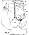
- Figure 3 shows a cold foil transfer unit comprising a printing station 10, an exposure station 20, three rollers 31, 32 and 33 and a deflection roller 34.
- the printing station 10 is preferably an offset or flexographic printing station. However, it is also possible that the printing station 10 is a gravure printing station.
- the substrate 51 is continuously fed to the printing station 10 and partially printed with the cold adhesive 11 in the form of the adhesive which cross-links under UV radiation.
- the transfer layer 41 of the Transfer film 40 take place with the UV-crosslinking adhesive.
- the printing station 10 has a tub 9 in which the UV-crosslinking adhesive is provided.
- the UV-crosslinking adhesive is applied to a printing cylinder 14 by means of several transfer rollers 12, 13.
- the printing cylinder 14 then prints the flexible substrate 51 running through between the printing cylinder 14 and an impression cylinder 15 in the form of a pattern with the cold adhesive 11, preferably in a thickness in the range from 0.5 to 10 ⁇ m.
- the amount of cold adhesive 11 applied to the substrate 51 is in particular in the range from 1 to 3 g / m 2 .
- the substrate 51 is here in particular transported from roller blind to roller.
- the substrate 51 processed in this way by the printing station 10 is fed as a substrate 52 partially printed with the UV-crosslinking adhesive via the deflection roller 34 to the pair of rollers 31, 32, which continuously applies the transfer film 40 to the substrate 52 printed with UV adhesive.
- the roller 32 and the counter-pressure roller 31 form a transfer nip in which, on the one hand, the UV-crosslinking adhesive coated substrate 52 and on the other hand the transfer film 40 are drawn in.
- the substrate 52 coated therewith passes through a drying channel in which the cold adhesive 11 is dried and / or pre-cured, for example at a temperature of 100 to 120 ° C., before it is drawn into the transfer gap.
- the roller 32 of the roller pair 31, 32 is preferably covered on its periphery with a printing blanket or rubber blanket 32 '.
- the rubber blanket 32 ' is usually composed of several layers which have different compressibility and elasticity. The individual layers are glued to one another over their entire surface or mechanically coupled to one another, in particular by means of a rail.
- the rubber blanket 32 ' comprises, in particular, a carrier layer made of a textile fabric to which the other layers that are present are connected.
- the upper layer or cover layer of the rubber blanket 32 ' which comes into contact with the transfer foil in the cold foil transfer unit, is preferably designed to be antistatic and detergent-resistant.
- the rubber blanket 32 ' is attached to the roller 32, whereby layers of paper can be inserted between the roller 32 and the rubber blanket 32' to set an optimal contact pressure of the roller 32, and bearer rings (not shown here) are arranged on both sides of the roller 32.
- a bearer ring is part of the printing unit construction of modern printing machines. Bearer rings on printing machines are arranged on the sides of the printing cylinders or rollers. The bearer rings are made of hardened steel with high rolling resistance and roll off one another with high preload. The main task of bearer rings is to prevent the torsional vibrations in the oscillatory, mechanically tensioned system of cylinders and gears. Furthermore, the bearer rings increase the flexural strength of the cylinder pairing. This shifts the resonance frequency into uncritical ranges and reduces bending vibrations that the impact excites when rolling over channels in the rollers or cylinders.
- the gradation of the bearer ring diameter - slightly smaller on the plate cylinder than on the blanket cylinder - enables mechanical tension to be introduced in the running direction between the bearer rings and the gears. In this way, a clear flank position of the gears can be ensured even with strong momentary impulses when the canal is rolled over.
- the plates and blanket cylinders are supported on one another via the bearer rings at both ends of the cylinder.
- the bearer ring has the same diameter as the pitch circle of the driving gear.
- the rubber blanket is usually underlaid in such a way that it is compressed by 1/10 mm by the pressure plate in order to compensate for certain surface unevenness and to build up the required surface pressure. It has proven to be beneficial to open printing plates 1/10 mm above bearer ring and to place rubber blankets at bearer ring height.
- the bearer rings also serve as a reference height in order to be able to measure the lift heights on the cylinders.
- the bearer rings primarily ensure that the cylinder runs smoothly thanks to the preload applied during assembly and the avoidance of quality-reducing and noise-producing effects of load fluctuations as a result of channel overrolling. Bearing force fluctuations can produce quality-reducing stripes in homogeneous, larger screen areas due to minimally different tone value increases.
- Cold foil transfer usually works "over Schmitz” in order to be able to apply sufficient pressure, although it is also possible to work a few hundredths of a millimeter “under Schmitz”.
- the speed of the transfer film and the transfer film tension can be influenced to a small extent via the selected circumference of the rubber blanket 32 '.
- the transfer film 40 shown is pulled off a supply roll (not shown separately) and placed on the side of the transfer layer 41 (see FIG Fig. 1 ) brought into contact with the substrate 52 printed with UV-crosslinking adhesive. This results in a composite 53 composed of the substrate 52 printed with UV-crosslinking adhesive and the transfer film 40.
- the carrier film 42 can be peeled off the composite 53 before or after the hardening of the cold adhesive 11, depending on the level of adhesion of the transfer layer 41 to the not yet hardened or hardened cold adhesive 11 compared to the force required to detach / detach the transfer layer 41 from / from the carrier film 42.
- the composite 53 is, for example, fed to an exposure station 20 and exposed to UV radiation.
- the exposure station 20 has a UV lamp 21 and a reflector 22 which bundles the UV radiation emitted by the UV lamp 21 onto the composite 53.
- the power of the UV lamp 21 is selected so that the cold adhesive 11 is irradiated with a sufficient amount of energy as it passes through the exposure station 20 to ensure reliable curing of the UV-crosslinking adhesive 1.
- the composite 53 is irradiated here from the side of the transfer film 40. This is only possible if the transfer film 40 is made sufficiently UV-permeable. If the substrate 51 is designed to be transparent or semi-transparent for the UV radiation required for curing the UV-crosslinking adhesive 11, the composite 53 can alternatively or additionally also be irradiated from the substrate 51. If the carrier film 42 is peeled off from the transfer layer 41 before the exposure, UV permeability is sufficient for the transfer layer only in order to be able to cure the UV adhesive.
- the transfer layer 41 of the transfer film 40 is glued to the substrate 51 at the points where the UV-crosslinking adhesive 11 is present.
- the exposed composite 54 is then fed to the roller 33, where the carrier film 42 is peeled off from the exposed composite 54. If the carrier film 42 is peeled off the irradiated composite 54, the transfer layer 41 adheres to the substrate 51 in the areas in which the now cured cold adhesive 11s is present and is thus released from the transfer film 40 at these locations. At the other points, the adhesion between the carrier film 42 and transfer layer 41 predominates, so that the transfer layer 41 remains on the carrier film 42 here.
- the areas of the transfer film 41 fixed on the substrate 51 have a Tesa-tight adhesion (Tesa test, see above) on the substrate 51 due to the cured cold adhesive 11s.
- the substrate 55 partially coated with transfer layer 41 remains, which can now be fed to further printing or film application units, punching or cutting units, etc.
- the substrate 55 partially coated with transfer layer 41 is at least partially printed with conventional printing inks, in particular UV-curing printing inks, UV-curing lacquers, hybrid inks or lacquers.
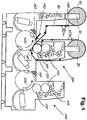
- Figure 4 now shows a schematic representation of a printing machine with a film transfer module for cold foil transfer, with a printing machine which processes individual printed sheets and which consists of at least two printing units.
- the two printing units are used for the following purposes:
- a printed sheet to be coated is provided with a pattern of cold glue.
- the cold adhesive is applied in a device configured as a printing station 100, e.g. B. a conventional printing unit of an offset printing machine via existing inking and dampening units 110, a printing plate on a plate cylinder 120, a printing cylinder 130 covered with a rubber blanket and an impression cylinder 400 '.
- Printing units in the form of flexographic printing units or coating units can also be used here.
- a transfer film 40 is passed through a transfer gap 60, the transfer film 40 being pressed against the print sheet in the transfer gap 60.
- a film transfer module 200 is used, which can correspond to a printing unit or a lacquer module or a base unit or a different processing station of a sheet-fed offset printing machine.
- the transfer gap 60 in the film transfer module 200 is formed by a roller 300 and a counter-pressure roller 400.
- the roller 300 can be a The blanket cylinder and the impression roller 400 correspond to an impression cylinder of an offset printing unit known per se.
- the roller 300 can correspond to a forme cylinder and the impression roller 400 to an impression cylinder of a coating module of a sheet-fed printing press.
- a so-called calendering unit can be provided downstream of the film transfer module 200 if the coated printing sheet is to be rolled over under increased pressure to increase the adhesion of the coating or to increase the smoothness and gloss of the printing sheet.
- a web guide for transfer foils 40 is shown within the foil transfer module 200 used for foil transfer.
- the film supply roll 80 is assigned to the film transfer module 200 on the sheet feed side.
- the film supply roll 80 has a rotary drive 70.
- the rotary drive 70 is required for the continuous, regulated supply of the transfer film 40 to the film transfer module 200 and is therefore controllable.
- guide devices 140 such as deflection or tensioning rollers, pneumatically actuated guide means, guide plates and the like are provided. In this way, the transfer film 40 can be guided flatly without distortion and kept in constant tension with respect to the roller 300.
- the guide devices 140 can also contain aids for introducing the transfer film 40. Automatic feeding aids for the transfer film 40 can also be used here.
- the transfer film 40 can in this case be guided around the roller 300, the transfer film 40 advantageously only being able to be fed in and removed from the transfer gap 60 from one side of the film transfer module 200 (see dashed line illustration).
- the transfer film 40 can differ from the illustration according to FIG Fig. 4 and depending on the available space, they can also be guided closely parallel to one another on one side of the film transfer module 200 in an advantageous manner in the infeed strand and in the outfeed strand.
- the transfer film 40 can also be fed in and removed from the transfer nip 60 essentially tangentially past the roller 300 or only wrapping around it at a small circumferential angle.
- the transfer film 40 is fed in from one side of the film transfer module 200 and removed to the opposite side of the film transfer module 200.
- a film collecting roll 90 is shown on the outlet side of the printing unit.
- the used transfer film material is wound up again on the film collecting roll 90.
- a rotary drive 70 which can be controlled, is also to be provided here. Essentially, the transfer film 40 could also be moved by the rotary drive 70 on the outlet side and held taut on the inlet side by means of a brake.
- the surface of the roller 300 i.e. the blanket cylinder or forme cylinder, is equipped with a compressible, damping element.
- the roller 300 is therefore provided with a covering 320 or with a corresponding coating.
- the covering 320 or the coating can be designed, for example, as a plastic cover, for example in the form of a rubber blanket or printing blanket.
- a clothing 320 is held on the roller 300 in a cylinder channel on tensioning devices.
- the covering 320 can be equipped with targeted elasticity in order to improve the transfer properties in the transfer gap 60. This can optionally act in a compressible intermediate layer. This compressibility is preferably similar to or less than in conventional rubber blankets or printing blankets, which are often used at this point. The compressibility mentioned can be achieved by means of a conventional compressible printing blanket. Combined coverings made from a hard printing blanket and a soft pad can also be used.
- the foil advance of the transfer foil 40 from the foil supply roll 80 to the transfer nip 60 and to the foil collecting roll 90 can be controlled in such a way that the transfer foil 40 is stopped as far as possible if the transfer layer 41 is not to be transferred.
- the transfer film 40 can be controlled in such a way that the film feed is stopped when the grippers pass through the receiving cylinder channel of the sheet-guiding counterpressure roller 400.
- the grippers hold a printed sheet on the counterpressure roller 400.
- the roller 300 has a corresponding cylinder channel in which the clothing 320 is held. In the area of the corresponding cylinder channels, there is no compression of the transfer film 40 between the roller 300 (blanket cylinder) and the counter-pressure roller 400.
- the roller 300 then continues to slide on the transfer film 40, while the transfer film 40 is stretched freely between the roller 300 and the counter-pressure roller 400 is. This state continues until the cylinder channel ends at the so-called start of printing and the transfer film 40 is again clamped between the roller 300 and the counter-pressure roller 400 with the inclusion of a printing sheet.
- the transfer film 40 is then transported further.
- the timing of the transfer film advance can start or stop a little earlier than the channel edges of the cylinder channel, depending on the necessary acceleration or braking of the film supply roll 80 or film collecting roll 90.
- dancer rollers 180 As exemplified in Figure 5 are shown, the control of the rotary drives 70 of the film supply rolls 80 or film collecting roll 90 may not be necessary.
- the necessary transfer film tension is also maintained by means of the dancer rollers 180.
- a further improvement in the utilization of the transfer film results from the fact that the transfer film 40 is divided into one or more partial film webs of smaller width. With appropriate control with the aid of the device or devices for clocking the film advance of each of the partial film webs, the utilization of the transfer film 40 can be improved even in the case of coating areas of different length within a printing sheet.
- each partial film web is only conveyed further in precisely the area in which the transfer layer 41 is to be applied. In the areas that are not to be coated, each partial film web can be shut down independently of the other partial film webs, so that no unnecessary film consumption occurs.
- dryers 160 are provided in the area of the cold adhesive application and in the area of the foil application.
- the cold adhesive applied in a pattern, in particular UV adhesive can be predried by means of a first dryer 160, so that the transfer layer 41 adheres better to the transfer film 40 and the carrier film 42 (see FIG Figure 1 ) can be peeled off before the cold adhesive hardens.
- the adhesion of the embossed transfer layer 41 on a printed sheet can subsequently be improved by means of a second dryer 160 by additionally accelerating the drying and curing of the cold adhesive.
- the quality of the coating of a printed sheet with a transfer layer is checked by means of an inspection or monitoring device 170 after the film has been applied.
- the inspection device 170 is directed to a sheet-guiding surface of the film transfer module 200 after the transfer nip 60 and possibly sealed off from the dryer 160 or to a sheet-guiding surface of a further sheet-guiding module downstream of the film transfer module 200.
- the coated print sheet passing there can thus be checked for completeness and quality of the coating.
- Print sheets identified as defective can be marked or sorted out as waste in a sorting device.
- the film transfer module 200 can be provided with devices for conditioning the transfer film 40 in order to improve the layer transfer and the coating result.
- the transfer film 40 can be influenced by means of the film guide device 140.
- the transfer layer 41 is applied to a printed sheet, in particular by means of a UV adhesive.
- a UV dryer is to be arranged after the printing station 100 for pre-drying the cold adhesive application and / or after the transfer of the transfer layer 41 in the film transfer module 200, a UV dryer penetrating the transfer layer 41, for example on the counter-pressure roller 400 of the film transfer unit 200.
- Embossings or reliefs are advantageously applied to the surface that has already been coated. This can take place, for example, in an embossing unit connected downstream of the film transfer module 200.
- the printed sheet is guided, for example, over a profiled surface and under pressure against a soft opposing surface.
- the embossing can also be carried out from the top, i.e. the coated side of the printing sheet, against an elastic base.
- the required device can be arranged in a printing unit or a film transfer module.
- the embossing or relief form is arranged on a blanket or forme cylinder or on the counter-pressure roller 400.
- the soft or elastic counter surface is arranged accordingly on the respective other cylinder of the printing unit or coating module.
- the transfer layer 41 can also be used to transfer special image elements.
- the permanent dampening is set to "Off" in the printing unit 100 in order to apply a cold adhesive, in particular a UV-crosslinking adhesive, to a printed sheet.
- a cold adhesive in particular a UV-crosslinking adhesive
- the rubber blanket on the impression cylinder 130 which transfers cold adhesive to a printing sheet, is only moistened with water at the points where there is no cold adhesive when printing. In this way, water absorption by the cold adhesive, which leads to emulsification of water and adhesive and furthermore a loss of the adhesive properties of the cold adhesive, can be reliably avoided.
- the abrasion was thus negligible and the adhesion of the transfer layer to the substrate / printed sheet was good.
Landscapes
- Decoration By Transfer Pictures (AREA)
- Laminated Bodies (AREA)
Claims (2)
- Procédé de transfert de films à froid, où une colle à froid (11), en particulier une colle de réticulation sous l'action d'un rayonnement UV, est appliquée sur un substrat (51) et est reliée à une strate de transfert (41) d'un film de transfert (40),
caractérisé en ce
qu'est assemblé au substrat (51) un film de transfert (40), lequel comprend un film de support (42) et une strate de transfert (41) pouvant être détachée du film de support (42), dans lequel la strate de transfert (41) comprend en partant du film de support (42) une couche à décoller transparente (43), une couche de vernis protecteur (44) transparente optionnelle, au moins une couche décorative (45) et au moins une couche d'apprêt (46) composée d'une colle thermoplastique, qui peut être activée dans une plage de températures > 90 °C, dans lequel lors du regroupement du film de transfert (40) avec le substrat (51), l'au moins une couche d'apprêt (46) du film de transfert (40) pointe vers la colle à froid (11), et dans lequel en outre la colle à froid (11) est durcie, en particulier la colle de réticulation sous l'action d'un rayonnement UV est irradiée et réticulée, dans lequel une liaison par collage à la strate de transfert (41) du film de transfert (40) est réalisée. - Procédé de transfert de films à froid selon la revendication 1,
caractérisé en ce
que la colle à froid (11), en particulier la colle de réticulation sous l'action d'un rayonnement UV, est appliquée sur le substrat (51) en une quantité d'application dans la plage de 1 à 3 g/m2.
Priority Applications (1)
| Application Number | Priority Date | Filing Date | Title |
|---|---|---|---|
| PL18196930T PL3441234T3 (pl) | 2008-09-12 | 2009-09-11 | Sposób transferu folii na zimno |
Applications Claiming Priority (2)
| Application Number | Priority Date | Filing Date | Title |
|---|---|---|---|
| DE102008047095A DE102008047095A1 (de) | 2008-09-12 | 2008-09-12 | Transferfolie zur Verwendung in einem Kaltfolientransferverfahren |
| EP09011629.4A EP2172347B1 (fr) | 2008-09-12 | 2009-09-11 | Film de transfert et procédé de transfert de films à froid |
Related Parent Applications (2)
| Application Number | Title | Priority Date | Filing Date |
|---|---|---|---|
| EP09011629.4A Division-Into EP2172347B1 (fr) | 2008-09-12 | 2009-09-11 | Film de transfert et procédé de transfert de films à froid |
| EP09011629.4A Division EP2172347B1 (fr) | 2008-09-12 | 2009-09-11 | Film de transfert et procédé de transfert de films à froid |
Publications (2)
| Publication Number | Publication Date |
|---|---|
| EP3441234A1 EP3441234A1 (fr) | 2019-02-13 |
| EP3441234B1 true EP3441234B1 (fr) | 2021-12-22 |
Family
ID=41667796
Family Applications (2)
| Application Number | Title | Priority Date | Filing Date |
|---|---|---|---|
| EP09011629.4A Active EP2172347B1 (fr) | 2008-09-12 | 2009-09-11 | Film de transfert et procédé de transfert de films à froid |
| EP18196930.4A Active EP3441234B1 (fr) | 2008-09-12 | 2009-09-11 | Procédé de transfert de films à froid |
Family Applications Before (1)
| Application Number | Title | Priority Date | Filing Date |
|---|---|---|---|
| EP09011629.4A Active EP2172347B1 (fr) | 2008-09-12 | 2009-09-11 | Film de transfert et procédé de transfert de films à froid |
Country Status (4)
| Country | Link |
|---|---|
| EP (2) | EP2172347B1 (fr) |
| DE (1) | DE102008047095A1 (fr) |
| PL (2) | PL3441234T3 (fr) |
| TR (1) | TR201900866T4 (fr) |
Families Citing this family (19)
| Publication number | Priority date | Publication date | Assignee | Title |
|---|---|---|---|---|
| US20120003433A1 (en) * | 2010-07-01 | 2012-01-05 | Sipix Chemical Inc. | Decoration film, decoration device, and method for manufacturing decoration device |
| DE102012105342A1 (de) * | 2012-06-20 | 2013-12-24 | Kba-Notasys Sa | Verfahren zum Übertragen eines Dekorabschnitts einer Prägefolie |
| DE102013012018A1 (de) * | 2013-07-19 | 2015-01-22 | X-Label Gmbh | Transferdruckverfahren |
| CN103419538B (zh) * | 2013-07-23 | 2016-12-28 | 霍浩麟 | 一种把pet聚酯转印膜转印到金属板材的生产工艺 |
| CN103612535B (zh) * | 2013-11-26 | 2016-01-06 | 李龙秀 | 一种仿金属浮雕烫印装饰板的制作工艺 |
| JP6439798B2 (ja) * | 2014-07-25 | 2018-12-19 | コニカミノルタ株式会社 | 箔画像形成方法 |
| JP6658175B2 (ja) * | 2015-03-23 | 2020-03-04 | 大日本印刷株式会社 | 転写箔 |
| CN107531042B (zh) * | 2015-03-23 | 2020-10-16 | 雷恩哈德库兹基金两合公司 | 用于施用箔的方法、施用设备和印刷设备 |
| TWI764875B (zh) * | 2015-11-03 | 2022-05-21 | 德商利昂哈德 庫爾茲公司 | 用於將薄膜上的轉印層施覆在底材上的方法及其施覆裝置 |
| DE102018105735A1 (de) | 2018-03-13 | 2019-09-19 | Mitsubishi Polyester Film Gmbh | Trennfolie für Tiefdruckanwendung |
| DE102018123471B4 (de) * | 2018-09-24 | 2021-09-23 | Formatic Gmbh | Verfahren und Vorrichtung zum Bedrucken von Oberflächen |
| CN113165407A (zh) * | 2018-12-12 | 2021-07-23 | 3M创新有限公司 | 由喷墨印刷粘合剂而制造的可剥离制品 |
| DE102019115530A1 (de) * | 2019-06-07 | 2020-12-10 | Leonhard Kurz Stiftung & Co. Kg | Verfahren, Vorrichtung und Körper |
| DE102019119535A1 (de) * | 2019-07-18 | 2021-01-21 | Leonhard Kurz Stiftung & Co. Kg | Verfahren und Vorrichtung zum Übertragen einer Transferlage einer Transferfolie auf ein Substrat |
| DE102019127734A1 (de) * | 2019-10-15 | 2021-04-15 | Leonhard Kurz Stiftung & Co. Kg | Transferfolie, Bauteil sowie Verfahren zu deren Herstellung |
| DE102019132787A1 (de) * | 2019-12-03 | 2021-06-10 | Leonhard Kurz Stiftung & Co. Kg | Dekorfolie, Verfahren zur Herstellung einer Dekorfolie und Verfahren zur Dekoration eines Zielsubstrats |
| DE102020129632A1 (de) | 2020-11-10 | 2022-05-12 | Illinois Tool Works Inc. | Verfahren und vorrichtung zum bearbeiten und insbesondere veredeln von druckobjekten |
| CN118181982A (zh) * | 2022-12-12 | 2024-06-14 | 库尔兹压烫科技(合肥)有限公司 | 转移膜、用于制造转移膜的方法和用于回收转移膜的方法 |
| CN120755063A (zh) * | 2025-05-30 | 2025-10-10 | 浙江是科新材料有限公司 | 一种用于柔性基材的可转移的复合涂层的制备及应用 |
Family Cites Families (20)
| Publication number | Priority date | Publication date | Assignee | Title |
|---|---|---|---|---|
| US3726710A (en) * | 1970-09-02 | 1973-04-10 | Union Carbide Corp | Silicon paper release compositions |
| US4454179A (en) * | 1982-05-10 | 1984-06-12 | Minnesota Mining And Manufacturing Company | Dry transfer article |
| US4557964A (en) * | 1983-06-06 | 1985-12-10 | Dennison Manufacturing Company | Heat transferable laminate |
| US4536434A (en) * | 1983-10-20 | 1985-08-20 | Dennison Manufacturing Co. | Heat transfer laminate |
| US4759968A (en) * | 1986-04-01 | 1988-07-26 | Minnesota Mining And Manufacturing Company | Transfer graphic article |
| DE4021908C2 (de) * | 1990-07-10 | 2002-04-25 | Gao Ges Automation Org | Verfahren zur Herstellung eines Substrats mit einem optisch variablen Element und Verwendung des Substrats |
| DE4110801C1 (fr) | 1991-04-04 | 1992-05-27 | Kurt 4040 Neuss De Lappe | |
| CA2132679C (fr) * | 1993-09-24 | 2006-11-28 | Donald R. Dressler | Support pour graphiques et lettrages decoratifs |
| US6146485A (en) * | 1997-01-30 | 2000-11-14 | Leonhard Kurz Gmbh & Co. | Method for making a decorative film with hot melt adhesive layer |
| US7344769B1 (en) * | 2000-07-24 | 2008-03-18 | High Voltage Graphics, Inc. | Flocked transfer and article of manufacture including the flocked transfer |
| JP2005501761A (ja) * | 2001-09-05 | 2005-01-20 | エーピーアイ・フォイルズ・リミテッド | 金型を用いない箔押し |
| JP3691030B2 (ja) * | 2002-07-01 | 2005-08-31 | 大日本インキ化学工業株式会社 | 水圧転写用フィルム及びそれを用いた水圧転写体の製造方法 |
| US20040023019A1 (en) * | 2002-08-02 | 2004-02-05 | 3M Innovative Properties Company | Particulate transfer film with improved bead carrier |
| DE10236959B4 (de) * | 2002-08-13 | 2004-10-07 | Leonhard Kurz Gmbh & Co. Kg | Mehrschichtfolie für den Bau von Skiern |
| JP2006507962A (ja) * | 2002-12-02 | 2006-03-09 | エイベリィ デニスン コーポレイション | 布にラベル付けする方法及びその方法に適した熱転写ラベル |
| GB0301091D0 (en) * | 2003-01-17 | 2003-02-19 | Mabbott Robert J | Provision of images on surfaces |
| DE10349963A1 (de) | 2003-10-24 | 2005-06-02 | Leonhard Kurz Gmbh & Co. Kg | Verfahren zur Herstellung einer Folie |
| US7396800B2 (en) * | 2004-07-27 | 2008-07-08 | E. I. Du Pont De Nemours And Company | Film ink support media and sublimation decoration process |
| DE102006033926A1 (de) | 2006-07-21 | 2008-01-24 | Man Roland Druckmaschinen Ag | Beschichten mittels einer Prägeeinrichtung |
| WO2008091148A2 (fr) * | 2007-01-23 | 2008-07-31 | F.T. Niemeijer Beheer B.V. | Décalcomanies décoratives améliorées et procédés et utilisations associés |
-
2008
- 2008-09-12 DE DE102008047095A patent/DE102008047095A1/de active Pending
-
2009
- 2009-09-11 PL PL18196930T patent/PL3441234T3/pl unknown
- 2009-09-11 EP EP09011629.4A patent/EP2172347B1/fr active Active
- 2009-09-11 EP EP18196930.4A patent/EP3441234B1/fr active Active
- 2009-09-11 TR TR2019/00866T patent/TR201900866T4/tr unknown
- 2009-09-11 PL PL09011629T patent/PL2172347T3/pl unknown
Also Published As
| Publication number | Publication date |
|---|---|
| EP2172347B1 (fr) | 2018-11-14 |
| PL2172347T3 (pl) | 2019-04-30 |
| EP2172347A3 (fr) | 2012-07-11 |
| EP2172347A2 (fr) | 2010-04-07 |
| PL3441234T3 (pl) | 2022-04-04 |
| EP3441234A1 (fr) | 2019-02-13 |
| DE102008047095A1 (de) | 2010-03-18 |
| TR201900866T4 (tr) | 2019-02-21 |
Similar Documents
| Publication | Publication Date | Title |
|---|---|---|
| EP3441234B1 (fr) | Procédé de transfert de films à froid | |
| EP2938496B1 (fr) | Procédé et dispositif d'estampage à froid sur des objets tridimensionnels | |
| EP1737658B1 (fr) | Procede d'application de film | |
| EP3370973B1 (fr) | Rocédé d'application permettant d'appliquer une couche de transfert d'un film sur un substrat | |
| EP3287296B1 (fr) | Procédé et dispositif d'estampage à chaud | |
| EP1839903A2 (fr) | Revêtement en relief d'imprégnation pour matière d'impression métallique | |
| EP2382095B1 (fr) | Fonctionnement d'une unité pour film à froid pourvue d'un groupe d'impression | |
| EP2004409A1 (fr) | Machine d'impression dotee d'un dispositif de gaufrage | |
| EP1737665A1 (fr) | Dispositif de matriçage | |
| EP1803562A1 (fr) | Dispositif de gaufrage pour l'enduction de feuilles à imprimer | |
| EP2163394A1 (fr) | Blanchet d'impression pour un procédé de transfert de films à froid | |
| EP1880848A2 (fr) | Dispositif et méthode de transfert à l'aide d'un dispositif de matriçage | |
| EP1700692B1 (fr) | Dispositif de transmission de couches imagées d'un film de support à de feuilles d'impression | |
| DE102010028545B4 (de) | Anschlagloser Folientransfer | |
| EP1798033A2 (fr) | Laminage avec un dispositif de gaufrage | |
| DE102008055141A1 (de) | Betrieb eines Kaltfolienaggregates mit einem Druckwerk | |
| EP1674260B1 (fr) | Procédé de transfert | |
| EP1700695A2 (fr) | Dispositif de gaufrage pour la garantie de produit dans une machine à imprimer à feuilles et procédé associé | |
| DE10249131B4 (de) | Selbstklebendes Material mit bedruckbaren Weißflächen, sowie Verfahren zu dessen Herstellung | |
| EP1700694A2 (fr) | Procédé de gaufrage pour carton ondulé dans une machine à imprimer en feuilles et dispositif associé | |
| EP1700693A2 (fr) | Procédé de gaufrage et dispositif associé pour matériaux d'imprimage aves surface structurée dans une machine à imprimer en feuilles |
Legal Events
| Date | Code | Title | Description |
|---|---|---|---|
| PUAI | Public reference made under article 153(3) epc to a published international application that has entered the european phase |
Free format text: ORIGINAL CODE: 0009012 |
|
| STAA | Information on the status of an ep patent application or granted ep patent |
Free format text: STATUS: REQUEST FOR EXAMINATION WAS MADE |
|
| 17P | Request for examination filed |
Effective date: 20180926 |
|
| AC | Divisional application: reference to earlier application |
Ref document number: 2172347 Country of ref document: EP Kind code of ref document: P |
|
| AK | Designated contracting states |
Kind code of ref document: A1 Designated state(s): AT BE BG CH CY CZ DE DK EE ES FI FR GB GR HR HU IE IS IT LI LT LU LV MC MK MT NL NO PL PT RO SE SI SK SM TR |
|
| GRAP | Despatch of communication of intention to grant a patent |
Free format text: ORIGINAL CODE: EPIDOSNIGR1 |
|
| STAA | Information on the status of an ep patent application or granted ep patent |
Free format text: STATUS: GRANT OF PATENT IS INTENDED |
|
| GRAJ | Information related to disapproval of communication of intention to grant by the applicant or resumption of examination proceedings by the epo deleted |
Free format text: ORIGINAL CODE: EPIDOSDIGR1 |
|
| GRAP | Despatch of communication of intention to grant a patent |
Free format text: ORIGINAL CODE: EPIDOSNIGR1 |
|
| INTG | Intention to grant announced |
Effective date: 20211014 |
|
| GRAS | Grant fee paid |
Free format text: ORIGINAL CODE: EPIDOSNIGR3 |
|
| GRAA | (expected) grant |
Free format text: ORIGINAL CODE: 0009210 |
|
| STAA | Information on the status of an ep patent application or granted ep patent |
Free format text: STATUS: THE PATENT HAS BEEN GRANTED |
|
| INTG | Intention to grant announced |
Effective date: 20211027 |
|
| AC | Divisional application: reference to earlier application |
Ref document number: 2172347 Country of ref document: EP Kind code of ref document: P |
|
| AK | Designated contracting states |
Kind code of ref document: B1 Designated state(s): AT BE BG CH CY CZ DE DK EE ES FI FR GB GR HR HU IE IS IT LI LT LU LV MC MK MT NL NO PL PT RO SE SI SK SM TR |
|
| REG | Reference to a national code |
Ref country code: GB Ref legal event code: FG4D Free format text: NOT ENGLISH |
|
| REG | Reference to a national code |
Ref country code: CH Ref legal event code: EP |
|
| REG | Reference to a national code |
Ref country code: DE Ref legal event code: R096 Ref document number: 502009016412 Country of ref document: DE |
|
| REG | Reference to a national code |
Ref country code: AT Ref legal event code: REF Ref document number: 1456842 Country of ref document: AT Kind code of ref document: T Effective date: 20220115 |
|
| REG | Reference to a national code |
Ref country code: IE Ref legal event code: FG4D Free format text: LANGUAGE OF EP DOCUMENT: GERMAN |
|
| REG | Reference to a national code |
Ref country code: NL Ref legal event code: FP |
|
| REG | Reference to a national code |
Ref country code: LT Ref legal event code: MG9D |
|
| PG25 | Lapsed in a contracting state [announced via postgrant information from national office to epo] |
Ref country code: LT Free format text: LAPSE BECAUSE OF FAILURE TO SUBMIT A TRANSLATION OF THE DESCRIPTION OR TO PAY THE FEE WITHIN THE PRESCRIBED TIME-LIMIT Effective date: 20211222 Ref country code: FI Free format text: LAPSE BECAUSE OF FAILURE TO SUBMIT A TRANSLATION OF THE DESCRIPTION OR TO PAY THE FEE WITHIN THE PRESCRIBED TIME-LIMIT Effective date: 20211222 Ref country code: BG Free format text: LAPSE BECAUSE OF FAILURE TO SUBMIT A TRANSLATION OF THE DESCRIPTION OR TO PAY THE FEE WITHIN THE PRESCRIBED TIME-LIMIT Effective date: 20220322 |
|
| PG25 | Lapsed in a contracting state [announced via postgrant information from national office to epo] |
Ref country code: SE Free format text: LAPSE BECAUSE OF FAILURE TO SUBMIT A TRANSLATION OF THE DESCRIPTION OR TO PAY THE FEE WITHIN THE PRESCRIBED TIME-LIMIT Effective date: 20211222 Ref country code: NO Free format text: LAPSE BECAUSE OF FAILURE TO SUBMIT A TRANSLATION OF THE DESCRIPTION OR TO PAY THE FEE WITHIN THE PRESCRIBED TIME-LIMIT Effective date: 20220322 Ref country code: LV Free format text: LAPSE BECAUSE OF FAILURE TO SUBMIT A TRANSLATION OF THE DESCRIPTION OR TO PAY THE FEE WITHIN THE PRESCRIBED TIME-LIMIT Effective date: 20211222 Ref country code: HR Free format text: LAPSE BECAUSE OF FAILURE TO SUBMIT A TRANSLATION OF THE DESCRIPTION OR TO PAY THE FEE WITHIN THE PRESCRIBED TIME-LIMIT Effective date: 20211222 Ref country code: GR Free format text: LAPSE BECAUSE OF FAILURE TO SUBMIT A TRANSLATION OF THE DESCRIPTION OR TO PAY THE FEE WITHIN THE PRESCRIBED TIME-LIMIT Effective date: 20220323 |
|
| PG25 | Lapsed in a contracting state [announced via postgrant information from national office to epo] |
Ref country code: SM Free format text: LAPSE BECAUSE OF FAILURE TO SUBMIT A TRANSLATION OF THE DESCRIPTION OR TO PAY THE FEE WITHIN THE PRESCRIBED TIME-LIMIT Effective date: 20211222 Ref country code: SK Free format text: LAPSE BECAUSE OF FAILURE TO SUBMIT A TRANSLATION OF THE DESCRIPTION OR TO PAY THE FEE WITHIN THE PRESCRIBED TIME-LIMIT Effective date: 20211222 Ref country code: RO Free format text: LAPSE BECAUSE OF FAILURE TO SUBMIT A TRANSLATION OF THE DESCRIPTION OR TO PAY THE FEE WITHIN THE PRESCRIBED TIME-LIMIT Effective date: 20211222 Ref country code: PT Free format text: LAPSE BECAUSE OF FAILURE TO SUBMIT A TRANSLATION OF THE DESCRIPTION OR TO PAY THE FEE WITHIN THE PRESCRIBED TIME-LIMIT Effective date: 20220422 Ref country code: ES Free format text: LAPSE BECAUSE OF FAILURE TO SUBMIT A TRANSLATION OF THE DESCRIPTION OR TO PAY THE FEE WITHIN THE PRESCRIBED TIME-LIMIT Effective date: 20211222 Ref country code: EE Free format text: LAPSE BECAUSE OF FAILURE TO SUBMIT A TRANSLATION OF THE DESCRIPTION OR TO PAY THE FEE WITHIN THE PRESCRIBED TIME-LIMIT Effective date: 20211222 Ref country code: CZ Free format text: LAPSE BECAUSE OF FAILURE TO SUBMIT A TRANSLATION OF THE DESCRIPTION OR TO PAY THE FEE WITHIN THE PRESCRIBED TIME-LIMIT Effective date: 20211222 |
|
| REG | Reference to a national code |
Ref country code: DE Ref legal event code: R097 Ref document number: 502009016412 Country of ref document: DE |
|
| PG25 | Lapsed in a contracting state [announced via postgrant information from national office to epo] |
Ref country code: IS Free format text: LAPSE BECAUSE OF FAILURE TO SUBMIT A TRANSLATION OF THE DESCRIPTION OR TO PAY THE FEE WITHIN THE PRESCRIBED TIME-LIMIT Effective date: 20220422 |
|
| PLBE | No opposition filed within time limit |
Free format text: ORIGINAL CODE: 0009261 |
|
| STAA | Information on the status of an ep patent application or granted ep patent |
Free format text: STATUS: NO OPPOSITION FILED WITHIN TIME LIMIT |
|
| PG25 | Lapsed in a contracting state [announced via postgrant information from national office to epo] |
Ref country code: DK Free format text: LAPSE BECAUSE OF FAILURE TO SUBMIT A TRANSLATION OF THE DESCRIPTION OR TO PAY THE FEE WITHIN THE PRESCRIBED TIME-LIMIT Effective date: 20211222 |
|
| 26N | No opposition filed |
Effective date: 20220923 |
|
| PG25 | Lapsed in a contracting state [announced via postgrant information from national office to epo] |
Ref country code: SI Free format text: LAPSE BECAUSE OF FAILURE TO SUBMIT A TRANSLATION OF THE DESCRIPTION OR TO PAY THE FEE WITHIN THE PRESCRIBED TIME-LIMIT Effective date: 20211222 |
|
| PG25 | Lapsed in a contracting state [announced via postgrant information from national office to epo] |
Ref country code: MC Free format text: LAPSE BECAUSE OF FAILURE TO SUBMIT A TRANSLATION OF THE DESCRIPTION OR TO PAY THE FEE WITHIN THE PRESCRIBED TIME-LIMIT Effective date: 20211222 |
|
| PG25 | Lapsed in a contracting state [announced via postgrant information from national office to epo] |
Ref country code: LU Free format text: LAPSE BECAUSE OF NON-PAYMENT OF DUE FEES Effective date: 20220911 |
|
| PG25 | Lapsed in a contracting state [announced via postgrant information from national office to epo] |
Ref country code: IE Free format text: LAPSE BECAUSE OF NON-PAYMENT OF DUE FEES Effective date: 20220911 |
|
| PG25 | Lapsed in a contracting state [announced via postgrant information from national office to epo] |
Ref country code: HU Free format text: LAPSE BECAUSE OF FAILURE TO SUBMIT A TRANSLATION OF THE DESCRIPTION OR TO PAY THE FEE WITHIN THE PRESCRIBED TIME-LIMIT; INVALID AB INITIO Effective date: 20090911 |
|
| PG25 | Lapsed in a contracting state [announced via postgrant information from national office to epo] |
Ref country code: CY Free format text: LAPSE BECAUSE OF FAILURE TO SUBMIT A TRANSLATION OF THE DESCRIPTION OR TO PAY THE FEE WITHIN THE PRESCRIBED TIME-LIMIT Effective date: 20211222 |
|
| PG25 | Lapsed in a contracting state [announced via postgrant information from national office to epo] |
Ref country code: MK Free format text: LAPSE BECAUSE OF FAILURE TO SUBMIT A TRANSLATION OF THE DESCRIPTION OR TO PAY THE FEE WITHIN THE PRESCRIBED TIME-LIMIT Effective date: 20211222 |
|
| PG25 | Lapsed in a contracting state [announced via postgrant information from national office to epo] |
Ref country code: MT Free format text: LAPSE BECAUSE OF FAILURE TO SUBMIT A TRANSLATION OF THE DESCRIPTION OR TO PAY THE FEE WITHIN THE PRESCRIBED TIME-LIMIT Effective date: 20211222 |
|
| REG | Reference to a national code |
Ref country code: CH Ref legal event code: U11 Free format text: ST27 STATUS EVENT CODE: U-0-0-U10-U11 (AS PROVIDED BY THE NATIONAL OFFICE) Effective date: 20251001 |
|
| PGFP | Annual fee paid to national office [announced via postgrant information from national office to epo] |
Ref country code: PL Payment date: 20250730 Year of fee payment: 17 Ref country code: TR Payment date: 20250908 Year of fee payment: 17 Ref country code: NL Payment date: 20250922 Year of fee payment: 17 |
|
| PGFP | Annual fee paid to national office [announced via postgrant information from national office to epo] |
Ref country code: BE Payment date: 20250919 Year of fee payment: 17 Ref country code: GB Payment date: 20250923 Year of fee payment: 17 |
|
| PGFP | Annual fee paid to national office [announced via postgrant information from national office to epo] |
Ref country code: FR Payment date: 20250925 Year of fee payment: 17 Ref country code: AT Payment date: 20250918 Year of fee payment: 17 |
|
| PGFP | Annual fee paid to national office [announced via postgrant information from national office to epo] |
Ref country code: DE Payment date: 20250929 Year of fee payment: 17 |
|
| PGFP | Annual fee paid to national office [announced via postgrant information from national office to epo] |
Ref country code: IT Payment date: 20250930 Year of fee payment: 17 |
|
| PGFP | Annual fee paid to national office [announced via postgrant information from national office to epo] |
Ref country code: CH Payment date: 20251001 Year of fee payment: 17 |