EP3441224B1 - Système de roue dentée et dispositif capteur - Google Patents
Système de roue dentée et dispositif capteur Download PDFInfo
- Publication number
- EP3441224B1 EP3441224B1 EP18187485.0A EP18187485A EP3441224B1 EP 3441224 B1 EP3441224 B1 EP 3441224B1 EP 18187485 A EP18187485 A EP 18187485A EP 3441224 B1 EP3441224 B1 EP 3441224B1
- Authority
- EP
- European Patent Office
- Prior art keywords
- rotor
- auxiliary rotor
- gear
- rotational axis
- angle
- Prior art date
- Legal status (The legal status is an assumption and is not a legal conclusion. Google has not performed a legal analysis and makes no representation as to the accuracy of the status listed.)
- Active
Links
Images

Classifications
-
- F—MECHANICAL ENGINEERING; LIGHTING; HEATING; WEAPONS; BLASTING
- F16—ENGINEERING ELEMENTS AND UNITS; GENERAL MEASURES FOR PRODUCING AND MAINTAINING EFFECTIVE FUNCTIONING OF MACHINES OR INSTALLATIONS; THERMAL INSULATION IN GENERAL
- F16H—GEARING
- F16H55/00—Elements with teeth or friction surfaces for conveying motion; Worms, pulleys or sheaves for gearing mechanisms
- F16H55/02—Toothed members; Worms
- F16H55/17—Toothed wheels
- F16H55/18—Special devices for taking up backlash
-
- B—PERFORMING OPERATIONS; TRANSPORTING
- B41—PRINTING; LINING MACHINES; TYPEWRITERS; STAMPS
- B41F—PRINTING MACHINES OR PRESSES
- B41F13/00—Common details of rotary presses or machines
- B41F13/008—Mechanical features of drives, e.g. gears, clutches
- B41F13/012—Taking-up backlash
Definitions
- the present invention relates to a gear arrangement for detecting and / or transmitting an angle of rotation of a rotatable shaft, preferably for a sensor device for detecting an angle of rotation of a rotatable shaft, in particular for a steering angle sensor device for detecting an angle of rotation of a steering shaft of a motor vehicle, wherein the gear arrangement is at least one rotationally synchronous with the shaft connectable and rotatable about a first axis of rotation main rotor with a toothing and at least one mechanically coupled with a constant and uniform first gear ratio with the main rotor and rotatable about a second axis of rotation, in particular parallel to the first axis of rotation, with a toothing, the toothing of the main rotor meshes with the teeth of the secondary rotor.
- the invention also relates to a sensor device for detecting an angle of rotation of a rotatable shaft, in particular a steering angle sensor device for detecting an angle of rotation of a steering shaft of a motor vehicle with an aforementioned gear arrangement and a sensor device for detecting the angle of rotation of the at least one auxiliary rotor.
- Gear arrangements of this type in particular for steering angle sensor devices, are known in principle from the prior art.
- gear arrangements are known, for example from DE 195 06 938 A1 or the DE 10 2009 031 176 A1 which, for the detection of an absolute angle of rotation of a shaft, additionally have a second secondary rotor mechanically coupled to the main rotor with a constant and uniform second translation that differs from the first translation, and a first sensor device assigned to the first secondary rotor for generating a sensor device that is dependent on a rotation angle of the first secondary rotor first sensor signal and a second sensor device assigned to the second secondary rotor for generating a second sensor signal that is dependent on an angle of rotation of the second secondary rotor.
- gear arrangements are known, for example from DE 195 06 938 A1 or the DE 10 2009 031 176 A1 which, for the detection of an absolute angle of rotation of a shaft, additionally have a second secondary rotor mechanically coupled to the main rotor with a constant and uniform second translation that differs from the
- the DE 10 2004 008 171 A1 discloses a gear arrangement in which a first gear of a secondary rotor is coupled in a rotationally fixed manner to an axis of rotation.
- a second gear wheel of the auxiliary rotor of the D1 is coupled to the axis of rotation via a spring element.
- the JP H09 89084 A discloses a gear arrangement with two gears which are braced with one another via an annular spring, a curved leg spring or a helical spring.
- the US 7 752 937 B1 discloses a gear arrangement with two gearwheels which are braced with one another via three finger-shaped spring elements which are arranged uniformly in the circumferential direction on a gearwheel and which engage in a central receptacle.
- the U.S. 2,966,806 A discloses a gear with two spring elements consisting of two curved spring arms which each extend from a central receptacle of the gear.
- the EP 0 849 078 A discloses a device for preventing backlash between a first gear and a second gear comprising an auxiliary gear which is rotatably mounted next to the first gear and rotates about the same axis of rotation as the first gear, the teeth of the auxiliary gear with the teeth of the mesh with the second gear.
- the device further comprises a leaf spring arrangement which extends essentially radially with respect to the axis of rotation of the first gearwheel. The leaf spring arrangement is deflected from its zero position and makes contact with a support element, the support element being acted upon with a force which pretensions the adjacent gearwheel and the first gearwheel.
- the U.S. 3,035,454 A discloses a gear arrangement in which a first gear of a secondary rotor is coupled in a rotationally fixed manner to an axis of rotation.
- a second gear wheel of the auxiliary rotor of the D1 is coupled to the axis of rotation via a spring element.
- Associated methods for detecting the absolute angle of rotation of the shaft with such a steering angle sensor device are also known in principle, for example from the former DE 195 06 938 A1 or the DE 101 10 785 A1 , to which reference is made in particular for more detailed explanations with regard to the detection of the absolute angle of rotation of the shaft, in particular as a function of two sensor signals.
- gear drives are often used, i.e. the main rotor and secondary rotor (s) are often gear wheels.
- the main rotor and secondary rotor (s) are often gear wheels.
- play can arise between the individual gears or a defined play can change in an undesirable manner.
- the individual gearwheels can become “braced” and, as a result, the gearwheel arrangement can be excessively worn.
- undesirable rattling noises can arise, especially if the game is increased in an undesired manner.
- a hysteresis can arise or an existing hysteresis can be increased. This can have a detrimental effect on the accuracy of the steering column module.
- a steering column module which has a stationary housing, a sleeve rotatably mounted in the housing and non-rotatably connected to a steering spindle with circumferential teeth and a gear that meshes with the teeth of the sleeve
- DE 10 2004 021 405 A1 propose to form the gearwheel by at least two superimposed gearwheel elements, which are braced against each other with the help of a leg spring or an ⁇ -shaped spring or are twisted against each other and each mesh with the toothing of the sleeve.
- an object of the invention to provide an alternative gear arrangement and an alternative sensor device, preferably an improved gear arrangement and an improved sensor device, in particular a gear arrangement, which enables an almost, in particular completely hysteresis-free transmission of a rotation angle of a shaft and which is particularly structurally effective has a simple structure.
- a gear arrangement for detecting and / or transmitting an angle of rotation of a rotatable shaft according to the present invention comprises the features of claim 1.
- the main rotor is preferably a gearwheel, in particular a gearwheel that can be arranged coaxially to the shaft and connected to the shaft in a rotationally fixed manner, the main rotor being arranged coaxially to the shaft and non-rotatably with the shaft in a functional state of use of a gear arrangement according to the invention, in particular in a functional state of use of a sensor device according to the invention connected is.
- a spring element in the sense of the present invention is a component that acts and / or is designed as a spring. “Coupled” means “operatively connected” in the context of the present invention. Two components that are coupled by means of a spring element are thus operatively connected in the sense of the present invention by means of a spring, in particular in such a way that a relative movement of the two components can be brought about at least partially against a restoring force of the spring.
- a spiral spring in the sense of the present invention is understood to mean a spring which is designed to be at least partially, in particular largely, preferably only, loaded in bending.
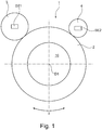
- a bending angle of a spiral spring that is straight in a stress-free state is understood to mean the outer angle ⁇ between the tangents of a fiber of the spiral spring that is neutral in the end points, as follows illustration 1 shown.
- a structurally particularly simple structure of a gear arrangement with a secondary rotor With a straight spiral spring with a bending angle of zero degrees, ie of 0 °, a structurally particularly simple structure of a gear arrangement with a secondary rotor, the at least two concentric to the second axis of rotation and parallel to each other in the axial direction of the second axis of rotation, in particular in the axial direction adjacent and / or adjacent to one another, having gears which are coupled to one another by means of a spring element can be achieved. Furthermore, the gearwheel arrangement can be assembled in a simple manner. In particular, a gear wheel arrangement that can be produced inexpensively can be provided.
- a backlash-free transmission of a rotary movement of the main rotor to the Secondary rotor can be achieved, in particular while avoiding or reducing the risk of distortion of the gear arrangement.
- a gear arrangement can be provided which enables backlash-free transmission of the rotary movement of the main rotor to the secondary rotor, in which, however, in particular at the same time, the risk of increased wear that may occur due to tension that occurs is reduced or avoided.
- the gear arrangement preferably enables a relative rotation of the two gears by a relative angle of rotation of at least 2, 3 or 4 degrees and / or of at most 3, 4 or 5 degrees, with the relative angle of rotation in the context of the invention being that angle in the circumferential direction by which one of the gears of the secondary rotor can be rotated relative to the other gear in the circumferential direction.
- the at least two gearwheels of the secondary rotor preferably have the same number of teeth and / or the same toothing geometry and / or in the area of the toothing at least partially, preferably completely, congruent, i.e. congruent, face cross-sections.
- all of the gears i.e. the gears of the main rotor and the secondary rotor, in particular the gears of the at least two gears of the secondary rotor, each have involute gearing.
- the toothing can, however, also be designed as Wildhaber-Novikov toothing or as cycloid toothing, the selection of the toothing being based in particular on the respective requirements of the toothing in the individual case.
- the involute toothing is particularly suitable for most applications.
- the gear wheel arrangement is preferably designed such that the teeth of the at least two gear wheels of the secondary rotor are congruent, ie congruent, one above the other at a relative angle of rotation of zero degrees (0 °).
- the spiral spring preferably has at least one spring leaf or is a leaf spring, the spiral spring in particular having an at least partially rectangular spring leaf and / or a spring leaf with an at least partially rectangular cross section.
- the spiral spring can also have several spring leaves, in particular a spring leaf package with several spring leaves stacked on top of one another.
- One or more spring leaves can also have a cross section deviating from a rectangular shape and / or a rectangular cross section.
- One or more spring leaves can, in particular, be trapezoidal or barrel-shaped and / or have a trapezoidal or barrel-shaped cross section.
- the spiral spring has at least one spring leaf or is a leaf spring
- at least one spring leaf, in particular the leaf spring is preferably arranged in such a way that, in a straight state, the spiral spring extends at least partially, preferably completely, its width in the axial direction parallel to the second axis of rotation and their thickness in the radial direction to the second axis of rotation.
- the spiral spring can also have at least one spring wire or be formed by a spring wire.
- the spiral spring is designed and arranged in such a way that by rotating the two gears of the secondary rotor relative to one another, the spiral spring can be bent with a bending radius lying in a plane normal to the second axis of rotation.
- the bending radius is the radius that defines the curvature of the bend.
- the spiral spring is designed and arranged in such a way that a rotation of the two gear wheels of the secondary rotor relative to one another causes a change in the bending of the spiral spring.
- At least a first of the gear wheels of the secondary rotor is non-rotatably connected to a secondary rotor shaft or rotatably mounted with respect to a stationary secondary rotor axis, while the other, at least second gear is mounted in particular rotatably on the first gear.
- both gearwheels can be connected to a secondary rotor shaft in a rotationally fixed manner separately from one another or to be mounted so as to be rotatable with respect to a stationary secondary rotor axis, different mounting also being possible.
- the first sleeve-shaped section of at least one gear wheel of the secondary rotor preferably the first sleeve-shaped section of the at least two gear wheels of the secondary rotor, has at least one recess in the circumferential direction, preferably two recesses opposite one another in the radial direction, in particular at least a slot and / or a groove through which the spiral spring extends.
- the spiral spring preferably extends in the radial direction through the recess (s), in particular with play, which is preferably dimensioned such that a defined, maximum possible twist angle is possible, but in particular always, ie in particular at every operating point, a sufficient Spring (tension) force can be built up in order to achieve a backlash-free toothing of the secondary rotor with the main rotor.
- the second sleeve-shaped section is preferably located radially further outward than the first sleeve-shaped section of the associated gearwheel.
- the spiral spring is fixed on at least one of the at least two gear wheels, in particular on the first gear wheel, preferably in the region of its ends or at its ends, in particular on the second sleeve-shaped section of the gear wheel.
- the spiral spring is preferably fixed by clamping on the associated gearwheel and / or connected to this gearwheel by injection-molding with a plastic, from which in particular the associated gearwheel is made.
- the spiral spring based on a functional installation state of the steering angle sensor device in the vehicle, is in which the second axis of rotation extends in particular parallel to an axis of rotation of the steering shaft and / or a steering column, preferably fixed on the lower gear, in particular by clamping.
- the spiral spring is guided and / or clamped in a slot and / or a groove on the other of the at least two gear wheels of the secondary rotor, in particular on the one on which it is not fixed, preferably on the second gear wheel, wherein the slot and / or the groove preferably extends at least partially along a diameter of the associated gearwheel, in particular only within the first sleeve-shaped section. That is, the slot and / or the groove for receiving and / or guiding and / or clamping the spiral spring on the second gear wheel preferably does not protrude in the radial direction beyond the first sleeve-shaped section.
- the spiral spring is preferably guided and / or clamped in a slot and / or a groove on the upper gear wheel in relation to a functional installation state of the steering angle sensor device in the vehicle.
- a U-shaped slot and / or groove cross-section has proven to be advantageous. However, geometries deviating therefrom are also conceivable.
- the groove can have clamping elements which can preferably extend laterally inward into the groove, in particular parallel to a radial plane of the gearwheel.
- a sensor device for detecting an angle of rotation of a rotatable shaft, in particular a steering angle sensor device according to the invention for detecting an angle of rotation of a steering shaft of a motor vehicle, has a gear arrangement with at least one main rotor, which can be connected to the shaft in a rotationally synchronous manner and rotates about a first axis of rotation, with a toothing and at least one mechanically with a constant and uniform first transmission coupled to the main rotor and rotatable about a second axis of rotation, in particular parallel to the first axis of rotation, with a toothing, the toothing of the main rotor meshing with the toothing of the secondary rotor. Furthermore, a The sensor device according to the invention has a sensor device for detecting the angle of rotation of the at least one secondary rotor.
- the gear wheel arrangement of a sensor device according to the invention is a gear wheel arrangement designed according to the present invention.
- a sensor device enables backlash-free transmission of the angle of rotation of the main rotor to at least one secondary rotor over a large operating range and thus an improvement in the accuracy of the sensor device.
- a sensor device can also have an evaluation device for detecting the angle of rotation of the shaft at least as a function of the detected angle of rotation of the secondary rotor. Furthermore, one or more further sensor devices can be present.
- the sensor device has at least one magnetic field generating device, in particular a permanent magnet, and at least one magnetic sensor, whereby a rotary movement of the secondary rotor and thus a rotary movement of the shaft can be transmitted to the magnetic sensor by means of the magnetic field generating device and a rotary angle can be transmitted by means of the magnetic sensor of the associated secondary rotor can be detected.
- the magnetic field generating device is preferably attached to the secondary rotor in a rotationally fixed manner, in particular to one of the gearwheels of the secondary rotor, preferably to the second gearwheel of the secondary rotor.
- the magnetic sensor is in particular arranged fixed to the housing.
- a sensor device preferably has a further, second secondary rotor which is mechanically coupled to the main rotor with a constant and uniform second transmission different from the first transmission, as well as a first sensor device assigned to the first secondary rotor for detecting the angle of rotation of the first secondary rotor and for generating one of a first sensor signal dependent on a rotation angle of the first auxiliary rotor and a further second sensor device assigned to the further, second auxiliary rotor for detecting a rotation angle of the second auxiliary rotor and for generating a second sensor signal dependent on a rotation angle of the second auxiliary rotor.
- the evaluation device is preferably designed to determine the angle of rotation, in particular to determine the absolute angle of rotation of the main rotor from the sensor signals of the sensor devices.
- the second secondary rotor is also designed according to the invention and has at least two gears that are concentric to a further axis of rotation and parallel to one another in the axial direction of the further axis of rotation, in particular adjacent and / or adjacent in the axial direction, which are each rotatable about the further axis of rotation and mesh with the toothing of the main rotor, the at least two gears of the second auxiliary rotor being rotatable relative to one another about the further axis of rotation and being coupled to one another by means of at least one further spring element, in particular by means of a straight spiral spring, which in a stress-free state has a bending angle of has zero degrees (0 °).
- Fig. 1 shows a schematic representation of the basic structure of an embodiment of a steering angle sensor device 1 according to the invention for detecting and determining an absolute steering angle ⁇ of a steering shaft 10 with an embodiment of a gear arrangement according to the invention in plan view.
- the steering angle sensor device 1 has a main rotor 2 connected to the steering shaft 10 in a rotationally fixed manner and without play in the circumferential direction, as well as a first secondary rotor 3 and a second secondary rotor 4.
- the main rotor 2 is connected to the steering shaft 10 in a rotationally synchronous manner due to its non-rotatable, circumferential backlash-free connection with the steering shaft 10, so that a rotation of the steering shaft 10 about a first axis of rotation D1 by a defined, absolute Rotation angle ⁇ causes a rotation of the main rotor 2 by the same, defined, absolute rotation angle ⁇ .
- the first secondary rotor 3 and the second secondary rotor 4 each form a gear transmission with the main rotor 2, the secondary rotor 3 being mechanically coupled to the main rotor 2 via a toothing with a constant and uniform first gear ratio to the main rotor 2.
- the second secondary rotor 4 is also mechanically coupled to the main rotor 2 via a toothing, but with a constant and uniform second transmission which is different from the first transmission.
- the second secondary rotor 4 has a number of teeth that differs from the first secondary rotor 3.
- the steering angle sensor device 1 To generate a first sensor signal dependent on an angle of rotation of the first auxiliary rotor 3, the steering angle sensor device 1 according to the invention has a first sensor device SE1 and a second sensor device SE2 for generating a second sensor signal dependent on an angle of rotation of the second auxiliary rotor 4.
- the steering angle sensor device 1 has an evaluation device (not shown here) for determining the absolute angle of rotation ⁇ of the main rotor 2 or the steering shaft 10 connected to it in a rotationally synchronous manner from the sensor signals of the sensor devices SE1 and SE2.
- the sensor devices SE1 and SE2 are designed as magnetic sensor devices SE1, SE2, the first sensor device SE1 and the second sensor device SE2 each being designed to measure the angle of rotation of the associated secondary rotor 3 and 4, respectively, at least via one to detect a full rotation, ie at least over a rotation angle range of 360 °, so that the absolute rotation angle ⁇ of the main rotor or the steering shaft 10 can be determined or determined from the recorded first sensor signal and / or from the recorded second sensor signal.
- the evaluation device of the steering angle sensor device 1 is designed to determine the absolute angle of rotation ⁇ of the main rotor 2 from the first sensor signal generated by the first sensor device SE1 and / or from the second sensor signal generated by the second sensor device SE2, in particular after the vernier principle, as it is in the DE 195 06 938 A1 is described, to which reference is expressly made at this point for the functionality.
- Fig. 2 shows a section of the steering angle sensor device 1 according to the invention in the area of the first secondary rotor 3 from Fig. 1 in detail in plan view, it being particularly easy to see in this illustration that the first secondary rotor 3 is coupled to the main rotor 2 via a toothing and meshes with it.
- the secondary rotor 3 has at least two gearwheels Z1 and Z2 which are concentric to a second axis of rotation D2 and in the axial direction of the second axis of rotation D2, in particular arranged one above the other, gearwheels Z1 and Z2, which are each rotatable about the second axis of rotation D2 and each with the toothing of the Main rotor 2 mesh, the at least two gears Z1 and Z2 of the secondary rotor 3 being rotatable or rotated relative to one another about the second axis of rotation D2 and having identically designed gears, ie the same number of teeth and the same tooth geometry.
- the second gear Z2 To detect the angle of rotation of the first auxiliary rotor 3, the second gear Z2, based on the illustration in FIG Fig. 2 A permanent magnet M is attached to the upper gear Z2 as a magnetic field generating device M, which together with a magnetic sensor not shown here, in particular a Hall sensor, is part of the first sensor device SE1, in particular together with the magnetic sensor forms the first sensor device SE1.
- a magnetic sensor not shown here in particular a Hall sensor
- Fig. 3 shows the first secondary rotor 3 of the steering angle sensor device according to the invention from FIG Fig. 1 and 2 in an exploded view with the spring element 5 provided according to the invention and designed as a straight spiral spring, which in a stress-free state has a bending angle ⁇ (cf. Fig. 1 ) of zero degrees (0 °), and via which the first gear Z1 and the second gear Z2 of the first secondary rotor 3 are coupled to one another.
- ⁇ cf. Fig. 1
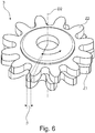
- the second, in this case upper, gear Z2 has a parallel to the second in the axial direction Axis of rotation D2 extending first sleeve-shaped section 6 for the rotatable attachment of the gear Z2 to a stationary, in particular housing-fixed, secondary rotor axis not shown in the figures.
- the first, in this case lower, gear Z1 also has a first sleeve-shaped section 8 extending in the axial direction parallel to the second axis of rotation D2, but not for the rotatable attachment of the gear Z1 to a stationary, in particular housing-fixed, secondary rotor axis not shown in the figures , but for rotatable attachment to the first sleeve-shaped section 6 of the second gear Z2.
- the two gears Z1 and Z2 each have a second, second sleeve-shaped section 7 or 9, each extending in the axial direction parallel to the second axis of rotation D2, which is located further out in the radial direction than the respective first sleeve-shaped section 6 or 8th.
- the first sleeve-shaped section 8 has two opposing recesses 11A and 11B in circumferential directions, in particular recesses 11A and 11B each designed as slots 11A and 11B, through which the spiral spring 5 extends, the spiral spring 5 being shown in a stress-free state.
- This exemplary embodiment of a gear wheel arrangement according to the invention is designed in such a way that the spiral spring 5 is in the tension-free state, as in FIG Fig. 4 shown, completely, ie extending over its entire length along a diameter of the secondary rotor 3 or along a diameter of the first gear Z1.
- the spiral spring 5 is also fixed on the first gear Z1, in this case in the region of its ends, the spiral spring 5 being clamped in particular on the second sleeve-shaped section 9 of the first gear Z1.
- the spiral spring 5 is formed in the present case by a rectangular spring leaf, ie a leaf spring 5, the spiral spring 5 being arranged vertically, ie vertically.
- the second sleeve-shaped section 9 of the first gear Z1 of the secondary rotor 3 also has two radially opposite recesses 12A and 12B in the circumferential direction, which in this case are not designed as slots, but as grooves 12A, 12B with a U-shaped cross section .
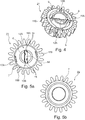
- the second gear Z2 has on its underside, as shown in FIG Figure 5a can be seen, which shows the second gear Z2 in a view from below, also two recesses 13A and 13B in the first sleeve-shaped section 6, which are opposite in the radial direction.
- the second gear Z2 for coupling with the spiral spring 5 or with the first gear Z1 by means of the spiral spring 5 has a Groove 14 which extends within the first sleeve-shaped section 6 of the second gear Z2 along a diameter of the second gear Z2.
- Figure 5b In comparison, shows a view of the second gear Z2 from above.
- the groove 14 of the second gear Z2 has four laterally inwardly projecting, alternately arranged, mushroom-shaped or dome-shaped projections 15 as clamping elements.
- the second sleeve-shaped section 7 of the second gear Z2 also has two radially opposite recesses 16A and 16B in the circumferential direction, which, however, extend over a significantly larger circumferential angle than the recesses 12A and 12B of the first gear in its second, sleeve-shaped section 9, the sleeve-shaped section 7 of the second gear Z2 being complementary or corresponding to the second sleeve-shaped section 9 of the first gear Z1 and in particular having two sections 17A and 17B arranged between the recesses 16A and 16B and acting as projections.
- the two second, sleeve-shaped sections 9 and 7 of the two gears Z1 and Z2 are designed in such a way that, when the gear arrangement is properly assembled, they are in engagement with one another in the manner of a claw clutch in a coupled, torque-transmitting condition.
- the present gear wheel arrangement is designed in such a way, in particular the spiral spring 5 is designed and arranged in such a way that, in a functional state of assembly, rotation of the two gears Z1 and Z2 of the secondary rotor 3 relative to one another causes the spiral spring 5 to bend in a plane normal to the second axis of rotation D2 lying bending radius can be effected.
- the gear arrangement is designed in such a way that, in a tension-free state of the spiral spring 5, the two gears Z1 and Z2 of the auxiliary rotor 3 are rotated relative to one another by a defined angle of rotation ⁇ according to Fig.
- the first gear Z1 and the second gear Z2 can be rotated against a spring force of the spiral spring 5 up to a rotation angle of zero degrees relative to each other, in particular up to the teeth of the first gear Z1 are congruent, ie congruent, with the teeth of the second gear Z2 completely on top of one another.
- the defined angle of rotation ⁇ which occurs in the tension-free state of the spiral spring 5, is 3.5 ° in this exemplary embodiment; depending on the application, 2 ° may also be sufficient or 5 ° may be required. That is, the recesses 12A, 12B or 16A, 16B and the groove 14 are dimensioned and arranged, in particular relative to one another, in such a way that a defined angle of rotation ⁇ of 3.5 ° is set in the tension-free state of the spiral spring 5.
- the tooth flanks of the teeth of the first gearwheel Z1 and the second gearwheel Z2 protrude slightly beyond one another in the circumferential direction or step back behind them.
- the tooth formed by the two gears Z1 and Z2 appears wider than the tooth of a single gear Z1 or Z2.
- the associated tooth gap of the main rotor 2 meshing with the respective gear wheels Z1 and Z2 can be filled better, in particular completely, ie without play.
- the two gears Z1 and Z2 are rotated relative to one another as a result of the forces that occur in such a way that the respective teeth increasingly overlap, in particular up to a maximum rotation angle of 0 °, ie until they are completely on top of each other, whereby tensioning of the toothing, which is usually associated with increased wear, can be avoided.
- a spiral spring 5 that is straight in the tension-free state enables a particularly simple construction of a gear arrangement and thus a particularly simple construction of a corresponding sensor device 1, in particular a steering angle sensor device 1 for detecting a rotation angle ⁇ of a steering shaft 10 of a motor vehicle.
- the exemplary embodiment shown and described of a steering angle sensor device 1 according to the invention is designed analogously to the secondary rotor 3. It differs only with regard to the geometrical dimensions, in particular with regard to the number of teeth and the associated diameter that concretizes the toothing (pitch circle, tip circle and root circle diameter) as well as with regard to the defined angle of rotation value that occurs when the spiral spring is free of tension, which in this case is 3 ° of the first secondary rotor 3.
- the second secondary rotor 4 also, in particular additionally, enables the rotation angle d of the main rotor 2 to be transmitted to the second secondary rotor 4 without play, the accuracy of the steering angle sensor device 1 can be improved even further.
Landscapes
- Engineering & Computer Science (AREA)
- Mechanical Engineering (AREA)
- General Engineering & Computer Science (AREA)
- Power Steering Mechanism (AREA)
Claims (7)
- Ensemble de roues dentées destiné à détecter ou transmettre un angle de rotation (δ) d'un arbre rotatif destiné à un dispositif de détection d'angle de braquage destiné à détecter un angle de rotation (δ) d'un arbre de direction (10) d'un véhicule automobile, ledit ensemble comportant :au moins un rotor principal rotatif (2) pourvu d'une denture, pouvant être relié de manière synchrone en rotation à l'arbre (10) et pouvant tourner sur un premier axe de rotation (D1),au moins un rotor secondaire (3, 4) pourvu d'une denture, accouplé mécaniquement au rotor principal (2) avec un premier rapport de transmission constant et uniforme et pouvant tourner sur un deuxième axe de rotation (D2) parallèle au premier axe de rotation (D1), etun élément à ressort (5),la denture du rotor principal (2) s'engrenant avec la denture du rotor secondaire (3, 4),le rotor secondaire (3, 4) comportant au moins deux roues dentées (Z1, Z2) qui sont concentriques au deuxième axe de rotation (D2) et parallèles l'une à l'autre dans la direction axiale du deuxième axe de rotation (D2) et qui peuvent chacune tourner sur le deuxième axe de rotation (D2) et s'engrener avec la denture du rotor principal (2),les au moins deux roues dentées (Z1, Z2) du rotor secondaire (3, 4) pouvant tourner l'une par rapport à l'autre sur le deuxième axe de rotation (D2), etles au moins deux roues dentées (Z1, Z2) du rotor secondaire (3, 4) étant accouplées l'une à l'autre au moyen d'un élément à ressort (5),l'élément à ressort (5) étant un ressort spiral droit (5) qui, dans un état sans contrainte, a un angle de flexion (α) de zéro degré,le ressort spiral (5) s'étendant dans au moins un état de fonctionnement de l'ensemble de roues dentées le long d'un diamètre du rotor secondaire (3),le ressort spiral (5) coupant le deuxième axe de rotation,caractérisé en ce quel'une au moins des deux roues dentées (Z2) du rotor secondaire (3, 4) comporte une première portion (6) en forme de manchon qui s'étend dans la direction axiale parallèlement au deuxième axe de rotation (D2) pour fixer solidairement en rotation la roue dentée (Z2) à un arbre de rotor secondaire pouvant tourner sur le deuxième axe de rotation (D2) ou pour fixer la roue dentée (Z2) de manière rotative à un axe de rotor secondaire fixe,l'une des deux roues dentées (Z1, Z2) du rotor secondaire (3, 4) comportant une deuxième portion (7, 9) en forme de manchon qui s'étend dans la direction axiale parallèlement au deuxième axe de rotation (D2), et la deuxième portion (7, 9) en forme de manchon d'au moins une roue dentée (Z1, Z2) du rotor secondaire (3, 4) comportant au moins deux évidements (12A, 12B ; 16A, 16B) opposés dans la direction radiale, etles deuxièmes portions (7, 9) en forme de manchon des au moins deux roues dentées (Z1, Z2) étant conçues de telle sorte que leurs deuxièmes portions (7, 9) en forme de manchon soient en engagement l'une avec l'autre à la manière d'un accouplement à griffes dans un état accouplé de transmission de couple, les évidements (12A, 12B ; 16A, 16B) étant dimensionnés et disposés dans la direction circonférentielle de telle sorte que, dans un état sans tension du ressort spiral (5), les au moins deux roues dentées (Z1, Z2) du rotor secondaire (3, 4) soient tournées l'une par rapport à l'autre de l'angle de rotation défini (β) et soient tournées l'une par rapport à l'autre jusqu'à un angle de rotation (β) de zéro degré en s'opposant à une force de rappel du ressort spiral (5).
- Ensemble de roues dentées selon l'une des revendications précédentes, caractérisé en ce que le ressort spiral (5) est conçu et disposé de telle sorte qu'une rotation des deux roues dentées (Z1, Z2) du rotor secondaire (3, 4) l'une par rapport à l'autre entraîne une flexion du ressort spiral (5) avec un rayon de flexion situé dans un plan normal au deuxième axe de rotation (D2).
- Ensemble de roues dentées selon l'une des revendications précédentes, caractérisé en ce que la première portion (6, 8) en forme de manchon d'au moins une roue dentée (Z1, Z2) du rotor secondaire (3, 4) au moins deux évidements (11A, 11B ; 13A, 13B) à travers lesquels s'étend le ressort spiral (5).
- Ensemble de roues dentées selon l'une des revendications précédentes, caractérisé en ce que le ressort spiral (5) est fixé à l'un au moins des au moins deux roues dentées (Z1) au niveau de leurs extrémités ou à leurs extrémités.
- Ensemble de roues dentées selon l'une des revendications précédentes, notamment selon la revendication 8, caractérisé en ce que le ressort spiral (5) est guidé ou est fixé dans une fente ou une gorge (14) ménagée au niveau de l'autre des au moins deux roues dentées (Z2) du rotor secondaire (3, 4), la fente ou la gorge (14) s'étendant au moins partiellement le long d'un diamètre de la roue dentée associée (Z2).
- Dispositif de détection d'angle de braquage (1) destiné à détecter un angle de rotation (δ) d'un arbre de direction (10) d'un véhicule automobile, ledit dispositif comportant :un ensemble de roues dentées comprenant au moins un rotor principal (2) pourvu d'une denture, pouvant être relié à l'arbre (10) d'une manière synchrone en rotation et pouvant tourner sur un premier axe de rotation (D1) et au moins un rotor secondaire (3, 4) pourvu d'une denture, accouplé mécaniquement au rotor principal (2) avec un premier rapport de transmission constant et uniforme et pouvant tourner sur un deuxième axe de rotation (D2) parallèle au premier axe de rotation (D1) et, la denture du rotor principal (2) s'engrenant avec la denture du rotor secondaire (3, 4), etun moyen de détection (SE1, SE2) destiné à détecter l'angle de rotation (δ) de l'au moins un rotor secondaire (3, 4),
caractérisé en ce quel'ensemble de roues dentées est conçu selon l'une des revendications 1 à 5. - Dispositif de détection (1) selon la revendication 6, caractérisé en ce que
le moyen de détection (SE1, SE2) comporte au moins un moyen de génération de champ magnétique (M) et au moins un capteur magnétique, un mouvement de rotation du rotor secondaire (3, 4) pouvant être transmis au capteur magnétique à l'aide du moyen de génération de champ magnétique (M) et un angle de rotation du rotor secondaire associé (3, 4) étant détecté au moyen du capteur magnétique.
Applications Claiming Priority (1)
| Application Number | Priority Date | Filing Date | Title |
|---|---|---|---|
| DE102017118373.6A DE102017118373A1 (de) | 2017-08-11 | 2017-08-11 | Zahnradanordnung und Sensorvorrichtung |
Publications (2)
| Publication Number | Publication Date |
|---|---|
| EP3441224A1 EP3441224A1 (fr) | 2019-02-13 |
| EP3441224B1 true EP3441224B1 (fr) | 2021-04-14 |
Family
ID=63165263
Family Applications (1)
| Application Number | Title | Priority Date | Filing Date |
|---|---|---|---|
| EP18187485.0A Active EP3441224B1 (fr) | 2017-08-11 | 2018-08-06 | Système de roue dentée et dispositif capteur |
Country Status (2)
| Country | Link |
|---|---|
| EP (1) | EP3441224B1 (fr) |
| DE (1) | DE102017118373A1 (fr) |
Families Citing this family (6)
| Publication number | Priority date | Publication date | Assignee | Title |
|---|---|---|---|---|
| DE102019201676A1 (de) * | 2019-02-08 | 2020-08-13 | Zf Friedrichshafen Ag | Anordnung Bestimmen eines Drehwinkels und elektrische Maschine |
| CN114518630B (zh) * | 2020-11-19 | 2023-09-01 | 成都极米科技股份有限公司 | 空回消除方法、装置、电子设备及计算机可读存储介质 |
| CN112648919B (zh) * | 2020-12-02 | 2025-02-25 | 北京红胡子机器人科技有限公司 | 旋转角度测量装置和多角度行驶车 |
| CN112683157B (zh) * | 2020-12-02 | 2025-10-28 | 北京红胡子机器人科技有限公司 | 旋转角度测量装置和多角度行驶车 |
| DE102022126015B3 (de) | 2022-10-07 | 2024-02-15 | Bcs Automotive Interface Solutions Gmbh | Zahnradanordnung für einen Sensor sowie Lenkwinkelsensor-Baugruppe |
| DE102024113690A1 (de) * | 2024-05-16 | 2025-11-20 | Valeo Schalter Und Sensoren Gmbh | Abgreifeinrichtung für eine Lenkwinkelerfassungseinrichtung für eine Schubstange eines Lenkgetriebes eines Fahrzeugs, Lenkwinkelerfassungsein-richtung, Lenkgetriebe und Fahrzeug |
Citations (1)
| Publication number | Priority date | Publication date | Assignee | Title |
|---|---|---|---|---|
| US3035454A (en) * | 1960-06-01 | 1962-05-22 | Alfred O Luning | Antibacklash gear |
Family Cites Families (10)
| Publication number | Priority date | Publication date | Assignee | Title |
|---|---|---|---|---|
| US2966806A (en) * | 1958-07-28 | 1961-01-03 | Alfred O Luning | Antibacklash gears |
| DE19506938A1 (de) | 1995-02-28 | 1996-08-29 | Bosch Gmbh Robert | Verfahren und Vorrichtung zur Winkelmessung bei einem drehbaren Körper |
| JPH0989084A (ja) * | 1995-09-28 | 1997-03-31 | Nec Corp | 歯車のバックラッシ取り機構 |
| DE19548609C2 (de) * | 1995-12-23 | 2002-01-10 | Trw Automotive Electron & Comp | Zahnradgetriebe |
| US5813335A (en) * | 1996-12-18 | 1998-09-29 | Heidelberg Harris Inc. | Apparatus for preventing backlash between the meshing teeth of a first and a second gear in a printing unit of a lithographic rotary printing press |
| DE10110785C2 (de) | 2001-03-06 | 2003-11-27 | Valeo Schalter & Sensoren Gmbh | Lenkwinkelsensor |
| DE102004021405A1 (de) | 2003-12-03 | 2005-07-07 | Valeo Schalter Und Sensoren Gmbh | Lenksäulenmodul |
| DE102004008171A1 (de) * | 2004-02-19 | 2005-09-01 | Audi Ag | Stirnradtrieb |
| DE102009031176A1 (de) | 2009-06-29 | 2010-12-30 | Leopold Kostal Gmbh & Co. Kg | Winkelsensor |
| US7752937B1 (en) * | 2009-12-21 | 2010-07-13 | Winzeler Gear, Inc | Anti-backlash gear |
-
2017
- 2017-08-11 DE DE102017118373.6A patent/DE102017118373A1/de not_active Withdrawn
-
2018
- 2018-08-06 EP EP18187485.0A patent/EP3441224B1/fr active Active
Patent Citations (1)
| Publication number | Priority date | Publication date | Assignee | Title |
|---|---|---|---|---|
| US3035454A (en) * | 1960-06-01 | 1962-05-22 | Alfred O Luning | Antibacklash gear |
Also Published As
| Publication number | Publication date |
|---|---|
| DE102017118373A1 (de) | 2019-02-14 |
| EP3441224A1 (fr) | 2019-02-13 |
Similar Documents
| Publication | Publication Date | Title |
|---|---|---|
| EP3441224B1 (fr) | Système de roue dentée et dispositif capteur | |
| DE102008011147B4 (de) | Spielfreies Planetengetriebe mit geteilten Planetenrädern, die durch parallel zur Planetenrotationsachse angeordnete Vorspannelemente vorgespannt sind | |
| DE2508878C2 (de) | Torsionsdämpfende Kupplung, insbesondere für Reibscheiben von Kraftfahrzeugkupplungen | |
| DE102010050175B4 (de) | Kugelgewindemutter | |
| EP1391637B1 (fr) | Arrangement d'engrenages | |
| WO2016155715A1 (fr) | Roue dentée pour train d'engrenages | |
| DE10258058A1 (de) | Differentialbaugruppe | |
| WO2012010165A2 (fr) | Roue dentée droite, fabrication d'un système pour la transmission d'un moment de rotation et système correspondant | |
| EP0881411B1 (fr) | Roue dentée | |
| EP2018531A1 (fr) | Dispositif pour déterminer un couple exercé sur un arbre | |
| DE102006010270B4 (de) | Zahnradanordnung | |
| EP3686462B1 (fr) | Roue dentée destinée à être utilisée dans un engrenage, appariement de roues dentées d'un engrenage ainsi qu'engrenage doté d'un tel appariement de roues dentées | |
| DE102020202523A1 (de) | Verstelleinrichtung für einen Fahrzeugsitz | |
| DE102017212073A1 (de) | Zahnstangengetriebe für ein Kraftfahrzeug | |
| DE102011057012A1 (de) | Welle-Nabe-Verbindung | |
| WO2019140469A1 (fr) | Engrenage à roues dentées | |
| EP2150716A1 (fr) | Embrayage | |
| EP2118525A1 (fr) | Mécanisme avec un dispositif détecteur de vitesse de rotation | |
| DE102022126015B3 (de) | Zahnradanordnung für einen Sensor sowie Lenkwinkelsensor-Baugruppe | |
| DE102011057010A1 (de) | Welle-Nabe-Verbindung | |
| DE19959004C1 (de) | Lenksäule für ein Kraftfahrzeug | |
| DE102008034805B3 (de) | Kupplungsvorrichtung zur Übertragung einer Drehbewegung mit Federelement | |
| AT503331B1 (de) | Getriebe | |
| DE102020127818A1 (de) | Aktor mit kompakter interner Drehmomentabstützung | |
| DE29814447U1 (de) | Fahrzeugsitz mit Verstellvorrichtung, die eine Spindel und eine zugeordnete Spindelmutter hat |
Legal Events
| Date | Code | Title | Description |
|---|---|---|---|
| PUAI | Public reference made under article 153(3) epc to a published international application that has entered the european phase |
Free format text: ORIGINAL CODE: 0009012 |
|
| STAA | Information on the status of an ep patent application or granted ep patent |
Free format text: STATUS: THE APPLICATION HAS BEEN PUBLISHED |
|
| AK | Designated contracting states |
Kind code of ref document: A1 Designated state(s): AL AT BE BG CH CY CZ DE DK EE ES FI FR GB GR HR HU IE IS IT LI LT LU LV MC MK MT NL NO PL PT RO RS SE SI SK SM TR |
|
| AX | Request for extension of the european patent |
Extension state: BA ME |
|
| STAA | Information on the status of an ep patent application or granted ep patent |
Free format text: STATUS: REQUEST FOR EXAMINATION WAS MADE |
|
| 17P | Request for examination filed |
Effective date: 20190729 |
|
| RBV | Designated contracting states (corrected) |
Designated state(s): AL AT BE BG CH CY CZ DE DK EE ES FI FR GB GR HR HU IE IS IT LI LT LU LV MC MK MT NL NO PL PT RO RS SE SI SK SM TR |
|
| STAA | Information on the status of an ep patent application or granted ep patent |
Free format text: STATUS: EXAMINATION IS IN PROGRESS |
|
| 17Q | First examination report despatched |
Effective date: 20200422 |
|
| GRAP | Despatch of communication of intention to grant a patent |
Free format text: ORIGINAL CODE: EPIDOSNIGR1 |
|
| STAA | Information on the status of an ep patent application or granted ep patent |
Free format text: STATUS: GRANT OF PATENT IS INTENDED |
|
| INTG | Intention to grant announced |
Effective date: 20201112 |
|
| GRAS | Grant fee paid |
Free format text: ORIGINAL CODE: EPIDOSNIGR3 |
|
| GRAA | (expected) grant |
Free format text: ORIGINAL CODE: 0009210 |
|
| STAA | Information on the status of an ep patent application or granted ep patent |
Free format text: STATUS: THE PATENT HAS BEEN GRANTED |
|
| AK | Designated contracting states |
Kind code of ref document: B1 Designated state(s): AL AT BE BG CH CY CZ DE DK EE ES FI FR GB GR HR HU IE IS IT LI LT LU LV MC MK MT NL NO PL PT RO RS SE SI SK SM TR |
|
| REG | Reference to a national code |
Ref country code: GB Ref legal event code: FG4D Free format text: NOT ENGLISH |
|
| REG | Reference to a national code |
Ref country code: CH Ref legal event code: EP |
|
| REG | Reference to a national code |
Ref country code: DE Ref legal event code: R096 Ref document number: 502018004774 Country of ref document: DE |
|
| REG | Reference to a national code |
Ref country code: IE Ref legal event code: FG4D Free format text: LANGUAGE OF EP DOCUMENT: GERMAN |
|
| REG | Reference to a national code |
Ref country code: AT Ref legal event code: REF Ref document number: 1381987 Country of ref document: AT Kind code of ref document: T Effective date: 20210515 |
|
| REG | Reference to a national code |
Ref country code: LT Ref legal event code: MG9D |
|
| REG | Reference to a national code |
Ref country code: NL Ref legal event code: MP Effective date: 20210414 |
|
| PG25 | Lapsed in a contracting state [announced via postgrant information from national office to epo] |
Ref country code: FI Free format text: LAPSE BECAUSE OF FAILURE TO SUBMIT A TRANSLATION OF THE DESCRIPTION OR TO PAY THE FEE WITHIN THE PRESCRIBED TIME-LIMIT Effective date: 20210414 Ref country code: HR Free format text: LAPSE BECAUSE OF FAILURE TO SUBMIT A TRANSLATION OF THE DESCRIPTION OR TO PAY THE FEE WITHIN THE PRESCRIBED TIME-LIMIT Effective date: 20210414 Ref country code: LT Free format text: LAPSE BECAUSE OF FAILURE TO SUBMIT A TRANSLATION OF THE DESCRIPTION OR TO PAY THE FEE WITHIN THE PRESCRIBED TIME-LIMIT Effective date: 20210414 Ref country code: NL Free format text: LAPSE BECAUSE OF FAILURE TO SUBMIT A TRANSLATION OF THE DESCRIPTION OR TO PAY THE FEE WITHIN THE PRESCRIBED TIME-LIMIT Effective date: 20210414 Ref country code: BG Free format text: LAPSE BECAUSE OF FAILURE TO SUBMIT A TRANSLATION OF THE DESCRIPTION OR TO PAY THE FEE WITHIN THE PRESCRIBED TIME-LIMIT Effective date: 20210714 |
|
| PG25 | Lapsed in a contracting state [announced via postgrant information from national office to epo] |
Ref country code: GR Free format text: LAPSE BECAUSE OF FAILURE TO SUBMIT A TRANSLATION OF THE DESCRIPTION OR TO PAY THE FEE WITHIN THE PRESCRIBED TIME-LIMIT Effective date: 20210715 Ref country code: IS Free format text: LAPSE BECAUSE OF FAILURE TO SUBMIT A TRANSLATION OF THE DESCRIPTION OR TO PAY THE FEE WITHIN THE PRESCRIBED TIME-LIMIT Effective date: 20210814 Ref country code: RS Free format text: LAPSE BECAUSE OF FAILURE TO SUBMIT A TRANSLATION OF THE DESCRIPTION OR TO PAY THE FEE WITHIN THE PRESCRIBED TIME-LIMIT Effective date: 20210414 Ref country code: SE Free format text: LAPSE BECAUSE OF FAILURE TO SUBMIT A TRANSLATION OF THE DESCRIPTION OR TO PAY THE FEE WITHIN THE PRESCRIBED TIME-LIMIT Effective date: 20210414 Ref country code: PL Free format text: LAPSE BECAUSE OF FAILURE TO SUBMIT A TRANSLATION OF THE DESCRIPTION OR TO PAY THE FEE WITHIN THE PRESCRIBED TIME-LIMIT Effective date: 20210414 Ref country code: NO Free format text: LAPSE BECAUSE OF FAILURE TO SUBMIT A TRANSLATION OF THE DESCRIPTION OR TO PAY THE FEE WITHIN THE PRESCRIBED TIME-LIMIT Effective date: 20210714 Ref country code: LV Free format text: LAPSE BECAUSE OF FAILURE TO SUBMIT A TRANSLATION OF THE DESCRIPTION OR TO PAY THE FEE WITHIN THE PRESCRIBED TIME-LIMIT Effective date: 20210414 Ref country code: PT Free format text: LAPSE BECAUSE OF FAILURE TO SUBMIT A TRANSLATION OF THE DESCRIPTION OR TO PAY THE FEE WITHIN THE PRESCRIBED TIME-LIMIT Effective date: 20210816 |
|
| REG | Reference to a national code |
Ref country code: DE Ref legal event code: R097 Ref document number: 502018004774 Country of ref document: DE |
|
| PG25 | Lapsed in a contracting state [announced via postgrant information from national office to epo] |
Ref country code: ES Free format text: LAPSE BECAUSE OF FAILURE TO SUBMIT A TRANSLATION OF THE DESCRIPTION OR TO PAY THE FEE WITHIN THE PRESCRIBED TIME-LIMIT Effective date: 20210414 Ref country code: EE Free format text: LAPSE BECAUSE OF FAILURE TO SUBMIT A TRANSLATION OF THE DESCRIPTION OR TO PAY THE FEE WITHIN THE PRESCRIBED TIME-LIMIT Effective date: 20210414 Ref country code: SK Free format text: LAPSE BECAUSE OF FAILURE TO SUBMIT A TRANSLATION OF THE DESCRIPTION OR TO PAY THE FEE WITHIN THE PRESCRIBED TIME-LIMIT Effective date: 20210414 Ref country code: SM Free format text: LAPSE BECAUSE OF FAILURE TO SUBMIT A TRANSLATION OF THE DESCRIPTION OR TO PAY THE FEE WITHIN THE PRESCRIBED TIME-LIMIT Effective date: 20210414 Ref country code: RO Free format text: LAPSE BECAUSE OF FAILURE TO SUBMIT A TRANSLATION OF THE DESCRIPTION OR TO PAY THE FEE WITHIN THE PRESCRIBED TIME-LIMIT Effective date: 20210414 Ref country code: CZ Free format text: LAPSE BECAUSE OF FAILURE TO SUBMIT A TRANSLATION OF THE DESCRIPTION OR TO PAY THE FEE WITHIN THE PRESCRIBED TIME-LIMIT Effective date: 20210414 Ref country code: DK Free format text: LAPSE BECAUSE OF FAILURE TO SUBMIT A TRANSLATION OF THE DESCRIPTION OR TO PAY THE FEE WITHIN THE PRESCRIBED TIME-LIMIT Effective date: 20210414 |
|
| PLBE | No opposition filed within time limit |
Free format text: ORIGINAL CODE: 0009261 |
|
| STAA | Information on the status of an ep patent application or granted ep patent |
Free format text: STATUS: NO OPPOSITION FILED WITHIN TIME LIMIT |
|
| 26N | No opposition filed |
Effective date: 20220117 |
|
| REG | Reference to a national code |
Ref country code: CH Ref legal event code: PL |
|
| PG25 | Lapsed in a contracting state [announced via postgrant information from national office to epo] |
Ref country code: MC Free format text: LAPSE BECAUSE OF FAILURE TO SUBMIT A TRANSLATION OF THE DESCRIPTION OR TO PAY THE FEE WITHIN THE PRESCRIBED TIME-LIMIT Effective date: 20210414 |
|
| REG | Reference to a national code |
Ref country code: BE Ref legal event code: MM Effective date: 20210831 |
|
| PG25 | Lapsed in a contracting state [announced via postgrant information from national office to epo] |
Ref country code: LI Free format text: LAPSE BECAUSE OF NON-PAYMENT OF DUE FEES Effective date: 20210831 Ref country code: CH Free format text: LAPSE BECAUSE OF NON-PAYMENT OF DUE FEES Effective date: 20210831 |
|
| PG25 | Lapsed in a contracting state [announced via postgrant information from national office to epo] |
Ref country code: IS Free format text: LAPSE BECAUSE OF FAILURE TO SUBMIT A TRANSLATION OF THE DESCRIPTION OR TO PAY THE FEE WITHIN THE PRESCRIBED TIME-LIMIT Effective date: 20210814 Ref country code: LU Free format text: LAPSE BECAUSE OF NON-PAYMENT OF DUE FEES Effective date: 20210806 Ref country code: AL Free format text: LAPSE BECAUSE OF FAILURE TO SUBMIT A TRANSLATION OF THE DESCRIPTION OR TO PAY THE FEE WITHIN THE PRESCRIBED TIME-LIMIT Effective date: 20210414 |
|
| PG25 | Lapsed in a contracting state [announced via postgrant information from national office to epo] |
Ref country code: IT Free format text: LAPSE BECAUSE OF FAILURE TO SUBMIT A TRANSLATION OF THE DESCRIPTION OR TO PAY THE FEE WITHIN THE PRESCRIBED TIME-LIMIT Effective date: 20210414 Ref country code: IE Free format text: LAPSE BECAUSE OF NON-PAYMENT OF DUE FEES Effective date: 20210806 Ref country code: BE Free format text: LAPSE BECAUSE OF NON-PAYMENT OF DUE FEES Effective date: 20210831 |
|
| PG25 | Lapsed in a contracting state [announced via postgrant information from national office to epo] |
Ref country code: CY Free format text: LAPSE BECAUSE OF FAILURE TO SUBMIT A TRANSLATION OF THE DESCRIPTION OR TO PAY THE FEE WITHIN THE PRESCRIBED TIME-LIMIT Effective date: 20210414 |
|
| P01 | Opt-out of the competence of the unified patent court (upc) registered |
Effective date: 20230528 |
|
| PG25 | Lapsed in a contracting state [announced via postgrant information from national office to epo] |
Ref country code: HU Free format text: LAPSE BECAUSE OF FAILURE TO SUBMIT A TRANSLATION OF THE DESCRIPTION OR TO PAY THE FEE WITHIN THE PRESCRIBED TIME-LIMIT; INVALID AB INITIO Effective date: 20180806 |
|
| PGFP | Annual fee paid to national office [announced via postgrant information from national office to epo] |
Ref country code: GB Payment date: 20230824 Year of fee payment: 6 |
|
| PG25 | Lapsed in a contracting state [announced via postgrant information from national office to epo] |
Ref country code: MK Free format text: LAPSE BECAUSE OF FAILURE TO SUBMIT A TRANSLATION OF THE DESCRIPTION OR TO PAY THE FEE WITHIN THE PRESCRIBED TIME-LIMIT Effective date: 20210414 |
|
| PG25 | Lapsed in a contracting state [announced via postgrant information from national office to epo] |
Ref country code: TR Free format text: LAPSE BECAUSE OF FAILURE TO SUBMIT A TRANSLATION OF THE DESCRIPTION OR TO PAY THE FEE WITHIN THE PRESCRIBED TIME-LIMIT Effective date: 20210414 |
|
| PG25 | Lapsed in a contracting state [announced via postgrant information from national office to epo] |
Ref country code: MT Free format text: LAPSE BECAUSE OF FAILURE TO SUBMIT A TRANSLATION OF THE DESCRIPTION OR TO PAY THE FEE WITHIN THE PRESCRIBED TIME-LIMIT Effective date: 20210414 |
|
| REG | Reference to a national code |
Ref country code: AT Ref legal event code: MM01 Ref document number: 1381987 Country of ref document: AT Kind code of ref document: T Effective date: 20230806 |
|
| PG25 | Lapsed in a contracting state [announced via postgrant information from national office to epo] |
Ref country code: AT Free format text: LAPSE BECAUSE OF NON-PAYMENT OF DUE FEES Effective date: 20230806 |
|
| PG25 | Lapsed in a contracting state [announced via postgrant information from national office to epo] |
Ref country code: AT Free format text: LAPSE BECAUSE OF NON-PAYMENT OF DUE FEES Effective date: 20230806 |
|
| GBPC | Gb: european patent ceased through non-payment of renewal fee |
Effective date: 20240806 |
|
| PG25 | Lapsed in a contracting state [announced via postgrant information from national office to epo] |
Ref country code: GB Free format text: LAPSE BECAUSE OF NON-PAYMENT OF DUE FEES Effective date: 20240806 |
|
| PGFP | Annual fee paid to national office [announced via postgrant information from national office to epo] |
Ref country code: DE Payment date: 20250812 Year of fee payment: 8 |
|
| PGFP | Annual fee paid to national office [announced via postgrant information from national office to epo] |
Ref country code: FR Payment date: 20250828 Year of fee payment: 8 |
|
| PGFP | Annual fee paid to national office [announced via postgrant information from national office to epo] |
Ref country code: AT Payment date: 20260410 Year of fee payment: 5 |