EP3440735B1 - Radarantenneneinrichtung sowie verfahren zur abschirmung einer radarantenneneinrichtung - Google Patents
Radarantenneneinrichtung sowie verfahren zur abschirmung einer radarantenneneinrichtung Download PDFInfo
- Publication number
- EP3440735B1 EP3440735B1 EP16718612.1A EP16718612A EP3440735B1 EP 3440735 B1 EP3440735 B1 EP 3440735B1 EP 16718612 A EP16718612 A EP 16718612A EP 3440735 B1 EP3440735 B1 EP 3440735B1
- Authority
- EP
- European Patent Office
- Prior art keywords
- material layer
- radar
- antenna device
- protective plate
- radar antenna
- Prior art date
- Legal status (The legal status is an assumption and is not a legal conclusion. Google has not performed a legal analysis and makes no representation as to the accuracy of the status listed.)
- Active
Links
- 238000000034 method Methods 0.000 title claims description 9
- 239000000463 material Substances 0.000 claims description 73
- 230000001681 protective effect Effects 0.000 claims description 32
- 239000012530 fluid Substances 0.000 claims description 28
- 239000011148 porous material Substances 0.000 claims description 15
- IJGRMHOSHXDMSA-UHFFFAOYSA-N Atomic nitrogen Chemical compound N#N IJGRMHOSHXDMSA-UHFFFAOYSA-N 0.000 claims description 10
- 239000004744 fabric Substances 0.000 claims description 9
- 229910052757 nitrogen Inorganic materials 0.000 claims description 5
- 238000011144 upstream manufacturing Methods 0.000 claims description 5
- 239000013013 elastic material Substances 0.000 claims description 3
- 230000005855 radiation Effects 0.000 claims description 3
- 230000036962 time dependent Effects 0.000 claims description 3
- 238000010438 heat treatment Methods 0.000 claims description 2
- 239000000428 dust Substances 0.000 description 9
- 230000010355 oscillation Effects 0.000 description 3
- 230000015572 biosynthetic process Effects 0.000 description 2
- 238000004140 cleaning Methods 0.000 description 2
- 230000000149 penetrating effect Effects 0.000 description 2
- 238000012876 topography Methods 0.000 description 2
- 239000004809 Teflon Substances 0.000 description 1
- 229920006362 Teflon® Polymers 0.000 description 1
- 239000000571 coke Substances 0.000 description 1
- 238000009833 condensation Methods 0.000 description 1
- 230000005494 condensation Effects 0.000 description 1
- 238000011010 flushing procedure Methods 0.000 description 1
- 239000007789 gas Substances 0.000 description 1
- 239000003365 glass fiber Substances 0.000 description 1
- 238000009434 installation Methods 0.000 description 1
- 230000036961 partial effect Effects 0.000 description 1
- 230000000630 rising effect Effects 0.000 description 1
- 238000007665 sagging Methods 0.000 description 1
- 238000000926 separation method Methods 0.000 description 1
- 230000001960 triggered effect Effects 0.000 description 1
Images


Classifications
-
- H—ELECTRICITY
- H01—ELECTRIC ELEMENTS
- H01Q—ANTENNAS, i.e. RADIO AERIALS
- H01Q1/00—Details of, or arrangements associated with, antennas
- H01Q1/42—Housings not intimately mechanically associated with radiating elements, e.g. radome
-
- H—ELECTRICITY
- H01—ELECTRIC ELEMENTS
- H01Q—ANTENNAS, i.e. RADIO AERIALS
- H01Q1/00—Details of, or arrangements associated with, antennas
- H01Q1/12—Supports; Mounting means
- H01Q1/22—Supports; Mounting means by structural association with other equipment or articles
- H01Q1/225—Supports; Mounting means by structural association with other equipment or articles used in level-measurement devices, e.g. for level gauge measurement
-
- G—PHYSICS
- G01—MEASURING; TESTING
- G01F—MEASURING VOLUME, VOLUME FLOW, MASS FLOW OR LIQUID LEVEL; METERING BY VOLUME
- G01F22/00—Methods or apparatus for measuring volume of fluids or fluent solid material, not otherwise provided for
- G01F22/02—Methods or apparatus for measuring volume of fluids or fluent solid material, not otherwise provided for involving measurement of pressure
-
- G—PHYSICS
- G01—MEASURING; TESTING
- G01F—MEASURING VOLUME, VOLUME FLOW, MASS FLOW OR LIQUID LEVEL; METERING BY VOLUME
- G01F23/00—Indicating or measuring liquid level or level of fluent solid material, e.g. indicating in terms of volume or indicating by means of an alarm
- G01F23/22—Indicating or measuring liquid level or level of fluent solid material, e.g. indicating in terms of volume or indicating by means of an alarm by measuring physical variables, other than linear dimensions, pressure or weight, dependent on the level to be measured, e.g. by difference of heat transfer of steam or water
- G01F23/28—Indicating or measuring liquid level or level of fluent solid material, e.g. indicating in terms of volume or indicating by means of an alarm by measuring physical variables, other than linear dimensions, pressure or weight, dependent on the level to be measured, e.g. by difference of heat transfer of steam or water by measuring the variations of parameters of electromagnetic or acoustic waves applied directly to the liquid or fluent solid material
- G01F23/284—Electromagnetic waves
-
- G—PHYSICS
- G01—MEASURING; TESTING
- G01S—RADIO DIRECTION-FINDING; RADIO NAVIGATION; DETERMINING DISTANCE OR VELOCITY BY USE OF RADIO WAVES; LOCATING OR PRESENCE-DETECTING BY USE OF THE REFLECTION OR RERADIATION OF RADIO WAVES; ANALOGOUS ARRANGEMENTS USING OTHER WAVES
- G01S13/00—Systems using the reflection or reradiation of radio waves, e.g. radar systems; Analogous systems using reflection or reradiation of waves whose nature or wavelength is irrelevant or unspecified
- G01S13/88—Radar or analogous systems specially adapted for specific applications
-
- H—ELECTRICITY
- H01—ELECTRIC ELEMENTS
- H01Q—ANTENNAS, i.e. RADIO AERIALS
- H01Q1/00—Details of, or arrangements associated with, antennas
- H01Q1/002—Protection against seismic waves, thermal radiation or other disturbances, e.g. nuclear explosion; Arrangements for improving the power handling capability of an antenna
-
- H—ELECTRICITY
- H01—ELECTRIC ELEMENTS
- H01Q—ANTENNAS, i.e. RADIO AERIALS
- H01Q1/00—Details of, or arrangements associated with, antennas
- H01Q1/02—Arrangements for de-icing; Arrangements for drying-out ; Arrangements for cooling; Arrangements for preventing corrosion
-
- H—ELECTRICITY
- H01—ELECTRIC ELEMENTS
- H01Q—ANTENNAS, i.e. RADIO AERIALS
- H01Q1/00—Details of, or arrangements associated with, antennas
- H01Q1/12—Supports; Mounting means
- H01Q1/22—Supports; Mounting means by structural association with other equipment or articles
-
- G—PHYSICS
- G01—MEASURING; TESTING
- G01F—MEASURING VOLUME, VOLUME FLOW, MASS FLOW OR LIQUID LEVEL; METERING BY VOLUME
- G01F22/00—Methods or apparatus for measuring volume of fluids or fluent solid material, not otherwise provided for
Definitions
- the present invention relates to a radar antenna device with an antenna arrangement accommodated in a housing, which is provided with a radar-transparent protective plate arranged on the housing in order to separate it from an oven atmosphere formed in an oven space. Furthermore, the invention relates to a method for shielding a radar antenna emitting radar radiation comprising an antenna device arranged in a housing, which is provided with a radar-transparent protective plate arranged on the housing to separate it from an oven atmosphere formed in an oven space.
- Radar antenna devices of the type mentioned at the outset are arranged in a furnace space and are used to determine the topography of the Möller surface in a shaft furnace.
- the Möller surface is exposed to radar radiation emitted by antennas of an antenna arrangement.
- Radar-transparent protective plate separating the furnace atmosphere is provided, so that in particular the dust contained in the furnace atmosphere does not reach the antenna arrangement.
- a deposit forms on the plate surface, which reduces the radar transparency of the protective plate necessary for the intended operation of the radar antenna device, so that the protective plate must be cleaned regularly in order to reliably determine the topography of the Möller surface to be able to.
- a radar antenna device in which a rinsing nozzle aligned with the surface of the protective plate is provided for cleaning a protective plate upstream of the antenna arrangement, by means of which a rinsing fluid is continuously sprayed against the plate surface.
- a rinsing nozzle aligned with the surface of the protective plate is provided for cleaning a protective plate upstream of the antenna arrangement, by means of which a rinsing fluid is continuously sprayed against the plate surface.
- the present invention is based on the object of proposing a radar antenna device or a method for shielding a radar antenna device which enables an extended service life of the protective plate which separates the antenna arrangement from the furnace atmosphere.
- the radar separation device has the features of claim 1.
- the protective plate is preceded at a distance by a radar-transparent, pliable material layer provided with pores as a shield, in such a way that a material layer is placed opposite the furnace chamber a separate space is formed, into which a fluid line opens to act upon the material layer with a fluid flow.
- the radar antenna device prevents a direct exposure of the protective plate to dust contained in the furnace atmosphere due to the material layer arranged upstream of the protective plate as a shield. Rather, the dust originating from the furnace atmosphere is deposited on the surface of the material layer.
- the intermediate space formed between the material layer and the protective plate can be pressurized with a pressurized fluid, in particular nitrogen, via the fluid line opening into the intermediate space in such a way that the nitrogen escapes through the pores of the material layer into the furnace space and thereby due to the Material layer formed flow resistance sets the material layer in vibration. Due to the vibrations caused by the material layer and the flow through the pores formed in the material layer, a dust deposited on the material layer is shaken off or blown off from the material layer.
- the radar antenna device In contrast to the known device, in which a flushing fluid is applied directly to the protective plate, the radar antenna device according to the invention enables, on the one hand, that due to the upstream material position, no dust or only to a much lesser extent dust is deposited on the protective plate, and on the other hand that the dust deposited on the material layer instead is removed from it.
- the dust load on the protective plate which is at least greatly reduced in any case, enables a longer service life of the protective plate.
- the material layer is preferably elastic, so that the formation of vibrations of the material layer is further supported.
- an elastic configuration of the material layer is not a prerequisite for the generation of vibrations of the material layer.
- the formation of vibrations can also do this are promoted that the pliable material layer is arranged on the housing without pretension, in particular with a sag, so that a fluttering of the material layer is made possible as a result of the pressurization by the fluid flow.
- the material layer has a fabric structure, that is to say is designed as a cloth, so that a defined constant pore size can be formed in the material layer via the fabric design.
- the desired elasticity of the fabric structure can also be set in a defined manner.
- the longitudinal threads or transverse threads can be provided with an elastic covering, in particular made of a material or in a material thickness that enables the desired elastic properties.
- the longitudinal threads or transverse threads may be impregnated with an elastic material.
- the fluid line is at least partially formed in a housing wall of the housing, so that the introduction of the fluid flow into the intermediate space is possible without additional installations.
- the fluid line is provided with a heating device at least in some areas, a condensation of the moisture contained in the furnace atmosphere on the material layer and thus the possibility of a moist dust layer forming on the material layer can be prevented.
- the method according to the invention has the features of claim 9.
- the protective plate for shielding is preceded by a radar-transparent, pliable material layer provided with pores, such that an intermediate space is formed from the protective plate and the material layer, and the material layer is created by means of a fluid line that opens into the intermediate space to generate vibrations of the material layer acted upon with a fluid flow penetrating the pores of the material layer.
- a nitrogen flow is preferably applied to the material layer.
- the fluid flow is particularly preferably heated.
- the application profile and the oscillation frequency of the material layer can be coordinated such that particularly large resonance amplitudes of the vibrations of the material layer are triggered.
- a particularly good match between the exposure profile and the vibration behavior of the material layer for generating resonance vibrations is possible if the structure and / or elasticity of the material layer is matched to the exposure profile.
- Fig. 1 shows an upper furnace 10 of a shaft furnace with a furnace opening 13 which can be closed by means of a cover, not shown here, through which the loading of the shaft furnace with in Fig. 1 Coke and furniture layers not shown in detail.
- a furnace surface 14 is formed in a lower furnace part 12, above which an atmosphere containing hot gases rising towards the furnace opening 13 is formed. The atmosphere is heavily dusted due to the furnace charging.
- a radar antenna device 16 which has an antenna arrangement 19 in a housing 17, which is arranged in a housing receptacle 18 penetrating the furnace wall 15.
- the antenna arrangement 19 is covered towards the furnace atmosphere with a radar-transparent protective plate 20, which in the present case forms a housing wall on the front.
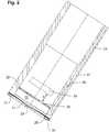
- the housing 17 is provided with a shielding device, which is arranged at a distance a in the direction of the furnace atmosphere and is designed as a flexible material layer 21 and is connected at its periphery to a housing wall 22 such that a between the material layer 21 and the protective plate 20 Intermediate space 23 is formed on all sides.
- the pliable material layer 21 is designed in the present case as a cloth, the material layer 21 being fastened to an end edge 32 of the housing 17 by means of a flange ring 31.
- the housing wall 22 has a fluid line 24, here designed as a bore extending in the longitudinal direction of the housing 17 within the housing wall 22, which opens into the intermediate space 23 with an outlet opening 25.
- the fluid line 24 enables a fluid flow 26, in the present case designed as a nitrogen flow, to be introduced from outside the shaft furnace 10 into the intermediate space 23.
- a fluid supply line is preferably provided in an area outside the shaft furnace, with a valve device that enables the setting of a defined fluid flow 26, wherein preferably both the pressure and the volume flow of the fluid flow 26 and a defined time-dependent pressure profile of the fluid flow 26 are predetermined can.
- the valve device can be used to apply pressure to the material layer 21 that changes as a function of time, that is, for example, to apply pressure pulses of a defined height every second. Depending on the pressure pulses, there is a pulsating widening of the flow cross-sections of pores 30 ( 3 and 4 ) of the material layer 21, whereby the material layer 21 is set in vibration.
- the vibrations can be superimposed with a fluttering of the material layer 21, in particular in the case of a slack, ie sagging arrangement of the material layer 21 on the housing 17. It is also possible to arrange a material layer 21, which has sufficient elasticity to form an oscillation amplitude, with a prestress on the housing 17.
- both the longitudinal threads 27 and the transverse threads 28 are provided with an elastic covering.
- the longitudinal threads 27 and the transverse threads 28 consist of glass fiber, which are coated with Teflon to form the covering.
- Fig. 3 shows the material layer 21 without pressurization.
- material layer 21 is shown with pores 30 widened as a result of pressurization.
- the pores 30 are designed to be correspondingly smaller in the event of a pressure drop, so that in the case of an elastic material layer 21 not only does the material layer 21 as such show an oscillation amplitude, but also the pores 30 of the material layer vibrate or pulsate.
- Dusty layer deposited in the material layer 21 is therefore shaken off due to the vibrations of the material layer 21.
- the material layer 21 prevents a covering layer from forming on the protective plate 20.
Landscapes
- Physics & Mathematics (AREA)
- Engineering & Computer Science (AREA)
- Remote Sensing (AREA)
- Radar, Positioning & Navigation (AREA)
- General Physics & Mathematics (AREA)
- Electromagnetism (AREA)
- Fluid Mechanics (AREA)
- Computer Networks & Wireless Communication (AREA)
- Thermal Sciences (AREA)
- Details Of Aerials (AREA)
- Radar Systems Or Details Thereof (AREA)
- Variable-Direction Aerials And Aerial Arrays (AREA)
- Shielding Devices Or Components To Electric Or Magnetic Fields (AREA)
- Aerials With Secondary Devices (AREA)
Description
- Die vorliegende Erfindung betrifft eine Radarantenneneinrichtung mit einer in einem Gehäuse aufgenommenen Antennenanordnung, die zur Abtrennung gegenüber einer in einem Ofenraum ausgebildeten Ofenatmosphäre mit einer am Gehäuse angeordneten radartransparenten Schutzplatte versehen ist. Des Weiteren betrifft die Erfindung ein Verfahren zur Abschirmung einer Radarstrahlung emittierenden Radarantenneneinrichtung umfassend eine in einem Gehäuse angeordnete Antenneneinrichtung, die zur Abtrennung gegenüber einer in einem Ofenraum ausgebildeten Ofenatmosphäre mit einer am Gehäuse angeordneten radartransparenten Schutzplatte versehen ist.
- Radarantenneneinrichtungen der eingangs genannten Art sind in einem Ofenraum angeordnet und werden zur Bestimmung der Topographie der Mölleroberfläche in einem Schachtofen verwendet. Hierzu wird die Mölleroberfläche mit einer von Antennen einer Antennenanordnung emittierten Radarstrahlung beaufschlagt. Zum Schutz der Antennenanordnung gegenüber der Ofenatmosphäre ist eine die Antennenanordnung gegenüber der Ofenatmosphäre abtrennende radartransparente Schutzplatte vorgesehen, so dass insbesondere der in der Ofenatmosphäre enthaltene Staub nicht auf die Antennenanordnung gelangt. In Verbindung mit der in der Ofenatmosphäre enthaltenen Feuchte bildet sich auf der Plattenoberfläche eine Ablagerung aus, die die zum bestimmungsgemäßen Betrieb der Radarantenneneinrichtung notwendige Radartransparenz der Schutzplatte reduziert, so dass eine regelmäßige Säuberung der Schutzplatte notwendig ist, um eine zuverlässige Bestimmung der Topographie der Mölleroberfläche durchführen zu können.
- Aus der
WO 2010/144936 A1 ist eine Radarantenneneinrichtung bekannt, bei der zur Reinigung einer der Antennenanordnung vorgeordneten Schutzplatte eine auf die Oberfläche der Schutzplatte ausgerichtete Spüldüse vorgesehen ist, mittels der kontinuierlich ein Spülfluid gegen die Plattenoberfläche gesprüht wird. Mittels der aus derWO 2010/144936 A1 bekannten Spülung der Schutzplatte lässt sich zwar immer wieder eine Reinigung der Plattenoberfläche durchführen, wobei jedoch festzustellen ist, dass es im Laufe eines längeren Betriebs der Radarantenneneinrichtung trotz kontinuierlicher Spülung der Plattenoberfläche zu einer zunehmenden Eintrübung der Schutzplatte kommt, so dass letztendlich der Austausch der Schutzplatte notwendig wird. - Der vorliegenden Erfindung liegt die Aufgabe zugrunde, eine Radarantenneneinrichtung bzw. ein Verfahren zur Abschirmung einer Radarantenneneinrichtung vorzuschlagen, das eine verlängerte Standzeit der die Antennenanordnung gegenüber der Ofenatmosphäre abtrennenden Schutzplatte ermöglicht.
- Zur Lösung dieser Aufgabe weist die erfindungsgemäße Radarantrenneneinrichtung die Merkmale des Anspruchs 1 auf.
- Erfindungsgemäß ist der Schutzplatte mit Abstand eine mit Poren versehene radartransparente biegeschlaffe Materiallage als Abschirmung vorgeordnet, derart, dass ein gegenüber dem Ofenraum durch die Materiallage abgetrennter Zwischenraum gebildet ist, in den eine Fluidleitung zur Beaufschlagung der Materiallage mit einer Fluidströmung einmündet.
- Die erfindungsgemäße Radarantenneneinrichtung verhindert aufgrund der der Schutzplatte als Abschirmung vorgeordneten Materiallage eine unmittelbare Beaufschlagung der Schutzplatte mit in der Ofenatmosphäre enthaltenem Staub. Vielmehr lagert sich der aus der Ofenatmosphäre stammende Staub an der Oberfläche der Materiallage ab. Der zwischen der Materiallage und der Schutzplatte ausgebildete Zwischenraum kann über die in den Zwischenraum einmündende Fluidleitung mit einem unter Druck stehenden Fluid, insbesondere Stickstoff, beaufschlagt werden, derart, dass der Stickstoff durch die Poren der Materiallage in den Ofenraum entweicht und dabei aufgrund des durch die Materiallage gebildeten Strömungswiderstands die Materiallage in Schwingungen versetzt. Aufgrund der von der Materiallage ausgeführten Schwingungen und der Durchströmung der in der Materiallage ausgebildeten Poren wird ein auf der Materiallage abgelagerter Staub abgeschüttelt bzw. von der Materiallage abgeblasen.
- Im Unterschied zu der bekannten Vorrichtung, bei der eine unmittelbare Beaufschlagung der Schutzplatte mit einem Spülfluid erfolgt, ermöglicht die erfindungsgemäße Radarantenneneinrichtung einerseits, dass sich aufgrund der vorgeordneten Materiallage erst gar kein Staub oder ggf. nur in einem wesentlich geringeren Ausmaß Staub auf der Schutzplatte ablagert, und andererseits, dass der stattdessen auf der Materiallage abgelagerte Staub von dieser entfernt wird. Die somit in jedem Fall zumindest stark reduzierte Staubbelastung der Schutzplatte ermöglicht insgesamt eine erhöhte Standzeit der Schutzplatte.
- Vorzugsweise ist die Materiallage elastisch ausgebildet, so dass hierdurch die Ausbildung von Schwingungen der Materiallage noch unterstützt wird. Eine elastische Ausgestaltung der Materiallage ist jedoch keine Voraussetzung für die Erzeugung von Schwingungen der Materiallage. Die Ausbildung von Schwingungen kann auch bereits dadurch gefördert werden, dass die biegeschlaffe Materiallage ohne Vorspannung, also insbesondere mit Durchhang am Gehäuse angeordnet ist, so dass ein Flattern der Materiallage infolge der Druckbeaufschlagung durch die Fluidströmung ermöglicht wird.
- Besonders vorteilhaft ist es, wenn die Materiallage eine Gewebestruktur aufweist, also etwa als Tuch ausgebildet ist, so dass über das Gewebedesign die Ausbildung einer definierten konstanten Porenweite in der Materiallage möglich ist.
- Wenn das Gewebe darüber hinaus zumindest anteilig elastische Längsfäden oder Querfäden aufweist, lässt sich auch die gewünschte Elastizität der Gewebestruktur definiert einstellen.
- Hierzu können die Längsfäden oder Querfäden mit einer elastischen Umhüllung versehen sein, insbesondere aus einem Material oder in einer Materialstärke, die die gewünschten elastischen Eigenschaften ermöglicht.
- Alternativ ist es möglich, dass die Längsfäden oder Querfäden mit einem elastischen Material imprägniert sind.
- Vorteilhaft ist es auch, wenn die Fluidleitung zumindest anteilig in einer Gehäusewandung des Gehäuses ausgebildet ist, so dass die Einleitung der Fluidströmung in den Zwischenraum ohne zusätzliche Installationen möglich ist.
- Wenn die Fluidleitung zumindest bereichsweise mit einer Heizeinrichtung versehen ist, kann eine Kondensation der in der Ofenatmosphäre enthaltenen Feuchtigkeit an der Materiallage und damit die Möglichkeit der Ausbildung einer feuchten Staubschicht an der Materiallage verhindert werden.
- Das erfindungsgemäße Verfahren weist die Merkmale des Anspruchs 9 auf.
- Erfindungsgemäß ist der Schutzplatte zur Abschirmung eine mit Poren versehene radartransparente biegeschlaffe Materiallage vorgeordnet, derart, dass von der Schutzplatte und der Materiallage ein gegenüber dem Ofenraum abgetrennter Zwischenraum ausgebildet wird, und die Materiallage wird mittels einer in den Zwischenraum einmündenden Fluidleitung zur Erzeugung von Schwingungen der Materiallage mit einer die Poren der Materiallage durchdringenden Fluidströmung beaufschlagt.
- Vorzugsweise erfolgt die Beaufschlagung der Materiallage mit einer Stickstoffströmung.
- Besonders vorzugsweise wird die Fluidströmung beheizt.
- Wenn die Strömungsbeaufschlagung zur Ausbildung eines zeitabhängigen Beaufschlagungsprofils mit wechselndem Druck erfolgt, kann eine Abstimmung zwischen dem Beaufschlagungsprofil und der Schwingungsfrequenz der Materiallage erfolgen, derart, dass besonders große Resonanzamplituden der Schwingungen der Materiallage ausgelöst werden.
- Eine besonders gute Abstimmung zwischen dem Beaufschlagungsprofil und dem Schwingungsverhalten der Materiallage zur Erzeugung von Resonanzschwingungen wird möglich, wenn eine Abstimmung der Materiallage in ihrem Aufbau und/oder ihrer Elastizität auf das Beaufschlagungsprofil erfolgt.
- Nachfolgend wird eine bevorzugte Ausführungsform der Radarantenneneinrichtung anhand der Zeichnungen näher erläutert.
- Es zeigen:
- Fig. 1
- eine in einem Ofenraum eines Schachtofens angeordnete Radareinrichtung;
- Fig. 2
- eine vergrößerte Schnittdarstellung der in
Fig. 1 gezeig-ten Radareinrichtung mit einer vor einer Schutzplatte an-geordneten Materiallage; - Fig. 3
- eine vergrößerte Teildarstellung der Materiallage gemäß Ansicht X in
Fig. 2 ohne Strömungsbeaufschlagung; - Fig. 4
- die in
Fig. 3 darstellte Materiallage mit Strömungsbeauf-schlagung. -
Fig. 1 zeigt einen Oberofen 10 eines Schachtofens mit einer mittels eines hier nicht näher dargestellten Deckels verschließbaren Ofenöffnung 13, durch die die Beschickung des Schachtofens mit inFig. 1 im Einzelnen nicht näher dargestellten Koks- und Möllerschichten erfolgt. In einem Ofenunterteil 12 ist eine Mölleroberfläche 14 ausgebildet, oberhalb der eine zur Ofenöffnung 13 hin aufsteigende heiße Gase enthaltende Atmosphäre ausgebildet ist. Die Atmosphäre ist aufgrund der Beschickung des Ofens stark mit Staub belastet. - Zur Erfassung der in
Fig. 1 dargestellten Mölleroberfläche 14 ist in einer Ofenwandung 15 des Oberofens 10 eine Radarantenneneinrichtung 16 angeordnet, die in einem Gehäuse 17, das in einer die Ofenwandung 15 durchdringenden Gehäuseaufnahme 18 angeordnet ist, eine Antennenanordnung 19 aufweist. Die Antennenanordnung 19 ist zur Ofenatmosphäre hin mit einer radartransparenten Schutzplatte 20 abgedeckt, die im vorliegenden Fall eine frontseitige Gehäusewandung ausbildet. Wie inFig. 2 dargestellt, ist das Gehäuse 17 mit einer in einem Abstand a in Richtung auf die Ofenatmosphäre angeordneten, als biegeschlaffe Materiallage 21 ausgeführten Abschirmeinrichtung versehen, die an ihrer Peripherie mit einer Gehäusewandung 22 verbunden ist, derart, dass zwischen der Materiallage 21 und der Schutzplatte 20 ein allseitig begrenzter Zwischenraum 23 ausgebildet ist. - Die biegeschlaffe Materiallage 21 ist im vorliegenden Fall als Tuch ausgebildet, wobei das Materiallage 21 mittels eines Flanschrings 31 an einem stirnseitigen Rand 32 des Gehäuses 17 befestigt ist.
- Wie
Fig. 2 weiter zeigt, weist die Gehäusewandung 22 eine hier als sich in Längsrichtung des Gehäuses 17 innerhalb der Gehäusewand 22 erstreckende Bohrung ausgeführte Fluidleitung 24 auf, die mit einer Austrittsöffnung 25 in den Zwischenraum 23 einmündet. Die Fluidleitung 24 ermöglicht eine Einleitung einer im vorliegenden Fall als Stickstoffströmung ausgebildete Fluidströmung 26 von außerhalb des Schachtofens 10 in den Zwischenraum 23. - Vorzugsweise in einem Bereich außerhalb des Schachtofens ist eine hier nicht näher dargestellte Fluidzuleitung vorgesehen mit einer Ventileinrichtung, die die Einstellung einer definierten Fluidströmung 26 ermöglicht, wobei vorzugsweise sowohl der Druck und der Volumenstrom der Fluidströmung 26 als auch ein definierter zeitabhängiger Druckverlauf der Fluidströmung 26 vorgegeben werden können. Mittels der Ventileinrichtung kann eine sich in Abhängigkeit von der Zeit ändernde Druckbeaufschlagung der Materiallage 21, also beispielsweise die Beaufschlagung mit Druckimpulsen definierter Höhe im Sekundentakt, erfolgen. In Abhängigkeit von den Druckimpulsen erfolgt eine pulsierende Aufweitung der Durchströmungsquerschnitte von Poren 30 (
Fig. 3 und 4 ) der Materiallage 21, wodurch die Materiallage 21 in Schwingung versetzt wird. Die Schwingungen können insbesondere bei einer schlaffen, also einen Durchhang aufweisende Anordnung der Materiallage 21 am Gehäuse 17 mit einem Flattern der Materiallage 21 überlagert werden. Auch ist es möglich, eine Materiallage 21, die eine zur Ausbildung einer Schwingungsamplitude ausreichende Elastizität aufweist, mit Vorspannung am Gehäuse 17 anzuordnen. - In den
Fig. 3 und 4 ist eine vergrößerte Aufsicht auf die Materiallage 21 dargestellt, wobei die Materiallage 21 im vorliegenden Fall eine Gewebestruktur 33 aufweist mit einander kreuzenden Längsfäden 27 und Querfäden 28, die die Poren 30 begrenzen und somit den Durchströmungsquerschnitt der Poren 30 definieren. Im vorliegenden Fall sind sowohl die Längsfäden 27 als auch die Querfäden 28 mit einer elastischen Umhüllung versehen. Beispielsweise können die Längsfäden 27 und die Querfäden 28 aus Glasfaser bestehen, die zur Ausbildung der Umhüllung mit Teflon ummantelt sind. -
Fig. 3 zeigt die Materiallage 21 ohne Druckbeaufschlagung. InFig. 4 ist die Materiallage 21 mit infolge einer Druckbeaufschlagung geweiteten Poren 30 dargestellt. Im Vergleich hierzu sind die Poren 30 bei einem Druckabfall entsprechend kleiner ausgebildet, so dass bei einer elastisch ausgebildeten Materiallage 21 nicht nur die Materiallage 21 als solche eine Schwingungsamplitude zeigt, sondern darüber hinaus auch ein Schwingen oder Pulsieren der Poren 30 der Materiallage erfolgt. - Eine auf der der Ofenatmosphäre zugewandten Frontseite 29 (
Fig. 2 ) der Materiallage 21 abgelagerte staubhaltige Schicht wird demnach aufgrund der Schwingungen der Materiallage 21 abgeschüttelt. Gleichzeitig verhindert die Materiallage 21, dass sich auf der Schutzplatte 20 eine Belagsschicht ausbildet.
Claims (13)
- Radarantenneneinrichtung (16) mit einer in einem Gehäuse (17) aufgenommenen Antennenanordnung (19), die zur Abtrennung gegenüber einer in einem Ofenraum ausgebildeten Ofenatmosphäre mit einer am Gehäuse angeordneten radartransparenten Schutzplatte (20) versehen ist,
dadurch gekennzeichnet,
dass der Schutzplatte (20) mit Abstand eine mit Poren (30) versehene radartransparente biegeschlaffe Materiallage (21) als Abschirmung vorgeordnet ist, derart, dass ein gegenüber dem Ofenraum durch die Materiallage (21) abgetrennter Zwischenraum (23) gebildet ist, in den eine Fluidleitung (24) zur Beaufschlagung der Materiallage (21) mit einer Fluidströmung (26) einmündet. - Radarantenneneinrichtung nach Anspruch 1,
dadurch gekennzeichnet,
dass die Materiallage (21) elastisch ausgebildet ist. - Radarantenneneinrichtung nach Anspruch 1 oder 2,
dadurch gekennzeichnet,
dass die Materiallage (21) eine Gewebestruktur (33) aufweist. - Radarantenneneinrichtung nach Anspruch 3,
dadurch gekennzeichnet,
dass die Gewebestruktur (33) zumindest anteilig elastische Längsfäden (27) oder Querfäden(28) aufweist. - Radarantenneneinrichtung nach Anspruch 4,
dadurch gekennzeichnet,
dass die Längsfäden (27) oder Querfäden (28) eine elastische Umhüllung (29) aufweisen. - Radarantenneneinrichtung nach Anspruch 4,
dadurch gekennzeichnet,
dass die Längsfäden (27) oder Querfäden (28) mit einem elastischen Material imprägniert sind. - Radarantenneneinrichtung nach einem der vorangehenden Ansprüche,
dadurch gekennzeichnet,
dass die Fluidleitung (24) zumindest anteilig in einer Gehäusewandung (22) des Gehäuses (17) ausgebildet ist. - Radarantenneneinrichtung nach einem der vorangehenden Ansprüche,
dadurch gekennzeichnet,
dass die Fluidleitung (24) zumindest bereichsweise mit einer Heizeinrichtung versehen ist. - Verfahren zur Abschirmung einer Radarstrahlung emittierenden Radarantenneneinrichtung (16) umfassend eine in einem Gehäuse (17) angeordnete Antennenanordnung (19), die zur Abtrennung gegenüber einer in einem Ofenraum ausgebildeten Ofenatmosphäre mit einer am Gehäuse (17) angeordneten radartransparenten Schutzplatte (20) versehen ist,
dadurch gekennzeichnet,
dass der Schutzplatte (20) zur Abschirmung gegenüber der Ofenatmosphäre einer mit Poren (30) versehene radartransparente biegeschlaffe Materiallage (21) vorgeordnet ist, derart, dass zwischen der Schutzplatte (20) und der Materiallage (21) ein gegenüber dem Ofenraum abgetrennter Zwischenraum (23) gebildet wird, und die Materiallage (21) mittels einer in den Zwischenraum (23) einmündenden Fluidleitung (24) zur Erzeugung von Schwingungen der Materiallage (21) mit einer die Poren (30) der Materiallage durchdringenden Fluidströmung (26) beaufschlagt wird. - Verfahren nach Anspruch 9,
dadurch gekennzeichnet,
dass die Fluidströmung (26) beheizt wird. - Verfahren nach Anspruch 9 oder 10,
dadurch gekennzeichnet,
dass die Fluidströmung (26) als Stickstoffströmung ausgebildet ist. - Verfahren nach einem der Ansprüche 9 bis 11,
dadurch gekennzeichnet,
dass die Strömungsbeaufschlagung zur Ausbildung eines zeitabhängigen Beaufschlagungsprofils mit wechselndem Druck erfolgt. - Verfahren nach einem der Ansprüche 9 bis 12,
dadurch gekennzeichnet,
dass zur Erzeugung von Schwingungen der Materiallage eine Abstimmung der Materiallage (21) in ihrem Aufbau und/oder ihrer Elastizität auf das Beaufschlagungsprofil erfolgt.
Priority Applications (1)
| Application Number | Priority Date | Filing Date | Title |
|---|---|---|---|
| PL16718612T PL3440735T3 (pl) | 2016-04-07 | 2016-04-07 | Mechanizm anteny radarowej oraz sposób ekranowania mechanizmu anteny radarowej |
Applications Claiming Priority (1)
| Application Number | Priority Date | Filing Date | Title |
|---|---|---|---|
| PCT/EP2016/057579 WO2017174135A1 (de) | 2016-04-07 | 2016-04-07 | Radarantenneneinrichtung sowie verfahren zur abschirmung einer radarantenneneinrichtung |
Publications (2)
| Publication Number | Publication Date |
|---|---|
| EP3440735A1 EP3440735A1 (de) | 2019-02-13 |
| EP3440735B1 true EP3440735B1 (de) | 2020-02-12 |
Family
ID=55809073
Family Applications (1)
| Application Number | Title | Priority Date | Filing Date |
|---|---|---|---|
| EP16718612.1A Active EP3440735B1 (de) | 2016-04-07 | 2016-04-07 | Radarantenneneinrichtung sowie verfahren zur abschirmung einer radarantenneneinrichtung |
Country Status (10)
| Country | Link |
|---|---|
| US (1) | US11114754B2 (de) |
| EP (1) | EP3440735B1 (de) |
| JP (1) | JP6903076B2 (de) |
| KR (1) | KR102039849B1 (de) |
| CN (1) | CN109314304A (de) |
| BR (1) | BR112018070457A2 (de) |
| PL (1) | PL3440735T3 (de) |
| RU (1) | RU2696341C1 (de) |
| UA (1) | UA122090C2 (de) |
| WO (1) | WO2017174135A1 (de) |
Families Citing this family (3)
| Publication number | Priority date | Publication date | Assignee | Title |
|---|---|---|---|---|
| EP3605032B1 (de) * | 2018-08-02 | 2021-06-02 | VEGA Grieshaber KG | Radarsensor zur füllstand- oder grenzstandmessung |
| CN109031267B (zh) * | 2018-10-09 | 2020-06-23 | 中国人民解放军国防科技大学 | 一种空间分离平板的三维电磁散射参数化模型构建方法 |
| DE102020133545A1 (de) * | 2020-12-15 | 2022-06-15 | TMT - Tapping Measuring Technology GmbH | Vorrichtung und Verfahren zur Entnahme von Gasproben aus einem Hochofen |
Family Cites Families (20)
| Publication number | Priority date | Publication date | Assignee | Title |
|---|---|---|---|---|
| LU74579A1 (de) * | 1976-03-17 | 1976-09-01 | ||
| BE872578A (fr) | 1978-12-06 | 1979-03-30 | Centre Rech Metallurgique | Dispositif pour controler la surface de la charge d'un four a cuve |
| JPS59207701A (ja) | 1983-05-11 | 1984-11-24 | Hokuriku Electric Power Co Inc:The | パラボラ型アンテナの着雪防止装置 |
| LU87578A1 (fr) * | 1989-09-07 | 1991-05-07 | Wurth Paul Sa | Dispositif de determination de la carte topographique de la surface de chargement d'un four a cuve |
| DE10333618B3 (de) | 2003-07-24 | 2005-03-24 | Saint-Gobain Sekurit Deutschland Gmbh & Co. Kg | Substrat mit einer elektrisch leitfähigen Beschichtung und einem Kommunikationsfenster |
| US9306290B1 (en) * | 2007-05-31 | 2016-04-05 | Foersvarets Materielverk | Controller barrier layer against electromagnetic radiation |
| JP5104454B2 (ja) | 2008-03-25 | 2012-12-19 | 日東紡績株式会社 | バグフィルタ用ガラス繊維織物 |
| CN101492750B (zh) * | 2008-12-30 | 2010-12-29 | 北京科技大学 | 基于工业相控阵雷达的高炉料面测量与控制系统 |
| AT508369B1 (de) | 2009-06-17 | 2011-01-15 | Vatron Gmbh | Verfahren und vorrichtung zur berechnung einer oberfläche eines füllguts eines behälters |
| JP5313794B2 (ja) | 2009-07-13 | 2013-10-09 | 新日鉄住金エンジニアリング株式会社 | 層高レベル検知装置及び工業炉 |
| TWI412598B (zh) | 2010-02-05 | 2013-10-21 | China Steel Corp | Design method of standing blast furnace material |
| KR101778329B1 (ko) * | 2010-04-26 | 2017-09-26 | 해치 리미티드 | 야금로 내의 차지 뱅크 레벨 측정 |
| JP5787607B2 (ja) * | 2011-05-10 | 2015-09-30 | 新日鐵住金株式会社 | 高炉内装入物のプロフィル測定装置 |
| JP5178939B1 (ja) * | 2012-07-11 | 2013-04-10 | 和宏 永田 | マイクロ波によるシリコンの製造方法及びマイクロ波還元炉 |
| DE102012016120B4 (de) | 2012-08-15 | 2017-12-07 | Krohne Messtechnik Gmbh | Mikrowellenfenster und nach dem Radar-Prinzip arbeitendes Füllstandmesssystem |
| JP2014215166A (ja) | 2013-04-25 | 2014-11-17 | 株式会社ワイヤーデバイス | 距離測定装置 |
| DE102014200928B4 (de) | 2014-01-20 | 2025-06-26 | Tmt Tapping Measuring Technology Sàrl | Vorrichtung zur Bestimmung der Topographie der Mölleroberfläche in einem Schachtofen |
| JP6495675B2 (ja) | 2014-02-18 | 2019-04-03 | 株式会社Wadeco | コークス炉の装炭レベル測定装置 |
| JP2015219129A (ja) * | 2014-05-19 | 2015-12-07 | 株式会社ワイヤーデバイス | 高炉内装入物の表面検出装置 |
| US10454161B1 (en) * | 2016-03-04 | 2019-10-22 | Raytheon Company | Radome assembly |
-
2016
- 2016-04-07 BR BR112018070457A patent/BR112018070457A2/pt active Search and Examination
- 2016-04-07 PL PL16718612T patent/PL3440735T3/pl unknown
- 2016-04-07 UA UAA201810661A patent/UA122090C2/uk unknown
- 2016-04-07 KR KR1020187030882A patent/KR102039849B1/ko not_active Expired - Fee Related
- 2016-04-07 RU RU2018136301A patent/RU2696341C1/ru active
- 2016-04-07 WO PCT/EP2016/057579 patent/WO2017174135A1/de not_active Ceased
- 2016-04-07 CN CN201680086540.3A patent/CN109314304A/zh active Pending
- 2016-04-07 EP EP16718612.1A patent/EP3440735B1/de active Active
- 2016-04-07 US US16/090,864 patent/US11114754B2/en not_active Expired - Fee Related
- 2016-04-07 JP JP2018552248A patent/JP6903076B2/ja not_active Expired - Fee Related
Non-Patent Citations (1)
| Title |
|---|
| None * |
Also Published As
| Publication number | Publication date |
|---|---|
| PL3440735T3 (pl) | 2020-07-27 |
| BR112018070457A2 (pt) | 2019-02-05 |
| KR102039849B1 (ko) | 2019-11-01 |
| US20200328508A1 (en) | 2020-10-15 |
| JP6903076B2 (ja) | 2021-07-14 |
| EP3440735A1 (de) | 2019-02-13 |
| US11114754B2 (en) | 2021-09-07 |
| RU2696341C1 (ru) | 2019-08-01 |
| CN109314304A (zh) | 2019-02-05 |
| JP2019516957A (ja) | 2019-06-20 |
| KR20190002483A (ko) | 2019-01-08 |
| WO2017174135A1 (de) | 2017-10-12 |
| UA122090C2 (uk) | 2020-09-10 |
Similar Documents
| Publication | Publication Date | Title |
|---|---|---|
| EP3302812B1 (de) | Fluidischer oszillator | |
| EP2427309B1 (de) | Verfahren und vorrichtung zur herstellung eines fadens aus einer mehrzahl von einzelfilamenten | |
| DE3727843C2 (de) | Vorrichtung zum Erzeugen von Flüssigkeitsstrahlen | |
| EP1997547B1 (de) | Verfahren zum Rückspülen von Filtern | |
| EP0124841A2 (de) | Verfahren zum Waschen der Filterelemente eines Gasfilters und Vorrichtung zum Durchführen des Verfahrens | |
| EP2180931A2 (de) | Gewelltes oder gefaltetes flachmaterial | |
| DE2857321C2 (de) | Verfahren zum Aufsprühen eines monolithischen hitzebeständigen Materials | |
| DE2830388A1 (de) | Zentrifugensieb, insbesondere fuer eine schubzentrifuge | |
| EP3440735A1 (de) | Radarantenneneinrichtung sowie verfahren zur abschirmung einer radarantenneneinrichtung | |
| DE102014011678A1 (de) | Filterkerzenelement mit Metallschaumverstärkung | |
| WO2013010535A2 (de) | Filter, insbesondere atemluftfilter | |
| DE19848394C1 (de) | Filteranordnung, insbesondere für den Einsatz als Fettfilter in Dunstabzügen bei Kochstellen | |
| EP3521215A1 (de) | Schwingförderer | |
| DE10250298A9 (de) | Tür mit Sichtfenster für Mikrowellengeräte | |
| DE102005055955B3 (de) | Solarempfänger | |
| DE29508608U1 (de) | Vorrichtung zum Reinigen staubhaltiger Luft | |
| DE2301276A1 (de) | Filtereinrichtung fuer beatmungsgeraete und dergl | |
| EP4506055B1 (de) | Filter für ein sprühbeschichtungssystem und filteranordnung | |
| DE102013202216A1 (de) | Herstellverfahren einer Hausgerätevorrichtung und Hausgerätevorrichtung | |
| DE2327089C3 (de) | Pneumatische Schleuderpistole für die Herstellung von nicht-gewebten Bahnen aus Filamenten | |
| EP0953526B1 (de) | Vorrichtung zum Fördern von Schüttgütern | |
| DE19635156C2 (de) | Verfahren zur Herstellung von Sieben | |
| DE202018100139U1 (de) | Schalldämpfelement für eine raumlufttechnische Klima- und/oder Lüftungsanlage | |
| DE2409740C3 (de) | ||
| DE102016217994A1 (de) | Luftfederbalg |
Legal Events
| Date | Code | Title | Description |
|---|---|---|---|
| STAA | Information on the status of an ep patent application or granted ep patent |
Free format text: STATUS: THE INTERNATIONAL PUBLICATION HAS BEEN MADE |
|
| PUAI | Public reference made under article 153(3) epc to a published international application that has entered the european phase |
Free format text: ORIGINAL CODE: 0009012 |
|
| STAA | Information on the status of an ep patent application or granted ep patent |
Free format text: STATUS: REQUEST FOR EXAMINATION WAS MADE |
|
| 17P | Request for examination filed |
Effective date: 20181102 |
|
| AK | Designated contracting states |
Kind code of ref document: A1 Designated state(s): AL AT BE BG CH CY CZ DE DK EE ES FI FR GB GR HR HU IE IS IT LI LT LU LV MC MK MT NL NO PL PT RO RS SE SI SK SM TR |
|
| AX | Request for extension of the european patent |
Extension state: BA ME |
|
| DAV | Request for validation of the european patent (deleted) | ||
| DAX | Request for extension of the european patent (deleted) | ||
| GRAP | Despatch of communication of intention to grant a patent |
Free format text: ORIGINAL CODE: EPIDOSNIGR1 |
|
| STAA | Information on the status of an ep patent application or granted ep patent |
Free format text: STATUS: GRANT OF PATENT IS INTENDED |
|
| INTG | Intention to grant announced |
Effective date: 20190903 |
|
| GRAS | Grant fee paid |
Free format text: ORIGINAL CODE: EPIDOSNIGR3 |
|
| GRAA | (expected) grant |
Free format text: ORIGINAL CODE: 0009210 |
|
| STAA | Information on the status of an ep patent application or granted ep patent |
Free format text: STATUS: THE PATENT HAS BEEN GRANTED |
|
| AK | Designated contracting states |
Kind code of ref document: B1 Designated state(s): AL AT BE BG CH CY CZ DE DK EE ES FI FR GB GR HR HU IE IS IT LI LT LU LV MC MK MT NL NO PL PT RO RS SE SI SK SM TR |
|
| REG | Reference to a national code |
Ref country code: GB Ref legal event code: FG4D Free format text: NOT ENGLISH |
|
| REG | Reference to a national code |
Ref country code: CH Ref legal event code: EP |
|
| REG | Reference to a national code |
Ref country code: AT Ref legal event code: REF Ref document number: 1233316 Country of ref document: AT Kind code of ref document: T Effective date: 20200215 |
|
| REG | Reference to a national code |
Ref country code: IE Ref legal event code: FG4D Free format text: LANGUAGE OF EP DOCUMENT: GERMAN |
|
| REG | Reference to a national code |
Ref country code: DE Ref legal event code: R096 Ref document number: 502016008709 Country of ref document: DE |
|
| REG | Reference to a national code |
Ref country code: NL Ref legal event code: FP |
|
| PG25 | Lapsed in a contracting state [announced via postgrant information from national office to epo] |
Ref country code: RS Free format text: LAPSE BECAUSE OF FAILURE TO SUBMIT A TRANSLATION OF THE DESCRIPTION OR TO PAY THE FEE WITHIN THE PRESCRIBED TIME-LIMIT Effective date: 20200212 Ref country code: NO Free format text: LAPSE BECAUSE OF FAILURE TO SUBMIT A TRANSLATION OF THE DESCRIPTION OR TO PAY THE FEE WITHIN THE PRESCRIBED TIME-LIMIT Effective date: 20200512 Ref country code: FI Free format text: LAPSE BECAUSE OF FAILURE TO SUBMIT A TRANSLATION OF THE DESCRIPTION OR TO PAY THE FEE WITHIN THE PRESCRIBED TIME-LIMIT Effective date: 20200212 |
|
| REG | Reference to a national code |
Ref country code: LT Ref legal event code: MG4D |
|
| PG25 | Lapsed in a contracting state [announced via postgrant information from national office to epo] |
Ref country code: SE Free format text: LAPSE BECAUSE OF FAILURE TO SUBMIT A TRANSLATION OF THE DESCRIPTION OR TO PAY THE FEE WITHIN THE PRESCRIBED TIME-LIMIT Effective date: 20200212 Ref country code: LV Free format text: LAPSE BECAUSE OF FAILURE TO SUBMIT A TRANSLATION OF THE DESCRIPTION OR TO PAY THE FEE WITHIN THE PRESCRIBED TIME-LIMIT Effective date: 20200212 Ref country code: IS Free format text: LAPSE BECAUSE OF FAILURE TO SUBMIT A TRANSLATION OF THE DESCRIPTION OR TO PAY THE FEE WITHIN THE PRESCRIBED TIME-LIMIT Effective date: 20200612 Ref country code: BG Free format text: LAPSE BECAUSE OF FAILURE TO SUBMIT A TRANSLATION OF THE DESCRIPTION OR TO PAY THE FEE WITHIN THE PRESCRIBED TIME-LIMIT Effective date: 20200512 Ref country code: HR Free format text: LAPSE BECAUSE OF FAILURE TO SUBMIT A TRANSLATION OF THE DESCRIPTION OR TO PAY THE FEE WITHIN THE PRESCRIBED TIME-LIMIT Effective date: 20200212 Ref country code: GR Free format text: LAPSE BECAUSE OF FAILURE TO SUBMIT A TRANSLATION OF THE DESCRIPTION OR TO PAY THE FEE WITHIN THE PRESCRIBED TIME-LIMIT Effective date: 20200513 |
|
| PG25 | Lapsed in a contracting state [announced via postgrant information from national office to epo] |
Ref country code: SK Free format text: LAPSE BECAUSE OF FAILURE TO SUBMIT A TRANSLATION OF THE DESCRIPTION OR TO PAY THE FEE WITHIN THE PRESCRIBED TIME-LIMIT Effective date: 20200212 Ref country code: RO Free format text: LAPSE BECAUSE OF FAILURE TO SUBMIT A TRANSLATION OF THE DESCRIPTION OR TO PAY THE FEE WITHIN THE PRESCRIBED TIME-LIMIT Effective date: 20200212 Ref country code: EE Free format text: LAPSE BECAUSE OF FAILURE TO SUBMIT A TRANSLATION OF THE DESCRIPTION OR TO PAY THE FEE WITHIN THE PRESCRIBED TIME-LIMIT Effective date: 20200212 Ref country code: SM Free format text: LAPSE BECAUSE OF FAILURE TO SUBMIT A TRANSLATION OF THE DESCRIPTION OR TO PAY THE FEE WITHIN THE PRESCRIBED TIME-LIMIT Effective date: 20200212 Ref country code: DK Free format text: LAPSE BECAUSE OF FAILURE TO SUBMIT A TRANSLATION OF THE DESCRIPTION OR TO PAY THE FEE WITHIN THE PRESCRIBED TIME-LIMIT Effective date: 20200212 Ref country code: LT Free format text: LAPSE BECAUSE OF FAILURE TO SUBMIT A TRANSLATION OF THE DESCRIPTION OR TO PAY THE FEE WITHIN THE PRESCRIBED TIME-LIMIT Effective date: 20200212 Ref country code: ES Free format text: LAPSE BECAUSE OF FAILURE TO SUBMIT A TRANSLATION OF THE DESCRIPTION OR TO PAY THE FEE WITHIN THE PRESCRIBED TIME-LIMIT Effective date: 20200212 Ref country code: PT Free format text: LAPSE BECAUSE OF FAILURE TO SUBMIT A TRANSLATION OF THE DESCRIPTION OR TO PAY THE FEE WITHIN THE PRESCRIBED TIME-LIMIT Effective date: 20200705 |
|
| REG | Reference to a national code |
Ref country code: DE Ref legal event code: R097 Ref document number: 502016008709 Country of ref document: DE |
|
| PG25 | Lapsed in a contracting state [announced via postgrant information from national office to epo] |
Ref country code: MC Free format text: LAPSE BECAUSE OF FAILURE TO SUBMIT A TRANSLATION OF THE DESCRIPTION OR TO PAY THE FEE WITHIN THE PRESCRIBED TIME-LIMIT Effective date: 20200212 |
|
| REG | Reference to a national code |
Ref country code: CH Ref legal event code: PL |
|
| PLBE | No opposition filed within time limit |
Free format text: ORIGINAL CODE: 0009261 |
|
| STAA | Information on the status of an ep patent application or granted ep patent |
Free format text: STATUS: NO OPPOSITION FILED WITHIN TIME LIMIT |
|
| 26N | No opposition filed |
Effective date: 20201113 |
|
| PG25 | Lapsed in a contracting state [announced via postgrant information from national office to epo] |
Ref country code: LU Free format text: LAPSE BECAUSE OF NON-PAYMENT OF DUE FEES Effective date: 20200407 Ref country code: IT Free format text: LAPSE BECAUSE OF FAILURE TO SUBMIT A TRANSLATION OF THE DESCRIPTION OR TO PAY THE FEE WITHIN THE PRESCRIBED TIME-LIMIT Effective date: 20200212 Ref country code: CH Free format text: LAPSE BECAUSE OF NON-PAYMENT OF DUE FEES Effective date: 20200430 Ref country code: LI Free format text: LAPSE BECAUSE OF NON-PAYMENT OF DUE FEES Effective date: 20200430 |
|
| REG | Reference to a national code |
Ref country code: BE Ref legal event code: MM Effective date: 20200430 |
|
| PG25 | Lapsed in a contracting state [announced via postgrant information from national office to epo] |
Ref country code: SI Free format text: LAPSE BECAUSE OF FAILURE TO SUBMIT A TRANSLATION OF THE DESCRIPTION OR TO PAY THE FEE WITHIN THE PRESCRIBED TIME-LIMIT Effective date: 20200212 Ref country code: BE Free format text: LAPSE BECAUSE OF NON-PAYMENT OF DUE FEES Effective date: 20200430 |
|
| PG25 | Lapsed in a contracting state [announced via postgrant information from national office to epo] |
Ref country code: IE Free format text: LAPSE BECAUSE OF NON-PAYMENT OF DUE FEES Effective date: 20200407 |
|
| PGFP | Annual fee paid to national office [announced via postgrant information from national office to epo] |
Ref country code: CZ Payment date: 20210325 Year of fee payment: 6 |
|
| PGFP | Annual fee paid to national office [announced via postgrant information from national office to epo] |
Ref country code: PL Payment date: 20210316 Year of fee payment: 6 |
|
| PGFP | Annual fee paid to national office [announced via postgrant information from national office to epo] |
Ref country code: DE Payment date: 20210624 Year of fee payment: 6 Ref country code: FR Payment date: 20210421 Year of fee payment: 6 |
|
| PGFP | Annual fee paid to national office [announced via postgrant information from national office to epo] |
Ref country code: GB Payment date: 20210422 Year of fee payment: 6 Ref country code: AT Payment date: 20210420 Year of fee payment: 6 |
|
| PGFP | Annual fee paid to national office [announced via postgrant information from national office to epo] |
Ref country code: NL Payment date: 20210421 Year of fee payment: 6 |
|
| PG25 | Lapsed in a contracting state [announced via postgrant information from national office to epo] |
Ref country code: TR Free format text: LAPSE BECAUSE OF FAILURE TO SUBMIT A TRANSLATION OF THE DESCRIPTION OR TO PAY THE FEE WITHIN THE PRESCRIBED TIME-LIMIT Effective date: 20200212 Ref country code: MT Free format text: LAPSE BECAUSE OF FAILURE TO SUBMIT A TRANSLATION OF THE DESCRIPTION OR TO PAY THE FEE WITHIN THE PRESCRIBED TIME-LIMIT Effective date: 20200212 Ref country code: CY Free format text: LAPSE BECAUSE OF FAILURE TO SUBMIT A TRANSLATION OF THE DESCRIPTION OR TO PAY THE FEE WITHIN THE PRESCRIBED TIME-LIMIT Effective date: 20200212 |
|
| PG25 | Lapsed in a contracting state [announced via postgrant information from national office to epo] |
Ref country code: MK Free format text: LAPSE BECAUSE OF FAILURE TO SUBMIT A TRANSLATION OF THE DESCRIPTION OR TO PAY THE FEE WITHIN THE PRESCRIBED TIME-LIMIT Effective date: 20200212 Ref country code: AL Free format text: LAPSE BECAUSE OF FAILURE TO SUBMIT A TRANSLATION OF THE DESCRIPTION OR TO PAY THE FEE WITHIN THE PRESCRIBED TIME-LIMIT Effective date: 20200212 |
|
| PG25 | Lapsed in a contracting state [announced via postgrant information from national office to epo] |
Ref country code: CZ Free format text: LAPSE BECAUSE OF NON-PAYMENT OF DUE FEES Effective date: 20220407 |
|
| REG | Reference to a national code |
Ref country code: DE Ref legal event code: R119 Ref document number: 502016008709 Country of ref document: DE |
|
| REG | Reference to a national code |
Ref country code: NL Ref legal event code: MM Effective date: 20220501 |
|
| REG | Reference to a national code |
Ref country code: AT Ref legal event code: MM01 Ref document number: 1233316 Country of ref document: AT Kind code of ref document: T Effective date: 20220407 |
|
| GBPC | Gb: european patent ceased through non-payment of renewal fee |
Effective date: 20220407 |
|
| PG25 | Lapsed in a contracting state [announced via postgrant information from national office to epo] |
Ref country code: NL Free format text: LAPSE BECAUSE OF NON-PAYMENT OF DUE FEES Effective date: 20220501 Ref country code: GB Free format text: LAPSE BECAUSE OF NON-PAYMENT OF DUE FEES Effective date: 20220407 Ref country code: FR Free format text: LAPSE BECAUSE OF NON-PAYMENT OF DUE FEES Effective date: 20220430 Ref country code: DE Free format text: LAPSE BECAUSE OF NON-PAYMENT OF DUE FEES Effective date: 20221103 Ref country code: AT Free format text: LAPSE BECAUSE OF NON-PAYMENT OF DUE FEES Effective date: 20220407 |
|
| PG25 | Lapsed in a contracting state [announced via postgrant information from national office to epo] |
Ref country code: PL Free format text: LAPSE BECAUSE OF NON-PAYMENT OF DUE FEES Effective date: 20220407 |