EP3440161B1 - A waste-to-energy conversion system and method - Google Patents
A waste-to-energy conversion system and method Download PDFInfo
- Publication number
- EP3440161B1 EP3440161B1 EP17715474.7A EP17715474A EP3440161B1 EP 3440161 B1 EP3440161 B1 EP 3440161B1 EP 17715474 A EP17715474 A EP 17715474A EP 3440161 B1 EP3440161 B1 EP 3440161B1
- Authority
- EP
- European Patent Office
- Prior art keywords
- syngas
- gas
- drum
- char
- retort
- Prior art date
- Legal status (The legal status is an assumption and is not a legal conclusion. Google has not performed a legal analysis and makes no representation as to the accuracy of the status listed.)
- Active
Links
- 238000006243 chemical reaction Methods 0.000 title claims description 35
- 238000000034 method Methods 0.000 title claims description 18
- 238000005336 cracking Methods 0.000 claims description 48
- 238000000197 pyrolysis Methods 0.000 claims description 39
- 238000010791 quenching Methods 0.000 claims description 24
- 238000002156 mixing Methods 0.000 claims description 18
- 238000001816 cooling Methods 0.000 claims description 15
- 238000004140 cleaning Methods 0.000 claims description 14
- 238000010438 heat treatment Methods 0.000 claims description 13
- 150000002430 hydrocarbons Chemical class 0.000 claims description 13
- 238000012545 processing Methods 0.000 claims description 12
- 239000007787 solid Substances 0.000 claims description 12
- 229930195733 hydrocarbon Natural products 0.000 claims description 11
- 239000007921 spray Substances 0.000 claims description 10
- 230000008602 contraction Effects 0.000 claims description 6
- 238000000605 extraction Methods 0.000 claims description 6
- 239000004215 Carbon black (E152) Substances 0.000 claims description 5
- 230000005484 gravity Effects 0.000 claims description 5
- 230000004888 barrier function Effects 0.000 claims description 4
- 239000007788 liquid Substances 0.000 claims description 4
- 230000020169 heat generation Effects 0.000 claims description 3
- 239000007800 oxidant agent Substances 0.000 claims description 3
- 230000001590 oxidative effect Effects 0.000 claims description 3
- 230000033001 locomotion Effects 0.000 claims description 2
- 238000011144 upstream manufacturing Methods 0.000 claims description 2
- 239000007789 gas Substances 0.000 description 101
- 239000000463 material Substances 0.000 description 18
- 239000000446 fuel Substances 0.000 description 17
- XLYOFNOQVPJJNP-UHFFFAOYSA-N water Substances O XLYOFNOQVPJJNP-UHFFFAOYSA-N 0.000 description 15
- VNWKTOKETHGBQD-UHFFFAOYSA-N methane Chemical group C VNWKTOKETHGBQD-UHFFFAOYSA-N 0.000 description 11
- 238000011084 recovery Methods 0.000 description 11
- 238000002485 combustion reaction Methods 0.000 description 9
- 238000013461 design Methods 0.000 description 9
- 230000008569 process Effects 0.000 description 9
- 239000000919 ceramic Substances 0.000 description 7
- 239000000284 extract Substances 0.000 description 7
- 230000007246 mechanism Effects 0.000 description 7
- 239000010935 stainless steel Substances 0.000 description 6
- 229910001220 stainless steel Inorganic materials 0.000 description 6
- 239000011269 tar Substances 0.000 description 6
- QVGXLLKOCUKJST-UHFFFAOYSA-N atomic oxygen Chemical compound [O] QVGXLLKOCUKJST-UHFFFAOYSA-N 0.000 description 5
- 239000003921 oil Substances 0.000 description 5
- 239000001301 oxygen Substances 0.000 description 5
- 229910052760 oxygen Inorganic materials 0.000 description 5
- IJGRMHOSHXDMSA-UHFFFAOYSA-N Atomic nitrogen Chemical compound N#N IJGRMHOSHXDMSA-UHFFFAOYSA-N 0.000 description 4
- OKTJSMMVPCPJKN-UHFFFAOYSA-N Carbon Chemical compound [C] OKTJSMMVPCPJKN-UHFFFAOYSA-N 0.000 description 4
- CURLTUGMZLYLDI-UHFFFAOYSA-N Carbon dioxide Chemical compound O=C=O CURLTUGMZLYLDI-UHFFFAOYSA-N 0.000 description 4
- UGFAIRIUMAVXCW-UHFFFAOYSA-N Carbon monoxide Chemical compound [O+]#[C-] UGFAIRIUMAVXCW-UHFFFAOYSA-N 0.000 description 4
- 229910052799 carbon Inorganic materials 0.000 description 4
- 229910002091 carbon monoxide Inorganic materials 0.000 description 4
- 239000000356 contaminant Substances 0.000 description 4
- 230000000694 effects Effects 0.000 description 4
- 230000010006 flight Effects 0.000 description 4
- 239000000203 mixture Substances 0.000 description 4
- 238000012546 transfer Methods 0.000 description 4
- UFHFLCQGNIYNRP-UHFFFAOYSA-N Hydrogen Chemical compound [H][H] UFHFLCQGNIYNRP-UHFFFAOYSA-N 0.000 description 3
- 229910000831 Steel Inorganic materials 0.000 description 3
- 238000001914 filtration Methods 0.000 description 3
- 239000001257 hydrogen Substances 0.000 description 3
- 229910052739 hydrogen Inorganic materials 0.000 description 3
- 238000002347 injection Methods 0.000 description 3
- 239000007924 injection Substances 0.000 description 3
- 230000000171 quenching effect Effects 0.000 description 3
- 239000011343 solid material Substances 0.000 description 3
- 239000010959 steel Substances 0.000 description 3
- 239000002028 Biomass Substances 0.000 description 2
- ZAMOUSCENKQFHK-UHFFFAOYSA-N Chlorine atom Chemical compound [Cl] ZAMOUSCENKQFHK-UHFFFAOYSA-N 0.000 description 2
- ATUOYWHBWRKTHZ-UHFFFAOYSA-N Propane Chemical compound CCC ATUOYWHBWRKTHZ-UHFFFAOYSA-N 0.000 description 2
- NINIDFKCEFEMDL-UHFFFAOYSA-N Sulfur Chemical compound [S] NINIDFKCEFEMDL-UHFFFAOYSA-N 0.000 description 2
- 239000005864 Sulphur Substances 0.000 description 2
- 229910002092 carbon dioxide Inorganic materials 0.000 description 2
- 239000001569 carbon dioxide Substances 0.000 description 2
- 239000003610 charcoal Substances 0.000 description 2
- 239000000460 chlorine Substances 0.000 description 2
- 229910052801 chlorine Inorganic materials 0.000 description 2
- 238000010586 diagram Methods 0.000 description 2
- 150000002013 dioxins Chemical class 0.000 description 2
- 239000004519 grease Substances 0.000 description 2
- 238000005461 lubrication Methods 0.000 description 2
- 229910052757 nitrogen Inorganic materials 0.000 description 2
- 239000002245 particle Substances 0.000 description 2
- 239000013618 particulate matter Substances 0.000 description 2
- 238000010926 purge Methods 0.000 description 2
- 230000009467 reduction Effects 0.000 description 2
- 230000003068 static effect Effects 0.000 description 2
- 238000003860 storage Methods 0.000 description 2
- 239000000126 substance Substances 0.000 description 2
- 229910000838 Al alloy Inorganic materials 0.000 description 1
- 229910000975 Carbon steel Inorganic materials 0.000 description 1
- 229910001018 Cast iron Inorganic materials 0.000 description 1
- OTMSDBZUPAUEDD-UHFFFAOYSA-N Ethane Chemical compound CC OTMSDBZUPAUEDD-UHFFFAOYSA-N 0.000 description 1
- 229920002449 FKM Polymers 0.000 description 1
- 229910001209 Low-carbon steel Inorganic materials 0.000 description 1
- 238000010793 Steam injection (oil industry) Methods 0.000 description 1
- 238000009825 accumulation Methods 0.000 description 1
- 230000009471 action Effects 0.000 description 1
- 230000004913 activation Effects 0.000 description 1
- 238000013019 agitation Methods 0.000 description 1
- XAGFODPZIPBFFR-UHFFFAOYSA-N aluminium Chemical compound [Al] XAGFODPZIPBFFR-UHFFFAOYSA-N 0.000 description 1
- 229910052782 aluminium Inorganic materials 0.000 description 1
- 238000004458 analytical method Methods 0.000 description 1
- 230000000903 blocking effect Effects 0.000 description 1
- 229910052918 calcium silicate Inorganic materials 0.000 description 1
- 239000000378 calcium silicate Substances 0.000 description 1
- OYACROKNLOSFPA-UHFFFAOYSA-N calcium;dioxido(oxo)silane Chemical compound [Ca+2].[O-][Si]([O-])=O OYACROKNLOSFPA-UHFFFAOYSA-N 0.000 description 1
- 239000010962 carbon steel Substances 0.000 description 1
- 230000015556 catabolic process Effects 0.000 description 1
- 229910010293 ceramic material Inorganic materials 0.000 description 1
- 239000003795 chemical substances by application Substances 0.000 description 1
- 238000005056 compaction Methods 0.000 description 1
- 230000003750 conditioning effect Effects 0.000 description 1
- 238000010276 construction Methods 0.000 description 1
- 230000008021 deposition Effects 0.000 description 1
- 238000006073 displacement reaction Methods 0.000 description 1
- 238000009826 distribution Methods 0.000 description 1
- 230000009977 dual effect Effects 0.000 description 1
- 229920001971 elastomer Polymers 0.000 description 1
- 150000002240 furans Chemical class 0.000 description 1
- 150000002431 hydrogen Chemical class 0.000 description 1
- 239000011810 insulating material Substances 0.000 description 1
- 238000005304 joining Methods 0.000 description 1
- 238000012423 maintenance Methods 0.000 description 1
- 238000004519 manufacturing process Methods 0.000 description 1
- 239000010813 municipal solid waste Substances 0.000 description 1
- 230000003472 neutralizing effect Effects 0.000 description 1
- 210000002445 nipple Anatomy 0.000 description 1
- 238000010979 pH adjustment Methods 0.000 description 1
- 238000012856 packing Methods 0.000 description 1
- 229920000642 polymer Polymers 0.000 description 1
- 238000010944 pre-mature reactiony Methods 0.000 description 1
- 238000011112 process operation Methods 0.000 description 1
- 239000001294 propane Substances 0.000 description 1
- 238000002407 reforming Methods 0.000 description 1
- 238000007789 sealing Methods 0.000 description 1
- 239000004071 soot Substances 0.000 description 1
- 238000004227 thermal cracking Methods 0.000 description 1
- 238000013022 venting Methods 0.000 description 1
- 239000011800 void material Substances 0.000 description 1
- 239000002699 waste material Substances 0.000 description 1
Images


Classifications
-
- C—CHEMISTRY; METALLURGY
- C10—PETROLEUM, GAS OR COKE INDUSTRIES; TECHNICAL GASES CONTAINING CARBON MONOXIDE; FUELS; LUBRICANTS; PEAT
- C10K—PURIFYING OR MODIFYING THE CHEMICAL COMPOSITION OF COMBUSTIBLE GASES CONTAINING CARBON MONOXIDE
- C10K3/00—Modifying the chemical composition of combustible gases containing carbon monoxide to produce an improved fuel, e.g. one of different calorific value, which may be free from carbon monoxide
- C10K3/001—Modifying the chemical composition of combustible gases containing carbon monoxide to produce an improved fuel, e.g. one of different calorific value, which may be free from carbon monoxide by thermal treatment
- C10K3/003—Reducing the tar content
- C10K3/008—Reducing the tar content by cracking
-
- C—CHEMISTRY; METALLURGY
- C10—PETROLEUM, GAS OR COKE INDUSTRIES; TECHNICAL GASES CONTAINING CARBON MONOXIDE; FUELS; LUBRICANTS; PEAT
- C10B—DESTRUCTIVE DISTILLATION OF CARBONACEOUS MATERIALS FOR PRODUCTION OF GAS, COKE, TAR, OR SIMILAR MATERIALS
- C10B47/00—Destructive distillation of solid carbonaceous materials with indirect heating, e.g. by external combustion
- C10B47/28—Other processes
- C10B47/30—Other processes in rotary ovens or retorts
-
- C—CHEMISTRY; METALLURGY
- C10—PETROLEUM, GAS OR COKE INDUSTRIES; TECHNICAL GASES CONTAINING CARBON MONOXIDE; FUELS; LUBRICANTS; PEAT
- C10B—DESTRUCTIVE DISTILLATION OF CARBONACEOUS MATERIALS FOR PRODUCTION OF GAS, COKE, TAR, OR SIMILAR MATERIALS
- C10B53/00—Destructive distillation, specially adapted for particular solid raw materials or solid raw materials in special form
-
- C—CHEMISTRY; METALLURGY
- C10—PETROLEUM, GAS OR COKE INDUSTRIES; TECHNICAL GASES CONTAINING CARBON MONOXIDE; FUELS; LUBRICANTS; PEAT
- C10J—PRODUCTION OF PRODUCER GAS, WATER-GAS, SYNTHESIS GAS FROM SOLID CARBONACEOUS MATERIAL, OR MIXTURES CONTAINING THESE GASES; CARBURETTING AIR OR OTHER GASES
- C10J3/00—Production of combustible gases containing carbon monoxide from solid carbonaceous fuels
- C10J3/005—Rotary drum or kiln gasifiers
-
- C—CHEMISTRY; METALLURGY
- C10—PETROLEUM, GAS OR COKE INDUSTRIES; TECHNICAL GASES CONTAINING CARBON MONOXIDE; FUELS; LUBRICANTS; PEAT
- C10J—PRODUCTION OF PRODUCER GAS, WATER-GAS, SYNTHESIS GAS FROM SOLID CARBONACEOUS MATERIAL, OR MIXTURES CONTAINING THESE GASES; CARBURETTING AIR OR OTHER GASES
- C10J3/00—Production of combustible gases containing carbon monoxide from solid carbonaceous fuels
- C10J3/58—Production of combustible gases containing carbon monoxide from solid carbonaceous fuels combined with pre-distillation of the fuel
- C10J3/60—Processes
- C10J3/64—Processes with decomposition of the distillation products
-
- F—MECHANICAL ENGINEERING; LIGHTING; HEATING; WEAPONS; BLASTING
- F23—COMBUSTION APPARATUS; COMBUSTION PROCESSES
- F23G—CREMATION FURNACES; CONSUMING WASTE PRODUCTS BY COMBUSTION
- F23G5/00—Incineration of waste; Incinerator constructions; Details, accessories or control therefor
- F23G5/02—Incineration of waste; Incinerator constructions; Details, accessories or control therefor with pretreatment
- F23G5/027—Incineration of waste; Incinerator constructions; Details, accessories or control therefor with pretreatment pyrolising or gasifying stage
- F23G5/0273—Incineration of waste; Incinerator constructions; Details, accessories or control therefor with pretreatment pyrolising or gasifying stage using indirect heating
-
- F—MECHANICAL ENGINEERING; LIGHTING; HEATING; WEAPONS; BLASTING
- F23—COMBUSTION APPARATUS; COMBUSTION PROCESSES
- F23G—CREMATION FURNACES; CONSUMING WASTE PRODUCTS BY COMBUSTION
- F23G5/00—Incineration of waste; Incinerator constructions; Details, accessories or control therefor
- F23G5/08—Incineration of waste; Incinerator constructions; Details, accessories or control therefor having supplementary heating
- F23G5/14—Incineration of waste; Incinerator constructions; Details, accessories or control therefor having supplementary heating including secondary combustion
- F23G5/16—Incineration of waste; Incinerator constructions; Details, accessories or control therefor having supplementary heating including secondary combustion in a separate combustion chamber
-
- F—MECHANICAL ENGINEERING; LIGHTING; HEATING; WEAPONS; BLASTING
- F23—COMBUSTION APPARATUS; COMBUSTION PROCESSES
- F23G—CREMATION FURNACES; CONSUMING WASTE PRODUCTS BY COMBUSTION
- F23G5/00—Incineration of waste; Incinerator constructions; Details, accessories or control therefor
- F23G5/20—Incineration of waste; Incinerator constructions; Details, accessories or control therefor having rotating or oscillating drums
-
- F—MECHANICAL ENGINEERING; LIGHTING; HEATING; WEAPONS; BLASTING
- F23—COMBUSTION APPARATUS; COMBUSTION PROCESSES
- F23J—REMOVAL OR TREATMENT OF COMBUSTION PRODUCTS OR COMBUSTION RESIDUES; FLUES
- F23J15/00—Arrangements of devices for treating smoke or fumes
- F23J15/02—Arrangements of devices for treating smoke or fumes of purifiers, e.g. for removing noxious material
- F23J15/04—Arrangements of devices for treating smoke or fumes of purifiers, e.g. for removing noxious material using washing fluids
-
- F—MECHANICAL ENGINEERING; LIGHTING; HEATING; WEAPONS; BLASTING
- F23—COMBUSTION APPARATUS; COMBUSTION PROCESSES
- F23J—REMOVAL OR TREATMENT OF COMBUSTION PRODUCTS OR COMBUSTION RESIDUES; FLUES
- F23J15/00—Arrangements of devices for treating smoke or fumes
- F23J15/06—Arrangements of devices for treating smoke or fumes of coolers
-
- F—MECHANICAL ENGINEERING; LIGHTING; HEATING; WEAPONS; BLASTING
- F23—COMBUSTION APPARATUS; COMBUSTION PROCESSES
- F23L—SUPPLYING AIR OR NON-COMBUSTIBLE LIQUIDS OR GASES TO COMBUSTION APPARATUS IN GENERAL ; VALVES OR DAMPERS SPECIALLY ADAPTED FOR CONTROLLING AIR SUPPLY OR DRAUGHT IN COMBUSTION APPARATUS; INDUCING DRAUGHT IN COMBUSTION APPARATUS; TOPS FOR CHIMNEYS OR VENTILATING SHAFTS; TERMINALS FOR FLUES
- F23L1/00—Passages or apertures for delivering primary air for combustion
-
- C—CHEMISTRY; METALLURGY
- C10—PETROLEUM, GAS OR COKE INDUSTRIES; TECHNICAL GASES CONTAINING CARBON MONOXIDE; FUELS; LUBRICANTS; PEAT
- C10J—PRODUCTION OF PRODUCER GAS, WATER-GAS, SYNTHESIS GAS FROM SOLID CARBONACEOUS MATERIAL, OR MIXTURES CONTAINING THESE GASES; CARBURETTING AIR OR OTHER GASES
- C10J2300/00—Details of gasification processes
- C10J2300/09—Details of the feed, e.g. feeding of spent catalyst, inert gas or halogens
- C10J2300/0913—Carbonaceous raw material
- C10J2300/0946—Waste, e.g. MSW, tires, glass, tar sand, peat, paper, lignite, oil shale
-
- F—MECHANICAL ENGINEERING; LIGHTING; HEATING; WEAPONS; BLASTING
- F23—COMBUSTION APPARATUS; COMBUSTION PROCESSES
- F23G—CREMATION FURNACES; CONSUMING WASTE PRODUCTS BY COMBUSTION
- F23G2201/00—Pretreatment
- F23G2201/30—Pyrolysing
- F23G2201/301—Treating pyrogases
-
- F—MECHANICAL ENGINEERING; LIGHTING; HEATING; WEAPONS; BLASTING
- F23—COMBUSTION APPARATUS; COMBUSTION PROCESSES
- F23G—CREMATION FURNACES; CONSUMING WASTE PRODUCTS BY COMBUSTION
- F23G2201/00—Pretreatment
- F23G2201/30—Pyrolysing
- F23G2201/303—Burning pyrogases
-
- F—MECHANICAL ENGINEERING; LIGHTING; HEATING; WEAPONS; BLASTING
- F23—COMBUSTION APPARATUS; COMBUSTION PROCESSES
- F23G—CREMATION FURNACES; CONSUMING WASTE PRODUCTS BY COMBUSTION
- F23G2202/00—Combustion
- F23G2202/10—Combustion in two or more stages
- F23G2202/103—Combustion in two or more stages in separate chambers
-
- F—MECHANICAL ENGINEERING; LIGHTING; HEATING; WEAPONS; BLASTING
- F23—COMBUSTION APPARATUS; COMBUSTION PROCESSES
- F23G—CREMATION FURNACES; CONSUMING WASTE PRODUCTS BY COMBUSTION
- F23G2203/00—Furnace arrangements
- F23G2203/20—Rotary drum furnace
- F23G2203/208—Rotary drum furnace with interior agitating members
-
- F—MECHANICAL ENGINEERING; LIGHTING; HEATING; WEAPONS; BLASTING
- F23—COMBUSTION APPARATUS; COMBUSTION PROCESSES
- F23G—CREMATION FURNACES; CONSUMING WASTE PRODUCTS BY COMBUSTION
- F23G2205/00—Waste feed arrangements
- F23G2205/12—Waste feed arrangements using conveyors
-
- F—MECHANICAL ENGINEERING; LIGHTING; HEATING; WEAPONS; BLASTING
- F23—COMBUSTION APPARATUS; COMBUSTION PROCESSES
- F23J—REMOVAL OR TREATMENT OF COMBUSTION PRODUCTS OR COMBUSTION RESIDUES; FLUES
- F23J2700/00—Ash removal, handling and treatment means; Ash and slag handling in pulverulent fuel furnaces; Ash removal means for incinerators
- F23J2700/003—Ash removal means for incinerators
-
- Y—GENERAL TAGGING OF NEW TECHNOLOGICAL DEVELOPMENTS; GENERAL TAGGING OF CROSS-SECTIONAL TECHNOLOGIES SPANNING OVER SEVERAL SECTIONS OF THE IPC; TECHNICAL SUBJECTS COVERED BY FORMER USPC CROSS-REFERENCE ART COLLECTIONS [XRACs] AND DIGESTS
- Y02—TECHNOLOGIES OR APPLICATIONS FOR MITIGATION OR ADAPTATION AGAINST CLIMATE CHANGE
- Y02E—REDUCTION OF GREENHOUSE GAS [GHG] EMISSIONS, RELATED TO ENERGY GENERATION, TRANSMISSION OR DISTRIBUTION
- Y02E20/00—Combustion technologies with mitigation potential
- Y02E20/12—Heat utilisation in combustion or incineration of waste
Definitions
- the invention relates to a pyrolysis retort system.
- syngas product may be utilised to provide liquid or gaseous hydrocarbon products.
- US6178899 describes waste treatment with pyrolysis, in which a reactor feeds a gas cleaning unit.
- US9052109 describes a pyrolytic gas processor feeding a fuel condenser.
- US4412889 describes a pyrolysis reaction apparatus in which a rotating impellar is in a reaction chamber.
- An object of the invention is to provide such a retort system which is compact, more energy efficient, offers improved heat transfer for feedstock, and/or which can be utilised to convert a wider range of feedstock to syngas.
- a pyrolysis conversion system comprising a muffle furnace, and a rotating retort drum within the furnace and having an inlet sleeve and an outlet sleeve (66) extending through inlet and outlet ends of the muffle furnace, and a rotating retort drum drive applying rotary drive to at least one of said rotating retort drum sleeves.
- the latter preferably comprises a cracking tower arranged to retain inlet gas at an elevated temperature for a residence time, and a gas quench and scrubber system.
- the cracking tower may comprise a mixing chamber linked with and upstream of a residence chamber.
- the mixing chamber may comprise a burner for heat generation and an oxidant port arranged to mix and partially consume a portion of the gas as it passes through the mixing chamber.
- the mixing chamber is preferably linked to the residence chamber by a choke ring having a central aperture, and the burner is configured to direct a flame through the mixing chamber and into the choke ring aperture.
- the mixing chamber gas inlet is preferably tangential into the chamber.
- the residence chamber has a length in the range of 2m to 8m, and a lateral dimension in the range of 1m to 2m.
- the system preferably further comprises a pump downstream of the gas cleaning system, and a controller adapted to control operation of the pump to maintain pressure in the system to achieve a desired residence time and pressure of gas in the cracking tower for desired hydrocarbon cracking without residue deposits.
- the controller is preferably adapted to maintain a pressure within the retort drum in the range of -10 mBar to + 10 mBar, preferably -5 mBar to 0 mBar.
- the gas quench and scrubber system preferably comprises a Venturi quench throat and cyclonic spray nozzles.
- the nozzles preferably comprise low pressure nozzles and high pressure nozzles, and may be cyclonic.
- the scrubber system comprises a spray bar within, and preferably centrally within, a conduit.
- the gas quench and scrubber system preferably comprises a tank and a pump for drawing liquid from a sump of a scrubber column.
- the system comprises a conduit for delivering a portion of the cleaned gas to nozzles for heating the rotating drum.
- said inlet sleeve is arranged to provide a gas seal to prevent air ingress or syngas egress to and from the rotating retort drum.
- the rotating retort drum has auger scroll blades fixed to the rotating retort drum wall for conveying feedstock along the drum towards the outlet.
- the rotating retort drum comprises scroll blades of opposite direction for reversal of char movement from and end of the drum and into the outlet auger.
- the rotating retort drum comprises at least one char pick-up scoop.
- the rotating retort drum may comprise longitudinally-separated barriers between which are radial char retainers for delivery of char into an outlet auger.
- a rotary drive for the inlet sleeve preferably comprising a rotary bearing adjacent the muffle furnace and a gear drive at a location further from the muffle furnace.
- the in-feed auger tube may be surrounded by a cooling jacket for at least some of its length.
- the cooling jacket may comprise an expansion bellows arranged to accommodate mutual axial expansion and contraction between the rotating retort drum (4) when rotating and stationary parts of the in-feed auger.
- the system comprises a hopper mounted over the in-feed auger and extending through an upper opening in the in-feed auger tube.
- said hopper is arranged to block a potential syngas escape path while the hopper is full.
- the system may comprise interlocking gate valves or a rotary valve for feeding said hopper.
- the in-feed auger is driven by a motor on a side of the hopper distal from the rotating retort drum.
- the out-feed auger is surrounded by a tube having an opening over a hopper for char gravity fall, and an opening for a syngas flow path into an upper conduit for delivery of syngas to syngas processing system.
- the out-feed auger tube has a char outlet opening on its lower side, which allows char and solid particulate to fall and occupy a lower part of an out-feed hopper, and in which syngas occupies any free volume remaining in the hopper, and the system comprises a syngas extraction system arranged to extract syngas from the hopper under negative pressure.
- the system may further comprise a syngas burner within the muffle furnace for heating an annular space around the rotating retort drum, and a feedback link for directing syngas from the rotating retort drum back to said burner.
- the system further comprises a burner for burning residual syngas in the muffle furnace and driving a heat exchanger to recover heat.
- said hopper is linked with a char recovery unit of the system.
- the system comprises a pump downstream of the gas cleaning system, and a controller to control the pump according to pressure-sensing signals from within the retort, and/or a gas outlet, and the cracking tower to ensure that the pressure generated in the retort by conversion of solid mass feedstock to gas is capped at a level which does not become excessive and also controls the residence time in the cracking tower.
- the controller is configured to control said pump to provide a cracking tower residence time in the range of 1 second to 4 seconds.
- a pyrolysis conversion method performed by a conversion system of any embodiment, the method comprising feeding feedstock into the retort drum via the inlet sleeve in-feed auger, rotating the retort drum and heating it within the muffle furnace so that the feedstock is pyrolised within the retort drum, feeding char and gas out through the out-feed auger, and cracking the gas in the cracking tower.
- the gas is heated in the cracking tower to a temperature in the range of 850 °C to 1250 °C, and is subsequently cooled by the gas quench and scrubber system.
- the feedstock is heated in the retort drum at a temperature in the range of 550 °C and 700°C.
- the residence time within the cracking tower is in the range of 1 sec to 4 sec.
- the cracking tower residence time is controlled by control of a gas pump downstream of the cracking tower.
- the pressure within the retort drum is maintained at a value in the range of -10 mBar to + 10mBar, preferably -5mBar to 0 mBar.
- said retort drum pressure is controlled by control of a gal pump downstream of the cracking tower.
- said inlet sleeve and said outlet sleeve are arranged to provide a gas seal to prevent air ingress or syngas egress to and from the drum.
- the rotating retort drum has an auger scroll fixed to the drum wall. In one embodiment, the rotating retort drum comprises flights for delivery of char into the outlet auger. In one embodiment, the rotating retort drum comprises at least one pick-up scoop.
- the system comprises final flight helical blades that have a reverse direction with respect to an auger scroll, arranged to allow for collection of char to accumulate at a single radial position on the rotating retort drum.
- the rotating retort drum drive applies rotary drive to the inlet sleeve.
- the rotating retort drum drive comprises a rotary bearing adjacent the muffle furnace and a gear drive at a location further from the muffle furnace.
- the in-feed auger tube is surrounded by a cooling jacket for at least some of its length.
- the cooling jacket comprises an expansion bellows arranged to accommodate mutual axial expansion and contraction between the rotating retort drum when rotating and stationary parts of the in-feed auger.
- the system further comprises a hopper mounted over the in-feed auger and extending through an upper opening in the in-feed auger tube.
- said hopper blocks a potential syngas escape path while the hopper is full.
- the system further comprises interlocking gate valves feeding said hopper.
- the in-feed auger is driven by a motor on a side of the hopper distal from the rotating retort drum.
- the out-feed auger is surrounded by a tube having an opening over a hopper for char gravity fall, and an opening for a syngas flow path into an upper conduit for delivery of syngas to syngas processing system.
- the out-feed auger tube has a char outlet opening on its lower side, which allows char and solid particulate to fall and occupy a lower part of an out-feed hopper, and in which syngas occupies any free volume remaining in the hopper, and the system comprises a syngas extraction system arranged to extract syngas from the hopper under negative pressure.
- system further comprises a syngas burner within the muffle furnace for heating the rotating retort drum, and a feedback link for directing syngas from the drum back to said burner.
- the system further comprises a burner for burning residual syngas in the muffle furnace and driving a heat exchanger to recover heat.
- said hopper is linked with a char recovery unit of the system.
- a gas cleaning system comprising: a cracking tower arranged to retain inlet gas at an elevated temperature for a residence time, and a gas quench and scrubber system.
- the cracking tower comprises a mixing chamber linked with a residence chamber.
- the mixing chamber is above the residence chamber.
- the mixing chamber comprises a burner for heat generation and an oxidant port arranged to mix and partially consume a portion of the gas as it passes through the chamber.
- the mixing chamber is linked to the residence chamber by a choke ring having a central aperture.
- the burner is configured to direct a flame through the mixing chamber and into the choke ring aperture.
- the mixing chamber gas inlet is tangential into the chamber.
- the residence chamber stores media creating a circuitous gas path.
- the media have a high surface area for contact with the syngas.
- the media comprise cylindrical bodies.
- the media are of ceramic material.
- the residence chamber is arranged to draw gas through the media from outside to inside.
- the media are supported on a filter.
- the system comprises a media cleaning sub-system.
- the media cleaning sub-system comprises a reverse jet pulse nozzle for causing accumulated solids to be detached from outer surfaces of the media.
- the cracking tower comprises a steam injection system for injecting steam into the residence chamber, preferably through apertures incorporated into a choke ring.
- the gas quench and scrubber system comprises a Venturi quench throat and cyclonic spray nozzles.
- the nozzles comprise low pressure nozzles and high pressure nozzles.
- the nozzles are cyclonic nozzles.
- the scrubber system comprises a spray bar within, and preferably centrally within, a conduit.
- the gas quench and scrubber system comprises a tank and a pump for drawing liquid from a sump of a scrubber column.
- a treatment system comprising a pyrolysis retort for providing gas at an outlet, and a gas treatment system of any embodiment arranged to remove contaminants from pyrolysis gas from the retort.
- the retort comprises a static insulating shell, and a rotating drum rotating about its longitudinal axis within the shell.
- the drum has an on-axis inlet sleeve and an on-axis outlet sleeve, a feedstock inlet auger within the drum inlet sleeve and a gas and char outlet auger within the drum outlet sleeve.
- the system comprises a conduit for delivering a portion of the cleaned gas to nozzles for heating the rotating drum.
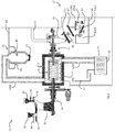
- a waste-to-energy conversion system 1 comprises the following:
- the process plant 1 is for the production of bio-energy and bio-refined chemicals, polymers and fuels and operates on the principle of pyrolysis, a thermal process in which materials thermally decompose in the absence of oxygen.
- the feedstock inlet 10 comprises:
- the hopper feed 80 has a pre-compaction closing device 84, and a plunger 85 for compacting feedstock.
- the hopper 81 has gate valves 90 and 91, allowing a quantity of feedstock to be dropped into an interlock arrangement. Both of the feed hoppers 80 and 81 deliver into the main hopper 82, from which the auger system 83 draws the feedstock and delivers it into the rotating retort drum 4, via the rotating retort drum inlet 65, as illustrated in more detail in Figs 3 to 5 .
- a heat exchange system 30 has the conduit 12(b), for extracting heated flue exhaust gases from the annulus between the muffle furnace shell 3 and the rotating retort drum 4, a heat exchanger 32, and a flue 33. This extracts valuable heat from the gases used to heat the rotating retort drum 4.
- the char recovery system 17 comprises the hopper 16, and a series of two inclined augers 41 and 42 linked by a rotary seal valve 40.
- the lower auger 42 is linked at its output to a secondary char hopper system 43 comprising:
- a pipe 44 delivers char under pneumatic transfer action to the char burner 18.
- the char burner 18 has a pair of tangentially-directed char inlets 45, and a lower gate 46.
- this has an auger for combined delivery of syngas and char out of the retort drum 4. It terminates over the primary char hopper 16, so that syngas rises via a conduit 51 for delivery to the syngas cleaning system 20, and char falls under gravity into the hopper 16.
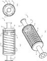
- the rotating retort drum 4 as shown in Figs. 3 to 5 , comprises a cylinder 60, multiple internal helical blades 61 extending inwardly from the cylinder 60 internal surface.
- the in-feed system 83 ensures safe and reliable delivery of feedstock to the rotating retort drum 4, and comprises the following components:
- the rotating retort drum 4 is therefore rotated by the drive mechanism 100 applying drive to the rotating retort drum drive sleeve 65 and supported by the bearings 101.
- the flange 96 allows excellent contact between the drive train 100 and the drive sleeve 65.
- the auger tube 91 extends into the rotating retort drum 4 the feedstock material is deposited directly onto the outer surface wall 60. This immediately allows the heat to be directly transferred from the hot gases in the space around the rotating drum 4 and via the drum corrugated wall 60 to the feedstock F. This may give rise to an undesirable effect of heat being transferred towards the hopper 82, however this effect is minimised by the cooling jacket arrangement 105 and 95. Moreover, there is a risk of syngas escaping through the feedstock within the auger tube 91. However, the potential syngas escape path is blocked by the hopper 82 being kept full and also by the interlocking gate valves 84, 85, 90, and 91, thereby blocking the outer end of the inlet auger system 83.
- the bellows 106 accommodates mutual axial expansion and contraction between the rotating retort drum 4 and the stationary parts of the in-feed spigot and auger system.
- the outlet stage 15 has the rotating retort drum outlet sleeve 66 on bearings 120 and linked via a double ring seal 121 to an expansion bellows 122.
- This allows axial expansion and contraction, and the bearing 120 takes the weight of this side of the retort 4.
- the rotating retort drum 4 sleeve 66 encloses an auger tube 130, in turn housing an auger scroll 131.
- the auger scroll 131 is driven by a motor and gear drive 140 at its outermost end.
- the auger tube 130 has a char outlet opening 142 on its lower side, which allows the char and solid particulate to fall and occupy the lower part of the hopper 16.
- the syngas occupies any free volume remaining in the hopper where it is subsequently extracted under negative pressure through the outlet port 51.
- the fuel feed system 10 ensures uniform input of feedstock into the rotating retort drum 4 without the ingress of air or escape of syngas. This objective is achieved by controlled entry of feedstock through a series of augers and interlocking gate valves. Excluding oxygen prevents combustion of the fuel and ensures that no dioxins can be formed at detectable levels.
- the fuel feed primary hoppers 80 and 81 act as a buffer mechanism to facilitate material accumulation over the auger 93 and thus ensures that the zone in front of the interlocking gate valves 90 and 91 is always occupied.
- the vessel is manufactured from carbon steel with a painted surface finish to the exterior.
- the hopper is mounted in an elevated position to facilitate inclined auger and gate valve alignment and functionality.
- the level control on the hopper 81 is determined by high and low level sensors detecting fill level. In the event of low level alarm activation the gate valves will not function.
- the fuel feed secondary hopper 82 is a trapezoidal shaped temporary storage vessel for the input material prior to feeding it into the rotating retort drum 4 at the appropriate rate and also acts as a buffer zone to allow material to accumulate in front of the rotating retort drum.
- the in-feed hopper 82 is integrated with the screw 93.
- the gate valves 90 and 91 are designed to meet demanding applications when handling a range of feedstock materials ranging from moist organic biomass (to drier non-organic feed-stocks.
- the valves are mounted in a horizontal position which facilitates gravitational flow of material and delivers a positive material shut-off together with gas tight sealing.
- the front end of the in-feed system 10 comprises the in-feed hopper 82 flanged to the in-feed auger 93 and gas seal equipment.
- the in-feed auger 93 feeds through a central axis where the fuel is delivered into the rotating retort drum 4.
- the rotational speed of the auger is controlled by the drive mechanism 100 via a gear train 99 and revolutions per minute are monitored.
- the in-feed system 10 dual pipe configuration in which the fuel enters on the inner tube 91 and is water cooled on the outer tube 95 is very advantageous.
- the in-feed auger 93 has a mounted variable speed drive 90 which controls the feed rate of material to the rotating retort drum 4.
- the auger 93 feeds the material through the central axis of the spigot and the fuel is deposited onto the front section of the rotating retort drum.
- the water jacket 95 that surrounds the fuel feed tube 91 ensures that the fuel is not prematurely pyrolysed prior to entry into the rotating retort drum whilst also delivering suitable water cooling effects onto the steel shell of the spigot.
- the water jacket 95 flow is controlled by an inline centrifugal pump.
- the model selected is an industrial close-coupled capable of appropriate water flow to maintain satisfactory heat transfer levels.
- the bellows 106 are very effective at accommodating any thermal expansion of the rotating retort drum, providing a suitable rotating retort drum expansion allowance has been incorporated into the design which the bellows pieces facilitate.
- the in-feed side of the rotating retort drum has minimal expansion capacity due to the roller design which encourages the thermal expansion to occur on the back end bellows 106.
- the bellows forms part of the spigot design that is water cooled, the operating temperature on the front end expansion bellows is limited.
- the inside of the bellows 106 has the potential to be exposed to syngas derived from selected feedstock materials and therefore will have the potential to contain corrosive gas elements including chlorine and sulphur.
- the material selection for the bellows along with wall thickness will compensate for the potential presence of these elements.
- the gas seals 97 operate effectively as the transitional components between the rotating retort drum 4 tube 65 and the stationary front and rear spigots 98, whilst also absorbing the expansion of the rotating retort drum. Both the front and rear seals are of similar design. Eco-rubber Viton seals are used due to their compatibility with hydrocarbons and their known higher temperature and chemical resistance characteristics. There are two opposed seals to preserve a leak free seal design. The inner seal is arranged to prevent the leakage of syngas from the rotating retort drum to the outside atmosphere under conditions of positive pressure while the outer seal is arranged to prevent the ingress of air from the outside atmosphere into the rotating retort drum under conditions of negative pressure.
- Grease packing is provided in the void between the seals to assist seal lubrication. Seal type and profile and material are critical to the design feature.
- the seal is fitted with a bearing which is provided with its own grease nipple for lubrication.
- Feedstock to be pyrolysed is augured into the retort 4 which is devoid of oxygen.
- Oxygen conditions within the reactor are maintained by controlling an initial purge of the reactor with nitrogen followed by specific control philosophy and system design to eliminate air ingress through the in-feed mechanism.
- the muffle furnace 3 cylindrical stainless steel outer shell 3 with refractory lining allows adequate heat transfer to the rotating retort drum 4 from flue exhaust gases.
- the muffle furnace 3 houses the rotating retort drum 4, which protrudes by the tubes 65 and 66 through both ends of the outer vessel.
- the muffle furnace 3 allows removal of the end plates, which in turn facilitates access to the external surfaces of the rotating retort drum. This subsequently assists in the event of maintenance requirements.
- Figs. 8 to 10 show an alternative retort drum 150 that comprises an outer corrugated shell 151 with internal vanes 152 extending inwardly from the shell 151and an end dish 156. There is additionally an internal dish 153 for guiding delivery of char out of the drum 150.
- the feedstock can have controlled temperature exposure for the optimum period of time, and delivery into the outlet auger is very effective.
- Radial vanes 155 at the outlet end of the drum 150 effectively drop char which is trapped on the vanes 155 and between the drum 150 end dish 156 and the internal dish 153 onto the auger 131. It has been found that by providing spaced apart barriers (153 and drum 150 end 156) in addition to radial barriers (155) there is very effective entrapment of char and delivery into the outlet auger 131.
- the gases (syngas) cleaning system 20 is arranged to receive syngas arising from pyrolysis of the biomass feedstock, such as municipal solid waste (MSW).
- biomass feedstock such as municipal solid waste (MSW).
- the gases (syngas) treatment system 20 comprises a cracking tower 220 which directly receives the syngas from the pyrolysis retort 4 or 150.
- the tower 220 feeds gases (syngas) with smaller molecular chains to a heat exchanger 230 for reduction of temperature, and this in turn feeds the gases to a quench device 231 having a Venturi-like throat for further reduction to meet engine specified temperature ranges.
- the tower may be horizontally arranged rather than vertical, its orientation not being important.
- the gas cracking tower 250 preferably has a length of 2m to 8m, and more preferably 5m to 8m, and a diameter in the range of 1m to 2m, and is designed and manufactured to retain high operating temperatures. It provides a temperature in the range of 850°C to 1250 °C to create a syngas with a composition of methane, hydrogen, and carbon monoxide along with other trace gases.
- the quench device 231 effectively stops the pyrolysis completely and feeds the gases (syngas) into a scrubber tower 252, from which scrubber liquor is delivered by a sump 253 to a water tank 254.
- High pressure pumps 255 are arranged to deliver the water to the quench device 231.
- the gas at entry to the cracking tower 220 may be at approximately 600°C +/- 50 °C, and due to residence in the tower 220 this rises to a value in the range of 850°C to 1250°C. It is cooled to about 900°C (for a level of 1150°C) by the heat exchanger 230, and the quenching system 231 drops it down to about 100°C.
- the gases (syngas) flow upwardly through the scrubber tower 252 and thence through an outlet 256.
- a portion of the gases (syngas) at this stage is diverted for pyrolysis retort heating, and the main portion is routed to a demister unit 260 and filter unit 257 which provides the output product, cleaned syngas, at an outlet 258.
- the filter system 257 has a flare to ensure safe process operation. It disposes of purged, noncondensable, vented and unused gases from the pyrolysis unit.
- the flare provides a mechanism for safe disposal of the vapour streams by combustion under controlled conditions.
- the pump 259 is managed by a programmed controller with digital processors which receives pressure-sensing signals from various parts of the system, including the retort 4, the gas outlet 15, and the cracking tower 220.
- This is to allow pressure control to ensure that the pressure generated in the retort 4 by conversion of solid mass feedstock to gas is capped at a level which does not become excessive, and is preferably in the range of -20 mBar to +20 mBar within the rotating retort 4, and more preferably -5 mBar to 0 mBar.
- this also controls the residence time in the cracking tower 220, to a value in the range of 1second to 4seconds.
- the pressure control helps to ensure the appropriate residence time in the cracking tower 220. This achieves optimum time for breakdown of the gases to shorter chains with a temperature in the region of 850°C to 1250°C maintained.
- the cracking tower 220 is preheated and maintained at the optimum temperature using pressure and temperature control parameters, and ensures that the syngas distribution and rates of reaction are appropriate given the type of syngas that is presented from the retort.
- booster fan 259 chambers are cast in aluminum alloy and manufactured to eliminate porosity. Impellers are also cast in aluminum and are dynamically balanced to cut down noise and vibration. Booster fan bearing housings are manufactured in cast iron for mechanical stability and each fan chamber assembly is sealed for gas tightness.
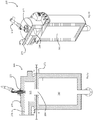
- the tower 220 comprises a combustion chamber 270 having a volume 271 into which extends a pilot burner 272 and an air manifold with multiple injection points 273.
- the syngas is received via a flanged inlet 274.
- the cracking tower 220 is manufactured with a 3mm rolled mild steel outer housing lined with high grade refractory.
- the inlet ducting from the hot char recovery hopper to the cracking tower 220 and the outlet ducting from the cracking tower 220 to the scrubber tower 252 are also lined with high grade refractory.
- Refractory lining consists of either Arelcrete refractory or a combination of Arelcrete refractory and calcium silicate board.
- the gases (syngas) from the combustion chamber 270 are then drawn through a residence chamber 281.
- the pilot burner 272 provides a plume which extends through the combustion chamber 270 towards a choke ring aperture 284. This flame heats the combustion chamber 270 volume 271 and the residence chamber 281 to a temperature in the range of 850°C to 1250°C.
- the tangential flow of the inlet syngas into the gas cracking tower 250 preferably has a length of 2m to 8m, and more preferably 5m to 8m, and a diameter in the range of 1m to 2m, and is designed and manufactured to retain high operating temperatures. It provides a temperature in the range of 850°C to 1250 °C to create a syngas with a composition of methane, hydrogen, and carbon monoxide along with other trace gases.
- the combustion chamber 270 oxidises some of the syngas, thereby losing a small percentage, circa 5%, of the syngas in order to sustain thermal energy requirements of the residence chamber 281.
- the heat level within the residence chamber 281 causes long chain hydrocarbons, in the form of pyrolysis tars and oils to break into shorter chain hydrocarbon gases (syngas), thus eliminating oils and tars.
- the syngas which leaves the residence chamber 281 is fed into the scrubber tower 252 at an inlet 290 of a hot syngas quench unit 231 via the heat exchanger 230 (or boiler arrangement).
- the hot syngas travels through a Venturi quench throat 291 and on into a conduit 292.
- Further quench water is provided by a high pressure spray bar 293 along the centre of the conduit 292.
- Quenched syngas from the conduit 292 enters the scrubber tower 252, which has a tubular housing 300 with flanges 301 joining tubular sections.
- a spray bar 305 extends up through the centre of the scrubber tower 252 for further gas quenching. Syngas exits through an outlet 310, and water drops to a sump 302 having an outlet port 325.
- the water is pumped to the tank 254, and water is drawn from the tank 254 by the pumps 255 to be fed back to the scrubber tower 252.
- the scrubber outlet syngas is fed through the demister 256 and the filter unit 257, and from there to the clean gas outlet 258.
- the major components removed from the syngas by the scrubber tower 252 are water soluble contaminants. There may be pH adjustment in the tank 254 by addition of a neutralizing agent.
- Char consists of carbon and ash, commonly called “charcoal” or “biochar”.
- charcoal or “biochar”.
- a thermochemical fuel cracking process takes place that generates a syngas incorporating the reforming of hydrocarbons, and also produces char (carbon and ash). Any inert material that may be embedded in the fuel will remain with the char.
- the stainless steel char recovery hopper sufficiently lagged with insulating material to maintain high temperature in this vessel, allows for the solid residues to be gravitationally separated from the gaseous residues.
- the newlyformed hot char deposits on the bottom of the vessel where a cooling jacketed extract auger facilitates removal and deposition of hot char into a char recovery storage vessel.
- syngas is removed through the top of the vessel where temperatures remain high.
- This syngas is subsequently ducted into the gas cracking tower 220, with a bypass spur to the gas vent valve, to crack pyrolysis tars and oils entrained in the syngas stream into shorter chain hydrocarbon gases.
- pyrolysis tars and oils are viewed as contaminants.
- the rotating retort drum 4 preferably operates at a temperature of about 850°C ⁇ 100°C whereby a thermochemical reaction takes place called "cracking" of hydrocarbons.
- the solid materials are converted into gases, oils and char. Given the operating temperatures, the gases are reformed into short hydrocarbon chain gases, with release of chlorine, sulphur and other contaminants that turn gaseous below about 900°C. As no oxygen is present in the reactor 4 no combustion takes place and dioxins and furans cannot be formed at detectable levels.
- the computerised control system manages the operating parameters including the temperature, pressures and level control within this oxygen-free environment.
- the syngas produced in the pyrolysis retort 4 is a mixture of light gases, heavier gases and condensable organics.
- the light gases, which comprise the main fraction, include hydrogen, carbon monoxide, carbon dioxide, methane and ethane and similar short chain hydrocarbons.
- the rotating retort drum 4 vanes progressively advance the feedstock as the drum 4 rotates. This ensures maximum fuel residence time, uniform radial constant heat exposure and minimal shell stress while the fuel is converted into two products: a syngas and, char (charcoal) at an optimum rate.
- the outer shell 60 of the rotating retort drum 4 has a corrugated profile which maximizes heat absorbing surface area by increasing it in excess of 50%. The corrugations allow the wall thickness of the shell to be reduced without compromising the vessel's structural integrity.
- the vane 61 arrangement encourages agitation of the feedstock within the vessel as it rotates and progressively advances towards the back-end extraction point.
- the hot flue exhaust gases delivered by the conduit 12(a) heat the rotating retort drum 4 on all surfaces, which then radiates towards the centre of the chamber, imparting its heat to the feedstock.
- the pyrolysis chamber 4 and the complete gas circuit can be injected with nitrogen in the event of it being necessary to purge out syngas or air.
- a gas venting system at the outlet of the rotating retort drum 4 releases syngas to atmosphere in the event of system overpressure.
- the gas pressure in the rotating retort drum 4 is controlled by the gas booster fan 259, which either increases velocity to reduce pressure or reduces velocity to increase pressure within a defined operational range.
- Fuel is thermally decomposed into a carbon monoxide, carbon dioxide, methane and hydrogen gas stream called syngas. Another output from the thermal conversion process is the carbon char fraction of the feedstock. This product will be cooled and temporarily stored prior to further analysis or treatment.
- the rotating retort drum 4 inlet and outlet stub pipes 65 and 66 extend from the dished ends of the rotating retort drum.
- Trunnion wheels 101 and 120 are mounted to each of the stub pipes 65 and 66 respectively, which in turn sit on rollers fixed to cradles.
- the rollers and trunnion wheels are manufactured to assist ease of retort drum rotation while allowing for expansion of the vessel, at its extract end, during normal operating conditions.
- the drive mechanism 100 ensures consistent rotational speed of the rotating retort drum 4 which determines the residence time for the feedstock to be exposed to the thermal cracking atmosphere as it is progressed through the drum by the vanes 61.
- the drive mechanism 100 overcomes the torque threshold of the gas seals and friction associated with the rollers.
- the solid char and syngas extraction system 15 includes an out-feed spigot, expansion bellows 106 and 122, stainless steel out-feed scroll 131 and a gas seal rotary housing with integrated bearing assembly which is water cooled. This system is flanged to the rotating retort drum and the stainless steel char recovery hopper.
- the out-feed scroll 131 has a mounted variable speed drive 140 which controls char extraction from the rotating retort drum.
- the scroll 131 extracts this pyrolysed material through the central axis of the out-feed spigot 130 and the solid char is deposited into the stainless steel char recovery vessel 16, whilst syngas is extracted under negative pressure and ducted via the tube 51 into the gas cracking tower 220.
- the two bellows pieces 106 and 122 accommodate thermal expansion of the rotating retort drum 4.
- the newly formed hot char that has been extracted from the rotating retort drum 4 is directed into the inlet of the inclined char cooling extract auger 41 located at the base of the stainless steel char recovery hopper 16.
- the auger 41 consists of a water-jacketed outer body that is inclined at an angle to ensure full occupancy of the auger diameter to maximize cooling potential and deliver a gas seal.
- the exit of the auger has two interlocking gate valves to ensure a gas seal is maintained and are of similar design to the front-end interlocking valves. Both gates valves are horizontally mounted and sequentially controlled whereby only one valve is open at any given time. These gates valves can be exchanged for rotary valve depending on material types and its ability to flow through the valve body.
- the water-cooled propane heating lance 272 enables initial heating of the cracking tower in the chamber 270.
- the air manifold and nozzles 273 are utilized to increase the temperature of the incoming syngas from circa 500°C to a value in the range of 850°C 1250°C.
- the major advantages of the cracking tower 220 are that a residence time, in the range of 1 to 4 seconds is achieved, sufficient for long hydrocarbon chains to be converted to shorter chains whilst avoiding the carryover of tar.
- High efficiency hot gas filtration incorporating ceramic filters 257 is an important aspect in the gas conditioning process. Subject to feedstock composition and process parameters, the pyrolysis conversion process produces a wide range of particulate emissions which are particularly suited to capture by means of filtration.
- Traditional bag filters are largely unsuitable for the process because of their poor thermal durability and inherent flammability whereas ceramic filters typically operate at higher temperatures and have greater face velocities than bag filters.
- the filtration system 257 operates as follows:
- the invention is not limited to the embodiments described but may be varied in construction and detail.
- the system may be arranged to treat gases from any process, not necessarily syngas.
Applications Claiming Priority (3)
| Application Number | Priority Date | Filing Date | Title |
|---|---|---|---|
| EP16163814 | 2016-04-05 | ||
| EP16163815 | 2016-04-05 | ||
| PCT/EP2017/057978 WO2017174574A1 (en) | 2016-04-05 | 2017-04-04 | A waste-to-energy conversion system |
Publications (2)
| Publication Number | Publication Date |
|---|---|
| EP3440161A1 EP3440161A1 (en) | 2019-02-13 |
| EP3440161B1 true EP3440161B1 (en) | 2021-11-10 |
Family
ID=58489012
Family Applications (1)
| Application Number | Title | Priority Date | Filing Date |
|---|---|---|---|
| EP17715474.7A Active EP3440161B1 (en) | 2016-04-05 | 2017-04-04 | A waste-to-energy conversion system and method |
Country Status (4)
| Country | Link |
|---|---|
| US (2) | US10889771B2 (zh) |
| EP (1) | EP3440161B1 (zh) |
| CN (1) | CN109153928A (zh) |
| WO (1) | WO2017174574A1 (zh) |
Family Cites Families (18)
| Publication number | Priority date | Publication date | Assignee | Title |
|---|---|---|---|---|
| US4347119A (en) * | 1980-11-21 | 1982-08-31 | Thomas Delbert D | Horizontal oil shale and tar sands retort |
| US4412889A (en) * | 1982-03-22 | 1983-11-01 | Kleenair Products Co., Inc. | Pyrolysis reaction apparatus |
| DE4237161C2 (de) | 1992-11-04 | 1995-11-30 | Ellinghaus Umweltschutzanlagen | Vorrichtung zum Aufbereiten von aluminiumhaltigen Materialien |
| DE4327953A1 (de) * | 1993-08-19 | 1995-02-23 | Siemens Ag | Anlage zur thermischen Abfallentsorgung sowie Verfahren zum Betrieb einer solchen Anlage |
| NL1007710C2 (nl) * | 1997-12-05 | 1999-06-08 | Gibros Pec Bv | Werkwijze voor het verwerken van afval- respectievelijk biomassamateriaal. |
| JP4154029B2 (ja) * | 1998-04-07 | 2008-09-24 | 株式会社東芝 | 廃棄物の処理方法および廃棄物処理装置 |
| US20070186829A1 (en) * | 2003-08-21 | 2007-08-16 | International Environmental Solutions Corporation | Variable speed pyrolytic waste treatment system |
| AU2004268209B2 (en) * | 2003-08-21 | 2009-06-11 | International Environmental Solutions Corporation | Chamber support for pyrolytic waste treatment system |
| US8833276B2 (en) * | 2009-02-06 | 2014-09-16 | William Hunkyun Bang | Burner system for waste plastic fuel |
| US8328993B2 (en) * | 2009-05-18 | 2012-12-11 | Greenlight Energy Solutions, Llc | Pyrolysis reactor for processing municipal wastes |
| EP2665803B1 (en) * | 2011-01-23 | 2020-03-25 | Pike Enterprises, LLC | Self-sustaining pyrolysis system for energy production |
| US8715402B2 (en) * | 2011-03-22 | 2014-05-06 | Mitsubishi Heavy Industries, Ltd. | Air pollution control system and air pollution control method, spray drying device of dewatering filtration fluid from desulfurization discharged water, and method thereof |
| CN102363729A (zh) * | 2011-09-07 | 2012-02-29 | 杜克镛 | 秸秆炭化炉 |
| CN102433144B (zh) * | 2011-10-29 | 2013-12-18 | 大连天润能源技术开发有限公司 | 一种油砂、油母页岩综合利用方法及其设备 |
| CN102492509A (zh) * | 2011-12-22 | 2012-06-13 | 山东农业大学 | 自动控温连续生产生物炭的工艺和设备 |
| US20140150650A1 (en) * | 2012-12-03 | 2014-06-05 | New England Wood Pellet Llc | Gas-To-Liquid Heat Exchanger and Gas Particulate Scrubber |
| CN204079889U (zh) * | 2014-08-19 | 2015-01-07 | 广东天源环境科技有限公司 | 一种有机固体废物处理的热解设备 |
| US9052109B1 (en) * | 2014-12-12 | 2015-06-09 | Infinitus Renewable Energy, LLC | Pyrolytic gas processor and tire conversion system therefrom |
-
2017
- 2017-04-04 CN CN201780029282.XA patent/CN109153928A/zh active Pending
- 2017-04-04 EP EP17715474.7A patent/EP3440161B1/en active Active
- 2017-04-04 US US16/090,782 patent/US10889771B2/en active Active
- 2017-04-04 WO PCT/EP2017/057978 patent/WO2017174574A1/en active Application Filing
-
2020
- 2020-12-17 US US17/124,759 patent/US11661560B2/en active Active
Non-Patent Citations (1)
| Title |
|---|
| None * |
Also Published As
| Publication number | Publication date |
|---|---|
| WO2017174574A1 (en) | 2017-10-12 |
| US20190119588A1 (en) | 2019-04-25 |
| US11661560B2 (en) | 2023-05-30 |
| CN109153928A (zh) | 2019-01-04 |
| EP3440161A1 (en) | 2019-02-13 |
| US10889771B2 (en) | 2021-01-12 |
| US20210102131A1 (en) | 2021-04-08 |
Similar Documents
| Publication | Publication Date | Title |
|---|---|---|
| CN107120656B (zh) | 一种间接热裂解及灰渣燃烧熔融炉及其处理方法 | |
| ES2343167T3 (es) | Gasificador de multiples facetas y procedimientos relacionados. | |
| RU2393200C2 (ru) | Способ термической переработки твердых органических отходов и установка для его осуществления | |
| PT1012215E (pt) | Aparelho reactor de gaseificação | |
| BRPI1000208A2 (pt) | equipamento trocador de calor vibrante para conversão de baixa temperatura para tratamento de resìduos orgánicos e processo de tratamento de resìduos orgánicos mediante emprego de equipamento trocador de calor vibrante para conversão de baixa temperatura | |
| NO312260B1 (no) | Fremgangsmåte og innretning for konvertering av energi ved forbrenning av fast brennstoff | |
| US10428277B2 (en) | Device for processing scrap rubber | |
| US11959037B2 (en) | System and processes for upgrading synthetic gas produced from waste materials, municipal solid waste or biomass | |
| PL191219B1 (pl) | Sposób i urządzenie do pirolizy i zgazowania materiałów odpadowych | |
| US11661560B2 (en) | Waste-to-energy conversion system | |
| CN109943357A (zh) | 一种含油废弃物多级裂解处理方法与设备 | |
| WO2014090574A1 (en) | Thermal processing system having an auger arrangement and method using it | |
| RU2408819C1 (ru) | Установка для переработки твердых органических отходов | |
| WO2013088105A1 (en) | Thermal processing system | |
| IE20170070A1 (en) | A waste to energy conversion system | |
| RU2678215C1 (ru) | Пиролизная мусоросжигательная установка | |
| RU207663U1 (ru) | Мобильный модуль реактора пиролиза для комплексов термической переработки отходов | |
| CN106675592B (zh) | 一种间接热脱附炭化装置及处理方法 | |
| WO2014207755A1 (en) | Zero effluent discharge biomass gasification | |
| WO2015179881A1 (en) | Gasification and pyrolysis optimization system for medical and toxic waste | |
| CN104501173A (zh) | 一种化工类固废、废液热解处理装置及工艺 | |
| EP0532901B1 (en) | Method and plant to gasify solid fuels containing non-combustible meltable materials | |
| DE102007017859A1 (de) | Vergaser | |
| CN114440222A (zh) | 一种有机固废热解系统及方法 | |
| CN113166661A (zh) | 用于气化和/或熔化原料的反应器和工艺 |
Legal Events
| Date | Code | Title | Description |
|---|---|---|---|
| STAA | Information on the status of an ep patent application or granted ep patent |
Free format text: STATUS: UNKNOWN |
|
| STAA | Information on the status of an ep patent application or granted ep patent |
Free format text: STATUS: THE INTERNATIONAL PUBLICATION HAS BEEN MADE |
|
| PUAI | Public reference made under article 153(3) epc to a published international application that has entered the european phase |
Free format text: ORIGINAL CODE: 0009012 |
|
| STAA | Information on the status of an ep patent application or granted ep patent |
Free format text: STATUS: REQUEST FOR EXAMINATION WAS MADE |
|
| 17P | Request for examination filed |
Effective date: 20181009 |
|
| AK | Designated contracting states |
Kind code of ref document: A1 Designated state(s): AL AT BE BG CH CY CZ DE DK EE ES FI FR GB GR HR HU IE IS IT LI LT LU LV MC MK MT NL NO PL PT RO RS SE SI SK SM TR |
|
| AX | Request for extension of the european patent |
Extension state: BA ME |
|
| DAV | Request for validation of the european patent (deleted) | ||
| DAX | Request for extension of the european patent (deleted) | ||
| STAA | Information on the status of an ep patent application or granted ep patent |
Free format text: STATUS: EXAMINATION IS IN PROGRESS |
|
| 17Q | First examination report despatched |
Effective date: 20200918 |
|
| STAA | Information on the status of an ep patent application or granted ep patent |
Free format text: STATUS: EXAMINATION IS IN PROGRESS |
|
| GRAP | Despatch of communication of intention to grant a patent |
Free format text: ORIGINAL CODE: EPIDOSNIGR1 |
|
| STAA | Information on the status of an ep patent application or granted ep patent |
Free format text: STATUS: GRANT OF PATENT IS INTENDED |
|
| INTG | Intention to grant announced |
Effective date: 20210702 |
|
| GRAS | Grant fee paid |
Free format text: ORIGINAL CODE: EPIDOSNIGR3 |
|
| GRAA | (expected) grant |
Free format text: ORIGINAL CODE: 0009210 |
|
| STAA | Information on the status of an ep patent application or granted ep patent |
Free format text: STATUS: THE PATENT HAS BEEN GRANTED |
|
| AK | Designated contracting states |
Kind code of ref document: B1 Designated state(s): AL AT BE BG CH CY CZ DE DK EE ES FI FR GB GR HR HU IE IS IT LI LT LU LV MC MK MT NL NO PL PT RO RS SE SI SK SM TR |
|
| REG | Reference to a national code |
Ref country code: GB Ref legal event code: FG4D |
|
| REG | Reference to a national code |
Ref country code: AT Ref legal event code: REF Ref document number: 1446094 Country of ref document: AT Kind code of ref document: T Effective date: 20211115 Ref country code: CH Ref legal event code: EP |
|
| REG | Reference to a national code |
Ref country code: DE Ref legal event code: R096 Ref document number: 602017049069 Country of ref document: DE |
|
| REG | Reference to a national code |
Ref country code: IE Ref legal event code: FG4D |
|
| REG | Reference to a national code |
Ref country code: LT Ref legal event code: MG9D |
|
| REG | Reference to a national code |
Ref country code: NL Ref legal event code: MP Effective date: 20211110 |
|
| REG | Reference to a national code |
Ref country code: AT Ref legal event code: MK05 Ref document number: 1446094 Country of ref document: AT Kind code of ref document: T Effective date: 20211110 |
|
| PG25 | Lapsed in a contracting state [announced via postgrant information from national office to epo] |
Ref country code: RS Free format text: LAPSE BECAUSE OF FAILURE TO SUBMIT A TRANSLATION OF THE DESCRIPTION OR TO PAY THE FEE WITHIN THE PRESCRIBED TIME-LIMIT Effective date: 20211110 Ref country code: LT Free format text: LAPSE BECAUSE OF FAILURE TO SUBMIT A TRANSLATION OF THE DESCRIPTION OR TO PAY THE FEE WITHIN THE PRESCRIBED TIME-LIMIT Effective date: 20211110 Ref country code: FI Free format text: LAPSE BECAUSE OF FAILURE TO SUBMIT A TRANSLATION OF THE DESCRIPTION OR TO PAY THE FEE WITHIN THE PRESCRIBED TIME-LIMIT Effective date: 20211110 Ref country code: BG Free format text: LAPSE BECAUSE OF FAILURE TO SUBMIT A TRANSLATION OF THE DESCRIPTION OR TO PAY THE FEE WITHIN THE PRESCRIBED TIME-LIMIT Effective date: 20220210 Ref country code: AT Free format text: LAPSE BECAUSE OF FAILURE TO SUBMIT A TRANSLATION OF THE DESCRIPTION OR TO PAY THE FEE WITHIN THE PRESCRIBED TIME-LIMIT Effective date: 20211110 |
|
| PG25 | Lapsed in a contracting state [announced via postgrant information from national office to epo] |
Ref country code: IS Free format text: LAPSE BECAUSE OF FAILURE TO SUBMIT A TRANSLATION OF THE DESCRIPTION OR TO PAY THE FEE WITHIN THE PRESCRIBED TIME-LIMIT Effective date: 20220310 Ref country code: SE Free format text: LAPSE BECAUSE OF FAILURE TO SUBMIT A TRANSLATION OF THE DESCRIPTION OR TO PAY THE FEE WITHIN THE PRESCRIBED TIME-LIMIT Effective date: 20211110 Ref country code: PT Free format text: LAPSE BECAUSE OF FAILURE TO SUBMIT A TRANSLATION OF THE DESCRIPTION OR TO PAY THE FEE WITHIN THE PRESCRIBED TIME-LIMIT Effective date: 20220310 Ref country code: PL Free format text: LAPSE BECAUSE OF FAILURE TO SUBMIT A TRANSLATION OF THE DESCRIPTION OR TO PAY THE FEE WITHIN THE PRESCRIBED TIME-LIMIT Effective date: 20211110 Ref country code: NO Free format text: LAPSE BECAUSE OF FAILURE TO SUBMIT A TRANSLATION OF THE DESCRIPTION OR TO PAY THE FEE WITHIN THE PRESCRIBED TIME-LIMIT Effective date: 20220210 Ref country code: NL Free format text: LAPSE BECAUSE OF FAILURE TO SUBMIT A TRANSLATION OF THE DESCRIPTION OR TO PAY THE FEE WITHIN THE PRESCRIBED TIME-LIMIT Effective date: 20211110 Ref country code: LV Free format text: LAPSE BECAUSE OF FAILURE TO SUBMIT A TRANSLATION OF THE DESCRIPTION OR TO PAY THE FEE WITHIN THE PRESCRIBED TIME-LIMIT Effective date: 20211110 Ref country code: HR Free format text: LAPSE BECAUSE OF FAILURE TO SUBMIT A TRANSLATION OF THE DESCRIPTION OR TO PAY THE FEE WITHIN THE PRESCRIBED TIME-LIMIT Effective date: 20211110 Ref country code: GR Free format text: LAPSE BECAUSE OF FAILURE TO SUBMIT A TRANSLATION OF THE DESCRIPTION OR TO PAY THE FEE WITHIN THE PRESCRIBED TIME-LIMIT Effective date: 20220211 Ref country code: ES Free format text: LAPSE BECAUSE OF FAILURE TO SUBMIT A TRANSLATION OF THE DESCRIPTION OR TO PAY THE FEE WITHIN THE PRESCRIBED TIME-LIMIT Effective date: 20211110 |
|
| PG25 | Lapsed in a contracting state [announced via postgrant information from national office to epo] |
Ref country code: SM Free format text: LAPSE BECAUSE OF FAILURE TO SUBMIT A TRANSLATION OF THE DESCRIPTION OR TO PAY THE FEE WITHIN THE PRESCRIBED TIME-LIMIT Effective date: 20211110 Ref country code: SK Free format text: LAPSE BECAUSE OF FAILURE TO SUBMIT A TRANSLATION OF THE DESCRIPTION OR TO PAY THE FEE WITHIN THE PRESCRIBED TIME-LIMIT Effective date: 20211110 Ref country code: RO Free format text: LAPSE BECAUSE OF FAILURE TO SUBMIT A TRANSLATION OF THE DESCRIPTION OR TO PAY THE FEE WITHIN THE PRESCRIBED TIME-LIMIT Effective date: 20211110 Ref country code: EE Free format text: LAPSE BECAUSE OF FAILURE TO SUBMIT A TRANSLATION OF THE DESCRIPTION OR TO PAY THE FEE WITHIN THE PRESCRIBED TIME-LIMIT Effective date: 20211110 Ref country code: DK Free format text: LAPSE BECAUSE OF FAILURE TO SUBMIT A TRANSLATION OF THE DESCRIPTION OR TO PAY THE FEE WITHIN THE PRESCRIBED TIME-LIMIT Effective date: 20211110 Ref country code: CZ Free format text: LAPSE BECAUSE OF FAILURE TO SUBMIT A TRANSLATION OF THE DESCRIPTION OR TO PAY THE FEE WITHIN THE PRESCRIBED TIME-LIMIT Effective date: 20211110 |
|
| REG | Reference to a national code |
Ref country code: DE Ref legal event code: R097 Ref document number: 602017049069 Country of ref document: DE |
|
| PLBE | No opposition filed within time limit |
Free format text: ORIGINAL CODE: 0009261 |
|
| STAA | Information on the status of an ep patent application or granted ep patent |
Free format text: STATUS: NO OPPOSITION FILED WITHIN TIME LIMIT |
|
| 26N | No opposition filed |
Effective date: 20220811 |
|
| PG25 | Lapsed in a contracting state [announced via postgrant information from national office to epo] |
Ref country code: AL Free format text: LAPSE BECAUSE OF FAILURE TO SUBMIT A TRANSLATION OF THE DESCRIPTION OR TO PAY THE FEE WITHIN THE PRESCRIBED TIME-LIMIT Effective date: 20211110 |
|
| PG25 | Lapsed in a contracting state [announced via postgrant information from national office to epo] |
Ref country code: SI Free format text: LAPSE BECAUSE OF FAILURE TO SUBMIT A TRANSLATION OF THE DESCRIPTION OR TO PAY THE FEE WITHIN THE PRESCRIBED TIME-LIMIT Effective date: 20211110 |
|
| REG | Reference to a national code |
Ref country code: CH Ref legal event code: PL |
|
| REG | Reference to a national code |
Ref country code: BE Ref legal event code: MM Effective date: 20220430 |
|
| PG25 | Lapsed in a contracting state [announced via postgrant information from national office to epo] |
Ref country code: MC Free format text: LAPSE BECAUSE OF FAILURE TO SUBMIT A TRANSLATION OF THE DESCRIPTION OR TO PAY THE FEE WITHIN THE PRESCRIBED TIME-LIMIT Effective date: 20211110 Ref country code: LU Free format text: LAPSE BECAUSE OF NON-PAYMENT OF DUE FEES Effective date: 20220404 Ref country code: LI Free format text: LAPSE BECAUSE OF NON-PAYMENT OF DUE FEES Effective date: 20220430 Ref country code: CH Free format text: LAPSE BECAUSE OF NON-PAYMENT OF DUE FEES Effective date: 20220430 |
|
| PG25 | Lapsed in a contracting state [announced via postgrant information from national office to epo] |
Ref country code: BE Free format text: LAPSE BECAUSE OF NON-PAYMENT OF DUE FEES Effective date: 20220430 |
|
| PGFP | Annual fee paid to national office [announced via postgrant information from national office to epo] |
Ref country code: IE Payment date: 20230313 Year of fee payment: 7 Ref country code: FR Payment date: 20230329 Year of fee payment: 7 |
|
| PG25 | Lapsed in a contracting state [announced via postgrant information from national office to epo] |
Ref country code: IT Free format text: LAPSE BECAUSE OF FAILURE TO SUBMIT A TRANSLATION OF THE DESCRIPTION OR TO PAY THE FEE WITHIN THE PRESCRIBED TIME-LIMIT Effective date: 20211110 |
|
| PGFP | Annual fee paid to national office [announced via postgrant information from national office to epo] |
Ref country code: GB Payment date: 20230313 Year of fee payment: 7 |
|
| P01 | Opt-out of the competence of the unified patent court (upc) registered |
Effective date: 20230327 |
|
| PGFP | Annual fee paid to national office [announced via postgrant information from national office to epo] |
Ref country code: DE Payment date: 20230403 Year of fee payment: 7 |
|
| PG25 | Lapsed in a contracting state [announced via postgrant information from national office to epo] |
Ref country code: HU Free format text: LAPSE BECAUSE OF FAILURE TO SUBMIT A TRANSLATION OF THE DESCRIPTION OR TO PAY THE FEE WITHIN THE PRESCRIBED TIME-LIMIT; INVALID AB INITIO Effective date: 20170404 |
|
| PG25 | Lapsed in a contracting state [announced via postgrant information from national office to epo] |
Ref country code: MK Free format text: LAPSE BECAUSE OF FAILURE TO SUBMIT A TRANSLATION OF THE DESCRIPTION OR TO PAY THE FEE WITHIN THE PRESCRIBED TIME-LIMIT Effective date: 20211110 Ref country code: CY Free format text: LAPSE BECAUSE OF FAILURE TO SUBMIT A TRANSLATION OF THE DESCRIPTION OR TO PAY THE FEE WITHIN THE PRESCRIBED TIME-LIMIT Effective date: 20211110 |