EP3439613B1 - Apparatus and method for improved drug regimen compliance - Google Patents
Apparatus and method for improved drug regimen compliance Download PDFInfo
- Publication number
- EP3439613B1 EP3439613B1 EP17719957.7A EP17719957A EP3439613B1 EP 3439613 B1 EP3439613 B1 EP 3439613B1 EP 17719957 A EP17719957 A EP 17719957A EP 3439613 B1 EP3439613 B1 EP 3439613B1
- Authority
- EP
- European Patent Office
- Prior art keywords
- electrode
- blister card
- detection module
- sensor
- tablet
- Prior art date
- Legal status (The legal status is an assumption and is not a legal conclusion. Google has not performed a legal analysis and makes no representation as to the accuracy of the status listed.)
- Active
Links
- 238000000034 method Methods 0.000 title claims description 39
- 239000003814 drug Substances 0.000 title description 24
- 229940079593 drug Drugs 0.000 title description 22
- 238000001514 detection method Methods 0.000 claims description 147
- 239000003990 capacitor Substances 0.000 claims description 24
- 238000012544 monitoring process Methods 0.000 claims description 19
- 230000008878 coupling Effects 0.000 claims description 3
- 238000010168 coupling process Methods 0.000 claims description 3
- 238000005859 coupling reaction Methods 0.000 claims description 3
- 230000000977 initiatory effect Effects 0.000 claims 1
- 239000000758 substrate Substances 0.000 description 57
- 239000006187 pill Substances 0.000 description 26
- 229940023488 pill Drugs 0.000 description 17
- 230000008859 change Effects 0.000 description 11
- 238000005516 engineering process Methods 0.000 description 11
- 230000036039 immunity Effects 0.000 description 11
- 239000000463 material Substances 0.000 description 9
- 238000013459 approach Methods 0.000 description 7
- 230000036541 health Effects 0.000 description 5
- 230000010354 integration Effects 0.000 description 5
- 230000003287 optical effect Effects 0.000 description 5
- 238000004806 packaging method and process Methods 0.000 description 5
- 208000035432 Unintended pregnancy Diseases 0.000 description 4
- 239000004020 conductor Substances 0.000 description 4
- 239000003433 contraceptive agent Substances 0.000 description 4
- 230000002254 contraceptive effect Effects 0.000 description 4
- 238000013461 design Methods 0.000 description 4
- 239000011888 foil Substances 0.000 description 4
- 230000006872 improvement Effects 0.000 description 4
- 229940127234 oral contraceptive Drugs 0.000 description 4
- 239000003539 oral contraceptive agent Substances 0.000 description 4
- 239000000243 solution Substances 0.000 description 4
- 239000004696 Poly ether ether ketone Substances 0.000 description 3
- 239000004642 Polyimide Substances 0.000 description 3
- 230000000694 effects Effects 0.000 description 3
- 238000005259 measurement Methods 0.000 description 3
- 230000015654 memory Effects 0.000 description 3
- -1 poly(methylacrylate) Polymers 0.000 description 3
- 229920002530 polyetherether ketone Polymers 0.000 description 3
- 229920001721 polyimide Polymers 0.000 description 3
- 229920000642 polymer Polymers 0.000 description 3
- 229920002981 polyvinylidene fluoride Polymers 0.000 description 3
- 238000012545 processing Methods 0.000 description 3
- 239000002033 PVDF binder Substances 0.000 description 2
- 208000031271 Unwanted pregnancy Diseases 0.000 description 2
- 229910052782 aluminium Inorganic materials 0.000 description 2
- XAGFODPZIPBFFR-UHFFFAOYSA-N aluminium Chemical compound [Al] XAGFODPZIPBFFR-UHFFFAOYSA-N 0.000 description 2
- 230000003466 anti-cipated effect Effects 0.000 description 2
- 230000008901 benefit Effects 0.000 description 2
- 230000006835 compression Effects 0.000 description 2
- 238000007906 compression Methods 0.000 description 2
- 238000010586 diagram Methods 0.000 description 2
- 238000003306 harvesting Methods 0.000 description 2
- 238000007726 management method Methods 0.000 description 2
- 238000004519 manufacturing process Methods 0.000 description 2
- 230000027758 ovulation cycle Effects 0.000 description 2
- 229920000728 polyester Polymers 0.000 description 2
- 229920002635 polyurethane Polymers 0.000 description 2
- 239000004814 polyurethane Substances 0.000 description 2
- 230000001850 reproductive effect Effects 0.000 description 2
- 230000004044 response Effects 0.000 description 2
- 238000009450 smart packaging Methods 0.000 description 2
- 230000001954 sterilising effect Effects 0.000 description 2
- 238000004659 sterilization and disinfection Methods 0.000 description 2
- 208000017667 Chronic Disease Diseases 0.000 description 1
- 229920002319 Poly(methyl acrylate) Polymers 0.000 description 1
- 230000009471 action Effects 0.000 description 1
- 230000004913 activation Effects 0.000 description 1
- 230000001154 acute effect Effects 0.000 description 1
- 238000003491 array Methods 0.000 description 1
- 230000006399 behavior Effects 0.000 description 1
- 230000005540 biological transmission Effects 0.000 description 1
- 230000015572 biosynthetic process Effects 0.000 description 1
- 239000002775 capsule Substances 0.000 description 1
- 230000001413 cellular effect Effects 0.000 description 1
- 238000004891 communication Methods 0.000 description 1
- 230000001010 compromised effect Effects 0.000 description 1
- 238000009223 counseling Methods 0.000 description 1
- 230000001419 dependent effect Effects 0.000 description 1
- 230000000994 depressogenic effect Effects 0.000 description 1
- 230000023077 detection of light stimulus Effects 0.000 description 1
- 238000011161 development Methods 0.000 description 1
- 239000003989 dielectric material Substances 0.000 description 1
- 238000009826 distribution Methods 0.000 description 1
- 238000002593 electrical impedance tomography Methods 0.000 description 1
- 239000012777 electrically insulating material Substances 0.000 description 1
- 230000007613 environmental effect Effects 0.000 description 1
- 238000007667 floating Methods 0.000 description 1
- 239000007897 gelcap Substances 0.000 description 1
- 238000003384 imaging method Methods 0.000 description 1
- 238000001746 injection moulding Methods 0.000 description 1
- 230000003993 interaction Effects 0.000 description 1
- 230000007787 long-term memory Effects 0.000 description 1
- 238000012153 long-term therapy Methods 0.000 description 1
- 230000007774 longterm Effects 0.000 description 1
- 238000002483 medication Methods 0.000 description 1
- 229910052751 metal Inorganic materials 0.000 description 1
- 239000002184 metal Substances 0.000 description 1
- 239000002991 molded plastic Substances 0.000 description 1
- 229940115165 morning after pill Drugs 0.000 description 1
- 230000003071 parasitic effect Effects 0.000 description 1
- 239000000825 pharmaceutical preparation Substances 0.000 description 1
- 229940127557 pharmaceutical product Drugs 0.000 description 1
- 239000004033 plastic Substances 0.000 description 1
- 229920003023 plastic Polymers 0.000 description 1
- 239000003408 postcoitus contraceptive agent Substances 0.000 description 1
- 239000000843 powder Substances 0.000 description 1
- 230000035935 pregnancy Effects 0.000 description 1
- 238000003825 pressing Methods 0.000 description 1
- 230000008569 process Effects 0.000 description 1
- 230000001681 protective effect Effects 0.000 description 1
- 230000000246 remedial effect Effects 0.000 description 1
- 230000002000 scavenging effect Effects 0.000 description 1
- 239000004065 semiconductor Substances 0.000 description 1
- 230000035939 shock Effects 0.000 description 1
- 238000003860 storage Methods 0.000 description 1
- 238000003325 tomography Methods 0.000 description 1
- 239000012780 transparent material Substances 0.000 description 1
Images


Classifications
-
- A—HUMAN NECESSITIES
- A61—MEDICAL OR VETERINARY SCIENCE; HYGIENE
- A61J—CONTAINERS SPECIALLY ADAPTED FOR MEDICAL OR PHARMACEUTICAL PURPOSES; DEVICES OR METHODS SPECIALLY ADAPTED FOR BRINGING PHARMACEUTICAL PRODUCTS INTO PARTICULAR PHYSICAL OR ADMINISTERING FORMS; DEVICES FOR ADMINISTERING FOOD OR MEDICINES ORALLY; BABY COMFORTERS; DEVICES FOR RECEIVING SPITTLE
- A61J1/00—Containers specially adapted for medical or pharmaceutical purposes
- A61J1/03—Containers specially adapted for medical or pharmaceutical purposes for pills or tablets
- A61J1/035—Blister-type containers
-
- A—HUMAN NECESSITIES
- A61—MEDICAL OR VETERINARY SCIENCE; HYGIENE
- A61J—CONTAINERS SPECIALLY ADAPTED FOR MEDICAL OR PHARMACEUTICAL PURPOSES; DEVICES OR METHODS SPECIALLY ADAPTED FOR BRINGING PHARMACEUTICAL PRODUCTS INTO PARTICULAR PHYSICAL OR ADMINISTERING FORMS; DEVICES FOR ADMINISTERING FOOD OR MEDICINES ORALLY; BABY COMFORTERS; DEVICES FOR RECEIVING SPITTLE
- A61J7/00—Devices for administering medicines orally, e.g. spoons; Pill counting devices; Arrangements for time indication or reminder for taking medicine
- A61J7/04—Arrangements for time indication or reminder for taking medicine, e.g. programmed dispensers
- A61J7/0409—Arrangements for time indication or reminder for taking medicine, e.g. programmed dispensers with timers
- A61J7/0427—Arrangements for time indication or reminder for taking medicine, e.g. programmed dispensers with timers with direct interaction with a dispensing or delivery system
- A61J7/0436—Arrangements for time indication or reminder for taking medicine, e.g. programmed dispensers with timers with direct interaction with a dispensing or delivery system resulting from removing a drug from, or opening, a container
-
- G—PHYSICS
- G08—SIGNALLING
- G08B—SIGNALLING OR CALLING SYSTEMS; ORDER TELEGRAPHS; ALARM SYSTEMS
- G08B21/00—Alarms responsive to a single specified undesired or abnormal condition and not otherwise provided for
- G08B21/18—Status alarms
- G08B21/24—Reminder alarms, e.g. anti-loss alarms
-
- G—PHYSICS
- G16—INFORMATION AND COMMUNICATION TECHNOLOGY [ICT] SPECIALLY ADAPTED FOR SPECIFIC APPLICATION FIELDS
- G16H—HEALTHCARE INFORMATICS, i.e. INFORMATION AND COMMUNICATION TECHNOLOGY [ICT] SPECIALLY ADAPTED FOR THE HANDLING OR PROCESSING OF MEDICAL OR HEALTHCARE DATA
- G16H20/00—ICT specially adapted for therapies or health-improving plans, e.g. for handling prescriptions, for steering therapy or for monitoring patient compliance
- G16H20/10—ICT specially adapted for therapies or health-improving plans, e.g. for handling prescriptions, for steering therapy or for monitoring patient compliance relating to drugs or medications, e.g. for ensuring correct administration to patients
- G16H20/13—ICT specially adapted for therapies or health-improving plans, e.g. for handling prescriptions, for steering therapy or for monitoring patient compliance relating to drugs or medications, e.g. for ensuring correct administration to patients delivered from dispensers
-
- A—HUMAN NECESSITIES
- A61—MEDICAL OR VETERINARY SCIENCE; HYGIENE
- A61J—CONTAINERS SPECIALLY ADAPTED FOR MEDICAL OR PHARMACEUTICAL PURPOSES; DEVICES OR METHODS SPECIALLY ADAPTED FOR BRINGING PHARMACEUTICAL PRODUCTS INTO PARTICULAR PHYSICAL OR ADMINISTERING FORMS; DEVICES FOR ADMINISTERING FOOD OR MEDICINES ORALLY; BABY COMFORTERS; DEVICES FOR RECEIVING SPITTLE
- A61J2200/00—General characteristics or adaptations
- A61J2200/30—Compliance analysis for taking medication
-
- A—HUMAN NECESSITIES
- A61—MEDICAL OR VETERINARY SCIENCE; HYGIENE
- A61J—CONTAINERS SPECIALLY ADAPTED FOR MEDICAL OR PHARMACEUTICAL PURPOSES; DEVICES OR METHODS SPECIALLY ADAPTED FOR BRINGING PHARMACEUTICAL PRODUCTS INTO PARTICULAR PHYSICAL OR ADMINISTERING FORMS; DEVICES FOR ADMINISTERING FOOD OR MEDICINES ORALLY; BABY COMFORTERS; DEVICES FOR RECEIVING SPITTLE
- A61J2205/00—General identification or selection means
- A61J2205/70—Audible labels, e.g. for pre-recorded info or messages
-
- A—HUMAN NECESSITIES
- A61—MEDICAL OR VETERINARY SCIENCE; HYGIENE
- A61J—CONTAINERS SPECIALLY ADAPTED FOR MEDICAL OR PHARMACEUTICAL PURPOSES; DEVICES OR METHODS SPECIALLY ADAPTED FOR BRINGING PHARMACEUTICAL PRODUCTS INTO PARTICULAR PHYSICAL OR ADMINISTERING FORMS; DEVICES FOR ADMINISTERING FOOD OR MEDICINES ORALLY; BABY COMFORTERS; DEVICES FOR RECEIVING SPITTLE
- A61J7/00—Devices for administering medicines orally, e.g. spoons; Pill counting devices; Arrangements for time indication or reminder for taking medicine
- A61J7/04—Arrangements for time indication or reminder for taking medicine, e.g. programmed dispensers
- A61J7/0409—Arrangements for time indication or reminder for taking medicine, e.g. programmed dispensers with timers
- A61J7/0481—Arrangements for time indication or reminder for taking medicine, e.g. programmed dispensers with timers working on a schedule basis
Definitions
- Medication noncompliance is a costly problem in many ways, from driving up health care costs to financial losses to the pharmaceutical industry to serious negative human impacts:
- OCP oral contraceptive pills
- a government report published October 18, 2012 provides the following statistics for the U.S.: Sixty-two percent of women of reproductive age are currently using contraception. Of women using a contraceptive method in the month of the interview, the most common methods used are the pill (28%, or 10.6 million women) and female sterilization (27%, or 10.2 million women).
- Use of intrauterine devices as a current method has increased since 1995 (from 0.8% in 1995 to 5. 6% in 2006-2010), whereas fewer women report that their partners are using condoms as their current, most effective contraceptive method. Of women at risk of an unintended pregnancy, 11% report not currently using a method of contraception.
- OCP OCP-related proliferative coactivation-proliferative
- birth control pills are packaged in blister cards on which a calendar is printed to guide the patient on which pill to take on which day.
- the recommended intake interval is 24 hours.
- many use daily reminders e.g ., on mobile devices
- the manufacturer recommends specific steps to regain compliance and reduce chances of unintended pregnancy in the interim.
- the recommended mediation approaches are not always followed correctly, leading to higher risk of unwanted pregnancy.
- a packaging approach that provides one or more of improved patient adherence/compliance, treatment results, authentication, and packaging and distribution approaches would be a welcome advance for the pharmaceutical industry and have particular benefit in the realm of OCP regimen compliance, as well as other drug regimens.
- inventive solution is defined in the appended independent claims with further embodiments of the solution defined in the respective dependent claims.
- Embodiments are further disclosed throughout the disclosure that also enable tracking of adherence to drug regimens, such as medicinal prescription regimens, through connected, smart packaging. Some embodiments are particularly well suited for improving adherence of oral contraceptive pills regimens.
- Some embodiments enable the state of a blister card to be automatically monitored, which enables adherence to a drug regimen to be tracked and/or improved.
- the state of the blister card is automatically assessed periodically and compared to its previous state to determine whether a tablet has been dispensed during the intervening period.
- the action of dispensing a tablet gives rise to an output signal that enables the dispensing event to be automatically recorded. The history of dispensing events is then compared to a prescribed regiment for the medication contained in the blister card to assess whether the dispensing events have been as prescribed.
- an error i.e ., noncompliance
- an alert is issued to the user, and/or one or more designated persons in the care circle of the user (e.g. , caregiver, nurse, doctor, clinic/hospital, parent, partner, relatives, friends, etc .),
- Some embodiments include a package comprising a housing that accepts and locates a blister card containing a plurality of medicine tablets.
- the package includes a detection module comprising a plurality of sensors that is arranged to match the arrangement of the tablets on the blister card. As a result, each tablet location is operatively coupled with a different sensor. When a tablet is dispensed, its respective sensor is operative for providing an output signal indicating the dispensing event, which enables the dispensing history of the blister card to be compared to the prescribed regimen.
- An illustrative embodiment is a package comprising a housing that includes a detection module comprising a plurality of capacitive sensors, each of which includes a sense electrode.
- the blister card and the detection module are operatively coupled such that the lidding foil in the dispensing region of each tablet location and the electrode of its respective sensor collectively define a capacitor whose capacitance is based on the physical state of the dispensing region. A change in this capacitance is indicative that the tablet at that sensor location has been dispensed.
- the detection module includes a plurality of capacitive sensors that are shielded from external noise and interference.
- the sense electrode is shielded from stray capacitance and electrical noise arising from the other side of the blister card by a drive electrode located between the sense electrode and the dispensing region.
- the drive and sense electrode are characterized by a mutual capacitance that is affected by fringing fields based on the physical state of their respective dispensing region.
- the sense electrode is between a pair of drive electrodes, The drive electrodes shield the sense electrode from stray capacitance and electrical noise received from the top and bottom sides of the blister card/detection module arrangement.
- the sense electrode is substantially surrounded, in-plane, by grounded shield lines. As a result, the sense electrode is also shielded from stray capacitance and electrical noise directed at it from the side.
- the package includes a detection module that employs a sensing technique other than capacitive sensing.
- the detection module includes optical sensors.
- the detection module includes acoustic sensors.
- the detection module includes tactile sensors.
- the package is operatively coupled with an accompanying mobile app to help women relying on OCP with good adherence to the prescribed regimen and better management of the efficacy requirements.
- An embodiment is a system for monitoring the state of a blister card that includes a forming film, a lidding film, and a first tablet contained in a first reservoir defined by the forming film and the lidding film, wherein the system comprises: a housing that is operative for locating the blister card in a first position; a detection module comprising a first sensor, wherein the first sensor is operative for providing a first electrical signal that is based on at least one of (a) the presence of the first tablet in the first reservoir and (b) the physical state of a first dispensing region of the lidding film; and an electronics module that is operative for providing a first output signal based on the first electrical signal.
- Another embodiment is a system for monitoring the state of a blister card that includes a forming film, a lidding film, and a plurality of tablets that are arranged in a first arrangement, wherein the system comprises: a detection module comprising a plurality of sensors arranged in the first arrangement, wherein each sensor is operative for providing an electrical signal based on the physical state of a different dispensing region of the lidding film; and an electronics module operative for providing an output signal based on the plurality of electrical signals.
- Yet another embodiment is a method for monitoring the state of a blister card that includes a forming film, a lidding film, and a plurality of tablets that are arranged in a first arrangement, wherein the method comprises: providing a detection module comprising a plurality of sensors that is arranged in the first arrangement; operatively coupling the plurality of sensors and the blister card such that each sensor of the plurality thereof is operative for providing an electrical signal based on the presence of a different tablet of the plurality thereof in the blister card; determining a physical state of the blister card based on the plurality of electrical signals; comparing the physical state of the blister card with an expected state of the blister card, wherein the expected state is based on a predetermined prescription regimen for the plurality of tablets; and providing an output signal based on the physical state of the blister card relative to the expected state.
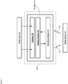
- FIG. 1 depicts a block diagram of a package in accordance with an illustrative embodiment of the present invention.
- Package 100 is an oral-contraceptive protective case that includes smart-packaging capability, which enables it to monitor the state of OCP blister card 102 and enable tracking of the drug regimen for the tablets it contains, initiate messages to the user and/or caregivers, and the like.
- Package 100 includes housing 104, receiver 106, detection module 108, and electronics module 110.
- Package 100 is dimensioned and arranged to accept a conventional "push-through-pack" blister card comprising a twenty-eight-day dosage of oral contraceptive tablets and locate the blister card such that it is operatively coupled with the detection module.
- FIGS. 2A-B depict schematic drawings of perspective and cross-sectional views, respectively, of blister card 102.
- Blister card 102 is a conventional blister card that includes forming film 202, lidding film 204, reservoirs 206, and tablets 210.
- Forming film 202 is a layer of thermoformed plastic in which cavities 208 are formed.
- Lidding film 204 is a thin sheet of aluminum foil. In some embodiments, lidding film 204 is a sheet of another electrically conductive material. In some embodiments, lidding film 204 includes a sheet of conductive material and a sheet of electrically insulating material, such as a paper sheet (with a printed calendar or instructions), polymer, etc. After tablets 210 are dispensed into cavities 208, lidding film 204 is joined with forming film 202 to seal the cavities, thereby forming reservoirs 206. Typically, a calendar that describes the drug regimen is printed on the card and/or otherwise provided as part of the blister card.
- the region of lidding film 204 located under each cavity defines a dispensing region 212, through which its respective tablet 210 is dispensed by pushing the tablet through the lidding foil.
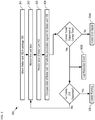
- FIG. 3 depicts operations of a method for monitoring a drug regimen in accordance with the illustrative embodiment.
- Method 300 begins with operation 301, wherein blister card 102 is located in package 100 .
- Method 300 is described with continuing reference to FIGS. 1 and 2A-B .
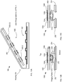
- FIG. 4 depicts a schematic drawing of a perspective view of package 100 including inserted blister card 102.
- housing 104 is an injection-molded plastic case having sufficient strength to protect blister card 102 from damage during normal handling and storage, such as might happen, for example, if blister card 102 were kept in a purse or a pocket without such protection.
- the location of blister card 102 within package 100 is determined by receiver 106 (i.e ., receiver 106 locates blister card 102).
- Receiver 106 is a rigid frame containing openings for exposing reservoirs 206 of blister card 102. To locate blister card 102 in housing 104, the blister card is positioned within a seat formed in the bottom of housing 104 (not shown) and receiver 106 is closed over the blister card to trap it in place.
- Receiver 106 is dimensioned and arranged to provide distributed pressure over the surface of the blister card to ensure that it is operatively coupled with detection module 108.
- blister card 102 includes printed information on its forming-film side (e.g ., instructions for the user, advertising, logos, etc .).
- those package components e.g ., receiver 106
- those package components e.g ., receiver 106
- overlay such printed information would be made of optically transparent material.
- receiver 106 comprises a different conventional latching system for locating a blister card in housing 104 such that it is operably coupled with detection module 108.
- FIG. 5 depicts an enlarged cross-sectional view of a portion of an alternative receiver 106.
- the cross-sectional view depicted in FIG. 5 is taken through region 406 of FIG. 4 .
- Receiver 106 includes a plurality of latches 502 and shoulder 504, which are formed as part of the outer wall of housing 104.
- Latch 502 is a deformable tab that can be depressed to enable blister card 102 to seat against shoulder 504.
- the tab is resilient such that once the blister card is located in its proper position against the shoulder, it springs outward to lock the blister card in this position.
- the desired position of blister card 102 is abutting the top surface of detection module 108, as discussed below.
- latches 502 and shoulder 504 are formed as part of the sidewalls of housing 104 in accordance with conventional injection molding techniques.
- receiver 106 there are myriad conventional ways to form receiver 106 and that the receiver designs depicted in FIGS. 4 and 5 are merely examples of receivers suitable for use with the present invention.
- Detection module 108 is a two-dimensional arrangement of sensors that substantially matches the arrangement of tablets 210 in blister card 102.
- detection module 108 includes a mechanically robust plate comprising a plurality of holes through which tablets 210 are dispensed.
- detection module 108 employs capacitive sensing technology to monitor the state of blister card 102. It will be clear to one skilled in the art, after reading this Specification, however, that many alternative sensing technologies can be employed in detection module 108 without departing from the scope of the present invention as determined by the following claims.
- Sensing technologies suitable for use in embodiments of the present invention include, without limitation, optical sensing, acoustic sensing, and tactile sensing, among others. Detection module 108 is described in more detail below.
- Electronics module 110 is an electronics package that is operatively coupled with detection module 108.
- Electronics module 110 comprises electronic circuitry suitable for interfacing with the sensors of the detection module, signal-conditioning electronics (e.g ., pre-amplifiers, comparators, etc .) for receiving the output signals of each sensor, output electronics for providing output signal 112, and the like.
- signal-conditioning electronics e.g ., pre-amplifiers, comparators, etc .
- output electronics for providing output signal 112, and the like.
- electronics module 110 includes, without limitation:
- electronics module 110 communicates with mobile device 114 wirelessly via output signal 112 and input signal 116 .
- Mobile device 114 is a cell phone that runs a software application (i.e ., a mobile app) that provides assistance to the patient and/or caregiver to achieve and maintain good adherence to the prescribed drug regimen.
- electronics module 110 communicates with a different device, such as a computer and/or base station. Further, in some embodiments, electronics module 110 is integrated with detection module 108 on the same substrate.
- electronics module 110 includes sleep-mode circuitry to facilitate long battery life between charges. In such embodiments, sensing is activated only when desired and the instrument is in sleep mode most of the time.
- sleep-mode circuitry suitable for use in embodiments of the present invention include, without limitation, low-power accelerometers, touch/proximity sensors, and the like.
- housing 100 is based on the particular arrangement of blister card 102, as well as the sensing technology used to monitor its state.
- the design details provided herein are merely exemplary and that myriad alternative designs are possible without departing from the scope of the present invention as determined by the following claims.
- detection module 108 and electronics module 110 are embedded into the bottom surface of housing 104 . It should be noted, however, that there are numerous ways to integrate detection module 108 and/or electronics module 110 into housing 104 without departing from the scope of the present invention as determined by the following claims.
- detection module 108 is embedded into the bottom of housing 104
- electronics module 110 is mounted on lid 402 .
- Interconnects (not shown) embedded in housing 104 run through hinge 404 to electrically couple the detection and electronics modules.
- housing 104 includes an extra compartment to house electronics module 110.
- detection module 108 and electronics module 110 are disposed in or on one or more printed circuit boards (PCBs) that are mounted in housing 104 (i.e ., a hybrid implementation).
- PCBs printed circuit boards
- electronics module 110 includes a touch display disposed on housing 104 to enable direct interaction with the user via displayed text, graphics, user input, and the like.
- electronics module 110 monitors the time and date via an onboard clock.
- mobile device 114 monitors the time and date.
- electronics module 110 requests time and date information from mobile device 114.
- the time and date is tracked in another conventional manner.
- the state of blister card 102 is monitored.
- One skilled in the art will recognize that the manner in which the state of blister card 102 is determined is based on the sensing technology employed. As mentioned briefly above, many sensing technologies can be used to sense the state of a blister card and examples of several sensing approaches are discussed in detail below.
- the state of blister card 102 is compared with the dosing regimen for the prescription it contains ( i.e ., tablets 210 ). In the illustrative embodiment, this comparison occurs periodically each day ( e.g ., every minute, hour, several hours, etc .) throughout the anticipated dosing period of 28 days.
- the prescribed dosing regimen is maintained in the mobile app running on mobile device 114, which provides regimen data to electronics module 110 via input signal 116.
- the dosing regimen is downloaded into a memory module included in electronics module 110.
- output signal 112 provides blister-card-state information to mobile device 114, which compares it to the dosing regimen.
- OCP apps typically begin with a setup stage when the app is first downloaded.
- the setup step normally requires a user to input several bits of personal information, such as:
- the routine use methodology includes providing reminder alerts to take the correct pill at the correct time (or within the proper time window). After taking a pill, the user then manually enters the time, date, and the pill taken into the app. The time-date-pill data is stored and is accessible to the user to analyze for adherence. The adherence data and trend can also be forwarded to one or more designated persons in the care circle of the user.
- Automated systems for tracking medication adherence via mobile apps are known; however, these are typically directed toward medication packaged in bottles. These conventional systems incorporate wireless connectivity and sensors to monitor and communicate adherence data in an accompanying mobile app and/or network servers. If a dose is missed, the system provides a reminder alert automatically, either by an indicator on the system itself or sent to the care circle of the user via an automated call or text message. The ability to automatically generate a reminder message represents an important step in supporting good adherence.
- Embodiments include apparatus and methods that enable further improvements to the conventional methodology described above, however. It should be noted that, although these improvements are particularly well suited for OCP compliance, they are also suited for use in many other medication compliance applications as well - particularly those that are significantly affected by the quality of adherence. Specifically, improvements to the prior art are enabled due to the fact that it is enabled:
- the present invention affords several significant advantages over automated tracking systems of the prior art are afforded. For example, it is enabled an ability to monitor the distance between blister card 102 and a mobile device. This provides monitoring capability that can determine whether the blister card and the mobile device are within the same general space (e.g ., a home). As a result, if, for example, the user were leaving her home without her pills, an alert could be sent to the user. The stridency of the reminder could be weighted in importance depending on whether the next dose were due shortly ( e.g ., in the next hour or the same day) or not until the following day. In some embodiments, information on an electronic calendar kept on the mobile device is accessed to determine the risk in leaving the pills behind, e.g ., does she have an overnight trip scheduled, etc.
- the ability to compare actual adherence information acquired by package 100 to OCP the regimen for blister card 102 enables embodiments of the present invention to provide a user with next recommended steps. This is particularly advantageous when adherence is interrupted, such as when a pill is missed and the user is unsure of how to best mitigate the risk of an unintended pregnancy,
- the adherence-status feedback can be stored in long-term memory at a monitoring site for use in long-term care treatment planning, to enable its use as evidence in legal proceedings, civil proceedings ( e.g ., paternity suits, etc .), and the like.
- the status of the blister card (e.g ., number of pills dispensed, which pills have been dispensed, etc .) is saved at case closure. Upon the next opening of the case, the status of the blister card is again examined and compared to the last saved state. This ensures that untimely change of a blister card is detected and the user is asked related questions through the mobile app. Further, the blister-pack state upon opening provides a baseline against which a state change can be measured. In some embodiments, detection of an unanticipated difference between the blister-pack states at closing and opening gives rise to an alarm, error flag, or transmission to the user and/or third party to alert one or both of the possibility of an error.
- method 300 continues with operation 305A, wherein an error signal is initiated by electronics module 110.
- Improper events that would initiate an error signal to the user or user's care circle include, without limitation:
- a reminder can be sent to the user to encourage her to take the proper pill.
- operation 304 reveals that the correct tablet 210 has been dispensed within its allotted dosing-time window, at operation 305B, the time at which the tablet was dispensed is logged into memory by electronics module 110.
- operation 306 a warning to the user or user's care circle is initiated to alert them that blister card 102 is now empty. In some embodiments, this warning is generated when the number of tablets in the blister card 102 has dropped to a threshold level so as to initiate a refill reminder to the user or user's care circle, or generate a refill request directly to the pharmacy.
- method 300 continues with the repetition of operations 302 through 306.
- the mobile app may incorporate additional features to help the user to better manage her health. For example, at operation 305B, the user may be provided a reward through the mobile and/or an opportunity to input notes into the mobile app, e.g ., recording experiencing side effects, having intercourse in the last 24 hours, etc .
- the mobile app may provide the user with counseling and education information. Since the point of the cycle for the user is known, the mobile app may provide contextual health and wellness information to the user.
- method 300 is merely one non-limiting, exemplary method for improving a drug regimen and that myriad alternative methods can be employed without departing from the scope of the present invention as determined by the following claims.
- detection module 108 includes a plurality of capacitive sensors, as described herein,
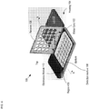
- FIGS. 6A-B depict schematic drawings of top and cross-sectional views, respectively, of a capacitive-sensing-based detection module in accordance with the illustrative embodiment of the present invention.
- Detection module 108 comprises substrate 602, holes 604, and sensors 606-1 through 606-28 (referred to, collectively, as sensors 606).
- Substrate 602 is a conventional PCB substrate. Substrate 602 is sized to fit into housing 104 such that it forms the bottom of package 100 . Typically substrate 602 is held in housing 104 via a receiver that is analogous to receiver 106 described above. In some embodiments, substrate 602 is another substrate, such as a semiconductor wafer suitable for planar processing, and the like. In some embodiments, instead of a rigid substrate ( e.g ., substrate 602 ), detection module 108 comprises a substrate that is flexible and optionally visually transparent, as discussed below and with respect to FIGS. 13A-B .
- Holes 604 extend through substrate 602 to allow for the passage of each of tablets 210 through detection module 108 when they are dispensed from the blister card.
- Each of sensors 606 includes an electrode 608 and its respective dispensing region 212 of lidding film 204.
- Electrode 608 is a planar, circular metal electrode that completely surrounds hole 604. Electrode 608 is formed within the body of substrate 602 such that, when blister card 102 is in contact with detection module 108, the electrode and lidding film 204 form a capacitive sensor 606, whose capacitance is based on the state of the lidding film in its respective dispensing region 212, as depicted in FIG. 6B .
- sensors 606 (as well as other sensors described herein) are formed directly on a surface of the bottom of housing 104, thereby obviating substrate 602.
- sensors 606 is electrically connected to sensing circuitry in electronics module 110 via electrical traces (not shown for clarity). As a result, each sensor can be monitored individually to enable specificity of the dispensing of each tablet 210 of blister card 102. In some embodiments, sensors 606 are electrically connected and interrogated using a row/column addressing scheme.
- OCP represents one of many application wherein it is critical to be able to identify when tablet has been dispensed during a dispensing event.
- One skilled in the art will recognize, however, after reading this Specification, that not all medication requires the ability to uniquely identify the identity of a tablet that has been dispensed and, as a result, the sensing approach used to detect tablet dispensing can be greatly simplified, For example, in some cases, all of the tablets of a blister card are substantially identical. In some embodiments of the present invention, therefore, all of sensors 606 are electrically connected in parallel or serially and specificity for which tablet 210 is dispensed is not enabled.
- a single sensor is used to detect dispensing events, such as an accelerometer operatively coupled with the blister card, a single capacitive sensor that spans all the tablet sites such that each dispensing event is indicated by a change in the capacitance of this solitary capacitor.
- row/column sensing is simplified to row or column sensing wherein, for example, one electrode of a capacitive sensor is common to an entire row or column of tablet locations, while the other electrode is divided into site-specific individual electrodes.
- exhaustion of a blister card (which denotes a refill is due) can be detected in numerous ways, such as simply tracking the dispensing events and comparing their count to the total count of the tablets on the blister card as provided or monitoring of the total magnitude of the sensor output signal change with dispensing events and comparing the result with a reference magnitude change determined, for example, by prior calibration operation.
- each sensor 606 the conductive material (i.e ., lidding film 204 ) of its dispensing region 212 forms fringing fields with its electrode 608. These fringing fields impact the capacitance of the capacitive sensor giving it a first value when the dispensing region is intact.
- the breakage of dispensing region 212 changes the physical configuration between the lidding film material and electrode 608, which affects the fringing fields and, therefore, the capacitance of sensor 606. It should be noted that the capacitance of sensor 606 changes whether or not the material of dispensing region 212 breaks away entirely or pieces of it remain hanging in hole 604 thereafter.
- lidding film 204 is electrically grounded, while each electrode 608 is connected to a high-impedance sense circuit.
- lidding film 204 is left electrically "floating;” however, grounding the lidding film is preferable because it provides improved sense-signal stability and noise immunity.
- sensor 606 can be sensitive to external noise and interference, such as stray or parasitic capacitances, electromagnetic interference (EMI), and the like.
- EMI electromagnetic interference
- electrode 608 in order to mitigate the effects of noise and interference, is segmented into a pair of half-rings. In some embodiments, electrode 608 is segmented into more than two circumferential sections. Using such electrode configurations, capacitive sensing is implemented by monitoring the change in the capacitance between the electrode segments, which is still affected by fringing fields between the electrode segments and the aluminum foil over the hole. Unfortunately, while segmenting electrode 608 provides some measure of noise immunity, noise and interferences can still be a problem.
- FIG. 7 depicts a cross-sectional view of an alternative capacitive sensor having improved noise immunity in accordance with the present invention.
- Sensor 700 is suitable for use in detection module 108 and comprises substrate 602, electrode 608, and electrode 702.
- Sensor 700 has significantly improved noise immunity as compared to sensor 606.
- Electrode 702 is analogous to electrode 608; however, electrode 702 is formed within substrate 602 such that it is parallel with electrode 608 and located distal to lidding film 204 when blister card 102 is located in package 100. Electrodes 608 and 702 collectively define a parallel-plate capacitor within substrate 602,
- Sensor 700 operates in accordance with projected capacitive sensing techniques, such as those described in Microchip Application Note TB3064 entitled, “mTouchTM Projected Capacitive Touch Screen Sensing Theory of Operation,” published January 5, 2010 .
- FIG. 8 depicts a schematic drawing of the electrical connectivity of sensor 700.
- electrodes 608 and 702 collectively define capacitor C1, whose value is determined by the mutual capacitance between the electrodes.
- Electrode 608 and lidding film 204 collectively define capacitor C2, whose capacitance is determined by the fringing fields between electrode 608 and the lidding film. These fringing fields are based on the state of detection region 212.
- Capacitance C3 is the touch capacitance between electrode 608 and the finger of the user, which develops only while the user is pressing on forming film 202 to push tablet 210 through lidding film 204 and after the lidding film has broken in dispensing region 212 , as discussed below.
- Electrode 608 is also characterized by substantially fixed electrode capacitance C4.
- electrode 702 is characterized by its own substantially fixed electrode capacitance C5.
- electrode 608 is driven as a transmitter and receives drive signal 802 from electronics module 110.
- Electrode 702 operates as a receiver and provides output signal 804 to sensing circuitry in electronics module 110, where the output signal is based on mutual capacitance C1.
- detection region 212 Prior to the dispensing of tablet 210, detection region 212 is whole and fringing capacitance C2 and mutual capacitance C1 are substantially unchanging since the physical configuration of their respective elements remains fixed.
- the value of capacitor C3 is substantially zero, since the intact lidding film 204 in the detection region 212 shields electrode 608 from stray capacitance and electrical noise from regions opposite lidding film 204 from the electrodes.
- the intact lidding film 204 in the detection region 212 acts as an "electrical shield" for electrode 608.
- an "electrical shield” is defined as an element that mitigates the effects of stray capacitance, electrical noise, and electrical interference on an electrical parameter measured at another element.
- high-impedance electrode 702 remains unshielded for noise and interference received from directions other than from the top of housing 104.
- FIG. 9 depicts a cross-sectional view of another alternative capacitive sensor having improved noise immunity in accordance with the present invention.
- Sensor 900 is suitable for use in detection module 108 and comprises substrate 602, electrodes 608 and 702, and electrode 902. Sensor 900 has significantly improved noise immunity as compared to sensors 606 and 700.
- Electrode 902 is analogous to electrode 702; however, electrode 902 is formed within substrate 602 such that it is parallel with electrodes 608 and electrode 702 but located such that electrode 702 is between electrodes 608 and 902. Electrodes 608 and 702 collectively define a first parallel-plate capacitor within substrate 602 and electrodes 702 and 902 collectively define a second parallel-plate capacitor with the substrate.
- FIG. 10 depicts a schematic drawing of the electrical connectivity of sensor 900.
- electrode 702 operates as a sense electrode that is sandwiched between driving electrodes 608 and 902, which shield the sense electrode from noise and interference emanating from above blister card 102 and below housing 104.
- Electrodes 702 and 902 collectively define capacitor C6, whose value is determined by the mutual capacitance between these electrodes.
- Electrode 902 and lidding film 204 collectively define capacitor C7, whose capacitance is determined by the physical configuration between electrode 902 and lidding film 204. Like capacitor C2, the value of this capacitance is based on the state of detection region 212 .
- Electrode 902 is also characterized by capacitor C8, which is analogous to capacitor C3, described above.
- Electrode 902 is also characterized by substantially fixed electrode capacitance C9.
- sensor 900 The operation of sensor 900 is analogous to that of sensor 700; however, the fringing-field capacitances of sensor 900 additionally include C7 and C8 , whose capacitances are determined by the fringing fields between electrode 902 and lidding film 204, as well as touch capacitances C3 and C8.
- the values of fringing-field capacitances C7 and C8 are based on the state of detection region 212, although the value of C7 can also be influenced by the touch of the user on the back of housing 104,
- additional shielding is provided for sense electrodes 702 by adding shielding lines that surround each sense electrode in its plane within substrate 602.
- FIG. 11 depicts a plan view of a detection module having improved noise immunity by virtue of shield lines formed around each of its sense electrodes.
- Detection module 1100 is analogous to detection module 108; however, detection module 1100 includes a plurality of sensors 900 and shield lines 1102.
- FIG. 11 depicts a section of detection module 1100 as taken through the plane of electrodes 702.
- Shield lines 1102 are electrically conductive traces formed such that they nearly completely encircle sense electrodes 702 in the plane of the electrodes. Shield lines 1102 are electrically grounded as depicted in the figure.
- each of sense electrodes 702 is virtually completely shielded from interference from all external noise and EMI sources. It should be noted that shield lines 1102 can also be incorporated into sensors 606 and 700, described above.
- electrodes 702 are optionally electrically connected together in each column of the 7x4 array of sensors 900. Even though they are electrically connected as shown, each sensor 900 can be individually detected by employing a row-column addressing scheme in which each row of drive electrodes 608 and 902 are driven in either a time-division-multiplexed fashion, or with different drive frequencies. In some embodiments, each of electrodes 702 is individually electrically connected with electronics module 110.
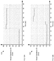
- FIGS. 12A-B depict measurement results for two individual sensors 900 in response to the sequential dispensing of two tablets from blister card 102.
- Plots 1200 and 1202 show the capacitance of mutual capacitor C6 versus time for two sensors 900 in detection module 1100.
- tablet 210 is dispensed at a time of 34 seconds.
- plot 1202 tablet 210 is dispensed at a time of 45 seconds.
- the corresponding mutual capacitance changes significantly, enabling detection of each dispensing event.
- the presence or absence of a tablet 210 in each reservoir 206 can also be determined by the absolute magnitude of these sense capacitances, using a previously calibrated threshold value to indicate presence or absence of a tablet in each reservoir 206.
- predictive models/algorithms based on modeling and experimentation are used to relate specific sensor output signatures with dispensing events.
- the model is then used for tablet identification during a dispensing event based on the sensor output.
- the output signatures of a motion sensor in a detection module would enable the location at which a dispensing event occurred to be determined by utilizing a respective predictive model/algorithm.
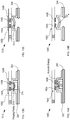
- FIG. 13A depicts a schematic drawing of a cross-sectional view of package 100 having an alternative capacitive-sensing-based detection module.
- Package 100 is depicted in its open state and with blister card 102 located in the package by receiver 106 (not shown for clarity).
- the package cross-section depicted in FIG. 13A is taken through a plane along line b-b depicted in FIG. 4 .
- Detection module 1300 includes sensor substrate 602 and sensors 1302-1 through 1302-28 (referred to, collectively, as sensors 1302), which are arranged on the substrate in an arrangement that matches that of tablets 210 on blister card 102.
- Detection module 1300 is analogous to detection module 108 described above; however, detection module 1300 is located in lid 402 by a receiver that is analogous to receiver 106 described above (not shown for clarity). The closure of lid 402 brings detection module 1300 into close proximity with blister card 102, thereby operatively coupling each of sensors 1302 with its respective tablet 210.
- FIGS, 13B-C depict cross-sectional views a portion of detection module 1300 before and after dispensing of a tablet, respectively, in accordance with the present invention.
- Each of sensors 1302 includes electrodes 1304 and 1306 and shield 1308.
- Electrodes 1304 and 1306 are electrically conductive electrodes disposed on a first surface of substrate 602.
- Shield 1308 is an electrically conductive electrode disposed on a second surface of substrate 602. Shield 1308 is grounded such that it is operative for shielding electrodes 1304 and 1306 from electrical noise and interference emanating from the top side of detection module 1300. Lidding film 204 is also typically grounded, thereby enabling it to act as a shield from the bottom side for electrodes 1304 and 1306.
- electrodes 1304 and 1306 are capacitively coupled with tablet 210 via fringing fields 1310. As a result, the capacitance between electrodes 1304 and 1306 is based on these fringing fields.
- fringing fields 1310 are coupled with only the remnants of reservoir 206 (i.e ., deformed forming film 202 ), which gives rise to a difference in the capacitance between electrodes 1304 and 1306 from that of a filled reservoir because of the different manner in which fringing fields 1310 couple with the empty reservoir.
- detection module 1300 interrogates blister card 102 each time lid 402 is closed, The output signal from the detection module is then compared to the most recent previous blister-pack state to determine whether a tablet has been dispensed and, if so, which tablet.
- the presence or absence of a tablet 210 in each reservoir 206 is determined by a change in the absolute magnitude of sense capacitances between lid closures, using a previously calibrated threshold value to indicate presence or absence of a tablet in each reservoir 206 .
- FIGS. 13D-E depict cross-sectional views of a portion of yet another alternative capacitive-sensing-based detection module, before and after dispensing of a tablet, respectively, in accordance with the present invention
- Detection module 1312 is analogous to detection module 1300 described above; however, detection module 1312 is a flexible detection module that is dimensioned and arranged to be placed in contact with blister card 102 during operation.
- Detection module 1312 includes substrate 1314 and the plurality of capacitive sensors 1302, as described above.
- Substrate 1314 is a flexible substrate comprising polyimide.
- substrate 1314 is formed of another material suitable for flexible electronics, such as a polymer, such as poly(methylacrylate) (PMMA), polyimide, polyurethane, polyester, polyether ether ketone (PEEK), and the like.
- PMMA poly(methylacrylate)
- PEEK polyether ether ketone
- substrate 1314 is sufficiently flexible to enable a force applied to it to deform forming film 202 and push tablet 210 through lidding film 204.
- electrodes 1304 and 1306 are capacitively coupled with tablet 210 via fringing fields 1310. As discussed above, the capacitance between electrodes 1304 and 1306 is based on fringing fields 1310 such that the capacitance of each sensor 1302 is based on the presence of its respective tablet 210.
- the use of a flexible substrate also enables integration of detection module 1312 in or on forming film 202.
- detection module 1312 is formed such that it includes an interior volume for receiving blister card 102 (i.e ., detection module has the form analogous to a flexible pouch).
- the interior volume is dimensioned and arranged such that, when blister card 102 is located in the pouch, the pouch holds the blister card in intimate contact on the top (forming-film side) and bottom surfaces (lidding-film side).
- the top and bottom surfaces of the pouch incorporate holes to enable access to reservoirs 206 and dispensing regions 212.
- the detection module may include a substrate that is sufficiently flexible to partially or fully cover the topside holes. It should be noted that such embodiments can be implemented using more than one of the different sensing approaches described herein. These embodiments are particularly well suited for use with capacitive sensing and tactile sensing techniques.
- FIGS. 14A-B depict cross-sectional views of a portion an alternative acoustic-sensing-based detection module, before and after dispensing of a tablet, respectively, in accordance with the present invention.
- Detection module 1400 is analogous to detection module 108 described above; however, detection module 1400 includes substrate 602 and a plurality of acoustic sensors 1402, each of which is operative for detecting the presence of a tablet in a blister-card reservoir when the detection module is operatively coupled with a blister card from its forming-film side.
- Each of acoustic sensors 1402 comprises transmitter 1404 and acoustic detector 1406.
- Transmitter 1404 is a piezoelectric transducer operative as a conventional acoustic transmitter. Transmitter 1404 is arranged to direct acoustic energy (e.g ., ultrasonic waves, etc .) toward tablet 210 when detection module 1400 is aligned with blister card 102.
- acoustic energy e.g ., ultrasonic waves, etc .
- Acoustic detector 1406 is a piezoelectric transducer operative as a conventional acoustic receiver. Acoustic detector 1406 is arranged to receive acoustic energy from the direction of tablet 210 when detection module 1400 is aligned with blister card 102.
- detection module 1400 is mounted on the inside surface of lid 402 of housing 104. Sensors 1402 are arranged on substrate 602 such that, when lid 402 is closed, the sensors are brought into contact with reservoirs 206 of blister card 102 to operatively couple each sensor with a different reservoir. In some embodiments, sensors 1402 and reservoirs 206 are separated by a small air gap when lid 402 is closed. In some embodiments, detection module 1400 is located within housing 104 via a receiver, as discussed above.
- each of sensors 1402 provides an electrical signal whose magnitude is indicative of whether its respective reservoir contains a tablet.
- electronics module 110 can determine that a tablet-dispensing event has occurred, as well as identify which tablet has been dispensed.
- the presence or absence of a tablet 210 in each reservoir 206 determined based on the absolute magnitude of acoustic signatures, using previously calibrated threshold values to indicate presence or absence of a tablet in each reservoir 206 .
- detection module 1400 comprises a flexible substrate that is analogous to substrate 1312 described above.
- sensors 1402 are formed in such substrate using flexible piezoelectric films (e.g ., polyvinylidene fluoride or polyvinylidene difluoride, also known as PVDF, etc. ) in accordance with conventional flexible-electronics fabrication technology.
- flexible piezoelectric films e.g ., polyvinylidene fluoride or polyvinylidene difluoride, also known as PVDF, etc.
- the use of a flexible substrate in detection module 1400 enables a force applied to the detection module to deform forming film 202 and push tablet 210 through lidding film 204. It also enables integration of detection module 1400 in or on forming film 202 .
- a flexible substrate enables the use of the piezoelectric materials of sensors 1402 to harvest mechanical energy (e.g ., such as that generated while a tablet is being dispensed) and convert it into electrical energy usable for powering detection module 1400.
- detection module 1400 can be dimensioned and arranged for operation from the lidding film side of blister card 102 without departing from the scope of the present invention as determined by the following claims.
- transmitter-free acoustic sensing is achieved by disposing three or more microphones on blister card 102.
- FIG. 15 depicts a schematic drawing of a perspective view of a blister card comprising a plurality of microphones in accordance with another acoustic-sensing-based embodiment of the present invention.
- Blister card 1500 is analogous to blister card 102; however, bister card 1500 includes six microphones 1502, which are disposed on forming film 202 and distributed across its area.
- each microphone detects the sound of a tablet being dispensed.
- Signal processing capability included in electronics module 110 and/or mobile device 114 processes the outputs of the microphones to triangulate the sound and identify the specific tablet location at which it originates.
- detection module 1500 comprises a flexible substrate, which is placed in contact with blister card 102 within housing 104.
- detection module 1500 comprises a conventional PCB substrate that is mounted on the inside surface of lid 402 of housing 104.
- microphones 1502 are disposed on a PCB substrate having holes that enable force to be applied to reservoirs 206.
- the PCB substrate would be in the shape of a frame, running along one or more of the inside sidewalls of the housing 104 adjacent to the blister card 102.
- detection module 1500 is mounted therein. In some embodiments, detection module 1500 is located therein via a receiver.
- FIGS. 16A-B depict cross-sectional views of a portion of a tactile-sensing-based detection module, before and after dispensing of a tablet, respectively, in accordance with the present invention.
- Detection module 1600 is analogous to detection module 108 described above; however, detection module 1600 includes substrate 602 and a plurality of tactile sensors 1602, each of which is operative for detecting the presence of a tablet in a blister-card reservoir when detection module 1600 is operatively coupled with blister card 102 from its forming-film side.
- Sensors 1602 are disposed on substrate 602 in an arrangement that substantially matches the arrangement of tablets in blister card 102.
- detection module 1600 is mounted on the inside surface of the lid 402 of housing 104. In some embodiments, detection module 1600 is located within housing 104 via a receiver, as discussed above.
- each of tactile sensors 1602 includes electrodes 1604 and 1606 and optional shield 1308.
- Each of tactile sensors 1602 is a parallel plate capacitor comprising conventional planar electrodes 1604 and 1606 and projection 1608, which is a projection of soft dielectric material (e.g ., PMMA, etc .) disposed between and around electrodes 1604 and 1606.
- the capacitance of sensor 1602 is based on the spacing between its electrodes.
- sensors 1602 are put into contact with reservoirs 206.
- a pressure/force is generated between sensor 1602 and the reservoir, which is sufficient to depress the forming film 202 of the reservoir 206 but not large enough to break the lidding film 204 in the dispensing region 212.
- This force causes compression of the material between electrodes 1604 and 1606, giving rise to a relatively large capacitance for sensor 1602.
- a sensor is place in contact with a reservoir that does not contain a tablet, however, little, if any, force is generated between the sensor and the reservoir. As a result, the amount of compression of the material between electrodes 1604 and 1606 is minimal, giving rise to a relatively lower capacitance for the sensor.
- electronics module 110 reads the capacitance of each sensor 1602 and determines which tablets have been dispensed from blister card 102.
- the region between electrodes 1604 and 1606 is occupied by a piezoelectric material, which provides an electrical output based on the force applied to tactile sensor 1602.
- a piezoelectric material which provides an electrical output based on the force applied to tactile sensor 1602.
- substrate 602 is replaced with a flexible substrate, such as substrate 1314.
- sensors 1602 are formed in such a substrate using flexible electronics fabrication technology.
- detection module 1600 is sufficiently flexible to enable a force applied to it to deform forming film 202 to push tablet 210 through lidding film 204.
- Such embodiments enable integration of detection module 1600 in or on the forming film of the blister card.
- the detection module 1600 is operatively coupled with the blister card from its lidding-film side.
- Sensors 1602 are arranged between dispensing regions 212, such that they are operative for sensing forces imparted to bister card 104 during each dispensing operation.
- sensors 1602 can be realized based on any principle that generates a detectable signal, electrical or other, as a result of a tactile stimulus.
- a broader interpretation of tactile sensing would for example include measurement of deformations of the blister card 102 or surfaces of the housing 104 by utilizing strain sensors on/in flexible substrates directly printed on such surfaces.
- FIGS. 17A-B depict cross-sectional views of a portion of an optical-sensing-based detection module, before and after dispensing of a tablet, respectively, in accordance with the present invention.
- Detection module 1700 is analogous to detection module 108 described above; however, detection module 1700 includes substrate 602 and a plurality of optical sensors 1702, each of which is operative for detecting the presence of a tablet in a blister-card reservoir when the detection module is operatively coupled with a blister card from its forming-film side. In the depicted example, detection module 1700 is located on the inside surface of lid 402.
- Each of sensors 1702 comprises photodetector 1704, which is operative for detecting light 1706.
- the plurality of photodetectors are disposed on substrate 602 in an arrangement that substantially matches that of tablets 210 of blister card 102.
- light 1706 is ambient light that originates outside housing 104.
- light 1706 is provided by a light source included within package 100, typically mounted underneath detection module 108.
- Light sources in accordance with the present invention include, without limitation, diffuse light sources, arrays of light emitters (e.g ., LEDs, lasers, etc .) aligned with photodetectors 1704, etc.
- opaque lidding film 204 is fractured, thereby enabling light to pass through detection region 212 of that tablet site to reach photodetector 1704.
- detection of light by a photodetector signals that a tablet has been dispensed from its respective sensor location.
- the state of blister card 102 is interrogated after each time lid 402 is closed.
- detection module 1700 is disposed on the top side (i.e ., forming-film side) of blister card 102 in the depicted example, it will be clear to one skilled in the art, after reading this Specification, how to make and use alternative embodiments wherein detection module 1700 is disposed on the bottom side (i.e ., lidding-film side) of blister card 102 such that light signal 1706 passes through the blister card from the top side to the bottom side. In some of these embodiments, the state of blister card 102 is determined at the opening of lid 402.
- the substrate of detection module 1700 is formed of a transparent, flexible substrate comprising a substantially transparent polymer, such as PMMA, polyimide, polyurethane, polyester, PEEK, and the like.
- detection module 1700 can be located in contact with blister card 102.
- the substrate is made of a material suitable for the formation of flexible electronics and is sufficiently flexible to enable a force applied to it to deform forming film 202 to push tablet 210 through lidding film 204.
- the use of a flexible substrate also enables integration of detection module 1700 in or on forming film 202.
- detection module 1700 includes planar-lightwave circuits (PLCs) whose surface waveguides convey light generated from a source remote to sensors 1702 to each sensor and collect light transmitted through the sensor region and convey it to a remote detector.
- PLCs planar-lightwave circuits
- the PLCs are substantially parallel with blister card 102 and light is coupled from the PLCs into and out of the sensor region via vertical grating couplers.
- FIGS. 18A-B depict cross-sectional views of a portion of an optical-sensing-based detection module, before and after dispensing of a tablet, respectively, in accordance with the present invention.
- Detection module 1800 is analogous to detection module 1700 described above; however, detection module 1800 is located on the inside bottom surface of housing 104 and operates in reflection mode.
- Detection module 1800 includes a plurality of sensors 1802, which is arranged to match the arrangement of tablets in blister card 104.
- Each sensor 1802 includes a photodiode 1704, which is dimensioned and arranged to detect light reflected from lidding film 204 only when its respective dispensing region 212 is intact. In the depicted example, sensors 1802 detect ambient light. In some embodiments, each of sensors 1802 also includes a light source for illuminating dispensing region 212. In some embodiments, a single light source is included in detection module 1800 to illuminate the entire lidding film with diffused light.
- thermal sensing can also be used to detect a tablet dispensing event in accordance with the present invention.
- detection of the breaking of the lidding film in the dispensing region can be detected.
- a first resistor disposed on lidding film 204 at one side of dispensing region 212 is driven to generate heat into the lidding film.
- the heat is then detected by a temperature sensor disposed on the lidding film 204 on the other side of the dispensing region, When the temperature of the heater is increased by an incremental amount, if the lidding film is intact in the dispensing region, a temperature rise is detected by the temperature sensor.
- heat conduction through dispensing region 212 is impeded and the detected temperature rise at the temperature sensor is significantly smaller.
- FIG. 19 depicts a schematic drawing of a perspective view of a multi-blister-card package in accordance with an alternative embodiment .
- Package 1900 is a metapackage that is operative for monitoring the state of multiple blister cards 102, where each blister card can have a different prescription or multiple copies of the same prescription.
- Package 1900 includes housing 1902, electronics module 110, receivers 1904-1 through 1904-N and detection modules 1906-1 through 1906-N.
- Package 1900 is dimensioned and arranged to receive and locate blister cards 102-1 through 102-N.
- Housing 1902 is analogous to housing 104; however, housing 1902 is dimensioned and arranged to contain multiple receivers, detection modules, and blister cards.
- Each of receivers 1904-1 through 1904-N (referred to, collectively, as receivers 1904) is analogous to receiver 106; however, each receiver 1904 includes a hinge that enables it to be rotated out to expose a different blister card.
- Each of detection modules 1906-1 through 1906-N (referred to, collectively, as detection modules 1906) is analogous to detection module 108; however, each detection module 1906 is dimensioned and arranged to monitor the status of a different blister card. In some embodiments, detection modules 108 employ multiple sensor technologies.
- Eacetection modules 1906 is electrically coupled with electronics module 110 as described above, which enables operation of package 408 as described above and with respect to package 100 .
Landscapes
- Health & Medical Sciences (AREA)
- Engineering & Computer Science (AREA)
- General Health & Medical Sciences (AREA)
- Public Health (AREA)
- Life Sciences & Earth Sciences (AREA)
- Animal Behavior & Ethology (AREA)
- Veterinary Medicine (AREA)
- Medical Informatics (AREA)
- Bioinformatics & Cheminformatics (AREA)
- Pharmacology & Pharmacy (AREA)
- Business, Economics & Management (AREA)
- Emergency Management (AREA)
- Physics & Mathematics (AREA)
- General Physics & Mathematics (AREA)
- Chemical & Material Sciences (AREA)
- Medicinal Chemistry (AREA)
- Epidemiology (AREA)
- Primary Health Care (AREA)
- Medical Preparation Storing Or Oral Administration Devices (AREA)
- Medical Treatment And Welfare Office Work (AREA)
- Investigating Or Analyzing Materials By The Use Of Ultrasonic Waves (AREA)
- Investigating Materials By The Use Of Optical Means Adapted For Particular Applications (AREA)
- Investigating Or Analyzing Materials By The Use Of Electric Means (AREA)
Applications Claiming Priority (3)
| Application Number | Priority Date | Filing Date | Title |
|---|---|---|---|
| US201662320234P | 2016-04-08 | 2016-04-08 | |
| US15/223,779 US10083594B2 (en) | 2016-04-08 | 2016-07-29 | Apparatus and method for improved drug regimen compliance |
| PCT/US2017/025302 WO2017176571A1 (en) | 2016-04-08 | 2017-03-31 | Apparatus and method for improved drug regimen compliance |
Publications (2)
| Publication Number | Publication Date |
|---|---|
| EP3439613A1 EP3439613A1 (en) | 2019-02-13 |
| EP3439613B1 true EP3439613B1 (en) | 2020-12-23 |
Family
ID=59998833
Family Applications (1)
| Application Number | Title | Priority Date | Filing Date |
|---|---|---|---|
| EP17719957.7A Active EP3439613B1 (en) | 2016-04-08 | 2017-03-31 | Apparatus and method for improved drug regimen compliance |
Country Status (6)
| Country | Link |
|---|---|
| US (4) | US10083594B2 (ja) |
| EP (1) | EP3439613B1 (ja) |
| JP (5) | JP7132126B2 (ja) |
| KR (1) | KR102385855B1 (ja) |
| CN (2) | CN109195569B (ja) |
| WO (1) | WO2017176571A1 (ja) |
Families Citing this family (26)
| Publication number | Priority date | Publication date | Assignee | Title |
|---|---|---|---|---|
| US10952927B2 (en) | 2014-10-10 | 2021-03-23 | QuantaEd, LLC | Apparatus for monitoring the content of a container and method therefor |
| US10650661B2 (en) | 2016-04-08 | 2020-05-12 | QuantaEd, LLC | Apparatus and method for improved drug dosing-regimen compliance |
| US20190185237A1 (en) * | 2016-09-01 | 2019-06-20 | Intel Corporation | Methods, systems, apparatus and articles of manufacture to monitor a product package |
| US10265246B2 (en) * | 2016-10-17 | 2019-04-23 | Capsule Technologies, Inc. | Smart blister pack with skin presence trigger |
| CN110430855B (zh) * | 2017-02-22 | 2023-01-10 | 匡特艾德有限公司 | 用于改进方案依从性的模块化药箱 |
| US10925810B2 (en) | 2017-04-10 | 2021-02-23 | Emme, Inc. | Method and system for improving and assisting in medication compliance |
| GB201711262D0 (en) * | 2017-07-13 | 2017-08-30 | Astrazeneca Ab | Medicament dispensing system and dispensing method |
| USD850097S1 (en) * | 2017-08-15 | 2019-06-04 | QuantaEd, LLC | Pill dispenser |
| US10634633B2 (en) | 2017-10-10 | 2020-04-28 | QuantaEd, LLC | Smart packaging for improved medication regimen compliance |
| EP3501475B1 (en) * | 2017-12-22 | 2024-06-19 | Popit Oy | Pill removal detection device |
| US11578999B2 (en) * | 2018-05-21 | 2023-02-14 | Counted, Llc | Usage tracking system |
| WO2020106330A1 (en) * | 2018-07-18 | 2020-05-28 | Pillsy, Inc. | Smart drug delivery and monitoring device, kit, and method of use for pill compounds |
| US10463574B1 (en) * | 2018-11-19 | 2019-11-05 | At&T Intellectual Property I, L.P. | Medication adherence monitoring |
| KR20210154810A (ko) * | 2019-03-20 | 2021-12-21 | 디지털 메디컬 테크놀로지스, 엘엘씨 (디/비/에이 어드히어테크) | 약물 관리를 위한 스마트 컨테이너, 센서 및 방법 |
| US10786428B1 (en) | 2019-04-02 | 2020-09-29 | Automated Assembly Corporation | Method of making a blister package lid |
| US20200383871A1 (en) * | 2019-06-07 | 2020-12-10 | QuantaEd, LLC | Reconfigurable Smart Package |
| USD977820S1 (en) * | 2019-06-13 | 2023-02-14 | QuantaEd, LLC | Case for holding a blister pack |
| US11685580B2 (en) | 2019-08-07 | 2023-06-27 | International Business Machines Corporation | Medication counterfeit detection |
| US11766384B2 (en) * | 2019-12-02 | 2023-09-26 | Aam Care, Inc. | Object-detecting container apparatus |
| JP7051059B2 (ja) * | 2019-12-18 | 2022-04-11 | 株式会社ネクイノ | 低用量ピル服用者への月経関連情報報知システム |
| BR202020003089U2 (pt) * | 2020-02-13 | 2021-08-24 | Smartpills Serviços De Informação Ltda | Dispositivo porta-blíster conectado a um servidor externo |
| US11357700B2 (en) * | 2020-03-04 | 2022-06-14 | 9155-0020 Quebec Inc. | Wireless medication blister pack system and blister pack attachment |
| CA3084744A1 (en) * | 2020-06-24 | 2021-12-24 | Intelligent Devices Sezc Inc. | Compliance kit and system |
| KR102478691B1 (ko) * | 2020-06-30 | 2022-12-19 | (주)콜러디 | 블리스터용 내용물 수용 기구, 이를 포함하는 복약 관리 시스템 및 내용물의 토출 여부를 판정하는 방법 |
| US20230355472A1 (en) * | 2022-05-09 | 2023-11-09 | Darien Okinza Nurse | Medication magazines and intelligent medication management systems |
| WO2023247572A1 (en) | 2022-06-20 | 2023-12-28 | Hovione Scientia Ltd | A method and device for determining thickness and solid fraction of a pharmaceutical tablet using non-invasive process electrical tomography |
Family Cites Families (55)
| Publication number | Priority date | Publication date | Assignee | Title |
|---|---|---|---|---|
| US4616316A (en) | 1982-07-01 | 1986-10-07 | The United States Of America As Represented By The Administrator Of Veterans Affairs | Medication compliance monitoring device having conductive traces upon a frangible backing of a medication compartment |
| US4617557A (en) | 1984-11-08 | 1986-10-14 | National Patent Development Corporation | Medication compliance aid for unit dose packaging |
| GB8718606D0 (en) * | 1987-08-06 | 1987-09-09 | Hiltcroft Packaging Systems Lt | Monitoring apparatus |
| JPH02257960A (ja) * | 1989-03-31 | 1990-10-18 | Nisshin Flour Milling Co Ltd | 薬の服用時間警報装置 |
| US5099463A (en) * | 1991-05-02 | 1992-03-24 | Lloyd Harry A | Portable electronic medication dosage instruction and alarm device |
| US5313439A (en) | 1992-07-17 | 1994-05-17 | Dan Albeck | Timer device for medications |
| US5412372A (en) | 1992-09-21 | 1995-05-02 | Medical Microsystems, Inc. | Article dispenser for monitoring dispensing times |
| US8092224B2 (en) | 1995-11-22 | 2012-01-10 | James A. Jorasch | Systems and methods for improved health care compliance |
| US5852590A (en) | 1996-12-20 | 1998-12-22 | De La Huerga; Carlos | Interactive label for medication containers and dispensers |
| JP2000048694A (ja) * | 1998-07-27 | 2000-02-18 | Omron Corp | 静電容量形近接センサ |
| US6411567B1 (en) | 2000-07-07 | 2002-06-25 | Mark A. Niemiec | Drug delivery management system |
| JP4590161B2 (ja) | 2001-05-21 | 2010-12-01 | スコット・ラボラトリーズ・インコーポレイテッド | 医療容器のためのrf−idラベル |
| JP4228358B2 (ja) | 2001-05-31 | 2009-02-25 | 株式会社吉野工業所 | 薬容器 |
| US6711460B1 (en) | 2001-06-18 | 2004-03-23 | Diebold Incorporated | Pharmaceutical system in which pharmaceutical care is provided by a remote professional serving multiple pharmacies |
| CA2366887C (en) | 2001-12-31 | 2011-11-01 | Michael Petersen | Replicate incorporating an electronic content monitoring system for use in form-fill-seal applications |
| WO2004002396A1 (en) | 2002-06-27 | 2004-01-08 | Bang & Olufsen Medicom A/S | Blister label |
| US7028723B1 (en) | 2003-11-03 | 2006-04-18 | Alouani Ali Tahar | Apparatus and method for automatic prescription verification |
| US7081807B2 (en) | 2004-01-14 | 2006-07-25 | Joseph Lai | Automatic pill reminder bottles |
| US7258005B2 (en) | 2004-02-06 | 2007-08-21 | David Scott Nyce | Isolated capacitive fluid level sensor |
| US7688206B2 (en) | 2004-11-22 | 2010-03-30 | Alien Technology Corporation | Radio frequency identification (RFID) tag for an item having a conductive layer included or attached |
| US8120492B2 (en) | 2005-02-25 | 2012-02-21 | Tom Ahlkvist Scharfeld | Blister package with integrated electronic tag and method of manufacture |
| US20120024889A1 (en) | 2005-04-28 | 2012-02-02 | Timothy Robertson | Polypharmacy Co-Packaged Medication Dosing Unit Including Communication System Therefor |
| US9995668B2 (en) | 2006-02-01 | 2018-06-12 | Ecole polytechnique fédérale de Lausanne (EPFL) | Apparatus for manipulating, modifying and characterizing particles in a micro channel |
| IL176712A0 (en) | 2006-07-05 | 2007-10-31 | Michael Cohen Alloro | Medication dispenser |
| ATE433738T1 (de) * | 2006-11-14 | 2009-07-15 | Beldico Integrated Solutions S | Verfahren und vorrichtung zur verwaltung von objekten |
| US8060249B2 (en) | 2006-11-22 | 2011-11-15 | Senticare Inc. | Medication dispenser with integrated monitoring system |
| US7928835B1 (en) | 2006-12-15 | 2011-04-19 | The Board Of Trustees Of The University Of Alabama, For And On Behalf Of The University Of Alabama In Huntsville | Systems and methods for drug compliance monitoring |
| US8264335B2 (en) * | 2006-12-22 | 2012-09-11 | Stora Enso Ab | Device attached to a blister |
| US8354850B2 (en) * | 2007-07-17 | 2013-01-15 | Shelltec A/S | Methods and systems for detecting the presence, or determining the location or the size, or detecting changes of material properties, of an object within a predefined space |
| US8152020B2 (en) | 2008-07-09 | 2012-04-10 | Flowers Mary E | Dosage dispensing and tracking container |
| GB2463054A (en) | 2008-08-30 | 2010-03-03 | Adavanced Telecare Solutions L | Device for monitoring the removal of items placed in compartments of a blister package using ambient light |
| WO2010045227A1 (en) | 2008-10-14 | 2010-04-22 | Mts Medication Technologies, Inc. | Dosage form package and a frangible electrical circuit sheet therefor |
| US20100089789A1 (en) | 2008-10-14 | 2010-04-15 | Rosenbaum Ronald | Dosage form package and a frangible electrical circuit sheet therefor |
| WO2010108838A1 (en) | 2009-03-26 | 2010-09-30 | Cypak Ab | Improved electronic blister pack |
| US8448530B2 (en) | 2009-03-27 | 2013-05-28 | CSEM Centre Suisee d'Electronique et de Microtechnique SA-Recherche et Developpement | Roll-to-roll compatible pressure sensitive event sensing label |
| CA2808802A1 (en) | 2009-10-08 | 2011-04-14 | Multi-Phase Technologies, Llc | System and method for electrical resistivity and/or impedance tomography |
| US20120056000A1 (en) | 2010-09-04 | 2012-03-08 | Tristan Samir Shores | Medication management system |
| ITRM20110072A1 (it) * | 2011-02-16 | 2012-08-17 | Osvaldo Tufi | "porta blister atto a indicare ad un utilizzatore il numero di prodotti estratti dal blister ed a dialogare in remoto con un centro di controllo abilitato" |
| US8963714B2 (en) * | 2011-06-24 | 2015-02-24 | Abbvie Inc. | Tamper-evident packaging |
| CN102322920A (zh) * | 2011-08-24 | 2012-01-18 | 四川大学 | 测定容器特定料位有无粉体物料的方法及其实施料位开关 |
| US9259168B2 (en) | 2011-10-04 | 2016-02-16 | The Ohio State University | Adaptive electrical capacitance volume tomography |
| FR2981187B1 (fr) | 2011-10-11 | 2015-05-29 | Franck Poullain | Tablette de communication pour l'enseignement |
| US8754769B2 (en) | 2012-02-26 | 2014-06-17 | AdhereTech Inc. | Systems and methods for determining container contents, locations, and surroundings |
| CA2775546A1 (en) * | 2012-04-25 | 2013-10-25 | Intelligent Devices Inc. | A disposable content use monitoring package with indicator and method of making same |
| US20130330684A1 (en) | 2012-06-06 | 2013-12-12 | Ormco Corporation | Multifunction wand for an intra-oral imaging system |
| US20140055267A1 (en) | 2012-08-23 | 2014-02-27 | Reagan Inventions, Llc | Device for monitoring and dispensing doses of medication |
| US9170224B2 (en) | 2012-10-31 | 2015-10-27 | The University Of Connecticut | Multiple-excitation multiple-receiving (MEMR) capacitance tomography |
| JP6146651B2 (ja) | 2013-01-29 | 2017-06-14 | 大日本印刷株式会社 | 錠剤収納装置および錠剤管理装置 |
| US8963710B2 (en) | 2013-03-05 | 2015-02-24 | Jiandong Huang | Systems and apparatus for container conversion |
| US9621974B2 (en) | 2013-05-20 | 2017-04-11 | Rajkumari Mohindra | Dual purpose pill reminder and tamper detector |
| US9904885B2 (en) * | 2014-04-06 | 2018-02-27 | Vypin, LLC | Wireless medication compliance sensing device, system, and related methods |
| CN103315909B (zh) * | 2013-07-02 | 2016-02-03 | 周枫 | 智能药盒系统 |
| US8960440B1 (en) | 2013-12-27 | 2015-02-24 | Verimed Holdings, LLC | Blister pack content usage monitoring |
| CA2941133C (en) * | 2014-03-03 | 2021-10-26 | Manrex Pty. Ltd. | Improvements relating to blister package compliance |
| GB2557895A (en) * | 2014-04-04 | 2018-07-04 | Towerview Health Inc | Apparatus and associated methods for tracking and increasing medication adherence for patients |
-
2016
- 2016-07-29 US US15/223,779 patent/US10083594B2/en active Active
-
2017
- 2017-03-31 WO PCT/US2017/025302 patent/WO2017176571A1/en active Application Filing
- 2017-03-31 KR KR1020187030189A patent/KR102385855B1/ko active IP Right Grant
- 2017-03-31 JP JP2018552841A patent/JP7132126B2/ja active Active
- 2017-03-31 EP EP17719957.7A patent/EP3439613B1/en active Active
- 2017-03-31 CN CN201780030375.4A patent/CN109195569B/zh active Active
- 2017-03-31 CN CN202010139111.6A patent/CN111249157B/zh active Active
-
2018
- 2018-08-10 US US16/100,430 patent/US10282971B2/en active Active
- 2018-11-02 US US16/179,287 patent/US10565855B2/en active Active
-
2019
- 2019-03-01 US US16/290,656 patent/US10431070B2/en active Active
-
2021
- 2021-10-06 JP JP2021164779A patent/JP7195397B2/ja active Active
-
2022
- 2022-10-25 JP JP2022170674A patent/JP7412504B2/ja active Active
- 2022-10-25 JP JP2022170672A patent/JP2023009082A/ja active Pending
- 2022-10-25 JP JP2022170673A patent/JP7525570B2/ja active Active
Non-Patent Citations (1)
| Title |
|---|
| None * |
Also Published As
| Publication number | Publication date |
|---|---|
| JP7195397B2 (ja) | 2022-12-23 |
| US10083594B2 (en) | 2018-09-25 |
| JP7525570B2 (ja) | 2024-07-30 |
| US20190197872A1 (en) | 2019-06-27 |
| JP2022189932A (ja) | 2022-12-22 |
| JP7132126B2 (ja) | 2022-09-06 |
| JP2019510587A (ja) | 2019-04-18 |
| CN111249157B (zh) | 2023-07-18 |
| JP7412504B2 (ja) | 2024-01-12 |
| EP3439613A1 (en) | 2019-02-13 |
| US20190080588A1 (en) | 2019-03-14 |
| JP2023002743A (ja) | 2023-01-10 |
| KR20180130525A (ko) | 2018-12-07 |
| CN109195569A (zh) | 2019-01-11 |
| JP2023009082A (ja) | 2023-01-19 |
| US20190005800A1 (en) | 2019-01-03 |
| US20170294105A1 (en) | 2017-10-12 |
| KR102385855B1 (ko) | 2022-04-11 |
| JP2022002744A (ja) | 2022-01-11 |
| WO2017176571A1 (en) | 2017-10-12 |
| US10431070B2 (en) | 2019-10-01 |
| US10565855B2 (en) | 2020-02-18 |
| CN111249157A (zh) | 2020-06-09 |
| CN109195569B (zh) | 2020-03-27 |
| US10282971B2 (en) | 2019-05-07 |
Similar Documents
| Publication | Publication Date | Title |
|---|---|---|
| US10431070B2 (en) | Apparatus and method for improved drug regimen compliance | |
| US10650661B2 (en) | Apparatus and method for improved drug dosing-regimen compliance | |
| US11913893B2 (en) | Smart packaging for improved medication regimen compliance | |
| US11622911B2 (en) | Medicine case for improved regimen compliance | |
| US20240108550A1 (en) | Reconfigurable Smart Package | |
| US11351087B2 (en) | Apparatus for monitoring the content of a container and method therefor | |
| JP6765431B2 (ja) | 通信型薬品パッケージング |
Legal Events
| Date | Code | Title | Description |
|---|---|---|---|
| STAA | Information on the status of an ep patent application or granted ep patent |
Free format text: STATUS: UNKNOWN |
|
| STAA | Information on the status of an ep patent application or granted ep patent |
Free format text: STATUS: THE INTERNATIONAL PUBLICATION HAS BEEN MADE |
|
| PUAI | Public reference made under article 153(3) epc to a published international application that has entered the european phase |
Free format text: ORIGINAL CODE: 0009012 |
|
| STAA | Information on the status of an ep patent application or granted ep patent |
Free format text: STATUS: REQUEST FOR EXAMINATION WAS MADE |
|
| 17P | Request for examination filed |
Effective date: 20181105 |
|
| AK | Designated contracting states |
Kind code of ref document: A1 Designated state(s): AL AT BE BG CH CY CZ DE DK EE ES FI FR GB GR HR HU IE IS IT LI LT LU LV MC MK MT NL NO PL PT RO RS SE SI SK SM TR |
|
| AX | Request for extension of the european patent |
Extension state: BA ME |
|
| RIN1 | Information on inventor provided before grant (corrected) |
Inventor name: MEHREGANY, MEHRAN Inventor name: ROHAM, MASOUD |
|
| DAV | Request for validation of the european patent (deleted) | ||
| DAX | Request for extension of the european patent (deleted) | ||
| STAA | Information on the status of an ep patent application or granted ep patent |
Free format text: STATUS: EXAMINATION IS IN PROGRESS |
|
| 17Q | First examination report despatched |
Effective date: 20190805 |
|
| GRAP | Despatch of communication of intention to grant a patent |
Free format text: ORIGINAL CODE: EPIDOSNIGR1 |
|
| STAA | Information on the status of an ep patent application or granted ep patent |
Free format text: STATUS: GRANT OF PATENT IS INTENDED |
|
| INTG | Intention to grant announced |
Effective date: 20200713 |
|
| GRAS | Grant fee paid |
Free format text: ORIGINAL CODE: EPIDOSNIGR3 |
|
| GRAA | (expected) grant |
Free format text: ORIGINAL CODE: 0009210 |
|
| STAA | Information on the status of an ep patent application or granted ep patent |
Free format text: STATUS: THE PATENT HAS BEEN GRANTED |
|
| AK | Designated contracting states |
Kind code of ref document: B1 Designated state(s): AL AT BE BG CH CY CZ DE DK EE ES FI FR GB GR HR HU IE IS IT LI LT LU LV MC MK MT NL NO PL PT RO RS SE SI SK SM TR |
|
| REG | Reference to a national code |
Ref country code: GB Ref legal event code: FG4D |
|
| REG | Reference to a national code |
Ref country code: DE Ref legal event code: R096 Ref document number: 602017029977 Country of ref document: DE |
|
| REG | Reference to a national code |
Ref country code: AT Ref legal event code: REF Ref document number: 1347016 Country of ref document: AT Kind code of ref document: T Effective date: 20210115 |
|
| REG | Reference to a national code |
Ref country code: IE Ref legal event code: FG4D |
|
| PG25 | Lapsed in a contracting state [announced via postgrant information from national office to epo] |
Ref country code: RS Free format text: LAPSE BECAUSE OF FAILURE TO SUBMIT A TRANSLATION OF THE DESCRIPTION OR TO PAY THE FEE WITHIN THE PRESCRIBED TIME-LIMIT Effective date: 20201223 Ref country code: NO Free format text: LAPSE BECAUSE OF FAILURE TO SUBMIT A TRANSLATION OF THE DESCRIPTION OR TO PAY THE FEE WITHIN THE PRESCRIBED TIME-LIMIT Effective date: 20210323 Ref country code: FI Free format text: LAPSE BECAUSE OF FAILURE TO SUBMIT A TRANSLATION OF THE DESCRIPTION OR TO PAY THE FEE WITHIN THE PRESCRIBED TIME-LIMIT Effective date: 20201223 Ref country code: GR Free format text: LAPSE BECAUSE OF FAILURE TO SUBMIT A TRANSLATION OF THE DESCRIPTION OR TO PAY THE FEE WITHIN THE PRESCRIBED TIME-LIMIT Effective date: 20210324 |
|
| REG | Reference to a national code |
Ref country code: AT Ref legal event code: MK05 Ref document number: 1347016 Country of ref document: AT Kind code of ref document: T Effective date: 20201223 |
|
| REG | Reference to a national code |
Ref country code: NL Ref legal event code: MP Effective date: 20201223 |
|
| PG25 | Lapsed in a contracting state [announced via postgrant information from national office to epo] |
Ref country code: SE Free format text: LAPSE BECAUSE OF FAILURE TO SUBMIT A TRANSLATION OF THE DESCRIPTION OR TO PAY THE FEE WITHIN THE PRESCRIBED TIME-LIMIT Effective date: 20201223 Ref country code: BG Free format text: LAPSE BECAUSE OF FAILURE TO SUBMIT A TRANSLATION OF THE DESCRIPTION OR TO PAY THE FEE WITHIN THE PRESCRIBED TIME-LIMIT Effective date: 20210323 Ref country code: LV Free format text: LAPSE BECAUSE OF FAILURE TO SUBMIT A TRANSLATION OF THE DESCRIPTION OR TO PAY THE FEE WITHIN THE PRESCRIBED TIME-LIMIT Effective date: 20201223 |
|
| PG25 | Lapsed in a contracting state [announced via postgrant information from national office to epo] |
Ref country code: NL Free format text: LAPSE BECAUSE OF FAILURE TO SUBMIT A TRANSLATION OF THE DESCRIPTION OR TO PAY THE FEE WITHIN THE PRESCRIBED TIME-LIMIT Effective date: 20201223 Ref country code: HR Free format text: LAPSE BECAUSE OF FAILURE TO SUBMIT A TRANSLATION OF THE DESCRIPTION OR TO PAY THE FEE WITHIN THE PRESCRIBED TIME-LIMIT Effective date: 20201223 |
|
| REG | Reference to a national code |
Ref country code: LT Ref legal event code: MG9D |
|
| PG25 | Lapsed in a contracting state [announced via postgrant information from national office to epo] |
Ref country code: SK Free format text: LAPSE BECAUSE OF FAILURE TO SUBMIT A TRANSLATION OF THE DESCRIPTION OR TO PAY THE FEE WITHIN THE PRESCRIBED TIME-LIMIT Effective date: 20201223 Ref country code: RO Free format text: LAPSE BECAUSE OF FAILURE TO SUBMIT A TRANSLATION OF THE DESCRIPTION OR TO PAY THE FEE WITHIN THE PRESCRIBED TIME-LIMIT Effective date: 20201223 Ref country code: PT Free format text: LAPSE BECAUSE OF FAILURE TO SUBMIT A TRANSLATION OF THE DESCRIPTION OR TO PAY THE FEE WITHIN THE PRESCRIBED TIME-LIMIT Effective date: 20210423 Ref country code: EE Free format text: LAPSE BECAUSE OF FAILURE TO SUBMIT A TRANSLATION OF THE DESCRIPTION OR TO PAY THE FEE WITHIN THE PRESCRIBED TIME-LIMIT Effective date: 20201223 Ref country code: CZ Free format text: LAPSE BECAUSE OF FAILURE TO SUBMIT A TRANSLATION OF THE DESCRIPTION OR TO PAY THE FEE WITHIN THE PRESCRIBED TIME-LIMIT Effective date: 20201223 Ref country code: LT Free format text: LAPSE BECAUSE OF FAILURE TO SUBMIT A TRANSLATION OF THE DESCRIPTION OR TO PAY THE FEE WITHIN THE PRESCRIBED TIME-LIMIT Effective date: 20201223 Ref country code: SM Free format text: LAPSE BECAUSE OF FAILURE TO SUBMIT A TRANSLATION OF THE DESCRIPTION OR TO PAY THE FEE WITHIN THE PRESCRIBED TIME-LIMIT Effective date: 20201223 |
|
| PG25 | Lapsed in a contracting state [announced via postgrant information from national office to epo] |
Ref country code: PL Free format text: LAPSE BECAUSE OF FAILURE TO SUBMIT A TRANSLATION OF THE DESCRIPTION OR TO PAY THE FEE WITHIN THE PRESCRIBED TIME-LIMIT Effective date: 20201223 Ref country code: AT Free format text: LAPSE BECAUSE OF FAILURE TO SUBMIT A TRANSLATION OF THE DESCRIPTION OR TO PAY THE FEE WITHIN THE PRESCRIBED TIME-LIMIT Effective date: 20201223 |
|
| REG | Reference to a national code |
Ref country code: DE Ref legal event code: R097 Ref document number: 602017029977 Country of ref document: DE |
|
| PG25 | Lapsed in a contracting state [announced via postgrant information from national office to epo] |
Ref country code: IS Free format text: LAPSE BECAUSE OF FAILURE TO SUBMIT A TRANSLATION OF THE DESCRIPTION OR TO PAY THE FEE WITHIN THE PRESCRIBED TIME-LIMIT Effective date: 20210423 |
|
| PG25 | Lapsed in a contracting state [announced via postgrant information from national office to epo] |
Ref country code: AL Free format text: LAPSE BECAUSE OF FAILURE TO SUBMIT A TRANSLATION OF THE DESCRIPTION OR TO PAY THE FEE WITHIN THE PRESCRIBED TIME-LIMIT Effective date: 20201223 Ref country code: MC Free format text: LAPSE BECAUSE OF FAILURE TO SUBMIT A TRANSLATION OF THE DESCRIPTION OR TO PAY THE FEE WITHIN THE PRESCRIBED TIME-LIMIT Effective date: 20201223 Ref country code: IT Free format text: LAPSE BECAUSE OF FAILURE TO SUBMIT A TRANSLATION OF THE DESCRIPTION OR TO PAY THE FEE WITHIN THE PRESCRIBED TIME-LIMIT Effective date: 20201223 |
|
| PLBE | No opposition filed within time limit |
Free format text: ORIGINAL CODE: 0009261 |
|
| REG | Reference to a national code |
Ref country code: CH Ref legal event code: PL |
|
| STAA | Information on the status of an ep patent application or granted ep patent |
Free format text: STATUS: NO OPPOSITION FILED WITHIN TIME LIMIT |
|
| PG25 | Lapsed in a contracting state [announced via postgrant information from national office to epo] |
Ref country code: DK Free format text: LAPSE BECAUSE OF FAILURE TO SUBMIT A TRANSLATION OF THE DESCRIPTION OR TO PAY THE FEE WITHIN THE PRESCRIBED TIME-LIMIT Effective date: 20201223 |
|
| 26N | No opposition filed |
Effective date: 20210924 |
|
| PG25 | Lapsed in a contracting state [announced via postgrant information from national office to epo] |
Ref country code: ES Free format text: LAPSE BECAUSE OF FAILURE TO SUBMIT A TRANSLATION OF THE DESCRIPTION OR TO PAY THE FEE WITHIN THE PRESCRIBED TIME-LIMIT Effective date: 20201223 Ref country code: LU Free format text: LAPSE BECAUSE OF NON-PAYMENT OF DUE FEES Effective date: 20210331 Ref country code: LI Free format text: LAPSE BECAUSE OF NON-PAYMENT OF DUE FEES Effective date: 20210331 Ref country code: CH Free format text: LAPSE BECAUSE OF NON-PAYMENT OF DUE FEES Effective date: 20210331 |
|
| PG25 | Lapsed in a contracting state [announced via postgrant information from national office to epo] |
Ref country code: SI Free format text: LAPSE BECAUSE OF FAILURE TO SUBMIT A TRANSLATION OF THE DESCRIPTION OR TO PAY THE FEE WITHIN THE PRESCRIBED TIME-LIMIT Effective date: 20201223 |
|
| PG25 | Lapsed in a contracting state [announced via postgrant information from national office to epo] |
Ref country code: IS Free format text: LAPSE BECAUSE OF FAILURE TO SUBMIT A TRANSLATION OF THE DESCRIPTION OR TO PAY THE FEE WITHIN THE PRESCRIBED TIME-LIMIT Effective date: 20210423 |
|
| PG25 | Lapsed in a contracting state [announced via postgrant information from national office to epo] |
Ref country code: CY Free format text: LAPSE BECAUSE OF FAILURE TO SUBMIT A TRANSLATION OF THE DESCRIPTION OR TO PAY THE FEE WITHIN THE PRESCRIBED TIME-LIMIT Effective date: 20201223 |
|
| P01 | Opt-out of the competence of the unified patent court (upc) registered |
Effective date: 20230525 |
|
| PG25 | Lapsed in a contracting state [announced via postgrant information from national office to epo] |
Ref country code: HU Free format text: LAPSE BECAUSE OF FAILURE TO SUBMIT A TRANSLATION OF THE DESCRIPTION OR TO PAY THE FEE WITHIN THE PRESCRIBED TIME-LIMIT; INVALID AB INITIO Effective date: 20170331 |
|
| PGFP | Annual fee paid to national office [announced via postgrant information from national office to epo] |
Ref country code: IE Payment date: 20240327 Year of fee payment: 8 |
|
| PG25 | Lapsed in a contracting state [announced via postgrant information from national office to epo] |
Ref country code: MK Free format text: LAPSE BECAUSE OF FAILURE TO SUBMIT A TRANSLATION OF THE DESCRIPTION OR TO PAY THE FEE WITHIN THE PRESCRIBED TIME-LIMIT Effective date: 20201223 |
|
| PGFP | Annual fee paid to national office [announced via postgrant information from national office to epo] |
Ref country code: DE Payment date: 20240327 Year of fee payment: 8 Ref country code: GB Payment date: 20240327 Year of fee payment: 8 |
|
| PGFP | Annual fee paid to national office [announced via postgrant information from national office to epo] |
Ref country code: FR Payment date: 20240325 Year of fee payment: 8 Ref country code: BE Payment date: 20240327 Year of fee payment: 8 |