EP3439481B1 - Systeme und verfahren zur vakuumkühlung von geflügelprodukten - Google Patents
Systeme und verfahren zur vakuumkühlung von geflügelprodukten Download PDFInfo
- Publication number
- EP3439481B1 EP3439481B1 EP17727775.3A EP17727775A EP3439481B1 EP 3439481 B1 EP3439481 B1 EP 3439481B1 EP 17727775 A EP17727775 A EP 17727775A EP 3439481 B1 EP3439481 B1 EP 3439481B1
- Authority
- EP
- European Patent Office
- Prior art keywords
- conduit
- water seal
- vacuum chamber
- outlet
- inlet
- Prior art date
- Legal status (The legal status is an assumption and is not a legal conclusion. Google has not performed a legal analysis and makes no representation as to the accuracy of the status listed.)
- Active
Links
Images
Classifications
-
- A—HUMAN NECESSITIES
- A22—BUTCHERING; MEAT TREATMENT; PROCESSING POULTRY OR FISH
- A22C—PROCESSING MEAT, POULTRY, OR FISH
- A22C21/00—Processing poultry
- A22C21/0053—Transferring or conveying devices for poultry
-
- A—HUMAN NECESSITIES
- A22—BUTCHERING; MEAT TREATMENT; PROCESSING POULTRY OR FISH
- A22B—SLAUGHTERING
- A22B7/00—Slaughterhouse arrangements
- A22B7/008—Slaughterhouse arrangements for temporary storage, disposal, cooling or removal of cadavers, carrion, offal or similar slaughterhouse waste
-
- A—HUMAN NECESSITIES
- A22—BUTCHERING; MEAT TREATMENT; PROCESSING POULTRY OR FISH
- A22C—PROCESSING MEAT, POULTRY, OR FISH
- A22C21/00—Processing poultry
-
- A—HUMAN NECESSITIES
- A23—FOODS OR FOODSTUFFS; TREATMENT THEREOF, NOT COVERED BY OTHER CLASSES
- A23B—PRESERVATION OF FOODS, FOODSTUFFS OR NON-ALCOHOLIC BEVERAGES; CHEMICAL RIPENING OF FRUIT OR VEGETABLES
- A23B2/00—Preservation of foods or foodstuffs, in general
- A23B2/10—Preservation of foods or foodstuffs, in general by treatment with pressure variation, shock, acceleration or shear stress
- A23B2/103—Preservation of foods or foodstuffs, in general by treatment with pressure variation, shock, acceleration or shear stress using sub- or super-atmospheric pressures, or pressure variations transmitted by a liquid or gas
-
- A—HUMAN NECESSITIES
- A23—FOODS OR FOODSTUFFS; TREATMENT THEREOF, NOT COVERED BY OTHER CLASSES
- A23B—PRESERVATION OF FOODS, FOODSTUFFS OR NON-ALCOHOLIC BEVERAGES; CHEMICAL RIPENING OF FRUIT OR VEGETABLES
- A23B4/00—Preservation of meat, sausages, fish or fish products
- A23B4/06—Freezing; Subsequent thawing; Cooling
- A23B4/062—Freezing; Subsequent thawing; Cooling the materials being transported through or in the apparatus with or without shaping, e.g. in the form of powder, granules or flakes
- A23B4/064—Freezing; Subsequent thawing; Cooling the materials being transported through or in the apparatus with or without shaping, e.g. in the form of powder, granules or flakes with packages or with shaping in the form of blocks or portions
-
- A—HUMAN NECESSITIES
- A23—FOODS OR FOODSTUFFS; TREATMENT THEREOF, NOT COVERED BY OTHER CLASSES
- A23B—PRESERVATION OF FOODS, FOODSTUFFS OR NON-ALCOHOLIC BEVERAGES; CHEMICAL RIPENING OF FRUIT OR VEGETABLES
- A23B4/00—Preservation of meat, sausages, fish or fish products
- A23B4/14—Preserving with chemicals not covered by groups A23B4/02 or A23B4/12
- A23B4/16—Preserving with chemicals not covered by groups A23B4/02 or A23B4/12 in the form of gases, e.g. fumigation; Compositions or apparatus therefor
-
- B—PERFORMING OPERATIONS; TRANSPORTING
- B65—CONVEYING; PACKING; STORING; HANDLING THIN OR FILAMENTARY MATERIAL
- B65G—TRANSPORT OR STORAGE DEVICES, e.g. CONVEYORS FOR LOADING OR TIPPING, SHOP CONVEYOR SYSTEMS OR PNEUMATIC TUBE CONVEYORS
- B65G15/00—Conveyors having endless load-conveying surfaces, i.e. belts and like continuous members, to which tractive effort is transmitted by means other than endless driving elements of similar configuration
- B65G15/30—Belts or like endless load-carriers
-
- F—MECHANICAL ENGINEERING; LIGHTING; HEATING; WEAPONS; BLASTING
- F25—REFRIGERATION OR COOLING; COMBINED HEATING AND REFRIGERATION SYSTEMS; HEAT PUMP SYSTEMS; MANUFACTURE OR STORAGE OF ICE; LIQUEFACTION SOLIDIFICATION OF GASES
- F25D—REFRIGERATORS; COLD ROOMS; ICE-BOXES; COOLING OR FREEZING APPARATUS NOT OTHERWISE PROVIDED FOR
- F25D31/00—Other cooling or freezing apparatus
-
- B—PERFORMING OPERATIONS; TRANSPORTING
- B65—CONVEYING; PACKING; STORING; HANDLING THIN OR FILAMENTARY MATERIAL
- B65G—TRANSPORT OR STORAGE DEVICES, e.g. CONVEYORS FOR LOADING OR TIPPING, SHOP CONVEYOR SYSTEMS OR PNEUMATIC TUBE CONVEYORS
- B65G2201/00—Indexing codes relating to handling devices, e.g. conveyors, characterised by the type of product or load being conveyed or handled
- B65G2201/02—Articles
- B65G2201/0202—Agricultural and processed food products
Definitions
- the method used for chilling the product determines how heat is transferred away from the surface of the product.
- Two chilling methods are well documented in the prior art: immersion chilling and air chilling.
- the immersion chilling method causes the hot product to be submerged in chilled water or a mixture of water and ice.
- heat is removed from the surface of the product by convection of the chilling medium. Heat moves from the interior of the meat to the surface by conduction.
- the product remains in the chiller for a sufficient length of time so that the interior temperature is reduced to the target level.
- chiller types such as rocker chillers, drag chillers and auger chillers.
- the air chilling method sees individual products suspended in a chamber in which cold air is circulated around the product. Air does not suffer the temperature limitation of water; however, the convective heat transfer coefficient achievable with air is much lower than for water. Further, if the air temperature is too low, exposed parts of the product such as wings may freeze before heavier parts such as breast meat gets cold. In general, air chilling takes longer than immersion chilling.
- the present invention uses vacuum chilling to remove heat from the surface of product.
- the primary mode of heat transfer is evaporation at the surface.
- Vacuum chilling does not suffer the temperature limits of immersion chilling and enjoys higher heat transfer rates than air chilling.
- FIG. 2 of US 3423950 by Reynolds A prior-art system using vacuum chilling for poultry or other meat products is shown in Figure 2 of US 3423950 by Reynolds .
- This shows a single tall gantry-shaped passage with a water seal through which products pass, being exposed to a vacuum in the middle section.
- Vacuum chilling has also been used to remove field heat from certain fruits and vegetables to improve quality and extend shelf life.
- the process is operated in batch mode in which palletized produce is loaded into vacuum chambers which are sealed and then evacuated. Pressure is held at a very low level for a period of time, and then air is allowed back into the chamber and the produce is removed. Operating pressures are reduced to the flash point where water boils at the temperature of the product.
- This type of operation is well suited for products that are already batched into boxes and pallets.
- the equipment is usually portable for moving from farm to farm as the growing season progresses.
- Vacuum chilling is also used for other applications such as making ice.
- Embodiments of the present invention are directed to systems for vacuum chilling edible animal product such as poultry product, as defined in claims 1 and 4.
- the at least one conduit may include an inclined or vertical inlet conduit at a first end portion of the system extending upwardly to the vacuum chamber and an inclined or vertical outlet conduit at a second end portion of the system extending downwardly from the vacuum chamber.
- the at least one water seal may include an inlet water seal and an outlet water seal.
- the inlet conduit may be configured to hold the inlet water seal when the vacuum chamber is evacuated.
- the outlet conduit may be configured to hold the outlet water seal when the vacuum chamber is evacuated.
- the conveying mechanism may be configured to continuously convey the poultry product upwardly through the inlet conduit, then into and through the vacuum chamber, and then downwardly through the outlet conduit.
- the system includes: a first water seal tank at the first end portion of the system and configured to hold the inlet water seal when the vacuum chamber is evacuated; and/or a second water seal tank at the second end portion of the system and configured to hold the outlet water seal when the vacuum chamber is evacuated.
- the system includes: a pump configured to transfer water from the second water seal tank to the outlet conduit; and/or a heat exchanger configured to cool the water transferred from the second water seal tank to the outlet conduit.
- the system includes a cooling jacket surrounding at least a portion of the inlet conduit and/or the outlet conduit to cool water held therein.
- the system includes a pump configured to transfer water from the second water seal tank to one or more nozzles at the vacuum chamber.
- the one or more nozzles may be configured to spray the water transferred from the second water seal tank onto poultry product being conveyed through the vacuum chamber.
- the pressure in the vacuum chamber is controlled such that water boils at a target temperature of between -3 and 0 °C (26 to 32 °F).
- the system includes a vacuum pump configured to evacuate the vacuum chamber.
- the system includes a condenser plate configured to receive refrigerant therethrough in the vacuum chamber.
- the condenser plate may be continuous or segmented and may extend along at least a major portion of a length of the vacuum chamber.
- the inlet conduit may include a first inlet conduit and a second inlet conduit with an intermediate inlet passageway disposed therebetween and communicating with each of the first and second inlet conduits.
- the inlet water seal may include a first inlet water seal and a second inlet water seal.
- the first inlet conduit may be configured to hold the first inlet water seal when the vacuum chamber is evacuated.
- the second inlet conduit may be configured to hold the second inlet water seal when the vacuum chamber is evacuated.
- the outlet conduit may include a first outlet conduit and a second outlet conduit with an intermediate outlet passageway disposed therebetween and communicating with each of the first and second outlet conduits.
- the outlet water seal may include a first outlet water seal and a second outlet water seal.
- the first outlet conduit may be configured to hold the first outlet water seal when the vacuum chamber is evacuated.
- the second outlet conduit may be configured to hold the second outlet water seal when the vacuum chamber is evacuated.
- the conveying mechanism may be configured to continuously convey the poultry product upwardly through the first inlet conduit, then downwardly through the intermediate inlet passageway, then upwardly through the second inlet conduit, then into and through the vacuum chamber, then downwardly through the second outlet conduit, then upwardly through the intermediate outlet passageway, and then downwardly through first outlet conduit.
- the system may include at least one pressure regulator configured to reduce a pressure in each of the intermediate inlet and outlet passageways.
- the conveying mechanism includes a shackle line or rail supporting a plurality of shackles.
- the system includes a dip tank for holding water in the vacuum chamber.
- the conveying mechanism may convey the poultry product downwardly in the vacuum chamber such that the poultry product passes through the water in the dip tank.
- the system includes a poultry product source including poultry product that is configured to be received at or on the conveying member.
- the at least one conduit may include a first conduit and a second conduit with an intermediate passageway disposed therebetween and communicating with each of the first and second inlet conduits.
- the at least one water seal may include a first water seal and a second water seal.
- the first conduit may be configured to hold the first water seal when the vacuum chamber is evacuated.
- the second conduit may be configured to hold the second water seal when the vacuum chamber is evacuated.
- the conveying mechanism may be configured to continuously convey the poultry product upwardly through the first conduit, then downwardly through the intermediate passageway, then upwardly through the second conduit, then into and through the vacuum chamber, then downwardly through the second conduit, then upwardly through the intermediate passageway, and then downwardly through first conduit.
- the present invention is also directed to methods for vacuum chilling poultry product in a continuous mode as defined in claims 9 and 12.
- the method includes: evacuating a vacuum chamber; conveying the poultry product up at least one inclined or vertical inlet conduit holding at least one water seal; then conveying the poultry product into and through the vacuum chamber that is coupled to and/or communicating with the at least one conduit to chill the poultry product; and then conveying the chilled poultry product down the at least one conduit.
- the at least one conduit may include an inclined or vertical inlet conduit extending upwardly to the vacuum chamber and an inclined or vertical outlet conduit extending downwardly from the vacuum chamber.
- the at least one water seal may include an inlet water seal held in the inlet conduit and an outlet water seal held in the outlet conduit.
- the method may include: conveying the poultry product up the inlet conduit; then conveying the poultry product into and through the vacuum chamber; and then conveying the chilled poultry product down the outlet conduit.
- the method includes: conveying the poultry product through an inlet water seal tank holding the inlet water seal before conveying the poultry product up the inlet conduit; and/or conveying the chilled poultry product through an outlet water seal tank holding the outlet water seal after conveying the poultry product down the outlet conduit.
- the method includes: pumping water from the outlet water seal tank to the outlet conduit; and/or flowing the water through a heat exchanger between the outlet water seal tank and the outlet conduit to cool the water.
- the method includes: pumping water from the outlet water seal tank to one or more spray nozzles at the vacuum chamber; and/or spraying the water from the one or more spray nozzles onto the poultry product in the vacuum chamber.
- the method includes maintaining the pressure in the vacuum chamber such that water boils at a target temperature of between -3 and 0 °C (26 to 32 °F).
- the inlet conduit may include a first inlet conduit and a second inlet conduit with an intermediate inlet passageway disposed therebetween and communicating with each of the first and second inlet conduits.
- the inlet water seal may include a first inlet water seal held in the first inlet conduit and a second inlet water seal held in the second inlet conduit.
- the outlet conduit may include a first outlet conduit and a second outlet conduit with an intermediate outlet passageway disposed therebetween and communicating with each of the first and second outlet conduits.
- the outlet water seal may include a first outlet water seal held in the first outlet conduit and a second outlet water seal held in the second outlet conduit.
- the method may include: conveying the poultry product up through the first inlet conduit; then conveying the poultry product down through the intermediate inlet passageway; then conveying the poultry product up through the second inlet conduit; then conveying the poultry product up through the second inlet conduit; then conveying the poultry product into and through the vacuum chamber; then conveying the chilled poultry product down through the second outlet conduit; then conveying the chilled poultry product up through the intermediate outlet passageway; and then conveying the chilled poultry product down through first outlet conduit.
- the at least one conduit may include a first conduit and a second conduit with an intermediate passageway disposed therebetween and communicating with each of the first and second inlet conduits.
- the at least one water seal may include a first water seal held in the first conduit and a second water seal held in the second conduit.
- the method may include: conveying the poultry product up through the first conduit; then conveying the poultry product down through the intermediate passageway; then conveying the poultry product up through the second conduit; then conveying the poultry product into and through the vacuum chamber; then conveying the chilled poultry product down through the second conduit; then conveying the chilled poultry product up through the intermediate passageway; and then conveying the chilled poultry product down through the first conduit.
- Some other embodiments are directed to a method for vacuum chilling edible animal product such as poultry product in a batch mode.
- the method may include providing a vacuum chilling system including: a poultry product source; a plurality of vacuum chambers including first and second vacuum chambers; and a conveying mechanism such as a shackle line configured to convey poultry product from the poultry product source into and through each of the plurality of vacuum chambers.
- the method may include: routing poultry product from the poultry product source into the first vacuum chamber using the shackle line; closing the first vacuum chamber to seal the first vacuum chamber and enclose the poultry product in the first vacuum chamber; evacuating the first vacuum chamber to vacuum chill the poultry product in the first vacuum chamber; while evacuating the first vacuum chamber, routing poultry product from the poultry source into the second vacuum chamber using the shackle line; and evacuating the second vacuum chamber to vacuum chill the poultry product in the second vacuum chamber.
- the method may include, after the poultry product in the first vacuum chamber has been chilled to a predetermined temperature: opening the first vacuum chamber; and/or routing the chilled poultry product away from the first vacuum chamber using the shackle line.
- the predetermined temperature may be less than about 2 °C (36 °F).
- the steps of evacuating the second vacuum chamber and routing the chilled poultry product away from the first vacuum chamber may be performed concurrently.
- spatially relative terms such as “under”, “below”, “lower”, “over”, “upper” and the like, may be used herein for ease of description to describe one element or feature's relationship to another element(s) or feature(s) as illustrated in the figures. It will be understood that the spatially relative terms are intended to encompass different orientations of the device in use or operation in addition to the orientation depicted in the figures. For example, if the device in the figures is inverted, elements described as “under” or “beneath” other elements or features would then be oriented “over” the other elements or features. Thus, the exemplary term “under” can encompass both an orientation of over and under. The device may be otherwise oriented (rotated 90 degrees or at other orientations) and the spatially relative descriptors used herein interpreted accordingly.
- a "water seal” is a quantity of water suitably contained to allow solid products and components to pass through the water, but substantially blocking the passage of gas or vapor therethrough. There may be a difference in pressure between gas or vapor on opposing sides of a water seal.
- water may be pure water or water intentionally mixed with other substances to achieve certain desired properties or water incidentally contaminated with other substances.
- the present invention uses vacuum chilling to remove heat from the surface of product.
- the primary mode of heat transfer is evaporation at the surface. Evaporative heat transfer rates are higher in the vacuum chilling system than in air chilling, because the method of moving water away from the surface is different.
- air chilling water vapor moves by diffusion through air.
- pressure gradient which is much faster.
- the invention may be embodied as either a continuous process or a batch process.
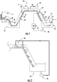
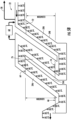
- a continuous vacuum chiller or vacuum chiller system 10 is illustrated by way of background in Figure 1 .
- the system includes inlet and outlet end portions 12, 14.
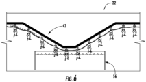
- the system includes a continuous conveying mechanism, for example a conveyor line 16 such as a belt 40 or shackle line 42 ( Figure 6 ), that conveys poultry products through the chiller from the inlet end portion 12 to the outlet end portion 14.
- the conveyor 16 may convey product P from a poultry product source 15 through an inlet water seal tank 18, up a first or inlet conduit 20, through a vacuum chamber 22, down a second or outlet conduit 24 and through an outlet water seal tank 26.
- a vacuum pump 44 or equivalent device is configured to evacuate the vacuum chamber 22 through a vacuum line 28.
- the inlet water seal 27 includes a lower water level 48 and an upper water level 50.
- the outlet water seal 29 includes a lower water level 52 and an upper water level 54.
- the seals 27, 29 extend up the first (inlet) and second (outlet) conduits 20, 24, respectively, with at least 10.4m (34 feet) of elevation gain. Due to the pressure differential between ambient atmosphere and the vacuum chamber, the water level on the vacuum side of the conduits 20, 24 is approximately 10.3m (404 inches) higher than the atmospheric side of the conduits 20, 24 and/or the seal tanks 18, 26 when the atmosphere is at nominal sea-level pressure.
- a U-trap or inverted weir 46 is in each of the inlet and outlet seal tanks 18, 26 to contain the water in the seal conduits.
- the inlet and outlet seal tanks 18, 26 have capacity to hold the full volume of seal water when the vacuum is not applied.
- the conveyor 16 enters the chiller at the atmospheric (short or low) side of the inlet water seal 27.
- the conveyor 16 passes under the weir 46 and up through the water in the first conduit 20 and emerges into the vacuum chamber 22 at the top.
- the conveyor 16 may follow a serpentine or other non-straight path to make efficient use of the space and to maximize the amount of product resident in the vacuum chamber 22.
- the vacuum chamber may be fitted with spray nozzles 38 or the like to keep the surfaces of the product moist.
- the conveyor 16 may periodically dip through a dip tank or water trough 56 ( Figure 6 ) in the vacuum chamber 22 to wet the product.
- the target temperature will generally be in the range of -3 and 0 °C (26 to 32 °F). Temperatures much lower will risk freezing the wings. Higher temperatures fail to fully utilize the advantages of the technology. However, temperatures as high as 2 °C (36 °F) may still be effective. Other temperatures may be appropriate for non-poultry products. At an operating temperature of -3 °C (28 °F), the difference between interior temperature and surface temperature would be 4 °C (8 °F) for a target interior temperature of 2 °C (36 °F). Thus, the heat transfer rate at the end of the process would be twice as fast as for immersion chilling. The difference in heat transfer rates during the early stages of chilling is less dramatic.
- the conveyor 16 exits the vacuum chamber 22 through the water column in the exit seal 29 that is generally identical to the inlet seal 27 except that the conveyor 16 enters at the high end and exits at the low end. It is contemplated that the system can be designed with a single seal, with the conveyor entering and exiting in parallel runs through the same conduit.
- a vacuum pump connected to vacuum line 28 has been described in reference to Figure 1 , it is contemplated that vacuum could be pulled using a mechanical pump, a steam eductor and/or a refrigerated condenser for condensing water vapor.
- a condenser 56 is illustrated inside the vacuum chamber 22. Refrigerant is supplied to the condenser through an inlet line 58 and removed through an outlet line 60. The refrigerant removes the heat of condensation as water vapor evaporated from the surface of the product condenses on the condenser.
- the condensate may be liquid water which will drain off of the condenser and removed from the vacuum chamber as through a drain 62.
- water vapor may condense as frost which must be periodically removed by defrosting the condenser.
- the condenser may also be located outside the vacuum chamber and connect to the chamber by a vacuum line 28.
- a condenser plate only removes water vapor and must be used in conjunction with some other device to remove air from the chamber.
- Water in the seal conduits may be mechanically refrigerated in addition to being chilled by evaporation at the vacuum end.
- a pump 30 could be used so that water from the outlet water seal tank 26 flows through a heat exchanger 32 for cooling the water, with the cooled water then flowing into the water seal 29 at or through the conduit 24.
- a cooling jacket 34 may surround at least a portion of the conduit 24.
- a pump 36 may be used so that water from the outlet water seal tank 26 is sent to spray nozzles 38 at or in the vacuum chamber 22.
- the spray nozzles 38 keep the product moist.
- the pump 36 and/or the spray nozzles 38 circulate the water through the outlet vacuum seal. It is contemplated that, in addition to the cooling from evaporation at the top end, such circulation may be adequate to maintain the temperature of the water substantially uniform. That is, the heat exchanger 32 and/or the cooling jacket 34 may be omitted in some embodiments.
- the spray nozzles 38 may receive water from a water source other than the outlet water seal tank.
- anti-microbial agents may be added to the water in one or both seals to reduce the possibility of product contamination.
- the vacuum chamber 22 or elevated portion of the system may run along the roof or in an overhead portion of the building and therefore does not take up valuable floor space.
- the vacuum portion of the chiller may be routed downwardly to a lower level.
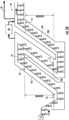
- An example of such downward routing might resemble the downwardly routed passageway 70 between the first and second water seal conduits of a two-stage water seal as illustrated in Figure 5A . From such a lower level, the vacuum portion would eventually rise upwardly to enter the outlet water seal.
- the system may be positioned in a hole or other cavity (e.g., in the factory floor) to reduce the height of the uppermost portion of the system.
- the vacuum seals 20 and 24 may be divided into two or more stages to reduce the overall height of the system.
- product would pass through a first stage inlet water seal 27A wherein the upper water surface 64 of the seal is elevated above the lower water surface 66 by nominally half of the 10.3m (404 inch) elevation difference previously noted for a single lift seal.
- the pressure of the atmosphere above this upper water surface is maintained at about 0.5 atmosphere of pressure by suitable vacuum devices.
- a pressure regulator 68 is shown in Figure 5A .
- the system may include a first inlet conduit 20A that is configured to hold the first inlet water seal 27A and a second inlet conduit 20B that is configured to hold the second inlet water seal 27B.
- Product emerging from the top of the first stage seal 27A is then conveyed at constant pressure down through an intermediate conduit or passageway 70 to the inlet of the second stage of the seal 27B which is constructed much like the first stage seal 27A.
- the upper water level 72 of the second stage may be about 5.1m (202 inches) above the lower water surface 74.
- the atmosphere above the upper water surface of the second stage seal is at very low pressure as described previously. From this point, the process proceeds as before until the product reaches the outlet water seal.
- the outlet seal consists of two stages through which product passes in reverse sequence of the 2-stage inlet seal.
- the system may include a first outlet conduit 24A configured to hold a first outlet water seal 29A and a second outlet conduit 24B configured to hold a second outlet water seal 29B.
- An intermediate conduit or passageway 76 generally corresponding to the conduit or passageway 70 described above is disposed between the first and second outlet conduits 24A, 24B.
- multiple seal stages may have varying elevation changes so long as the sum of the changes for all stages is approximately 10.3m (404 inches).
- the system may be generally embodied as shown in Figure 5A . More specifically, the system may include a first conduit 27A and a second conduit 27B with an intermediate passageway 70 disposed therebetween and communicating with each of the first and second conduits 27A, 27B.
- a first water seal 27A is held in the first conduit 20A and a second water seal 27B is held in the second conduit 20B.
- the product is conveyed up through the first conduit 20A, then down through the intermediate passageway 70, then up through the second conduit 20B, then into and through the vacuum chamber 22 for chilling.
- the chilled product is then conveyed out of the vacuum chamber 22 and down through the second conduit 20B, then up through the intermediate passageway 70, and then down through the first conduit 20A.
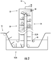
- the inlet and outlet conduits 20, 24 may be vertical. Moreover, there may be only one water seal and only one water seal holding tank. This is illustrated in Figure 3 with the combined tank 18, 26 and the combined water seal 27, 29.
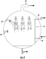
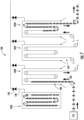
- Vacuum chilling systems operate in a batch mode.
- a batch vacuum chilling system 100 includes a plurality of vacuum chambers, which are sequentially loaded, evacuated, held in vacuum for a time and then unloaded.
- An empty chamber 102C contains a conveying mechanism such as a shackle line 104 that has no product attached.
- a vacuum chamber 102B is loaded by conveying product into the chamber.
- the conveying mechanism 108 e.g., a shackle line
- the conveying mechanism is disconnected from the main line or otherwise stopped and remains in the chamber.
- the conveyance coming from the evisceration process or poultry product source 115 is then directed into a different chamber.
- the filled chamber is then closed and evacuated through vacuum line 128 by opening valve 130 as shown with chamber 102A.
- the evacuated chamber is held at low pressure for sufficient time to reduce the temperature of the product.
- the chamber 102D is opened and the conveyor portion is reconnected to the main line or otherwise restarted so that the chilled birds may be conveyed to the next processing step.
- a plurality of chambers may be provided so that they may be loaded sequentially in an approximation of a continuous process.
- spray heads 80 ( Figure 4 ) may be mounted at intervals so that cleaning solution and rinse water may be applied to the interior surfaces of the vacuum chamber and seals.
Landscapes
- Engineering & Computer Science (AREA)
- Life Sciences & Earth Sciences (AREA)
- Food Science & Technology (AREA)
- Chemical & Material Sciences (AREA)
- Zoology (AREA)
- Wood Science & Technology (AREA)
- Polymers & Plastics (AREA)
- Mechanical Engineering (AREA)
- General Chemical & Material Sciences (AREA)
- Chemical Kinetics & Catalysis (AREA)
- Combustion & Propulsion (AREA)
- Physics & Mathematics (AREA)
- Thermal Sciences (AREA)
- General Engineering & Computer Science (AREA)
- Processing Of Meat And Fish (AREA)
Claims (16)
- System zur Vakuumkühlung von Geflügelprodukten, wobei das System Folgendes umfasst:eine Vakuumkammer (22), konfiguriert zum Evakuieren zum Kühlen des Geflügelprodukts in der Vakuumkammer;mindestens eine mit der Vakuumkammer gekoppelte geneigte oder vertikale Leitung (20), wobei die mindestens eine Leitung zum Halten mindestens einer Wasserdichtung (27) konfiguriert ist, wenn die Vakuumkammer evakuiert wird; undeinen Fördermechanismus (16), konfiguriert zum kontinuierlichen Befördern des Geflügelprodukts nach oben durch die mindestens eine Leitung, dann in und durch die Vakuumkammer und dann nach unten durch die mindestens eine Leitung,wobei:die mindestens eine Leitung (20) eine sich nach oben zur Vakuumkammer erstreckende geneigte oder vertikale Einlassleitung an einem ersten Endabschnitt des Systems und eine sich von der Vakuumkammer nach unten erstreckende geneigte oder vertikale Auslassleitung (24) an einem zweiten Endabschnitt des Systems umfasst;die mindestens eine Wasserdichtung eine Einlasswasserdichtung (27) und eine Auslasswasserdichtung (29) umfasst;die Einlassleitung zum Halten der Einlasswasserdichtung konfiguriert ist, wenn die Vakuumkammer evakuiert wird;die Auslassleitung zum Halten der Auslasswasserdichtung konfiguriert ist, wenn die Vakuumkammer evakuiert wird; undder Fördermechanismus (16) zum kontinuierlichen Befördern des Geflügelprodukts nach oben durch die Einlassleitung, dann in und durch die Vakuumkammer und dann nach unten durch die Auslassleitung konfiguriert ist,dadurch gekennzeichnet, dass:die Einlassleitung eine erste Einlassleitung (20A) und eine zweite Einlassleitung (20B) mit einem dazwischen angeordneten Zwischeneinlassdurchgang (70) umfasst, der jeweils mit der ersten und zweiten Einlassleitung in Verbindung steht;die Einlasswasserdichtung eine erste Einlasswasserdichtung (27A) und eine zweite Einlasswasserdichtung (27B) umfasst;die erste Einlassleitung zum Halten der ersten Einlasswasserdichtung konfiguriert ist, wenn die Vakuumkammer evakuiert wird;die zweite Einlassleitung zum Halten der zweiten Einlasswasserdichtung konfiguriert ist, wenn die Vakuumkammer evakuiert wird;die Auslassleitung eine erste Auslassleitung (24A) und eine zweite Auslassleitung (24B) mit einem dazwischen angeordneten Zwischenauslassdurchgang (76) umfasst, der jeweils mit der ersten und zweiten Auslassleitung in Verbindung steht;die Auslasswasserdichtung eine erste Auslasswasserdichtung (29A) und eine zweite Auslasswasserdichtung (29B) umfasst;die erste Auslassleitung zum Halten der ersten Auslasswasserdichtung konfiguriert ist, wenn die Vakuumkammer evakuiert wird;die zweite Auslassleitung zum Halten der zweiten Auslasswasserdichtung konfiguriert ist, wenn die Vakuumkammer evakuiert wird; undder Fördermechanismus zum kontinuierlichen Befördern des Geflügelprodukts nach oben durch die erste Einlassleitung, dann nach unten durch den Zwischeneinlassdurchgang, dann nach oben durch die zweite Einlassleitung, dann in und durch die Vakuumkammer, dann nach unten durch die zweite Auslassleitung, dann nach oben durch den Zwischenauslassdurchgang und dann nach unten durch die erste Auslassleitung konfiguriert ist.
- System nach Anspruch 1, das ferner Folgendes umfasst:einen ersten Wasserdichtungstank (18) am ersten Endabschnitt des Systems, der zum Halten der Einlasswasserdichtung konfiguriert ist, wenn die Vakuumkammer evakuiert wird; undeinen zweiten Wasserdichtungstank (26) am zweiten Endabschnitt des Systems, der zum Halten der Auslasswasserdichtung konfiguriert ist, wenn die Vakuumkammer evakuiert wird.
- System nach Anspruch 1 oder 2, das ferner Folgendes umfasst:
einen Wärmetauscher (32), der zum mechanischen Kühlen des Wassers in der Auslasswasserdichtung konfiguriert ist. - System zum Vakuumkühlen von Geflügelprodukten, wobei das System Folgendes umfasst:eine Vakuumkammer (22), konfiguriert zum Evakuieren zum Kühlen des Geflügelprodukts in der Vakuumkammer;mindestens eine mit der Vakuumkammer gekoppelte geneigte oder vertikale Leitung, wobei die mindestens eine Leitung zum Halten mindestens einer Wasserdichtung konfiguriert ist, wenn die Vakuumkammer evakuiert wird; undeinen Fördermechanismus (16), der zum kontinuierlichen Befördern des Geflügelprodukts nach oben durch die mindestens eine Leitung, dann in und durch die Vakuumkammer und dann nach unten durch die mindestens eine Leitung konfiguriert ist,dadurch gekennzeichnet, dass:die mindestens eine Leitung eine erste Leitung (20A) und eine zweite Leitung (20B) mit einem dazwischen angeordneten Zwischendurchgang (70) umfasst, der jeweils mit der ersten und zweiten Leitung in Verbindung steht;die mindestens eine Wasserdichtung eine erste Wasserdichtung (27A) und eine zweite Wasserdichtung (27B) umfasst;die erste Leitung zum Halten der ersten Wasserdichtung konfiguriert ist, wenn die Vakuumkammer evakuiert wird;die zweite Leitung zum Halten der zweiten Wasserdichtung konfiguriert ist, wenn die Vakuumkammer evakuiert wird; undder Fördermechanismus zum kontinuierlichen Befördern des Geflügelprodukts nach oben durch die erste Leitung, dann nach unten durch den Zwischendurchgang, dann nach oben durch die zweite Leitung, dann in und durch die Vakuumkammer, dann nach unten durch die zweite Leitung, dann nach oben durch den Zwischendurchgang und dann nach unten durch die erste Leitung konfiguriert ist.
- System nach einem vorherigen Anspruch, das ferner mindestens einen Druckregler (68) umfasst, der im Falle der Ansprüche 1-3 zum Reduzieren des Drucks in jedem der Zwischeneinlass- und -auslasskanäle oder, im Falle von Anspruch 4, zum Reduzieren des Drucks im Zwischendurchgang konfiguriert ist.
- System nach einem vorherigen Anspruch, das ferner eine oder mehrere Düsen (38) umfasst, die zum Sprühen von Wasser auf durch die Vakuumkammer befördertes Geflügelprodukt konfiguriert sind.
- System nach einem vorherigen Anspruch, das ferner einen gekühlten Kondensator (56) umfasst, der zum Aufnehmen von Kühlmittel dadurch in der Vakuumkammer konfiguriert ist.
- System nach einem der Ansprüche 1 bis 5, das ferner einen Eintauchtank (56) zum Halten von Wasser in der Vakuumkammer umfasst, wobei der Fördermechanismus das Geflügelprodukt in der Vakuumkammer nach unten befördert, so dass das Geflügelprodukt durch das Wasser im Eintauchtank läuft.
- Verfahren zum Vakuumkühlen von Geflügelprodukten in einem kontinuierlichen Modus, wobei das Verfahren Folgendes beinhaltet:Evakuieren einer Vakuumkammer (22);Befördern des Geflügelprodukts mindestens eine mindestens eine Wasserdichtung (27) enthaltende geneigte oder vertikale Einlassleitung (20) hinauf; dannBefördern des Geflügelprodukts in und durch die mit der mindestens einen Leitung verbundene Vakuumkammer zum Kühlen des Geflügelprodukts; und dannBefördern des gekühlten Geflügelprodukts die mindestens eine Leitung hinunter,wobei:die mindestens eine Leitung eine sich nach oben zur Vakuumkammer erstreckende geneigte oder vertikale Einlassleitung und eine sich von der Vakuumkammer nach unten erstreckende geneigte oder vertikale Auslassleitung umfasst;die mindestens eine Wasserdichtung eine in der Einlassleitung gehaltene Einlasswasserdichtung und eine in der Auslassleitung gehaltene Auslasswasserdichtung umfasst; unddas Verfahren Folgendes beinhaltet:Befördern des Geflügelprodukts die Einlassleitung hinauf; dannBefördern des Geflügelprodukts in und durch die Vakuumkammer; und dannBefördern des gekühlten Geflügelprodukts die Auslassleitung hinunter, dadurch gekennzeichnet, dass:die Einlassleitung eine erste Einlassleitung (20A) und eine zweite Einlassleitung (20B) mit einem dazwischen angeordneten Zwischeneinlassdurchgang (70) umfasst, der jeweils mit der ersten und zweiten Einlassleitung in Verbindung steht;die Einlasswasserdichtung eine in der ersten Einlassleitung gehaltene erste Einlasswasserdichtung (27A) und eine in der zweiten Einlassleitung gehaltene zweite Einlasswasserdichtung (27B) umfasst;die Auslassleitung eine erste Auslassleitung (24A) und eine zweite Auslassleitung (24B) mit einem dazwischen angeordneten Zwischenauslassdurchgang (76) umfasst, der jeweils mit der ersten und zweiten Auslassleitung in Verbindung steht;die Auslasswasserdichtung eine in der ersten Auslassleitung gehaltene erste Auslasswasserdichtung (29A) und eine in der zweiten Auslassleitung gehaltene zweite Auslasswasserdichtung (29B) umfasst;und das Verfahren Folgendes beinhaltet:Befördern des Geflügelprodukts die erste Einlassleitung hinauf; dannBefördern des Geflügelprodukts den Zwischeneinlassdurchgang hinunter; dannBefördern des Geflügelprodukts die zweite Einlassleitung hinauf; dannBefördern des Geflügelprodukts in und durch die Vakuumkammer; dannBefördern des gekühlten Geflügelprodukts die zweite Auslassleitung hinunter; dannBefördern des gekühlten Geflügelprodukts den Zwischenauslassdurchgang hinauf; und dannBefördern des gekühlten Geflügelprodukts die erste Auslassleitung hinunter.
- Verfahren nach Anspruch 9, das ferner Folgendes beinhaltet:Befördern des Geflügelprodukts durch einen die erste Einlasswasserdichtung haltenden Einlasswasserdichtungstank (18) vor dem Befördern des Geflügelprodukts die erste Einlassleitung hinauf; undBefördern des gekühlten Geflügelprodukts durch einen die erste Auslasswasserdichtung haltenden Auslasswasserdichtungsbehälter (26) nach dem Befördern des Geflügelprodukts die erste Auslassleitung hinunter.
- Verfahren nach Anspruch 9 oder 10, das ferner Folgendes beinhaltet:
mechanisches Kühlen von Wasser in der Auslasswasserdichtung. - Verfahren zum Vakuumkühlen von Geflügelprodukten in einem kontinuierlichen Modus, wobei das Verfahren Folgendes beinhaltet:Evakuieren einer Vakuumkammer (22);Befördern des Geflügelprodukts mindestens eine mindestens eine Wasserdichtung enthaltende geneigte oder vertikale Einlassleitung hinauf; dannBefördern des Geflügelprodukts in und durch die mit der mindestens einen Leitung gekoppelten Vakuumkammer zum Kühlen des Geflügelprodukts; und dannBefördern des gekühlten Geflügelprodukts die mindestens eine Leitung hinunter,dadurch gekennzeichnet, dass:die mindestens eine Leitung eine erste Leitung (20A) und eine zweite Leitung (20B) mit einem dazwischen angeordneten Zwischendurchgang (70) umfasst, der jeweils mit der ersten und zweiten Leitung in Verbindung steht;die mindestens eine Wasserdichtung eine in der ersten Leitung gehaltene erste Wasserdichtung (27A) und eine in der zweiten Leitung gehaltene zweite Wasserdichtung (27B) umfasst; unddas Verfahren Folgendes beinhaltet:Befördern des Geflügelprodukts die erste Leitung hinauf; dannBefördern des Geflügelprodukts den Zwischendurchgang hinunter; dannBefördern des Geflügelprodukts die zweite Leitung hinauf; dannBefördern des Geflügelprodukts in und durch die Vakuumkammer; dannBefördern des gekühlten Geflügelprodukts die zweite Leitung hinunter; dannBefördern des gekühlten Geflügelprodukts den Zwischendurchgang hinunter; und dannBefördern des gekühlten Geflügelprodukts die erste Leitung hinunter.
- Verfahren nach einem der Ansprüche 9 bis 12, das ferner, mittels mindestens einen Druckreglers (68), das Reduzieren des Drucks in jedem der Zwischeneinlass- und - auslasskanäle im Falle der Ansprüche 9 bis 11 oder, im Falle von Anspruch 12, im Zwischendurchgang beinhaltet.
- Verfahren nach einem der Ansprüche 9 bis 13, das ferner das Sprühen von Wasser aus einer oder mehreren Sprühdüsen (38) auf das Geflügelprodukt in der Vakuumkammer beinhaltet.
- Verfahren nach einem der Ansprüche 9 bis 14, das ferner das Befördern des Geflügelprodukts in der Vakuumkammer nach unten beinhaltet, so dass es durch das Wasser in einem Eintauchbehälter (56) läuft.
- Verfahren nach einem der Ansprüche 9 bis 15, das ferner das Aufnehmen von Kühlmittel durch einen Kondensator (56) in der Vakuumkammer beinhaltet.
Applications Claiming Priority (2)
| Application Number | Priority Date | Filing Date | Title |
|---|---|---|---|
| US201662338179P | 2016-05-18 | 2016-05-18 | |
| PCT/US2017/033355 WO2017201303A1 (en) | 2016-05-18 | 2017-05-18 | Systems and methods for vacuum chilling poultry products |
Publications (3)
| Publication Number | Publication Date |
|---|---|
| EP3439481A1 EP3439481A1 (de) | 2019-02-13 |
| EP3439481C0 EP3439481C0 (de) | 2024-09-11 |
| EP3439481B1 true EP3439481B1 (de) | 2024-09-11 |
Family
ID=58995251
Family Applications (1)
| Application Number | Title | Priority Date | Filing Date |
|---|---|---|---|
| EP17727775.3A Active EP3439481B1 (de) | 2016-05-18 | 2017-05-18 | Systeme und verfahren zur vakuumkühlung von geflügelprodukten |
Country Status (4)
| Country | Link |
|---|---|
| US (1) | US10653157B2 (de) |
| EP (1) | EP3439481B1 (de) |
| CN (1) | CN109640673B (de) |
| WO (1) | WO2017201303A1 (de) |
Families Citing this family (8)
| Publication number | Priority date | Publication date | Assignee | Title |
|---|---|---|---|---|
| AU2016345054B2 (en) | 2015-10-27 | 2022-12-01 | Cos Ipt Pty Ltd | Apparatus for storing organic material |
| US11432579B2 (en) | 2017-03-30 | 2022-09-06 | Robert G. Nothum, Jr. | Internal washing provisions for food process line machines |
| US20200393283A1 (en) | 2017-03-30 | 2020-12-17 | Robert G. Nothum, Jr. | Production flow-rate measurement options for food process lines |
| US20210205835A1 (en) | 2017-03-30 | 2021-07-08 | Robert G. Nothum, Jr. | Work-saving improvements for food-process lines |
| WO2021188691A1 (en) * | 2020-03-17 | 2021-09-23 | John Bean Technologies Corporation | Whole bird chiller clean in place |
| EP4247170A4 (de) * | 2020-12-16 | 2024-08-21 | Provisur Technologies, Inc. | Schneid- und verpackungsanordnung mit modifizierter atmosphäre |
| EP4322751A1 (de) | 2021-04-16 | 2024-02-21 | Interroll Holding AG | Fördervorrichtung |
| CN119908389B (zh) * | 2025-04-01 | 2025-08-01 | 胜田(福清)食品有限公司 | 一种肉类食品加工用解冻装置及解冻方法 |
Family Cites Families (13)
| Publication number | Priority date | Publication date | Assignee | Title |
|---|---|---|---|---|
| US2787141A (en) * | 1953-05-18 | 1957-04-02 | Julius Michael | Method and apparatus for precooling produce |
| US3423950A (en) * | 1966-12-28 | 1969-01-28 | Croll Reynolds Co Inc | Vacuum cooling apparatus |
| NL8900953A (nl) * | 1989-04-17 | 1990-11-16 | Micon Milieuconsultants | Werkwijze en inrichting voor het drogen en/of koelen van een produkt dat een of meer verdampbare stoffen bevat. |
| US4942053A (en) | 1989-07-19 | 1990-07-17 | Geo. A. Hormel & Company | Vacuum chilling for processing meat |
| DK484689A (da) * | 1989-09-29 | 1991-03-30 | Slagteriernes Forskningsinst | Fremgangsmaade ved udtagning eller behandling af indvolde fra svineslagtekroppe |
| US6796892B2 (en) * | 2000-11-03 | 2004-09-28 | Excel Corporation | Method and apparatus for processing carcasses |
| US8684799B2 (en) * | 2006-12-08 | 2014-04-01 | Diversey, Inc. | Cleaning apparatus and method |
| CN201163983Y (zh) * | 2008-01-14 | 2008-12-17 | 陈长清 | 集装式连续真空预冷加工设备 |
| US8376815B1 (en) * | 2008-04-30 | 2013-02-19 | Perdue Holdings, Inc. | Method and apparatus for electrical stimulation of meat |
| US9062333B2 (en) * | 2009-08-14 | 2015-06-23 | Environmental Quality Management Associates | Method and apparatus for transforming waste into fuel ethanol |
| RU2482755C1 (ru) * | 2011-12-23 | 2013-05-27 | Федеральное государственное бюджетное образовательное учреждение высшего профессионального образования Воронежский государственный университет инженерных технологий (ФГБОУ ВПО ВГУИТ) | Способ производства пищевых продуктов с применением теплового насоса |
| CN104921189B (zh) * | 2015-06-30 | 2018-07-24 | 湖北洪湖渔家水产食品有限公司 | 一种清水小龙虾的加工方法 |
| CN105497927A (zh) * | 2015-12-10 | 2016-04-20 | 诸城市安泰机械有限公司 | 连续式高温灭菌方法及其使用的灭菌罐 |
-
2017
- 2017-05-18 US US16/302,176 patent/US10653157B2/en active Active
- 2017-05-18 EP EP17727775.3A patent/EP3439481B1/de active Active
- 2017-05-18 CN CN201780044352.9A patent/CN109640673B/zh active Active
- 2017-05-18 WO PCT/US2017/033355 patent/WO2017201303A1/en not_active Ceased
Also Published As
| Publication number | Publication date |
|---|---|
| CN109640673B (zh) | 2021-12-31 |
| WO2017201303A1 (en) | 2017-11-23 |
| US10653157B2 (en) | 2020-05-19 |
| EP3439481C0 (de) | 2024-09-11 |
| CN109640673A (zh) | 2019-04-16 |
| EP3439481A1 (de) | 2019-02-13 |
| BR112018072763A2 (pt) | 2019-02-19 |
| US20190274320A1 (en) | 2019-09-12 |
Similar Documents
| Publication | Publication Date | Title |
|---|---|---|
| EP3439481B1 (de) | Systeme und verfahren zur vakuumkühlung von geflügelprodukten | |
| US4367630A (en) | System for rapidly chilling carcasses | |
| US4325221A (en) | Method and apparatus for reducing the temperature of articles | |
| US2065358A (en) | Method of chilling animal carcasses | |
| US20030041614A1 (en) | Continuous throughput blast freezer | |
| NO153216B (no) | Stroemningsfordeler. | |
| WO1991017400A1 (en) | Food freezer | |
| WO2009151191A1 (en) | Multifloor tunnel type freezing method and the refrigerant | |
| US5417074A (en) | Liquid nitrogen immersion/impingement freezing method and apparatus | |
| KR101621012B1 (ko) | 절임 배추 제조방법 및 저장방법 | |
| Khadatkar et al. | Cryofreezing and cryofreezer | |
| KR101332273B1 (ko) | 냉장고 | |
| CN107202461A (zh) | 一种液氮冷冻设备的液氮控制系统 | |
| US4319460A (en) | High humidity food chilling system | |
| US3605427A (en) | Method and apparatus for extracting heat from articles with an ebullient liquid freezant | |
| US3423950A (en) | Vacuum cooling apparatus | |
| US6305184B1 (en) | Cooling tunnel for eggs | |
| CN112568264A (zh) | 一种用于家禽屠宰的冷链运输机构 | |
| US5173316A (en) | Method for preparing fish bait | |
| US20150308726A1 (en) | Method and apparatus for recovering cryogens | |
| EP1511390B1 (de) | Verfahren und vorrichtung zum kühlen von schlachttieren und schlachttierkörperteilen | |
| Davidge | Cryogenics in the food industry | |
| GB2526634A (en) | Cryogenic treatment apparatus and method for campylobacter | |
| KR20210140900A (ko) | 농산물의 진공 냉각장치 및 방법 | |
| RU2655758C1 (ru) | Установка для охлаждения рыбы на рыбодобывающих судах |
Legal Events
| Date | Code | Title | Description |
|---|---|---|---|
| STAA | Information on the status of an ep patent application or granted ep patent |
Free format text: STATUS: UNKNOWN |
|
| STAA | Information on the status of an ep patent application or granted ep patent |
Free format text: STATUS: THE INTERNATIONAL PUBLICATION HAS BEEN MADE |
|
| PUAI | Public reference made under article 153(3) epc to a published international application that has entered the european phase |
Free format text: ORIGINAL CODE: 0009012 |
|
| STAA | Information on the status of an ep patent application or granted ep patent |
Free format text: STATUS: REQUEST FOR EXAMINATION WAS MADE |
|
| 17P | Request for examination filed |
Effective date: 20181105 |
|
| AK | Designated contracting states |
Kind code of ref document: A1 Designated state(s): AL AT BE BG CH CY CZ DE DK EE ES FI FR GB GR HR HU IE IS IT LI LT LU LV MC MK MT NL NO PL PT RO RS SE SI SK SM TR |
|
| AX | Request for extension of the european patent |
Extension state: BA ME |
|
| DAV | Request for validation of the european patent (deleted) | ||
| DAX | Request for extension of the european patent (deleted) | ||
| STAA | Information on the status of an ep patent application or granted ep patent |
Free format text: STATUS: EXAMINATION IS IN PROGRESS |
|
| 17Q | First examination report despatched |
Effective date: 20211118 |
|
| GRAP | Despatch of communication of intention to grant a patent |
Free format text: ORIGINAL CODE: EPIDOSNIGR1 |
|
| STAA | Information on the status of an ep patent application or granted ep patent |
Free format text: STATUS: GRANT OF PATENT IS INTENDED |
|
| INTG | Intention to grant announced |
Effective date: 20240405 |
|
| GRAS | Grant fee paid |
Free format text: ORIGINAL CODE: EPIDOSNIGR3 |
|
| GRAA | (expected) grant |
Free format text: ORIGINAL CODE: 0009210 |
|
| STAA | Information on the status of an ep patent application or granted ep patent |
Free format text: STATUS: THE PATENT HAS BEEN GRANTED |
|
| AK | Designated contracting states |
Kind code of ref document: B1 Designated state(s): AL AT BE BG CH CY CZ DE DK EE ES FI FR GB GR HR HU IE IS IT LI LT LU LV MC MK MT NL NO PL PT RO RS SE SI SK SM TR |
|
| REG | Reference to a national code |
Ref country code: GB Ref legal event code: FG4D |
|
| REG | Reference to a national code |
Ref country code: CH Ref legal event code: EP |
|
| REG | Reference to a national code |
Ref country code: DE Ref legal event code: R096 Ref document number: 602017084780 Country of ref document: DE |
|
| REG | Reference to a national code |
Ref country code: IE Ref legal event code: FG4D |
|
| U01 | Request for unitary effect filed |
Effective date: 20240920 |
|
| U07 | Unitary effect registered |
Designated state(s): AT BE BG DE DK EE FI FR IT LT LU LV MT NL PT RO SE SI Effective date: 20241015 |
|
| PG25 | Lapsed in a contracting state [announced via postgrant information from national office to epo] |
Ref country code: NO Free format text: LAPSE BECAUSE OF FAILURE TO SUBMIT A TRANSLATION OF THE DESCRIPTION OR TO PAY THE FEE WITHIN THE PRESCRIBED TIME-LIMIT Effective date: 20241211 |
|
| PG25 | Lapsed in a contracting state [announced via postgrant information from national office to epo] |
Ref country code: GR Free format text: LAPSE BECAUSE OF FAILURE TO SUBMIT A TRANSLATION OF THE DESCRIPTION OR TO PAY THE FEE WITHIN THE PRESCRIBED TIME-LIMIT Effective date: 20241212 |
|
| PG25 | Lapsed in a contracting state [announced via postgrant information from national office to epo] |
Ref country code: HR Free format text: LAPSE BECAUSE OF FAILURE TO SUBMIT A TRANSLATION OF THE DESCRIPTION OR TO PAY THE FEE WITHIN THE PRESCRIBED TIME-LIMIT Effective date: 20240911 |
|
| PG25 | Lapsed in a contracting state [announced via postgrant information from national office to epo] |
Ref country code: RS Free format text: LAPSE BECAUSE OF FAILURE TO SUBMIT A TRANSLATION OF THE DESCRIPTION OR TO PAY THE FEE WITHIN THE PRESCRIBED TIME-LIMIT Effective date: 20241211 Ref country code: ES Free format text: LAPSE BECAUSE OF FAILURE TO SUBMIT A TRANSLATION OF THE DESCRIPTION OR TO PAY THE FEE WITHIN THE PRESCRIBED TIME-LIMIT Effective date: 20240911 |
|
| PG25 | Lapsed in a contracting state [announced via postgrant information from national office to epo] |
Ref country code: RS Free format text: LAPSE BECAUSE OF FAILURE TO SUBMIT A TRANSLATION OF THE DESCRIPTION OR TO PAY THE FEE WITHIN THE PRESCRIBED TIME-LIMIT Effective date: 20241211 Ref country code: NO Free format text: LAPSE BECAUSE OF FAILURE TO SUBMIT A TRANSLATION OF THE DESCRIPTION OR TO PAY THE FEE WITHIN THE PRESCRIBED TIME-LIMIT Effective date: 20241211 Ref country code: HR Free format text: LAPSE BECAUSE OF FAILURE TO SUBMIT A TRANSLATION OF THE DESCRIPTION OR TO PAY THE FEE WITHIN THE PRESCRIBED TIME-LIMIT Effective date: 20240911 Ref country code: GR Free format text: LAPSE BECAUSE OF FAILURE TO SUBMIT A TRANSLATION OF THE DESCRIPTION OR TO PAY THE FEE WITHIN THE PRESCRIBED TIME-LIMIT Effective date: 20241212 Ref country code: ES Free format text: LAPSE BECAUSE OF FAILURE TO SUBMIT A TRANSLATION OF THE DESCRIPTION OR TO PAY THE FEE WITHIN THE PRESCRIBED TIME-LIMIT Effective date: 20240911 |
|
| PG25 | Lapsed in a contracting state [announced via postgrant information from national office to epo] |
Ref country code: IS Free format text: LAPSE BECAUSE OF FAILURE TO SUBMIT A TRANSLATION OF THE DESCRIPTION OR TO PAY THE FEE WITHIN THE PRESCRIBED TIME-LIMIT Effective date: 20250111 |
|
| PG25 | Lapsed in a contracting state [announced via postgrant information from national office to epo] |
Ref country code: SM Free format text: LAPSE BECAUSE OF FAILURE TO SUBMIT A TRANSLATION OF THE DESCRIPTION OR TO PAY THE FEE WITHIN THE PRESCRIBED TIME-LIMIT Effective date: 20240911 |
|
| PG25 | Lapsed in a contracting state [announced via postgrant information from national office to epo] |
Ref country code: PL Free format text: LAPSE BECAUSE OF FAILURE TO SUBMIT A TRANSLATION OF THE DESCRIPTION OR TO PAY THE FEE WITHIN THE PRESCRIBED TIME-LIMIT Effective date: 20240911 Ref country code: CZ Free format text: LAPSE BECAUSE OF FAILURE TO SUBMIT A TRANSLATION OF THE DESCRIPTION OR TO PAY THE FEE WITHIN THE PRESCRIBED TIME-LIMIT Effective date: 20240911 |
|
| PG25 | Lapsed in a contracting state [announced via postgrant information from national office to epo] |
Ref country code: SK Free format text: LAPSE BECAUSE OF FAILURE TO SUBMIT A TRANSLATION OF THE DESCRIPTION OR TO PAY THE FEE WITHIN THE PRESCRIBED TIME-LIMIT Effective date: 20240911 |
|
| U20 | Renewal fee for the european patent with unitary effect paid |
Year of fee payment: 9 Effective date: 20250407 |
|
| PLBE | No opposition filed within time limit |
Free format text: ORIGINAL CODE: 0009261 |
|
| STAA | Information on the status of an ep patent application or granted ep patent |
Free format text: STATUS: NO OPPOSITION FILED WITHIN TIME LIMIT |
|
| 26N | No opposition filed |
Effective date: 20250612 |
|
| REG | Reference to a national code |
Ref country code: CH Ref legal event code: H13 Free format text: ST27 STATUS EVENT CODE: U-0-0-H10-H13 (AS PROVIDED BY THE NATIONAL OFFICE) Effective date: 20251223 |
|
| PG25 | Lapsed in a contracting state [announced via postgrant information from national office to epo] |
Ref country code: CH Free format text: LAPSE BECAUSE OF NON-PAYMENT OF DUE FEES Effective date: 20250531 |
|
| GBPC | Gb: european patent ceased through non-payment of renewal fee |
Effective date: 20250518 |
|
| PG25 | Lapsed in a contracting state [announced via postgrant information from national office to epo] |
Ref country code: MC Free format text: LAPSE BECAUSE OF FAILURE TO SUBMIT A TRANSLATION OF THE DESCRIPTION OR TO PAY THE FEE WITHIN THE PRESCRIBED TIME-LIMIT Effective date: 20240911 |