EP3439071A1 - Manufacturing method of separator for fuel cell - Google Patents
Manufacturing method of separator for fuel cell Download PDFInfo
- Publication number
- EP3439071A1 EP3439071A1 EP18178325.9A EP18178325A EP3439071A1 EP 3439071 A1 EP3439071 A1 EP 3439071A1 EP 18178325 A EP18178325 A EP 18178325A EP 3439071 A1 EP3439071 A1 EP 3439071A1
- Authority
- EP
- European Patent Office
- Prior art keywords
- convex
- convex surface
- metal plate
- separator
- concave surface
- Prior art date
- Legal status (The legal status is an assumption and is not a legal conclusion. Google has not performed a legal analysis and makes no representation as to the accuracy of the status listed.)
- Withdrawn
Links
Images



Classifications
-
- H—ELECTRICITY
- H01—ELECTRIC ELEMENTS
- H01M—PROCESSES OR MEANS, e.g. BATTERIES, FOR THE DIRECT CONVERSION OF CHEMICAL ENERGY INTO ELECTRICAL ENERGY
- H01M8/00—Fuel cells; Manufacture thereof
- H01M8/02—Details
- H01M8/0202—Collectors; Separators, e.g. bipolar separators; Interconnectors
- H01M8/0269—Separators, collectors or interconnectors including a printed circuit board
-
- H—ELECTRICITY
- H01—ELECTRIC ELEMENTS
- H01M—PROCESSES OR MEANS, e.g. BATTERIES, FOR THE DIRECT CONVERSION OF CHEMICAL ENERGY INTO ELECTRICAL ENERGY
- H01M8/00—Fuel cells; Manufacture thereof
- H01M8/02—Details
- H01M8/0202—Collectors; Separators, e.g. bipolar separators; Interconnectors
- H01M8/0247—Collectors; Separators, e.g. bipolar separators; Interconnectors characterised by the form
- H01M8/0254—Collectors; Separators, e.g. bipolar separators; Interconnectors characterised by the form corrugated or undulated
-
- H—ELECTRICITY
- H01—ELECTRIC ELEMENTS
- H01M—PROCESSES OR MEANS, e.g. BATTERIES, FOR THE DIRECT CONVERSION OF CHEMICAL ENERGY INTO ELECTRICAL ENERGY
- H01M8/00—Fuel cells; Manufacture thereof
- H01M8/02—Details
- H01M8/0202—Collectors; Separators, e.g. bipolar separators; Interconnectors
- H01M8/0258—Collectors; Separators, e.g. bipolar separators; Interconnectors characterised by the configuration of channels, e.g. by the flow field of the reactant or coolant
-
- B—PERFORMING OPERATIONS; TRANSPORTING
- B29—WORKING OF PLASTICS; WORKING OF SUBSTANCES IN A PLASTIC STATE IN GENERAL
- B29C—SHAPING OR JOINING OF PLASTICS; SHAPING OF MATERIAL IN A PLASTIC STATE, NOT OTHERWISE PROVIDED FOR; AFTER-TREATMENT OF THE SHAPED PRODUCTS, e.g. REPAIRING
- B29C51/00—Shaping by thermoforming, i.e. shaping sheets or sheet like preforms after heating, e.g. shaping sheets in matched moulds or by deep-drawing; Apparatus therefor
- B29C51/14—Shaping by thermoforming, i.e. shaping sheets or sheet like preforms after heating, e.g. shaping sheets in matched moulds or by deep-drawing; Apparatus therefor using multilayered preforms or sheets
-
- B—PERFORMING OPERATIONS; TRANSPORTING
- B29—WORKING OF PLASTICS; WORKING OF SUBSTANCES IN A PLASTIC STATE IN GENERAL
- B29C—SHAPING OR JOINING OF PLASTICS; SHAPING OF MATERIAL IN A PLASTIC STATE, NOT OTHERWISE PROVIDED FOR; AFTER-TREATMENT OF THE SHAPED PRODUCTS, e.g. REPAIRING
- B29C59/00—Surface shaping of articles, e.g. embossing; Apparatus therefor
- B29C59/02—Surface shaping of articles, e.g. embossing; Apparatus therefor by mechanical means, e.g. pressing
- B29C59/022—Surface shaping of articles, e.g. embossing; Apparatus therefor by mechanical means, e.g. pressing characterised by the disposition or the configuration, e.g. dimensions, of the embossments or the shaping tools therefor
-
- B—PERFORMING OPERATIONS; TRANSPORTING
- B32—LAYERED PRODUCTS
- B32B—LAYERED PRODUCTS, i.e. PRODUCTS BUILT-UP OF STRATA OF FLAT OR NON-FLAT, e.g. CELLULAR OR HONEYCOMB, FORM
- B32B15/00—Layered products comprising a layer of metal
- B32B15/04—Layered products comprising a layer of metal comprising metal as the main or only constituent of a layer, which is next to another layer of the same or of a different material
- B32B15/08—Layered products comprising a layer of metal comprising metal as the main or only constituent of a layer, which is next to another layer of the same or of a different material of synthetic resin
-
- B—PERFORMING OPERATIONS; TRANSPORTING
- B32—LAYERED PRODUCTS
- B32B—LAYERED PRODUCTS, i.e. PRODUCTS BUILT-UP OF STRATA OF FLAT OR NON-FLAT, e.g. CELLULAR OR HONEYCOMB, FORM
- B32B37/00—Methods or apparatus for laminating, e.g. by curing or by ultrasonic bonding
- B32B37/06—Methods or apparatus for laminating, e.g. by curing or by ultrasonic bonding characterised by the heating method
-
- B—PERFORMING OPERATIONS; TRANSPORTING
- B32—LAYERED PRODUCTS
- B32B—LAYERED PRODUCTS, i.e. PRODUCTS BUILT-UP OF STRATA OF FLAT OR NON-FLAT, e.g. CELLULAR OR HONEYCOMB, FORM
- B32B37/00—Methods or apparatus for laminating, e.g. by curing or by ultrasonic bonding
- B32B37/10—Methods or apparatus for laminating, e.g. by curing or by ultrasonic bonding characterised by the pressing technique, e.g. using action of vacuum or fluid pressure
-
- B—PERFORMING OPERATIONS; TRANSPORTING
- B32—LAYERED PRODUCTS
- B32B—LAYERED PRODUCTS, i.e. PRODUCTS BUILT-UP OF STRATA OF FLAT OR NON-FLAT, e.g. CELLULAR OR HONEYCOMB, FORM
- B32B38/00—Ancillary operations in connection with laminating processes
- B32B38/0036—Heat treatment
- B32B38/004—Heat treatment by physically contacting the layers, e.g. by the use of heated platens or rollers
-
- H—ELECTRICITY
- H01—ELECTRIC ELEMENTS
- H01M—PROCESSES OR MEANS, e.g. BATTERIES, FOR THE DIRECT CONVERSION OF CHEMICAL ENERGY INTO ELECTRICAL ENERGY
- H01M8/00—Fuel cells; Manufacture thereof
- H01M8/02—Details
- H01M8/0202—Collectors; Separators, e.g. bipolar separators; Interconnectors
- H01M8/0204—Non-porous and characterised by the material
- H01M8/0206—Metals or alloys
-
- H—ELECTRICITY
- H01—ELECTRIC ELEMENTS
- H01M—PROCESSES OR MEANS, e.g. BATTERIES, FOR THE DIRECT CONVERSION OF CHEMICAL ENERGY INTO ELECTRICAL ENERGY
- H01M8/00—Fuel cells; Manufacture thereof
- H01M8/02—Details
- H01M8/0202—Collectors; Separators, e.g. bipolar separators; Interconnectors
- H01M8/0204—Non-porous and characterised by the material
- H01M8/0221—Organic resins; Organic polymers
-
- H—ELECTRICITY
- H01—ELECTRIC ELEMENTS
- H01M—PROCESSES OR MEANS, e.g. BATTERIES, FOR THE DIRECT CONVERSION OF CHEMICAL ENERGY INTO ELECTRICAL ENERGY
- H01M8/00—Fuel cells; Manufacture thereof
- H01M8/02—Details
- H01M8/0202—Collectors; Separators, e.g. bipolar separators; Interconnectors
- H01M8/0204—Non-porous and characterised by the material
- H01M8/0223—Composites
- H01M8/0228—Composites in the form of layered or coated products
-
- B—PERFORMING OPERATIONS; TRANSPORTING
- B29—WORKING OF PLASTICS; WORKING OF SUBSTANCES IN A PLASTIC STATE IN GENERAL
- B29L—INDEXING SCHEME ASSOCIATED WITH SUBCLASS B29C, RELATING TO PARTICULAR ARTICLES
- B29L2031/00—Other particular articles
- B29L2031/755—Membranes, diaphragms
-
- Y—GENERAL TAGGING OF NEW TECHNOLOGICAL DEVELOPMENTS; GENERAL TAGGING OF CROSS-SECTIONAL TECHNOLOGIES SPANNING OVER SEVERAL SECTIONS OF THE IPC; TECHNICAL SUBJECTS COVERED BY FORMER USPC CROSS-REFERENCE ART COLLECTIONS [XRACs] AND DIGESTS
- Y02—TECHNOLOGIES OR APPLICATIONS FOR MITIGATION OR ADAPTATION AGAINST CLIMATE CHANGE
- Y02E—REDUCTION OF GREENHOUSE GAS [GHG] EMISSIONS, RELATED TO ENERGY GENERATION, TRANSMISSION OR DISTRIBUTION
- Y02E60/00—Enabling technologies; Technologies with a potential or indirect contribution to GHG emissions mitigation
- Y02E60/10—Energy storage using batteries
-
- Y—GENERAL TAGGING OF NEW TECHNOLOGICAL DEVELOPMENTS; GENERAL TAGGING OF CROSS-SECTIONAL TECHNOLOGIES SPANNING OVER SEVERAL SECTIONS OF THE IPC; TECHNICAL SUBJECTS COVERED BY FORMER USPC CROSS-REFERENCE ART COLLECTIONS [XRACs] AND DIGESTS
- Y02—TECHNOLOGIES OR APPLICATIONS FOR MITIGATION OR ADAPTATION AGAINST CLIMATE CHANGE
- Y02E—REDUCTION OF GREENHOUSE GAS [GHG] EMISSIONS, RELATED TO ENERGY GENERATION, TRANSMISSION OR DISTRIBUTION
- Y02E60/00—Enabling technologies; Technologies with a potential or indirect contribution to GHG emissions mitigation
- Y02E60/30—Hydrogen technology
- Y02E60/50—Fuel cells
-
- Y—GENERAL TAGGING OF NEW TECHNOLOGICAL DEVELOPMENTS; GENERAL TAGGING OF CROSS-SECTIONAL TECHNOLOGIES SPANNING OVER SEVERAL SECTIONS OF THE IPC; TECHNICAL SUBJECTS COVERED BY FORMER USPC CROSS-REFERENCE ART COLLECTIONS [XRACs] AND DIGESTS
- Y02—TECHNOLOGIES OR APPLICATIONS FOR MITIGATION OR ADAPTATION AGAINST CLIMATE CHANGE
- Y02P—CLIMATE CHANGE MITIGATION TECHNOLOGIES IN THE PRODUCTION OR PROCESSING OF GOODS
- Y02P70/00—Climate change mitigation technologies in the production process for final industrial or consumer products
- Y02P70/50—Manufacturing or production processes characterised by the final manufactured product
Definitions
- the present invention relates to a manufacturing method of a separator for a fuel cell.
- a fuel cell including a pair of separators sandwiching a membrane electrode gas diffusion layer assembly.
- Such a separator is formed with flow channels having a wavy shape in cross section.
- a reactant gas flows along the flow channels on the membrane electrode gas diffusion layer assembly side.
- a coolant flows on the side opposite to the flow channels.
- the membrane electrode gas diffusion layer assembly is sandwiched by the flow channels of the separators.
- a separator including a metal plate and electro-conductive resin layers provided on respective surfaces of the metal plate. As for the flow channels, the metal plate and the electro-conductive resin layers are formed to have a wavy shape in cross section (see, for example, Japanese Unexamined Patent Application Publication No. 2003-297383 ).
- the metal plate is formed to have a wavy shape in cross section by pressing. Therefore, a curvature of the metal plate might be partially increased, and the stiffness might be further decreased depending on the depth of the flow channel.
- the depth of the flow channel is formed to be shallow in order to suppress such a decrease in stiffness of the metal plate, the pressure loss of the reactant gas and the coolant flowing along the flow channels may increase.
- the membrane electrode gas diffusion layer assembly might not be sandwiched at a suitable interval. This might decrease an area of a membrane electrode assembly on which sufficient sandwiching force exerts, so that the membrane electrode assembly might repeatedly swell and expand in the area on which small sandwiching force exerts, and its strength might decrease.
- a manufacturing method of a separator for a fuel cell including: preparing a first die including: a first convex surface and a first concave surface; and a first side surface connected between the first convex surface and the first concave surface; preparing a second die including: a second concave surface and a second convex surface respectively facing the first convex surface and the first concave surface; and a second side surface facing the first side surface and connected between the second concave surface and the second convex surface; preparing a metal plate having a flat plate shape, and two electro-conductive resin sheets; and forming a flow channel in the metal plate and the two electro-conductive resin sheets by hot pressing with the first and second dies in a state where one of the electro-conductive resin sheets is set at one side of the metal plate and the other one of the electro-conductive resin sheets is set at the other side of the metal plate, wherein the first convex surface includes a first portion provided between both end portions of the first convex surface
- the first portion of the first convex surface causes a part of the metal plate between the first convex surface and the second concave surface to be curved and to protrude to the second concave surface. Therefore, the part of the metal plate between the first convex surface and the second concave surface and a part of the metal plate between the first and second side surfaces are continuously curved. This suppresses a partial increase in curvature of the metal plate, and a decrease in stiffness of the metal plate.
- the first portion may protrude from a part of the first convex surface to the second concave surface.
- the first portion may be positioned at a center of the first convex surface in the direction in which the first convex surface and the first concave surface are arranged.
- a plurality of the first portions may be provided on the first convex surface, and the first portions are arranged in the direction in which the first convex surface and the first concave surface are arranged.
- the first portion may be curved such that the protruding height is higher than each height of the both end portions.
- the first side surface may be curved continuously to the first portion.
- a center of the first convex surface of the first portion in the direction in which the first convex surface and the first concave surface are arranged may protrude most to the second concave surface.
- the second convex surface may include a second portion provided between both end portions of the second convex surface in a direction in which the second convex surface and the second concave surface are arranged, protruding to the first concave surface, and having a protruding height higher than each height of the both end portions of the second convex surface.
- the present invention it is possible to provide a manufacturing method of a separator for a fuel cell in which a decrease in stiffness of a metal plate is suppressed without influence on a width and a depth of a flow channel.
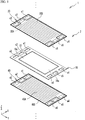
- FIG. 1 is an exploded perspective view of a unit cell 2 of a fuel cell 1.
- the fuel cell 1 is configured by stacking unit cells 2.
- FIG. 1 illustrates only one unit cell 2, and omits other unit cells.
- the unit cell 2 is stacked with other unit cells in the Z direction illustrated in FIG. 1 .
- the unit cell 2 has a substantially rectangular shape.
- the longitudinal direction and the short direction of the unit cell 2 correspond to the Y direction and the X direction illustrated in FIG. 1 , respectively.
- the fuel cell 1 is a polymer electrolyte fuel cell that generates electric power with a fuel gas (for example, hydrogen) and an oxidant gas (for example, oxygen) as reactant gases.
- the unit cell 2 includes: a membrane electrode gas diffusion layer assembly 10 (hereinafter referred to as MEGA (Membrane Electrode Gas diffusion layer Assembly)); a support frame 18 supporting the MEGA 10; a cathode separator 20 and an anode separator 40 (hereinafter referred to as separators) sandwiching the MEGA 10.
- the MEGA 10 has a cathode gas diffusion layer 16c and an anode gas diffusion layer 16a (hereinafter referred to as diffusion layers).
- the support frame 18 has a substantially frame shape, and its inner peripheral side is joined to a peripheral region of the MEGA 10.
- Holes c1 to c3 are formed along one of two short sides of the separator 20, and holes c4 to c6 are formed along the other side.
- holes s1 to s3 are formed along one side of two short sides of the support frame 18, and holes s4 to s6 are formed along the other side.
- holes a1 to a3 are formed along one side of two short sides of the separator 40, and holes a4 to a6 are formed along the other side.
- the holes c1, s1, and a1 communicate with one another to define a cathode inlet manifold.
- the holes c2, s2, and a2 define a coolant inlet manifold.
- the holes c3, s3, and a3 define an anode outlet manifold.
- the holes c4, s4, and a4 define an anode inlet manifold.
- the holes c5, s5, and a5 define a coolant outlet manifold.
- the holes c6, s6, and a6 define a cathode outlet manifold.
- liquid cooling water is used as a coolant.
- a surface of the separator 40 facing the MEGA 10 is formed with anode flow channels 40A (hereinafter referred to as flow channels) which communicate the anode inlet manifold with the anode outlet manifold and along which the fuel gas flows.
- the surface of the separator 20 facing the MEGA 10 is formed with cathode flow channels 20A (hereinafter referred to as flow channels) which communicate the cathode inlet manifold with the cathode outlet manifold and along which the oxidant gas flows.
- the surface of the separator 40 opposite to the flow channels 40A and the surface of the separator 20 opposite to the flow channels 20A are respectively formed with coolant flow channels 20B and 40B (hereinafter referred to as flow channels) which communicate the coolant inlet manifold with the coolant outlet manifold and along which the coolant flows.
- the flow channels 20A and 20B extend in the longitudinal direction of the separator 20 (Y direction).
- the flow channels 40A and 40B extend in the longitudinal direction of the separator 40 (Y direction).
- FIG. 2A is a partially cross-sectional view of the fuel cell 1 where the unit cells 2 are stacked.
- FIG. 2A illustrates only one unit cell 2, and omits the other unit cells.
- FIG. 2A illustrates a cross section orthogonal to the Y direction.
- the MEGA 10 includes the diffusion layers 16a and 16c, and a membrane electrode assembly (hereinafter referred to as MEA (Membrane Electrode Assembly)) 11.
- the MEA 11 includes an electrolyte membrane 12, and an anode catalyst layer 14a and a cathode catalyst layer 14c (hereinafter referred to as catalyst layers) formed on one surface and the other surface of the electrolyte membrane 12, respectively.
- the electrolyte membrane 12 is a solid polymer thin film, such as a fluorine-based ion exchange membrane, with high proton conductivity in a wet state.
- the catalyst layers 14a and 14c are made by coating a catalyst ink containing a carbon support carrying platinum (Pt) or the like and an ionomer having proton conductivity on the electrolyte membrane 12.
- the diffusion layers 16a and 16c are made of a material having gas permeability and conductivity, for example, a porous fiber base material such as carbon fiber or graphite fiber. The diffusion layers 16a and 16c are joined to the catalyst layers 14a and 14c, respectively.
- the separator 20 includes: a metal plate 20c; an electro-conductive resin layer 20a (hereinafter, simply referred to as resin layer) formed on the diffusion layer 16c side of the metal plate 20c; and an electro-conductive resin layer 20b (hereinafter simply referred to as a resin layer) formed on the opposite side to the diffusion layer 16c of the metal plate 20c.
- a material of the metal plate 20c is not particularly limited, but can be stainless steel, titanium, aluminum, iron, copper, or the like.
- the resin layers 20a and 20b are made by dispersing conductive particles in a resin binder.
- the conductive particles can be appropriately selected from, for example, carbon, metal particles having conductivity such as stainless steel, titanium, and gold, and combination thereof.
- the resin binder can be appropriately selected from thermosetting resins such as epoxy and phenol, thermoplastic resins such as polypropylene, polyethylene, polyethylene naphthalate, and combination thereof. At least one of the resin layers 20a and 20b may further contain a hardening accelerator or a release agent such as fluorine.
- the metal plate 20c is covered with such resin layers 20a and 20b. This ensures the entire conductivity of the separator 20 and suppresses a decrease in corrosion resistance of the metal plate 20c. Also, the use of the metal plate 20c ensures airtightness between the oxidant gas flowing on one surface of the separator 20 and the coolant flowing on the other surface.
- the separator 40 includes: a metal plate 40c; an electro-conductive resin layer 40a (hereinafter, simply referred to as resin layer) formed on the diffusion layer 16a side of the metal plate 40c; and an electro-conductive resin layer 40b (hereinafter, simply referred to as a resin layer) formed on the opposite side to the diffusion layer 16a of the metal plate 40c.
- the separator 20 will be described below in detail. A detailed description of the separator 40 will be omitted, since the separator 40 is substantially the same as the separator 20.
- the flow channels 20A, 20B, 40A, and 40B have a wavy shape in a cross-sectional view in the Y direction. Also, the resin layers 20a, 20b, 40a, and 40b and the metal plates 20c and 40c have a wavy shape in cross section.
- the flow channels 20A and 20B are defined by a convex portion 21, a side portion 23, a convex portion 25, a side portion 27, and a convex portion 21... continuously repeated in the X direction, that is, in the direction in which the flow channels 20A and 20B are arranged.
- the convex portion 21 protrudes to the diffusion layer 16c so as to contact the diffusion layer 16c.
- the convex portion 25 does not contact the diffusion layer 16c and protrudes to the side opposite to the diffusion layer 16c.
- the side portion 23 is continuous and inclined between the convex portion 21 and the convex portion 25 away from the convex portion 21 in the +X direction.
- the side portion 27 is continuous and inclined between the convex portion 25 and the convex portion 21 away from the convex portion 25 in the +X direction.
- a space surrounded by the side portion 23, the convex portion 25, and the side portion 27 is defined as the flow channel 20A of the separator 20 on the diffusion layer 16c side. Further, the convex portion 25 contact an anode separator of another unit cell not illustrated adjacent to the upper side of the unit cell 2 illustrated in FIG. 2A . On the anode separator side not illustrated, a space surrounded by the convex portion 21 and the side portions 23 and 27 is defined as the flow channel 20B of the separator 20. In this way, the flow channels 20A and 20B are integrally formed respectively on the side and the other side of the separator 20.
- the flow channels 20A and 20B are an example of flow channels formed by pressing the metal plate 20c and the resin layers 20a and 20b.
- the flow channels 40A and 40B are defined by a convex portion 41, a side portion 43, a convex portion 45, a side portion 47, and a convex portion 41... continuously repeated in the X direction.
- the convex portion 41 protrudes to the diffusion layer 16a so as to contact the diffusion layer 16a.
- the convex portion 45 does not contact the diffusion layer 16a and protrudes to the side opposite to the diffusion layer 16a.
- the side portion 43 is continuous and inclined between the convex portion 41 and the convex portion 45 away from the convex portion 41 in the +X direction.
- the side portion 47 is continuous and inclined between the convex portion 45 and the convex portion 41 away from the convex portion 45 in the +X direction.
- a space surrounded by the side portion 43, the convex portion 45, and the side portion 47 is defined as the flow channel 40A of the separator 40 on the diffusion layer 16a side. Further, the convex portion 45 contact a cathode separator of another unit cell not illustrated adjacent to the lower side of the unit cell 2 illustrated in FIG. 2 . On the cathode separator side not illustrated, a space surrounded by the convex portion 41 and the side portions 43 and 47 is defined as the flow channel 40B of the separator 40. In this way, the flow channels 40A and 40B are integrally formed respectively on the side and the other side of the separator 40.
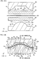
- FIG. 2B is a partially enlarged view of the separator 20.
- the metal plate 20c includes a surface 20c1 and a surface 20c2 opposite thereto.
- the surfaces 20c1 and 20c2 are respectively coated with the resin layers 20a and 20b.
- the separator 20 includes curved portions 22, 24, 26, and 28 without reference numerals in FIG. 2A .
- the curved portion 22 is curved between the convex portion 21 and the side portion 23.
- the curved portion 24 is curved between the side portion 23 and the convex portion 25.
- the curved portion 26 is curved between the convex portion 25 and the side portion 27.
- the curved portion 28 is curved between the side portion 27 and the convex portion 21.
- the entire thickness of the separator 20 is substantially uniform at any position.
- the convex portions 21 and 25 are substantially parallel to the X direction and each has a substantially linear shape.
- the side portion 23 is inclined between the +X direction and the +Z direction from the convex portion 21 in the +X direction and has a substantially linear shape.
- the side portion 27 is inclined between the +X direction and the -Z direction from the convex portion 25 in the +X direction and has a substantially linear shape.
- the convex portion 21 includes a convex surface 21a and a concave surface 21b.
- the convex portion 21a is the outer surface of the resin layer 20a
- the concave surface 21b is the outer surface of the resin layer 20b.
- the side portion 23 includes side surfaces 23a and 23b.
- the side surface 23a is the outer surface of the resin layer 20a
- the side surface 23b is the outer surface of the resin layer 20b.
- the convex portion 25 includes a concave surface 25a and a convex surface 25b.
- the concave surface 25a is the outer surface of the resin layer 20a
- the convex surface 25b is the outer surface of the resin layer 20b.
- the side portion 27 includes side surfaces 27a and 27b.
- the side surface 27a is the outer surface of the resin layer 20a, and the side surface 27b is the outer surface of the resin layer 20b.
- the convex portion 21 also includes a convex portion 21c, which is a region of the metal plate 20c.
- the curved portion 22 includes a curved region 22c, which is a region of the metal plate 20c.
- the side portion 23 also includes a side region 23c, which is a region of the metal plate 20c.
- the curved portion 24 includes a curved region 24c, which is a region of the metal plate 20c.
- the convex portion 25 also includes a convex region 25c, which is a region of the metal plate 20c.
- the curved portion 26 includes a curved region 26c, which is a region of the metal plate 20c.
- the side portion 27 also includes a side region 27c, which is a region of the metal plate 20c.
- the curved portion 28 includes a curved region 28c, which is a region of the metal plate 20c.
- the convex surfaces 21a and 25b and the concave surfaces 21b and 25a are substantially parallel to the X direction.
- the side surfaces 23a and 23b are substantially parallel to each other.
- the side surfaces 27a and 27b are substantially parallel to each other.
- the side surfaces 23a and 23b and the side surfaces 27a and 27b are substantially symmetrical with respect to a plane that is perpendicular to the X axis and passes through the convex portion 25.
- the convex surfaces 21a and 25b and the concave surfaces 21b and 25a are flat.
- the convex region 21c positioned between the convex surface 21a and the concave surface 21b is curved so as to slightly protrude in the -Z direction, in other words, to the surface 20c1.
- the convex region 25c positioned between the concave surface 25a and the convex surface 25b is curved so as to slightly protrude in the +Z direction, in other words, to the surface 20c2.
- the side surfaces 23a, 23b, 27a, and 27b are also flat, but not limited thereto.
- a recess portion 25d is formed substantially at the center of the concave surface 25a in the X direction.
- a recess portion 21d is formed substantially in the center of the concave surface 21b in the X direction.
- the convex region 25c is curved so as to slightly protrude to the convex surface 25b and away from the recess portion 25d.
- the convex region 21c is also curved so as to slightly protrude to the convex surface 21a and away from the recess portion 21d.
- the convex region 21c is close to the concave surface 21b
- the convex region 25c is close to the concave surface 25a as compared with the case illustrated in FIG. 2B .
- the curved regions 22c, 24c, 26c, and 28c and the like are greatly curved and each curvature thereof is increased as compared with the case illustrated in FIG. 2B .
- the convex regions 21c and 25c are curved so as to slightly protrude to the convex surfaces 21a and 25b, respectively. This suppresses an increase in each curvature in the curved regions 22c, 24c, 26c, and 28c.
- the separator 20 is formed by hot pressing described above, and a flat metal plate is compressed with dies and deformed in the hot pressing, so that the metal plate 20c illustrated in FIG. 2B is also formed. Therefore, a partial increase in curvature illustrated in FIG. 6 might reduce the stiffness of a part of the metal plate 20c. However, a partial increase in curvature is suppressed in the present embodiment, thereby suppressing a decrease in stiffness of the metal plate 20c.
- this eliminates the necessity of making the flow channels 20A and 20B shallow in order to suppress an increase in each curvature of the curved regions 22c, 24c, 26c, and 28c. This suppresses an increase in pressure loss of the oxidant gas and the coolant respectively flowing along the flow channels 20A and 20B. This also suppresses a decrease in power generation efficiency of the fuel cell 1 and suppresses a decrease in cooling efficiency. Further, this eliminates the necessity of widening the flow channels 20A and 20B while securing the depths thereof in order to suppress an increase in each curvature of the curved regions 22c, 24c, 26c, and 28c. It is therefore possible to sandwich the MEGA 10 at a suitable interval.
- the convex surface 25b is flat as described above, thereby ensuring the contact area between the convex surface 25b of the separator 20 and the separator of the other unit cell adjacent to the separator 20. This suppresses an increase in electric resistance between the separator 20 and the separator of the other adjacent unit cell.
- the convex surface 21a is flat. This can ensure the contact area between the convex surface 21a of the separator 20 and the diffusion layer 16c. It is therefore possible to stably hold the MEGA 10 between the separators 20 and 40. This can hold the MEA 11 with sufficient sandwiching force. It is thus possible to suppress a decrease in strength of the MEA 11 due to repetition of swell, expansion, and contraction in a region thereof on which insufficient sandwiching force exerts.
- the ratio of the thickness of the metal plate 20c to the total thickness of the resin layers 20a and 20b and the metal plate 20c is preferably set to 50% or less. As the thickness of the metal plate 20c is smaller relative to the total thickness of the resin layers 20a and 20b and the metal plate 20c, an increase in each curvature of, for example, the curved region 22c and the curved region 24c can be further suppressed.
- FIG. 3 is a flowchart illustrating the method of manufacturing the separator 20.
- FIGs. 4A to 4C are explanatory views of dies 70 and 80 used in manufacturing the separator 20.
- FIG. 4A illustrates external views of the dies 70 and 80
- FIGs. 4B and 4C are partially enlarged views of the dies 80 and 70, respectively.
- FIGs. 5A and 5B are explanatory views of the method of manufacturing the separator 20.
- the separator 20 is manufactured by hot pressing.
- FIGs. 4B , 5A, and 5B illustrate partially enlarged views of the dies in cross section.
- the dies 70 and 80 are prepared (step S10).
- grooves 70A extending in the Y direction and having a wavy shape in the X direction are formed on the surface of the die 70 opposite to the die 80.
- grooves 80A extending in the Y direction and having a wavy shape in the X direction are formed on the surface of the die 80 opposite to the die 70.
- Recessed portions 70c1 to 70c3 and recessed portions 70c4 to 70c6 are formed on the surface of the die 70 opposite to the die 80 so as to sandwich the grooves 70A in the Y direction.
- Recessed portions 80c1 to 80c3 and recessed portions 80c4 to 80c6 are formed on the surface of the die 80 opposite to the die 70 so as to sandwich the grooves 80A in the Y direction.
- the grooves 70A and 80A are portions for forming the flow channels 20A and 20B of the separator 20.
- the recessed portions 70c1 to 70c6 are respectively opposite to the recessed portions 80c1 to 80c6, and they are portions for forming the holes c1 to c6.
- the groove 80A is defined by a convex surface 81, a side surface 83, a concave surface 85, a side surface 87, a convex surface 81... formed in this order in the X direction.
- the concave surface 85 recedes from the die 70 with respect to the convex surface 81, and the convex surface 81 protrudes to the die 70 from the concave surface 85.
- a part of the convex surface 81 and the concave surface 85 are substantially parallel to the X direction and are formed into be flat.
- the side surface 83 is inclined and positioned between the convex surface 81 and the concave face 85 positioned in the +X direction from the convex surface 81, and connects the both surfaces.
- the side surface 87 is inclined and positioned between the concave surface 85 and the convex surface 81 positioned in the +X direction from the concave surface 85, and connects both surfaces.
- a protruding portion 81d partially protruding from the convex surface 81 to the die 70 is formed to extend in the Y direction, that is, the direction in which the groove 80A extends.
- the protruding portion 81d is formed on the entire convex surface 81.
- the convex surface 81 has an end portion 811 and an end portion 812 positioned in the +X direction from the end portion 811.
- the end portion 811 is a boundary portion between the side surface 87 and the convex surface 81
- the end portion 812 is a boundary portion between the convex surface 81 and the side surface 83.
- the protruding portion 81d is not particularly limited, but is provided at substantially the center in the X direction of the convex surface 81.
- the protruding height of the protruding portion 81d from the convex surface 81 is not particularly limited, but is constant in the Y direction.
- the protruding portion 81d has a taper shape such that a top surface is flat and both side surfaces are inclined and closer to each other as being farther away from the convex surface 81 in the -Z direction in a cross-sectional view perpendicular to the Y direction.
- the shape of the protruding portion 81d is not particularly limited to this. As illustrated in FIG. 5A which will be described later, the protruding height of the protruding portion 81d from the convex surface 81 is the same as the depth of the recess portion 21d illustrated in FIG. 2B .
- the groove 70A is defined by a concave surface 71, a side surface 73, a convex surface 75, a side surface 77, a concave surface 71...formed in this order in the X direction.
- the convex surface 75 protrudes to the die 80 with respect to the concave surface 71, and the concave surface 71 recedes from the die 80 with respect to the convex surface 75.
- the concave surface 71 and a part of the convex surface 75 are substantially parallel to the X direction and are flat.
- the side surface 73 is inclined between the concave surface 71 and the convex surface 75 positioned in the + X direction from the concave surface 71, and connects both surfaces.
- the side surface 77 is positioned between the convex surface 75 and the concave surface 71 positioned in the + X direction from the convex surface 75, and connects both surfaces.
- a protruding portion 75d partially protruding from the convex surface 75 to the die 80 is formed to extend in the Y direction, that is, the direction in which the groove 70A extends.
- the protruding portion 75d is formed over the entire convex surface 75.
- the convex surface 75 includes an end portion 751 and an end portion 752 positioned in the + X direction from the end portion 751.
- the end portion 751 is a boundary portion between the side surface 73 and the convex surface 75
- the end portion 752 is a boundary portion between the convex surface 75 and the side surface 77.
- the protruding portion 75d is not particularly limited, but is provided at substantially the center in the X direction of the convex surface 75.
- the protruding height of the protruding portion 75d from the convex surface 75 is not particularly limited, but is constant in the Y direction.
- the protruding portion 75d has a taper shape such that a top surface is flat and both side surfaces are inclined and closer to each other as being farther away from the convex surface 75 in the +Z direction in a cross-sectional view perpendicular to the Y direction.
- the shape of the protruding portion 75d is not particularly limited to this. As illustrated in FIG. 5A which will be described later, the protruding height of the protruding portion 75d is the same as the protruding height of the protruding portion 81d and as the depth of the recess portion 25d illustrated in FIG. 2B .
- the concave surface 71, the side surface 73, the convex surface 75, and the side surface 77 are respectively complementary to the convex surface 81, the side surface 83, the concave surface 85, and the side surface 87.
- the dies 70 and 80 are set beforehand such that the concave surface 71, the side surface 73, the convex surface 75, and the side surface 77 respectively face the convex surface 81, the side surface 83, the concave surface 85, and the side surface 87.
- the protruding portion 75d of the die 70 partially protrudes from the convex surface 75 to the concave surface 85 of the die 80
- the protruding portion 81d of the die 80 partially protrudes from the convex surface 81 to the concave surface 71 of the die 70.
- the convex surface 75 includes the protruding portion 75d as an example of a portion provided between the end portions 751 and 752 of the convex surface 75 in the direction in which the convex surface 75 and the concave surface 71 are arranged, protruding to the concave surface 85, and having a protruding height higher than each height of the end portions 751 and 752.
- the convex surface 81 includes the protruding portion 81d as an example of a portion provided between the end portions 811 and 812 of the convex surface 81 in the direction in which the convex surface 81 and the concave surface 85 are arranged, protruding to the concave surface 71, and having a protruding height higher than each height of the end portions 811 and 812.
- a round corner portion is provided at any one of a position between the side surface 23a and the concave surface 25a, a position between the concave surface 25a and the side surface 27a, a position between the concave surface 21b and the side surface 23b, and a position between the concave surface 21b and the side surface 27b, and the round corner portion is for smoothly connecting these surfaces.
- each of the dies 70 and 80 is provided with a round corner portion having a curved surface at a corresponding position thereof. For example, when a round corner portion is provided between the side surface 73 and the convex surface 75, the round corner portion is not included in the convex surface 75 but in the side surface 73.
- the end portion 751 of the convex surface 75 is not included in the round corner portion, but corresponds to the boundary portion between the flat convex surface 75 and the curved round corner portion.
- the round corner portion is provided between the convex surface 75 and the side surface 77, between the side surface 87 and the convex surface 81, or between the side surface 83 and the convex surface 81. That is, the end portions 752, 811, and 812 are not included in the round corner portion.
- Each angle of the above-described surfaces is set to correspond to each outer surface of the above-described separator 20 as follows. Specifically, each of an exterior angle of the die 70 between the concave surface 71 and the side surface 73, an exterior angle of the die 70 between the side surface 77 and the concave surface 71, an exterior angle of the die 80 between the side surface 83 and the concave surface 85, and an exterior angle of the die 80 between the concave surface 85 and the side surface 87 are set to be 90 degrees or more but less than 180 degrees.
- Each of an exterior angle of the die 70 between the side surface 73 and the convex surface 75, an exterior angle of the die 70 between the convex surface 75 and the side surface 77, exterior angle of the die 80 between the convex surface 81 and the side surface 83, an exterior angle of the die 80 between the side face 87 and the convex face 81 is set to be greater than 180 degrees but not more than 270 degrees.
- a metal plate 20c' and resin sheets 20a' and 20b' are prepared (step S20).
- the metal plate 20c' corresponds to the metal plate 20c of the completed separator 20.
- the resin sheets 20a' and 20b' respectively correspond to the resin layers 20a and 20b of the completed separator 20.
- the resin sheets 20a' and 20b' are heated to a temperature lower than the curing temperature of the thermosetting resin to be brought into a semi-cured state and to each have a sheet shape.
- step S30 the resin sheets 20a' and 20b' and the metal plate 20c' are heated and pressed by the dies 70 and 80, in a state where the resin sheet 20a' is set closer to the die 70 in one side of the metal plate 20c' and the resin sheet 20b' is set close to the die 80 in the other side of the metal plate 20c' as illustrated in FIGs. 5A and 5B (step S30).
- reference numerals are omitted in FIG. 5B .
- the convex surface 75 presses the resin sheet 20a' to the die 80
- the convex surface 81 presses the resin sheet 20b' to the die 70.
- the resin sheets 20a' and 20b' and the metal plate 20c' are integrally curved along the shapes of the dies 70 and 80.
- the resin sheets 20a' and 20b' in the semi-cured state described above are softer than the metal plate 20c'.
- the resin sheets 20a' and 20b' are respectively deformed along the shapes of the dies 70 and 80, and the deformation amount of the metal plate 20c' is smaller than that of the resin sheets 20a' and 20b'.
- the metal plate 20c' is curved to protrude to the concave surface 85.
- the metal plate 20c' is curved to protrude to the concave surface 71.
- the resin sheets 20a' and 20b' are deformed and compressed to form the resin layers 20a and 20b illustrated in FIG. 5B . Therefore, the separator 20 having the metal plate 20c with the curvature suppressed from partially increasing is manufactured.
- the distance between the convex surface 75 and the concave surface 85 in the Z direction is adjusted so as to be each thickness of the convex portions 21 and 25 illustrated in FIG. 2 .
- the heating temperature of the resin sheets 20a' and 20b' is adjusted so as to each have a desired shape before the resin sheets 20a' and 20b' are completely thermally cured.
- the resin sheet 20a' is compressed between the die 70 and the metal plate 20c.
- the resin layers 20a and 20b and the metal plate 20c are cooled and integrated.
- the deformation amount of the metal plate 20c' can be adjusted by changing each viscosity of the resin sheets 20a' and 20b'.
- the relatively low viscosity of the resin sheets 20a' and 20b' causes a small deformation amount of the metal plate 20c'.
- the relatively high viscosity of the resin sheets 20a' and 20b' causes a large deformation amount of the metal plate 20c'.
- Step S40 holes are formed at positions corresponding to the recessed portions 70c1 to 70c6 and 80c1 to 80c6 of the integrated resin layers 20a and 20b and the metal plate 20c so as to form the holes c1 to c6 illustrated in FIG. 1 (Step S40).
- the separator 20 is manufactured.
- the separator 40 is also manufactured by the same method.
- the flow channels 20A and 20B can be formed by hot pressing the resin sheets 20a' and 20b' and the flat plate-shaped metal plate 20c' once.
- the manufacturing method is simplified.
- undercoat paint may be applied beforehand on both surfaces of the metal plate 20c' before the hot pressing. This can ensure the stiffness of the completed separator 20.
- the surface portions of the resin sheets 20a' and 20b' may be previously joined to the metal plate 20c' before the hot pressing. This facilitates handling the metal plate 20c' and the resin sheets 20a' and 20b' in the hot pressing.
- the concave surfaces 71 and 85 are flat, so that the convex surfaces 21a and 25b of the separator 20 are also flat. This can ensure the contact area between the separator 20 and the separator of another unit cell adjacent to the separator 20, and ensure the contact area between the separator 20 and the diffusion layer 16c, as described above.
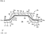
- FIG. 6 is a partially enlarged sectional view of the separator 20x of the comparative example.
- the separator 20x is manufactured by the same manufacturing method as the separator 20 according to the present embodiment, but it is manufactured by two dies not provided with the protruding portions 75d and 81d. Therefore, unlike the separator 20, the separator 20x is not formed with the recess portions 21d and 25d.
- a metal plate 20cx of the separator 20x includes a convex region 21cx, a curved region 22cx, a side region 23cx, a curved region 24cx, a convex region 25cx, a curved region 26cx, a side region 27cx, and a curved region 28cx, but differs from the metal plate 20c of the separator 20 in shape. Specifically, as compared with the separator 20 in the present embodiment illustrated in FIG. 2B , the convex region 21cx is positioned close to the concave surface 21b, and the convex region 25cx is positioned close to the concave surface 25a.
- the curvatures at the curved regions 22cx, 24cx, 26cx, and 28cx increases.
- the curvature of the metal plate 20cx partially increases. Since the dies 70 and 80 respectively provided with the protruding portions 75d and 81d are used in the present embodiment, the convex region 21c and the convex region 25c of the metal plate 20c are respectively suppressed from being too close to the concave surfaces 21b and 25a.
- the convex regions 21c and 25c are suitably curved to suppress the curvature of the metal plate 20c from partially increasing.
- the protruding portions 75d and 81d are respectively formed in the dies 70 and 80, but such a protruding portion may be formed only in one thereof.
- the protruding portion 75d is provided in the die 70 and the protruding portion 81d is not provided in the die 80, the convex region 25c of the metal plate 20c is curved to protrude to the die 80 by the protruding portion 75d, thereby suppressing an increase in each curvature of the curved regions 24c and 26c adjacent to the convex region 25c.
- the position of the protruding portion 75d is not limited to the center of the convex surface 75 in the X direction.
- the size of the protruding portion 75d is not limited to the above one, and may be appropriately set in light of a limit value of curvature of the metal plate 20c and the like.
- the shape of the protruding portion 75d is not limited to the above one, and for example, the top surface thereof may protrude to the concave surface 85 in a curved shape, and at least one of both side surfaces of the protruding portion 75d may be perpendicular to the convex surface 75.
- the position, the size, and the shape of the protruding portion 81d are not limited to the above examples.
- the protruding portion 75d is formed on each of the convex surfaces 75 of the die 70, and the protruding portion 75d may be formed on at least one of the convex surfaces 75.
- the protruding portion 81d provided in the die 80.
- thermosetting resin as an example of the resin binders of the resin sheets 20a' and 20b'.
- the resin sheet is heated to a certain temperature to be brought into a semi-cured state before the hot press, and the resin sheet is pressed and heated to a temperature at which the viscosity does not decrease too much, and then the resin sheet may be cooled.
- steps S10 and S20 the order of preparing the die 70, the die 80, the metal plate 20c', the resin sheet 20a', and the resin sheet 20b'is not limited.
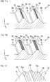
- FIG. 7A is a partially cross-sectional perspective view of a die 70a according to the first variation.
- a protruding portion 75da as an example of the above-described portion is formed on a convex surface 75a of the die 70a.
- the protruding portion 75da is formed into a conical shape on the convex surface 75a.
- the protruding portions 75da are provided in a direction in which the groove 70A extends, and the protruding height of the entire protruding portions 75da from the convex surface 75a is not constant in the Y direction.
- Such dies 70a and 80 can suppress the curvature of the metal plate 20c from partially increasing.
- a die provided with the protruding portions 75da may be used, like the die 70a.
- the shape of the protruding portion 75da is not limited to a conical one, and may be, for example, a pyramidal shape, a columnar shape, or a prismatic shape.
- the protruding portions 75da may be provided so as to contact with each other in the Y direction, or may be provided at predetermined intervals. In the case where the protruding portions are provided at predetermined intervals in the Y direction, the protruding portion are preferably provided at certain intervals such that the shape of the convex region 25c of the metal plate 20c is constant regardless of the position in the Y direction in the hot press.
- the number and the size of the protruding portions 75da are not particularly limited.
- FIG. 7B is a partially cross-sectional perspective view of a die 70b according to the second variation.
- FIG. 7C is a partially enlarged view of FIG. 7B .
- protruding portions 75ds are formed as an example of the above-described portion.
- the two protruding portions 75ds are provided so as to extend substantially parallel to the protruding portion 75d and to sandwich the protruding portion 75d. That is, the protruding portions 75d and 75ds provided on the single convex surface 75b are arranged in such a direction that the concave surface 71 and the convex surface 75b are arranged.
- the protruding height of the protruding portion 75ds from the convex surface 75b is lower than that of the protruding portion 75d.
- the interval between one of the two protruding portions 75ds and the protruding portion 75d in the X direction is set to be the same as the interval between the other of the two protruding portions 75ds and the protruding portion 75d in the X direction.
- the protruding portion 75ds can finely process the height position in the Z direction around the curved regions 24c and 26c in the convex region 25c of the metal plate 20c, thereby forming the metal plate 20c' in a desired shape and suppressing the curvature of the metal plate 20c from partially increasing.
- Such dies 70b and 80 can suppress the curvature of the metal plate 20c from partially increasing.
- a die provided with the protruding portions 75d and 75ds may be used like the die 70b, or a die provided with the protruding portions 75da may be used like the die 70a.
- the protruding portion 75ds may be substantially the same as the protruding portion 75d in protruding height from the convex surface 75b, or may be higher than the protruding portion 75d. In the above variation, a total of three protruding portions including the protruding portion 75d and the two protruding portions 75ds are provided on the single convex surface 75b, but the number of the protruding portions is not limited. The position of the protruding portion 75ds is not limited to the above. Further, the interval between the protruding portions in the X direction may not be even.
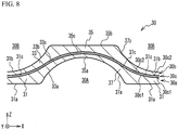
- FIG. 8 is a partially enlarged sectional view of the separator 30 manufactured by the dies 70c and 80c according to the third variation.
- a metal plate 30c has a surface 30c1 and a surface 30c2 opposite to the surface 30c1.
- the surfaces 30c1 and 30c2 are respectively covered with resin layers 30a and 30b.
- the materials of the resin layers 30a and 30b are the same as those of the resin layers 20a and 20b described above.
- Flow channels 30A and 30B extend in the Y direction.
- the flow channels 30A and 30B are defined by a convex portion 31, a side portion 33, a convex portion 35, a side portion 37, a convex portion 31,..that are repeated continuously in the X direction, that is, the direction in which the flow channels 30A and 30B are arranged.
- the convex portion 31 contacts the diffusion layer 16c, and the convex portion 35 contacts a separator of the adjacent other unit cell.
- the side portion 33 is inclined and continuous between the convex portion 31 and the convex portion 35 positioned in the +X direction from the convex portion 31.
- the side portion 37 is inclined and continuous between the convex portion 35 and the convex portion 31 positioned in the +X direction from the convex portion 35.
- the convex portion 31 includes a convex surface 31a and a concave surface 31b.
- the convex portion 31a is the outer surface of the resin layer 30a
- the concave surface 31b is the outer surface of the resin layer 30b.
- the side portion 33 includes side surfaces 33a and 33b.
- the side surface 33a is the outer surface of the resin layer 30a
- the side surface 33b is the outer surface of the resin layer 30b.
- the convex portion 35 includes a concave surface 35a and a convex surface 35b.
- the concave surface 35a is the outer surface of the resin layer 30a
- the convex surface 35b is the outer surface of the resin layer 30b.
- the side portion 37 includes side surfaces 37a and 37b.
- the side surface 37a is the outer surface of the resin layer 30a, and the side surface 37b is the outer surface of the resin layer 30b.
- the convex portion 31 also includes a convex portion 31c, which is a region of the metal plate 20c.
- the side portion 33 also includes a side region 33c, which is a region of the metal plate 20c.
- the convex portion 35 also includes a convex region 35c, which is a region of the metal plate 20c.
- the side portion 37 also includes a side region 37c, which is a region of the metal plate 20c.
- the convex surfaces 31a and 35b are substantially parallel to the X direction and are flat.
- the concave surface 35a is curved such that the flow channel 30A is made deeper as being closer to the center in the X direction within the range of the convex portion 35. That is, the thickness of the convex portion 35 corresponding to the distance between the concave surface 35a and the convex surface 35b in the Z direction is made gradually thicker as being farther away from the center of the convex portion 35 in the X direction.
- the concave surface 31b is curved such that the flow channel 30B is made deeper as being closer to the center in the X direction within the range of the convex portion 31.
- the thickness of the convex portion 31 corresponding to the distance between the convex surface 31a and the concave surface 31b in the Z direction is made gradually thicker as being farther away from the center of the convex portion 31 in the X direction.
- the side surfaces 33a and 37a are continuously curved with the concave surface 35a positioned therebetween.
- the side surfaces 33b and 37b are continuously curved with the concave surface 31b positioned therebetween.
- FIGs. 9A and 9B are partially enlarged views of dies 80c and 70c according to the third variation.
- FIGs. 10A and 10B are explanatory views of a method of manufacturing the separator 30 by use of the dies 80c and 70c according to the third variation.
- a groove 80Ac is defined by a convex surface 81c, a side surface 83c, a concave surface 85c, a side surface 87c, a convex surface 81c... formed in this order in the X direction.
- the convex surface 81c, and the side surfaces 83c and 87c positioned on both sides of the convex surface 81c, are continuously curved.
- the convex surface 81c protrudes most to a concave surface 71c of the die 70c described later.
- a groove 70Ac is defined by a concave surface 71c, a side surface 73c, a convex surface 75c, a side surface 77c, a concave surface 71c... formed in this order in the X direction.
- the convex surface 75c, and the side surfaces 73c and 77c positioned on both sides of the convex surface 75c are continuously curved.
- the convex surface 75c protrudes most to the concave surface 85c of the die 80c.
- the concave surfaces 71c and 85c are substantially parallel to the X direction and flat.
- the convex surface 81c includes an end portion 811c and an end portion 812c positioned in the + X direction from the end portion 811c.
- the end portion 811c is a boundary portion between the side surface 87c and the convex surface 81c.
- the end portion 812c is a boundary portion between the convex surface 81c and the side surface 83c.
- the convex surface 75c includes an end portion 751c and an end portion 752c positioned in the + X direction from the end portion 751c.
- the end portion 751c is a boundary portion between the side surface 73c and the convex surface 75c.
- the end portion 752c is a boundary portion between the convex surface 75c and the side surface 77c.
- the convex surface 81c and the side surfaces 83c and 87c positioned on both sides of the convex surface 81c are continuously curved as described above.
- the end portion 811c is formed at an arbitrary position on a continuously curved surface.
- the boundary portion in which the curvature changes may be the end portion 811c. The same applies to the end portions 812c, 751c, and 752c.
- the convex surfaces 75c and 81c respectively protrude to the concave surfaces 85c and 71c so as to be curved, and the protruding height at substantially the center in the X direction is the highest.
- the convex surface 75c is an example of a portion provided between the end portions 751c and 752c of the convex surface 75c in the direction in which the convex surface 75c and the concave surface 71c are arranged, protruding to the concave surface 85c, and having a protruding height higher than each height of the end portions 751c and 752c of the convex surface 75c.
- the convex surface 81c is an example of a portion provided between the end portions 811c and 812c of the convex surface 81c in the direction in which the convex surface 81c and the concave surface 85c are arranged, protruding to the concave surface 71c, and having a protruding height higher than each height of the end portions 811c and 812c of the convex surface 81c.
- the convex surface 75c presses the resin sheet 20a' to the die 80c
- the convex surface 81c presses the resin sheet 20b' to the die 70.
- the resin sheets 20a' and 20b' and the metal plate 20c' are integrally curved along the shapes of the dies 70c and 80c.
- the resin sheet 20a' is compressed between the metal plate 20c' and the die 70c
- the resin sheet 20b' is compressed between the metal plate 20c' and the die 80c.
- a gap between the convex surface 75c and the metal plate 20c' in the Z direction is made narrow before a gap between the concave surface 71c and the metal plate 20c' in the Z direction is made narrow, and a part of the resin sheet 20a' is preferentially compressed by the convex surface 75c and the metal plate 20c'.
- the compressed part of the resin sheet 20a' flows to a large gap between the concave surface 71c and the metal plate 20c' in the -X direction from the convex surface 75c through a gap between the side surface 73c and the metal plate 20c', and flows to a large gap between the concave surface 71c and the metal plate 20c' in the +X direction from the convex surface 75c through a gap between the side surface 77c and the metal plate 20c'.
- a gap between the convex surface 81c and the metal plate 20c' in the Z direction is made narrow before a gap between the concave surface 85c and the metal plate 20c' in the Z direction is made narrow, and a part of the resin sheet 20b' is preferentially compressed by the convex surface 81c and the metal plate 20c'.
- a part of the compressed resin sheet 20b' flows to a large gap between the concave surface 85c and the metal plate 20c' in the +X direction through a gap between the side surface 83c and the metal plate 20c', and flows to a large gap between the concave surface 85c and the metal plate 20c' in the -X direction through a gap between the side surface 87c and the metal plate 20c'.
- the metal plate 20c' This causes the metal plate 20c' to be gently curved continuously along the convex surface 81c, the side surface 83c, the concave surface 85c, and the side surface 87c.
- the entire metal plate 20c' is gently curved in this manner, and the convex region 31c, the side region 33c, the convex region 35c, and the side region 37c of the metal plate 30c are continuously curved as illustrated in FIG. 10B .
- This can suppress a partial increase in curvature of the metal plate 30c, and a decrease in stiffness thereof.
- the resin sheets 20a' and 20b' are deformed and compressed to form the resin layers 30a and 30b illustrated in FIG. 10B .
- reference numerals are omitted in FIG. 10B .
- the convex portions 31 and 35 illustrated in FIG. 8 are compressed before the side portions 33 and 37 in the hot pressing, thereby increasing the density of the conductive particles in the convex portions 31 and 35 of the resin layers 30a and 30b.
- one of the convex portions 31 and 35 respectively come into contact with the diffusion layer and another separator of another unit cell, thereby suppressing an increase in electrical resistance at the contacting point.
- the side surfaces 73c, 77c, 83c, and 87c are curved, but at least one of them may be flat. Also, the convex surfaces 75c and 81c are preferably smoothly curved in consideration of a decrease in pressure loss of fluids flowing along the flow channels 30A and 30B, but the present invention is not necessarily limited to this, for example, it may be curved to have a polygonal shape.
- the separator manufactured by the above manufacturing method is not limited to a water-cooled type fuel cell using a liquid as a coolant, and may be adopted in, for example, an air-cooled fuel cell using air as a coolant.
- the step of "preparing" in the above manufacturing method only needs to prepare an object at the time of performing the above manufacturing method. For example, even the case where manufacturing the object is included in "preparing".
- the object may be prepared by any process, such as purchasing the object from others.
Landscapes
- Chemical & Material Sciences (AREA)
- Engineering & Computer Science (AREA)
- Chemical Kinetics & Catalysis (AREA)
- Sustainable Development (AREA)
- Sustainable Energy (AREA)
- Manufacturing & Machinery (AREA)
- Life Sciences & Earth Sciences (AREA)
- Electrochemistry (AREA)
- General Chemical & Material Sciences (AREA)
- Composite Materials (AREA)
- Physics & Mathematics (AREA)
- Mechanical Engineering (AREA)
- Thermal Sciences (AREA)
- Fluid Mechanics (AREA)
- Fuel Cell (AREA)
Abstract
Description
- The present invention relates to a manufacturing method of a separator for a fuel cell.
- There is known a fuel cell including a pair of separators sandwiching a membrane electrode gas diffusion layer assembly. Such a separator is formed with flow channels having a wavy shape in cross section. A reactant gas flows along the flow channels on the membrane electrode gas diffusion layer assembly side. A coolant flows on the side opposite to the flow channels. The membrane electrode gas diffusion layer assembly is sandwiched by the flow channels of the separators. In addition, there is known a separator including a metal plate and electro-conductive resin layers provided on respective surfaces of the metal plate. As for the flow channels, the metal plate and the electro-conductive resin layers are formed to have a wavy shape in cross section (see, for example, Japanese Unexamined Patent Application Publication No.
2003-297383 - The metal plate is formed to have a wavy shape in cross section by pressing. Therefore, a curvature of the metal plate might be partially increased, and the stiffness might be further decreased depending on the depth of the flow channel. In addition, if the depth of the flow channel is formed to be shallow in order to suppress such a decrease in stiffness of the metal plate, the pressure loss of the reactant gas and the coolant flowing along the flow channels may increase. Further, if a width of the flow channel is increased while ensuring the depth thereof in order to suppress the decrease in stiffness of the metal plate as described above, the membrane electrode gas diffusion layer assembly might not be sandwiched at a suitable interval. This might decrease an area of a membrane electrode assembly on which sufficient sandwiching force exerts, so that the membrane electrode assembly might repeatedly swell and expand in the area on which small sandwiching force exerts, and its strength might decrease.
- It is therefore an object of the present invention to provide a manufacturing method of a separator for a fuel cell in which a decrease in stiffness of a metal plate is suppressed without influence on a width and a depth of a flow channel.
- The above object is achieved by a manufacturing method of a separator for a fuel cell, including: preparing a first die including: a first convex surface and a first concave surface; and a first side surface connected between the first convex surface and the first concave surface; preparing a second die including: a second concave surface and a second convex surface respectively facing the first convex surface and the first concave surface; and a second side surface facing the first side surface and connected between the second concave surface and the second convex surface; preparing a metal plate having a flat plate shape, and two electro-conductive resin sheets; and forming a flow channel in the metal plate and the two electro-conductive resin sheets by hot pressing with the first and second dies in a state where one of the electro-conductive resin sheets is set at one side of the metal plate and the other one of the electro-conductive resin sheets is set at the other side of the metal plate, wherein the first convex surface includes a first portion provided between both end portions of the first convex surface in a direction in which the first convex surface and the first concave surface are arranged, protruding to the second concave surface, and having a protruding height higher than each height of the both end portions of the first convex surface.
- In the hot pressing, the first portion of the first convex surface causes a part of the metal plate between the first convex surface and the second concave surface to be curved and to protrude to the second concave surface. Therefore, the part of the metal plate between the first convex surface and the second concave surface and a part of the metal plate between the first and second side surfaces are continuously curved. This suppresses a partial increase in curvature of the metal plate, and a decrease in stiffness of the metal plate.
- The first portion may protrude from a part of the first convex surface to the second concave surface.
- The first portion may be positioned at a center of the first convex surface in the direction in which the first convex surface and the first concave surface are arranged.
- A plurality of the first portions may be provided on the first convex surface, and the first portions are arranged in the direction in which the first convex surface and the first concave surface are arranged.
- The first portion may be curved such that the protruding height is higher than each height of the both end portions.
- The first side surface may be curved continuously to the first portion.
- A center of the first convex surface of the first portion in the direction in which the first convex surface and the first concave surface are arranged may protrude most to the second concave surface.
- The second convex surface may include a second portion provided between both end portions of the second convex surface in a direction in which the second convex surface and the second concave surface are arranged, protruding to the first concave surface, and having a protruding height higher than each height of the both end portions of the second convex surface.
- According to the present invention, it is possible to provide a manufacturing method of a separator for a fuel cell in which a decrease in stiffness of a metal plate is suppressed without influence on a width and a depth of a flow channel.
-
-
FIG. 1 is an exploded perspective view of a unit cell of a fuel cell; -
FIG. 2A is a partially cross-sectional view of the fuel cell where the unit cells are stacked, andFIG. 2B is a partially enlarged sectional view of a separator; -
FIG. 3 is a flowchart illustrating a manufacturing method of a separator; -
FIGs. 4A to 4C are explanatory views of dies used in manufacturing the separator; -
FIGs. 5A and 5B are explanatory views of the separator; -
FIG. 6 is a partially enlarged sectional view of a separator of a comparative example; -
FIG. 7A is a partially cross-sectional perspective view of a die according to the first variation,FIG. 7B is a partially cross-sectional perspective view of a die according to a second variation, andFIG. 7C is a partially enlarged view ofFIG. 7B ; -
FIG. 8 is a partially enlarged sectional view of a separator manufactured by dies according to the third variation; -
FIGs. 9A and 9B are partially enlarged view of the dies according to the third variation; and -
FIGs. 10A and 10B are explanatory views of a method of manufacturing the separator by use of the dies according to the third variation. -
FIG. 1 is an exploded perspective view of aunit cell 2 of afuel cell 1. Thefuel cell 1 is configured bystacking unit cells 2.FIG. 1 illustrates only oneunit cell 2, and omits other unit cells. Theunit cell 2 is stacked with other unit cells in the Z direction illustrated inFIG. 1 . Theunit cell 2 has a substantially rectangular shape. The longitudinal direction and the short direction of theunit cell 2 correspond to the Y direction and the X direction illustrated inFIG. 1 , respectively. - The
fuel cell 1 is a polymer electrolyte fuel cell that generates electric power with a fuel gas (for example, hydrogen) and an oxidant gas (for example, oxygen) as reactant gases. Theunit cell 2 includes: a membrane electrode gas diffusion layer assembly 10 (hereinafter referred to as MEGA (Membrane Electrode Gas diffusion layer Assembly)); asupport frame 18 supporting the MEGA 10; acathode separator 20 and an anode separator 40 (hereinafter referred to as separators) sandwiching the MEGA 10. The MEGA 10 has a cathodegas diffusion layer 16c and an anodegas diffusion layer 16a (hereinafter referred to as diffusion layers). Thesupport frame 18 has a substantially frame shape, and its inner peripheral side is joined to a peripheral region of the MEGA 10. - Holes c1 to c3 are formed along one of two short sides of the
separator 20, and holes c4 to c6 are formed along the other side. Likewise, holes s1 to s3 are formed along one side of two short sides of thesupport frame 18, and holes s4 to s6 are formed along the other side. Likewise, holes a1 to a3 are formed along one side of two short sides of theseparator 40, and holes a4 to a6 are formed along the other side. The holes c1, s1, and a1 communicate with one another to define a cathode inlet manifold. Likewise, the holes c2, s2, and a2 define a coolant inlet manifold. The holes c3, s3, and a3 define an anode outlet manifold. The holes c4, s4, and a4 define an anode inlet manifold. The holes c5, s5, and a5 define a coolant outlet manifold. The holes c6, s6, and a6 define a cathode outlet manifold. In thefuel cell 1 according to the present embodiment, liquid cooling water is used as a coolant. - A surface of the
separator 40 facing theMEGA 10 is formed withanode flow channels 40A (hereinafter referred to as flow channels) which communicate the anode inlet manifold with the anode outlet manifold and along which the fuel gas flows. The surface of theseparator 20 facing theMEGA 10 is formed withcathode flow channels 20A (hereinafter referred to as flow channels) which communicate the cathode inlet manifold with the cathode outlet manifold and along which the oxidant gas flows.
The surface of theseparator 40 opposite to theflow channels 40A and the surface of theseparator 20 opposite to theflow channels 20A are respectively formed withcoolant flow channels flow channels flow channels -
FIG. 2A is a partially cross-sectional view of thefuel cell 1 where theunit cells 2 are stacked.FIG. 2A illustrates only oneunit cell 2, and omits the other unit cells.FIG. 2A illustrates a cross section orthogonal to the Y direction. - The
MEGA 10 includes the diffusion layers 16a and 16c, and a membrane electrode assembly (hereinafter referred to as MEA (Membrane Electrode Assembly)) 11. The MEA 11 includes anelectrolyte membrane 12, and ananode catalyst layer 14a and acathode catalyst layer 14c (hereinafter referred to as catalyst layers) formed on one surface and the other surface of theelectrolyte membrane 12, respectively.
Theelectrolyte membrane 12 is a solid polymer thin film, such as a fluorine-based ion exchange membrane, with high proton conductivity in a wet state. The catalyst layers 14a and 14c are made by coating a catalyst ink containing a carbon support carrying platinum (Pt) or the like and an ionomer having proton conductivity on theelectrolyte membrane 12. The diffusion layers 16a and 16c are made of a material having gas permeability and conductivity, for example, a porous fiber base material such as carbon fiber or graphite fiber. The diffusion layers 16a and 16c are joined to the catalyst layers 14a and 14c, respectively. - The
separator 20 includes: ametal plate 20c; an electro-conductive resin layer 20a (hereinafter, simply referred to as resin layer) formed on thediffusion layer 16c side of themetal plate 20c; and an electro-conductive resin layer 20b (hereinafter simply referred to as a resin layer) formed on the opposite side to thediffusion layer 16c of themetal plate 20c. A material of themetal plate 20c is not particularly limited, but can be stainless steel, titanium, aluminum, iron, copper, or the like. The resin layers 20a and 20b are made by dispersing conductive particles in a resin binder. The conductive particles can be appropriately selected from, for example, carbon, metal particles having conductivity such as stainless steel, titanium, and gold, and combination thereof. The resin binder can be appropriately selected from thermosetting resins such as epoxy and phenol, thermoplastic resins such as polypropylene, polyethylene, polyethylene naphthalate, and combination thereof. At least one of the resin layers 20a and 20b may further contain a hardening accelerator or a release agent such as fluorine. Themetal plate 20c is covered withsuch resin layers separator 20 and suppresses a decrease in corrosion resistance of themetal plate 20c. Also, the use of themetal plate 20c ensures airtightness between the oxidant gas flowing on one surface of theseparator 20 and the coolant flowing on the other surface. - Likewise, the
separator 40 includes: ametal plate 40c; an electro-conductive resin layer 40a (hereinafter, simply referred to as resin layer) formed on thediffusion layer 16a side of themetal plate 40c; and an electro-conductive resin layer 40b (hereinafter, simply referred to as a resin layer) formed on the opposite side to thediffusion layer 16a of themetal plate 40c. Theseparator 20 will be described below in detail. A detailed description of theseparator 40 will be omitted, since theseparator 40 is substantially the same as theseparator 20. - The
flow channels resin layers metal plates flow channels convex portion 21, aside portion 23, aconvex portion 25, aside portion 27, and aconvex portion 21... continuously repeated in the X direction, that is, in the direction in which theflow channels convex portion 21 protrudes to thediffusion layer 16c so as to contact thediffusion layer 16c. Theconvex portion 25 does not contact thediffusion layer 16c and protrudes to the side opposite to thediffusion layer 16c. Theside portion 23 is continuous and inclined between theconvex portion 21 and theconvex portion 25 away from theconvex portion 21 in the +X direction. Theside portion 27 is continuous and inclined between theconvex portion 25 and theconvex portion 21 away from theconvex portion 25 in the +X direction. - A space surrounded by the
side portion 23, theconvex portion 25, and theside portion 27 is defined as theflow channel 20A of theseparator 20 on thediffusion layer 16c side. Further, theconvex portion 25 contact an anode separator of another unit cell not illustrated adjacent to the upper side of theunit cell 2 illustrated inFIG. 2A . On the anode separator side not illustrated, a space surrounded by theconvex portion 21 and theside portions flow channel 20B of theseparator 20. In this way, theflow channels separator 20. Theflow channels metal plate 20c and the resin layers 20a and 20b. - Likewise, the
flow channels convex portion 41, aside portion 43, aconvex portion 45, aside portion 47, and aconvex portion 41... continuously repeated in the X direction. Theconvex portion 41 protrudes to thediffusion layer 16a so as to contact thediffusion layer 16a. Theconvex portion 45 does not contact thediffusion layer 16a and protrudes to the side opposite to thediffusion layer 16a. Theside portion 43 is continuous and inclined between theconvex portion 41 and theconvex portion 45 away from theconvex portion 41 in the +X direction. Theside portion 47 is continuous and inclined between theconvex portion 45 and theconvex portion 41 away from theconvex portion 45 in the +X direction. - A space surrounded by the
side portion 43, theconvex portion 45, and theside portion 47 is defined as theflow channel 40A of theseparator 40 on thediffusion layer 16a side. Further, theconvex portion 45 contact a cathode separator of another unit cell not illustrated adjacent to the lower side of theunit cell 2 illustrated inFIG. 2 . On the cathode separator side not illustrated, a space surrounded by theconvex portion 41 and theside portions flow channel 40B of theseparator 40. In this way, theflow channels separator 40. -
FIG. 2B is a partially enlarged view of theseparator 20. Themetal plate 20c includes a surface 20c1 and a surface 20c2 opposite thereto. The surfaces 20c1 and 20c2 are respectively coated with the resin layers 20a and 20b. Additionally, theseparator 20 includescurved portions FIG. 2A . Thecurved portion 22 is curved between theconvex portion 21 and theside portion 23. Likewise, thecurved portion 24 is curved between theside portion 23 and theconvex portion 25. Thecurved portion 26 is curved between theconvex portion 25 and theside portion 27. Thecurved portion 28 is curved between theside portion 27 and theconvex portion 21. The entire thickness of theseparator 20 is substantially uniform at any position. Theconvex portions side portion 23 is inclined between the +X direction and the +Z direction from theconvex portion 21 in the +X direction and has a substantially linear shape. Theside portion 27 is inclined between the +X direction and the -Z direction from theconvex portion 25 in the +X direction and has a substantially linear shape. - Herein, the
convex portion 21 includes aconvex surface 21a and aconcave surface 21b. Theconvex portion 21a is the outer surface of theresin layer 20a, and theconcave surface 21b is the outer surface of theresin layer 20b. Theside portion 23 includes side surfaces 23a and 23b. Theside surface 23a is the outer surface of theresin layer 20a, and theside surface 23b is the outer surface of theresin layer 20b.
Theconvex portion 25 includes aconcave surface 25a and aconvex surface 25b. Theconcave surface 25a is the outer surface of theresin layer 20a, and theconvex surface 25b is the outer surface of theresin layer 20b. Theside portion 27 includes side surfaces 27a and 27b. Theside surface 27a is the outer surface of theresin layer 20a, and theside surface 27b is the outer surface of theresin layer 20b. Theconvex portion 21 also includes aconvex portion 21c, which is a region of themetal plate 20c. Thecurved portion 22 includes acurved region 22c, which is a region of themetal plate 20c. Theside portion 23 also includes aside region 23c, which is a region of themetal plate 20c. Thecurved portion 24 includes a curved region 24c, which is a region of themetal plate 20c. Theconvex portion 25 also includes aconvex region 25c, which is a region of themetal plate 20c. Thecurved portion 26 includes acurved region 26c, which is a region of themetal plate 20c. Theside portion 27 also includes aside region 27c, which is a region of themetal plate 20c. Thecurved portion 28 includes acurved region 28c, which is a region of themetal plate 20c. - The
convex surfaces concave surfaces convex portion 25. Theconvex surfaces concave surfaces convex region 21c positioned between theconvex surface 21a and theconcave surface 21b is curved so as to slightly protrude in the -Z direction, in other words, to the surface 20c1. On the other hand, theconvex region 25c positioned between theconcave surface 25a and theconvex surface 25b is curved so as to slightly protrude in the +Z direction, in other words, to the surface 20c2. The side surfaces 23a, 23b, 27a, and 27b are also flat, but not limited thereto. - A
recess portion 25d is formed substantially at the center of theconcave surface 25a in the X direction. Likewise, arecess portion 21d is formed substantially in the center of theconcave surface 21b in the X direction. Theconvex region 25c is curved so as to slightly protrude to theconvex surface 25b and away from therecess portion 25d. Theconvex region 21c is also curved so as to slightly protrude to theconvex surface 21a and away from therecess portion 21d. Herein, it is assumed that therecess portions convex region 21c is close to theconcave surface 21b, and theconvex region 25c is close to theconcave surface 25a as compared with the case illustrated inFIG. 2B . As will be described in detail later, as illustrated inFIG. 6 , thecurved regions FIG. 2B . In contrast, in this embodiment, theconvex regions convex surfaces curved regions - As will be described in detail later, the
separator 20 is formed by hot pressing described above, and a flat metal plate is compressed with dies and deformed in the hot pressing, so that themetal plate 20c illustrated inFIG. 2B is also formed. Therefore, a partial increase in curvature illustrated inFIG. 6 might reduce the stiffness of a part of themetal plate 20c. However, a partial increase in curvature is suppressed in the present embodiment, thereby suppressing a decrease in stiffness of themetal plate 20c. - Moreover, this eliminates the necessity of making the
flow channels curved regions flow channels fuel cell 1 and suppresses a decrease in cooling efficiency. Further, this eliminates the necessity of widening theflow channels curved regions MEGA 10 at a suitable interval. This also suppresses a decrease in strength of the MEA 11 due to repetition of swell, expansion, and contraction thereof. Additionally, therecess portions flow channels - The
convex surface 25b is flat as described above, thereby ensuring the contact area between theconvex surface 25b of theseparator 20 and the separator of the other unit cell adjacent to theseparator 20. This suppresses an increase in electric resistance between theseparator 20 and the separator of the other adjacent unit cell. - Likewise, the
convex surface 21a is flat. This can ensure the contact area between theconvex surface 21a of theseparator 20 and thediffusion layer 16c. It is therefore possible to stably hold theMEGA 10 between theseparators - The ratio of the thickness of the
metal plate 20c to the total thickness of the resin layers 20a and 20b and themetal plate 20c is preferably set to 50% or less. As the thickness of themetal plate 20c is smaller relative to the total thickness of the resin layers 20a and 20b and themetal plate 20c, an increase in each curvature of, for example, thecurved region 22c and the curved region 24c can be further suppressed. - Next, a method of manufacturing the
separator 20 will be described.FIG. 3 is a flowchart illustrating the method of manufacturing theseparator 20.FIGs. 4A to 4C are explanatory views of dies 70 and 80 used in manufacturing theseparator 20.FIG. 4A illustrates external views of the dies 70 and 80, andFIGs. 4B and 4C are partially enlarged views of the dies 80 and 70, respectively.FIGs. 5A and 5B are explanatory views of the method of manufacturing theseparator 20. As described above, theseparator 20 is manufactured by hot pressing.FIGs. 4B ,5A, and 5B illustrate partially enlarged views of the dies in cross section. First, the dies 70 and 80 are prepared (step S10). - As illustrated in
FIG. 4A ,grooves 70A extending in the Y direction and having a wavy shape in the X direction are formed on the surface of the die 70 opposite to thedie 80. Likewise,grooves 80A extending in the Y direction and having a wavy shape in the X direction are formed on the surface of the die 80 opposite to thedie 70. Recessed portions 70c1 to 70c3 and recessed portions 70c4 to 70c6 are formed on the surface of the die 70 opposite to the die 80 so as to sandwich thegrooves 70A in the Y direction. Recessed portions 80c1 to 80c3 and recessed portions 80c4 to 80c6 are formed on the surface of the die 80 opposite to the die 70 so as to sandwich thegrooves 80A in the Y direction. Thegrooves flow channels separator 20. The recessed portions 70c1 to 70c6 are respectively opposite to the recessed portions 80c1 to 80c6, and they are portions for forming the holes c1 to c6. - As illustrated in
FIG. 4B , thegroove 80A is defined by aconvex surface 81, aside surface 83, aconcave surface 85, aside surface 87, aconvex surface 81... formed in this order in the X direction. Theconcave surface 85 recedes from the die 70 with respect to theconvex surface 81, and theconvex surface 81 protrudes to the die 70 from theconcave surface 85. A part of theconvex surface 81 and theconcave surface 85 are substantially parallel to the X direction and are formed into be flat. Theside surface 83 is inclined and positioned between theconvex surface 81 and theconcave face 85 positioned in the +X direction from theconvex surface 81, and connects the both surfaces. Theside surface 87 is inclined and positioned between theconcave surface 85 and theconvex surface 81 positioned in the +X direction from theconcave surface 85, and connects both surfaces. On theconvex surface 81, a protrudingportion 81d partially protruding from theconvex surface 81 to thedie 70 is formed to extend in the Y direction, that is, the direction in which thegroove 80A extends. The protrudingportion 81d is formed on the entireconvex surface 81. Theconvex surface 81 has anend portion 811 and anend portion 812 positioned in the +X direction from theend portion 811. Theend portion 811 is a boundary portion between theside surface 87 and theconvex surface 81, and theend portion 812 is a boundary portion between theconvex surface 81 and theside surface 83. - The protruding
portion 81d is not particularly limited, but is provided at substantially the center in the X direction of theconvex surface 81. The protruding height of the protrudingportion 81d from theconvex surface 81 is not particularly limited, but is constant in the Y direction. The protrudingportion 81d has a taper shape such that a top surface is flat and both side surfaces are inclined and closer to each other as being farther away from theconvex surface 81 in the -Z direction in a cross-sectional view perpendicular to the Y direction. However, the shape of the protrudingportion 81d is not particularly limited to this. As illustrated inFIG. 5A which will be described later, the protruding height of the protrudingportion 81d from theconvex surface 81 is the same as the depth of therecess portion 21d illustrated inFIG. 2B . - As illustrated in
FIG. 4C , thegroove 70A is defined by aconcave surface 71, aside surface 73, aconvex surface 75, aside surface 77, aconcave surface 71...formed in this order in the X direction. Theconvex surface 75 protrudes to the die 80 with respect to theconcave surface 71, and theconcave surface 71 recedes from the die 80 with respect to theconvex surface 75. Theconcave surface 71 and a part of theconvex surface 75 are substantially parallel to the X direction and are flat. Theside surface 73 is inclined between theconcave surface 71 and theconvex surface 75 positioned in the + X direction from theconcave surface 71, and connects both surfaces. Theside surface 77 is positioned between theconvex surface 75 and theconcave surface 71 positioned in the + X direction from theconvex surface 75, and connects both surfaces. On theconvex surface 75, a protrudingportion 75d partially protruding from theconvex surface 75 to thedie 80 is formed to extend in the Y direction, that is, the direction in which thegroove 70A extends. The protrudingportion 75d is formed over the entireconvex surface 75. Theconvex surface 75 includes anend portion 751 and anend portion 752 positioned in the + X direction from theend portion 751. Theend portion 751 is a boundary portion between theside surface 73 and theconvex surface 75, and theend portion 752 is a boundary portion between theconvex surface 75 and theside surface 77. - The protruding
portion 75d is not particularly limited, but is provided at substantially the center in the X direction of theconvex surface 75. The protruding height of the protrudingportion 75d from theconvex surface 75 is not particularly limited, but is constant in the Y direction. The protrudingportion 75d has a taper shape such that a top surface is flat and both side surfaces are inclined and closer to each other as being farther away from theconvex surface 75 in the +Z direction in a cross-sectional view perpendicular to the Y direction. However, the shape of the protrudingportion 75d is not particularly limited to this. As illustrated inFIG. 5A which will be described later, the protruding height of the protrudingportion 75d is the same as the protruding height of the protrudingportion 81d and as the depth of therecess portion 25d illustrated inFIG. 2B . - The
concave surface 71, theside surface 73, theconvex surface 75, and theside surface 77 are respectively complementary to theconvex surface 81, theside surface 83, theconcave surface 85, and theside surface 87. The dies 70 and 80 are set beforehand such that theconcave surface 71, theside surface 73, theconvex surface 75, and theside surface 77 respectively face theconvex surface 81, theside surface 83, theconcave surface 85, and theside surface 87. Thus, the protrudingportion 75d of the die 70 partially protrudes from theconvex surface 75 to theconcave surface 85 of the die 80, and the protrudingportion 81d of the die 80 partially protrudes from theconvex surface 81 to theconcave surface 71 of thedie 70. That is, theconvex surface 75 includes the protrudingportion 75d as an example of a portion provided between theend portions convex surface 75 in the direction in which theconvex surface 75 and theconcave surface 71 are arranged, protruding to theconcave surface 85, and having a protruding height higher than each height of theend portions convex surface 81 includes the protrudingportion 81d as an example of a portion provided between theend portions convex surface 81 in the direction in which theconvex surface 81 and theconcave surface 85 are arranged, protruding to theconcave surface 71, and having a protruding height higher than each height of theend portions separator 20, a round corner portion is provided at any one of a position between theside surface 23a and theconcave surface 25a, a position between theconcave surface 25a and theside surface 27a, a position between theconcave surface 21b and theside surface 23b, and a position between theconcave surface 21b and theside surface 27b, and the round corner portion is for smoothly connecting these surfaces. When the round corner portion is provided, each of the dies 70 and 80 is provided with a round corner portion having a curved surface at a corresponding position thereof. For example, when a round corner portion is provided between theside surface 73 and theconvex surface 75, the round corner portion is not included in theconvex surface 75 but in theside surface 73. Therefore, theend portion 751 of theconvex surface 75 is not included in the round corner portion, but corresponds to the boundary portion between the flatconvex surface 75 and the curved round corner portion. The same applies to the case where the round corner portion is provided between theconvex surface 75 and theside surface 77, between theside surface 87 and theconvex surface 81, or between theside surface 83 and theconvex surface 81. That is, theend portions - Each angle of the above-described surfaces is set to correspond to each outer surface of the above-described
separator 20 as follows. Specifically, each of an exterior angle of the die 70 between theconcave surface 71 and theside surface 73, an exterior angle of the die 70 between theside surface 77 and theconcave surface 71, an exterior angle of the die 80 between theside surface 83 and theconcave surface 85, and an exterior angle of the die 80 between theconcave surface 85 and theside surface 87 are set to be 90 degrees or more but less than 180 degrees. Each of an exterior angle of the die 70 between theside surface 73 and theconvex surface 75, an exterior angle of the die 70 between theconvex surface 75 and theside surface 77, exterior angle of the die 80 between theconvex surface 81 and theside surface 83, an exterior angle of the die 80 between theside face 87 and theconvex face 81 is set to be greater than 180 degrees but not more than 270 degrees. - Next, a
metal plate 20c' andresin sheets 20a' and 20b' are prepared (step S20). Themetal plate 20c' corresponds to themetal plate 20c of the completedseparator 20. Theresin sheets 20a' and 20b' respectively correspond to the resin layers 20a and 20b of the completedseparator 20. As an example, when a thermosetting resin is used as the resin binder, theresin sheets 20a' and 20b' are heated to a temperature lower than the curing temperature of the thermosetting resin to be brought into a semi-cured state and to each have a sheet shape. Next, theresin sheets 20a' and 20b' and themetal plate 20c' are heated and pressed by the dies 70 and 80, in a state where theresin sheet 20a' is set closer to the die 70 in one side of themetal plate 20c' and theresin sheet 20b' is set close to the die 80 in the other side of themetal plate 20c' as illustrated inFIGs. 5A and 5B (step S30). In addition, reference numerals are omitted inFIG. 5B . - When the hot pressing starts in the state where the
resin sheets 20a' and 20b' and themetal plate 20c' are laminated, theconvex surface 75 presses theresin sheet 20a' to thedie 80, and theconvex surface 81 presses theresin sheet 20b' to thedie 70. Then, theresin sheets 20a' and 20b' and themetal plate 20c' are integrally curved along the shapes of the dies 70 and 80. Herein, theresin sheets 20a' and 20b' in the semi-cured state described above are softer than themetal plate 20c'. Thus, theresin sheets 20a' and 20b' are respectively deformed along the shapes of the dies 70 and 80, and the deformation amount of themetal plate 20c' is smaller than that of theresin sheets 20a' and 20b'. In addition, with the protrudingportion 75d, themetal plate 20c' is curved to protrude to theconcave surface 85. Likewise, with the protrudingportion 81d, themetal plate 20c' is curved to protrude to theconcave surface 71. As a result, like themetal plate 20c illustrated inFIG. 2B , theconvex region 21c, theside region 23c, theconvex region 25c, and theside region 27c are continuously curved, and the curvature is suppressed from partially increasing. Further, theresin sheets 20a' and 20b' are deformed and compressed to form the resin layers 20a and 20b illustrated inFIG. 5B . Therefore, theseparator 20 having themetal plate 20c with the curvature suppressed from partially increasing is manufactured. In addition, when the dies 70 and 80 are closest to each other, the distance between theconvex surface 75 and theconcave surface 85 in the Z direction is adjusted so as to be each thickness of theconvex portions FIG. 2 . - In consideration of the viscosity of the
resin sheets 20a' and 20b' in the hot pressing, the heating temperature of theresin sheets 20a' and 20b' is adjusted so as to each have a desired shape before theresin sheets 20a' and 20b' are completely thermally cured. In the hot pressing, theresin sheet 20a' is compressed between the die 70 and themetal plate 20c. Additionally, after the hot pressing, the resin layers 20a and 20b and themetal plate 20c are cooled and integrated. Further, the deformation amount of themetal plate 20c' can be adjusted by changing each viscosity of theresin sheets 20a' and 20b'. The relatively low viscosity of theresin sheets 20a' and 20b' causes a small deformation amount of themetal plate 20c'. The relatively high viscosity of theresin sheets 20a' and 20b' causes a large deformation amount of themetal plate 20c'. - After the
flow channels integrated resin layers metal plate 20c so as to form the holes c1 to c6 illustrated inFIG. 1 (Step S40). In such a manner, theseparator 20 is manufactured. Theseparator 40 is also manufactured by the same method. - The
flow channels resin sheets 20a' and 20b' and the flat plate-shapedmetal plate 20c' once. Thus, the manufacturing method is simplified. In order to improve the joining force between theresin sheets 20a' and 20b' and themetal plate 20c', undercoat paint may be applied beforehand on both surfaces of themetal plate 20c' before the hot pressing. This can ensure the stiffness of the completedseparator 20. In addition, the surface portions of theresin sheets 20a' and 20b' may be previously joined to themetal plate 20c' before the hot pressing. This facilitates handling themetal plate 20c' and theresin sheets 20a' and 20b' in the hot pressing. - The concave surfaces 71 and 85 are flat, so that the
convex surfaces separator 20 are also flat. This can ensure the contact area between theseparator 20 and the separator of another unit cell adjacent to theseparator 20, and ensure the contact area between theseparator 20 and thediffusion layer 16c, as described above. - Next, a
separator 20x of a comparative example will be described.FIG. 6 is a partially enlarged sectional view of theseparator 20x of the comparative example. Theseparator 20x is manufactured by the same manufacturing method as theseparator 20 according to the present embodiment, but it is manufactured by two dies not provided with the protrudingportions separator 20, theseparator 20x is not formed with therecess portions separator 20x includes a convex region 21cx, a curved region 22cx, a side region 23cx, a curved region 24cx, a convex region 25cx, a curved region 26cx, a side region 27cx, and a curved region 28cx, but differs from themetal plate 20c of theseparator 20 in shape. Specifically, as compared with theseparator 20 in the present embodiment illustrated inFIG. 2B , the convex region 21cx is positioned close to theconcave surface 21b, and the convex region 25cx is positioned close to theconcave surface 25a. This is because two dies without the protrudingportions metal plate 20c in the present embodiment, the curvatures at the curved regions 22cx, 24cx, 26cx, and 28cx increases. As for theseparator 20x manufactured by the two dies not provided with the protrudingportions portions convex region 21c and theconvex region 25c of themetal plate 20c are respectively suppressed from being too close to theconcave surfaces convex regions metal plate 20c from partially increasing. - In the above embodiment, the protruding
portions portion 75d is provided in thedie 70 and the protrudingportion 81d is not provided in thedie 80, theconvex region 25c of themetal plate 20c is curved to protrude to the die 80 by the protrudingportion 75d, thereby suppressing an increase in each curvature of thecurved regions 24c and 26c adjacent to theconvex region 25c. Further, the position of the protrudingportion 75d is not limited to the center of theconvex surface 75 in the X direction.
The size of the protrudingportion 75d is not limited to the above one, and may be appropriately set in light of a limit value of curvature of themetal plate 20c and the like. The shape of the protrudingportion 75d is not limited to the above one, and for example, the top surface thereof may protrude to theconcave surface 85 in a curved shape, and at least one of both side surfaces of the protrudingportion 75d may be perpendicular to theconvex surface 75. Similarly, the position, the size, and the shape of the protrudingportion 81d are not limited to the above examples. Further, it is not necessary that the protrudingportion 75d is formed on each of theconvex surfaces 75 of the die 70, and the protrudingportion 75d may be formed on at least one of the convex surfaces 75. The same applies to the protrudingportion 81d provided in thedie 80. - The above manufacturing method have described the thermosetting resin as an example of the resin binders of the
resin sheets 20a' and 20b'. In the case of the thermoplastic resin as the resin binder, the resin sheet is heated to a certain temperature to be brought into a semi-cured state before the hot press, and the resin sheet is pressed and heated to a temperature at which the viscosity does not decrease too much, and then the resin sheet may be cooled. In steps S10 and S20, the order of preparing thedie 70, thedie 80, themetal plate 20c', theresin sheet 20a', and the resin sheet 20b'is not limited. - Next, variations of the die will be described. Additionally, the same components are represented by the same reference numerals, and duplicated explanation is omitted.
FIG. 7A is a partially cross-sectional perspective view of adie 70a according to the first variation. A protruding portion 75da as an example of the above-described portion is formed on aconvex surface 75a of thedie 70a. Specifically, the protruding portion 75da is formed into a conical shape on theconvex surface 75a. The protruding portions 75da are provided in a direction in which thegroove 70A extends, and the protruding height of the entire protruding portions 75da from theconvex surface 75a is not constant in the Y direction. Such dies 70a and 80 can suppress the curvature of themetal plate 20c from partially increasing. Instead of the die 80, a die provided with the protruding portions 75da may be used, like thedie 70a. - The shape of the protruding portion 75da is not limited to a conical one, and may be, for example, a pyramidal shape, a columnar shape, or a prismatic shape. The protruding portions 75da may be provided so as to contact with each other in the Y direction, or may be provided at predetermined intervals. In the case where the protruding portions are provided at predetermined intervals in the Y direction, the protruding portion are preferably provided at certain intervals such that the shape of the
convex region 25c of themetal plate 20c is constant regardless of the position in the Y direction in the hot press. The number and the size of the protruding portions 75da are not particularly limited. -
FIG. 7B is a partially cross-sectional perspective view of adie 70b according to the second variation.FIG. 7C is a partially enlarged view ofFIG. 7B . On aconvex surface 75b of thedie 70b, in addition to the protrudingportion 75d, protruding portions 75ds are formed as an example of the above-described portion. Specifically, the two protruding portions 75ds are provided so as to extend substantially parallel to the protrudingportion 75d and to sandwich the protrudingportion 75d. That is, the protrudingportions 75d and 75ds provided on the singleconvex surface 75b are arranged in such a direction that theconcave surface 71 and theconvex surface 75b are arranged. The protruding height of the protruding portion 75ds from theconvex surface 75b is lower than that of the protrudingportion 75d. The interval between one of the two protruding portions 75ds and the protrudingportion 75d in the X direction is set to be the same as the interval between the other of the two protruding portions 75ds and the protrudingportion 75d in the X direction. In addition to the protrudingportion 75d, the protruding portion 75ds can finely process the height position in the Z direction around thecurved regions 24c and 26c in theconvex region 25c of themetal plate 20c, thereby forming themetal plate 20c' in a desired shape and suppressing the curvature of themetal plate 20c from partially increasing. Such dies 70b and 80 can suppress the curvature of themetal plate 20c from partially increasing. Instead of the die 80, a die provided with the protrudingportions 75d and 75ds may be used like thedie 70b, or a die provided with the protruding portions 75da may be used like thedie 70a. - The protruding portion 75ds may be substantially the same as the protruding
portion 75d in protruding height from theconvex surface 75b, or may be higher than the protrudingportion 75d. In the above variation, a total of three protruding portions including the protrudingportion 75d and the two protruding portions 75ds are provided on the singleconvex surface 75b, but the number of the protruding portions is not limited. The position of the protruding portion 75ds is not limited to the above. Further, the interval between the protruding portions in the X direction may not be even. - A
separator 30 manufactured by dies 70c and 80c according to the third variation will be described before describing the dies 70c and 80c.FIG. 8 is a partially enlarged sectional view of theseparator 30 manufactured by the dies 70c and 80c according to the third variation. Ametal plate 30c has a surface 30c1 and a surface 30c2 opposite to the surface 30c1. The surfaces 30c1 and 30c2 are respectively covered withresin layers Flow channels flow channels convex portion 31, a side portion 33, aconvex portion 35, aside portion 37, aconvex portion 31,..that are repeated continuously in the X direction, that is, the direction in which theflow channels separator 30 is used instead of theseparator 20 illustrated inFIG. 2A , theconvex portion 31 contacts thediffusion layer 16c, and theconvex portion 35 contacts a separator of the adjacent other unit cell. The side portion 33 is inclined and continuous between theconvex portion 31 and theconvex portion 35 positioned in the +X direction from theconvex portion 31. Theside portion 37 is inclined and continuous between theconvex portion 35 and theconvex portion 31 positioned in the +X direction from theconvex portion 35. - Here, the
convex portion 31 includes aconvex surface 31a and aconcave surface 31b. Theconvex portion 31a is the outer surface of theresin layer 30a, and theconcave surface 31b is the outer surface of theresin layer 30b. The side portion 33 includes side surfaces 33a and 33b. Theside surface 33a is the outer surface of theresin layer 30a, and theside surface 33b is the outer surface of theresin layer 30b. Theconvex portion 35 includes aconcave surface 35a and aconvex surface 35b. Theconcave surface 35a is the outer surface of theresin layer 30a, and theconvex surface 35b is the outer surface of theresin layer 30b. Theside portion 37 includes side surfaces 37a and 37b. Theside surface 37a is the outer surface of theresin layer 30a, and theside surface 37b is the outer surface of theresin layer 30b. Theconvex portion 31 also includes aconvex portion 31c, which is a region of themetal plate 20c. The side portion 33 also includes aside region 33c, which is a region of themetal plate 20c. Theconvex portion 35 also includes aconvex region 35c, which is a region of themetal plate 20c. Theside portion 37 also includes aside region 37c, which is a region of themetal plate 20c. - The
convex surfaces concave surface 35a is curved such that theflow channel 30A is made deeper as being closer to the center in the X direction within the range of theconvex portion 35. That is, the thickness of theconvex portion 35 corresponding to the distance between theconcave surface 35a and theconvex surface 35b in the Z direction is made gradually thicker as being farther away from the center of theconvex portion 35 in the X direction. Likewise, theconcave surface 31b is curved such that theflow channel 30B is made deeper as being closer to the center in the X direction within the range of theconvex portion 31. The thickness of theconvex portion 31 corresponding to the distance between theconvex surface 31a and theconcave surface 31b in the Z direction is made gradually thicker as being farther away from the center of theconvex portion 31 in the X direction. The side surfaces 33a and 37a are continuously curved with theconcave surface 35a positioned therebetween. Similarly, the side surfaces 33b and 37b are continuously curved with theconcave surface 31b positioned therebetween. - Next, a manufacturing method of the
separator 30 will be described. The order of the manufacturing steps of theseparator 30 is the same as the order illustrated inFIG. 3 , and the description is omitted.FIGs. 9A and 9B are partially enlarged views of dies 80c and 70c according to the third variation.FIGs. 10A and 10B are explanatory views of a method of manufacturing theseparator 30 by use of the dies 80c and 70c according to the third variation. - As illustrated in
FIG. 9A , a groove 80Ac is defined by aconvex surface 81c, aside surface 83c, aconcave surface 85c, aside surface 87c, aconvex surface 81c... formed in this order in the X direction. Theconvex surface 81c, and the side surfaces 83c and 87c positioned on both sides of theconvex surface 81c, are continuously curved. Theconvex surface 81c protrudes most to aconcave surface 71c of thedie 70c described later. Similarly, as illustrated inFIG. 9B , a groove 70Ac is defined by aconcave surface 71c, aside surface 73c, aconvex surface 75c, aside surface 77c, aconcave surface 71c... formed in this order in the X direction. Theconvex surface 75c, and the side surfaces 73c and 77c positioned on both sides of theconvex surface 75c are continuously curved. Theconvex surface 75c protrudes most to theconcave surface 85c of thedie 80c. In addition, theconcave surfaces convex surface 81c includes anend portion 811c and anend portion 812c positioned in the + X direction from theend portion 811c. Theend portion 811c is a boundary portion between theside surface 87c and theconvex surface 81c. Theend portion 812c is a boundary portion between theconvex surface 81c and theside surface 83c. Theconvex surface 75c includes anend portion 751c and anend portion 752c positioned in the + X direction from theend portion 751c. Theend portion 751c is a boundary portion between theside surface 73c and theconvex surface 75c. Theend portion 752c is a boundary portion between theconvex surface 75c and theside surface 77c. In this variation, theconvex surface 81c and the side surfaces 83c and 87c positioned on both sides of theconvex surface 81c are continuously curved as described above. However, theend portion 811c is formed at an arbitrary position on a continuously curved surface. For example, when theside surface 87c and theconvex surface 81c differ in curvature from each other, the boundary portion in which the curvature changes may be theend portion 811c. The same applies to theend portions - As described above, the
convex surfaces concave surfaces convex surface 75c is an example of a portion provided between theend portions convex surface 75c in the direction in which theconvex surface 75c and theconcave surface 71c are arranged, protruding to theconcave surface 85c, and having a protruding height higher than each height of theend portions convex surface 75c. Further, theconvex surface 81c is an example of a portion provided between theend portions convex surface 81c in the direction in which theconvex surface 81c and theconcave surface 85c are arranged, protruding to theconcave surface 71c, and having a protruding height higher than each height of theend portions convex surface 81c. - When the hot pressing starts as illustrated in
FIGs. 10A and 10B in the state where theresin sheets 20a' and 20b' and themetal plate 20c' are laminated, theconvex surface 75c presses theresin sheet 20a' to thedie 80c, and theconvex surface 81c presses theresin sheet 20b' to thedie 70. Theresin sheets 20a' and 20b' and themetal plate 20c' are integrally curved along the shapes of the dies 70c and 80c. At this time, theresin sheet 20a' is compressed between themetal plate 20c' and thedie 70c, and theresin sheet 20b' is compressed between themetal plate 20c' and thedie 80c. Further, it is difficult to deform themetal plate 20c' as compared with theresin sheets 20a' and 20b'. Therefore, themetal plate 20c' is curved between themetal die - When the dies 70c and 80c are further close to each other, a gap between the
convex surface 75c and themetal plate 20c' in the Z direction is made narrow before a gap between theconcave surface 71c and themetal plate 20c' in the Z direction is made narrow, and a part of theresin sheet 20a' is preferentially compressed by theconvex surface 75c and themetal plate 20c'. The compressed part of theresin sheet 20a' flows to a large gap between theconcave surface 71c and themetal plate 20c' in the -X direction from theconvex surface 75c through a gap between theside surface 73c and themetal plate 20c', and flows to a large gap between theconcave surface 71c and themetal plate 20c' in the +X direction from theconvex surface 75c through a gap between theside surface 77c and themetal plate 20c'. This causes themetal plate 20c' to be gently curved along theside surface 73c, theconvex surface 75c, and theside surface 77c. - Likewise, a gap between the
convex surface 81c and themetal plate 20c' in the Z direction is made narrow before a gap between theconcave surface 85c and themetal plate 20c' in the Z direction is made narrow, and a part of theresin sheet 20b' is preferentially compressed by theconvex surface 81c and themetal plate 20c'. A part of thecompressed resin sheet 20b' flows to a large gap between theconcave surface 85c and themetal plate 20c' in the +X direction through a gap between theside surface 83c and themetal plate 20c', and flows to a large gap between theconcave surface 85c and themetal plate 20c' in the -X direction through a gap between theside surface 87c and themetal plate 20c'. This causes themetal plate 20c' to be gently curved continuously along theconvex surface 81c, theside surface 83c, theconcave surface 85c, and theside surface 87c. Theentire metal plate 20c' is gently curved in this manner, and theconvex region 31c, theside region 33c, theconvex region 35c, and theside region 37c of themetal plate 30c are continuously curved as illustrated inFIG. 10B . This can suppress a partial increase in curvature of themetal plate 30c, and a decrease in stiffness thereof. Further, theresin sheets 20a' and 20b' are deformed and compressed to form the resin layers 30a and 30b illustrated inFIG. 10B . In addition, reference numerals are omitted inFIG. 10B . - As described above, the
convex portions FIG. 8 are compressed before theside portions 33 and 37 in the hot pressing, thereby increasing the density of the conductive particles in theconvex portions convex portions - The side surfaces 73c, 77c, 83c, and 87c are curved, but at least one of them may be flat. Also, the
convex surfaces flow channels - The separator manufactured by the above manufacturing method is not limited to a water-cooled type fuel cell using a liquid as a coolant, and may be adopted in, for example, an air-cooled fuel cell using air as a coolant. The step of "preparing" in the above manufacturing method only needs to prepare an object at the time of performing the above manufacturing method. For example, even the case where manufacturing the object is included in "preparing". The object may be prepared by any process, such as purchasing the object from others.
- Although some embodiments of the present invention have been described in detail, the present invention is not limited to the specific embodiments but may be varied or changed within the scope of the present invention as claimed.
Claims (8)
- A manufacturing method of a separator for a fuel cell, comprising:preparing a first die (70) including: a first convex surface (75) and a first concave surface (71); and a first side surface (73) connected between the first convex surface (75) and the first concave surface (71);preparing a second die (80) including: a second concave surface (85) and a second convex surface (81) respectively facing the first convex surface (75) and the first concave surface (71); and a second side surface (83) facing the first side surface (73) and connected between the second concave surface (85) and the second convex surface (81);preparing a metal plate (20c') having a flat plate shape, and two electro-conductive resin sheets (20a' and 20b'); andforming a flow channel (20A) in the metal plate (20c') and the two electro-conductive resin sheets (20a' and 20b') by hot pressing with the first and second dies (70 and 80) in a state where one of the electro-conductive resin sheets (20a' and 20b') is set at one side of the metal plate (20c') and the other one of the electro-conductive resin sheets (20a' and 20b') is set at the other side of the metal plate (20c'),wherein the first convex surface (75) includes a first portion (75d) provided between both end portions (751 and 752) of the first convex surface (75) in a direction in which the first convex surface (75) and the first concave surface (71) are arranged, protruding to the second concave surface (85), and having a protruding height higher than each height of the both end portions (751 and 752) of the first convex surface (75).
- The manufacturing method of the separator for the fuel cell of claim 1, wherein the first portion (75d) protrudes from a part of the first convex surface (75) to the second concave surface (85).
- The manufacturing method of the separator for the fuel cell of claim 2, wherein the first portion (75d) is positioned at a center of the first convex surface (75) in the direction in which the first convex surface (75) and the first concave surface (71) are arranged.
- The manufacturing method of the separator for the fuel cell of claim 2 or 3, wherein a plurality of the first portions (75d and 75ds) are provided on the first convex surface (75b), and the first portions (75d and 75ds) are arranged in the direction in which the first convex surface (75b) and the first concave surface (71) are arranged.
- The manufacturing method of the separator for the fuel cell of claim 1, wherein the first portion (75c) is curved such that the protruding height is higher than each height of the both end portions (751c and 752c).
- The manufacturing method of the separator for the fuel cell of claim 5, wherein the first side surface (73c) is curved continuously to the first portion (75c).
- The manufacturing method of the separator for the fuel cell of claim 5 or 6, wherein a center of the first convex surface of the first portion (75c) in the direction in which the first convex surface (75c) and the first concave surface (71c) are arranged protrudes most to the second concave surface (85c).
- The manufacturing method of the separator for the fuel cell of any one of claims 1 to 7, wherein the second convex surface (81) includes a second portion (81d) provided between both end portions (811 and 812) of the second convex surface (81) in a direction in which the second convex surface (81) and the second concave surface (85) are arranged, protruding to the first concave surface (71), and having a protruding height higher than each height of the both end portions (811 and 812) of the second convex surface (81).
Applications Claiming Priority (1)
| Application Number | Priority Date | Filing Date | Title |
|---|---|---|---|
| JP2017152031A JP6642534B2 (en) | 2017-08-04 | 2017-08-04 | Manufacturing method of fuel cell separator |
Publications (1)
| Publication Number | Publication Date |
|---|---|
| EP3439071A1 true EP3439071A1 (en) | 2019-02-06 |
Family
ID=62705515
Family Applications (1)
| Application Number | Title | Priority Date | Filing Date |
|---|---|---|---|
| EP18178325.9A Withdrawn EP3439071A1 (en) | 2017-08-04 | 2018-06-18 | Manufacturing method of separator for fuel cell |
Country Status (5)
| Country | Link |
|---|---|
| US (1) | US10756356B2 (en) |
| EP (1) | EP3439071A1 (en) |
| JP (1) | JP6642534B2 (en) |
| KR (1) | KR102110345B1 (en) |
| CN (1) | CN109390608B (en) |
Families Citing this family (3)
| Publication number | Priority date | Publication date | Assignee | Title |
|---|---|---|---|---|
| CN109962258A (en) * | 2019-04-23 | 2019-07-02 | 珠海格力电器股份有限公司 | Fuel cell plate and fuel cell |
| CN112928320B (en) * | 2019-12-06 | 2022-03-15 | 中国科学院大连化学物理研究所 | a flow battery |
| JP7614608B2 (en) * | 2021-05-31 | 2025-01-17 | トヨタ紡織株式会社 | Manufacturing method of fuel cell separator |
Citations (6)
| Publication number | Priority date | Publication date | Assignee | Title |
|---|---|---|---|---|
| JP2003297383A (en) | 2002-04-05 | 2003-10-17 | Mitsubishi Plastics Ind Ltd | Fuel cell separator |
| JP2005322433A (en) * | 2004-05-06 | 2005-11-17 | Toyota Motor Corp | Fuel cell separator and method of manufacturing the same |
| JP2006120497A (en) * | 2004-10-22 | 2006-05-11 | Miyoshi Kogyo Kk | Metal separator and method for forming flow passage thereof |
| US20060280992A1 (en) * | 2003-09-10 | 2006-12-14 | Michinari Miyagawa | Fuel cell separator |
| US20110123904A1 (en) * | 2009-11-26 | 2011-05-26 | Toyota Boshoku Kabushiki Kaisha | Separator for fuel cell and manufacturing method of the same |
| US20160129491A1 (en) * | 2013-06-25 | 2016-05-12 | Nissan Motor Co., Ltd. | Device and method for forming thin plate-shaped substrate |
Family Cites Families (18)
| Publication number | Priority date | Publication date | Assignee | Title |
|---|---|---|---|---|
| JP4019554B2 (en) * | 1998-08-03 | 2007-12-12 | トヨタ自動車株式会社 | Method for producing multiple uneven plate for fuel cell separator |
| JP3448557B2 (en) * | 2000-09-04 | 2003-09-22 | 新日本製鐵株式会社 | Separator for polymer electrolyte fuel cell, method for producing the same, and polymer electrolyte fuel cell |
| JP3956746B2 (en) | 2002-04-09 | 2007-08-08 | 株式会社日立製作所 | Solid polymer fuel cell, separator and method for producing the same |
| JP2004119235A (en) * | 2002-09-27 | 2004-04-15 | Nippon Steel Corp | Separator for polymer electrolyte fuel cell, apparatus and method for manufacturing the same |
| WO2005057699A1 (en) | 2003-12-09 | 2005-06-23 | Nitta Corporation | Separator and process for producing separator |
| JP2006012712A (en) | 2004-06-29 | 2006-01-12 | Nitta Ind Corp | Separator manufacturing method |
| JP2005293877A (en) | 2004-03-31 | 2005-10-20 | Daido Steel Co Ltd | Metal plate for fuel cell, separator for fuel cell using the same, and polymer electrolyte fuel cell using the same |
| US8557448B2 (en) * | 2005-01-13 | 2013-10-15 | Toyota Jidosha Kabushiki Kaisha | Fuel cell and fuel cell separator |
| JP4577040B2 (en) | 2005-02-21 | 2010-11-10 | トヨタ自動車株式会社 | Manufacturing method of fuel cell separator |
| JP4975262B2 (en) * | 2005-03-22 | 2012-07-11 | 三菱樹脂株式会社 | Fuel cell separator and method for producing the same |
| JP2008282728A (en) | 2007-05-11 | 2008-11-20 | Hitachi Cable Ltd | Fuel cell, separator thereof and processing method thereof |
| JP4400672B2 (en) * | 2007-11-08 | 2010-01-20 | トヨタ自動車株式会社 | Fuel cell separator and fuel cell |
| JP5548680B2 (en) * | 2009-03-30 | 2014-07-16 | 昭和電工株式会社 | Sheet press forming method and fuel cell separator manufacturing method |
| JP5668565B2 (en) | 2011-03-25 | 2015-02-12 | 株式会社豊田中央研究所 | Separator, fuel cell, and separator manufacturing method |
| JP2013157093A (en) | 2012-01-27 | 2013-08-15 | Honda Motor Co Ltd | Fuel cell |
| RU2638022C1 (en) * | 2014-06-24 | 2017-12-11 | Ниппон Стил Энд Сумитомо Метал Корпорейшн | Form with ripple pattern for forming fuel cell divider, method for manufacturing fuel cell divider and fuel cell divider |
| JP6229203B2 (en) * | 2014-08-29 | 2017-11-15 | トヨタ車体株式会社 | Fuel cell stack |
| JP6639777B2 (en) | 2014-12-02 | 2020-02-05 | 日鉄ケミカル&マテリアル株式会社 | Carbon composite for PEFC separator and method for producing the same |
-
2017
- 2017-08-04 JP JP2017152031A patent/JP6642534B2/en active Active
-
2018
- 2018-06-18 EP EP18178325.9A patent/EP3439071A1/en not_active Withdrawn
- 2018-07-19 KR KR1020180083851A patent/KR102110345B1/en active Active
- 2018-07-26 CN CN201810835413.XA patent/CN109390608B/en active Active
- 2018-07-31 US US16/050,331 patent/US10756356B2/en active Active
Patent Citations (6)
| Publication number | Priority date | Publication date | Assignee | Title |
|---|---|---|---|---|
| JP2003297383A (en) | 2002-04-05 | 2003-10-17 | Mitsubishi Plastics Ind Ltd | Fuel cell separator |
| US20060280992A1 (en) * | 2003-09-10 | 2006-12-14 | Michinari Miyagawa | Fuel cell separator |
| JP2005322433A (en) * | 2004-05-06 | 2005-11-17 | Toyota Motor Corp | Fuel cell separator and method of manufacturing the same |
| JP2006120497A (en) * | 2004-10-22 | 2006-05-11 | Miyoshi Kogyo Kk | Metal separator and method for forming flow passage thereof |
| US20110123904A1 (en) * | 2009-11-26 | 2011-05-26 | Toyota Boshoku Kabushiki Kaisha | Separator for fuel cell and manufacturing method of the same |
| US20160129491A1 (en) * | 2013-06-25 | 2016-05-12 | Nissan Motor Co., Ltd. | Device and method for forming thin plate-shaped substrate |
Also Published As
| Publication number | Publication date |
|---|---|
| CN109390608B (en) | 2021-06-15 |
| JP2019032952A (en) | 2019-02-28 |
| JP6642534B2 (en) | 2020-02-05 |
| US20190044161A1 (en) | 2019-02-07 |
| KR102110345B1 (en) | 2020-05-14 |
| CN109390608A (en) | 2019-02-26 |
| KR20190015101A (en) | 2019-02-13 |
| US10756356B2 (en) | 2020-08-25 |
Similar Documents
| Publication | Publication Date | Title |
|---|---|---|
| JP6368807B2 (en) | Manufacturing method of fuel cell stack and manufacturing method of metal separator for fuel cell | |
| US20140329168A1 (en) | Hybrid bipolar plate assembly for fuel cells | |
| US10826084B2 (en) | Fuel cell | |
| US10833336B2 (en) | Manufacturing method of separator for fuel cell | |
| US20220173413A1 (en) | Fuel cell | |
| US11145877B2 (en) | Fuel cell | |
| EP3439071A1 (en) | Manufacturing method of separator for fuel cell | |
| EP3392952B1 (en) | Fuel cell | |
| EP3439091B1 (en) | Separator for fuel cell, fuel cell, and manufacturing method of separator for fuel cell | |
| US10964968B2 (en) | Fuel cell stack and method of producing dummy cell | |
| WO2015164942A1 (en) | Method for producing fluid flow field plates | |
| JP7272987B2 (en) | Separator and separator manufacturing method | |
| JP2018078003A (en) | Manufacturing method of fuel cell | |
| JP2006185667A (en) | Method and apparatus for forming metal separator for fuel cell | |
| KR101966096B1 (en) | Fuel cell and manufacturing method of gas diffusion layer | |
| JP2023165264A (en) | Fuel cell stack and method for manufacturing fuel cell stack | |
| JP2014078378A (en) | Separator for fuel cell and method for manufacturing the same |
Legal Events
| Date | Code | Title | Description |
|---|---|---|---|
| PUAI | Public reference made under article 153(3) epc to a published international application that has entered the european phase |
Free format text: ORIGINAL CODE: 0009012 |
|
| STAA | Information on the status of an ep patent application or granted ep patent |
Free format text: STATUS: REQUEST FOR EXAMINATION WAS MADE |
|
| 17P | Request for examination filed |
Effective date: 20180618 |
|
| AK | Designated contracting states |
Kind code of ref document: A1 Designated state(s): AL AT BE BG CH CY CZ DE DK EE ES FI FR GB GR HR HU IE IS IT LI LT LU LV MC MK MT NL NO PL PT RO RS SE SI SK SM TR |
|
| AX | Request for extension of the european patent |
Extension state: BA ME |
|
| STAA | Information on the status of an ep patent application or granted ep patent |
Free format text: STATUS: EXAMINATION IS IN PROGRESS |
|
| 17Q | First examination report despatched |
Effective date: 20200424 |
|
| STAA | Information on the status of an ep patent application or granted ep patent |
Free format text: STATUS: THE APPLICATION IS DEEMED TO BE WITHDRAWN |
|
| 18D | Application deemed to be withdrawn |
Effective date: 20240103 |