EP3438580A1 - Door bin with dual material and locking system - Google Patents
Door bin with dual material and locking system Download PDFInfo
- Publication number
- EP3438580A1 EP3438580A1 EP18186835.7A EP18186835A EP3438580A1 EP 3438580 A1 EP3438580 A1 EP 3438580A1 EP 18186835 A EP18186835 A EP 18186835A EP 3438580 A1 EP3438580 A1 EP 3438580A1
- Authority
- EP
- European Patent Office
- Prior art keywords
- wall
- channel
- bin
- locking
- bin body
- Prior art date
- Legal status (The legal status is an assumption and is not a legal conclusion. Google has not performed a legal analysis and makes no representation as to the accuracy of the status listed.)
- Withdrawn
Links
- 239000000463 material Substances 0.000 title claims description 14
- 230000009977 dual effect Effects 0.000 title 1
- 239000012780 transparent material Substances 0.000 claims description 3
- 238000000034 method Methods 0.000 description 10
- 230000000712 assembly Effects 0.000 description 5
- 238000000429 assembly Methods 0.000 description 5
- 238000012986 modification Methods 0.000 description 5
- 230000004048 modification Effects 0.000 description 5
- 230000006835 compression Effects 0.000 description 3
- 238000007906 compression Methods 0.000 description 3
- 239000003086 colorant Substances 0.000 description 2
- 238000010276 construction Methods 0.000 description 2
- 238000007666 vacuum forming Methods 0.000 description 2
- 230000008878 coupling Effects 0.000 description 1
- 238000010168 coupling process Methods 0.000 description 1
- 238000005859 coupling reaction Methods 0.000 description 1
- 238000013461 design Methods 0.000 description 1
- 238000010348 incorporation Methods 0.000 description 1
- 238000001746 injection moulding Methods 0.000 description 1
- 238000009434 installation Methods 0.000 description 1
- 230000014759 maintenance of location Effects 0.000 description 1
- 238000012552 review Methods 0.000 description 1
- 238000009964 serging Methods 0.000 description 1
- 238000006467 substitution reaction Methods 0.000 description 1
- 230000000007 visual effect Effects 0.000 description 1
- 239000011800 void material Substances 0.000 description 1
Images


Classifications
-
- F—MECHANICAL ENGINEERING; LIGHTING; HEATING; WEAPONS; BLASTING
- F25—REFRIGERATION OR COOLING; COMBINED HEATING AND REFRIGERATION SYSTEMS; HEAT PUMP SYSTEMS; MANUFACTURE OR STORAGE OF ICE; LIQUEFACTION SOLIDIFICATION OF GASES
- F25D—REFRIGERATORS; COLD ROOMS; ICE-BOXES; COOLING OR FREEZING APPARATUS NOT OTHERWISE PROVIDED FOR
- F25D23/00—General constructional features
- F25D23/02—Doors; Covers
- F25D23/04—Doors; Covers with special compartments, e.g. butter conditioners
-
- F—MECHANICAL ENGINEERING; LIGHTING; HEATING; WEAPONS; BLASTING
- F25—REFRIGERATION OR COOLING; COMBINED HEATING AND REFRIGERATION SYSTEMS; HEAT PUMP SYSTEMS; MANUFACTURE OR STORAGE OF ICE; LIQUEFACTION SOLIDIFICATION OF GASES
- F25D—REFRIGERATORS; COLD ROOMS; ICE-BOXES; COOLING OR FREEZING APPARATUS NOT OTHERWISE PROVIDED FOR
- F25D23/00—General constructional features
- F25D23/02—Doors; Covers
- F25D23/028—Details
-
- F—MECHANICAL ENGINEERING; LIGHTING; HEATING; WEAPONS; BLASTING
- F25—REFRIGERATION OR COOLING; COMBINED HEATING AND REFRIGERATION SYSTEMS; HEAT PUMP SYSTEMS; MANUFACTURE OR STORAGE OF ICE; LIQUEFACTION SOLIDIFICATION OF GASES
- F25D—REFRIGERATORS; COLD ROOMS; ICE-BOXES; COOLING OR FREEZING APPARATUS NOT OTHERWISE PROVIDED FOR
- F25D25/00—Charging, supporting, and discharging the articles to be cooled
- F25D25/02—Charging, supporting, and discharging the articles to be cooled by shelves
-
- F—MECHANICAL ENGINEERING; LIGHTING; HEATING; WEAPONS; BLASTING
- F25—REFRIGERATION OR COOLING; COMBINED HEATING AND REFRIGERATION SYSTEMS; HEAT PUMP SYSTEMS; MANUFACTURE OR STORAGE OF ICE; LIQUEFACTION SOLIDIFICATION OF GASES
- F25D—REFRIGERATORS; COLD ROOMS; ICE-BOXES; COOLING OR FREEZING APPARATUS NOT OTHERWISE PROVIDED FOR
- F25D23/00—General constructional features
- F25D23/06—Walls
- F25D23/065—Details
- F25D23/067—Supporting elements
-
- F—MECHANICAL ENGINEERING; LIGHTING; HEATING; WEAPONS; BLASTING
- F25—REFRIGERATION OR COOLING; COMBINED HEATING AND REFRIGERATION SYSTEMS; HEAT PUMP SYSTEMS; MANUFACTURE OR STORAGE OF ICE; LIQUEFACTION SOLIDIFICATION OF GASES
- F25D—REFRIGERATORS; COLD ROOMS; ICE-BOXES; COOLING OR FREEZING APPARATUS NOT OTHERWISE PROVIDED FOR
- F25D2325/00—Charging, supporting or discharging the articles to be cooled, not provided for in other groups of this subclass
- F25D2325/021—Shelves with several possible configurations
Definitions
- the present device generally relates to a door bin assembly for a refrigerator. More particularly, the door bin assembly includes snap fit arrangements of a bin body with a refrigerator liner and with a transparent interior wall.
- Refrigerator door bins are generally known and can include a bin unit configured for removable assembly with a liner of the door.
- the configuration of the bin unit separate from the liner is generally a product of the material and process limitations associated with the liner, which is usually formed using a vacuum-forming process.
- the bin unit is generally more suitable for an injection molding or similar process. Accordingly, the bin unit and liner are separately made and must be assembled together. Most such assemblies facilitate selective placement of the bin within a number of available positions and ease of disassembly and repositioning of the bin by a consumer. Such assemblies, however, provide weak attachment between the bin unit and the associated liner, requiring additional fixation during shipping. Further, many bins are made of or include a transparent or translucent material, which may be in the form of an insert or the like assembled with a larger body.
- a refrigerator door bin assembly in at least one aspect of the disclosure, includes a door liner defining a first side wall defining a supporting base extending from the first side wall.
- the supporting base defines a locking channel therein.
- the assembly further includes a bin body defining a first outer wall facing and positioned adjacent to the first side wall of the door liner.
- the first outer wall of the bin body defines an alignment channel receiving the supporting base therein.
- a locking rib extends within the alignment channel to engage with the locking channel.
- a refrigerator door bin assembly in another aspect of the disclosure, includes a door liner defining first and second side walls spaced apart from and facing one another. Each of the first and second side walls define a respective supporting base extending inwardly with respect to the associated one of the first and second side walls. Each of the supporting bases defines a locking channel therein.
- the assembly further includes a bin body defining first and second outer walls facing and positioned adjacent to respective ones of the first and second side walls of the door liner. Each of the first and second outer walls of the bin body defines a respective alignment channel receiving a respective one of the supporting bases therein. A locking rib extends within the alignment channel to engage with the locking channel.
- a refrigerator door bin in still another aspect of the disclosure, includes a bin body defining first and second opposite outer walls, the bin body being of an opaque material.
- the door bin further includes an inner wall of a transparent material positioned between the first and second opposite outer walls and coupled with the bin body by an opening in one of the inner wall or the bin body receiving locking pawl therein.
- the locking pawl extends from the other of the bin body or inner wall.
- the terms "upper,” “lower,” “right,” “left,” “rear,” “front,” “vertical,” “horizontal,” and derivatives thereof shall relate to the device as oriented in FIG. 1 .
- the device may assume various alternative orientations and step sequences, except where expressly specified to the contrary.
- the specific devices and processes illustrated in the attached drawings, and described in the following specification are simply exemplary embodiments of the inventive concepts defined in the appended claims. Hence, specific dimensions and other physical characteristics relating to the embodiments disclosed herein are not to be considered as limiting, unless the claims expressly state otherwise.
- reference numeral 10 generally designates a refrigerator door bin assembly.
- the door bin assembly 10 includes a liner 12 positioned along an interior of a door 14 in an associated refrigerator 16.
- the liner 12 defines first and second side walls 18, 20 spaced apart from and facing one another.
- Each of the first and second side walls 18, 20 define a respective supporting base 22 extending inwardly with respect to the associated one of the first and second side walls 18, 20.
- Each of the supporting bases 22 defines a locking channel 24 therein.
- the assembly 10 further includes a bin body 26 defining first and second outer walls 28, 30 facing and positioned adjacent to respective ones of the first and second side walls 18, 20 of the door liner 12.
- Each of the first and second outer walls 28, 30 of the bin body 26 defines a respective alignment channel 32 receiving a respective one of the supporting bases 22 therein.
- a locking rib 34 extends within the alignment channel 32 to engage with the locking channel 24.
- the bin body 26 of the bin assembly 10 ( FIG. 7 ) is included in a bin unit 36 that includes a separate inner wall 38 of a transparent material, the bin body 26 being of an opaque material.
- the inner wall 38 is positioned between the first and second outer walls 28,30 of bin body 26 and is coupled with the bin body 26 by engagement between openings 40 in respective portions of the inner wall 38 and respective locking pawls 42 extending from the bin body 26 in locations aligned with the openings 40 such that the locking pawls 42 are respectively engaged with the openings 40, as shown in FIGS. 10 and 11 and discussed further below.
- the embodiment shown and described herein includes the above-mentioned openings 40 and locking pawls 42 formed in the inner wall 38 and the bin body 26, respectively, a reversed arrangement is possible, wherein the openings 40 are formed in the bin body 26 and the locking pawls 42 are formed along the inner wall 38.
- bin unit 36 by way of bin body 26, and door liner 12, as well as between inner wall 38 and bin body 26, can help to provide a robust bin assembly 10 that can be shipped without additional securement of inner wall 38 to bin body 26 or of bin body 26 to liner 12, which in other types of bin assemblies without such locking arrangements may be done using tape or the like.
- such other types of assemblies may favor the ability of a consumer to easily adjust the positioning of door bins along a vertical height of the associated door.
- at least a lower door bin can maximize utility be being positioned toward the bottom of the door.
- such door bins may not frequently, or ever, be adjusted or moved by the consumer, especially after the initial positioning of items in such bins. In this manner, a robust assembly may be favored over ease of adjustment.
- removal and repositioning of such bins may not be possible by the consumer.
- FIG. 3 an example of a refrigerator 16, in which the herein-described bin assembly 10 may be implemented, is shown.
- the depicted refrigerator is shown as a French-door, bottom-mount (“FDBM") type refrigerator 16, in which a fresh food compartment 44 is positioned above a freezer compartment 46, and in which two separate outwardly-swinging doors 14 are used to close the opening 48 to the fresh food compartment 44.
- FDBM French-door, bottom-mount
- first and second side walls 18 and 20 can be opposite vertical segments of a door dyke 50 formed in liner 12 and generally surrounding the outer portion of the inside of door 14.
- supporting bases 22 can be formed in the door dyke 50 at various, horizontally-aligned positions along the included first and second side walls 18 and 20 to provide a plurality of positions 52 in which bin units 36 ( FIGS. 1 and 2 ) can be assembled with door 14.
- bin units 36 can be sized to extend across the width of the door dyke 50 (which corresponds generally with an overall width of the associated door 14) between side walls 18,20, such that the outer walls 28,30 ( FIGS. 1 and 2 ) of bin body 26 ( FIGS. 1 and 2 ) are appropriately positioned adjacent side walls 18,20 for receipt of supporting bases 22 are appropriately received within alignment channels 32 ( FIGS. 1 and 2 ).
- bin positions 52 can be provided on both doors 14 by the appropriate incorporation of supporting bases 22 in the respective liners 12 of both doors 14 for the receipt of bin units 36 in such positions 52, the bin units 36 being generally symmetrical for positioning along either such door 14.
- the bin assembly 10 described herein can also be implemented in other types of refrigerators, including single door bottom-mount arrangements or in both doors associated respectively with the fresh food compartment 44 and freezer compartment 46 in a single door top-mount arrangement or in a side-by-side refrigerator.
- the door bin assembly 10 described herein can be adapted for such use simply by scaling the bin unit 36 to an appropriate width to correspond with the particular door 14 in which the assembly 10 is used.
- bin assembly 10 can result in bin units 36 that are intended to be affixed in a single position 52 along door 14 and not subsequently moved by the consumer.
- removal of bin body 26 from the resulting position 52 along door 14 may be possible, such removal may be made discouragingly difficult. Further, such movement may be discouraged by providing the same number of positions 52 as bin units 36 such that no alternative positions 52 for bins units 36 are available.
- bin units 36 may be made generally readily moveable (even at a generally higher removal or assembly force than other bin assembly arrangements), in which case additional, alternative positions 52 may be provided by the inclusion of additional pairs of supporting bases 22.
- alignment channel 32 can be defined between opposite ribs 54 extending outwardly from the corresponding outside wall 28 or 30 of bin body 26.
- ribs 54 can extend predominately in a vertical direction with respect to bin body 26 and can be spaced apart from each other at a distance sufficient to receive a corresponding supporting base 22 therein.
- Ribs 54 can further taper somewhat toward each other in a direction toward the upper end 56 thereof. In this manner, engagement of supporting bases 22 (which can also taper inwardly along outer surfaces 58 toward an upper surface 60 thereof) within corresponding alignment channels 32 in a downward direction can cause supporting bases 22 to wedge into alignment channels 32.
- this may help retain bin body 26 in an assembled arrangement with liner 12.
- Such wedging can also help stabilize the assembly of bin body 26 with liner 12 and can prevent rattling of bin body 26 against liner 12, such as by vibration of refrigerator 16.
- the engagement of locking rib 34 with locking channel 24, described further below, can maintain bin body 26 in the assembled position with respect to liner 12 against the upward force resulting from the wedging of supporting bases 26 into alignment channels 32.
- locking rib 34 extends between alignment ribs 54 in a generally horizontal manner.
- the end 56 of alignment channel 32 similarly extends between alignment ribs 54 in a horizontal manner with locking rib 34 spaced apart therefrom at a predetermined distance.
- the end 56 of alignment channel 32 is defined along a section of an upper lip 62 of the outer walls 28, 30 of bin body 26 extending between alignment ribs 54, although a separate additional element (such as an additional rib) can define locking rib 34. In this manner, as further shown in FIGS.
- alignment ribs 54 and lip 62 can extend laterally outwardly from outer walls 28, 30 to contact respective side walls 18, 20 of liner 12 with outer walls spaced apart therefrom to form a void in which supporting bases 22 are received.
- Such an arrangement allows a generally seamless appearance for the interior of bin body 26 that obscures the presence of alignment channel 32 and the associated support bases 22 (which is aided by the use of opaque material for bin body 26).
- supporting base 22 includes the above-mentioned upper surface 60 spaced apart vertically from the position of locking channel 24.
- the position of locking rib 34 relative to the end 56 of alignment channel 32 corresponds with the spacing between surface 60 and an upper portion of locking channel such that, when supporting base 22 is received with alignment channel 32 (including any compression or wedging, as discussed above) with end 56 of alignment channel 32 contacting upper surface 60 of supporting base 22, locking rib 34 is positioned within locking channel 24.
- locking rib 34 contacts an undercut surface 64 defining the upper portion of locking channel 24 and facing oppositely from upper surface 60.
- undercut surface 64 can be derived to provide the desired retention characteristic of locking rib 34 within locking channel 24.
- undercut surface 64 can be made longer and/or more horizontal relative to locking rib 34 to increase the force needed in removal direction 66 to dislodge locking rib 34 from locking channel 24, essentially, by movement of locking rib 34 over undercut surface 64 and out of locking channel 24 by way of compression of supporting base 22 in an area between locking channel 24 and upper surface 60, which may be facilitated by supporting base 22 being generally hollow due to the vacuum-forming process used to fabricate liner 12. Removal of locking rib 34 from locking channel 24 may be facilitated by a round are on outer portion of undercut surface 64 and/or the particular depth or angle of undercut surface 64.
- the lateral placement of alignment ribs 54 against the corresponding outer surfaces 58 of supporting base 22 serves to prohibit locking rib 34 from moving laterally out of locking channel 24.
- bin body 26 when supporting base 22 is fully assembled within alignment channel 32, bin body 26 is vertically supported by the contact between end 56 of alignment channel 32 and upper surface 60 of support base 22. Such positioning can be achieved by alignment of bin body 26 in liner 12 with support bases 22 aligned with corresponding ones of the alignment channels 32 on the opposite outer walls 28, 30 ( FIGS. 1 and 2 ). Bin body 26 can then be moved in the installation direction 68 to engage alignment channels 32 over supporting bases 22. Such movement will, at one stage, position locking ribs 34 against corresponding support bases 22. In the embodiment shown in FIG. 9 , in such a position, locking ribs 34 will contact a tapered surface 70 that extends between upper surface 60 and undercut surface 64.
- locking rib 34 can be sized relative to upper lip 62 (and, accordingly, end 56 of alignment channel 32) such that locking rib 34 extends outwardly by a lesser distance than upper lip 62.
- locking rib 34 can extend to between about 30% and about 70% of the distance to which upper lip 62 extends, and in a further example about 50% of the distance.
- end 56 of alignment channel 32 can extend outwardly to be in a position to contact upper surface 60, whereas locking rib 34 is set inward relative to upper surface 60 to contact tapered surface 70.
- tapered surface 70 can be configured to allow locking rib 34 to move over tapered surface 70, including by compression of supporting base 22 in a similar manner to that which is discussed above with respect to removal of locking rib 34 from locking channel 24. As shown, tapered surface 70 can be more steeply angled than undercut surface 64 such that the force needed to engage locking rib 34 with locking channel 24 is less than the force needed for subsequent removal.
- middle wall 72 of bin body 26 contacts an inner wall 74 of liner 12 to further support bin body 26 with respect to liner 12.
- middle wall 72 can be tapered to a lower height than inner wall 38 or outer walls 28, 30 for weight savings and/or visual purposes with middle wall 72 being of a height sufficient for contacting inner wall 74 of liner 12 and to provide desired rigidity for bin body 26.
- openings 40 can be positioned at generally regular intervals along a width of inner wall 38. Such intervals can be between about 2 cm and about 5 cm, for example, although other spacings are possible, as dictated by the configuration of and/or materials used for inner wall 38 and base body 26. As further shown, openings 40 can be defined on associated tabs 76 extending downwardly from a lower edge 78 of inner wall 38. As shown in FIG. 11 , the tabs 76 can have a lesser material thickness than at least the portions of inner wall 38 from which they extend.
- tabs 76 can extend into a channel 80 extending on the inner edge 82 of the shelf 78 defined on the lower portion of bin body 26.
- the above-mentioned locking pawls 42 can be positioned within channel 80 such that tabs 76 can extend within channel 80 to position locking pawls 42 within openings 40 for securement of inner wall 38.
- channel 80 may be generally closed with a plurality of slots 84 therethrough corresponding to the position of tabs 76 for receipt therethrough to allow flexing of tabs 76 over locking pawls 42 to position locking pawls 42 within openings 40, which can also be facilitated by outward flexing of the portions of bin body 26 bounding the slots 84 through channel 80.
- detents 86 can be present along the upper ends 88 of inner wall 38, which may be defined along an upper lip 90 thereof.
- the detents 86 can engage with corresponding hooks 92 or the like present in adjacent portions of bin body 26, which can include along portions of outer walls 28, 30. Such engagement can retain the upper ends 88 of inner wall 38 in contact with outer walls 28, 30 along the respective heights thereof when inner wall 38 is assembled with bin body 26 by way of the above-described snap-fit of openings 40 on locking pawls 42.
- the term "coupled” in all of its forms, couple, coupling, coupled, etc. generally means the joining of two components (electrical or mechanical) directly or indirectly to one another. Such joining may be stationary in nature or movable in nature. Such joining may be achieved with the two components (electrical or mechanical) and any additional intermediate members being integrally formed as a single unitary body with one another or with the two components. Such joining may be permanent in nature or may be removable or releasable in nature unless otherwise stated.
- elements shown as integrally formed may be constructed of multiple parts or elements shown as multiple parts may be integrally formed, the operation of the interfaces may be reversed or otherwise varied, the length or width of the structures and/or members or connector or other elements of the system may be varied, the nature or number of adjustment positions provided between the elements may be varied.
- the elements and/or assemblies of the system may be constructed from any of a wide variety of materials that provide sufficient strength or durability, in any of a wide variety of colors, textures, and combinations. Accordingly, all such modifications are intended to be included within the scope of the present innovations. Other substitutions, modifications, changes, and omissions may be made in the design, operating conditions, and arrangement of the desired and other exemplary embodiments without departing from the spirit of the present innovations.
Landscapes
- Engineering & Computer Science (AREA)
- Chemical & Material Sciences (AREA)
- Combustion & Propulsion (AREA)
- Physics & Mathematics (AREA)
- Mechanical Engineering (AREA)
- Thermal Sciences (AREA)
- General Engineering & Computer Science (AREA)
- Refrigerator Housings (AREA)
Abstract
A refrigerator door bin assembly (10) includes a door liner (12) defining first and second side walls (18, 20) spaced apart from and facing one another. Each of the first and second side walls (18, 20) define a respective supporting base (22) extending inwardly with respect to the associated one of the first and second side walls (18, 20). Each of the supporting bases (22) defines a locking channel (24) therein. The assembly further includes a bin body (26) defining first and second outer walls (28, 30) facing and positioned adjacent to respective ones of the first and second side walls (18, 20) of the door liner (12). Each of the first and second outer walls (28, 30) of the bin body (26) defines a respective alignment channel (32) receiving a respective one of the supporting bases (22) therein. A locking rib (34) extends within the alignment channel (32) to engage with the locking channel (24).
Description
- The present device generally relates to a door bin assembly for a refrigerator. More particularly, the door bin assembly includes snap fit arrangements of a bin body with a refrigerator liner and with a transparent interior wall.
- Refrigerator door bins are generally known and can include a bin unit configured for removable assembly with a liner of the door. The configuration of the bin unit separate from the liner is generally a product of the material and process limitations associated with the liner, which is usually formed using a vacuum-forming process. The bin unit is generally more suitable for an injection molding or similar process. Accordingly, the bin unit and liner are separately made and must be assembled together. Most such assemblies facilitate selective placement of the bin within a number of available positions and ease of disassembly and repositioning of the bin by a consumer. Such assemblies, however, provide weak attachment between the bin unit and the associated liner, requiring additional fixation during shipping. Further, many bins are made of or include a transparent or translucent material, which may be in the form of an insert or the like assembled with a larger body.
- In at least one aspect of the disclosure, a refrigerator door bin assembly includes a door liner defining a first side wall defining a supporting base extending from the first side wall. The supporting base defines a locking channel therein. The assembly further includes a bin body defining a first outer wall facing and positioned adjacent to the first side wall of the door liner. The first outer wall of the bin body defines an alignment channel receiving the supporting base therein. A locking rib extends within the alignment channel to engage with the locking channel.
- In another aspect of the disclosure, a refrigerator door bin assembly includes a door liner defining first and second side walls spaced apart from and facing one another. Each of the first and second side walls define a respective supporting base extending inwardly with respect to the associated one of the first and second side walls. Each of the supporting bases defines a locking channel therein. The assembly further includes a bin body defining first and second outer walls facing and positioned adjacent to respective ones of the first and second side walls of the door liner. Each of the first and second outer walls of the bin body defines a respective alignment channel receiving a respective one of the supporting bases therein. A locking rib extends within the alignment channel to engage with the locking channel.
- In still another aspect of the disclosure, a refrigerator door bin includes a bin body defining first and second opposite outer walls, the bin body being of an opaque material. The door bin further includes an inner wall of a transparent material positioned between the first and second opposite outer walls and coupled with the bin body by an opening in one of the inner wall or the bin body receiving locking pawl therein. The locking pawl extends from the other of the bin body or inner wall.
- These and other features, advantages, and objects of the present device will be further understood and appreciated by those skilled in the art upon studying the following specification, claims, and appended drawings.
- In the drawings:
-
FIG. 1 is an inside perspective view of a door bin; -
FIG. 2 is an outside perspective view of the door bin ofFIG. 1 ; -
FIG. 3 is a front perspective view of a refrigerator having a door liner for assembly with the door bin ofFIG. 1 ; -
FIG. 4 is a front elevation view of the door bin ofFIG. 1 ; -
FIG. 5 is a top view of the door bin ofFIG. 1 ; -
FIG. 6 is a side elevation view of the door bin ofFIG. 1 ; -
FIG. 7 is a perspective assembly view of a door bin unit and a door bin assembly of the unit with a refrigerator door liner; -
FIG. 8 is a cross-section view of the door bin assembly ofFIG. 7 ; -
FIG. 9 is a further cross-section view of the door bin assembly ofFIG. 7 ; -
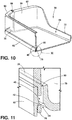
FIG. 10 is a cross-section view of the door bin unit ofFIG. 7 showing an attachment arrangement of an inner wall of the door bin unit with a bin body; and -
FIG. 11 is a detail view of the cross-section view ofFIG. 10 . - For purposes of description herein the terms "upper," "lower," "right," "left," "rear," "front," "vertical," "horizontal," and derivatives thereof shall relate to the device as oriented in
FIG. 1 . However, it is to be understood that the device may assume various alternative orientations and step sequences, except where expressly specified to the contrary. It is also to be understood that the specific devices and processes illustrated in the attached drawings, and described in the following specification are simply exemplary embodiments of the inventive concepts defined in the appended claims. Hence, specific dimensions and other physical characteristics relating to the embodiments disclosed herein are not to be considered as limiting, unless the claims expressly state otherwise. - Referring to the embodiment illustrated in
FIGS. 1-11 ,reference numeral 10 generally designates a refrigerator door bin assembly. Thedoor bin assembly 10 includes aliner 12 positioned along an interior of adoor 14 in an associatedrefrigerator 16. Theliner 12 defines first andsecond side walls second side walls base 22 extending inwardly with respect to the associated one of the first andsecond side walls bases 22 defines alocking channel 24 therein. Theassembly 10 further includes abin body 26 defining first and secondouter walls second side walls door liner 12. Each of the first and secondouter walls bin body 26 defines arespective alignment channel 32 receiving a respective one of the supportingbases 22 therein. Alocking rib 34 extends within thealignment channel 32 to engage with thelocking channel 24. - As shown in
FIGS. 1 and 2 , thebin body 26 of the bin assembly 10 (FIG. 7 ) is included in abin unit 36 that includes a separateinner wall 38 of a transparent material, thebin body 26 being of an opaque material. Theinner wall 38 is positioned between the first and secondouter walls bin body 26 and is coupled with thebin body 26 by engagement betweenopenings 40 in respective portions of theinner wall 38 andrespective locking pawls 42 extending from thebin body 26 in locations aligned with theopenings 40 such that thelocking pawls 42 are respectively engaged with theopenings 40, as shown inFIGS. 10 and 11 and discussed further below. It is noted that, although the embodiment shown and described herein includes the above-mentionedopenings 40 and lockingpawls 42 formed in theinner wall 38 and thebin body 26, respectively, a reversed arrangement is possible, wherein theopenings 40 are formed in thebin body 26 and thelocking pawls 42 are formed along theinner wall 38. - The locking arrangements between bin
unit 36, by way ofbin body 26, anddoor liner 12, as well as betweeninner wall 38 andbin body 26, can help to provide arobust bin assembly 10 that can be shipped without additional securement ofinner wall 38 tobin body 26 or ofbin body 26 toliner 12, which in other types of bin assemblies without such locking arrangements may be done using tape or the like. It is noted that such other types of assemblies may favor the ability of a consumer to easily adjust the positioning of door bins along a vertical height of the associated door. However, in many applications, at least a lower door bin can maximize utility be being positioned toward the bottom of the door. Even further, such door bins may not frequently, or ever, be adjusted or moved by the consumer, especially after the initial positioning of items in such bins. In this manner, a robust assembly may be favored over ease of adjustment. It is further noted that, depending on the particular configuration of the described locking arrangements, including with respect to material use, removal and repositioning of such bins may not be possible by the consumer. - Turning to
FIG. 3 , an example of arefrigerator 16, in which the herein-describedbin assembly 10 may be implemented, is shown. In particular, the depicted refrigerator is shown as a French-door, bottom-mount ("FDBM")type refrigerator 16, in which afresh food compartment 44 is positioned above afreezer compartment 46, and in which two separate outwardly-swingingdoors 14 are used to close the opening 48 to thefresh food compartment 44. In this manner, the above-mentioned first andsecond side walls door dyke 50 formed inliner 12 and generally surrounding the outer portion of the inside ofdoor 14. As shown, supportingbases 22 can be formed in thedoor dyke 50 at various, horizontally-aligned positions along the included first andsecond side walls positions 52 in which bin units 36 (FIGS. 1 and 2 ) can be assembled withdoor 14. In this manner,bin units 36 can be sized to extend across the width of the door dyke 50 (which corresponds generally with an overall width of the associated door 14) betweenside walls outer walls 28,30 (FIGS. 1 and 2 ) of bin body 26 (FIGS. 1 and 2 ) are appropriately positionedadjacent side walls bases 22 are appropriately received within alignment channels 32 (FIGS. 1 and 2 ). In the depicted FDBM arrangement forrefrigerator 16, bin positions 52 can be provided on bothdoors 14 by the appropriate incorporation of supportingbases 22 in therespective liners 12 of bothdoors 14 for the receipt ofbin units 36 insuch positions 52, thebin units 36 being generally symmetrical for positioning along eithersuch door 14. - The
bin assembly 10 described herein can also be implemented in other types of refrigerators, including single door bottom-mount arrangements or in both doors associated respectively with thefresh food compartment 44 andfreezer compartment 46 in a single door top-mount arrangement or in a side-by-side refrigerator. In general, thedoor bin assembly 10 described herein can be adapted for such use simply by scaling thebin unit 36 to an appropriate width to correspond with theparticular door 14 in which theassembly 10 is used. - Depending on the ultimate configuration of
bin assembly 10, according to the structures and principles discussed herein,bin assembly 10 can result inbin units 36 that are intended to be affixed in asingle position 52 alongdoor 14 and not subsequently moved by the consumer. Although removal ofbin body 26 from the resultingposition 52 alongdoor 14 may be possible, such removal may be made discouragingly difficult. Further, such movement may be discouraged by providing the same number ofpositions 52 asbin units 36 such that noalternative positions 52 forbins units 36 are available. Alternatively,bin units 36 may be made generally readily moveable (even at a generally higher removal or assembly force than other bin assembly arrangements), in which case additional,alternative positions 52 may be provided by the inclusion of additional pairs of supportingbases 22. - Turning to
FIGS. 6-9 , particular aspects of the engagement between supportingbases 22 andalignment channels 32 are described. As shown inFIG. 6 ,alignment channel 32 can be defined betweenopposite ribs 54 extending outwardly from the correspondingoutside wall bin body 26. As illustrated,ribs 54 can extend predominately in a vertical direction with respect tobin body 26 and can be spaced apart from each other at a distance sufficient to receive a corresponding supportingbase 22 therein.Ribs 54 can further taper somewhat toward each other in a direction toward theupper end 56 thereof. In this manner, engagement of supporting bases 22 (which can also taper inwardly alongouter surfaces 58 toward anupper surface 60 thereof) withincorresponding alignment channels 32 in a downward direction can cause supportingbases 22 to wedge intoalignment channels 32. In turn, this may help retainbin body 26 in an assembled arrangement withliner 12. Such wedging can also help stabilize the assembly ofbin body 26 withliner 12 and can prevent rattling ofbin body 26 againstliner 12, such as by vibration ofrefrigerator 16. The engagement of lockingrib 34 with lockingchannel 24, described further below, can maintainbin body 26 in the assembled position with respect toliner 12 against the upward force resulting from the wedging of supportingbases 26 intoalignment channels 32. - As further shown in
FIG. 6 , lockingrib 34 extends betweenalignment ribs 54 in a generally horizontal manner. Theend 56 ofalignment channel 32 similarly extends betweenalignment ribs 54 in a horizontal manner with lockingrib 34 spaced apart therefrom at a predetermined distance. In the illustrated embodiment, theend 56 ofalignment channel 32 is defined along a section of anupper lip 62 of theouter walls bin body 26 extending betweenalignment ribs 54, although a separate additional element (such as an additional rib) can define lockingrib 34. In this manner, as further shown inFIGS. 7-9 ,alignment ribs 54 andlip 62 can extend laterally outwardly fromouter walls respective side walls liner 12 with outer walls spaced apart therefrom to form a void in which supportingbases 22 are received. Such an arrangement allows a generally seamless appearance for the interior ofbin body 26 that obscures the presence ofalignment channel 32 and the associated support bases 22 (which is aided by the use of opaque material for bin body 26). - As illustrated in the assembly view of
FIG. 7 , as well as in the cross-section views ofFIGS. 8 and9 , the engagement of supportingbases 22 within the correspondingalignment channels 32positions locking rib 34 within lockingchannel 24 such thatbin body 26 is maintained in place relative toliner 12. As shown inFIG. 7 , supportingbase 22 includes the above-mentionedupper surface 60 spaced apart vertically from the position of lockingchannel 24. The position of lockingrib 34 relative to theend 56 ofalignment channel 32 corresponds with the spacing betweensurface 60 and an upper portion of locking channel such that, when supportingbase 22 is received with alignment channel 32 (including any compression or wedging, as discussed above) withend 56 ofalignment channel 32 contactingupper surface 60 of supportingbase 22, lockingrib 34 is positioned within lockingchannel 24. More particularly, as shown in the cross section view ofFIG. 9 , lockingrib 34 contacts an undercutsurface 64 defining the upper portion of lockingchannel 24 and facing oppositely fromupper surface 60. As can be appreciated, the configuration of undercutsurface 64 relative to lockingrib 34 can be derived to provide the desired retention characteristic of lockingrib 34 within lockingchannel 24. For example, undercutsurface 64 can be made longer and/or more horizontal relative to lockingrib 34 to increase the force needed inremoval direction 66 to dislodge lockingrib 34 from lockingchannel 24, essentially, by movement of lockingrib 34 over undercutsurface 64 and out of lockingchannel 24 by way of compression of supportingbase 22 in an area between lockingchannel 24 andupper surface 60, which may be facilitated by supportingbase 22 being generally hollow due to the vacuum-forming process used to fabricateliner 12. Removal of lockingrib 34 from lockingchannel 24 may be facilitated by a round are on outer portion of undercutsurface 64 and/or the particular depth or angle of undercutsurface 64. The lateral placement ofalignment ribs 54 against the correspondingouter surfaces 58 of supporting base 22 (as shown inFIG. 8 ) serves to prohibit lockingrib 34 from moving laterally out of lockingchannel 24. - As further shown in
FIG. 9 , when supportingbase 22 is fully assembled withinalignment channel 32,bin body 26 is vertically supported by the contact betweenend 56 ofalignment channel 32 andupper surface 60 ofsupport base 22. Such positioning can be achieved by alignment ofbin body 26 inliner 12 withsupport bases 22 aligned with corresponding ones of thealignment channels 32 on the oppositeouter walls 28, 30 (FIGS. 1 and 2 ).Bin body 26 can then be moved in theinstallation direction 68 to engagealignment channels 32 over supportingbases 22. Such movement will, at one stage,position locking ribs 34 against corresponding support bases 22. In the embodiment shown inFIG. 9 , in such a position, lockingribs 34 will contact atapered surface 70 that extends betweenupper surface 60 and undercutsurface 64. In this manner, lockingrib 34 can be sized relative to upper lip 62 (and, accordingly, end 56 of alignment channel 32) such that lockingrib 34 extends outwardly by a lesser distance thanupper lip 62. In one example, lockingrib 34 can extend to between about 30% and about 70% of the distance to whichupper lip 62 extends, and in a further example about 50% of the distance. In this manner, end 56 ofalignment channel 32 can extend outwardly to be in a position to contactupper surface 60, whereas lockingrib 34 is set inward relative toupper surface 60 to contact taperedsurface 70. Accordingly, taperedsurface 70 can be configured to allow lockingrib 34 to move over taperedsurface 70, including by compression of supportingbase 22 in a similar manner to that which is discussed above with respect to removal of lockingrib 34 from lockingchannel 24. As shown, taperedsurface 70 can be more steeply angled than undercutsurface 64 such that the force needed to engage lockingrib 34 with lockingchannel 24 is less than the force needed for subsequent removal. - Returning to
FIG. 7 , whenbin unit 36 and/orbin body 26 is assembled withliner 12, in the manner discussed above, amiddle wall 72 ofbin body 26 contacts aninner wall 74 ofliner 12 to furthersupport bin body 26 with respect toliner 12. In particular, such an arrangement can facilitate a cantilevered arrangement forbin unit 36, in which alower shelf 78 ofbin body 26 extends outwardly beyonddoor dyke 50. As shown,middle wall 72 can be tapered to a lower height thaninner wall 38 orouter walls middle wall 72 being of a height sufficient for contactinginner wall 74 ofliner 12 and to provide desired rigidity forbin body 26. - Continuing with respect to
FIG. 7 , and with additional reference toFIGS. 10 and 11 , the attachment ofinner wall 38 withbin body 26 is described. In the illustrated embodiment, the previously-describedopenings 40 can be positioned at generally regular intervals along a width ofinner wall 38. Such intervals can be between about 2 cm and about 5 cm, for example, although other spacings are possible, as dictated by the configuration of and/or materials used forinner wall 38 andbase body 26. As further shown,openings 40 can be defined on associatedtabs 76 extending downwardly from alower edge 78 ofinner wall 38. As shown inFIG. 11 , thetabs 76 can have a lesser material thickness than at least the portions ofinner wall 38 from which they extend. In this manner,tabs 76 can extend into achannel 80 extending on theinner edge 82 of theshelf 78 defined on the lower portion ofbin body 26. As further shown, the above-mentionedlocking pawls 42 can be positioned withinchannel 80 such thattabs 76 can extend withinchannel 80 to position lockingpawls 42 withinopenings 40 for securement ofinner wall 38. In a further aspect,channel 80 may be generally closed with a plurality ofslots 84 therethrough corresponding to the position oftabs 76 for receipt therethrough to allow flexing oftabs 76 over lockingpawls 42 to position lockingpawls 42 withinopenings 40, which can also be facilitated by outward flexing of the portions ofbin body 26 bounding theslots 84 throughchannel 80. This arrangement facilities a robust snap-fit assembly ofinner wall 38 withbin body 26. Again, it is noted that a reverse arrangement is possible, in which lockingpawls 42 are positioned ontabs 76 and engage with openings 40 (which may be blind openings that could be further characterized as detents) withinchannel 80 or the like. - As further shown in
FIGS. 7 and10 ,detents 86 can be present along the upper ends 88 ofinner wall 38, which may be defined along anupper lip 90 thereof. Thedetents 86 can engage withcorresponding hooks 92 or the like present in adjacent portions ofbin body 26, which can include along portions ofouter walls inner wall 38 in contact withouter walls inner wall 38 is assembled withbin body 26 by way of the above-described snap-fit ofopenings 40 on lockingpawls 42. - It will be understood by one having ordinary skill in the art that construction of the described device and other components is not limited to any specific material. Other exemplary embodiments of the device disclosed herein may be formed from a wide variety of materials, unless described otherwise herein.
- For purposes of this disclosure, the term "coupled" (in all of its forms, couple, coupling, coupled, etc.) generally means the joining of two components (electrical or mechanical) directly or indirectly to one another. Such joining may be stationary in nature or movable in nature. Such joining may be achieved with the two components (electrical or mechanical) and any additional intermediate members being integrally formed as a single unitary body with one another or with the two components. Such joining may be permanent in nature or may be removable or releasable in nature unless otherwise stated.
- It is also important to note that the construction and arrangement of the elements of the device as shown in the exemplary embodiments is illustrative only. Although only a few embodiments of the present innovations have been described in detail in this disclosure, those skilled in the art who review this disclosure will readily appreciate that many modifications are possible (e.g., variations in sizes, dimensions, structures, shapes and proportions of the various elements, values of parameters, mounting arrangements, use of materials, colors, orientations, etc.) without materially departing from the novel teachings and advantages of the subject matter recited. For example, elements shown as integrally formed may be constructed of multiple parts or elements shown as multiple parts may be integrally formed, the operation of the interfaces may be reversed or otherwise varied, the length or width of the structures and/or members or connector or other elements of the system may be varied, the nature or number of adjustment positions provided between the elements may be varied. It should be noted that the elements and/or assemblies of the system may be constructed from any of a wide variety of materials that provide sufficient strength or durability, in any of a wide variety of colors, textures, and combinations. Accordingly, all such modifications are intended to be included within the scope of the present innovations. Other substitutions, modifications, changes, and omissions may be made in the design, operating conditions, and arrangement of the desired and other exemplary embodiments without departing from the spirit of the present innovations.
- It will be understood that any described processes or steps within described processes may be combined with other disclosed processes or steps to form structures within the scope of the present device. The exemplary structures and processes disclosed herein are for illustrative purposes and are not to be construed as limiting.
- It is also to be understood that variations and modifications can be made on the aforementioned structures and methods without departing from the concepts of the present device, and further it is to be understood that such concepts are intended to be covered by the following claims unless these claims by their language expressly state otherwise.
- The above description is considered that of the illustrated embodiments only. Modifications of the device will occur to those skilled in the art and to those who make or use the device. Therefore, it is understood that the embodiments shown in the drawings and described above is merely for illustrative purposes and not intended to limit the scope of the device, which is defined by the following claims as interpreted according to the principles of patent law, including the Doctrine of Equivalents.
Claims (15)
- A refrigerator door bin assembly (10), said assembly comprising:a door liner (12) defining a first side wall (18) defining a supporting base (22) extending from the first side wall (18), the supporting base (22) defining a locking channel (24) therein; anda bin body (26) defining a first outer wall facing and positioned adjacent to the first side wall (18) of the door liner (12), the first outer wall of the bin body (26) defining an alignment channel (32) receiving the supporting base (22) therein, a locking rib (34) extending within the alignment channel (32) to engage with the locking channel (24).
- The refrigerator door bin assembly (10) of claim 1, wherein:the door liner (12) further defines a second side wall (20) spaced apart from and facing the first side wall (18);each of the first and second side walls (18, 20) define a respective supporting base (22) extending inwardly with respect to the associated one of the first and second side walls (18, 20); andeach of the supporting bases (22) defining a locking channel (24) therein.
- The refrigerator door bin assembly (10) of claim 2, wherein:the bin body (26) further defines a second outer wall;each of the first and second outer walls face and are positioned adjacent to respective ones of the first and second side walls (18, 20) of the door liner (12); andeach of the first and second outer walls of the bin body (26) define a respective alignment channel (32) receiving a respective one of the supporting bases (22) therein, a respective locking rib (34) extending within each alignment channel (32) to engage therewith.
- The refrigerator door bin assembly (10) of claim 1, wherein the alignment channel (32) includes a closed end contacting and supporting the bin body (26) on an adjacent surface of the supporting base (22).
- The refrigerator door bin assembly (10) of claim 4, wherein the locking rib (34) extends parallel with the closed end of the alignment channel (32) and opposes movement of the bin body (26) in a removal direction wherein the closed end of the channel (24) moves away from the adjacent surface of the supporting base (22).
- The refrigerator door bin assembly (10) of claim 1, wherein:the supporting base (22) defines a wedge shape tapering outwardly from a supporting surface thereof; andthe alignment channel (32) is tapered to match the wedge shape of the supporting base (22).
- The refrigerator door bin assembly (10) of claim 1, wherein:the alignment channel (32) is defined by first and second side ribs and an upper wall extending between the first and second side ribs, the locking rib (34) also extending between the first and second side ribs generally parallel to the upper wall; andthe locking rib (34) is recessed with respect to the upper wall and the first and second side ribs.
- The refrigerator door bin assembly (10) of claim 1, wherein the supporting base (22) defines an upper supporting surface and an inner face, the inner face being angled toward the first wall in a direction from the locking channel (24) toward the supporting surface.
- The refrigerator door bin assembly (10) of claim 8, wherein the supporting base (22) further defines a rounded edge between the face and the locking channel (24).
- The refrigerator door bin assembly (10) of claim 1, further including an inner wall (38) of a transparent material wall, wherein the bin body (26) is of an opaque material.
- The refrigerator door bin assembly (10) of claim 10, wherein the inner wall (38) is coupled with the bin body (26) by an opening (40) in one of the inner wall (38) or the bin body (26) receiving locking pawl (42) therein, the locking pawl (42) extending from the other of the bin body (26) or inner wall (38).
- The refrigerator door bin assembly (10) of claim 11, wherein the opening (40) is one of a plurality of openings (40) in respective ones of a plurality of tabs extending from a lower surface of the inner wall (38).
- The refrigerator door bin assembly (10) of claim 12, wherein the locking pawls (42) extend from the bin body (26) within a channel (24) disposed along an inside edge of a shelf defined on a lower surface of the bin body (26), the tabs of the inner wall (38) extending within the channel (24).
- The refrigerator door bin assembly (10) of claim 13, wherein a the bin body (26) defines a generally flat outer surface opposite the channel (24), the inner wall (38) extending generally flush with the generally flat outer surface.
- The refrigerator door bin assembly (10) of claim 13, wherein:the inner wall (38) includes an upper edge with opposed detents on respective ends of the upper edge; andthe bin body (26) includes respective hooks engaging with detents.
Applications Claiming Priority (2)
| Application Number | Priority Date | Filing Date | Title |
|---|---|---|---|
| US201762539674P | 2017-08-01 | 2017-08-01 | |
| US16/050,421 US10677514B2 (en) | 2017-08-01 | 2018-07-31 | Door bin with dual material and system lock |
Publications (1)
| Publication Number | Publication Date |
|---|---|
| EP3438580A1 true EP3438580A1 (en) | 2019-02-06 |
Family
ID=63142967
Family Applications (1)
| Application Number | Title | Priority Date | Filing Date |
|---|---|---|---|
| EP18186835.7A Withdrawn EP3438580A1 (en) | 2017-08-01 | 2018-08-01 | Door bin with dual material and locking system |
Country Status (2)
| Country | Link |
|---|---|
| US (1) | US10677514B2 (en) |
| EP (1) | EP3438580A1 (en) |
Cited By (1)
| Publication number | Priority date | Publication date | Assignee | Title |
|---|---|---|---|---|
| WO2021256783A1 (en) * | 2020-06-17 | 2021-12-23 | Samsung Electronics Co., Ltd. | Refrigerator |
Families Citing this family (5)
| Publication number | Priority date | Publication date | Assignee | Title |
|---|---|---|---|---|
| DE102017216288A1 (en) * | 2017-09-14 | 2019-03-14 | BSH Hausgeräte GmbH | Door racks for a refrigeration device |
| US11015860B1 (en) | 2019-12-18 | 2021-05-25 | Electrolux Home Products, Inc. | Door bins and door liner interface |
| USD1059429S1 (en) * | 2021-01-06 | 2025-01-28 | Sub-Zero Group, Inc. | Door shelf |
| US20230152031A1 (en) * | 2021-11-16 | 2023-05-18 | Whirlpool Corporation | Modular appliance bin |
| US12031770B2 (en) | 2022-02-15 | 2024-07-09 | Whirlpool Corporation | Storage assembly for an appliance |
Citations (10)
| Publication number | Priority date | Publication date | Assignee | Title |
|---|---|---|---|---|
| GB851667A (en) * | 1958-03-29 | 1960-10-19 | Bosch Gmbh Robert | Improvements in refrigerator doors |
| JPS61124884U (en) * | 1985-01-21 | 1986-08-06 | ||
| JPS6212485U (en) * | 1985-07-04 | 1987-01-26 | ||
| JPH04278171A (en) * | 1991-03-01 | 1992-10-02 | Sharp Corp | Structure for receiving section of refrigerator |
| US20040108799A1 (en) * | 2002-12-09 | 2004-06-10 | Maytag Corporation | Refrigerator door storage systems |
| CA2484872A1 (en) * | 2004-10-15 | 2006-04-15 | Maytag Corporation | Storage bin assembly for a refrigerator |
| DE102005022516A1 (en) * | 2005-05-11 | 2006-11-16 | BSH Bosch und Siemens Hausgeräte GmbH | Door racks for a refrigeration device |
| CN102997580A (en) * | 2012-12-31 | 2013-03-27 | 合肥美的荣事达电冰箱有限公司 | Refrigerator |
| CN105318639A (en) * | 2015-09-25 | 2016-02-10 | 青岛海尔股份有限公司 | Refrigerator and refrigerator sealing box |
| CN104697286B (en) * | 2015-03-31 | 2017-04-12 | 海信(山东)冰箱有限公司 | Refrigerator and structure for fixing door shelf of refrigerator |
Family Cites Families (278)
| Publication number | Priority date | Publication date | Assignee | Title |
|---|---|---|---|---|
| US774117A (en) | 1904-03-04 | 1904-11-01 | John L Tandy | Display-cabinet. |
| US1952148A (en) | 1929-07-01 | 1934-03-27 | Frigidaire Corp | Refrigerating apparatus |
| US1997432A (en) | 1932-02-01 | 1935-04-09 | Copeland Refrigeration Corp | Shelf construction |
| US2065391A (en) | 1933-10-19 | 1936-12-22 | Gen Motors Corp | Refrigerating apparatus |
| US2187916A (en) | 1936-01-23 | 1940-01-23 | Seeger Refrigerator Co | Refrigerator |
| US2225762A (en) | 1937-11-30 | 1940-12-24 | Westinghouse Electric & Mfg Co | Oven rack glide |
| US2282342A (en) | 1940-01-26 | 1942-05-12 | Gen Motors Corp | Refrigerating apparatus |
| US2412904A (en) | 1941-12-10 | 1946-12-17 | Crosley Corp | Refrigerating apparatus |
| US2434117A (en) | 1941-12-10 | 1948-01-06 | Avco Mfg Corp | Shelf structure with guard for refrigerator doors |
| US2466360A (en) | 1945-12-15 | 1949-04-05 | Union Steel Prod Co | Rack assembly for refrigerators, ovens, and the like |
| US2517385A (en) | 1947-04-04 | 1950-08-01 | Int Harvester Co | Fold-away shelf for refrigerators or the like |
| US2573272A (en) | 1947-07-21 | 1951-10-30 | Gen Motors Corp | Storage drawer for refrigerating apparatus |
| US2509592A (en) | 1947-08-15 | 1950-05-30 | Nash Kelvinator Corp | Refrigerating apparatus having receptacle secured to door |
| US2597267A (en) | 1949-11-29 | 1952-05-20 | Philco Corp | Refrigerator having an evaporator provided with a movable section |
| US2694906A (en) | 1951-12-05 | 1954-11-23 | Gen Motors Corp | Refrigerating apparatus having a hydrator receptacle |
| US2773677A (en) | 1952-05-03 | 1956-12-11 | Whirlpool Seeger Corp | Inner liner with butter compartment for refrigerator door |
| US2710993A (en) | 1952-07-09 | 1955-06-21 | Gen Electric | Insulated door structures |
| US2737782A (en) | 1953-01-06 | 1956-03-13 | Philco Corp | Plural compartment refrigerator |
| US2748573A (en) | 1953-01-21 | 1956-06-05 | Philco Corp | Refrigerator having an adjustable evaporator construction |
| US2742559A (en) | 1953-02-12 | 1956-04-17 | Edelman Irving | Removable tray support for rotisserie |
| US2804068A (en) | 1953-03-12 | 1957-08-27 | Admiral Corp | Adjustable oven rack |
| US2875016A (en) | 1954-07-22 | 1959-02-24 | Gen Motors Corp | Domestic appliances |
| US2841132A (en) | 1954-10-25 | 1958-07-01 | American Motors Corp | Range |
| US3266858A (en) | 1964-03-12 | 1966-08-16 | American Motors Corp | Refrigerator cabinet storage compartment construction |
| US3295904A (en) | 1964-12-18 | 1967-01-03 | Westinghouse Electric Corp | Container assembly |
| US3410260A (en) | 1966-10-31 | 1968-11-12 | Borg Warner | Liner support useable with oven enclosures or the like |
| US3866437A (en) | 1973-09-10 | 1975-02-18 | Westinghouse Electric Corp | Adjustable damper control mechanism |
| US3984163A (en) | 1975-12-22 | 1976-10-05 | General Electric Company | Cantilever sliding shelf including a shelf removal notch on one side only |
| JPS52126461U (en) | 1976-03-24 | 1977-09-26 | ||
| US4638644A (en) | 1978-04-07 | 1987-01-27 | Edward Gidseg | Circulating air refrigerator with removable divider shelf |
| DE10208058B4 (en) | 2002-02-25 | 2018-10-25 | BSH Hausgeräte GmbH | The refrigerator |
| US4597616A (en) | 1984-10-30 | 1986-07-01 | Cari-All Inc. | Drawer-like container assembly |
| JPS61124884A (en) | 1984-11-21 | 1986-06-12 | Toshiba Corp | Apparatus for counting radiation pulse |
| JPS6212485A (en) | 1985-07-09 | 1987-01-21 | スズキ株式会社 | Seat regulator for motorcycle |
| US4735470A (en) | 1986-03-28 | 1988-04-05 | General Electric Company | Refrigerator including a secondary food storage arrangement |
| US4732435A (en) | 1986-11-07 | 1988-03-22 | Whirlpool Corporation | Refrigerator crisper drawer structure |
| US4729613A (en) | 1986-11-13 | 1988-03-08 | General Electric Company | Household refrigerator pan assembly |
| DE8710846U1 (en) | 1987-08-05 | 1987-10-01 | Siemens Ag, 1000 Berlin Und 8000 Muenchen | Bracket for a guide roller on a support part |
| DE8801508U1 (en) | 1988-02-06 | 1989-06-08 | Licentia Patent-Verwaltungs-Gmbh, 6000 Frankfurt | Storage area with built-in drawer, especially for household refrigerators and fridge-freezers |
| US4908544A (en) * | 1988-08-03 | 1990-03-13 | Whirlpool Corporation | Storage bin mounting system for a refrigerator and method of assembly |
| US4914928A (en) | 1988-08-29 | 1990-04-10 | Whirlpool Corporation | Manual air damper control for a refrigerator |
| US4998382A (en) | 1989-12-11 | 1991-03-12 | Ardco, Inc. | Insulated refrigerator door assembly with substantially all glass front doors |
| US5088801A (en) | 1990-06-12 | 1992-02-18 | Westinghouse Electric Corp. | File holders and briefcase therefor |
| US5564809A (en) | 1991-03-07 | 1996-10-15 | Donnelly Technology, Inc. | Encapsulated shelf for refrigerated compartments |
| US5362145A (en) | 1991-03-07 | 1994-11-08 | Donnelly Corporation | Molded refrigerator shelf |
| US5273354A (en) | 1991-03-07 | 1993-12-28 | Donnelly Corporation | Molded refrigerator shelf and support bracket |
| CA2089138A1 (en) | 1992-02-10 | 1993-08-11 | Richard Alan Brise | Portable shelf |
| DE9209216U1 (en) | 1992-07-09 | 1992-08-27 | Bosch-Siemens Hausgeräte GmbH, 8000 München | Shelf for dividing the interior of a piece of furniture |
| CA2094836C (en) | 1992-07-13 | 2000-02-29 | Edmund J. Kane | Molded refrigerator shelf with snap-in slide |
| US5469999A (en) | 1993-07-29 | 1995-11-28 | Phirippidis; George | Modular storage and organizing system for vehicles |
| US5411165A (en) | 1993-11-02 | 1995-05-02 | Ellis; Thomas J. | Drawer and insert for rapid removal of valuables |
| US5447146A (en) | 1994-02-07 | 1995-09-05 | Nickerson; Larry D. | Oven rack assembly |
| US5660777A (en) | 1994-04-29 | 1997-08-26 | Donnelly Technology, Inc. | Method for making a sliding refrigerator shelf assembly |
| CA2146791C (en) | 1994-04-29 | 2002-06-25 | Robert S. Herrmann | Sliding refrigerator shelf assembly |
| US5605344A (en) | 1994-09-14 | 1997-02-25 | Herman Miller, Inc. | Transport cart |
| ES2190153T3 (en) | 1994-09-07 | 2003-07-16 | Miller Herman Inc | TOWER OF DRAWERS. |
| US5429043A (en) | 1994-10-24 | 1995-07-04 | Becker; Ruby | Power operated adjustable oven rack |
| US5813741A (en) | 1996-01-23 | 1998-09-29 | White Consolidated Industries, Inc. | Adjustable shelf for a refrigerator |
| JPH10115485A (en) | 1996-10-09 | 1998-05-06 | Fujitsu General Ltd | Refrigerator door storage device |
| JPH10122733A (en) | 1996-10-18 | 1998-05-15 | Fujitsu General Ltd | Refrigerator door storage device |
| KR19980056962A (en) | 1996-12-30 | 1998-09-25 | 배순훈 | Refrigerator with multiple vegetable boxes |
| US5833336A (en) | 1997-08-18 | 1998-11-10 | Dean; W. Anthony | Partitioned stylish hamper |
| US5947573A (en) | 1997-11-12 | 1999-09-07 | Whirlpool Corporation | Refrigerator and compartment therefor |
| DE19750473A1 (en) | 1997-11-14 | 1999-05-20 | Aeg Hausgeraete Gmbh | Folding shelf |
| US6045101A (en) | 1998-01-30 | 2000-04-04 | Waltec Plastics Inc. | Article support |
| JPH11237173A (en) | 1998-02-24 | 1999-08-31 | Matsushita Refrig Co Ltd | Door shelf for refrigerator |
| US6174482B1 (en) | 1998-10-26 | 2001-01-16 | Gemtron Corporation | Method of manufacturing an interlocked, “flush-to-front,” injection molded border and glass sheet |
| KR100364994B1 (en) | 1999-11-26 | 2002-12-16 | 주식회사 엘지이아이 | Moving device for traymeat in refrigerator |
| KR100374557B1 (en) | 2000-01-06 | 2003-03-04 | 주식회사 엘지이아이 | Reinforced glass for refrigerator |
| US6811045B1 (en) | 2000-01-10 | 2004-11-02 | General Electric Company | Spillproof refrigerator shelf |
| IT1317464B1 (en) | 2000-05-05 | 2003-07-09 | Whirlpool Co | REFRIGERATOR WITH VARIABLE VOLUME COMPARTMENT |
| US6220684B1 (en) | 2000-07-13 | 2001-04-24 | Maytag Corporation | Adjustable retainer assembly for a refrigerator door shelf |
| WO2002014761A1 (en) | 2000-08-17 | 2002-02-21 | Arçelik A.S. | Storage container for refrigerators |
| JP2002090054A (en) | 2000-09-20 | 2002-03-27 | Fujitsu General Ltd | Refrigerator shelf equipment |
| US6488347B1 (en) | 2000-11-21 | 2002-12-03 | Gemtron Corporation | Refrigerator shelf with one-piece internally ribbed/reinforced polymeric frame and reinforced suspension hooks |
| US6523719B2 (en) | 2000-12-04 | 2003-02-25 | True Manufacturing Co., Inc. | Container dispenser for merchandiser |
| KR100356542B1 (en) | 2000-12-29 | 2002-10-19 | 삼성전자 주식회사 | Refrigerator Having Freezing Compartment |
| DE10107646A1 (en) | 2001-02-19 | 2002-08-29 | Bsh Bosch Siemens Hausgeraete | Pull-out vegetable box, for a refrigerator, has an insert box removably mounted on the upper edge of the pull-out box and having a size corresponding to the width of the pull-out box |
| US6582038B2 (en) * | 2001-07-12 | 2003-06-24 | Comercial Acros Whirlpool, S.A. De C.V. | Storage bin mounting system for a refrigerator door |
| CA2453611A1 (en) | 2001-07-16 | 2003-01-30 | Maytag Corporation | Refrigerator shelves with rolled hook for cantilever fastening |
| US6905183B2 (en) | 2001-07-16 | 2005-06-14 | Maytag Corporation | Tilt-out door buckets for refrigerators or freezers |
| DE10148406A1 (en) | 2001-10-01 | 2003-04-17 | Bsh Bosch Siemens Hausgeraete | Insert for a door storage compartment |
| US6799818B2 (en) * | 2001-10-31 | 2004-10-05 | General Electric Company | Tiltable storage module for refrigerator |
| US6742855B2 (en) * | 2001-11-30 | 2004-06-01 | General Electric Company | Freezer tip out bin |
| US6604800B2 (en) | 2001-12-20 | 2003-08-12 | Maytag Corporation | Refrigerator shelving assembly |
| KR100431346B1 (en) | 2002-01-15 | 2004-05-12 | 삼성전자주식회사 | Refrigerator having shelf |
| US6578720B1 (en) | 2002-02-08 | 2003-06-17 | I Jang Industrial Co., Ltd. | Rack comprising adjustable slide rails |
| US7270385B2 (en) | 2002-02-12 | 2007-09-18 | General Electric Company | Spill proof shelf assembly method and structure |
| USD482705S1 (en) | 2002-02-14 | 2003-11-25 | U-Line Corporation | Shelf front |
| DE10208056A1 (en) | 2002-02-25 | 2003-09-04 | Bsh Bosch Siemens Hausgeraete | Edge finishing part for a glass plate |
| CA2479648C (en) | 2002-04-03 | 2011-10-25 | Lg Electronics Inc. | Door apparatus for drawer type refrigerator |
| DE10216769A1 (en) | 2002-04-15 | 2003-11-06 | Schott Glas | Method for supporting shelf in domestic refrigerator or freezer has support elements slideably attached to vertical rails on sides of appliance |
| KR100850005B1 (en) | 2002-05-27 | 2008-08-04 | 엘지전자 주식회사 | Shelf for refrigerator |
| US20040012314A1 (en) | 2002-07-17 | 2004-01-22 | Hay Michael E. | Removable tilting bin system |
| DE10254670A1 (en) | 2002-11-22 | 2004-06-24 | Minebea Co., Ltd. | Electric motor for a pump drive |
| KR100857605B1 (en) | 2002-11-27 | 2008-09-09 | 삼성전자주식회사 | Refrigerator |
| KR20040070986A (en) | 2003-02-05 | 2004-08-11 | 엘지전자 주식회사 | Movable shelf and refrigerator having the same |
| US7111914B2 (en) * | 2003-03-12 | 2006-09-26 | Maytag Corporation | Tilt-out and pick-off basket assembly for a refrigerator door |
| USD547640S1 (en) | 2003-04-28 | 2007-07-31 | Clairson, Inc. | Drawer bracket |
| KR100911272B1 (en) | 2003-04-28 | 2009-08-11 | 엘지전자 주식회사 | Refrigerator drawers |
| US7021730B2 (en) | 2003-04-28 | 2006-04-04 | Clairson, Inc. | Drawer bracket |
| US7497533B2 (en) | 2003-04-28 | 2009-03-03 | Clairson, Inc. | Shelves, resilient drawer stops, and drawer brackets for supporting shelves and drawers |
| DE10323852A1 (en) | 2003-05-26 | 2004-12-16 | BSH Bosch und Siemens Hausgeräte GmbH | Pull-out box for a refrigerator |
| TR200602027T1 (en) | 2003-08-05 | 2007-02-21 | Ar�El�K Anon�M ��Rket� | A cooler |
| KR20050028265A (en) | 2003-09-18 | 2005-03-22 | 엘지전자 주식회사 | Device for lifting shelf for refrigerator |
| KR100953977B1 (en) | 2003-10-04 | 2010-04-21 | 엘지전자 주식회사 | Refrigerator Door Basket |
| KR100555826B1 (en) | 2003-10-04 | 2006-03-03 | 엘지전자 주식회사 | Refrigerator |
| US7131545B1 (en) | 2003-10-06 | 2006-11-07 | Thomas A Grogan | Glass rack |
| US7188738B2 (en) | 2004-03-18 | 2007-03-13 | Customer Advantage Llc | Medication minder |
| BRPI0401193A (en) | 2004-04-01 | 2005-11-22 | Multibras Eletrodomesticos Sa | Cooling appliance |
| US7367571B1 (en) | 2004-05-07 | 2008-05-06 | Stainbrook & Stainbrook, Llp | Tool and task box storage, transport, and workbench system |
| AU2004242445B2 (en) | 2004-07-16 | 2006-02-02 | Lg Electronics Inc | Refrigerator having basket lift apparatus |
| GB2417671B (en) | 2004-09-07 | 2007-08-08 | Lg Electronics Inc | Double drawer of refrigerator |
| USD525633S1 (en) | 2004-11-15 | 2006-07-25 | Saint Gobain Glass France | Refrigerator shelf |
| USD516100S1 (en) | 2004-11-15 | 2006-02-28 | Saint Gobain Glass France | Refrigerator shelf |
| KR100559722B1 (en) | 2004-11-20 | 2006-03-10 | 엘지전자 주식회사 | Shelf of refrigerator |
| USD515599S1 (en) | 2004-11-22 | 2006-02-21 | Saint-Gobain Glass France | Refrigerator shelf |
| US20060145577A1 (en) | 2005-01-06 | 2006-07-06 | Gemtron Corporation | Shelf assembly for a refrigerator compartment |
| US8562089B2 (en) | 2005-01-12 | 2013-10-22 | Whirlpool Corporation | Refrigerator shelf retainer and divider assembly for tall packages |
| ITTO20050104A1 (en) | 2005-02-22 | 2006-08-23 | Itw Ind Components Srl | DRAWER CONTAINER DEVICE FOR A APPLIANCE, IN PARTICULAR FOR THE SECTOR FRESH FOOD OF A REFRIGERATOR OR FREEZER |
| KR20060106338A (en) | 2005-04-08 | 2006-10-12 | 엘지전자 주식회사 | Refrigerator with Home Bar Door |
| KR100662405B1 (en) | 2005-04-11 | 2007-01-02 | 엘지전자 주식회사 | Drawer |
| US7748806B2 (en) | 2005-08-29 | 2010-07-06 | Whirlpool Corporation | Encapsulated sliding shelf and over-molded frame |
| ITMI20052138A1 (en) | 2005-11-09 | 2007-05-10 | Whirlpool Co | SELF-SUPPORTING SHELF FOR MOBILE IN PARTICULAR FOR REFRIGERATOR |
| US7469553B2 (en) | 2005-11-21 | 2008-12-30 | Whirlpool Corporation | Tilt-out ice bin for a refrigerator |
| CN1975301B (en) | 2005-11-28 | 2010-12-29 | 海尔集团公司 | Shelves for refrigerators with partially sliding shelves |
| USD551884S1 (en) | 2006-01-04 | 2007-10-02 | Clairson, Inc. | Shelf |
| USD551262S1 (en) | 2006-02-23 | 2007-09-18 | Bsh Bosch Und Siemens Hausgeraete Gmbh | Refrigerator shelf |
| US7775613B2 (en) | 2006-03-06 | 2010-08-17 | Intier Automotive Inc. | Storage assembly |
| US20070235397A1 (en) | 2006-03-30 | 2007-10-11 | Wannop George M | Storage bin and frame system |
| US7651182B2 (en) * | 2006-03-31 | 2010-01-26 | Maytag Corporation | Adjustable retainer assembly for a refrigerator door storage unit |
| DE202006007339U1 (en) | 2006-05-08 | 2006-07-13 | BSH Bosch und Siemens Hausgeräte GmbH | Impeller for a rail-guided refrigerated goods carrier |
| WO2008015180A2 (en) | 2006-07-31 | 2008-02-07 | Arcelik Anonim Sirketi | A refrigerator |
| US8640482B2 (en) | 2006-08-11 | 2014-02-04 | Samsung Electronics Co., Ltd. | Refrigerator having folding shelf |
| KR100756887B1 (en) | 2006-09-25 | 2007-09-07 | 주식회사 대우일렉트로닉스 | Folding shelf in refrigerator |
| US8739568B2 (en) | 2008-03-12 | 2014-06-03 | Whirlpool Corporation | Appliance feature module enabled by energy or materials sourced from the host appliance |
| TWI416055B (en) | 2007-02-13 | 2013-11-21 | 松下電器產業股份有限公司 | Refrigerator |
| KR101362377B1 (en) | 2007-02-26 | 2014-02-12 | 삼성전자주식회사 | Variable shelf assembly and refrigerator having the same |
| DE102007021569A1 (en) | 2007-05-08 | 2008-11-13 | BSH Bosch und Siemens Hausgeräte GmbH | refrigerated goods |
| CA2595278C (en) | 2007-08-06 | 2011-05-03 | Go Simon Sunatori | Self-sealing auto-aligning magnetically-hanging spice dispenser |
| KR101357339B1 (en) | 2007-06-20 | 2014-02-03 | 엘지전자 주식회사 | Home bar for refrigerator |
| KR20080111833A (en) | 2007-06-20 | 2008-12-24 | 엘지전자 주식회사 | Refrigerator |
| US8182056B2 (en) | 2007-09-05 | 2012-05-22 | Electrolux Home Products, Inc. | Offset weight supporting slide |
| MX2007016337A (en) | 2007-12-18 | 2009-06-18 | Mabe Sa De Cv | Damper. |
| ITTO20070928A1 (en) | 2007-12-20 | 2009-06-21 | Indesit Co Spa | DRAWER FOR A REFRIGERATION SYSTEM AND ITS REFRIGERATION APPARATUS |
| US8414095B2 (en) | 2008-01-23 | 2013-04-09 | Ssw Holding Company, Inc. | Full extension refrigerator shelf and basket system |
| US8231190B2 (en) | 2008-02-01 | 2012-07-31 | Whirlpool Corporation | Articulated freezer drawers |
| BRPI0800491A2 (en) | 2008-02-29 | 2009-06-13 | Deud Laktim Jr | mobile phone integration system with integrated virtual fixed line networks |
| KR101554852B1 (en) | 2008-03-06 | 2015-09-23 | 삼성전자 주식회사 | Refrigerator |
| US7878344B2 (en) | 2008-04-03 | 2011-02-01 | Electrolux Home Products, Inc. | Tuck and store rack |
| US8726689B2 (en) | 2008-05-06 | 2014-05-20 | Samsung Electronics Co., Ltd. | Refrigerator with cold storage unit |
| DE102008026383A1 (en) | 2008-06-02 | 2009-12-03 | BSH Bosch und Siemens Hausgeräte GmbH | Domestic appliance with a door having a braking device |
| BRMU8802268Y1 (en) | 2008-06-26 | 2017-04-04 | Electrolux Do Brasil Sa | sliding shelf guides for refrigerators |
| US8286561B2 (en) | 2008-06-27 | 2012-10-16 | Ssw Holding Company, Inc. | Spill containing refrigerator shelf assembly |
| BRPI0803841A2 (en) | 2008-07-07 | 2010-03-09 | Whirlpool Sa | system for moving a set of refrigeration equipment shelves and refrigeration equipment |
| BRPI0802420A2 (en) | 2008-07-07 | 2010-03-09 | Whirlpool Sa | mechanism for moving shelves of refrigeration equipment and refrigeration equipment |
| US20100024464A1 (en) | 2008-08-04 | 2010-02-04 | Samsung Electronics Co., Ltd. | Refrigerator |
| KR20100022742A (en) * | 2008-08-20 | 2010-03-03 | 엘지전자 주식회사 | A refrigerator |
| KR101586306B1 (en) | 2008-08-22 | 2016-01-18 | 엘지전자 주식회사 | Refrigerator |
| KR20100026614A (en) | 2008-09-01 | 2010-03-10 | 삼성광주전자 주식회사 | A refrigerator |
| CA2639671C (en) | 2008-09-22 | 2014-08-05 | Go Simon Sunatori | Magnetically-hanging spice dispenser with a continuously-variable hole-size selector |
| CA2639670C (en) | 2008-09-22 | 2014-08-26 | Go Simon Sunatori | No-glue construction for a magnetically-hanging spice dispenser |
| US8047397B2 (en) | 2008-10-06 | 2011-11-01 | Theodore Mittet | Storage container holder |
| US9250010B2 (en) | 2009-01-16 | 2016-02-02 | Whirlpool Corporation | Refrigerator shelf with glass receiving slot |
| US8348362B2 (en) | 2009-02-27 | 2013-01-08 | Electrolux Home Products, Inc. | Pivoting lid for refrigerator door |
| DE102009002061A1 (en) | 2009-03-31 | 2010-10-14 | BSH Bosch und Siemens Hausgeräte GmbH | Household refrigerator |
| BRMU8900569U2 (en) | 2009-04-16 | 2010-12-21 | Electrolux Do Brasil Sa | sliding shelves for refrigerators and freezers |
| DE202009004771U1 (en) | 2009-04-30 | 2010-09-09 | Paul Hettich Gmbh & Co. Kg | Device for adjusting the height of a guided in a household appliance via at least one pullout guide tray |
| KR101602215B1 (en) | 2009-05-08 | 2016-03-21 | 엘지전자 주식회사 | Keeping device for refrigerator and refrigerator having the same |
| KR20100122155A (en) | 2009-05-12 | 2010-11-22 | 엘지전자 주식회사 | Refrigerator |
| KR101410460B1 (en) | 2009-07-02 | 2014-06-27 | 삼성전자주식회사 | Variable lathe and refrigerator with it |
| DE102009027887A1 (en) | 2009-07-21 | 2011-01-27 | BSH Bosch und Siemens Hausgeräte GmbH | Height-adjustable refrigerated goods carrier |
| DE102009045363B4 (en) | 2009-10-06 | 2023-02-23 | BSH Hausgeräte GmbH | Door rack for a refrigerator |
| US20110115356A1 (en) | 2009-11-18 | 2011-05-19 | Jonathan Nash | Shelf for an appliance |
| US9217601B2 (en) | 2009-12-22 | 2015-12-22 | Lg Electronics Inc. | Refrigerator with a convertible compartment |
| WO2011080109A2 (en) | 2009-12-31 | 2011-07-07 | Arcelik Anonim Sirketi | A refrigerator comprising flap doors |
| KR20120009645A (en) | 2010-07-20 | 2012-02-02 | 엘지전자 주식회사 | Refrigerator with auxiliary storage |
| CN201779952U (en) | 2010-08-12 | 2011-03-30 | 苏州三星电子有限公司 | Adjustable refrigerator shelf |
| KR101704817B1 (en) | 2010-08-20 | 2017-02-08 | 엘지전자 주식회사 | Refirgerator |
| DE102010039645A1 (en) | 2010-08-23 | 2012-02-23 | BSH Bosch und Siemens Hausgeräte GmbH | Refrigerating appliance with an extendable refrigerated goods container |
| CN103201230B (en) | 2010-09-14 | 2016-07-13 | 康宁股份有限公司 | Electric pallet and its installation |
| USD654517S1 (en) | 2010-09-24 | 2012-02-21 | Bed Bath & Beyond Procurement Co. Inc. | Ice forming tray |
| WO2012062670A2 (en) | 2010-11-12 | 2012-05-18 | Arcelik Anonim Sirketi | A refrigerator comprising a cover |
| US8359881B2 (en) | 2011-01-11 | 2013-01-29 | General Electric Company | Refrigerator appliance with freezer compartment position-adjustable partitions |
| DE102011003037A1 (en) | 2011-01-24 | 2012-07-26 | BSH Bosch und Siemens Hausgeräte GmbH | Refrigerator used in e.g. house, has attachment structures that are provided within inner container, to assemble partition in different positions |
| US9127878B2 (en) | 2011-01-31 | 2015-09-08 | Electrolux Home Products, Inc. | Tilt-out bin and removable crisper |
| US20120223038A1 (en) | 2011-03-04 | 2012-09-06 | Brent Bean | U-shaped shelf |
| CN102135363B (en) | 2011-04-26 | 2012-12-12 | 合肥美的荣事达电冰箱有限公司 | Refrigerating equipment and folding storage rack thereof |
| USD669506S1 (en) | 2011-05-24 | 2012-10-23 | Whirlpool Corporation | Door bin |
| US8616665B2 (en) | 2011-05-24 | 2013-12-31 | Whirlpool Corporation | Door bin for a domestic refrigerator |
| US8844307B2 (en) | 2011-06-06 | 2014-09-30 | General Electric Company | Appliance with a water filtration system |
| KR20130011827A (en) | 2011-07-22 | 2013-01-30 | 삼성전자주식회사 | Refrigerator |
| KR20130015988A (en) | 2011-08-05 | 2013-02-14 | 엘지전자 주식회사 | A refrigerator equipped with an atachable door basket |
| KR20130016997A (en) | 2011-08-09 | 2013-02-19 | 주식회사 대우일렉트로닉스 | Refrigerator mounted with home-bar |
| DE102011053985A1 (en) | 2011-09-27 | 2013-03-28 | Paul Hettich Gmbh & Co. Kg | fitting |
| CN202432813U (en) | 2011-09-30 | 2012-09-12 | 上海中日家用电器有限公司 | Refrigeration drawer with turning cover plate for refrigerators |
| KR20130045538A (en) | 2011-10-26 | 2013-05-06 | 엘지전자 주식회사 | Refrigerator |
| KR20130053214A (en) | 2011-11-15 | 2013-05-23 | 엘지전자 주식회사 | Refrigerator |
| US20130119846A1 (en) | 2011-11-15 | 2013-05-16 | Woonkyu Seo | Refrigerator |
| CN102494496B (en) | 2011-12-05 | 2014-03-26 | 合肥美的电冰箱有限公司 | Refrigerator and folding rack component thereof |
| EP2810002B1 (en) | 2012-01-31 | 2020-07-22 | Electrolux Home Products, Inc. | Refrigeration appliance with an ice maker |
| CA146798S (en) | 2012-02-08 | 2013-03-28 | Lg Electronics Inc | Door basket for refrigerators |
| WO2013126515A1 (en) | 2012-02-24 | 2013-08-29 | Carrier Commercial Refrigeration, Inc. | Soft-serve dispensing machine with freezer drawers |
| CN103292772A (en) | 2012-02-27 | 2013-09-11 | 鸿富锦精密工业(深圳)有限公司 | Coaxiality detection device |
| US9220341B2 (en) | 2012-04-02 | 2015-12-29 | Dedee Dart | Adjustable shelf and method of use |
| US9131785B2 (en) | 2012-06-05 | 2015-09-15 | July L. Peru | Organizing unit |
| KR101918296B1 (en) | 2012-06-21 | 2019-01-29 | 엘지전자 주식회사 | Refirgerator |
| USD694289S1 (en) | 2012-06-25 | 2013-11-26 | Sub-Zero, Inc. | Refrigerator crisper drawer |
| USD694288S1 (en) | 2012-06-25 | 2013-11-26 | Sub-Zero, Inc. | Crystal interior refrigerator door shelf |
| USD694292S1 (en) | 2012-06-25 | 2013-11-26 | Sub-Zero, Inc. | Refrigerator shelf |
| KR20140019906A (en) | 2012-08-06 | 2014-02-18 | 동부대우전자 주식회사 | Refrigerator |
| KR20140022598A (en) | 2012-08-14 | 2014-02-25 | 위니아만도 주식회사 | Drawer for refrigerator |
| CN103673487A (en) | 2012-08-31 | 2014-03-26 | 博西华电器(江苏)有限公司 | Refrigerator |
| CN102829604B (en) | 2012-09-19 | 2015-01-21 | 合肥美的电冰箱有限公司 | Storage shelf assembly and refrigerator with same |
| USD709927S1 (en) | 2012-10-24 | 2014-07-29 | Samsung Electronics Co., Ltd. | Tray |
| US9510679B2 (en) | 2012-11-09 | 2016-12-06 | Ravi Nikhil Bhatt | Drawer mechanism |
| CN103806774B (en) | 2012-11-12 | 2017-01-11 | Lg电子株式会社 | Latch assembly and refrigerator or home appliance including the same |
| USD714840S1 (en) | 2012-11-13 | 2014-10-07 | Samsung Electronics Co., Ltd. | Tray |
| US9671115B2 (en) | 2012-11-20 | 2017-06-06 | Bsh Home Appliances Corporation | Home appliance with a telescopic rack |
| DE102012221801A1 (en) | 2012-11-28 | 2014-05-28 | BSH Bosch und Siemens Hausgeräte GmbH | Household refrigerator with a shelf |
| USD707267S1 (en) | 2012-12-07 | 2014-06-17 | Samsung Electronics Co., Ltd. | Drawer for refrigerator |
| DE102012223131A1 (en) | 2012-12-13 | 2014-06-18 | BSH Bosch und Siemens Hausgeräte GmbH | Cold apparatus i.e. refrigerator, for household application for storing food products at certain temperature, has container located in extension box, where container at extension box is pivotally supported around pivotal axis |
| CN103900317B (en) | 2012-12-28 | 2017-11-10 | 博西华电器(江苏)有限公司 | Refrigerator |
| USD711943S1 (en) | 2013-01-02 | 2014-08-26 | Samsung Electronics Co., Ltd. | Door shelf for refrigerator |
| CA151857S (en) | 2013-01-21 | 2014-03-27 | Lg Electronics Inc | Refrigerator shelf |
| CA151848S (en) | 2013-01-21 | 2014-06-10 | Lg Electronics Inc | Refrigerator basket |
| CA151856S (en) | 2013-01-21 | 2014-03-27 | Lg Electronics Inc | Refrigerator shelf |
| CN203216196U (en) | 2013-01-28 | 2013-09-25 | 海尔集团公司 | Refrigeration device |
| US20140216095A1 (en) | 2013-02-04 | 2014-08-07 | Whirlpool Corporation | In-the-door compact cooling system for domestic refrigerators |
| US20140217044A1 (en) | 2013-02-05 | 2014-08-07 | Jpl Investments, Llc | Mobile, modular tool cart |
| US20160067863A1 (en) | 2013-02-05 | 2016-03-10 | Jpl Investments, Llc | Work station with removable sub-stations |
| USD719986S1 (en) | 2013-02-15 | 2014-12-23 | Samsung Electronics Co., Ltd. | Tray |
| US8733862B1 (en) | 2013-02-25 | 2014-05-27 | General Electric Company | Adjustable shelf support assembly for an appliance |
| US9033437B2 (en) | 2013-03-15 | 2015-05-19 | Whirlpool Corporation | Slide assembly for refrigerator storage drawer |
| US9320368B2 (en) | 2013-03-21 | 2016-04-26 | The Procter & Gamble Co | Magnetic display unit |
| USD734784S1 (en) | 2013-04-25 | 2015-07-21 | Samsung Electronics Co., Ltd. | Container for refrigerator |
| DE102013214001A1 (en) | 2013-07-17 | 2015-01-22 | BSH Bosch und Siemens Hausgeräte GmbH | Domestic refrigerating appliance with a shelf and a sliding handle arranged thereon |
| EP2843326B1 (en) | 2013-08-27 | 2019-03-20 | Samsung Electronics Co., Ltd. | Refrigerator |
| US10017971B2 (en) | 2013-10-22 | 2018-07-10 | Whirlpool Corporation | Method of making an appliance cabinet |
| US9103582B2 (en) | 2013-12-04 | 2015-08-11 | General Electric Company | Shelf assemblies for refrigerator appliances and methods for assembling same |
| WO2015089365A2 (en) | 2013-12-12 | 2015-06-18 | Electrolux Home Products, Inc. | Movable mullion |
| MX343169B (en) | 2013-12-19 | 2016-10-26 | Mabe Sa De Cv | Tiltable drawer. |
| KR101555765B1 (en) | 2013-12-27 | 2015-09-25 | 동부대우전자 주식회사 | Refrigerator |
| WO2015101430A1 (en) | 2013-12-30 | 2015-07-09 | Arcelik Anonim Sirketi | A cooling device comprising a flap cover |
| WO2015101434A1 (en) | 2013-12-31 | 2015-07-09 | Arcelik Anonim Sirketi | A cooling device comprising a flap cover |
| USD754759S1 (en) | 2014-03-18 | 2016-04-26 | Whirlpool Corporation | Crisper drawer |
| USD747369S1 (en) | 2014-03-18 | 2016-01-12 | Whirlpool Corporation | Door bin |
| USD748165S1 (en) | 2014-03-18 | 2016-01-26 | Whirlpool Corporation | Door bin |
| USD745581S1 (en) | 2014-03-24 | 2015-12-15 | Samsung Electronics Co., Ltd. | Door guard for refrigerator |
| PL3126764T3 (en) | 2014-03-31 | 2020-11-16 | Arçelik Anonim Sirketi | Refrigeration appliance comprising hinge assembly |
| USD747372S1 (en) | 2014-04-08 | 2016-01-12 | Samsung Electronics Co., Ltd. | Door guard for refrigerator |
| USD747370S1 (en) | 2014-04-08 | 2016-01-12 | Samsung Electronics Co., Ltd. | Shelf for refrigerator |
| USD747373S1 (en) | 2014-04-08 | 2016-01-12 | Samsung Electronics Co., Ltd. | Door guard for refrigerator |
| USD747371S1 (en) | 2014-04-08 | 2016-01-12 | Samsung Electronics Co., Ltd. | Shelf supporter for refrigerator |
| WO2015165531A1 (en) | 2014-04-30 | 2015-11-05 | Arcelik Anonim Sirketi | Refrigeration appliance with bread storage compartment and such compartment having a bread slicing station |
| KR102301619B1 (en) | 2014-05-21 | 2021-09-14 | 삼성전자주식회사 | Refrigerator |
| US9345326B2 (en) | 2014-05-28 | 2016-05-24 | Whirlpool Corporation | Refrigerator shelves |
| USD761884S1 (en) | 2014-06-05 | 2016-07-19 | Mars, Incorporated | Tray |
| DE102014107962A1 (en) | 2014-06-05 | 2015-12-17 | Paul Hettich Gmbh & Co. Kg | Sliding swivel mechanism of a storage of a piece of furniture or household appliance, furniture and household appliance |
| CN104089457B (en) | 2014-07-31 | 2017-09-19 | 合肥美的电冰箱有限公司 | Shelf assembly for refrigerator and refrigerator having same |
| DE102014219664A1 (en) | 2014-09-29 | 2016-03-31 | BSH Hausgeräte GmbH | Refrigerating appliance with pull-out box |
| US9335089B1 (en) | 2014-11-20 | 2016-05-10 | Electrolux Home Products, Inc. | Armless slide under shelf |
| KR101639135B1 (en) | 2014-11-28 | 2016-07-12 | 엘지전자 주식회사 | Storage box assembly and refrigerator equipped with the same |
| KR102026464B1 (en) | 2015-02-17 | 2019-11-04 | 삼성전자주식회사 | Variable shelf apparatus and refrigerator having the same |
| DE102015204597A1 (en) | 2015-03-13 | 2016-09-15 | BSH Hausgeräte GmbH | Domestic refrigerating appliance with a shelf edge-bordered shelves |
| PL3278042T3 (en) | 2015-03-31 | 2020-06-15 | Arçelik Anonim Şirketi | Refrigerator provided with a flap connection adaptor mechanism |
| US9803913B2 (en) | 2015-04-02 | 2017-10-31 | Whirlpool Corporation | Tiered storage system for refrigerator door |
| KR101542808B1 (en) | 2015-05-26 | 2015-08-07 | 주식회사 두두월드 | shelf for mounting sliding Rail |
| CN104896859A (en) | 2015-06-25 | 2015-09-09 | 合肥华凌股份有限公司 | Shelving frame and refrigerator |
| EP3320166A1 (en) | 2015-07-07 | 2018-05-16 | Arçelik Anonim Sirketi | Refrigerator provided with a flap connection mechanism |
| US9920877B2 (en) | 2015-09-28 | 2018-03-20 | Conti-Bros, Inc. | Magnetic object suspension apparatus and associated methods and systems |
| KR20170043815A (en) | 2015-10-14 | 2017-04-24 | 주식회사 대유위니아 | glass shelf for refrigerator |
| CN205641793U (en) | 2016-05-21 | 2016-10-12 | 滁州克莱帝玻璃科技有限公司 | Modular refrigerator is fixing clip for glass shelf |
| US9945601B1 (en) | 2016-10-14 | 2018-04-17 | Whirlpool Corporation | Refrigerator shelf and method for producing the shelf |
| US9823013B1 (en) | 2016-11-29 | 2017-11-21 | Bsh Hausgeraete Gmbh | Home appliance device |
| CN106766627A (en) | 2016-12-03 | 2017-05-31 | 广东奥马冰箱有限公司 | refrigerator folding shelves |
| US10967896B2 (en) | 2017-01-13 | 2021-04-06 | Alina Kravchenko | Stackable rolling cooler bins with drawers |
| US11168936B2 (en) * | 2017-08-01 | 2021-11-09 | Whirlpool Corporation | Storage bin assembly for a refrigerator |
-
2018
- 2018-07-31 US US16/050,421 patent/US10677514B2/en active Active
- 2018-08-01 EP EP18186835.7A patent/EP3438580A1/en not_active Withdrawn
Patent Citations (10)
| Publication number | Priority date | Publication date | Assignee | Title |
|---|---|---|---|---|
| GB851667A (en) * | 1958-03-29 | 1960-10-19 | Bosch Gmbh Robert | Improvements in refrigerator doors |
| JPS61124884U (en) * | 1985-01-21 | 1986-08-06 | ||
| JPS6212485U (en) * | 1985-07-04 | 1987-01-26 | ||
| JPH04278171A (en) * | 1991-03-01 | 1992-10-02 | Sharp Corp | Structure for receiving section of refrigerator |
| US20040108799A1 (en) * | 2002-12-09 | 2004-06-10 | Maytag Corporation | Refrigerator door storage systems |
| CA2484872A1 (en) * | 2004-10-15 | 2006-04-15 | Maytag Corporation | Storage bin assembly for a refrigerator |
| DE102005022516A1 (en) * | 2005-05-11 | 2006-11-16 | BSH Bosch und Siemens Hausgeräte GmbH | Door racks for a refrigeration device |
| CN102997580A (en) * | 2012-12-31 | 2013-03-27 | 合肥美的荣事达电冰箱有限公司 | Refrigerator |
| CN104697286B (en) * | 2015-03-31 | 2017-04-12 | 海信(山东)冰箱有限公司 | Refrigerator and structure for fixing door shelf of refrigerator |
| CN105318639A (en) * | 2015-09-25 | 2016-02-10 | 青岛海尔股份有限公司 | Refrigerator and refrigerator sealing box |
Cited By (3)
| Publication number | Priority date | Publication date | Assignee | Title |
|---|---|---|---|---|
| WO2021256783A1 (en) * | 2020-06-17 | 2021-12-23 | Samsung Electronics Co., Ltd. | Refrigerator |
| US11982488B2 (en) | 2020-06-17 | 2024-05-14 | Samsung Electronics Co., Ltd. | Refrigerator |
| US12405052B2 (en) | 2020-06-17 | 2025-09-02 | Samsung Electronics Co., Ltd. | Refrigerator |
Also Published As
| Publication number | Publication date |
|---|---|
| US10677514B2 (en) | 2020-06-09 |
| US20190041121A1 (en) | 2019-02-07 |
Similar Documents
| Publication | Publication Date | Title |
|---|---|---|
| US10677514B2 (en) | Door bin with dual material and system lock | |
| US20230404261A1 (en) | Trim assembly for an appliance shelf | |
| EP1209430B1 (en) | A refrigerator shelf with one-piece internally ribbed/reinforced polymeric frame and reinforced suspension hooks | |
| US10412929B2 (en) | Wall mounted pet feeding system | |
| US8123315B2 (en) | Domestic appliance comprising a support system | |
| US8511767B2 (en) | Multi-piece basket assembly for a consumer appliance | |
| US9945601B1 (en) | Refrigerator shelf and method for producing the shelf | |
| US8562089B2 (en) | Refrigerator shelf retainer and divider assembly for tall packages | |
| KR20060103062A (en) | Assembly shelf for refrigerator compartment with adjustable height | |
| US20110155677A1 (en) | Standard and track shelving systems | |
| US7665814B2 (en) | Cold goods container for a cooling apparatus | |
| KR101299064B1 (en) | Apparatus for fixing sliding rail | |
| US8701374B2 (en) | Refrigerator door | |
| CN101171490B (en) | Refrigerator with pull-out refrigerated goods container | |
| US20160290711A1 (en) | Cabinet including a compartment and method of making thereof | |
| US20140206270A1 (en) | Slat, method for mounting a slat, injection mold and method for manufacturing a component of a slat | |
| PL200263B1 (en) | Refrigerating appliance provided with a stored material support that can be pulled out | |
| KR20060103063A (en) | Vertically adjustable shelf and refrigerator compartment including this | |
| EP2513577A1 (en) | Refrigerating device with a door rack and a latching device | |
| US20170370633A1 (en) | Regrigerator with glass shelves | |
| SE442780B (en) | REFRIGERATOR REFRIGERATOR SHELVING A DUMPING BODY DUMPING THE SHELTER'S STRAIGHT TO THE REFRIGERATOR'S WALL | |
| KR20060103064A (en) | Vertically adjustable shelf and refrigerator compartment including this | |
| EP3155337B1 (en) | Refrigeration appliance with an extractable vegetable storage container | |
| KR200496189Y1 (en) | Structure shelf stand for refrigerator | |
| WO2018153537A1 (en) | A vehicle roof rail and a method for manufacturing a roof rail |
Legal Events
| Date | Code | Title | Description |
|---|---|---|---|
| PUAI | Public reference made under article 153(3) epc to a published international application that has entered the european phase |
Free format text: ORIGINAL CODE: 0009012 |
|
| STAA | Information on the status of an ep patent application or granted ep patent |
Free format text: STATUS: THE APPLICATION HAS BEEN PUBLISHED |
|
| AK | Designated contracting states |
Kind code of ref document: A1 Designated state(s): AL AT BE BG CH CY CZ DE DK EE ES FI FR GB GR HR HU IE IS IT LI LT LU LV MC MK MT NL NO PL PT RO RS SE SI SK SM TR |
|
| AX | Request for extension of the european patent |
Extension state: BA ME |
|
| STAA | Information on the status of an ep patent application or granted ep patent |
Free format text: STATUS: THE APPLICATION IS DEEMED TO BE WITHDRAWN |
|
| 18D | Application deemed to be withdrawn |
Effective date: 20190807 |