EP3437973A1 - Vehicle - Google Patents
Vehicle Download PDFInfo
- Publication number
- EP3437973A1 EP3437973A1 EP17774350.7A EP17774350A EP3437973A1 EP 3437973 A1 EP3437973 A1 EP 3437973A1 EP 17774350 A EP17774350 A EP 17774350A EP 3437973 A1 EP3437973 A1 EP 3437973A1
- Authority
- EP
- European Patent Office
- Prior art keywords
- vehicle
- pair
- vehicle body
- suspension arms
- leaning
- Prior art date
- Legal status (The legal status is an assumption and is not a legal conclusion. Google has not performed a legal analysis and makes no representation as to the accuracy of the status listed.)
- Granted
Links
Images

Classifications
-
- B—PERFORMING OPERATIONS; TRANSPORTING
- B62—LAND VEHICLES FOR TRAVELLING OTHERWISE THAN ON RAILS
- B62K—CYCLES; CYCLE FRAMES; CYCLE STEERING DEVICES; RIDER-OPERATED TERMINAL CONTROLS SPECIALLY ADAPTED FOR CYCLES; CYCLE AXLE SUSPENSIONS; CYCLE SIDECARS, FORECARS, OR THE LIKE
- B62K5/00—Cycles with handlebars, equipped with three or more main road wheels
- B62K5/10—Cycles with handlebars, equipped with three or more main road wheels with means for inwardly inclining the vehicle body on bends
-
- B—PERFORMING OPERATIONS; TRANSPORTING
- B62—LAND VEHICLES FOR TRAVELLING OTHERWISE THAN ON RAILS
- B62K—CYCLES; CYCLE FRAMES; CYCLE STEERING DEVICES; RIDER-OPERATED TERMINAL CONTROLS SPECIALLY ADAPTED FOR CYCLES; CYCLE AXLE SUSPENSIONS; CYCLE SIDECARS, FORECARS, OR THE LIKE
- B62K21/00—Steering devices
- B62K21/02—Front wheel forks or equivalent, e.g. single tine
-
- B—PERFORMING OPERATIONS; TRANSPORTING
- B62—LAND VEHICLES FOR TRAVELLING OTHERWISE THAN ON RAILS
- B62K—CYCLES; CYCLE FRAMES; CYCLE STEERING DEVICES; RIDER-OPERATED TERMINAL CONTROLS SPECIALLY ADAPTED FOR CYCLES; CYCLE AXLE SUSPENSIONS; CYCLE SIDECARS, FORECARS, OR THE LIKE
- B62K25/00—Axle suspensions
- B62K25/04—Axle suspensions for mounting axles resiliently on cycle frame or fork
- B62K25/12—Axle suspensions for mounting axles resiliently on cycle frame or fork with rocking arm pivoted on each fork leg
- B62K25/22—Axle suspensions for mounting axles resiliently on cycle frame or fork with rocking arm pivoted on each fork leg with more than one arm on each fork leg
- B62K25/24—Axle suspensions for mounting axles resiliently on cycle frame or fork with rocking arm pivoted on each fork leg with more than one arm on each fork leg for front wheel
-
- B—PERFORMING OPERATIONS; TRANSPORTING
- B62—LAND VEHICLES FOR TRAVELLING OTHERWISE THAN ON RAILS
- B62K—CYCLES; CYCLE FRAMES; CYCLE STEERING DEVICES; RIDER-OPERATED TERMINAL CONTROLS SPECIALLY ADAPTED FOR CYCLES; CYCLE AXLE SUSPENSIONS; CYCLE SIDECARS, FORECARS, OR THE LIKE
- B62K5/00—Cycles with handlebars, equipped with three or more main road wheels
- B62K5/02—Tricycles
- B62K5/05—Tricycles characterised by a single rear wheel
-
- B—PERFORMING OPERATIONS; TRANSPORTING
- B62—LAND VEHICLES FOR TRAVELLING OTHERWISE THAN ON RAILS
- B62K—CYCLES; CYCLE FRAMES; CYCLE STEERING DEVICES; RIDER-OPERATED TERMINAL CONTROLS SPECIALLY ADAPTED FOR CYCLES; CYCLE AXLE SUSPENSIONS; CYCLE SIDECARS, FORECARS, OR THE LIKE
- B62K5/00—Cycles with handlebars, equipped with three or more main road wheels
- B62K5/08—Cycles with handlebars, equipped with three or more main road wheels with steering devices acting on two or more wheels
-
- B—PERFORMING OPERATIONS; TRANSPORTING
- B62—LAND VEHICLES FOR TRAVELLING OTHERWISE THAN ON RAILS
- B62K—CYCLES; CYCLE FRAMES; CYCLE STEERING DEVICES; RIDER-OPERATED TERMINAL CONTROLS SPECIALLY ADAPTED FOR CYCLES; CYCLE AXLE SUSPENSIONS; CYCLE SIDECARS, FORECARS, OR THE LIKE
- B62K5/00—Cycles with handlebars, equipped with three or more main road wheels
- B62K2005/001—Suspension details for cycles with three or more main road wheels
Definitions
- the present invention relates to a vehicle having a vehicle body provided with three or more wheels including a steered wheel having a trail.
- Patent Document 1 JP 2013-71688A discloses a vehicle provided with a configuration for leaning a vehicle body.
- the leaning angle of the vehicle body and the actual steering angle of a steered wheel are calculated based on an input to a steering part and detected values of a vehicle speed sensor and a lateral acceleration sensor, and a dedicated motor is used to change the leaning angle and actual steering angle.
- the leaning angle of the vehicle body and the actual steering angle of the steered wheel are changed by a motor based on an input to the steering wheel and detected values of the vehicle speed sensor and lateral acceleration sensor, so that the actual steering angle can be stabilized even at a low speed, whereby stable traveling can be achieved in the whole vehicle speed region.
- a vehicle according to the present invention includes a pair of first suspension arms, a pair of second suspension arms connected to the pair of first suspension arms via a pair of joints, a pair of attenuation devices that connect the pair of first suspension arms and the pair of second suspension arms, a pair of forks provided so as to allow turning about a steering axis with respect to the pair of second suspension arms, a pair of front wheels arranged on the pair of forks, a vehicle body to which the pair of front wheels are provided, and a leaning part for leaning the vehicle body.
- the tread width increases as the vehicle body is leaned by the leaning part.
- the tread width increases .
- the tread width increases as necessary, whereby traveling is stabilized, and the risk of overturning can be reduced.
- FIG. 1 is a left side view of a vehicle 10 according to the embodiment of the present invention.
- FIG. 2 is a top view of the vehicle 10 according to the embodiment of the present invention.
- FIG. 3 is a rear view of the vehicle 10 according to the embodiment of the present invention.
- the reference numeral 10 denotes a vehicle employed in the present embodiment.
- the vehicle 10 has a drive part (not illustrated) of a vehicle body 15, a cabin part 11 in which an occupant sits and steers the vehicle, left and right wheels 12L and 12R which are front wheels disposed at the front side of the vehicle and serve as steered wheels capable of being leaned and steered, and a wheel 12B, which is a rear wheel disposed at the rear of the vehicle body and at the width direction center thereof and serves as a driven wheel and a non-steered wheel not being capable of being steered.
- the vehicle 10 further has a leaning mechanism (not illustrated) for leaning the vehicle body 15 to the left and right, i.e., a vehicle body leaning mechanism that leans suspension arms supporting the respective left and right wheels 12L and 12R to thereby lean the vehicle body 15.
- a leaning mechanism for leaning the vehicle body 15 to the left and right, i.e., a vehicle body leaning mechanism that leans suspension arms supporting the respective left and right wheels 12L and 12R to thereby lean the vehicle body 15.
- the vehicle 10 is turned by changing the leaning angle of the vehicle body 15. That is, in the vehicle 10, the vehicle body 15 including the cabin part 11 is leaned to the turning inner wheel side to thereby improve turning performance and secure comfortability for the occupant.
- the vehicle body 15 can be leaned laterally (left-right direction).
- the left and right wheels 12L and 12R are each in an upright state with respect to a road surface 18.
- a seat 11a in the cabin part 11 is a part on which the occupant sits during traveling of the vehicle 10.
- a footrest 11b is a part for supporting the foot of the occupant and is provided at the lower part of the front side (right side in FIG. 1 ) of the seat 11a.
- a battery device (not illustrated) is provided rearward or downward of the cabin part 11.
- the battery device serves as an energy supply source for a rotary driving device or the like that drives the driven wheel 12B into rotation.
- a controller (not illustrated), an inverter device, various sensors, and the like are provided rearward or downward of the cabin part 11.
- a maneuvering device 41 is provided forward of the seat 11a.
- the maneuvering device 41 is provided with members required for maneuvering, such as a handle 41a serving as a steering device that the occupant operates to input steering command information such as a steering direction, steering angle, or the like, a meter such as a speed meter, an indicator, and a switch.
- the occupant operates the handle 41a and other members to give instructions as to the traveling state (e.g., traveling direction, traveling speed, turning direction, and turning radius) of the vehicle 10.
- a device such as a steering wheel, a jog dial, a touch panel, or a push button may be used in place of the handle 41a.
- the wheels 12L and 12R are connected to a pair of second suspension arms 52, respectively, via a pair of forks 67 constituting a part of a suspension device.
- the left and right forks 67 are fixed to the pair of second suspension arms 52, respectively, so as to be each turnable about a steering axis 66.
- the second suspension arm 52 is connected to the first suspension arm 51 via a joint 54.
- the joint 54 connects the second suspension arm 52 and first suspension arm 51 such that they can be turned with respect to each other about a turning axis 53.
- first suspension arm 51 and the second suspension arm 52 are connected to each other by a shock absorber 55 as an attenuation device, in addition to the joint 54.
- the shock absorber 55 is illustrated schematically only in FIG. 1 and omitted in other drawings.
- a predetermined trail L T exists between an intersection P between the steering axis 66 of the wheel 12R, 12L and a road surface and a contact point O, and the turnable left and right wheels 12R and 12L are automatically steered following the camber angles of the wheels 12L and 12R.
- the intersection P between (the extension line of) the steering axis 66 of each of the wheels 12R and 12L and the road surface is positioned forward of the contact point O of each of the steering wheels.
- each of the wheels 12R and 12L refers not to rotation of each of the wheels 12R and 12L itself during traveling of the vehicle 10, but to motion of each of the wheels 12R and 12L based on turning about the steering axis 66 thereof.
- the handle 41a is connected to the upper end of a steering axis member (not illustrated), and the upper end of the steering axis member is rotatably fixed to a frame member (not illustrated) provided in the cabin part 11.
- a rotation angle of the upper end of the steering axis member with respect to the frame member i.e., a handle angle as a steering angle command value that the occupant inputs by operating the handle 41a is detected by a handle operation angle sensor (not illustrated) as an input steering angle detection means.
- the handle operation angle sensor is e.g., an encoder.
- a lean angle is determined based on a handle angle detected by the handle operation angle sensor and a vehicle speed detected by a vehicle speed sensor. Then, the vehicle body 15 is leaned based on the determined lean angle by a vehicle body leaning mechanism (not illustrated) to thereby turn the vehicle 10.
- the vehicle 10 When the distance between the wheels 12R and 12L is relatively smaller as compared to the vehicle height of the vehicle 10, traveling of the vehicle 10 may become unstable. Thus, at turning, the vehicle 10 according to the present invention performs such an operation as to increase the tread width so as to reduce the possibility of unstable traveling.
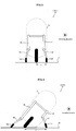
- FIG. 4 is a rear view illustrating a state of the vehicle 10 according to the embodiment of the present invention at turning.
- FIG. 4 illustrates a state where the vehicle 10 is turned to the right with a right rotation of the handle 41a.
- the wheel 12L connected to the second suspension arm 52 is moved to the left from its regular position as denoted by the dotted line of FIG. 2 such that the tread width between the wheels increases.
- the wheel 12L is configured to be steered by the fork 67, so that it is steered following the lean of the vehicle body 15, whereby the vehicle 10 can perform desired turning operation.
- the tread width between the wheels 12L and 12B is "a"
- the tread width between the wheels 12L and 12B is "b" which is larger than "a”. This makes it possible to avoid a situation where traveling at turning becomes unstable due to relatively smaller tread width as compared to the vehicle height of the vehicle 10.
- the second suspension arm 52 is connected to the first suspension arm 51 via the shock absorber 55, so that when the handle 41a is rotated for turning operation, the tread width increases with the second suspension arm 52 gently separated from the vehicle body 15 in the vehicle width direction.
- the second suspension arm 52 gently becomes close to the vehicle body 15 by attenuation effect of the shock absorber 55, whereby the tread width reduces.
- the wheels 12L and 12R each having the caster trail and the shock absorber 55 smoothly absorb a change caused due to increase/decrease in the tread width, whereby both turning performance and straight traveling performance can be improved.
- the tread width increases.
- the tread width increases as necessary, whereby traveling is stabilized, and the risk of overturning can be reduced.
Landscapes
- Engineering & Computer Science (AREA)
- Mechanical Engineering (AREA)
- Automatic Cycles, And Cycles In General (AREA)
- Steering Devices For Bicycles And Motorcycles (AREA)
- Axle Suspensions And Sidecars For Cycles (AREA)
- Vehicle Body Suspensions (AREA)
Abstract
Description
- The present invention relates to a vehicle having a vehicle body provided with three or more wheels including a steered wheel having a trail.
- In recent years, fuel saving for vehicles is strongly required in view of energy resource depletion problem. On the other hand, the number of vehicle owners is being increased due to reduction in price of vehicles, and there is a tendency that one person owns one vehicle. Thus, it is often the case that, for example, only one person (driver) rides in a 4-seater vehicle, causing energy to be wastefully consumed. In order to achieve fuel saving by miniaturization of a vehicle, designing a vehicle as a one-person vehicle with three or four wheels is most efficient.
- However, stability of such a vehicle may be deteriorated depending on a traveling state of the vehicle. In order to cope with this, there is proposed a technique in which a vehicle body is leaned laterally to improve stability of a vehicle at turning.
- Patent Document 1 (
JP 2013-71688A - In the vehicle described in Patent Document 1, the leaning angle of the vehicle body and the actual steering angle of the steered wheel are changed by a motor based on an input to the steering wheel and detected values of the vehicle speed sensor and lateral acceleration sensor, so that the actual steering angle can be stabilized even at a low speed, whereby stable traveling can be achieved in the whole vehicle speed region.
- However, when the height of a vehicle is relatively high as compared to the tread as in the vehicle described in Patent Document 1, traveling of a vehicle may become unstable.
- To solve the above problem, a vehicle according to the present invention includes a pair of first suspension arms, a pair of second suspension arms connected to the pair of first suspension arms via a pair of joints, a pair of attenuation devices that connect the pair of first suspension arms and the pair of second suspension arms, a pair of forks provided so as to allow turning about a steering axis with respect to the pair of second suspension arms, a pair of front wheels arranged on the pair of forks, a vehicle body to which the pair of front wheels are provided, and a leaning part for leaning the vehicle body. The tread width increases as the vehicle body is leaned by the leaning part.
- In the vehicle according to the present invention, as the vehicle body is leaned by the leaning part, the tread width increases . Thus, according to the vehicle of the present invention having such a configuration, the tread width increases as necessary, whereby traveling is stabilized, and the risk of overturning can be reduced.
-
-
FIG. 1 is a left side view of avehicle 10 according to an embodiment of the present invention; -
FIG. 2 is a top view of thevehicle 10 according to the embodiment of the present invention; -
FIG. 3 is a rear view of thevehicle 10 according to the embodiment of the present invention; and -
FIG. 4 is a rear view illustrating a state of thevehicle 10 according to the embodiment of the present invention at turning. - Hereinafter, an embodiment of the present invention will be described with reference to the drawings.
-
FIG. 1 is a left side view of avehicle 10 according to the embodiment of the present invention.FIG. 2 is a top view of thevehicle 10 according to the embodiment of the present invention.FIG. 3 is a rear view of thevehicle 10 according to the embodiment of the present invention. - In the drawings, the
reference numeral 10 denotes a vehicle employed in the present embodiment. Thevehicle 10 has a drive part (not illustrated) of avehicle body 15, acabin part 11 in which an occupant sits and steers the vehicle, left andright wheels wheel 12B, which is a rear wheel disposed at the rear of the vehicle body and at the width direction center thereof and serves as a driven wheel and a non-steered wheel not being capable of being steered. - The
vehicle 10 further has a leaning mechanism (not illustrated) for leaning thevehicle body 15 to the left and right, i.e., a vehicle body leaning mechanism that leans suspension arms supporting the respective left andright wheels vehicle body 15. - Basically, in the
vehicle 10 according to the present invention, thevehicle 10 is turned by changing the leaning angle of thevehicle body 15. That is, in thevehicle 10, thevehicle body 15 including thecabin part 11 is leaned to the turning inner wheel side to thereby improve turning performance and secure comfortability for the occupant. - That is, in the
vehicle 10, thevehicle body 15 can be leaned laterally (left-right direction). In the example illustrated inFIG. 3 , the left andright wheels road surface 18. - A
seat 11a in thecabin part 11 is a part on which the occupant sits during traveling of thevehicle 10. Afootrest 11b is a part for supporting the foot of the occupant and is provided at the lower part of the front side (right side inFIG. 1 ) of theseat 11a. - A battery device (not illustrated) is provided rearward or downward of the
cabin part 11. The battery device serves as an energy supply source for a rotary driving device or the like that drives the drivenwheel 12B into rotation. Further, a controller (not illustrated), an inverter device, various sensors, and the like are provided rearward or downward of thecabin part 11. - A
maneuvering device 41 is provided forward of theseat 11a. Themaneuvering device 41 is provided with members required for maneuvering, such as ahandle 41a serving as a steering device that the occupant operates to input steering command information such as a steering direction, steering angle, or the like, a meter such as a speed meter, an indicator, and a switch. - The occupant operates the
handle 41a and other members to give instructions as to the traveling state (e.g., traveling direction, traveling speed, turning direction, and turning radius) of thevehicle 10. As the steering device, a device such as a steering wheel, a jog dial, a touch panel, or a push button may be used in place of thehandle 41a. - The
wheels second suspension arms 52, respectively, via a pair offorks 67 constituting a part of a suspension device. The left andright forks 67 are fixed to the pair ofsecond suspension arms 52, respectively, so as to be each turnable about asteering axis 66. - The
second suspension arm 52 is connected to thefirst suspension arm 51 via a joint 54. The joint 54 connects thesecond suspension arm 52 andfirst suspension arm 51 such that they can be turned with respect to each other about aturning axis 53. - Further, the
first suspension arm 51 and thesecond suspension arm 52 are connected to each other by a shock absorber 55 as an attenuation device, in addition to the joint 54. Theshock absorber 55 is illustrated schematically only inFIG. 1 and omitted in other drawings. - A predetermined trail LT exists between an intersection P between the
steering axis 66 of thewheel right wheels wheels vehicle 10 according to the preset embodiment, the intersection P between (the extension line of) thesteering axis 66 of each of thewheels - The turning of each of the
wheels wheels vehicle 10, but to motion of each of thewheels steering axis 66 thereof. - The
handle 41a is connected to the upper end of a steering axis member (not illustrated), and the upper end of the steering axis member is rotatably fixed to a frame member (not illustrated) provided in thecabin part 11. - A rotation angle of the upper end of the steering axis member with respect to the frame member, i.e., a handle angle as a steering angle command value that the occupant inputs by operating the
handle 41a is detected by a handle operation angle sensor (not illustrated) as an input steering angle detection means. The handle operation angle sensor is e.g., an encoder. - In the
vehicle 10 according to the present invention, a lean angle is determined based on a handle angle detected by the handle operation angle sensor and a vehicle speed detected by a vehicle speed sensor. Then, thevehicle body 15 is leaned based on the determined lean angle by a vehicle body leaning mechanism (not illustrated) to thereby turn thevehicle 10. - When the distance between the
wheels vehicle 10, traveling of thevehicle 10 may become unstable. Thus, at turning, thevehicle 10 according to the present invention performs such an operation as to increase the tread width so as to reduce the possibility of unstable traveling. -
FIG. 4 is a rear view illustrating a state of thevehicle 10 according to the embodiment of the present invention at turning.FIG. 4 illustrates a state where thevehicle 10 is turned to the right with a right rotation of thehandle 41a. At this time, in thevehicle 10 according to the present invention, thewheel 12L connected to thesecond suspension arm 52 is moved to the left from its regular position as denoted by the dotted line ofFIG. 2 such that the tread width between the wheels increases. Further, thewheel 12L is configured to be steered by thefork 67, so that it is steered following the lean of thevehicle body 15, whereby thevehicle 10 can perform desired turning operation. - In an upright state of the
vehicle body 15 illustrated inFIG. 3 , the tread width between thewheels vehicle body 15 illustrated inFIG. 4 , the tread width between thewheels vehicle 10. - The
second suspension arm 52 is connected to thefirst suspension arm 51 via theshock absorber 55, so that when thehandle 41a is rotated for turning operation, the tread width increases with thesecond suspension arm 52 gently separated from thevehicle body 15 in the vehicle width direction. - Further, also when the
handle 41a is turned for switching from the turning state to a straight traveling state to return thevehicle body 10 from the leaned state to upright state, thesecond suspension arm 52 gently becomes close to thevehicle body 15 by attenuation effect of theshock absorber 55, whereby the tread width reduces. - In the
vehicle 10 according to the present invention, when thevehicle body 15 is leaned to change the tread width, thewheels shock absorber 55 smoothly absorb a change caused due to increase/decrease in the tread width, whereby both turning performance and straight traveling performance can be improved. - As described above, in the
vehicle 10 according to the present invention, as thevehicle body 15 is leaned by the vehicle body leaning mechanism (leaning part), the tread width increases. Thus, according to thevehicle 10 of the present invention having such a configuration, the tread width increases as necessary, whereby traveling is stabilized, and the risk of overturning can be reduced. - In recent years, various efforts have been made to cope with energy problems by designing a vehicle as a small-size vehicle such as a one-person vehicle with three or four wheels. Conventionally, in such a small-size vehicle, the vehicle height is relatively larger as compared to the tread, which may make traveling unstable. On the other hand, in the vehicle according to the present invention, as the vehicle body is leaned by the leaning part, the tread width increases. Thus, according to the vehicle of the present invention having such a configuration, the tread width increases as necessary, whereby traveling is stabilized, and the risk of overturning can be reduced, and thus, the industrial applicability is very high.
-
- 10: Vehicle
- 11: Cabin part
- 11a: Seat
- 11b: Footrest
- 15: Vehicle body
- 12B: Wheel
- 12R: Wheel
- 12L: Wheel
- 41a: Handle
- 51: First suspension arm
- 52: Second suspension arm
- 53: Turning axis
- 54: Joint
- 55: Shock absorber (attenuation device)
- 66: Steering axis
- 67: Fork
Claims (1)
- A vehicle characterized by comprising:a pair of first suspension arms;a pair of second suspension arms connected to the pair of first suspension arms via a pair of joints;a pair of attenuation devices that connect the pair of first suspension arms and the pair of second suspension arms;a pair of forks provided so as to allow turning about a steering axis with respect to the pair of second suspension arms;a pair of front wheels arranged on the pair of forks;a vehicle body to which the pair of front wheels are provided; anda leaning part for leaning the vehicle body, whereinthe tread width increases as the vehicle body is leaned by the leaning part.
Applications Claiming Priority (2)
| Application Number | Priority Date | Filing Date | Title |
|---|---|---|---|
| JP2016071392A JP6722916B2 (en) | 2016-03-31 | 2016-03-31 | vehicle |
| PCT/JP2017/010516 WO2017169806A1 (en) | 2016-03-31 | 2017-03-15 | Vehicle |
Publications (3)
| Publication Number | Publication Date |
|---|---|
| EP3437973A1 true EP3437973A1 (en) | 2019-02-06 |
| EP3437973A4 EP3437973A4 (en) | 2019-12-11 |
| EP3437973B1 EP3437973B1 (en) | 2023-06-07 |
Family
ID=59965254
Family Applications (1)
| Application Number | Title | Priority Date | Filing Date |
|---|---|---|---|
| EP17774350.7A Active EP3437973B1 (en) | 2016-03-31 | 2017-03-15 | Vehicle |
Country Status (5)
| Country | Link |
|---|---|
| US (1) | US10421516B2 (en) |
| EP (1) | EP3437973B1 (en) |
| JP (1) | JP6722916B2 (en) |
| CN (1) | CN108025783A (en) |
| WO (1) | WO2017169806A1 (en) |
Families Citing this family (1)
| Publication number | Priority date | Publication date | Assignee | Title |
|---|---|---|---|---|
| JP2018127140A (en) * | 2017-02-09 | 2018-08-16 | トヨタ自動車株式会社 | Auto tilt vehicle |
Family Cites Families (20)
| Publication number | Priority date | Publication date | Assignee | Title |
|---|---|---|---|---|
| IT1124375B (en) * | 1979-12-07 | 1986-05-07 | Valentino Ribi | ARTICULATED QUADRILATERAL SUSPENSION WITH AT LEAST ONE SHOCK ABSORBER FOR VEHICLE WHEELS, IN PARTICULAR OF MOTORCYCLES |
| US4887829A (en) * | 1987-04-07 | 1989-12-19 | Prince Curtis L | Rear wheel suspension system for a tricycle vehicle |
| JPH06312613A (en) * | 1993-04-30 | 1994-11-08 | Mazda Motor Corp | Suspension |
| US5810383A (en) | 1996-12-23 | 1998-09-22 | Anderson; Carey C. | Suspension and steering linkage for a tricycle |
| GB2374327A (en) * | 2001-03-27 | 2002-10-16 | Andrew Felipe Trujillo | Laterally tilting vehicle |
| US20060071440A1 (en) * | 2004-09-29 | 2006-04-06 | Fought Gerald E | Mid drive scooter |
| JP2007153024A (en) * | 2005-12-01 | 2007-06-21 | Equos Research Co Ltd | vehicle |
| EP1884457B1 (en) * | 2006-07-26 | 2009-09-23 | Yamaha Motor Europe N.V. | Motorcycle |
| CN101537866A (en) | 2008-03-19 | 2009-09-23 | 王立扬 | Front suspension and steering system for bicycles and motorcycles with front wheels that do not tip over |
| GB2461081B (en) * | 2008-06-19 | 2011-12-28 | Gibbs Tech Ltd | A three-wheeled amphibian with retractable wheels |
| JP5181941B2 (en) * | 2008-09-04 | 2013-04-10 | 株式会社エクォス・リサーチ | vehicle |
| CN102458972A (en) | 2009-04-10 | 2012-05-16 | 爱考斯研究株式会社 | vehicle |
| CN102092435B (en) | 2009-12-10 | 2014-11-05 | 光阳工业股份有限公司 | Anti-tipping device for vehicles with two front wheels |
| GB2480639B (en) | 2010-05-26 | 2012-04-25 | Adiva Co Ltd | Suspension for a tricycle |
| US8485541B2 (en) | 2010-06-03 | 2013-07-16 | Nicola Pozio | Suspension for a tricycle |
| US8973695B2 (en) * | 2010-06-15 | 2015-03-10 | Eyal Jacob Aloni | Vehicle wheeled device |
| JP2013071688A (en) | 2011-09-29 | 2013-04-22 | Equos Research Co Ltd | vehicle |
| JP5890722B2 (en) | 2012-03-30 | 2016-03-22 | Kyb株式会社 | Suspension device |
| JP2013233895A (en) * | 2012-05-10 | 2013-11-21 | Jtekt Corp | Vehicle |
| JP6043274B2 (en) * | 2013-12-20 | 2016-12-14 | 本田技研工業株式会社 | Front two-wheel saddle-type swing vehicle |
-
2016
- 2016-03-31 JP JP2016071392A patent/JP6722916B2/en active Active
-
2017
- 2017-03-15 US US15/763,388 patent/US10421516B2/en active Active
- 2017-03-15 EP EP17774350.7A patent/EP3437973B1/en active Active
- 2017-03-15 WO PCT/JP2017/010516 patent/WO2017169806A1/en not_active Ceased
- 2017-03-15 CN CN201780003173.0A patent/CN108025783A/en active Pending
Also Published As
| Publication number | Publication date |
|---|---|
| US10421516B2 (en) | 2019-09-24 |
| EP3437973B1 (en) | 2023-06-07 |
| US20180281887A1 (en) | 2018-10-04 |
| EP3437973A4 (en) | 2019-12-11 |
| CN108025783A (en) | 2018-05-11 |
| JP6722916B2 (en) | 2020-07-15 |
| JP2017178186A (en) | 2017-10-05 |
| WO2017169806A1 (en) | 2017-10-05 |
Similar Documents
| Publication | Publication Date | Title |
|---|---|---|
| JP6646682B2 (en) | Lean vehicle | |
| EP3300999B1 (en) | Rocking control device for two front wheels rocking vehicle | |
| EP3301000B1 (en) | Rocking control device for two front wheels rocking vehicle | |
| JP5784420B2 (en) | Sheet device | |
| CN107074318B (en) | vehicle | |
| WO2013031796A1 (en) | Seat apparatus | |
| JP5369999B2 (en) | vehicle | |
| JP6603953B2 (en) | vehicle | |
| WO2020138395A1 (en) | Inclining vehicle equipped with steerable front wheel | |
| WO2018181750A1 (en) | Vehicle | |
| JP5458723B2 (en) | vehicle | |
| JP2014133480A (en) | Work machine | |
| EP3437973B1 (en) | Vehicle | |
| JP2017178188A (en) | vehicle | |
| JP3384725B2 (en) | Reach type forklift | |
| JP6237444B2 (en) | Industrial vehicle | |
| JP2007153024A (en) | vehicle | |
| JP2011046275A (en) | Vehicle | |
| JP5440299B2 (en) | vehicle | |
| JP2002284048A (en) | Electric car | |
| JP2018134969A (en) | Vehicle equipped with a lean mechanism | |
| WO2016143471A1 (en) | Vehicle | |
| JP6265143B2 (en) | Balance training system | |
| JP2022068906A (en) | vehicle | |
| JP2001287682A (en) | Riding equipment |
Legal Events
| Date | Code | Title | Description |
|---|---|---|---|
| STAA | Information on the status of an ep patent application or granted ep patent |
Free format text: STATUS: THE INTERNATIONAL PUBLICATION HAS BEEN MADE |
|
| PUAI | Public reference made under article 153(3) epc to a published international application that has entered the european phase |
Free format text: ORIGINAL CODE: 0009012 |
|
| STAA | Information on the status of an ep patent application or granted ep patent |
Free format text: STATUS: REQUEST FOR EXAMINATION WAS MADE |
|
| 17P | Request for examination filed |
Effective date: 20180813 |
|
| AK | Designated contracting states |
Kind code of ref document: A1 Designated state(s): AL AT BE BG CH CY CZ DE DK EE ES FI FR GB GR HR HU IE IS IT LI LT LU LV MC MK MT NL NO PL PT RO RS SE SI SK SM TR |
|
| AX | Request for extension of the european patent |
Extension state: BA ME |
|
| DAV | Request for validation of the european patent (deleted) | ||
| DAX | Request for extension of the european patent (deleted) | ||
| A4 | Supplementary search report drawn up and despatched |
Effective date: 20191112 |
|
| RIC1 | Information provided on ipc code assigned before grant |
Ipc: B62K 5/05 20130101ALI20191106BHEP Ipc: B62K 5/10 20130101AFI20191106BHEP Ipc: B62K 5/08 20060101ALI20191106BHEP Ipc: B62K 5/00 20130101ALI20191106BHEP Ipc: B62K 25/24 20060101ALI20191106BHEP |
|
| RAP1 | Party data changed (applicant data changed or rights of an application transferred) |
Owner name: AISIN CORPORATION |
|
| STAA | Information on the status of an ep patent application or granted ep patent |
Free format text: STATUS: EXAMINATION IS IN PROGRESS |
|
| 17Q | First examination report despatched |
Effective date: 20220615 |
|
| GRAP | Despatch of communication of intention to grant a patent |
Free format text: ORIGINAL CODE: EPIDOSNIGR1 |
|
| STAA | Information on the status of an ep patent application or granted ep patent |
Free format text: STATUS: GRANT OF PATENT IS INTENDED |
|
| INTG | Intention to grant announced |
Effective date: 20230112 |
|
| GRAS | Grant fee paid |
Free format text: ORIGINAL CODE: EPIDOSNIGR3 |
|
| GRAA | (expected) grant |
Free format text: ORIGINAL CODE: 0009210 |
|
| STAA | Information on the status of an ep patent application or granted ep patent |
Free format text: STATUS: THE PATENT HAS BEEN GRANTED |
|
| AK | Designated contracting states |
Kind code of ref document: B1 Designated state(s): AL AT BE BG CH CY CZ DE DK EE ES FI FR GB GR HR HU IE IS IT LI LT LU LV MC MK MT NL NO PL PT RO RS SE SI SK SM TR |
|
| REG | Reference to a national code |
Ref country code: GB Ref legal event code: FG4D |
|
| REG | Reference to a national code |
Ref country code: CH Ref legal event code: EP Ref country code: AT Ref legal event code: REF Ref document number: 1574214 Country of ref document: AT Kind code of ref document: T Effective date: 20230615 Ref country code: DE Ref legal event code: R096 Ref document number: 602017069661 Country of ref document: DE |
|
| REG | Reference to a national code |
Ref country code: LT Ref legal event code: MG9D |
|
| REG | Reference to a national code |
Ref country code: NL Ref legal event code: MP Effective date: 20230607 |
|
| PG25 | Lapsed in a contracting state [announced via postgrant information from national office to epo] |
Ref country code: SE Free format text: LAPSE BECAUSE OF FAILURE TO SUBMIT A TRANSLATION OF THE DESCRIPTION OR TO PAY THE FEE WITHIN THE PRESCRIBED TIME-LIMIT Effective date: 20230607 Ref country code: NO Free format text: LAPSE BECAUSE OF FAILURE TO SUBMIT A TRANSLATION OF THE DESCRIPTION OR TO PAY THE FEE WITHIN THE PRESCRIBED TIME-LIMIT Effective date: 20230907 Ref country code: ES Free format text: LAPSE BECAUSE OF FAILURE TO SUBMIT A TRANSLATION OF THE DESCRIPTION OR TO PAY THE FEE WITHIN THE PRESCRIBED TIME-LIMIT Effective date: 20230607 |
|
| REG | Reference to a national code |
Ref country code: AT Ref legal event code: MK05 Ref document number: 1574214 Country of ref document: AT Kind code of ref document: T Effective date: 20230607 |
|
| PG25 | Lapsed in a contracting state [announced via postgrant information from national office to epo] |
Ref country code: RS Free format text: LAPSE BECAUSE OF FAILURE TO SUBMIT A TRANSLATION OF THE DESCRIPTION OR TO PAY THE FEE WITHIN THE PRESCRIBED TIME-LIMIT Effective date: 20230607 Ref country code: NL Free format text: LAPSE BECAUSE OF FAILURE TO SUBMIT A TRANSLATION OF THE DESCRIPTION OR TO PAY THE FEE WITHIN THE PRESCRIBED TIME-LIMIT Effective date: 20230607 Ref country code: LV Free format text: LAPSE BECAUSE OF FAILURE TO SUBMIT A TRANSLATION OF THE DESCRIPTION OR TO PAY THE FEE WITHIN THE PRESCRIBED TIME-LIMIT Effective date: 20230607 Ref country code: LT Free format text: LAPSE BECAUSE OF FAILURE TO SUBMIT A TRANSLATION OF THE DESCRIPTION OR TO PAY THE FEE WITHIN THE PRESCRIBED TIME-LIMIT Effective date: 20230607 Ref country code: HR Free format text: LAPSE BECAUSE OF FAILURE TO SUBMIT A TRANSLATION OF THE DESCRIPTION OR TO PAY THE FEE WITHIN THE PRESCRIBED TIME-LIMIT Effective date: 20230607 Ref country code: GR Free format text: LAPSE BECAUSE OF FAILURE TO SUBMIT A TRANSLATION OF THE DESCRIPTION OR TO PAY THE FEE WITHIN THE PRESCRIBED TIME-LIMIT Effective date: 20230908 |
|
| PG25 | Lapsed in a contracting state [announced via postgrant information from national office to epo] |
Ref country code: FI Free format text: LAPSE BECAUSE OF FAILURE TO SUBMIT A TRANSLATION OF THE DESCRIPTION OR TO PAY THE FEE WITHIN THE PRESCRIBED TIME-LIMIT Effective date: 20230607 |
|
| PG25 | Lapsed in a contracting state [announced via postgrant information from national office to epo] |
Ref country code: SK Free format text: LAPSE BECAUSE OF FAILURE TO SUBMIT A TRANSLATION OF THE DESCRIPTION OR TO PAY THE FEE WITHIN THE PRESCRIBED TIME-LIMIT Effective date: 20230607 |
|
| PG25 | Lapsed in a contracting state [announced via postgrant information from national office to epo] |
Ref country code: IS Free format text: LAPSE BECAUSE OF FAILURE TO SUBMIT A TRANSLATION OF THE DESCRIPTION OR TO PAY THE FEE WITHIN THE PRESCRIBED TIME-LIMIT Effective date: 20231007 |
|
| PG25 | Lapsed in a contracting state [announced via postgrant information from national office to epo] |
Ref country code: SM Free format text: LAPSE BECAUSE OF FAILURE TO SUBMIT A TRANSLATION OF THE DESCRIPTION OR TO PAY THE FEE WITHIN THE PRESCRIBED TIME-LIMIT Effective date: 20230607 Ref country code: SK Free format text: LAPSE BECAUSE OF FAILURE TO SUBMIT A TRANSLATION OF THE DESCRIPTION OR TO PAY THE FEE WITHIN THE PRESCRIBED TIME-LIMIT Effective date: 20230607 Ref country code: RO Free format text: LAPSE BECAUSE OF FAILURE TO SUBMIT A TRANSLATION OF THE DESCRIPTION OR TO PAY THE FEE WITHIN THE PRESCRIBED TIME-LIMIT Effective date: 20230607 Ref country code: PT Free format text: LAPSE BECAUSE OF FAILURE TO SUBMIT A TRANSLATION OF THE DESCRIPTION OR TO PAY THE FEE WITHIN THE PRESCRIBED TIME-LIMIT Effective date: 20231009 Ref country code: IS Free format text: LAPSE BECAUSE OF FAILURE TO SUBMIT A TRANSLATION OF THE DESCRIPTION OR TO PAY THE FEE WITHIN THE PRESCRIBED TIME-LIMIT Effective date: 20231007 Ref country code: EE Free format text: LAPSE BECAUSE OF FAILURE TO SUBMIT A TRANSLATION OF THE DESCRIPTION OR TO PAY THE FEE WITHIN THE PRESCRIBED TIME-LIMIT Effective date: 20230607 Ref country code: CZ Free format text: LAPSE BECAUSE OF FAILURE TO SUBMIT A TRANSLATION OF THE DESCRIPTION OR TO PAY THE FEE WITHIN THE PRESCRIBED TIME-LIMIT Effective date: 20230607 Ref country code: AT Free format text: LAPSE BECAUSE OF FAILURE TO SUBMIT A TRANSLATION OF THE DESCRIPTION OR TO PAY THE FEE WITHIN THE PRESCRIBED TIME-LIMIT Effective date: 20230607 |
|
| PG25 | Lapsed in a contracting state [announced via postgrant information from national office to epo] |
Ref country code: PL Free format text: LAPSE BECAUSE OF FAILURE TO SUBMIT A TRANSLATION OF THE DESCRIPTION OR TO PAY THE FEE WITHIN THE PRESCRIBED TIME-LIMIT Effective date: 20230607 |
|
| REG | Reference to a national code |
Ref country code: DE Ref legal event code: R097 Ref document number: 602017069661 Country of ref document: DE |
|
| PLBE | No opposition filed within time limit |
Free format text: ORIGINAL CODE: 0009261 |
|
| STAA | Information on the status of an ep patent application or granted ep patent |
Free format text: STATUS: NO OPPOSITION FILED WITHIN TIME LIMIT |
|
| PG25 | Lapsed in a contracting state [announced via postgrant information from national office to epo] |
Ref country code: DK Free format text: LAPSE BECAUSE OF FAILURE TO SUBMIT A TRANSLATION OF THE DESCRIPTION OR TO PAY THE FEE WITHIN THE PRESCRIBED TIME-LIMIT Effective date: 20230607 |
|
| PG25 | Lapsed in a contracting state [announced via postgrant information from national office to epo] |
Ref country code: SI Free format text: LAPSE BECAUSE OF FAILURE TO SUBMIT A TRANSLATION OF THE DESCRIPTION OR TO PAY THE FEE WITHIN THE PRESCRIBED TIME-LIMIT Effective date: 20230607 |
|
| 26N | No opposition filed |
Effective date: 20240308 |
|
| PG25 | Lapsed in a contracting state [announced via postgrant information from national office to epo] |
Ref country code: SI Free format text: LAPSE BECAUSE OF FAILURE TO SUBMIT A TRANSLATION OF THE DESCRIPTION OR TO PAY THE FEE WITHIN THE PRESCRIBED TIME-LIMIT Effective date: 20230607 Ref country code: IT Free format text: LAPSE BECAUSE OF FAILURE TO SUBMIT A TRANSLATION OF THE DESCRIPTION OR TO PAY THE FEE WITHIN THE PRESCRIBED TIME-LIMIT Effective date: 20230607 |
|
| REG | Reference to a national code |
Ref country code: CH Ref legal event code: PL |
|
| PG25 | Lapsed in a contracting state [announced via postgrant information from national office to epo] |
Ref country code: BG Free format text: LAPSE BECAUSE OF FAILURE TO SUBMIT A TRANSLATION OF THE DESCRIPTION OR TO PAY THE FEE WITHIN THE PRESCRIBED TIME-LIMIT Effective date: 20230607 |
|
| PG25 | Lapsed in a contracting state [announced via postgrant information from national office to epo] |
Ref country code: LU Free format text: LAPSE BECAUSE OF NON-PAYMENT OF DUE FEES Effective date: 20240315 |
|
| PG25 | Lapsed in a contracting state [announced via postgrant information from national office to epo] |
Ref country code: MC Free format text: LAPSE BECAUSE OF FAILURE TO SUBMIT A TRANSLATION OF THE DESCRIPTION OR TO PAY THE FEE WITHIN THE PRESCRIBED TIME-LIMIT Effective date: 20230607 |
|
| GBPC | Gb: european patent ceased through non-payment of renewal fee |
Effective date: 20240315 |
|
| PG25 | Lapsed in a contracting state [announced via postgrant information from national office to epo] |
Ref country code: MC Free format text: LAPSE BECAUSE OF FAILURE TO SUBMIT A TRANSLATION OF THE DESCRIPTION OR TO PAY THE FEE WITHIN THE PRESCRIBED TIME-LIMIT Effective date: 20230607 Ref country code: LU Free format text: LAPSE BECAUSE OF NON-PAYMENT OF DUE FEES Effective date: 20240315 Ref country code: BG Free format text: LAPSE BECAUSE OF FAILURE TO SUBMIT A TRANSLATION OF THE DESCRIPTION OR TO PAY THE FEE WITHIN THE PRESCRIBED TIME-LIMIT Effective date: 20230607 |
|
| REG | Reference to a national code |
Ref country code: BE Ref legal event code: MM Effective date: 20240331 |
|
| PG25 | Lapsed in a contracting state [announced via postgrant information from national office to epo] |
Ref country code: BE Free format text: LAPSE BECAUSE OF NON-PAYMENT OF DUE FEES Effective date: 20240331 |
|
| PG25 | Lapsed in a contracting state [announced via postgrant information from national office to epo] |
Ref country code: GB Free format text: LAPSE BECAUSE OF NON-PAYMENT OF DUE FEES Effective date: 20240315 |
|
| PG25 | Lapsed in a contracting state [announced via postgrant information from national office to epo] |
Ref country code: FR Free format text: LAPSE BECAUSE OF NON-PAYMENT OF DUE FEES Effective date: 20240331 |
|
| PG25 | Lapsed in a contracting state [announced via postgrant information from national office to epo] |
Ref country code: IE Free format text: LAPSE BECAUSE OF NON-PAYMENT OF DUE FEES Effective date: 20240315 |
|
| PG25 | Lapsed in a contracting state [announced via postgrant information from national office to epo] |
Ref country code: IE Free format text: LAPSE BECAUSE OF NON-PAYMENT OF DUE FEES Effective date: 20240315 Ref country code: GB Free format text: LAPSE BECAUSE OF NON-PAYMENT OF DUE FEES Effective date: 20240315 Ref country code: FR Free format text: LAPSE BECAUSE OF NON-PAYMENT OF DUE FEES Effective date: 20240331 Ref country code: BE Free format text: LAPSE BECAUSE OF NON-PAYMENT OF DUE FEES Effective date: 20240331 Ref country code: CH Free format text: LAPSE BECAUSE OF NON-PAYMENT OF DUE FEES Effective date: 20240331 |
|
| PG25 | Lapsed in a contracting state [announced via postgrant information from national office to epo] |
Ref country code: CY Free format text: LAPSE BECAUSE OF FAILURE TO SUBMIT A TRANSLATION OF THE DESCRIPTION OR TO PAY THE FEE WITHIN THE PRESCRIBED TIME-LIMIT; INVALID AB INITIO Effective date: 20170315 |
|
| PG25 | Lapsed in a contracting state [announced via postgrant information from national office to epo] |
Ref country code: HU Free format text: LAPSE BECAUSE OF FAILURE TO SUBMIT A TRANSLATION OF THE DESCRIPTION OR TO PAY THE FEE WITHIN THE PRESCRIBED TIME-LIMIT; INVALID AB INITIO Effective date: 20170315 |
|
| PG25 | Lapsed in a contracting state [announced via postgrant information from national office to epo] |
Ref country code: TR Free format text: LAPSE BECAUSE OF FAILURE TO SUBMIT A TRANSLATION OF THE DESCRIPTION OR TO PAY THE FEE WITHIN THE PRESCRIBED TIME-LIMIT Effective date: 20230607 |
|
| PGFP | Annual fee paid to national office [announced via postgrant information from national office to epo] |
Ref country code: DE Payment date: 20260128 Year of fee payment: 10 |