EP3437862B1 - Controlling application of forces to different portions of object surface using bladder - Google Patents
Controlling application of forces to different portions of object surface using bladder Download PDFInfo
- Publication number
- EP3437862B1 EP3437862B1 EP18185665.9A EP18185665A EP3437862B1 EP 3437862 B1 EP3437862 B1 EP 3437862B1 EP 18185665 A EP18185665 A EP 18185665A EP 3437862 B1 EP3437862 B1 EP 3437862B1
- Authority
- EP
- European Patent Office
- Prior art keywords
- force
- pressure
- contact member
- flexible wall
- bladder
- Prior art date
- Legal status (The legal status is an assumption and is not a legal conclusion. Google has not performed a legal analysis and makes no representation as to the accuracy of the status listed.)
- Active
Links
- 238000000034 method Methods 0.000 claims description 39
- 239000012530 fluid Substances 0.000 claims description 30
- 230000006835 compression Effects 0.000 claims description 7
- 238000007906 compression Methods 0.000 claims description 7
- 239000013598 vector Substances 0.000 claims description 7
- 238000012545 processing Methods 0.000 description 13
- 239000002131 composite material Substances 0.000 description 6
- 230000008569 process Effects 0.000 description 6
- 230000008859 change Effects 0.000 description 5
- 238000003825 pressing Methods 0.000 description 4
- 238000007789 sealing Methods 0.000 description 4
- 239000007788 liquid Substances 0.000 description 3
- 239000012528 membrane Substances 0.000 description 3
- 238000013459 approach Methods 0.000 description 2
- 238000013461 design Methods 0.000 description 2
- 239000006260 foam Substances 0.000 description 2
- 239000002184 metal Substances 0.000 description 2
- 238000005086 pumping Methods 0.000 description 2
- 238000007493 shaping process Methods 0.000 description 2
- 230000000007 visual effect Effects 0.000 description 2
- 230000008901 benefit Effects 0.000 description 1
- 230000000295 complement effect Effects 0.000 description 1
- 238000007596 consolidation process Methods 0.000 description 1
- 230000007812 deficiency Effects 0.000 description 1
- 230000004069 differentiation Effects 0.000 description 1
- 230000000694 effects Effects 0.000 description 1
- 239000013536 elastomeric material Substances 0.000 description 1
- 239000000835 fiber Substances 0.000 description 1
- 239000011888 foil Substances 0.000 description 1
- 238000010438 heat treatment Methods 0.000 description 1
- 238000007731 hot pressing Methods 0.000 description 1
- 238000012986 modification Methods 0.000 description 1
- 230000004048 modification Effects 0.000 description 1
- 230000035699 permeability Effects 0.000 description 1
- 229920000642 polymer Polymers 0.000 description 1
- 238000011112 process operation Methods 0.000 description 1
- 230000008439 repair process Effects 0.000 description 1
- 238000010008 shearing Methods 0.000 description 1
- 239000000758 substrate Substances 0.000 description 1
- 230000007704 transition Effects 0.000 description 1
Images


Classifications
-
- B—PERFORMING OPERATIONS; TRANSPORTING
- B30—PRESSES
- B30B—PRESSES IN GENERAL
- B30B5/00—Presses characterised by the use of pressing means other than those mentioned in the preceding groups
- B30B5/02—Presses characterised by the use of pressing means other than those mentioned in the preceding groups wherein the pressing means is in the form of a flexible element, e.g. diaphragm, urged by fluid pressure
-
- B—PERFORMING OPERATIONS; TRANSPORTING
- B29—WORKING OF PLASTICS; WORKING OF SUBSTANCES IN A PLASTIC STATE IN GENERAL
- B29C—SHAPING OR JOINING OF PLASTICS; SHAPING OF MATERIAL IN A PLASTIC STATE, NOT OTHERWISE PROVIDED FOR; AFTER-TREATMENT OF THE SHAPED PRODUCTS, e.g. REPAIRING
- B29C66/00—General aspects of processes or apparatus for joining preformed parts
- B29C66/90—Measuring or controlling the joining process
- B29C66/92—Measuring or controlling the joining process by measuring or controlling the pressure, the force, the mechanical power or the displacement of the joining tools
- B29C66/924—Measuring or controlling the joining process by measuring or controlling the pressure, the force, the mechanical power or the displacement of the joining tools by controlling or regulating the pressure, the force, the mechanical power or the displacement of the joining tools
- B29C66/9241—Measuring or controlling the joining process by measuring or controlling the pressure, the force, the mechanical power or the displacement of the joining tools by controlling or regulating the pressure, the force, the mechanical power or the displacement of the joining tools by controlling or regulating the pressure, the force or the mechanical power
-
- B—PERFORMING OPERATIONS; TRANSPORTING
- B29—WORKING OF PLASTICS; WORKING OF SUBSTANCES IN A PLASTIC STATE IN GENERAL
- B29C—SHAPING OR JOINING OF PLASTICS; SHAPING OF MATERIAL IN A PLASTIC STATE, NOT OTHERWISE PROVIDED FOR; AFTER-TREATMENT OF THE SHAPED PRODUCTS, e.g. REPAIRING
- B29C70/00—Shaping composites, i.e. plastics material comprising reinforcements, fillers or preformed parts, e.g. inserts
- B29C70/04—Shaping composites, i.e. plastics material comprising reinforcements, fillers or preformed parts, e.g. inserts comprising reinforcements only, e.g. self-reinforcing plastics
- B29C70/28—Shaping operations therefor
- B29C70/40—Shaping or impregnating by compression not applied
- B29C70/42—Shaping or impregnating by compression not applied for producing articles of definite length, i.e. discrete articles
- B29C70/44—Shaping or impregnating by compression not applied for producing articles of definite length, i.e. discrete articles using isostatic pressure, e.g. pressure difference-moulding, vacuum bag-moulding, autoclave-moulding or expanding rubber-moulding
-
- B—PERFORMING OPERATIONS; TRANSPORTING
- B29—WORKING OF PLASTICS; WORKING OF SUBSTANCES IN A PLASTIC STATE IN GENERAL
- B29C—SHAPING OR JOINING OF PLASTICS; SHAPING OF MATERIAL IN A PLASTIC STATE, NOT OTHERWISE PROVIDED FOR; AFTER-TREATMENT OF THE SHAPED PRODUCTS, e.g. REPAIRING
- B29C65/00—Joining or sealing of preformed parts, e.g. welding of plastics materials; Apparatus therefor
- B29C65/56—Joining or sealing of preformed parts, e.g. welding of plastics materials; Apparatus therefor using mechanical means or mechanical connections, e.g. form-fits
-
- B—PERFORMING OPERATIONS; TRANSPORTING
- B29—WORKING OF PLASTICS; WORKING OF SUBSTANCES IN A PLASTIC STATE IN GENERAL
- B29C—SHAPING OR JOINING OF PLASTICS; SHAPING OF MATERIAL IN A PLASTIC STATE, NOT OTHERWISE PROVIDED FOR; AFTER-TREATMENT OF THE SHAPED PRODUCTS, e.g. REPAIRING
- B29C66/00—General aspects of processes or apparatus for joining preformed parts
- B29C66/001—Joining in special atmospheres
- B29C66/0012—Joining in special atmospheres characterised by the type of environment
- B29C66/0014—Gaseous environments
- B29C66/00145—Vacuum, e.g. partial vacuum
-
- B—PERFORMING OPERATIONS; TRANSPORTING
- B29—WORKING OF PLASTICS; WORKING OF SUBSTANCES IN A PLASTIC STATE IN GENERAL
- B29C—SHAPING OR JOINING OF PLASTICS; SHAPING OF MATERIAL IN A PLASTIC STATE, NOT OTHERWISE PROVIDED FOR; AFTER-TREATMENT OF THE SHAPED PRODUCTS, e.g. REPAIRING
- B29C66/00—General aspects of processes or apparatus for joining preformed parts
- B29C66/80—General aspects of machine operations or constructions and parts thereof
- B29C66/81—General aspects of the pressing elements, i.e. the elements applying pressure on the parts to be joined in the area to be joined, e.g. the welding jaws or clamps
- B29C66/814—General aspects of the pressing elements, i.e. the elements applying pressure on the parts to be joined in the area to be joined, e.g. the welding jaws or clamps characterised by the design of the pressing elements, e.g. of the welding jaws or clamps
- B29C66/8141—General aspects of the pressing elements, i.e. the elements applying pressure on the parts to be joined in the area to be joined, e.g. the welding jaws or clamps characterised by the design of the pressing elements, e.g. of the welding jaws or clamps characterised by the surface geometry of the part of the pressing elements, e.g. welding jaws or clamps, coming into contact with the parts to be joined
- B29C66/81411—General aspects of the pressing elements, i.e. the elements applying pressure on the parts to be joined in the area to be joined, e.g. the welding jaws or clamps characterised by the design of the pressing elements, e.g. of the welding jaws or clamps characterised by the surface geometry of the part of the pressing elements, e.g. welding jaws or clamps, coming into contact with the parts to be joined characterised by its cross-section, e.g. transversal or longitudinal, being non-flat
- B29C66/81421—General aspects of the pressing elements, i.e. the elements applying pressure on the parts to be joined in the area to be joined, e.g. the welding jaws or clamps characterised by the design of the pressing elements, e.g. of the welding jaws or clamps characterised by the surface geometry of the part of the pressing elements, e.g. welding jaws or clamps, coming into contact with the parts to be joined characterised by its cross-section, e.g. transversal or longitudinal, being non-flat being convex or concave
- B29C66/81422—General aspects of the pressing elements, i.e. the elements applying pressure on the parts to be joined in the area to be joined, e.g. the welding jaws or clamps characterised by the design of the pressing elements, e.g. of the welding jaws or clamps characterised by the surface geometry of the part of the pressing elements, e.g. welding jaws or clamps, coming into contact with the parts to be joined characterised by its cross-section, e.g. transversal or longitudinal, being non-flat being convex or concave being convex
-
- B—PERFORMING OPERATIONS; TRANSPORTING
- B29—WORKING OF PLASTICS; WORKING OF SUBSTANCES IN A PLASTIC STATE IN GENERAL
- B29C—SHAPING OR JOINING OF PLASTICS; SHAPING OF MATERIAL IN A PLASTIC STATE, NOT OTHERWISE PROVIDED FOR; AFTER-TREATMENT OF THE SHAPED PRODUCTS, e.g. REPAIRING
- B29C70/00—Shaping composites, i.e. plastics material comprising reinforcements, fillers or preformed parts, e.g. inserts
- B29C70/04—Shaping composites, i.e. plastics material comprising reinforcements, fillers or preformed parts, e.g. inserts comprising reinforcements only, e.g. self-reinforcing plastics
- B29C70/28—Shaping operations therefor
- B29C70/30—Shaping by lay-up, i.e. applying fibres, tape or broadsheet on a mould, former or core; Shaping by spray-up, i.e. spraying of fibres on a mould, former or core
- B29C70/34—Shaping by lay-up, i.e. applying fibres, tape or broadsheet on a mould, former or core; Shaping by spray-up, i.e. spraying of fibres on a mould, former or core and shaping or impregnating by compression, i.e. combined with compressing after the lay-up operation
- B29C70/342—Shaping by lay-up, i.e. applying fibres, tape or broadsheet on a mould, former or core; Shaping by spray-up, i.e. spraying of fibres on a mould, former or core and shaping or impregnating by compression, i.e. combined with compressing after the lay-up operation using isostatic pressure
-
- B—PERFORMING OPERATIONS; TRANSPORTING
- B32—LAYERED PRODUCTS
- B32B—LAYERED PRODUCTS, i.e. PRODUCTS BUILT-UP OF STRATA OF FLAT OR NON-FLAT, e.g. CELLULAR OR HONEYCOMB, FORM
- B32B37/00—Methods or apparatus for laminating, e.g. by curing or by ultrasonic bonding
- B32B37/10—Methods or apparatus for laminating, e.g. by curing or by ultrasonic bonding characterised by the pressing technique, e.g. using action of vacuum or fluid pressure
-
- B—PERFORMING OPERATIONS; TRANSPORTING
- B28—WORKING CEMENT, CLAY, OR STONE
- B28B—SHAPING CLAY OR OTHER CERAMIC COMPOSITIONS; SHAPING SLAG; SHAPING MIXTURES CONTAINING CEMENTITIOUS MATERIAL, e.g. PLASTER
- B28B3/00—Producing shaped articles from the material by using presses; Presses specially adapted therefor
- B28B3/003—Pressing by means acting upon the material via flexible mould wall parts, e.g. by means of inflatable cores, isostatic presses
-
- B—PERFORMING OPERATIONS; TRANSPORTING
- B29—WORKING OF PLASTICS; WORKING OF SUBSTANCES IN A PLASTIC STATE IN GENERAL
- B29C—SHAPING OR JOINING OF PLASTICS; SHAPING OF MATERIAL IN A PLASTIC STATE, NOT OTHERWISE PROVIDED FOR; AFTER-TREATMENT OF THE SHAPED PRODUCTS, e.g. REPAIRING
- B29C33/00—Moulds or cores; Details thereof or accessories therefor
- B29C33/44—Moulds or cores; Details thereof or accessories therefor with means for, or specially constructed to facilitate, the removal of articles, e.g. of undercut articles
- B29C33/48—Moulds or cores; Details thereof or accessories therefor with means for, or specially constructed to facilitate, the removal of articles, e.g. of undercut articles with means for collapsing or disassembling
- B29C33/50—Moulds or cores; Details thereof or accessories therefor with means for, or specially constructed to facilitate, the removal of articles, e.g. of undercut articles with means for collapsing or disassembling elastic or flexible
- B29C33/505—Moulds or cores; Details thereof or accessories therefor with means for, or specially constructed to facilitate, the removal of articles, e.g. of undercut articles with means for collapsing or disassembling elastic or flexible cores or mandrels, e.g. inflatable
-
- B—PERFORMING OPERATIONS; TRANSPORTING
- B29—WORKING OF PLASTICS; WORKING OF SUBSTANCES IN A PLASTIC STATE IN GENERAL
- B29C—SHAPING OR JOINING OF PLASTICS; SHAPING OF MATERIAL IN A PLASTIC STATE, NOT OTHERWISE PROVIDED FOR; AFTER-TREATMENT OF THE SHAPED PRODUCTS, e.g. REPAIRING
- B29C65/00—Joining or sealing of preformed parts, e.g. welding of plastics materials; Apparatus therefor
- B29C65/02—Joining or sealing of preformed parts, e.g. welding of plastics materials; Apparatus therefor by heating, with or without pressure
- B29C65/10—Joining or sealing of preformed parts, e.g. welding of plastics materials; Apparatus therefor by heating, with or without pressure using hot gases (e.g. combustion gases) or flames coming in contact with at least one of the parts to be joined
-
- B—PERFORMING OPERATIONS; TRANSPORTING
- B29—WORKING OF PLASTICS; WORKING OF SUBSTANCES IN A PLASTIC STATE IN GENERAL
- B29C—SHAPING OR JOINING OF PLASTICS; SHAPING OF MATERIAL IN A PLASTIC STATE, NOT OTHERWISE PROVIDED FOR; AFTER-TREATMENT OF THE SHAPED PRODUCTS, e.g. REPAIRING
- B29C66/00—General aspects of processes or apparatus for joining preformed parts
- B29C66/40—General aspects of joining substantially flat articles, e.g. plates, sheets or web-like materials; Making flat seams in tubular or hollow articles; Joining single elements to substantially flat surfaces
- B29C66/49—Internally supporting the, e.g. tubular, article during joining
- B29C66/494—Internally supporting the, e.g. tubular, article during joining using an inflatable core
-
- B—PERFORMING OPERATIONS; TRANSPORTING
- B29—WORKING OF PLASTICS; WORKING OF SUBSTANCES IN A PLASTIC STATE IN GENERAL
- B29C—SHAPING OR JOINING OF PLASTICS; SHAPING OF MATERIAL IN A PLASTIC STATE, NOT OTHERWISE PROVIDED FOR; AFTER-TREATMENT OF THE SHAPED PRODUCTS, e.g. REPAIRING
- B29C66/00—General aspects of processes or apparatus for joining preformed parts
- B29C66/80—General aspects of machine operations or constructions and parts thereof
- B29C66/81—General aspects of the pressing elements, i.e. the elements applying pressure on the parts to be joined in the area to be joined, e.g. the welding jaws or clamps
- B29C66/814—General aspects of the pressing elements, i.e. the elements applying pressure on the parts to be joined in the area to be joined, e.g. the welding jaws or clamps characterised by the design of the pressing elements, e.g. of the welding jaws or clamps
- B29C66/8145—General aspects of the pressing elements, i.e. the elements applying pressure on the parts to be joined in the area to be joined, e.g. the welding jaws or clamps characterised by the design of the pressing elements, e.g. of the welding jaws or clamps characterised by the constructional aspects of the pressing elements, e.g. of the welding jaws or clamps
- B29C66/81455—General aspects of the pressing elements, i.e. the elements applying pressure on the parts to be joined in the area to be joined, e.g. the welding jaws or clamps characterised by the design of the pressing elements, e.g. of the welding jaws or clamps characterised by the constructional aspects of the pressing elements, e.g. of the welding jaws or clamps being a fluid inflatable bag or bladder, a diaphragm or a vacuum bag for applying isostatic pressure
-
- B—PERFORMING OPERATIONS; TRANSPORTING
- B29—WORKING OF PLASTICS; WORKING OF SUBSTANCES IN A PLASTIC STATE IN GENERAL
- B29C—SHAPING OR JOINING OF PLASTICS; SHAPING OF MATERIAL IN A PLASTIC STATE, NOT OTHERWISE PROVIDED FOR; AFTER-TREATMENT OF THE SHAPED PRODUCTS, e.g. REPAIRING
- B29C66/00—General aspects of processes or apparatus for joining preformed parts
- B29C66/90—Measuring or controlling the joining process
- B29C66/92—Measuring or controlling the joining process by measuring or controlling the pressure, the force, the mechanical power or the displacement of the joining tools
- B29C66/924—Measuring or controlling the joining process by measuring or controlling the pressure, the force, the mechanical power or the displacement of the joining tools by controlling or regulating the pressure, the force, the mechanical power or the displacement of the joining tools
- B29C66/9241—Measuring or controlling the joining process by measuring or controlling the pressure, the force, the mechanical power or the displacement of the joining tools by controlling or regulating the pressure, the force, the mechanical power or the displacement of the joining tools by controlling or regulating the pressure, the force or the mechanical power
- B29C66/92451—Measuring or controlling the joining process by measuring or controlling the pressure, the force, the mechanical power or the displacement of the joining tools by controlling or regulating the pressure, the force, the mechanical power or the displacement of the joining tools by controlling or regulating the pressure, the force or the mechanical power using joining tools having different pressure zones or using several joining tools with different pressures
-
- B—PERFORMING OPERATIONS; TRANSPORTING
- B29—WORKING OF PLASTICS; WORKING OF SUBSTANCES IN A PLASTIC STATE IN GENERAL
- B29L—INDEXING SCHEME ASSOCIATED WITH SUBCLASS B29C, RELATING TO PARTICULAR ARTICLES
- B29L2022/00—Hollow articles
- B29L2022/02—Inflatable articles
- B29L2022/025—Bladders
Definitions
- Pressurized bladders or diaphragms which may be also referred to as inflatable mandrels or simply bags, are used in many applications to apply pressure to irregularly shaped surfaces or surfaces that may change shape during processing and application of the pressure.
- a pressurizing fluid such as a gas or liquid
- the bag may be held against the surface of an object and exert a uniform pressure onto the surface, regardless the shape of the surface.
- the pressurizing fluid is only capable to uniformly exert the pressure on the interior surface of the bag. As such, typically, the bag is only capable of exerting uniform pressure onto the surface. While this pressure uniformity may be ideal for some applications, various other applications may benefit from something other than a uniform pressure distribution.
- stretching/reshaping of various portions of the bag may cause bridging, i.e., when the bag separates or not adequately pressed on the part, and may require something more than pressure uniformity to overcome this stretching/reshaping. What is needed are methods and apparatuses for applying different pressure levels to different portions of surfaces.
- a hot press apparatus for hot pressing a thin plate-like workpiece includes a base, lower and upper heating plates, a flat lower mold member, lower and upper frame members, a workpiece taking-out unit, an upper press plate, a heat-resistant and stretchable film member covering the lower end portion of the upper frame member, a heat medium filled in a heat medium-filling space above the film member, and a driving unit.
- a film member-horizontally holding member substantially horizontally holds the film member while preventing the film member from hanging, while keeping it at a substantially constant position as viewed in a horizontal direction.
- the workpiece is hot pressed with the film member by applying pressure to the heat medium inside the heat medium-filling space while the film member is prevented from expanding radially outwardly at an outer periphery thereof.
- US 2016/339682 in accordance with its abstract, states: a structure comprising a plurality of walls defining a bladder cavity, the bladder cavity comprises an initial cross section size.
- a first plurality of wave features provided along at least one of the plurality of walls defining the bladder cavity.
- the first plurality of wave features allow the structure to expand from the initial cross section size to a second cross section size after the structure becomes inflated during a composite charge cure, the second cross section size larger than the initial cross sectional size.
- a collapsible bladder has flexible outer walls and at least one strut inside the enclosure.
- the strut is connected to the outer walls and controls the shape into which the enclosure may be collapsed.
- US 6 199 613 B in accordance with its abstract, states: an apparatus for applying a pad to a component has a flexible diaphragm held in a continuous frame for holding the pad. On its front side which faces the component when the apparatus is in use, the frame has a circumferential, resilient gasket. Through a vacuum connection, a space between the diaphragm and the component is to be attached to a vacuum source. By that the pad applies itself against the component.
- a method of controlling application of forces to a first portion and a second portion of a surface of an object comprising: applying a first force to the first portion of the surface of the object, the first force being applied by pressurizing a bladder formed by a flexible wall; and applying a second force to the second portion of the surface of the object, the second force being applied using the bladder; and wherein: applying the second force comprises applying an external force to a permeable contact member disposed inside the bladder; applying the first force and applying the second force overlaps in time, and a magnitude of the first force is different from a magnitude of the second force; and pressurizing the bladder further comprises applying the first force to the second portion of the surface of the object, in addition to the second force.
- a pressurizable tooling device comprising: a flexible wall, forming a bladder, the flexible wall comprising an inner surface, and the inner surface comprising a contact portion and a non-contact portion; a permeable contact member, contacting the contact portion of the inner surface of the flexible wall, the contact member being positioned away from the non-contact portion of the inner surface of the flexible wall; a valve; a controller; and a positioning device communicatively coupled to the controller wherein the positioning device supports contact member and is operable to move contact member; and wherein the controller is: communicatively coupled to the valve for controlling a pressure inside the bladder and thereby controlling first pressure and a corresponding first force; used to control operation of positioning device and the force which positioning device exerts on the flexible wall wherein the positioning device is used to control the level of contact between the contact member and contact portion of the inner surface of the flexible wall which in turn determines a second pressure and a corresponding second force; and configured to apply the first force and apply the second force overlapping in time
- pressurized bladders which may be also referred to as inflatable mandrels, are typically used to apply pressure and forces to various surfaces of processed objects.
- pressurized bladders may be used to press on irregularly shaped surfaces and/or surfaces that change their shapes during processing.
- a design of such pressurized bladders combines a uniform interior pressure acting on the flexible wall of a bladder as well as the ability of this flexible wall to conform to different types of surfaces.
- these conventional devices are not designed to independently control levels of pressure and/or force applied to different portions of the same surface.
- the conventional pressurized bladders are generally limited to apply a uniform pressure / evenly distributed force to the entire surface.
- a pressurizable tooling device described herein addresses this deficiency and allows to independently control and change pressure levels and/or force levels applied to different portions of the same surface of an object. For example, processing of an object may require a higher pressure / force in one portion on the surface of this object (e.g., in a corner) and a lower pressure / force in another portion (e.g., on a planar portion).
- a single pressurizable tooling device may be used for this processing.
- the same pressurizable tooling device may subject different portions of the same surface to different levels of pressure / force. These pressure / force levels may be substantially different and far exceed variations associated, for example, with stretching and/or corner effects.
- the difference of the pressure / force magnitude may be at least about 25%, at least about 50%, at least about 100%, or even at least about 200%.
- the pressurizable tooling device (described herein) may be also used to apply substantially uniform pressure / force to the surface of the object (e.g., with pressure variations less than 10%, less than 5%, or even less than 1%), if such uniformity is needed.
- the described pressurizable tooling device retain the functionality of conventional pressurized bladders, while add additional features not previously available.
- the independent pressure / force control at different portions of the surface may be also used to dynamically modify these levels during processing.
- This level of control may be particularly useful for curing composite objects (e.g., "green” composite structures) that have complex shapes.
- a higher pressure may be used at one or more location where a higher external pressure is expected.
- a pressurizable tooling device may be used to support a "green" composite structure with an interior cavity of this structure against crushing when the composite structure is subjected to exterior consolidation forces (e.g., forces from a vacuum bag).
- exterior consolidation forces e.g., forces from a vacuum bag.
- a pressurizable tooling device may be used for any applications requiring two or more different pressure levels.
- the pressurizable tooling device includes a flexible wall and a contact member.
- a first side e.g., an outer side
- a first pressure is applied to a second side (e.g., an inner side) of the flexible wall (opposite of the first wall).
- the flexible wall may form an enclosed bladder, which may be pressurized during this operation.
- the bladder may be position between the object and the back support.
- a stack including the flexible wall and the object may be positioned in a pressure chamber, which is pressurized to press the flexible wall against the object.
- the first pressure translates into a pressure and corresponding forces applied by the flexible wall to the surface of the object (which is being processed with the device). As such, a portion of the surface contacting the flexible wall experiences a first force.
- the pressure/force applied to the object surface by the flexible wall may be substantially the same as the pressure/force applied to the second side (e.g., an inner side) of the flexible wall.
- the losses/deviations attributed to stretching/reshaping of the flexible wall may be negligible during this operation.
- this stretching/reshaping may cause bridging (when the flexible wall does not follow the shape of the part.
- the force differentiation may be used to overcome bridging.
- some portions of the flexible wall may be stretched more using additional force exerted by the contact member.
- the pneumatic pressure or the hydraulic pressure acting on the flexible wall is uniform. As such, the pressure and the force distribution transferred by the flexible wall to the surface of the object may be also uniform.
- the contact member contacts a portion of the second side of the flexible wall and applies a force to this portion, which may be also viewed as a second pressure, to distinguish it from the first pressure.
- the contact member may be forced against the flexible wall using a controlled force (e.g., directly applied to the contact member using a positioning device, or by pressing onto the contact member through the flexible wall, when the contact member is positioned inside the bladder formed by the flexible wall).
- the amount of forced applied to the contact member may be selected based on the desired force and/or pressure that needs to be applied to the second portion of the object surface.
- the contact member is permeable to the fluid.
- the first pressure e.g., produced by pressurizing the bladder
- the portion of the flexible wall interfacing the contact member may experience a combination of pressures and corresponding forces.
- the pressurizable tooling device may also independently control each of the first pressure and the second pressure (and corresponding forces). This control may be performed without having to add or remove the pressurizable tooling device during processing or, more specifically, while applying pressure / forces using the device.
- the first pressure may be kept the same (e.g., the fluid pressure inside the bladder formed by the flexible wall may be contestant), while the second pressure may be changed (e.g., by changing the level of contact between the contact member and the flexible wall or, more specifically, by changing the force with which the contact member is forced against the flexible wall).
- the first pressure may be changed (e.g., the fluid pressure inside the bladder formed by the flexible wall may be changed by pumping the fluid in or out of the bag), while the second pressure may be the same (e.g., by maintaining the same level of contact between the contact member and the flexible wall or, more specifically, not changing the force applied to the contact member).
- both the first pressure and the second pressure may be independently changed with respect to each other. This dynamic pressure / force approach is contrary to the conventional pressure bags, which are designed to exert uniform pressure on processed surfaces (with the pressure being uniform at all times, even if it is changed).
- the pressurizable tooling device described herein allows higher levels of pressure control (e.g., independent control for different portions) thereby improving quality, saving the costs, reducing rework or repair, and allowing new types of processes and designs.
- the pressurizable tooling device also expands processing capabilities which could enable the performance of new work, or simplification of processes which may currently require multi-step processing.
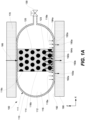
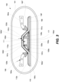
- FIGS. 1A -1D illustrate examples of pressurizable tooling device 100 for applying different pressure / force levels to different portions of surface 192 of object 190, which are also shown in these figures for reference.
- object 190 is not a part of pressurizable tooling device 100.
- Pressurizable tooling device 100 is used for processing object 190 and is a separate component. During processing, pressurizable tooling device 100 comes in contact with object 190 as, for example shown in FIGS. 1A-1D while applying different pressure / force levels to different portions of surface 192 of object 190.
- Pressurizable tooling device 100 comprises flexible wall 110 and contact member 120. Each of these components will now be described in more detail.
- Flexible wall 110 comprises first surface 114 and second surface 116, opposite of first surface 114.
- first surface 114 may be also referred to as outer surface
- second surface 116 may be referred to as an inner surface.
- first surface 114 comes in contact with surface 192 of object 190.
- Second surface 116 comprises two portions, contact portion 116b and non-contact portion 116a.
- contact member 120 may contact (e.g., during operation or at all times) or be attached to contact portion 116b of second surface 116 of flexible wall 110. Contact member 120 does not contact non-contact portion 116a of second surface 116.
- This position of contact member 120 relative to contact portion 116b and non-contact portion 116a of second surface 116 allows subjecting contact portion 116b and non-contact portion 116a to different pressure / force levels during operation. Specifically, controlling the level of contact between contact member 120 and contact portion 116b (e.g., by controlling the force applied to contact member 120) allows to control the total pressure / force applied to contact portion 116b. It should be noted that this total pressure / force is a combination of a pressure exerted uniformly to entire second surface 116 (which may be referred to as first pressure 194a) and a pressure exerted exclusively to contact portion 116b by contact member 120 (which may be referred to second pressure 194b).
- First pressure 194a may be a hydraulic pressure or a pneumatic pressure and is exerted by a fluid (e.g., liquid or gas) contacting entire second surface 116.
- second pressure 194b may be a mechanical pressure exerted by contact member 120 and determined by the level of contact between contact member 120 and contact portion 116b.
- the total pressure (i.e., a combination of first pressure 194a and second pressure 194b) exerted to contact portion 116b may be higher than the pressure (i.e., first pressure 194a) exerted on non-contact portion 116a.
- second pressure 194b applied by contact member 120 onto contact portion 116b may be referred to as a positive pressure.
- first pressure 194a and second pressure 194b and corresponding forces are applied in the same direction as, for example, shown in FIG. 1A . It should be noted that forces associated with first pressure 194a may not always have the same direction as forces associated with second pressure 194b (or simply second forces).
- first pressure 194a the forces associated with first pressure 194a are directed toward surface 192 of object 190.
- contact member 120 may either push flexible wall 110 toward surface 192 or pull flexible wall 110 away from surface 192.
- contact member 120 may be attached to flexible wall 110 or, more specifically, to contact portion 116b of flexible wall.
- contact member 120 may pull contact portion 116b away from object 190, in which case the total pressure (i.e., a combination of first pressure 194a and second pressure 194b and corresponding forces) exerted to contact portion 116b may be less than first pressure 194a (exerted on non-contact portion 116a).
- the pressure / force applied by contact member 120 onto contact portion 116b may be referred to as a negative pressure / negative force.
- Contact member 120 may be permeable to one or more fluids used for applying first pressure 194a. This permeability feature allows the fluids to exert first pressure 194a directly to contact portion 116b of flexible wall 110 rather than transferring this pressure through contact member 120.
- contact member 120 may have open cells or other types of openings 123 that allow the fluid to reach contact portion 116b of second surface 116 even when contact member 120 is in contact with this contact portion 116b.
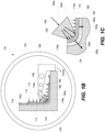
- Some examples of contact member 120 include open-cell foam 122 (illustrated in FIG. 5A ), spring 124 (illustrated in FIG. 5B ), and the like.
- pressurizing fluid While the pressurizing fluid is supplied and/or removed (e.g., from bladder 111), this fluid flows through contact member 120.
- the pressurizing fluid may be removed from pressurizable tooling device 100 or, more specifically, from bladder 111 (shown in FIG. 1A ) or from pressure chamber 101 (shown in FIG. 1B ) prior to using pressurizable tooling device 100.
- the contact member 120 may be non-permeable. In this case, contact member 120 blocks the pressurizing fluid from reaching a portion of flexible wall 110 where contact member 120 interfaced with flexible wall 110. In some arrangements, the force, with which contact member 120 acts on flexible wall 110, only corresponds to second force 193b applied to object 190 and there is no contribution from the pressurized fluid in this second portion 192b of the object surface.
- contact member 120 may be operable as a piston and may generate an additional force from pressurized fluid (e.g., when contact member 120 does not extend across the bladder formed by the flexible wall).
- contact member 120 may not apply any additional pressure and/or force on flexible wall 110 or, more specifically, on contact portion 116b of flexible wall 110.
- both contact portion 116b and non-contact portion 116a may be subjected to the same pressure (e.g., from the pressurizing fluid contacting second surface 116).
- contact member 120 may be separated from contact portion 116b (i.e., not contact this portion) during some operating stages. This ability to separate may be used, for example, for removal / replacement of contact member 120 when not in use, application of the uniform pressure (e.g., when contact member 120 does not contact flexible wall110 and second pressure 194b is effectively zero), and other purposes.
- contact member 120 is attached to contact portion 116b of second surface 116.
- contact member 120 may be glued to, adhered to, molded into, welded to, monolithically integrated to contact portion 116b, or otherwise coupled together.
- Contact member 120 may be permanently attached to contact portion 116b of second surface 116 or removably attached.
- contact member 120 may be unattached to contact portion 116b of second surface 116, which allows to move contact member 120 away from contact portion 116b.
- Contact member 120 may be compressible, in addition or instead of being permeable. This compressible feature may be used to conform contact member 120 to various shapes of contact portion 116b and/or to control the pressure / force distribution which contact member 120 exerts onto contact portion 116b.
- the level of compression of contact member 120 may correspond to the force and pressure exerted onto contact portion 116b (e.g., higher dimensional compression corresponding to a higher pressure and vice versa).
- the compressible feature may be used to ensure that contact member 120 conforms to contact portion 116b.
- first surface 114 of flexible wall 110 may conform to surfaces 192 of object 190, which may change the shape of contact portion 116b.
- the compressibility of contact member 120 may allow for these changes in shape without loss of contact between contact member 120 and contact portion 116b.
- Some examples of contact member 120 are an open-cell foam 122 (shown in FIG. 5A ), spring 124 (shown in FIG. 5B ), and a hydraulic device.
- contact member 120 may be a non-compressible (e.g., a metal block).
- the non-compressible feature may be useful when surface 192 of object 190 may need to be smoothened (e.g., planarized) while being processed with inflatable tooling device 100.
- surface 121 of contact member 120 (which contacts flexible wall 110 or, more specifically, contact portion 116b of second surface 116) may be non-planar as, for example, show in FIG. 5C .
- Non-planar surface 121 may be used, for example, to exert uneven pressure (provide uneven force distribution) onto contact portion 116b surface 116 and/or to apply even pressure (provide even force distribution) when the profile of surface 121 matches the profile of second portion 192b of surface 192 of object 190 (assuming that flexible 110 can easily conform to any profile).
- the difference between even or uneven pressure / force distribution exerted by surface 121 of contact member 120 (onto contact portion 116b of second surface 116) may depend, for example, on the compression of contact member 120.
- the shapes of surface 121 and second portion 192b are different (e.g., one is planar and the one is non-planar), then contact member 120 will be compressed differently at different points on surface 121. The points with a higher compression will experience higher pressures / forces and vice versa.
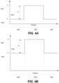
- FIG. 4D illustrates one example of an uneven pressure profile applied to second surface 116. This pressure profile example may be a result of applying pressure / force onto a planar surface of object 190 with contact member 120 shown in FIG. 5C . Referring again to FIG.
- the second pressure is greater at the center (P 2-max ) than at the edges (P 2-min ) because the compression of contact member 120 at the center is greater (the center of contact member 120 protrudes further than the edges resulting in a higher pressure).
- the center of contact portion 116b will experience a higher pressure total pressure (P t-max ) that the edges (P t-min ). If the shape of surface 121 of contact member 120 and second portion 192b are both planar or both non-planar but complementary, then the pressure exerted by contact member 120 may be uniform throughout second portion 192b as, for example, shown in FIGS. 4A-4C .
- the pressure corresponding to second portion 192b (P t ) is typically different from the pressure corresponding to first portion 192a (P 1 ). Furthermore, the pressure corresponding to first portion 192a (P 1 ) is generally uniform. As noted earlier, any possible pressure variations in first portion 192a (e.g., due to stretching of flexible wall 110) are negligible relative to a typical difference between the pressure corresponding to second portion 192b (P t ) and the pressure corresponding to first portion 192a (P 1 ).
- flexible wall 110 is formed from an elastomeric material e.g., rubber, polymer.
- flexible wall 110 may be stretchable.
- flexible wall 110 may be non-stretchable.
- flexible wall 110 may be formed from a thin flexible sheet of metal (e.g., foil).
- Flexible wall 110 may easily conform to the shape second portion 192b without exerting substantial additional pressure / forces onto second portion 192b and/or contact member 120 (e.g., due to deformation and/or stretching). Thereby pressure / forces applied to flexible wall 110 by the pressurizing fluid and contact member 120 may be the same as pressure / forces applied by flexible wall 110 onto surface 192 of object 190.
- the thickness of flexible wall 110 may be uniform.
- flexible wall 110 may form bladder 111 comprising internal cavity 112.
- bladder 111 may be also referred to as an inflatable mandrel.
- Contact member 120 may be disposed within internal cavity 112 of bladder 111.
- Flexible wall 110 may comprise valve 130 for filling internal cavity 112 of bladder 111 with pressurizing fluid e.g., liquid or gas.
- Valve 130 is connectable to source 182 of pressurizing fluid e.g., gas tank, pump and/or to a device for removing the fluid from bladder 111, e.g., pump.
- contact member 120 extends across bladder 111 and interfaces contact portion 116b of second surface 116 and additional contact portion 116c of second surface 116 as, for example, shown in FIG. 1A .
- Additional contact portion 116c may provide support to contact member 120 while contact member 120 exerts pressure/force on contact portion 116b.
- contact member 120 does not need to be externally supported, e.g., using positioning device 184 as later described with reference to FIG. 1B .
- the distance between contact portion 116b and additional contact portion 116c of flexible wall 110 (which may be referred to as a thickness of bladder 111) may be used to control the compression of contact member 120 and, as a result, the pressure / force, which contact member 120 exerts on contact portion 116b.
- bladder 111 may be compressed or expanded to control second pressure 194b and corresponding forces acting onto flexible wall 110. It should be noted that the amount of fluid inside bladder 111 controls first pressure 194a and corresponding forces acting onto flexible wall 110.
- pressurizable tooling device 100 further comprises positioning device 184 supporting contact member 120.
- Positioning device 184 may be configured to move contact member 120 relative to flexible wall 110 and, in some arrangements, to apply force to contact member 120. This movement may be used to control the pressure and/or force exerted by contact member 120 onto flexible wall or, more specifically, onto contact portion 116b of flexible wall 110. This exerted pressure / force is then transferred by flexible wall 110 to surface 192 of object 190.
- positioning device 184 may force contact member 120 toward object 190 to increase the pressure / force.
- positioning device 184 may move contact member 120 away from object 190 to decrease the pressure / force.
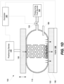
- pressurizable tooling device 100 may comprise pressure chamber 101. Flexible wall 110 and contact member 120 are disposed within pressure chamber 101. During operation of pressurizable tooling device 100, object 190 is also disposed inside pressure chamber 101. Pressure chamber 101 may be used to contain the pressurizing fluid while applying first pressure 194a and corresponding forces to flexible wall 110. Similar to the example presented in FIG. 1A , flexible wall 110 is positioned between the pressurizing fluid and object 190 in the example shown in FIG. 1B . Pumping the pressurizing fluid in or out of pressure chamber 101 changes first pressure 194a resulting in different forces applied to non-contact portion 116a of flexible wall 110 and a corresponding portion of object 190. It should be noted that pressure chamber 101 may also operate at an ambient pressure such that first pressure 194a is not applied to flexible wall 110.
- Flexible wall 110 may comprise seal 115 for sealing flexible wall 110 against back support 170 (as shown in FIG. 1B ) or, in another example, against surface 192 of object 190.
- Seal 115 may extend the entire perimeter of flexible wall 110. Due to seal 115, the pressurizing fluid is not able to go between flexible wall 110 and object 190, thereby creating a pressure differential and application of first pressure 194a onto flexible wall 110 and against object 190. Furthermore, when the pressure inside pressure chamber 101 is changed, the pressure across flexible wall 110 is also changed thereby exerting pressure / force on surface 192 of object 190 contacting flexible wall 110.
- One example of pressure chamber 101 is an autoclave. However, other types of chambers are also within the scope.
- pressurizable tooling device 100 may comprise controller 180 and valve 130.
- Controller 180 may be communicatively coupled to valve 130 for controlling the flow of pressurizing fluid and thereby control first pressure 194a and corresponding force.
- pressurizable tooling device 100 further comprises positioning device 184 communicatively coupled to controller 180.
- controller 180 may be used to control operation of positioning device 184 and the force which positioning device 184 exerts on the flexible wall.
- positioning device 184 supports contact member 120 and is operable to move contact member 120.
- Positioning device 184 may be used to control the level of contact (e.g., pressure and/or force) between contact member 120 and contact portion 116b of second surface 116 of flexible wall 110, which in turns determines second pressure 194b.
- Object 190 may be supported using back support 170, against the force exerted by positioning device 184.
- the force with which positioning device 184 is pressed against flexible wall may be controlled to help with ply shearing/slipping relative to each other and reduce or eliminate wrinkling. Furthermore, this force control may be used to eliminate or reduce "bridging". In some arrangements, the relative position of back support 170 and positioning device 184 determine second pressure 194b.
- Positioning device 184 may directly support contact member 120 as, for example, shown in FIG. 1B .
- positioning device 184 may be an arm (e.g., a robotic arm) movable within pressure chamber 101.
- FIG. 1B A brief example of processing object 190 in pressurizable tooling device 100 shown in FIG. 1B may be useful to illustrate some feature of pressurizable tooling device 100.
- Object 190 may be originally formed on a planar substrate (e.g., a forming mandrel) or pre-shaped using other tools, before being shaped into the final form as shown in FIG. 1B .
- object 190 may be already shaped into the final form prior to utilizing inflatable tooling device 100, and pressurizable tooling device 100 may be used to retain this shape.
- Pressurizable tooling device 100 may be used in conjunction with other tools / devices.
- the shaping of object 190 may be performed using a combination of back support 170 and positioning device 184, e.g., forcing object 190 into the corner of back support 170 using force applied to positioning device 184 and transferred to flexible wall 110 and then to object 190. It should be noted that this force may need to be applied at a particular location, e.g., at the corner.
- forcing object 190 against back support 170 may involve pressurizing the interior of pressure chamber 101 thereby creating first pressure 194a in addition or instead of applying a force to positioning device 184.
- Back support 170 is effectively operable as a form for object 190 and object may change its shape until it conforms to back support 170.
- object 190 When object 190 is a multi-ply object (e.g., a composite object), during this shaping operation, the inner plies may slip relative to the outer plies to avoid wrinkling.
- Various combinations of forces and/or pressures may be used to avoid wrinkling and/or to ensure that object 190 has a desired shape and size / thickness (e.g., a desired fiber to volume ratio).
- second pressure 194b (and the corresponding force) may be applied before applying first pressure 194a (and the corresponding force) to allow the inner plies to slip and to avoid wrinkling.
- First pressure 194a (and the corresponding force) may be then controlled to achieve a desirable thickness of object 190.
- controller 180 is configured to independently control first pressure 194a and second pressure 194b and corresponding forces.
- first pressure 194a and the corresponding force may be controlled by controlling valve 130, while second pressure 194b and the corresponding force may be controlled by controlling positioning device 184.
- Operation of valve 130 may be independent of operation of positioning device 184.
- Pressurizable tooling device 100 may further comprising sensor 186 communicatively coupled to controller 180.
- sensor 186 include, but are not limited to, a pressure sensor, a temperature sensor, and a visual sensor.
- Controller 180 may be configured to control one or more of first pressure 194a and second pressure 194b based on the input received from sensor 186. Other processing parameters may be also controlled based on the sensor input.
- pressurizable tooling device 100 further comprises heater 188.
- Heater 188 may be communicatively coupled to controller 180 and configured to control temperature of object 190. Specifically, during operation, heater 188 may be thermally coupled to object 190.
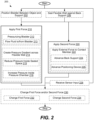
- FIG. 2 illustrates a process flowchart corresponding to method 200 of controlling application of forces 193a and 193b to first portion 192a and second portion 192b of surface 192 of object 190.
- method 200 may comprise positioning bladder 111 between object 190 and back support 170 (referring to block 202 in FIG. 2 ). This positioning operation may be performed while the pressure inside bladder 111 is less than the pressure outside of bladder 111.
- contact member 120 is compressible, and the positioning operation may be performed while contact member 120 is compressed.
- method 200 may comprise sealing flexible wall 111 against back support 170 (referring to block 206 in FIG. 2 ).
- object 190 is disposed in a sealed space between flexible wall 120 and back support 170.
- Method 200 comprises applying first force 193a to first portion 192a (referring to block 210 in FIG. 2 ).
- first force 193a may be applied using bladder 111 formed by flexible wall 110.
- applying first force 193a may comprise pressurizing bladder 111 (referring to block 212 in FIG. 2 ) or, more specifically, flowing the pressurizing fluid into bladder 111 (referring to block 213 in FIG. 3 ).
- first force 193a may comprise creating a pressure gradient across flexible wall 110 (referring to block 214 in FIG. 2 ).
- a pressure difference is created between the sealed space and the area outside of the sealed space, i.e., inside and outside of flexible wall 110.
- Operation 214 may comprise reducing the pressure in the sealed space (referring to block 215 in FIG. 2 ).
- operation 215 may be performed while maintaining the pressure outside of the sealed space (e.g., inside pressure chamber 101) at a constant level.
- the pressure outside of the sealed space may be an ambient pressure.
- operation 214 may involve increasing the pressure inside pressure chamber 101 (referring to block 218 in FIG. 2 ). In other words, the pressure in the area outside of the sealed space may be increased. Operation 218 may be performed while maintaining the pressure inside the sealed space at a constant level. In some arrangements, the constant level of the pressure inside the sealed space is at an ambient pressure level. Alternatively, operations 215 and operations 218 may be performed simultaneously.
- Method 200 further comprises applying second force 193b to second portion 192b (referring to block 220 in FIG. 2 ).
- applying second force 193b may comprise applying external force 195 to contact member 120.
- contact member 120 may be disposed inside bladder 111. If contact member 120 is permeable (as described above), then pressurizing bladder 111 during operation 212 further comprises applying first force 193a to second portion 192b in addition to applying second force 193b. Furthermore, if bladder 111 is positioned between object 190 and back support 170 (as, for example, shown in FIG. 1A ), then applying external force 195 to the contact member may comprise advancing back support 170 toward object 190.
- external force 195 may be applied to contact member 120 using positioning device 184.
- applying external force 195 to contact member 120 may comprise advancing positioning device 184 toward back support 170.
- the magnitude of first force 193a may be different from the magnitude of second force 193b as, for example, schematically shown in FIG. 4A .
- the vector of first force 193a and the vector of second force 193b have the same direction (i.e., both forces acting in the same direction).
- second portion 192b of the object surface experiences a combination of first force 193a and second force 193b (e.g., when contact member 120 is permeable), which may be referred to as total force 193c.
- first force 193a and the vector of second force 193b have opposite direction.
- second portion 192b of the object surface also experiences a combination of first force 193a and second force 193b (e.g., when contact member 120 is permeable), which may be referred to as total force 193c, but total force 193c is less than first force 193a.
- contact member 120 prior to applying second force 193b, contact member 120 is positioned away from flexible wall 110.
- contact member 120 may be attached to flexible wall 110. This attachment features allows to achieve vectors of first force 193a and second force 193b having opposite directions (e.g., contact member 120 may pull a portion of flexible wall 110 away from object 190).
- second portion 192b of surface 190 comprises a corner.
- the corner may need a higher force than, for example, a planar portion of the object surface. This additional force may be used to prevent bridging in the corner.
- applying first force 193a during operation 210 and applying second force 193b during operation 220 overlap in time. Furthermore, these two operations may be staggered time. For example, second force 193b may be applied before applying first force 193a.
- method 200 further comprises changing first force 193a or second force 193b (referring to block 230 in FIG. 2 ).
- Operation 230 may be performed while applying first force 193a and second force 193b.
- operations 210, 220, and 230 may be performed at the same time.
- operation 230 involves changing first force 193a (referring to block 232 in FIG. 2 ), while second force 193b may be kept the same. This example is illustrated by transition from FIG. 4A to FIG. 4B and may involve, for example, flowing the pressurized fluid into bladder 111.
- operation 230 involves changing second force 193b (referring to block 234 in FIG. 2 ), while first force 193a may be kept the same.
- method 200 comprises receiving sensor input (referring to block 228 in FIG. 2 ). In these arrangements, changing first force 193a and/or second force 193b during operation 230 may be performed based on this sensor input.
- the sensor input comprises one or more of a pressure input, a temperature input, and a visual input.
- Method 200 may be used for controlling application of forces to different portions of two surfaces 192' and 192" of object 190.
- Method 200 may comprise positioning bladder 111, formed by first flexible wall 110a, within cavity 171 formed object 190 and back support 170.
- Bladder 111 may comprise a cavity with first contact member 120a positioned inside the cavity.
- Method 200 may proceed with sealing second flexible wall 110b against object 190 or back support 170.
- Object 190 is disposed between second flexible wall 110b and back support 170.
- Method 200 also involves applying first force 193a to first portion 192a' of first surface 192' of object 190 using first flexible wall 110a.
- applying first force 193a may comprise pressurizing the bladder.
- Method 200 may proceed with applying second force 193b to second portion 192b' of first surface 192' of using first flexible wall 110a.
- Second portion 192b' corresponds to first contact member 120a.
- second portion 192b' may be corner 191c of object 190 thereby requiring a different force than, for example, first portion 192a'.
- Method 200 may also involve applying third force 193c onto third portion 192a" of second surface 192" using second flexible wall 110b.
- Third portion 192a" may correspond to second contact member 120b.
- Applying third force 193a may comprise applying external force 195 to second contact member 120b.
- method 200 may also comprise applying fourth force 193d to fourth portion 192b" of second surface 192" of object 190 using second flexible wall 110b.
- Applying fourth force 193d may comprise applying a pressure across second flexible wall 110b.
- pressure chamber 101 shown in FIG. 3 may be pressurized.
Description
- Pressurized bladders or diaphragms, which may be also referred to as inflatable mandrels or simply bags, are used in many applications to apply pressure to irregularly shaped surfaces or surfaces that may change shape during processing and application of the pressure. Specifically, a pressurizing fluid, such as a gas or liquid, may be flown into a bag thereby pressurizing the bag. The bag may be held against the surface of an object and exert a uniform pressure onto the surface, regardless the shape of the surface. The pressurizing fluid is only capable to uniformly exert the pressure on the interior surface of the bag. As such, typically, the bag is only capable of exerting uniform pressure onto the surface. While this pressure uniformity may be ideal for some applications, various other applications may benefit from something other than a uniform pressure distribution. For example, stretching/reshaping of various portions of the bag may cause bridging, i.e., when the bag separates or not adequately pressed on the part, and may require something more than pressure uniformity to overcome this stretching/reshaping. What is needed are methods and apparatuses for applying different pressure levels to different portions of surfaces.
-
US 2009/151576 , in accordance with its abstract, states: a hot press apparatus for hot pressing a thin plate-like workpiece, includes a base, lower and upper heating plates, a flat lower mold member, lower and upper frame members, a workpiece taking-out unit, an upper press plate, a heat-resistant and stretchable film member covering the lower end portion of the upper frame member, a heat medium filled in a heat medium-filling space above the film member, and a driving unit. A film member-horizontally holding member substantially horizontally holds the film member while preventing the film member from hanging, while keeping it at a substantially constant position as viewed in a horizontal direction. The workpiece is hot pressed with the film member by applying pressure to the heat medium inside the heat medium-filling space while the film member is prevented from expanding radially outwardly at an outer periphery thereof. -
DE 30 01 904 A in accordance with its abstract, states: one press plate for mounting a workpiece, and another with a membrane led over a sealing frame, together with a closing cylinder for these, and provision for subjecting the enclosed space with pressure medium, are incorporated in a membrane form press. There is a device for pre-forming the membrane in an initial form, making allowance for recessed surface sections of the workpiece. This is activated before the pressure compartment is subjected to full pressure. This enables such recessed surface sections to have the same decorative finish, esp. veneer as the rest. -
US 2016/339682 in accordance with its abstract, states: a structure comprising a plurality of walls defining a bladder cavity, the bladder cavity comprises an initial cross section size. A first plurality of wave features provided along at least one of the plurality of walls defining the bladder cavity. In one arrangement, the first plurality of wave features allow the structure to expand from the initial cross section size to a second cross section size after the structure becomes inflated during a composite charge cure, the second cross section size larger than the initial cross sectional size. -
US 2010/139850 in accordance with its abstract, states: a collapsible bladder has flexible outer walls and at least one strut inside the enclosure. The strut is connected to the outer walls and controls the shape into which the enclosure may be collapsed. -
US 6 199 613 B in accordance with its abstract, states: an apparatus for applying a pad to a component has a flexible diaphragm held in a continuous frame for holding the pad. On its front side which faces the component when the apparatus is in use, the frame has a circumferential, resilient gasket. Through a vacuum connection, a space between the diaphragm and the component is to be attached to a vacuum source. By that the pad applies itself against the component. - There is described herein a method of controlling application of forces to a first portion and a second portion of a surface of an object, the method comprising: applying a first force to the first portion of the surface of the object, the first force being applied by pressurizing a bladder formed by a flexible wall; and applying a second force to the second portion of the surface of the object, the second force being applied using the bladder; and wherein: applying the second force comprises applying an external force to a permeable contact member disposed inside the bladder; applying the first force and applying the second force overlaps in time, and a magnitude of the first force is different from a magnitude of the second force; and pressurizing the bladder further comprises applying the first force to the second portion of the surface of the object, in addition to the second force.
- There is also described herein a pressurizable tooling device comprising: a flexible wall, forming a bladder, the flexible wall comprising an inner surface, and the inner surface comprising a contact portion and a non-contact portion; a permeable contact member, contacting the contact portion of the inner surface of the flexible wall, the contact member being positioned away from the non-contact portion of the inner surface of the flexible wall; a valve; a controller; and a positioning device communicatively coupled to the controller wherein the positioning device supports contact member and is operable to move contact member; and wherein the controller is: communicatively coupled to the valve for controlling a pressure inside the bladder and thereby controlling first pressure and a corresponding first force; used to control operation of positioning device and the force which positioning device exerts on the flexible wall wherein the positioning device is used to control the level of contact between the contact member and contact portion of the inner surface of the flexible wall which in turn determines a second pressure and a corresponding second force; and configured to apply the first force and apply the second force overlapping in time, wherein a magnitude of the first force is different from a magnitude of the second force; and the contact member being permeable results in the first force being applied to the contact portion in addition to the second force.
-
-
FIGS. 1A - 1D are schematic illustrations of various examples of a pressurizable tooling device. -
FIG. 2 is a process flowchart corresponding to a method of processing an object, in accordance with some arrangements. -
FIG. 3 is an example of a pressurizable tooling device, in accordance with some arrangements. -
FIGS. 4A - 4D are different examples of a pressure profile on the surface of the processed object created using the pressurizable tooling device, in accordance with some arrangements. -
FIGS. 5A - 5C are schematic illustrations of different examples of a contact member of the pressurizable tooling device. - In the following description, numerous specific details are set forth in order to provide a thorough understanding of the presented concepts. The presented concepts may be practiced without some or all of these specific details. In other instances, well known process operations have not been described in detail so as to not unnecessarily obscure the described concepts. While some concepts will be described in conjunction with the specific examples, it will be understood that these examples are not intended to be limiting.
- Conventional pressurized bladders, which may be also referred to as inflatable mandrels, are typically used to apply pressure and forces to various surfaces of processed objects. In particular, pressurized bladders may be used to press on irregularly shaped surfaces and/or surfaces that change their shapes during processing. A design of such pressurized bladders combines a uniform interior pressure acting on the flexible wall of a bladder as well as the ability of this flexible wall to conform to different types of surfaces. However, these conventional devices are not designed to independently control levels of pressure and/or force applied to different portions of the same surface. The conventional pressurized bladders are generally limited to apply a uniform pressure / evenly distributed force to the entire surface.
- A pressurizable tooling device described herein addresses this deficiency and allows to independently control and change pressure levels and/or force levels applied to different portions of the same surface of an object. For example, processing of an object may require a higher pressure / force in one portion on the surface of this object (e.g., in a corner) and a lower pressure / force in another portion (e.g., on a planar portion). A single pressurizable tooling device may be used for this processing. Specifically, the same pressurizable tooling device may subject different portions of the same surface to different levels of pressure / force. These pressure / force levels may be substantially different and far exceed variations associated, for example, with stretching and/or corner effects. In some arrangements, the difference of the pressure / force magnitude (simultaneously applied to different portions of the same surface) may be at least about 25%, at least about 50%, at least about 100%, or even at least about 200%. It should be noted that, in some arrangements, the pressurizable tooling device (described herein) may be also used to apply substantially uniform pressure / force to the surface of the object (e.g., with pressure variations less than 10%, less than 5%, or even less than 1%), if such uniformity is needed. In other words, the described pressurizable tooling device retain the functionality of conventional pressurized bladders, while add additional features not previously available. For example, the independent pressure / force control at different portions of the surface may be also used to dynamically modify these levels during processing.
- This level of control may be particularly useful for curing composite objects (e.g., "green" composite structures) that have complex shapes. In this example, a higher pressure may be used at one or more location where a higher external pressure is expected. For example, a pressurizable tooling device may be used to support a "green" composite structure with an interior cavity of this structure against crushing when the composite structure is subjected to exterior consolidation forces (e.g., forces from a vacuum bag). One having ordinary skill in the art would understand that various other applications are also within the scope. In general, a pressurizable tooling device may be used for any applications requiring two or more different pressure levels. Furthermore, while general references are made to different pressure levels, one having ordinary skill in the art would understand, that applying a pressure corresponds to application of forces and a pressurizable tooling device can be used to apply difference forces. The term "force" and "pressure" may be used interchangeably in some instances.
- In some arrangements, the pressurizable tooling device includes a flexible wall and a contact member. During operation, a first side (e.g., an outer side) of the flexible wall may be positioned against the surface of the object. A first pressure is applied to a second side (e.g., an inner side) of the flexible wall (opposite of the first wall). For example, the flexible wall may form an enclosed bladder, which may be pressurized during this operation. The bladder may be position between the object and the back support. Alternatively, a stack including the flexible wall and the object may be positioned in a pressure chamber, which is pressurized to press the flexible wall against the object.
- The first pressure translates into a pressure and corresponding forces applied by the flexible wall to the surface of the object (which is being processed with the device). As such, a portion of the surface contacting the flexible wall experiences a first force. In some arrangements, the pressure/force applied to the object surface by the flexible wall may be substantially the same as the pressure/force applied to the second side (e.g., an inner side) of the flexible wall. In other words, the losses/deviations attributed to stretching/reshaping of the flexible wall may be negligible during this operation. However, in some instances, this stretching/reshaping may cause bridging (when the flexible wall does not follow the shape of the part. The force differentiation may be used to overcome bridging. For example, some portions of the flexible wall may be stretched more using additional force exerted by the contact member. Furthermore, the pneumatic pressure or the hydraulic pressure acting on the flexible wall is uniform. As such, the pressure and the force distribution transferred by the flexible wall to the surface of the object may be also uniform.
- The contact member contacts a portion of the second side of the flexible wall and applies a force to this portion, which may be also viewed as a second pressure, to distinguish it from the first pressure. Specifically, the contact member may be forced against the flexible wall using a controlled force (e.g., directly applied to the contact member using a positioning device, or by pressing onto the contact member through the flexible wall, when the contact member is positioned inside the bladder formed by the flexible wall). The amount of forced applied to the contact member may be selected based on the desired force and/or pressure that needs to be applied to the second portion of the object surface.
- In some arrangements, the contact member is permeable to the fluid. As such, the first pressure (e.g., produced by pressurizing the bladder) is also applied to the portion of the flexible wall interfacing the contact member. As such, the portion of the flexible wall, which contacts the contact member, may experience a combination of pressures and corresponding forces.
- It should be noted that different pressures / forces applied to different portions (e.g., the contact portion and the non-contact portion) of the inner surface of the flexible wall are transferred by the flexible wall to the object surface. As such, the object surface also experiences different levels of pressure and force. Assuming no losses through the flexible wall, these pressures / forces applied to the portions of the flexible wall would be the same as pressure / force levels acting on the surface of the object, which is in contact with the flexible wall. As such, the reference can be made to a first pressure / force being applied to the non-contact portion of the flexible wall and to a first portion of the surface of the object, which corresponds to this non-contact portion. Likewise, the reference can be made to a combined pressure / force (e.g., first and second pressure / force) being applied to the contact portion of the flexible wall and to a second portion of the surface of the object, which corresponds to this contact portion.
- As noted above, the pressurizable tooling device may also independently control each of the first pressure and the second pressure (and corresponding forces). This control may be performed without having to add or remove the pressurizable tooling device during processing or, more specifically, while applying pressure / forces using the device. For example, the first pressure may be kept the same (e.g., the fluid pressure inside the bladder formed by the flexible wall may be contestant), while the second pressure may be changed (e.g., by changing the level of contact between the contact member and the flexible wall or, more specifically, by changing the force with which the contact member is forced against the flexible wall). Alternatively, the first pressure may be changed (e.g., the fluid pressure inside the bladder formed by the flexible wall may be changed by pumping the fluid in or out of the bag), while the second pressure may be the same (e.g., by maintaining the same level of contact between the contact member and the flexible wall or, more specifically, not changing the force applied to the contact member). Furthermore, both the first pressure and the second pressure may be independently changed with respect to each other. This dynamic pressure / force approach is contrary to the conventional pressure bags, which are designed to exert uniform pressure on processed surfaces (with the pressure being uniform at all times, even if it is changed). As such, the pressurizable tooling device described herein allows higher levels of pressure control (e.g., independent control for different portions) thereby improving quality, saving the costs, reducing rework or repair, and allowing new types of processes and designs. The pressurizable tooling device also expands processing capabilities which could enable the performance of new work, or simplification of processes which may currently require multi-step processing.
-
FIGS. 1A -1D illustrate examples ofpressurizable tooling device 100 for applying different pressure / force levels to different portions ofsurface 192 ofobject 190, which are also shown in these figures for reference. One having ordinary skill in the art would understand thatobject 190 is not a part ofpressurizable tooling device 100.Pressurizable tooling device 100 is used forprocessing object 190 and is a separate component. During processing,pressurizable tooling device 100 comes in contact withobject 190 as, for example shown inFIGS. 1A-1D while applying different pressure / force levels to different portions ofsurface 192 ofobject 190. -
Pressurizable tooling device 100 comprisesflexible wall 110 andcontact member 120. Each of these components will now be described in more detail.Flexible wall 110 comprisesfirst surface 114 andsecond surface 116, opposite offirst surface 114. Whenflexible wall 110 forms a bladder as, for example, is shown inFIG. 1A ,first surface 114 may be also referred to as outer surface, whilesecond surface 116 may be referred to as an inner surface. - During operation of
pressurizable tooling device 100,first surface 114 comes in contact withsurface 192 ofobject 190.Second surface 116 comprises two portions,contact portion 116b andnon-contact portion 116a. Referring toFIGS. 1A and1C ,contact member 120 may contact (e.g., during operation or at all times) or be attached to contactportion 116b ofsecond surface 116 offlexible wall 110.Contact member 120 does not contactnon-contact portion 116a ofsecond surface 116. - This position of
contact member 120 relative to contactportion 116b andnon-contact portion 116a ofsecond surface 116 allows subjectingcontact portion 116b andnon-contact portion 116a to different pressure / force levels during operation. Specifically, controlling the level of contact betweencontact member 120 andcontact portion 116b (e.g., by controlling the force applied to contact member 120) allows to control the total pressure / force applied to contactportion 116b. It should be noted that this total pressure / force is a combination of a pressure exerted uniformly to entire second surface 116 (which may be referred to asfirst pressure 194a) and a pressure exerted exclusively to contactportion 116b by contact member 120 (which may be referred tosecond pressure 194b).First pressure 194a may be a hydraulic pressure or a pneumatic pressure and is exerted by a fluid (e.g., liquid or gas) contacting entiresecond surface 116. As shown inFIG. 1A ,second pressure 194b may be a mechanical pressure exerted bycontact member 120 and determined by the level of contact betweencontact member 120 andcontact portion 116b. - For example, the total pressure (i.e., a combination of
first pressure 194a andsecond pressure 194b) exerted to contactportion 116b may be higher than the pressure (i.e.,first pressure 194a) exerted onnon-contact portion 116a. In this example,second pressure 194b applied bycontact member 120 ontocontact portion 116b may be referred to as a positive pressure. In other words,first pressure 194a andsecond pressure 194b and corresponding forces are applied in the same direction as, for example, shown inFIG. 1A .
It should be noted that forces associated withfirst pressure 194a may not always have the same direction as forces associated withsecond pressure 194b (or simply second forces). In general, the forces associated withfirst pressure 194a are directed towardsurface 192 ofobject 190. However,contact member 120 may either pushflexible wall 110 towardsurface 192 or pullflexible wall 110 away fromsurface 192. For example,contact member 120 may be attached toflexible wall 110 or, more specifically, to contactportion 116b of flexible wall. In this example,contact member 120 may pullcontact portion 116b away fromobject 190, in which case the total pressure (i.e., a combination offirst pressure 194a andsecond pressure 194b and corresponding forces) exerted to contactportion 116b may be less thanfirst pressure 194a (exerted onnon-contact portion 116a). In this example, the pressure / force applied bycontact member 120 ontocontact portion 116b may be referred to as a negative pressure / negative force.
Contact member 120 may be permeable to one or more fluids used for applyingfirst pressure 194a. This permeability feature allows the fluids to exertfirst pressure 194a directly to contactportion 116b offlexible wall 110 rather than transferring this pressure throughcontact member 120. For example,contact member 120 may have open cells or other types ofopenings 123 that allow the fluid to reachcontact portion 116b ofsecond surface 116 even whencontact member 120 is in contact with thiscontact portion 116b. Some examples ofcontact member 120 include open-cell foam 122 (illustrated inFIG. 5A ), spring 124 (illustrated inFIG. 5B ), and the like. While the pressurizing fluid is supplied and/or removed (e.g., from bladder 111), this fluid flows throughcontact member 120. In some arrangements, the pressurizing fluid may be removed frompressurizable tooling device 100 or, more specifically, from bladder 111 (shown inFIG. 1A ) or from pressure chamber 101 (shown inFIG. 1B ) prior to usingpressurizable tooling device 100. - In an arrangement outside the scope of the claims, the
contact member 120 may be non-permeable. In this case,contact member 120 blocks the pressurizing fluid from reaching a portion offlexible wall 110 wherecontact member 120 interfaced withflexible wall 110. In some arrangements, the force, with whichcontact member 120 acts onflexible wall 110, only corresponds tosecond force 193b applied to object 190 and there is no contribution from the pressurized fluid in thissecond portion 192b of the object surface. Alternatively,contact member 120 may be operable as a piston and may generate an additional force from pressurized fluid (e.g., whencontact member 120 does not extend across the bladder formed by the flexible wall).
In some states,contact member 120 may not apply any additional pressure and/or force onflexible wall 110 or, more specifically, oncontact portion 116b offlexible wall 110. In these states, bothcontact portion 116b andnon-contact portion 116a may be subjected to the same pressure (e.g., from the pressurizing fluid contacting second surface 116). Furthermore,contact member 120 may be separated fromcontact portion 116b (i.e., not contact this portion) during some operating stages. This ability to separate may be used, for example, for removal / replacement ofcontact member 120 when not in use, application of the uniform pressure (e.g., whencontact member 120 does not contact flexible wall110 andsecond pressure 194b is effectively zero), and other purposes.
In some arrangements,contact member 120 is attached to contactportion 116b ofsecond surface 116. For example,contact member 120 may be glued to, adhered to, molded into, welded to, monolithically integrated to contactportion 116b, or otherwise coupled together.Contact member 120 may be permanently attached to contactportion 116b ofsecond surface 116 or removably attached. Alternatively,contact member 120 may be unattached to contactportion 116b ofsecond surface 116, which allows to movecontact member 120 away fromcontact portion 116b.
Contact member 120 may be compressible, in addition or instead of being permeable. This compressible feature may be used to conformcontact member 120 to various shapes ofcontact portion 116b and/or to control the pressure / force distribution whichcontact member 120 exerts ontocontact portion 116b. For example, the level of compression of contact member 120 (e.g., dimensional changes ofcontact member 120 along the Z axis) may correspond to the force and pressure exerted ontocontact portion 116b (e.g., higher dimensional compression corresponding to a higher pressure and vice versa). Furthermore, the compressible feature may be used to ensure thatcontact member 120 conforms to contactportion 116b. Specifically,first surface 114 offlexible wall 110 may conform tosurfaces 192 ofobject 190, which may change the shape ofcontact portion 116b. The compressibility ofcontact member 120 may allow for these changes in shape without loss of contact betweencontact member 120 andcontact portion 116b. Some examples ofcontact member 120 are an open-cell foam 122 (shown inFIG. 5A ), spring 124 (shown inFIG. 5B ), and a hydraulic device. - Alternatively,
contact member 120 may be a non-compressible (e.g., a metal block). The non-compressible feature may be useful whensurface 192 ofobject 190 may need to be smoothened (e.g., planarized) while being processed withinflatable tooling device 100. - In some arrangements,
surface 121 of contact member 120 (which contactsflexible wall 110 or, more specifically,contact portion 116b of second surface 116) may be non-planar as, for example, show inFIG. 5C .Non-planar surface 121 may be used, for example, to exert uneven pressure (provide uneven force distribution) ontocontact 116 and/or to apply even pressure (provide even force distribution) when the profile ofportion 116b surfacesurface 121 matches the profile ofsecond portion 192b ofsurface 192 of object 190 (assuming that flexible 110 can easily conform to any profile). - The difference between even or uneven pressure / force distribution exerted by
surface 121 of contact member 120 (ontocontact portion 116b of second surface 116) may depend, for example, on the compression ofcontact member 120. For example, if the shapes ofsurface 121 andsecond portion 192b are different (e.g., one is planar and the one is non-planar), then contactmember 120 will be compressed differently at different points onsurface 121. The points with a higher compression will experience higher pressures / forces and vice versa. For example,FIG. 4D illustrates one example of an uneven pressure profile applied tosecond surface 116. This pressure profile example may be a result of applying pressure / force onto a planar surface ofobject 190 withcontact member 120 shown inFIG. 5C . Referring again toFIG. 4D , the second pressure is greater at the center (P2-max) than at the edges (P2-min) because the compression ofcontact member 120 at the center is greater (the center ofcontact member 120 protrudes further than the edges resulting in a higher pressure). As a result, the center ofcontact portion 116b will experience a higher pressure total pressure (Pt-max) that the edges (Pt-min). If the shape ofsurface 121 ofcontact member 120 andsecond portion 192b are both planar or both non-planar but complementary, then the pressure exerted bycontact member 120 may be uniform throughoutsecond portion 192b as, for example, shown inFIGS. 4A-4C . It should be note that the pressure corresponding tosecond portion 192b (Pt) is typically different from the pressure corresponding tofirst portion 192a (P1). Furthermore, the pressure corresponding tofirst portion 192a (P1) is generally uniform. As noted earlier, any possible pressure variations infirst portion 192a (e.g., due to stretching of flexible wall 110) are negligible relative to a typical difference between the pressure corresponding tosecond portion 192b (Pt) and the pressure corresponding tofirst portion 192a (P1). - Turning to another component of
pressurizable tooling device 100, in some arrangements,flexible wall 110 is formed from an elastomeric material e.g., rubber, polymer. As such,flexible wall 110 may be stretchable. Alternatively,flexible wall 110 may be non-stretchable. For example,flexible wall 110 may be formed from a thin flexible sheet of metal (e.g., foil).Flexible wall 110 may easily conform to the shapesecond portion 192b without exerting substantial additional pressure / forces ontosecond portion 192b and/or contact member 120 (e.g., due to deformation and/or stretching). Thereby pressure / forces applied toflexible wall 110 by the pressurizing fluid andcontact member 120 may be the same as pressure / forces applied byflexible wall 110 ontosurface 192 ofobject 190. The thickness offlexible wall 110 may be uniform. - Referring to
FIG. 1A ,flexible wall 110 may formbladder 111 comprisinginternal cavity 112. In this example,bladder 111 may be also referred to as an inflatable mandrel.Contact member 120 may be disposed withininternal cavity 112 ofbladder 111.Flexible wall 110 may comprisevalve 130 for fillinginternal cavity 112 ofbladder 111 with pressurizing fluid e.g., liquid or gas.Valve 130 is connectable to source 182 of pressurizing fluid e.g., gas tank, pump and/or to a device for removing the fluid frombladder 111, e.g., pump. - In some arrangements,
contact member 120 extends acrossbladder 111 andinterfaces contact portion 116b ofsecond surface 116 andadditional contact portion 116c ofsecond surface 116 as, for example, shown inFIG. 1A .Additional contact portion 116c may provide support to contactmember 120 whilecontact member 120 exerts pressure/force oncontact portion 116b. In this approach,contact member 120 does not need to be externally supported, e.g., usingpositioning device 184 as later described with reference toFIG. 1B . The distance betweencontact portion 116b andadditional contact portion 116c of flexible wall 110 (which may be referred to as a thickness of bladder 111) may be used to control the compression ofcontact member 120 and, as a result, the pressure / force, whichcontact member 120 exerts oncontact portion 116b. As such,bladder 111 may be compressed or expanded to controlsecond pressure 194b and corresponding forces acting ontoflexible wall 110. It should be noted that the amount of fluid insidebladder 111 controlsfirst pressure 194a and corresponding forces acting ontoflexible wall 110. - Referring to
FIG. 1B , in some arrangements,pressurizable tooling device 100 further comprisespositioning device 184 supportingcontact member 120.Positioning device 184 may be configured to movecontact member 120 relative toflexible wall 110 and, in some arrangements, to apply force to contactmember 120. This movement may be used to control the pressure and/or force exerted bycontact member 120 onto flexible wall or, more specifically, ontocontact portion 116b offlexible wall 110. This exerted pressure / force is then transferred byflexible wall 110 to surface 192 ofobject 190. For example,positioning device 184 may forcecontact member 120 towardobject 190 to increase the pressure / force. Alternatively,positioning device 184 may movecontact member 120 away fromobject 190 to decrease the pressure / force. - Referring to
FIG. 1B ,pressurizable tooling device 100 may comprisepressure chamber 101.Flexible wall 110 andcontact member 120 are disposed withinpressure chamber 101. During operation ofpressurizable tooling device 100,object 190 is also disposed insidepressure chamber 101.Pressure chamber 101 may be used to contain the pressurizing fluid while applyingfirst pressure 194a and corresponding forces toflexible wall 110. Similar to the example presented inFIG. 1A ,flexible wall 110 is positioned between the pressurizing fluid andobject 190 in the example shown inFIG. 1B . Pumping the pressurizing fluid in or out ofpressure chamber 101 changesfirst pressure 194a resulting in different forces applied tonon-contact portion 116a offlexible wall 110 and a corresponding portion ofobject 190. It should be noted thatpressure chamber 101 may also operate at an ambient pressure such thatfirst pressure 194a is not applied toflexible wall 110. -
Flexible wall 110 may compriseseal 115 for sealingflexible wall 110 against back support 170 (as shown inFIG. 1B ) or, in another example, againstsurface 192 ofobject 190. As such, a combination offlexible wall 110,back support 170, andpressure chamber 101 are collectively operable as an inflatable mandrel.Seal 115 may extend the entire perimeter offlexible wall 110. Due to seal 115, the pressurizing fluid is not able to go betweenflexible wall 110 andobject 190, thereby creating a pressure differential and application offirst pressure 194a ontoflexible wall 110 and againstobject 190. Furthermore, when the pressure insidepressure chamber 101 is changed, the pressure acrossflexible wall 110 is also changed thereby exerting pressure / force onsurface 192 ofobject 190 contactingflexible wall 110. One example ofpressure chamber 101 is an autoclave. However, other types of chambers are also within the scope. - Referring to
FIG. 1D ,pressurizable tooling device 100 may comprisecontroller 180 andvalve 130.Controller 180 may be communicatively coupled tovalve 130 for controlling the flow of pressurizing fluid and thereby controlfirst pressure 194a and corresponding force. - In some arrangements,
pressurizable tooling device 100 further comprisespositioning device 184 communicatively coupled tocontroller 180. As such,controller 180 may be used to control operation ofpositioning device 184 and the force whichpositioning device 184 exerts on the flexible wall. Some aspects ofpositioning device 184 are described above. For example,positioning device 184 supportscontact member 120 and is operable to movecontact member 120.Positioning device 184 may be used to control the level of contact (e.g., pressure and/or force) betweencontact member 120 andcontact portion 116b ofsecond surface 116 offlexible wall 110, which in turns determinessecond pressure 194b.Object 190 may be supported using backsupport 170, against the force exerted by positioningdevice 184. The force with whichpositioning device 184 is pressed against flexible wall may be controlled to help with ply shearing/slipping relative to each other and reduce or eliminate wrinkling. Furthermore, this force control may be used to eliminate or reduce "bridging". In some arrangements, the relative position ofback support 170 andpositioning device 184 determinesecond pressure 194b. -
Positioning device 184 may directly supportcontact member 120 as, for example, shown inFIG. 1B . Specifically,positioning device 184 may be an arm (e.g., a robotic arm) movable withinpressure chamber 101. - A brief example of
processing object 190 inpressurizable tooling device 100 shown inFIG. 1B may be useful to illustrate some feature ofpressurizable tooling device 100.Object 190 may be originally formed on a planar substrate (e.g., a forming mandrel) or pre-shaped using other tools, before being shaped into the final form as shown inFIG. 1B . Furthermore, object 190 may be already shaped into the final form prior to utilizinginflatable tooling device 100, andpressurizable tooling device 100 may be used to retain this shape.Pressurizable tooling device 100 may be used in conjunction with other tools / devices. - In some arrangements, the shaping of
object 190 may be performed using a combination ofback support 170 andpositioning device 184, e.g., forcingobject 190 into the corner ofback support 170 using force applied topositioning device 184 and transferred toflexible wall 110 and then to object 190. It should be noted that this force may need to be applied at a particular location, e.g., at the corner. In some arrangements, forcingobject 190 againstback support 170 may involve pressurizing the interior ofpressure chamber 101 thereby creatingfirst pressure 194a in addition or instead of applying a force topositioning device 184.Back support 170 is effectively operable as a form forobject 190 and object may change its shape until it conforms to backsupport 170. Whenobject 190 is a multi-ply object (e.g., a composite object), during this shaping operation, the inner plies may slip relative to the outer plies to avoid wrinkling. Various combinations of forces and/or pressures (as further described below with reference to FIGA. 2A and 2B) may be used to avoid wrinkling and/or to ensure thatobject 190 has a desired shape and size / thickness (e.g., a desired fiber to volume ratio). For example,second pressure 194b (and the corresponding force) may be applied before applyingfirst pressure 194a (and the corresponding force) to allow the inner plies to slip and to avoid wrinkling.First pressure 194a (and the corresponding force) may be then controlled to achieve a desirable thickness ofobject 190. - Referring to
FIG. 1D , in some arrangements,controller 180 is configured to independently controlfirst pressure 194a andsecond pressure 194b and corresponding forces. For example,first pressure 194a and the corresponding force may be controlled by controllingvalve 130, whilesecond pressure 194b and the corresponding force may be controlled by controllingpositioning device 184. Operation ofvalve 130 may be independent of operation ofpositioning device 184. -
Pressurizable tooling device 100 may further comprisingsensor 186 communicatively coupled tocontroller 180. Some examples ofsensor 186 include, but are not limited to, a pressure sensor, a temperature sensor, and a visual sensor.Controller 180 may be configured to control one or more offirst pressure 194a andsecond pressure 194b based on the input received fromsensor 186. Other processing parameters may be also controlled based on the sensor input. - In some arrangements,
pressurizable tooling device 100 further comprisesheater 188.Heater 188 may be communicatively coupled tocontroller 180 and configured to control temperature ofobject 190. Specifically, during operation,heater 188 may be thermally coupled to object 190. -
FIG. 2 illustrates a process flowchart corresponding tomethod 200 of controlling application offorces first portion 192a andsecond portion 192b ofsurface 192 ofobject 190. - In some arrangements, operations of
method 200 are performed using an example ofpressurizable tooling device 100 shown inFIG. 1A . In these arrangements,method 200 may comprise positioningbladder 111 betweenobject 190 and back support 170 (referring to block 202 inFIG. 2 ). This positioning operation may be performed while the pressure insidebladder 111 is less than the pressure outside ofbladder 111. For example,contact member 120 is compressible, and the positioning operation may be performed whilecontact member 120 is compressed. - Alternatively, operations of
method 200 are performed using an example ofpressurizable tooling device 100 shown inFIGS. 1B and 1C . In these arrangements,method 200 may comprise sealingflexible wall 111 against back support 170 (referring to block 206 inFIG. 2 ). As shown inFIGS. 1B and 1C ,object 190 is disposed in a sealed space betweenflexible wall 120 andback support 170. -
Method 200 comprises applyingfirst force 193a tofirst portion 192a (referring to block 210 inFIG. 2 ). Referring to the example shown inFIG. 1A ,first force 193a may be applied usingbladder 111 formed byflexible wall 110. Specifically, applyingfirst force 193a may comprise pressurizing bladder 111 (referring to block 212 inFIG. 2 ) or, more specifically, flowing the pressurizing fluid into bladder 111 (referring to block 213 inFIG. 3 ). - Referring to the example shown in
FIG. 1B ,first force 193a may comprise creating a pressure gradient across flexible wall 110 (referring to block 214 inFIG. 2 ). In other words, a pressure difference is created between the sealed space and the area outside of the sealed space, i.e., inside and outside offlexible wall 110.Operation 214 may comprise reducing the pressure in the sealed space (referring to block 215 inFIG. 2 ). For example,operation 215 may be performed while maintaining the pressure outside of the sealed space (e.g., inside pressure chamber 101) at a constant level. For example, the pressure outside of the sealed space may be an ambient pressure. - In some arrangements,
operation 214 may involve increasing the pressure inside pressure chamber 101 (referring to block 218 inFIG. 2 ). In other words, the pressure in the area outside of the sealed space may be increased.Operation 218 may be performed while maintaining the pressure inside the sealed space at a constant level. In some arrangements, the constant level of the pressure inside the sealed space is at an ambient pressure level. Alternatively,operations 215 andoperations 218 may be performed simultaneously. -
Method 200 further comprises applyingsecond force 193b tosecond portion 192b (referring to block 220 inFIG. 2 ). In some arrangements, applyingsecond force 193b may comprise applyingexternal force 195 to contactmember 120. - Referring to the example shown in
FIG. 1A ,contact member 120 may be disposed insidebladder 111. Ifcontact member 120 is permeable (as described above), then pressurizingbladder 111 duringoperation 212 further comprises applyingfirst force 193a tosecond portion 192b in addition to applyingsecond force 193b. Furthermore, ifbladder 111 is positioned betweenobject 190 and back support 170 (as, for example, shown inFIG. 1A ), then applyingexternal force 195 to the contact member may comprise advancing backsupport 170 towardobject 190. - Referring to the example shown in
FIG. 1B ,external force 195 may be applied tocontact member 120 usingpositioning device 184. For example, applyingexternal force 195 to contactmember 120 may comprise advancingpositioning device 184 towardback support 170. - In some arrangements, the magnitude of
first force 193a may be different from the magnitude ofsecond force 193b as, for example, schematically shown inFIG. 4A . In this example, the vector offirst force 193a and the vector ofsecond force 193b have the same direction (i.e., both forces acting in the same direction). Furthermore, in this example,second portion 192b of the object surface experiences a combination offirst force 193a andsecond force 193b (e.g., whencontact member 120 is permeable), which may be referred to astotal force 193c. - In some arrangements, as for example, shown in
FIG. 4C , the vector offirst force 193a and the vector ofsecond force 193b have opposite direction. In this example,second portion 192b of the object surface also experiences a combination offirst force 193a andsecond force 193b (e.g., whencontact member 120 is permeable), which may be referred to astotal force 193c, buttotal force 193c is less thanfirst force 193a. - In some arrangements, prior to applying
second force 193b,contact member 120 is positioned away fromflexible wall 110. Alternatively,contact member 120 may be attached toflexible wall 110. This attachment features allows to achieve vectors offirst force 193a andsecond force 193b having opposite directions (e.g.,contact member 120 may pull a portion offlexible wall 110 away from object 190). - In some arrangements as, for example, shown in
FIGS. 1B and 1C ,second portion 192b ofsurface 190 comprises a corner. The corner may need a higher force than, for example, a planar portion of the object surface. This additional force may be used to prevent bridging in the corner. - In some arrangements, applying
first force 193a duringoperation 210 and applyingsecond force 193b duringoperation 220 overlap in time. Furthermore, these two operations may be staggered time. For example,second force 193b may be applied before applyingfirst force 193a. - In some arrangements,
method 200 further comprises changingfirst force 193a orsecond force 193b (referring to block 230 inFIG. 2 ).Operation 230 may be performed while applyingfirst force 193a andsecond force 193b. In other words,operations operation 230 involves changingfirst force 193a (referring to block 232 inFIG. 2 ), whilesecond force 193b may be kept the same. This example is illustrated by transition fromFIG. 4A to FIG. 4B and may involve, for example, flowing the pressurized fluid intobladder 111. In some arrangements,operation 230 involves changingsecond force 193b (referring to block 234 inFIG. 2 ), whilefirst force 193a may be kept the same. - In some arrangements,
method 200 comprises receiving sensor input (referring to block 228 inFIG. 2 ). In these arrangements, changingfirst force 193a and/orsecond force 193b duringoperation 230 may be performed based on this sensor input. In some arrangements, the sensor input comprises one or more of a pressure input, a temperature input, and a visual input. -
Method 200 may be used for controlling application of forces to different portions of twosurfaces 192' and 192" ofobject 190.Method 200 may comprise positioningbladder 111, formed by firstflexible wall 110a, withincavity 171 formedobject 190 andback support 170.Bladder 111 may comprise a cavity withfirst contact member 120a positioned inside the cavity. -
Method 200 may proceed with sealing secondflexible wall 110b againstobject 190 orback support 170.Object 190 is disposed between secondflexible wall 110b andback support 170.Method 200 also involves applyingfirst force 193a tofirst portion 192a' of first surface 192' ofobject 190 using firstflexible wall 110a. As described above, applyingfirst force 193a may comprise pressurizing the bladder. -
Method 200 may proceed with applyingsecond force 193b tosecond portion 192b' of first surface 192' of using firstflexible wall 110a.Second portion 192b' corresponds tofirst contact member 120a. Furthermore,second portion 192b' may becorner 191c ofobject 190 thereby requiring a different force than, for example,first portion 192a'. -
Method 200 may also involve applyingthird force 193c ontothird portion 192a" ofsecond surface 192" using secondflexible wall 110b.Third portion 192a" may correspond tosecond contact member 120b. Applyingthird force 193a may comprise applyingexternal force 195 tosecond contact member 120b. - Finally,
method 200 may also comprise applyingfourth force 193d tofourth portion 192b" ofsecond surface 192" ofobject 190 using secondflexible wall 110b. Applyingfourth force 193d may comprise applying a pressure across secondflexible wall 110b. For example,pressure chamber 101 shown inFIG. 3 may be pressurized. - Although the foregoing concepts have been described in some detail for purposes of clarity of understanding, after reading the above-disclosure it will be apparent that certain changes and modifications may be practiced within the scope of the appended claims. It should be noted that there are many alternative ways of implementing the processes and systems. Accordingly, the present examples are to be considered as illustrative and not restrictive.
- In the above description, numerous specific details are set forth to provide a thorough understanding of the disclosed concepts, which may be practiced without some or all of these particulars. In other instances, details of known devices and/or processes have been omitted to avoid unnecessarily obscuring the disclosure. While some concepts will be described in conjunction with specific examples, it will be understood that these examples are not intended to be limiting.
Claims (15)
- A method (200) of controlling application of forces to a first portion (192a') and a second portion (192a") of a surface of an object (190), the method (200) comprising:applying a first force (193a) to the first portion (192a') of the surface of the object (190), the first force (193a) being applied by pressurizing a bladder (111) formed by a flexible wall (110b); andapplying a second force (193b) to the second portion (192a") of the surface of the object (190), the second force (193b) being applied using the bladder (111); andwherein:applying the second force (193b) comprises applying an external force (195) to a permeable contact member (120) disposed inside the bladder (111);applying the first force (193a) and applying the second force (193b) overlaps in time, and a magnitude of the first force (193a) is different from a magnitude of the second force (193b); andpressurizing the bladder (111) further comprises applying the first force (193a) to the second portion (192a") of the surface of the object (190), in addition to the second force (193b).
- The method (200) of claim 1, wherein pressurizing the bladder (111) comprises flowing pressurizing fluid into the bladder (111).
- The method (200) of any preceding claim, wherein the contact member (120) is compressible.
- The method (200) of claim 3, further comprising positioning the bladder (111) between the object (190) and a back support (170), wherein positioning the bladder (111) is performed while a pressure inside the bladder (111) is less than a pressure outside of the bladder (111).
- The method (200) of claim 4, wherein positioning the bladder (111) is performed while the contact member (120) is compressed.
- The method (200) of any preceding claim, further comprising positioning the bladder (111) between the object (190) and a back support (170), wherein applying the external force (195) to the contact member (120) comprises advancing the back support (170) toward the object (190).
- The method (200) of any preceding claim, wherein, prior to applying the second force (193b), the contact member (120) is positioned away from the flexible wall (110b).
- The method (200) of any preceding claim, wherein the contact member (120) is attached to the flexible wall (110b).
- The method (200) of claim 8, wherein a vector of the first force (193a) and a vector of the second force (193b) have substantially opposite directions.
- The method (200) of any preceding claim, further comprising changing the first force (193a) or the second force (193b) while applying the first force (193a) and the second force (193b).
- The method (200) of claim 10, further comprising receiving a sensor (186) input, wherein the changing the first force (193a) or the second force (193b) is performed based on the sensor (186) input.
- A pressurizable tooling device (100) comprising:a flexible wall (110b) forming a bladder (111), the flexible wall (110b) comprising an inner surface and the inner surface comprising a contact portion (116b) and a non-contact portion (116a);a permeable contact member (120), contacting the contact portion (116b) of the inner surface of the flexible wall (110b), the contact member (120) being positioned away from the non-contact portion (116a) of the inner surface of the flexible wall (110b);a valve (130);a controller (180); anda positioning device (184) communicatively coupled to the controller (180) wherein the positioning device (184) supports contact member (120) and is operable to move contact member (120); andwherein:the controller (180) is:communicatively coupled to the valve (130) for controlling a pressure inside the bladder (111) and thereby controlling first pressure (194a) and a corresponding first force (193a);used to control operation of positioning device (184) and the force which positioning device (184) exerts on the flexible wall wherein the positioning device (184) is used to control the level of contact between the contact member (120) and contact portion (116a) of the inner surface (116) of the flexible wall (110) which in turn determines a second pressure (194b) and a corresponding second force (194a); andconfigured to apply the first force (193a) and apply the second force (193b) overlapping in time, wherein a magnitude of the first force (193a) is different from a magnitude of the second force (193b); andthe contact member (120) being permeable results in the first force (193a) being applied to the contact portion (116a) in addition to the second force (193b).
- The pressurizable tooling device (100) of claim 12, wherein the contact member (120) is compressible.
- The pressurizable tooling device (100) of any of claims 12 to 13, wherein the contact member (120) is attached to the contact portion (116b) of the inner surface.
- The pressurizable tooling device (100) of any of claims 12 to 14, further comprising a controller (180) and a back support (170), the controller (180) is communicatively coupled to the back support (170) for controlling compression of the contact member (120).
Applications Claiming Priority (1)
| Application Number | Priority Date | Filing Date | Title |
|---|---|---|---|
| US15/666,729 US10710319B2 (en) | 2017-08-02 | 2017-08-02 | Controlling application of forces to different portions of object surface using bladder |
Publications (2)
| Publication Number | Publication Date |
|---|---|
| EP3437862A1 EP3437862A1 (en) | 2019-02-06 |
| EP3437862B1 true EP3437862B1 (en) | 2023-07-19 |
Family
ID=63077716
Family Applications (1)
| Application Number | Title | Priority Date | Filing Date |
|---|---|---|---|
| EP18185665.9A Active EP3437862B1 (en) | 2017-08-02 | 2018-07-26 | Controlling application of forces to different portions of object surface using bladder |
Country Status (5)
| Country | Link |
|---|---|
| US (1) | US10710319B2 (en) |
| EP (1) | EP3437862B1 (en) |
| JP (1) | JP7074553B2 (en) |
| KR (1) | KR102554296B1 (en) |
| CN (1) | CN109383064B (en) |
Families Citing this family (7)
| Publication number | Priority date | Publication date | Assignee | Title |
|---|---|---|---|---|
| US10710319B2 (en) | 2017-08-02 | 2020-07-14 | The Boeing Company | Controlling application of forces to different portions of object surface using bladder |
| US10710320B2 (en) | 2017-08-02 | 2020-07-14 | The Boeing Company | Controlling application of forces to different portions of object surface using flexible wall |
| FR3093132B1 (en) * | 2019-02-27 | 2021-02-12 | Safran Aircraft Engines | Assembly of an aircraft turbomachine outlet guide vane using an inflatable bladder |
| US20230100087A1 (en) * | 2020-06-17 | 2023-03-30 | Mitsubishi Heavy Industries, Ltd. | Jig and composite material processing method |
| US20220212425A1 (en) * | 2021-01-04 | 2022-07-07 | The Boeing Company | Autoclave system, bladder assembly, and associated method for forming a part |
| FR3121067B1 (en) * | 2021-03-23 | 2024-03-08 | Bucher Vaslin | press and its control method |
| EP4063111A1 (en) * | 2021-03-23 | 2022-09-28 | Bucher Vaslin | Press unit, in particular for an application in the field of winegrowing |
Family Cites Families (23)
| Publication number | Priority date | Publication date | Assignee | Title |
|---|---|---|---|---|
| BE754422A (en) * | 1969-08-13 | 1971-02-05 | Shell Int Research | METHOD AND DEVICE FOR FORMING OBJECTS FROM A SHEET |
| AT324685B (en) * | 1972-05-26 | 1975-09-10 | Stachetsberger Alfred | PRESSING DEVICE FOR SHAPING PLASTIC MASSES |
| DE3001904A1 (en) | 1979-02-03 | 1981-07-23 | Friz, Helmut A., Dipl.-Ing., 7000 Stuttgart | Woodworking membrane veneer form press - has provision for advance membrane preforming, taking account of workpiece recesses |
| FR2638673B1 (en) * | 1988-11-08 | 1991-03-22 | Aerospatiale | TOOLS FOR MOLDING SELF-RAIDED PANELS OF COMPOSITE MATERIAL |
| FR2694906B1 (en) * | 1992-08-20 | 1994-09-23 | Acb | Press for forming a piece of composite material comprising fibrous reinforcements in a polymer matrix. |
| DE19812402A1 (en) | 1998-03-20 | 1999-09-23 | Cww Gerko Akustik Gmbh & Co Kg | Foil applicator especially for applying acoustic insulation foil to underside of vehicle roof |
| US7622066B2 (en) | 2004-07-26 | 2009-11-24 | The Boeing Company | Methods and systems for manufacturing composite parts with female tools |
| JP4176817B1 (en) * | 2007-12-14 | 2008-11-05 | ミカドテクノス株式会社 | Hot press processing apparatus and hot press processing method for thin plate workpiece |
| DE102007062872A1 (en) * | 2007-12-28 | 2009-07-09 | Airbus Deutschland Gmbh | Method for producing a profile from fiber composite material |
| US9327467B2 (en) | 2008-07-10 | 2016-05-03 | The Boeing Company | Composite mandrel for autoclave curing applications |
| JP2010120167A (en) | 2008-11-17 | 2010-06-03 | Toray Ind Inc | Method of manufacturing preform and fiber reinforced plastic |
| US8293051B2 (en) | 2008-12-10 | 2012-10-23 | The Boeing Company | Method for producing composite laminates using a collapsible mandrel |
| DE102009001075A1 (en) | 2009-02-23 | 2010-09-09 | Airbus Deutschland Gmbh | Method for at least partially reworking or replacing a stiffening element of a fiber composite structure and associated attachment device |
| JP4851562B2 (en) * | 2009-05-25 | 2012-01-11 | 住友ゴム工業株式会社 | Pneumatic tire manufacturing method |
| EP2705943A1 (en) | 2009-10-12 | 2014-03-12 | Vestas Wind Systems A/S | Fixing device |
| US9381704B2 (en) * | 2012-06-08 | 2016-07-05 | The Boeing Company | Non-vented bladder system for curing composite parts |
| US9144960B2 (en) * | 2013-02-07 | 2015-09-29 | The Boeing Company | Laminate compaction using magnetic force |
| JP6415862B2 (en) | 2014-06-05 | 2018-10-31 | 株式会社Subaru | Molding jig and molding method |
| JP2016179598A (en) | 2015-03-24 | 2016-10-13 | 東レ株式会社 | Method for molding molded body formed of fiber-reinforced thermoplastic resin |
| US20160339682A1 (en) * | 2015-05-18 | 2016-11-24 | The Boeing Company | Bladder System for Curing Composite Parts |
| US10632650B2 (en) * | 2017-04-07 | 2020-04-28 | General Electric Company | Methods and assemblies for forming features in composite components |
| US10710320B2 (en) | 2017-08-02 | 2020-07-14 | The Boeing Company | Controlling application of forces to different portions of object surface using flexible wall |
| US10710319B2 (en) | 2017-08-02 | 2020-07-14 | The Boeing Company | Controlling application of forces to different portions of object surface using bladder |
-
2017
- 2017-08-02 US US15/666,729 patent/US10710319B2/en active Active
-
2018
- 2018-05-08 JP JP2018089788A patent/JP7074553B2/en active Active
- 2018-06-12 CN CN201810599087.7A patent/CN109383064B/en active Active
- 2018-07-02 KR KR1020180076731A patent/KR102554296B1/en active IP Right Grant
- 2018-07-26 EP EP18185665.9A patent/EP3437862B1/en active Active
Also Published As
| Publication number | Publication date |
|---|---|
| US10710319B2 (en) | 2020-07-14 |
| KR102554296B1 (en) | 2023-07-10 |
| EP3437862A1 (en) | 2019-02-06 |
| US20190039333A1 (en) | 2019-02-07 |
| CN109383064A (en) | 2019-02-26 |
| KR20190014462A (en) | 2019-02-12 |
| JP2019025908A (en) | 2019-02-21 |
| JP7074553B2 (en) | 2022-05-24 |
| CN109383064B (en) | 2022-02-25 |
Similar Documents
| Publication | Publication Date | Title |
|---|---|---|
| EP3437862B1 (en) | Controlling application of forces to different portions of object surface using bladder | |
| EP3437863B1 (en) | Controlling application of forces to different portions of object surface using flexible wall | |
| RU2401714C2 (en) | Bottom-drive press | |
| US20030146543A1 (en) | Molding method and support system for thermoformable sheet material | |
| WO2017219388A1 (en) | Inflatable airbag without heat-resistant layer and manufacturing method therefor | |
| WO2019184559A1 (en) | Adaptive adhesion system for rolling and over-edging system | |
| JP2008155521A (en) | Method and apparatus for thermal transfer molding | |
| KR20100022820A (en) | Apparatus for sealing airtight chamber and assembly of airtight chamber and assembly of chamber for nano imprinting lithography having the apparatus, and method for imprinting using the assembly | |
| JP6022269B2 (en) | Tire vulcanization method | |
| JP2014501624A (en) | Large-diameter product manufacturing apparatus using hydroforming method and manufacturing method thereof | |
| US6634198B2 (en) | Method for producing a circumferentially closed hollow profile and device for performing the method | |
| JPH09140369A (en) | Apparatus for producing expanded product | |
| CN114603881A (en) | Die pressing equipment and processing method for composite material | |
| JP2018024119A (en) | Vacuum molding apparatus, and vacuum molding method | |
| JP4299723B2 (en) | Negative pressure press | |
| KR100815724B1 (en) | Apparatus for manufacturing a pipe having partially expanded shape | |
| JPH0976237A (en) | Tire vulcanizing apparatus | |
| EP0961683A1 (en) | A device for holding a blank in a fluid cell press and a fluid cell press | |
| US20180029284A1 (en) | System for preforming plastic sheets | |
| JPH0661836B2 (en) | Vacuum, compressed air and heating method for press-formed synthetic resin sheet | |
| JP2002225061A (en) | Method for laminating by vacuum lamination apparatus | |
| JP2022151230A (en) | Method for manufacturing component with skin | |
| KR100820455B1 (en) | Apparatus adjusting bead force using hydrauric bead | |
| JP2015112635A (en) | Press mold and press molding device | |
| JPH10272682A (en) | Vacuum forming device |
Legal Events
| Date | Code | Title | Description |
|---|---|---|---|
| PUAI | Public reference made under article 153(3) epc to a published international application that has entered the european phase |
Free format text: ORIGINAL CODE: 0009012 |
|
| STAA | Information on the status of an ep patent application or granted ep patent |
Free format text: STATUS: REQUEST FOR EXAMINATION WAS MADE |
|
| 17P | Request for examination filed |
Effective date: 20180726 |
|
| AK | Designated contracting states |
Kind code of ref document: A1 Designated state(s): AL AT BE BG CH CY CZ DE DK EE ES FI FR GB GR HR HU IE IS IT LI LT LU LV MC MK MT NL NO PL PT RO RS SE SI SK SM TR |
|
| AX | Request for extension of the european patent |
Extension state: BA ME |
|
| STAA | Information on the status of an ep patent application or granted ep patent |
Free format text: STATUS: EXAMINATION IS IN PROGRESS |
|
| STAA | Information on the status of an ep patent application or granted ep patent |
Free format text: STATUS: EXAMINATION IS IN PROGRESS |
|
| 17Q | First examination report despatched |
Effective date: 20201111 |
|
| STAA | Information on the status of an ep patent application or granted ep patent |
Free format text: STATUS: EXAMINATION IS IN PROGRESS |
|
| GRAP | Despatch of communication of intention to grant a patent |
Free format text: ORIGINAL CODE: EPIDOSNIGR1 |
|
| STAA | Information on the status of an ep patent application or granted ep patent |
Free format text: STATUS: GRANT OF PATENT IS INTENDED |
|
| RIC1 | Information provided on ipc code assigned before grant |
Ipc: B29C 65/10 20060101ALN20230124BHEP Ipc: B29C 33/50 20060101ALN20230124BHEP Ipc: B29C 70/44 20060101ALI20230124BHEP Ipc: B30B 5/02 20060101ALI20230124BHEP Ipc: B29C 70/34 20060101ALI20230124BHEP Ipc: B32B 37/10 20060101AFI20230124BHEP |
|
| RIC1 | Information provided on ipc code assigned before grant |
Ipc: B29C 65/10 20060101ALN20230127BHEP Ipc: B29C 33/50 20060101ALN20230127BHEP Ipc: B29C 70/44 20060101ALI20230127BHEP Ipc: B30B 5/02 20060101ALI20230127BHEP Ipc: B29C 70/34 20060101ALI20230127BHEP Ipc: B32B 37/10 20060101AFI20230127BHEP |
|
| INTG | Intention to grant announced |
Effective date: 20230214 |
|
| RAP3 | Party data changed (applicant data changed or rights of an application transferred) |
Owner name: THE BOEING COMPANY |
|
| GRAS | Grant fee paid |
Free format text: ORIGINAL CODE: EPIDOSNIGR3 |
|
| GRAA | (expected) grant |
Free format text: ORIGINAL CODE: 0009210 |
|
| STAA | Information on the status of an ep patent application or granted ep patent |
Free format text: STATUS: THE PATENT HAS BEEN GRANTED |
|
| AK | Designated contracting states |
Kind code of ref document: B1 Designated state(s): AL AT BE BG CH CY CZ DE DK EE ES FI FR GB GR HR HU IE IS IT LI LT LU LV MC MK MT NL NO PL PT RO RS SE SI SK SM TR |
|
| P01 | Opt-out of the competence of the unified patent court (upc) registered |
Effective date: 20230612 |
|
| REG | Reference to a national code |
Ref country code: GB Ref legal event code: FG4D |
|
| REG | Reference to a national code |
Ref country code: CH Ref legal event code: EP |
|
| REG | Reference to a national code |
Ref country code: DE Ref legal event code: R096 Ref document number: 602018053497 Country of ref document: DE |
|
| REG | Reference to a national code |
Ref country code: IE Ref legal event code: FG4D |
|
| PGFP | Annual fee paid to national office [announced via postgrant information from national office to epo] |
Ref country code: GB Payment date: 20230727 Year of fee payment: 6 |
|
| REG | Reference to a national code |
Ref country code: LT Ref legal event code: MG9D |
|
| REG | Reference to a national code |
Ref country code: NL Ref legal event code: MP Effective date: 20230719 |
|
| PGFP | Annual fee paid to national office [announced via postgrant information from national office to epo] |
Ref country code: FR Payment date: 20230725 Year of fee payment: 6 Ref country code: DE Payment date: 20230727 Year of fee payment: 6 |
|
| REG | Reference to a national code |
Ref country code: AT Ref legal event code: MK05 Ref document number: 1589067 Country of ref document: AT Kind code of ref document: T Effective date: 20230719 |
|
| PG25 | Lapsed in a contracting state [announced via postgrant information from national office to epo] |
Ref country code: NL Free format text: LAPSE BECAUSE OF FAILURE TO SUBMIT A TRANSLATION OF THE DESCRIPTION OR TO PAY THE FEE WITHIN THE PRESCRIBED TIME-LIMIT Effective date: 20230719 |
|
| PG25 | Lapsed in a contracting state [announced via postgrant information from national office to epo] |
Ref country code: GR Free format text: LAPSE BECAUSE OF FAILURE TO SUBMIT A TRANSLATION OF THE DESCRIPTION OR TO PAY THE FEE WITHIN THE PRESCRIBED TIME-LIMIT Effective date: 20231020 |
|
| PG25 | Lapsed in a contracting state [announced via postgrant information from national office to epo] |
Ref country code: IS Free format text: LAPSE BECAUSE OF FAILURE TO SUBMIT A TRANSLATION OF THE DESCRIPTION OR TO PAY THE FEE WITHIN THE PRESCRIBED TIME-LIMIT Effective date: 20231119 |
|
| PG25 | Lapsed in a contracting state [announced via postgrant information from national office to epo] |
Ref country code: SE Free format text: LAPSE BECAUSE OF FAILURE TO SUBMIT A TRANSLATION OF THE DESCRIPTION OR TO PAY THE FEE WITHIN THE PRESCRIBED TIME-LIMIT Effective date: 20230719 Ref country code: RS Free format text: LAPSE BECAUSE OF FAILURE TO SUBMIT A TRANSLATION OF THE DESCRIPTION OR TO PAY THE FEE WITHIN THE PRESCRIBED TIME-LIMIT Effective date: 20230719 Ref country code: PT Free format text: LAPSE BECAUSE OF FAILURE TO SUBMIT A TRANSLATION OF THE DESCRIPTION OR TO PAY THE FEE WITHIN THE PRESCRIBED TIME-LIMIT Effective date: 20231120 Ref country code: NO Free format text: LAPSE BECAUSE OF FAILURE TO SUBMIT A TRANSLATION OF THE DESCRIPTION OR TO PAY THE FEE WITHIN THE PRESCRIBED TIME-LIMIT Effective date: 20231019 Ref country code: LV Free format text: LAPSE BECAUSE OF FAILURE TO SUBMIT A TRANSLATION OF THE DESCRIPTION OR TO PAY THE FEE WITHIN THE PRESCRIBED TIME-LIMIT Effective date: 20230719 Ref country code: LT Free format text: LAPSE BECAUSE OF FAILURE TO SUBMIT A TRANSLATION OF THE DESCRIPTION OR TO PAY THE FEE WITHIN THE PRESCRIBED TIME-LIMIT Effective date: 20230719 Ref country code: IS Free format text: LAPSE BECAUSE OF FAILURE TO SUBMIT A TRANSLATION OF THE DESCRIPTION OR TO PAY THE FEE WITHIN THE PRESCRIBED TIME-LIMIT Effective date: 20231119 Ref country code: HR Free format text: LAPSE BECAUSE OF FAILURE TO SUBMIT A TRANSLATION OF THE DESCRIPTION OR TO PAY THE FEE WITHIN THE PRESCRIBED TIME-LIMIT Effective date: 20230719 Ref country code: GR Free format text: LAPSE BECAUSE OF FAILURE TO SUBMIT A TRANSLATION OF THE DESCRIPTION OR TO PAY THE FEE WITHIN THE PRESCRIBED TIME-LIMIT Effective date: 20231020 Ref country code: FI Free format text: LAPSE BECAUSE OF FAILURE TO SUBMIT A TRANSLATION OF THE DESCRIPTION OR TO PAY THE FEE WITHIN THE PRESCRIBED TIME-LIMIT Effective date: 20230719 Ref country code: AT Free format text: LAPSE BECAUSE OF FAILURE TO SUBMIT A TRANSLATION OF THE DESCRIPTION OR TO PAY THE FEE WITHIN THE PRESCRIBED TIME-LIMIT Effective date: 20230719 |
|
| PG25 | Lapsed in a contracting state [announced via postgrant information from national office to epo] |
Ref country code: PL Free format text: LAPSE BECAUSE OF FAILURE TO SUBMIT A TRANSLATION OF THE DESCRIPTION OR TO PAY THE FEE WITHIN THE PRESCRIBED TIME-LIMIT Effective date: 20230719 |
|
| REG | Reference to a national code |
Ref country code: CH Ref legal event code: PL |
|
| PG25 | Lapsed in a contracting state [announced via postgrant information from national office to epo] |
Ref country code: LU Free format text: LAPSE BECAUSE OF NON-PAYMENT OF DUE FEES Effective date: 20230726 |
|
| PG25 | Lapsed in a contracting state [announced via postgrant information from national office to epo] |
Ref country code: LU Free format text: LAPSE BECAUSE OF NON-PAYMENT OF DUE FEES Effective date: 20230726 |