EP3436624B1 - Kristallzüchtungsvorrichtung und zugehörige verfahren - Google Patents
Kristallzüchtungsvorrichtung und zugehörige verfahren Download PDFInfo
- Publication number
- EP3436624B1 EP3436624B1 EP17715374.9A EP17715374A EP3436624B1 EP 3436624 B1 EP3436624 B1 EP 3436624B1 EP 17715374 A EP17715374 A EP 17715374A EP 3436624 B1 EP3436624 B1 EP 3436624B1
- Authority
- EP
- European Patent Office
- Prior art keywords
- pool
- silicon
- peak
- stabilization
- indentation
- Prior art date
- Legal status (The legal status is an assumption and is not a legal conclusion. Google has not performed a legal analysis and makes no representation as to the accuracy of the status listed.)
- Active
Links
Images

Classifications
-
- C—CHEMISTRY; METALLURGY
- C30—CRYSTAL GROWTH
- C30B—SINGLE-CRYSTAL GROWTH; UNIDIRECTIONAL SOLIDIFICATION OF EUTECTIC MATERIAL OR UNIDIRECTIONAL DEMIXING OF EUTECTOID MATERIAL; REFINING BY ZONE-MELTING OF MATERIAL; PRODUCTION OF A HOMOGENEOUS POLYCRYSTALLINE MATERIAL WITH DEFINED STRUCTURE; SINGLE CRYSTALS OR HOMOGENEOUS POLYCRYSTALLINE MATERIAL WITH DEFINED STRUCTURE; AFTER-TREATMENT OF SINGLE CRYSTALS OR A HOMOGENEOUS POLYCRYSTALLINE MATERIAL WITH DEFINED STRUCTURE; APPARATUS THEREFOR
- C30B15/00—Single-crystal growth by pulling from a melt, e.g. Czochralski method
- C30B15/02—Single-crystal growth by pulling from a melt, e.g. Czochralski method adding crystallising materials or reactants forming it in situ to the melt
-
- C—CHEMISTRY; METALLURGY
- C30—CRYSTAL GROWTH
- C30B—SINGLE-CRYSTAL GROWTH; UNIDIRECTIONAL SOLIDIFICATION OF EUTECTIC MATERIAL OR UNIDIRECTIONAL DEMIXING OF EUTECTOID MATERIAL; REFINING BY ZONE-MELTING OF MATERIAL; PRODUCTION OF A HOMOGENEOUS POLYCRYSTALLINE MATERIAL WITH DEFINED STRUCTURE; SINGLE CRYSTALS OR HOMOGENEOUS POLYCRYSTALLINE MATERIAL WITH DEFINED STRUCTURE; AFTER-TREATMENT OF SINGLE CRYSTALS OR A HOMOGENEOUS POLYCRYSTALLINE MATERIAL WITH DEFINED STRUCTURE; APPARATUS THEREFOR
- C30B15/00—Single-crystal growth by pulling from a melt, e.g. Czochralski method
- C30B15/002—Continuous growth
-
- C—CHEMISTRY; METALLURGY
- C30—CRYSTAL GROWTH
- C30B—SINGLE-CRYSTAL GROWTH; UNIDIRECTIONAL SOLIDIFICATION OF EUTECTIC MATERIAL OR UNIDIRECTIONAL DEMIXING OF EUTECTOID MATERIAL; REFINING BY ZONE-MELTING OF MATERIAL; PRODUCTION OF A HOMOGENEOUS POLYCRYSTALLINE MATERIAL WITH DEFINED STRUCTURE; SINGLE CRYSTALS OR HOMOGENEOUS POLYCRYSTALLINE MATERIAL WITH DEFINED STRUCTURE; AFTER-TREATMENT OF SINGLE CRYSTALS OR A HOMOGENEOUS POLYCRYSTALLINE MATERIAL WITH DEFINED STRUCTURE; APPARATUS THEREFOR
- C30B15/00—Single-crystal growth by pulling from a melt, e.g. Czochralski method
- C30B15/005—Simultaneous pulling of more than one crystal
-
- C—CHEMISTRY; METALLURGY
- C30—CRYSTAL GROWTH
- C30B—SINGLE-CRYSTAL GROWTH; UNIDIRECTIONAL SOLIDIFICATION OF EUTECTIC MATERIAL OR UNIDIRECTIONAL DEMIXING OF EUTECTOID MATERIAL; REFINING BY ZONE-MELTING OF MATERIAL; PRODUCTION OF A HOMOGENEOUS POLYCRYSTALLINE MATERIAL WITH DEFINED STRUCTURE; SINGLE CRYSTALS OR HOMOGENEOUS POLYCRYSTALLINE MATERIAL WITH DEFINED STRUCTURE; AFTER-TREATMENT OF SINGLE CRYSTALS OR A HOMOGENEOUS POLYCRYSTALLINE MATERIAL WITH DEFINED STRUCTURE; APPARATUS THEREFOR
- C30B15/00—Single-crystal growth by pulling from a melt, e.g. Czochralski method
- C30B15/10—Crucibles or containers for supporting the melt
-
- C—CHEMISTRY; METALLURGY
- C30—CRYSTAL GROWTH
- C30B—SINGLE-CRYSTAL GROWTH; UNIDIRECTIONAL SOLIDIFICATION OF EUTECTIC MATERIAL OR UNIDIRECTIONAL DEMIXING OF EUTECTOID MATERIAL; REFINING BY ZONE-MELTING OF MATERIAL; PRODUCTION OF A HOMOGENEOUS POLYCRYSTALLINE MATERIAL WITH DEFINED STRUCTURE; SINGLE CRYSTALS OR HOMOGENEOUS POLYCRYSTALLINE MATERIAL WITH DEFINED STRUCTURE; AFTER-TREATMENT OF SINGLE CRYSTALS OR A HOMOGENEOUS POLYCRYSTALLINE MATERIAL WITH DEFINED STRUCTURE; APPARATUS THEREFOR
- C30B15/00—Single-crystal growth by pulling from a melt, e.g. Czochralski method
- C30B15/10—Crucibles or containers for supporting the melt
- C30B15/12—Double crucible methods
-
- C—CHEMISTRY; METALLURGY
- C30—CRYSTAL GROWTH
- C30B—SINGLE-CRYSTAL GROWTH; UNIDIRECTIONAL SOLIDIFICATION OF EUTECTIC MATERIAL OR UNIDIRECTIONAL DEMIXING OF EUTECTOID MATERIAL; REFINING BY ZONE-MELTING OF MATERIAL; PRODUCTION OF A HOMOGENEOUS POLYCRYSTALLINE MATERIAL WITH DEFINED STRUCTURE; SINGLE CRYSTALS OR HOMOGENEOUS POLYCRYSTALLINE MATERIAL WITH DEFINED STRUCTURE; AFTER-TREATMENT OF SINGLE CRYSTALS OR A HOMOGENEOUS POLYCRYSTALLINE MATERIAL WITH DEFINED STRUCTURE; APPARATUS THEREFOR
- C30B15/00—Single-crystal growth by pulling from a melt, e.g. Czochralski method
- C30B15/14—Heating of the melt or the crystallised materials
-
- C—CHEMISTRY; METALLURGY
- C30—CRYSTAL GROWTH
- C30B—SINGLE-CRYSTAL GROWTH; UNIDIRECTIONAL SOLIDIFICATION OF EUTECTIC MATERIAL OR UNIDIRECTIONAL DEMIXING OF EUTECTOID MATERIAL; REFINING BY ZONE-MELTING OF MATERIAL; PRODUCTION OF A HOMOGENEOUS POLYCRYSTALLINE MATERIAL WITH DEFINED STRUCTURE; SINGLE CRYSTALS OR HOMOGENEOUS POLYCRYSTALLINE MATERIAL WITH DEFINED STRUCTURE; AFTER-TREATMENT OF SINGLE CRYSTALS OR A HOMOGENEOUS POLYCRYSTALLINE MATERIAL WITH DEFINED STRUCTURE; APPARATUS THEREFOR
- C30B15/00—Single-crystal growth by pulling from a melt, e.g. Czochralski method
- C30B15/20—Controlling or regulating
- C30B15/22—Stabilisation or shape controlling of the molten zone near the pulled crystal; Controlling the section of the crystal
-
- C—CHEMISTRY; METALLURGY
- C30—CRYSTAL GROWTH
- C30B—SINGLE-CRYSTAL GROWTH; UNIDIRECTIONAL SOLIDIFICATION OF EUTECTIC MATERIAL OR UNIDIRECTIONAL DEMIXING OF EUTECTOID MATERIAL; REFINING BY ZONE-MELTING OF MATERIAL; PRODUCTION OF A HOMOGENEOUS POLYCRYSTALLINE MATERIAL WITH DEFINED STRUCTURE; SINGLE CRYSTALS OR HOMOGENEOUS POLYCRYSTALLINE MATERIAL WITH DEFINED STRUCTURE; AFTER-TREATMENT OF SINGLE CRYSTALS OR A HOMOGENEOUS POLYCRYSTALLINE MATERIAL WITH DEFINED STRUCTURE; APPARATUS THEREFOR
- C30B15/00—Single-crystal growth by pulling from a melt, e.g. Czochralski method
- C30B15/30—Mechanisms for rotating or moving either the melt or the crystal
-
- C—CHEMISTRY; METALLURGY
- C30—CRYSTAL GROWTH
- C30B—SINGLE-CRYSTAL GROWTH; UNIDIRECTIONAL SOLIDIFICATION OF EUTECTIC MATERIAL OR UNIDIRECTIONAL DEMIXING OF EUTECTOID MATERIAL; REFINING BY ZONE-MELTING OF MATERIAL; PRODUCTION OF A HOMOGENEOUS POLYCRYSTALLINE MATERIAL WITH DEFINED STRUCTURE; SINGLE CRYSTALS OR HOMOGENEOUS POLYCRYSTALLINE MATERIAL WITH DEFINED STRUCTURE; AFTER-TREATMENT OF SINGLE CRYSTALS OR A HOMOGENEOUS POLYCRYSTALLINE MATERIAL WITH DEFINED STRUCTURE; APPARATUS THEREFOR
- C30B29/00—Single crystals or homogeneous polycrystalline material with defined structure characterised by the material or by their shape
- C30B29/02—Elements
- C30B29/06—Silicon
Definitions
- the field of the invention relates to crystal growth apparatus and, in particular, crystal growth apparatus for continuous pulling of silicon ingots in which molten silicon does not contact an oxygen-containing crucible.
- Single crystal silicon is used to produce various electronic devices.
- Single crystal silicon may be prepared by the so-called Czochralski method in which a silicon ingot is withdrawn from a melt of silicon held within a crucible within the crystal puller apparatus.
- Specifications for semiconductor grade single crystal silicon increasingly require lower grown-in oxygen specifications and require lower and tighter specifications for carbon. Such specifications may be difficult to achieve by Czochralski methods as the crucible used to hold the molten silicon is typically composed of silica which contains oxygen. Upon contact with molten silicon, oxygen from the silica crucible may enter the melt. Oxygen may be taken up by the growing ingot resulting in "grown-in" oxygen.
- the oxygen may also react with carbon that is introduced into the system through the polysilicon feedstock itself or through a susceptor that holds the crucible to produce carbon oxides which are soluble in the molten silicon.
- the carbon oxides are also taken up by the growing ingot which decreases device performance.
- US 4,650,540 A describes a method for producing mono-crystalline rods wherein a pool of molten crystalline material is rotated about a generally vertical axis, and a rod is withdrawn upwardly from the surface of an off-center portion of the pool so that material from the pool crystallizes at the interface therebetween to elongate the crystal structure of the rod.
- the rod is rotated at the same rotational velocity and in the same direction about a generally vertical axis parallel to and off-center from the rotational axis of the pool so that the relative motion at the pool-rod interface is uniform across the entire face of the rod.
- the present invention is directed to a crystal growth apparatus for continuous preparation of a silicon ingot from a silicon melt.
- the apparatus has a vertical axis with a silicon ingot being pulled upward relative the vertical axis.
- the crystal growth apparatus comprises a base holding a solid silicon support.
- the solid silicon support has a top surface shaped for holding a silicon melting pool, a silicon stabilization pool and a silicon growth pool.
- the crystal growth apparatus includes a feed inlet for providing a continuous source of silicon material into the silicon melting pool.
- a first annular heater is mounted above the silicon melting pool for melting the silicon material or for maintaining the silicon material in a molten state.
- a second annular heater is mounted above the silicon stabilization pool.
- the second annular heater is within the first annular heater.
- At least a third annular heater is mounted above the silicon growth pool.
- the third annular heater is within the second annular heater.
- the present invention is further directed to a method for growing a silicon ingot in the apparatus of the present invention, the method comprising:
- a crystal growth apparatus (which may also be referenced herein simply as a “crystal puller”) is generally referenced as “1".
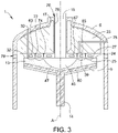
- the crystal growth apparatus 1 includes a housing 5 and a base 9 within the housing 5 for holding a solid silicon support 13.
- a pedestal 14 carries the base 9 and the solid silicon support 13. The pedestal 14 may rotate during crystal pulling to improve temperature and component gradients during crystal growth
- the crystal puller 1 includes a central vertical axis A that is parallel to the direction in which the ingot 15 is pulled.
- the puller 1 also includes a cooling jacket 19 that surrounds the ingot 15 to maintain preferred temperature gradients in the ingot 15.
- An open area 17 separates the cooling jacket from insulation 23.
- Other crystal puller arrangements may be used including embodiments in which a heat shield (not shown) at least partially surrounds the ingot 15 or in which the cooling jacket 19 is eliminated and the insulation 23 extends further toward the ingot 15. Regardless of the arrangement, an opening 78 is positioned near the ingot for entry of inert gas into the crucible puller system.
- the solid silicon support 13 is made of a multi-crystalline silicon billet, a single crystal silicon billet, or silicon plates.
- a "silicon support” is made of elemental silicon and is intended to exclude compounds of silicon (e.g., silica, silicon carbide).
- the solid silicon support 13 may include various impurities; however, the amount of impurities should not exceed an amount that degrades the quality of the silicon ingot below acceptable levels.
- the solid silicon support 13 includes a top surface 24 that is shaped for holding three pools of silicon material.
- the solid silicon support 13 may be shaped by targeting melting of the silicon support (e.g., in the crystal puller 1 or before placement into the puller 1) or by machining the silicon support.
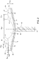
- the base 9 that holds the solid silicon support 13 has a center 62 ( Fig. 2 ) through which the vertical axis A passes and has a circumferential end 66. As shown in Figures 1 and 2 , the base 9 slants downward from the circumferential end 66 to its center 62. In other embodiments, the base does not slant downward (e.g., may be horizontal).
- the base 9 may be contoured to optimize the shape of the various molten pools described below and to improve crystal puller heat management.
- the top surface 24 includes at least three indentations for holding the molten silicon material - an annular silicon melting pool indentation 25, an annular stabilization pool indentation 41 and a growth pool indentation 47.
- An annular melting pool indentation 25 supports a silicon melting pool 27.
- Silicon is added through a feed inlet 30 to provide a continuous source of silicon material into the melting pool 27.
- Silicon may be added in solid form (e.g., granular silicon) in which the silicon melts within melting pool 27.
- a continuous feeder (not shown) may be used to supply granular silicon.
- a pre-melter (not shown) which may be internal or external to the crystal puller housing 5 may be used to supply molten silicon to the pool 27 in which case the molten silicon material is maintained in a melted state in the pool.
- the silicon support 13 includes the stabilization pool to allow silicon to fully melt and to maintain a consistent temperature before entering the growth pool 45.
- the solid silicon support 13 may also include more than three pools of silicon which may improve temperature and particle control but may add to the cost of the system.
- the silicon melting pool 27 is held between an outer peak 31 ( Fig. 2 ) and an inner peak 33 which define the indentation 25.
- the outer peak 31 may be part of an outer shelf 32 of the solid silicon support 13.
- the inner peak 33 is lower than the outer peak 31 relative to the vertical axis A to allow molten material to weir over the inner peak 33 and into the stabilization pool 39.
- the top surface 24 of the solid support 13 includes a stabilization pool outer peak 33 (which is the inner peak of the melting pool 27) and a stabilization pool inner peak 43 which define the annular stabilization indentation 41.
- the inner peak 43 is lower than the outer peak 31 of the melting pool indentation 25 relative to the vertical axis A to allow molten silicon to weir over the inner peak 43 and into the silicon growth pool 45.
- the inner peak 43 may be lower, at the same height or even higher than the stabilization pool outer peak 33.
- the relative heights between the inner peak 43 and stabilization pool outer peak 33 is altered during crystal pulling to change the dynamics of the puller system.
- the growth pool indentation 47 holds the molten silicon growth pool 45 from which an ingot 15 ( Fig. 1 ) is withdrawn.
- the growth pool indentation 47 that holds the growth pool 45 is formed within the stabilization pool inner peak 43.
- the melting pool indentation 25 has a width W 25 that extends from the outer peak 31 to the inner peak 33 and has a depth D 25 that is the vertical distance from its outer peak 31 to a bottom 52 of the indentation 25 (i.e., the lowest point of the indentation).
- the stabilization pool indentation 41 has a width W 41 that extends between its outer peak 33 and its inner peak 43 and has a depth D 41 that is the vertical distance from the outer peak 31 of the melting pool indentation 25 and a bottom 54 of the stabilization pool indentation 41.
- the growth pool indentation 47 had a width W 47 (i.e., diameter) and has a depth D 47 that is the vertical distance from the outer peak 31 of the melting pool indentation 25 to a bottom 56 of the growth pool indentation 47.
- the depth D 47 of the growth pool indentation 47 is greater than both the depths D 25 , D 41 of the melting pool indentation 25 and the stabilization pool indentation 41 to allow the growth pool indentation 47 to hold a larger volume of molten silicon.
- the depth D 47 of the growth pool indentation 47 may be at least about twice or even at least about three times the depths D 25 , D 41 of each of the melting pool indentation 25 and the stabilization pool indentation 41.
- the depth D 25 of the melting pool indentation 25, the depth D 41 of the stabilization pool indentation 41 and the depth D 47 of the growth pool indentation 47 may by controlled by the thermal gradients of the system which are chosen to produce stabile crystal growth.
- the width W 47 of the growth pool indentation 47 is greater than the widths W 25 , W 41 of the melting pool indentation 25 and the stabilization pool indentation 41 to provide for proper surface area to withdraw the ingot 15 ( Fig. 1 ) and to allow the growth pool to contain a sufficient volume of molten silicon.
- the width W 47 of the growth pool indentation 47 may be at least about twice or even at least about three times the widths W 25 , W 41 of each of the melting pool indentation 25 and the stabilization pool indentation 41.
- the melting pool indentation 25 and stabilization pool indentation 41 may have the same or different depths D 25 , D 41 and widths W 25 , W 41 .
- the solid silicon support 13 and silicon pools 27, 39, 45 and the ingot 15 are shown to illustrate use of the apparatus 1 and are not components of the apparatus unless stated otherwise.
- the silicon support 13 is part of the apparatus.
- the apparatus includes first, second and third annular heaters 63, 65, 67 for controlling the temperature profiles in the melting pool 27, stabilization pool 39 and growth pool 45, respectively.
- the first annular heater 63 is mounted above the melting pool 27 to melt granular silicon which is introduced into the pool 27 (or to maintain the silicon in a molten state when molten silicon is introduced into the pool).
- the first annular heater 63 may include an opening therein through which the solid or molten silicon passes.
- the second annular heater 65 Within this first annular heater 63 (i.e., within the central opening of the heater 63) is the second annular heater 65.
- the second annular heater 65 is mounted above the stabilization pool 39.
- the second annular heater 65 is controlled to maintain a consistent temperature of the silicon before entry into the growth pool 45 and to melt any solid silicon that weirs over from the melting pool 27.
- the third annular heater 67 is within the second annular heater 65 (within the central opening of the heater 65) and is mounted above the melting pool 45.
- the ingot 15 is withdrawn through the central opening of the third heater 67.
- the third heater 67 is controlled to maintain preferred temperature gradients in the ingot 15.
- the three heaters 63, 65, 67 are independently controlled to provide sufficient heat to the silicon melting pool 27, stabilization pool 39 and growth pool 45 without melting the solid silicon support 13.
- the heaters 63, 65, 67 should be spaced a distance from the pools 27, 39, 45 that provides proper melt and stabilization temperatures without the heaters causing melt contamination (e.g., through dipping of heaters in the melt) and without excess heat being communicated to adjacent heating zones (i.e., to adjacent pools).
- the heaters 63, 65, 67 may be resistance or RF heaters. While the heaters 63, 65, 67 may be described herein as being separate heaters, the heaters 63, 65, 67 may be combined in a single heating unit that allows three separate portions to be independently controlled to control heat input into the silicon melting pool 27, stabilization pool 39 and growth pool 45.
- Insulation 23 extends above the heaters 63, 65, 67.
- the ingot 15 is pulled upward through the insulation 23.
- An outer divider 72 extends downward from the insulation 23 between the first annular heater 63 and the second annular heater 65.
- An inner divider 74 also extends downward from the insulation between the second annular heater 65 and the third annular heater 67.
- a first gas inlet 76 is in fluid communication with the opening 78 in through which the ingot 15 is pulled. Gas travels downward around the ingot 15 and over the surface of the growth pool 45 and past the stabilization pool 39 and melting pool 27.
- the dividers 72, 74 extend circumferentially around the axis A of the crystal puller 1 and force gas to flow across the surfaces of the molten silicon at relatively high gas velocity to carry away particles such as dust from feeding of granular silicon and any cooled and precipitated silicon monoxide.
- the crystal puller 1 may include a second gas inlet 75 that discharges gas in the space formed between the outer divider 72 and the inner divider 74. Jets (not shown) may be used to direct gases across the surface of the growth pool 45, stabilization pool 39 and melting pool 27. Gases exit the system through an outlet 79 and may be cooled and further processed for re-use. The outlet 79 may be positioned at other portions of the crystal puller 1 such as at the bottom portion of the puller 1.
- Gases which may be used in the crystal puller 1 and introduced through the first inlet 76 and the optional second inlet 75 are gases that are inert with regard to silicon and may include argon, nitrogen or even krypton or helium.
- the base 9 may be composed of any material capable of supporting the solid silicon support 13 and silicon pools 27, 39, 45 at the temperatures and stresses of which the base 9 is typically exposed in crystal growing environments. Suitable materials may include silicon carbide, carbon, graphite, graphite insulation and refractory metals such as alumina or zirconia. While, in some embodiments, the base 9 may be eliminated and the solid silicon support 13 directly connected to the pedestal 14, it is generally preferred to incorporate a base 9 to provide sufficient structure and rigidity to the crystal pulling system.
- the base 9, support 13, insulation (if any) and heaters 63, 65, 67 should be configured to prevent the silicon pools 27, 39, 45 from extending to the base 9 while minimizing heat loss to reduce power consumption.
- the base 9 may include cooling channels 77 ( Fig. 2 ) formed therein for cooling the base 9 and the solid silicon support 13.
- the base 9 is in fluid contact with a cooling chamber 80 (i.e., cooling jacket) in which a cooling fluid is circulated to cool the base 9 and the solid silicon support 13.
- the apparatus does not include heaters or insulation below the base 9 to allow the base to properly cool. Insulation (not shown) may be included between the base 9 and the solid silicon support 13 to reduce heat loss.
- Heaters may be embedded in the solid silicon support 13 and, particularly, below the growth pool 45 to help maintain the growth pool 45 in a molten state. Such heaters may be resistive heaters or the silicon may be directly heated with inductively coupled RF heating. Temperature sensors (not shown) may be embedded in the base 9 or in the silicon support 13 to provide a temperature field that is used as feedback for power input for the heaters.
- the crystal puller 1 may be operated by continually (or intermittently) adding a source of silicon to the feed inlet 30 while the ingot is withdrawn from the growth pool 45.
- the crystal puller 1 may be operated in a semi-continuous state in which ingot growth is only stopped upon nearing the limit of weight for the ingot neck or the ingot nearing the full length of the pull chamber. Once ingot growth is stopped, the ingot is removed from the growth chamber and the puller is re-seeded and ingot growth is reinitiated.
- the silicon is melted after it falls within the melting pool 27.
- the silicon is maintained in its molten state in the pool 27.
- the first annular heater 63 is powered to melt silicon and/or maintain the added silicon in a molten state but not melt the solid silicon support 13 and including the inner peak 33 of the melting pool indentation 25. Addition of silicon into the pool 27 causes molten silicon to weir over the inner peak 33 ( Fig. 2 ) and into the stabilization pool 39.
- the second annular heater 65 is powered and controlled to maintain a consistent temperature in the stabilization pool 39 (e.g., through feedback from a field of temperature sensors) which allows for tighter temperature control in the growth pool 45. Silicon weirs over the stabilization pool inner peak 43 and into the growth pool 45.
- the third annular heater 67 is powered to control the convections and temperature gradients in the pool 45 for proper ingot growth.
- dopant may be added continuously with the silicon or may be added through a separate inlet (not shown).
- the first, second and third annular heaters 63, 65, 67 are powered continuously.
- the power supplied to the heaters 63, 65, 67 may be varied to control melting, stabilization and the growth conditions based on feedback from the temperature sensors. If the melting pool inner peak 33 or stabilization pool inner peak 43 is inadvertently melted, it may be reformed for proper transfer of silicon from the melting pool 27 into the stabilization pool 39 and into the growth pool 45.
- the base and solid silicon support allow the puller to be operated without a crucible (i.e., a container having a floor and sidewall that is conventionally composed of silica). As the molten silicon contacts the solid silicon support rather than a crucible (e.g., silica crucible containing oxygen), less or no oxygen enters the melt. Less oxygen is available to react with carbon to produce carbon oxides that are soluble in molten silicon. Less dissolved oxygen and carbon allow an ingot with less oxygen and carbon to be produced.
- Such ingots produced by embodiments of the present invention may have less than about 3 ppm of oxygen and, in some embodiments, the resulting ingot contains oxygen in an amount less than the detection limit of oxygen.
- the ingots may contain less than about 0.001 ppm of carbon and may even contain carbon in an amount below the detection limit of carbon.
- uniform axial and radial resistivity may be achieved through continuous doping. If oxygen is desired in the ingot, by not introducing oxygen into the system through the crucible, the melt may be doped with oxides to target and control grown-in oxygen.
- SiO silicon oxide
- Recued SiO in the system may allow some system components such as exhaust gas filtration systems, vacuum pumps and inert gas flow controllers to be reduced in size or eliminated.
- the system pressure is not required to be operated as low as in conventional systems (e.g., below 50 torr) in which the pressure is relatively low to allow oxygen to out-diffuse from the melt.
- the system may be operated at a higher pressure which allows the flow rate of inert gas (e.g., argon) to be reduced as more gas is present at the higher pressure.
- inert gas e.g., argon
- the crystal puller includes dividers that extend downward toward the melt
- the dividers act to force gas toward the surface of the melt and increase the velocity of the gas (which is sparse in vacuum systems) to move particles away from the growth pool, stabilization pool and melting pool.
- Use of a second gas inlet between an inner and outer divider helps maintain gas velocity as gas moves outward over the increasing crystal puller cross-section.
- the crystal puller includes a base which slants downward toward its center, the distances between the base and the growth pool, stabilization pool and melting pool may be more uniform which results in a more uniform heating of the pools.
- the term "about” when used in conjunction with ranges of dimensions, concentrations, temperatures or other physical or chemical properties or characteristics is meant to cover variations that may exist in the upper and/or lower limits of the ranges of the properties or characteristics, including, for example, variations resulting from rounding, measurement methodology or other statistical variation.
Landscapes
- Chemical & Material Sciences (AREA)
- Engineering & Computer Science (AREA)
- Crystallography & Structural Chemistry (AREA)
- Materials Engineering (AREA)
- Metallurgy (AREA)
- Organic Chemistry (AREA)
- Crystals, And After-Treatments Of Crystals (AREA)
Claims (14)
- Ein Kristallzüchtungsapparat (1) zur kontinuierlichen Herstellung eines Siliciumingots (15) aus einer Siliciumschmelze, wobei der Apparat eine vertikale Achse (A) hat und ein Siliciumingot relativ zu dieser vertikalen Achse nach oben gezogen wird, der Kristallzüchtungsapparat umfassend:eine Basis (9) mit einem festen Siliciumsupport (13), wobei der Support eine obere Oberfläche (24) hat, die so geformt ist, dass sie einen Siliciumschmelz-Pool (27), einen Siliciumstabilisierungs-Pool (39) und einen Siliciumwachstums-Pool (45) aufnehmen kann;einen Feed-Einlass (30) zur kontinuierlichen Gabe einer Quelle für Siliciummaterial in den Siliciumschmelz-Pool;einen ersten ringförmigen Heizer (63), der oberhalb des Siliciumschmelz-Pools angebracht ist, zum Schmelzen des Siliciummaterials oder um das Siliciummaterial in einem geschmolzenen Zustand zu halten;einen zweiten ringförmigen Heizer (65), der oberhalb des Siliciumstabilisierungs-Pools angebracht ist, wobei sich der zweite ringförmige Heizer innerhalb des ersten ringförmigen Heizers befindet; undmindestens einen dritten ringförmigen Heizer (67), der oberhalb des Siliciumwachstums-Pools angebracht ist, wobei sich der dritte ringförmige Heizer innerhalb des zweiten ringförmigen Heizers befindet.
- Der Kristallzüchtungsapparat gemäß Anspruch 1 wobei die Basis (9) eine Mitte (62) und eine Umfangskante (66) hat und die Basis so konturiert ist, dass sie zur Form von mindestens einem des Siliciumschmelz-Pools, Siliciumstabilisierungs-Pools und Siliciumwachstums-Pools passt, oder von der Umgangskante zur Mitte hin abschüssig ist.
- Der Kristallzüchtungsapparat gemäß irgendeinem der Ansprüche 1 bis 2 wobei der feste Siliciumsupport einen Schmelzpool-Außenrand (31) und einen Schmelzpool-Innenrand (33) besitzt, wobei der Innenrand relativ zur vertikalen Achse niedriger als der Außenrand ist, so dass geschmolzenes Silicium aus dem Siliciumschmelz-Pool über den Innenrand und in den Stabilisierungs-Pool überlaufen kann.
- Der Kristallzüchtungsapparat gemäß Anspruch 3 wobei der feste Support einen Stabilisierungspool-Außenrand (33)) und einen Stabilisierungspool-Innenrand (43), wobei der Innenrand relativ zur vertikalen Achse niedriger als der Außenrand ist, so dass geschmolzenes Silicium aus dem Siliciumstabilisierungs-Pool über den Innenrand und in den Siliciumwachstums-Pool überlaufen kann..
- Der Kristallzüchtungsapparat gemäß Anspruch 4 wobei der Schmelz-Pool-Innenrand und der Stabilisierungs-Pool-Außenrand derselbe Rand sind.
- Der Kristallzüchtungsapparat gemäß Anspruch 5 wobei der feste Support eine Wachstumspool-Vertiefung (47) besitzt, um den Siliciumwachstums-Pool aufzunehmen, wobei die Vertiefung sich innerhalb des Stabilisierungs-Pool-Innenrands befindet (43).
- Der Kristallzüchtungsapparat gemäß Anspruch 6 wobei der Schmelzpool-Außenrand (31) und -Innenrand (33) eine ringförmige Schmelzpool-Vertiefung (25) zwischen dem Außenrand und dem Innenrand bilden, wobei die Schmelzpool-Vertiefung eine Tiefe hat, welche die vertikale Distanz zwischen dem Außenrand und dem Grund der Schmelzpool-Vertiefung ist, wobei der Stabilisierungspool-Außenrand (33) und Stabilisierungspool-Innenrand (43) eine ringförmige Stabilisierungspool-Vertiefung (41) zwischen dem Außenrand und dem Innenrand bilden, wobei die Stabilisierungspool-Vertiefung eine Tiefe hat, welche die vertikale Distanz zwischen dem Schmelzpool-Außenrand und dem Grund der Stabilisierungspool-Vertiefung ist, wobei die Wachstumspool-Vertiefung (47) eine Tiefe hat, welche die vertikale Distanz zwischen dem Schmelzpool-Außenrand (31) und dem Grund der Wachstumspool-Vertiefung ist, wobei die Tiefe der Wachstumspool-Vertiefung größer ist als die Tiefe der Schmelzpool-Vertiefung und die Tiefe der Stabilisierungspool-Vertiefung.
- Der Kristallzüchtungsapparat gemäß irgendeinem der Ansprüche 1 bis 7 außerdem umfassend:eine Isolierung (23) welche sich oberhalb der Heizer erstreckt; undeinen Teiler (72) welcher sich von der Isolierung aus zwischen dem ersten ringförmigen Heizer und dem zweiten ringförmigen Heizer nach unten erstreckt, um Gas dazu zu zwingen, über eine Oberfläche des geschmolzenen Siliciums zu strömen.
- Der Kristallzüchtungsapparat gemäß Anspruch 8 wobei der Teiler ein äußerer Teiler (72), der Apparat außerdem umfassend einen inneren Teiler (74) welcher sich von der Isolierung aus zwischen dem zweiten ringförmigen Heizer und dem dritten ringförmigen Heizer nach unten erstreckt, um Gas dazu zu zwingen, über eine Oberfläche des geschmolzenen Siliciums zu strömen.
- Der Kristallzüchtungsapparat gemäß Anspruch 9 außerdem umfassend:einen ersten Gaseinlass (76) in fluider Kommunikation mit einer Öffnung (78) in der Isolierung, durch die der Ingot nach oben gezogen wird; undeinen zweiten Gaseinlass (75) welcher Gas in einen Zwischenraum zwischen dem äußeren Teiler und dem inneren Teiler abgibt.
- Der Kristallzüchtungsapparat gemäß irgendeinem der Ansprüche 1 bis 10 wobei (1) sich in der Basis Kühlkanäle (77) befinden, um die Basis zu kühlen, oder (2) die Basis in thermischem Kontakt mit einer Kühlkammer (80) ist, um einen Hitzeaustausch mit der Basis zu ermöglichen.
- Der Kristallzüchtungsapparat gemäß irgendeinem der Ansprüche 1 bis 11 wobei die Basis aus Siliciumcarbid, Kohlenstoff, Graphit, Graphitisolierung oder Refraktärmetallen besteht.
- Der Kristallzüchtungsapparat gemäß irgendeinem der Ansprüche 1 bis 12 wobei der Apparat keinen sauerstoffhaltigen Tiegel umfasst.
- Ein Verfahren zur Herstellung eines Siliciumingots im Apparat gemäß irgendeinem der Ansprüche 1 bis 13, das Verfahren umfassend:kontinuierliche Gabe einer Quelle für Siliciummaterial in den Siliciumschmelz-Pool;Betreiben des ersten ringförmigen Heizers, um Siliciummaterial zu schmelzen oder um das Siliciummaterial in einem geschmolzenen Zustand zu halten, wobei geschmolzenes Silicium über den Rand des Schmelzpools in den Stabilisierungs-Pool überläuft;Betreiben des zweiten ringförmigen Heizers, um eine Temperatur im Stabilisierungs-Pool aufrechtzuerhalten, wobei geschmolzenes Silicium über den Rand des Stabilisierungs-Pools und in den Wachstums-Pool überläuft; undBetreiben des dritten ringförmigen Heizers, um die Ingot-Wachstumsbedingungen einzustellen, wobei der Ingot nach oben aus dem Wachstumspool gezogen wird.
Applications Claiming Priority (2)
| Application Number | Priority Date | Filing Date | Title |
|---|---|---|---|
| US201662314562P | 2016-03-29 | 2016-03-29 | |
| PCT/US2017/024091 WO2017172530A1 (en) | 2016-03-29 | 2017-03-24 | Crystal growth apparatus and related methods |
Publications (2)
| Publication Number | Publication Date |
|---|---|
| EP3436624A1 EP3436624A1 (de) | 2019-02-06 |
| EP3436624B1 true EP3436624B1 (de) | 2022-11-30 |
Family
ID=58464703
Family Applications (1)
| Application Number | Title | Priority Date | Filing Date |
|---|---|---|---|
| EP17715374.9A Active EP3436624B1 (de) | 2016-03-29 | 2017-03-24 | Kristallzüchtungsvorrichtung und zugehörige verfahren |
Country Status (9)
| Country | Link |
|---|---|
| US (1) | US20190085480A1 (de) |
| EP (1) | EP3436624B1 (de) |
| JP (1) | JP6908620B2 (de) |
| KR (1) | KR102338006B1 (de) |
| CN (1) | CN108884587A (de) |
| DE (1) | DE112017001711B4 (de) |
| MY (1) | MY191240A (de) |
| SA (1) | SA518400107B1 (de) |
| WO (1) | WO2017172530A1 (de) |
Family Cites Families (11)
| Publication number | Priority date | Publication date | Assignee | Title |
|---|---|---|---|---|
| GB911360A (en) * | 1959-10-16 | 1962-11-28 | Westinghouse Electric Corp | Process for growing crystals |
| GB1225405A (de) * | 1967-08-08 | 1971-03-17 | ||
| US4650540A (en) | 1975-07-09 | 1987-03-17 | Milton Stoll | Methods and apparatus for producing coherent or monolithic elements |
| JPH03199192A (ja) * | 1989-12-27 | 1991-08-30 | Toshiba Corp | シリコン単結晶引上げ用ルツボ |
| JPH054888A (ja) * | 1991-06-26 | 1993-01-14 | Nkk Corp | シリコン単結晶の製造装置 |
| DE19628851A1 (de) * | 1996-07-17 | 1998-01-22 | Wacker Siltronic Halbleitermat | Verfahren und Vorrichtung zur Herstellung eines Einkristalls |
| US7635414B2 (en) * | 2003-11-03 | 2009-12-22 | Solaicx, Inc. | System for continuous growing of monocrystalline silicon |
| WO2011063795A1 (de) | 2009-11-24 | 2011-06-03 | Forschungsverbund Berlin E. V. | Verfahren und vorrichtung zur herstellung von einkristallen aus halbleitermaterial |
| US9376762B2 (en) * | 2012-11-29 | 2016-06-28 | Solaicx | Weir for improved crystal growth in a continuous Czochralski process |
| US20140261155A1 (en) | 2013-03-15 | 2014-09-18 | Memc Electronic Materials, Inc. | Crucible for controlling oxygen and related methods |
| KR101467103B1 (ko) * | 2013-06-21 | 2014-11-28 | 주식회사 엘지실트론 | 실리콘 단결정 성장 장치 및 그 성장 방법 |
-
2017
- 2017-03-24 EP EP17715374.9A patent/EP3436624B1/de active Active
- 2017-03-24 US US16/084,297 patent/US20190085480A1/en not_active Abandoned
- 2017-03-24 DE DE112017001711.4T patent/DE112017001711B4/de active Active
- 2017-03-24 MY MYPI2018703481A patent/MY191240A/en unknown
- 2017-03-24 CN CN201780021256.2A patent/CN108884587A/zh active Pending
- 2017-03-24 JP JP2018550720A patent/JP6908620B2/ja active Active
- 2017-03-24 KR KR1020187030725A patent/KR102338006B1/ko active Active
- 2017-03-24 WO PCT/US2017/024091 patent/WO2017172530A1/en not_active Ceased
-
2018
- 2018-09-25 SA SA518400107A patent/SA518400107B1/ar unknown
Also Published As
| Publication number | Publication date |
|---|---|
| DE112017001711B4 (de) | 2022-05-19 |
| EP3436624A1 (de) | 2019-02-06 |
| DE112017001711T5 (de) | 2018-12-20 |
| KR102338006B1 (ko) | 2021-12-10 |
| SA518400107B1 (ar) | 2022-09-25 |
| MY191240A (en) | 2022-06-10 |
| KR20180126545A (ko) | 2018-11-27 |
| JP6908620B2 (ja) | 2021-07-28 |
| JP2019509970A (ja) | 2019-04-11 |
| CN108884587A (zh) | 2018-11-23 |
| WO2017172530A1 (en) | 2017-10-05 |
| US20190085480A1 (en) | 2019-03-21 |
Similar Documents
| Publication | Publication Date | Title |
|---|---|---|
| US7635414B2 (en) | System for continuous growing of monocrystalline silicon | |
| US4659421A (en) | System for growth of single crystal materials with extreme uniformity in their structural and electrical properties | |
| EP3565918A1 (de) | Kristallziehsystem und -verfahren einschliesslich tiegel und konditionierungselementen | |
| EP2971275B1 (de) | Tiegelanordnung zur sauerstoffsteuerung und zugehörige verfahren | |
| EP3617351B1 (de) | Vorrichtung und verfahren zur horizontalen züchtung eines siliziumwafers | |
| EP2971274A1 (de) | Czochralski-tiegel zur sauerstoffsteuerung und zugehörige verfahren | |
| WO2014094157A1 (en) | A method and apparatus for melting aluminum oxide | |
| TWI598475B (zh) | 在連續柴可斯基(czochralski)方法中用於改良晶體成長之堰 | |
| WO2014085388A1 (en) | Heat shield for improved continuous czochralski process | |
| JP4389574B2 (ja) | SiC単結晶の製造方法および製造装置 | |
| US20200255971A1 (en) | Methods for recycling monocrystalline segments cut from a monocrystalline ingot | |
| US20080060572A1 (en) | Magnetic Field Applied Pulling Method for Pulling Silicon Single Crystal | |
| CN106715764B (zh) | 允许杂质稀释的穿过堰体的通路的设计方法 | |
| US20190085480A1 (en) | Crystal Growth Apparatus and Related Methods | |
| EP4208589B1 (de) | Kristallziehsysteme mit einem abdeckelement zum abdecken der siliciumladung und verfahren zum züchten einer siliciumschmelze in einer tiegelanordnung | |
| US10060046B2 (en) | Crystal puller for inhibiting melt contamination | |
| KR101467075B1 (ko) | 잉곳 성장 장치 및 잉곳 성장 방법 | |
| US12221718B2 (en) | Systems and methods for controlling a gas dopant vaporization rate during a crystal growth process | |
| US12195871B2 (en) | Systems and methods for controlling a gas dopant vaporization rate during a crystal growth process | |
| US20250092560A1 (en) | Systems and methods for controlling a gas dopant vaporization rate during a crystal growth process | |
| JP2013112539A (ja) | シリコンインゴットの連続鋳造方法 | |
| JP2017193469A (ja) | アフターヒータ及びサファイア単結晶製造装置 | |
| KR20230150326A (ko) | 복합 배기 튜브를 갖는 잉곳 견인기 장치 및 하부 및 상부 배기 튜브 부분들의 길이들을 선택하기 위한 방법들 | |
| JP2003117638A (ja) | 薄板製造装置および太陽電池 | |
| Rudolph | Growth Of Si Crystals in Rectangular Shape for the Solar Cell Application |
Legal Events
| Date | Code | Title | Description |
|---|---|---|---|
| STAA | Information on the status of an ep patent application or granted ep patent |
Free format text: STATUS: UNKNOWN |
|
| STAA | Information on the status of an ep patent application or granted ep patent |
Free format text: STATUS: THE INTERNATIONAL PUBLICATION HAS BEEN MADE |
|
| PUAI | Public reference made under article 153(3) epc to a published international application that has entered the european phase |
Free format text: ORIGINAL CODE: 0009012 |
|
| STAA | Information on the status of an ep patent application or granted ep patent |
Free format text: STATUS: REQUEST FOR EXAMINATION WAS MADE |
|
| 17P | Request for examination filed |
Effective date: 20181026 |
|
| AK | Designated contracting states |
Kind code of ref document: A1 Designated state(s): AL AT BE BG CH CY CZ DE DK EE ES FI FR GB GR HR HU IE IS IT LI LT LU LV MC MK MT NL NO PL PT RO RS SE SI SK SM TR |
|
| AX | Request for extension of the european patent |
Extension state: BA ME |
|
| DAV | Request for validation of the european patent (deleted) | ||
| DAX | Request for extension of the european patent (deleted) | ||
| RAP1 | Party data changed (applicant data changed or rights of an application transferred) |
Owner name: CORNER STAR LIMITED |
|
| STAA | Information on the status of an ep patent application or granted ep patent |
Free format text: STATUS: EXAMINATION IS IN PROGRESS |
|
| 17Q | First examination report despatched |
Effective date: 20210201 |
|
| GRAP | Despatch of communication of intention to grant a patent |
Free format text: ORIGINAL CODE: EPIDOSNIGR1 |
|
| STAA | Information on the status of an ep patent application or granted ep patent |
Free format text: STATUS: GRANT OF PATENT IS INTENDED |
|
| INTG | Intention to grant announced |
Effective date: 20220610 |
|
| GRAS | Grant fee paid |
Free format text: ORIGINAL CODE: EPIDOSNIGR3 |
|
| GRAA | (expected) grant |
Free format text: ORIGINAL CODE: 0009210 |
|
| STAA | Information on the status of an ep patent application or granted ep patent |
Free format text: STATUS: THE PATENT HAS BEEN GRANTED |
|
| AK | Designated contracting states |
Kind code of ref document: B1 Designated state(s): AL AT BE BG CH CY CZ DE DK EE ES FI FR GB GR HR HU IE IS IT LI LT LU LV MC MK MT NL NO PL PT RO RS SE SI SK SM TR |
|
| REG | Reference to a national code |
Ref country code: CH Ref legal event code: EP Ref country code: GB Ref legal event code: FG4D |
|
| REG | Reference to a national code |
Ref country code: AT Ref legal event code: REF Ref document number: 1534743 Country of ref document: AT Kind code of ref document: T Effective date: 20221215 Ref country code: DE Ref legal event code: R096 Ref document number: 602017064095 Country of ref document: DE |
|
| REG | Reference to a national code |
Ref country code: IE Ref legal event code: FG4D |
|
| REG | Reference to a national code |
Ref country code: NO Ref legal event code: T2 Effective date: 20221130 |
|
| REG | Reference to a national code |
Ref country code: LT Ref legal event code: MG9D |
|
| REG | Reference to a national code |
Ref country code: NL Ref legal event code: MP Effective date: 20221130 |
|
| PG25 | Lapsed in a contracting state [announced via postgrant information from national office to epo] |
Ref country code: SE Free format text: LAPSE BECAUSE OF FAILURE TO SUBMIT A TRANSLATION OF THE DESCRIPTION OR TO PAY THE FEE WITHIN THE PRESCRIBED TIME-LIMIT Effective date: 20221130 Ref country code: PT Free format text: LAPSE BECAUSE OF FAILURE TO SUBMIT A TRANSLATION OF THE DESCRIPTION OR TO PAY THE FEE WITHIN THE PRESCRIBED TIME-LIMIT Effective date: 20230331 Ref country code: LT Free format text: LAPSE BECAUSE OF FAILURE TO SUBMIT A TRANSLATION OF THE DESCRIPTION OR TO PAY THE FEE WITHIN THE PRESCRIBED TIME-LIMIT Effective date: 20221130 Ref country code: FI Free format text: LAPSE BECAUSE OF FAILURE TO SUBMIT A TRANSLATION OF THE DESCRIPTION OR TO PAY THE FEE WITHIN THE PRESCRIBED TIME-LIMIT Effective date: 20221130 Ref country code: ES Free format text: LAPSE BECAUSE OF FAILURE TO SUBMIT A TRANSLATION OF THE DESCRIPTION OR TO PAY THE FEE WITHIN THE PRESCRIBED TIME-LIMIT Effective date: 20221130 |
|
| REG | Reference to a national code |
Ref country code: AT Ref legal event code: MK05 Ref document number: 1534743 Country of ref document: AT Kind code of ref document: T Effective date: 20221130 |
|
| PG25 | Lapsed in a contracting state [announced via postgrant information from national office to epo] |
Ref country code: RS Free format text: LAPSE BECAUSE OF FAILURE TO SUBMIT A TRANSLATION OF THE DESCRIPTION OR TO PAY THE FEE WITHIN THE PRESCRIBED TIME-LIMIT Effective date: 20221130 Ref country code: PL Free format text: LAPSE BECAUSE OF FAILURE TO SUBMIT A TRANSLATION OF THE DESCRIPTION OR TO PAY THE FEE WITHIN THE PRESCRIBED TIME-LIMIT Effective date: 20221130 Ref country code: LV Free format text: LAPSE BECAUSE OF FAILURE TO SUBMIT A TRANSLATION OF THE DESCRIPTION OR TO PAY THE FEE WITHIN THE PRESCRIBED TIME-LIMIT Effective date: 20221130 Ref country code: IS Free format text: LAPSE BECAUSE OF FAILURE TO SUBMIT A TRANSLATION OF THE DESCRIPTION OR TO PAY THE FEE WITHIN THE PRESCRIBED TIME-LIMIT Effective date: 20230330 Ref country code: HR Free format text: LAPSE BECAUSE OF FAILURE TO SUBMIT A TRANSLATION OF THE DESCRIPTION OR TO PAY THE FEE WITHIN THE PRESCRIBED TIME-LIMIT Effective date: 20221130 Ref country code: GR Free format text: LAPSE BECAUSE OF FAILURE TO SUBMIT A TRANSLATION OF THE DESCRIPTION OR TO PAY THE FEE WITHIN THE PRESCRIBED TIME-LIMIT Effective date: 20230301 |
|
| PG25 | Lapsed in a contracting state [announced via postgrant information from national office to epo] |
Ref country code: NL Free format text: LAPSE BECAUSE OF FAILURE TO SUBMIT A TRANSLATION OF THE DESCRIPTION OR TO PAY THE FEE WITHIN THE PRESCRIBED TIME-LIMIT Effective date: 20221130 |
|
| P01 | Opt-out of the competence of the unified patent court (upc) registered |
Effective date: 20230526 |
|
| PG25 | Lapsed in a contracting state [announced via postgrant information from national office to epo] |
Ref country code: SM Free format text: LAPSE BECAUSE OF FAILURE TO SUBMIT A TRANSLATION OF THE DESCRIPTION OR TO PAY THE FEE WITHIN THE PRESCRIBED TIME-LIMIT Effective date: 20221130 Ref country code: RO Free format text: LAPSE BECAUSE OF FAILURE TO SUBMIT A TRANSLATION OF THE DESCRIPTION OR TO PAY THE FEE WITHIN THE PRESCRIBED TIME-LIMIT Effective date: 20221130 Ref country code: EE Free format text: LAPSE BECAUSE OF FAILURE TO SUBMIT A TRANSLATION OF THE DESCRIPTION OR TO PAY THE FEE WITHIN THE PRESCRIBED TIME-LIMIT Effective date: 20221130 Ref country code: DK Free format text: LAPSE BECAUSE OF FAILURE TO SUBMIT A TRANSLATION OF THE DESCRIPTION OR TO PAY THE FEE WITHIN THE PRESCRIBED TIME-LIMIT Effective date: 20221130 Ref country code: CZ Free format text: LAPSE BECAUSE OF FAILURE TO SUBMIT A TRANSLATION OF THE DESCRIPTION OR TO PAY THE FEE WITHIN THE PRESCRIBED TIME-LIMIT Effective date: 20221130 Ref country code: AT Free format text: LAPSE BECAUSE OF FAILURE TO SUBMIT A TRANSLATION OF THE DESCRIPTION OR TO PAY THE FEE WITHIN THE PRESCRIBED TIME-LIMIT Effective date: 20221130 |
|
| PG25 | Lapsed in a contracting state [announced via postgrant information from national office to epo] |
Ref country code: SK Free format text: LAPSE BECAUSE OF FAILURE TO SUBMIT A TRANSLATION OF THE DESCRIPTION OR TO PAY THE FEE WITHIN THE PRESCRIBED TIME-LIMIT Effective date: 20221130 Ref country code: AL Free format text: LAPSE BECAUSE OF FAILURE TO SUBMIT A TRANSLATION OF THE DESCRIPTION OR TO PAY THE FEE WITHIN THE PRESCRIBED TIME-LIMIT Effective date: 20221130 |
|
| REG | Reference to a national code |
Ref country code: DE Ref legal event code: R097 Ref document number: 602017064095 Country of ref document: DE |
|
| PLBE | No opposition filed within time limit |
Free format text: ORIGINAL CODE: 0009261 |
|
| STAA | Information on the status of an ep patent application or granted ep patent |
Free format text: STATUS: NO OPPOSITION FILED WITHIN TIME LIMIT |
|
| PG25 | Lapsed in a contracting state [announced via postgrant information from national office to epo] |
Ref country code: MC Free format text: LAPSE BECAUSE OF FAILURE TO SUBMIT A TRANSLATION OF THE DESCRIPTION OR TO PAY THE FEE WITHIN THE PRESCRIBED TIME-LIMIT Effective date: 20221130 |
|
| REG | Reference to a national code |
Ref country code: CH Ref legal event code: PL |
|
| 26N | No opposition filed |
Effective date: 20230831 |
|
| PG25 | Lapsed in a contracting state [announced via postgrant information from national office to epo] |
Ref country code: SI Free format text: LAPSE BECAUSE OF FAILURE TO SUBMIT A TRANSLATION OF THE DESCRIPTION OR TO PAY THE FEE WITHIN THE PRESCRIBED TIME-LIMIT Effective date: 20221130 |
|
| REG | Reference to a national code |
Ref country code: BE Ref legal event code: MM Effective date: 20230331 |
|
| PG25 | Lapsed in a contracting state [announced via postgrant information from national office to epo] |
Ref country code: LU Free format text: LAPSE BECAUSE OF NON-PAYMENT OF DUE FEES Effective date: 20230324 |
|
| REG | Reference to a national code |
Ref country code: IE Ref legal event code: MM4A |
|
| PG25 | Lapsed in a contracting state [announced via postgrant information from national office to epo] |
Ref country code: LI Free format text: LAPSE BECAUSE OF NON-PAYMENT OF DUE FEES Effective date: 20230331 Ref country code: IE Free format text: LAPSE BECAUSE OF NON-PAYMENT OF DUE FEES Effective date: 20230324 Ref country code: CH Free format text: LAPSE BECAUSE OF NON-PAYMENT OF DUE FEES Effective date: 20230331 |
|
| PG25 | Lapsed in a contracting state [announced via postgrant information from national office to epo] |
Ref country code: BE Free format text: LAPSE BECAUSE OF NON-PAYMENT OF DUE FEES Effective date: 20230331 |
|
| PG25 | Lapsed in a contracting state [announced via postgrant information from national office to epo] |
Ref country code: BG Free format text: LAPSE BECAUSE OF FAILURE TO SUBMIT A TRANSLATION OF THE DESCRIPTION OR TO PAY THE FEE WITHIN THE PRESCRIBED TIME-LIMIT Effective date: 20221130 |
|
| PG25 | Lapsed in a contracting state [announced via postgrant information from national office to epo] |
Ref country code: BG Free format text: LAPSE BECAUSE OF FAILURE TO SUBMIT A TRANSLATION OF THE DESCRIPTION OR TO PAY THE FEE WITHIN THE PRESCRIBED TIME-LIMIT Effective date: 20221130 |
|
| PG25 | Lapsed in a contracting state [announced via postgrant information from national office to epo] |
Ref country code: CY Free format text: LAPSE BECAUSE OF FAILURE TO SUBMIT A TRANSLATION OF THE DESCRIPTION OR TO PAY THE FEE WITHIN THE PRESCRIBED TIME-LIMIT; INVALID AB INITIO Effective date: 20170324 |
|
| PG25 | Lapsed in a contracting state [announced via postgrant information from national office to epo] |
Ref country code: HU Free format text: LAPSE BECAUSE OF FAILURE TO SUBMIT A TRANSLATION OF THE DESCRIPTION OR TO PAY THE FEE WITHIN THE PRESCRIBED TIME-LIMIT; INVALID AB INITIO Effective date: 20170324 |
|
| PG25 | Lapsed in a contracting state [announced via postgrant information from national office to epo] |
Ref country code: TR Free format text: LAPSE BECAUSE OF FAILURE TO SUBMIT A TRANSLATION OF THE DESCRIPTION OR TO PAY THE FEE WITHIN THE PRESCRIBED TIME-LIMIT Effective date: 20221130 |
|
| PGFP | Annual fee paid to national office [announced via postgrant information from national office to epo] |
Ref country code: GB Payment date: 20260323 Year of fee payment: 10 |
|
| PGFP | Annual fee paid to national office [announced via postgrant information from national office to epo] |
Ref country code: NO Payment date: 20260226 Year of fee payment: 10 Ref country code: DE Payment date: 20260313 Year of fee payment: 10 |
|
| PGFP | Annual fee paid to national office [announced via postgrant information from national office to epo] |
Ref country code: IT Payment date: 20260309 Year of fee payment: 10 |
|
| PGFP | Annual fee paid to national office [announced via postgrant information from national office to epo] |
Ref country code: FR Payment date: 20260330 Year of fee payment: 10 |