EP3436307B1 - Projecteur de véhicule - Google Patents
Projecteur de véhicule Download PDFInfo
- Publication number
- EP3436307B1 EP3436307B1 EP17716952.1A EP17716952A EP3436307B1 EP 3436307 B1 EP3436307 B1 EP 3436307B1 EP 17716952 A EP17716952 A EP 17716952A EP 3436307 B1 EP3436307 B1 EP 3436307B1
- Authority
- EP
- European Patent Office
- Prior art keywords
- modules
- complementary
- lighting
- module
- main
- Prior art date
- Legal status (The legal status is an assumption and is not a legal conclusion. Google has not performed a legal analysis and makes no representation as to the accuracy of the status listed.)
- Active
Links
Images

Classifications
-
- B—PERFORMING OPERATIONS; TRANSPORTING
- B60—VEHICLES IN GENERAL
- B60Q—ARRANGEMENT OF SIGNALLING OR LIGHTING DEVICES, THE MOUNTING OR SUPPORTING THEREOF OR CIRCUITS THEREFOR, FOR VEHICLES IN GENERAL
- B60Q1/00—Arrangement of optical signalling or lighting devices, the mounting or supporting thereof or circuits therefor
- B60Q1/02—Arrangement of optical signalling or lighting devices, the mounting or supporting thereof or circuits therefor the devices being primarily intended to illuminate the way ahead or to illuminate other areas of way or environments
- B60Q1/04—Arrangement of optical signalling or lighting devices, the mounting or supporting thereof or circuits therefor the devices being primarily intended to illuminate the way ahead or to illuminate other areas of way or environments the devices being headlights
- B60Q1/06—Arrangement of optical signalling or lighting devices, the mounting or supporting thereof or circuits therefor the devices being primarily intended to illuminate the way ahead or to illuminate other areas of way or environments the devices being headlights adjustable, e.g. remotely-controlled from inside vehicle
- B60Q1/08—Arrangement of optical signalling or lighting devices, the mounting or supporting thereof or circuits therefor the devices being primarily intended to illuminate the way ahead or to illuminate other areas of way or environments the devices being headlights adjustable, e.g. remotely-controlled from inside vehicle automatically
- B60Q1/085—Arrangement of optical signalling or lighting devices, the mounting or supporting thereof or circuits therefor the devices being primarily intended to illuminate the way ahead or to illuminate other areas of way or environments the devices being headlights adjustable, e.g. remotely-controlled from inside vehicle automatically due to special conditions, e.g. adverse weather, type of road, badly illuminated road signs or potential dangers
-
- B—PERFORMING OPERATIONS; TRANSPORTING
- B60—VEHICLES IN GENERAL
- B60Q—ARRANGEMENT OF SIGNALLING OR LIGHTING DEVICES, THE MOUNTING OR SUPPORTING THEREOF OR CIRCUITS THEREFOR, FOR VEHICLES IN GENERAL
- B60Q1/00—Arrangement of optical signalling or lighting devices, the mounting or supporting thereof or circuits therefor
- B60Q1/02—Arrangement of optical signalling or lighting devices, the mounting or supporting thereof or circuits therefor the devices being primarily intended to illuminate the way ahead or to illuminate other areas of way or environments
- B60Q1/04—Arrangement of optical signalling or lighting devices, the mounting or supporting thereof or circuits therefor the devices being primarily intended to illuminate the way ahead or to illuminate other areas of way or environments the devices being headlights
- B60Q1/06—Arrangement of optical signalling or lighting devices, the mounting or supporting thereof or circuits therefor the devices being primarily intended to illuminate the way ahead or to illuminate other areas of way or environments the devices being headlights adjustable, e.g. remotely-controlled from inside vehicle
- B60Q1/08—Arrangement of optical signalling or lighting devices, the mounting or supporting thereof or circuits therefor the devices being primarily intended to illuminate the way ahead or to illuminate other areas of way or environments the devices being headlights adjustable, e.g. remotely-controlled from inside vehicle automatically
- B60Q1/12—Arrangement of optical signalling or lighting devices, the mounting or supporting thereof or circuits therefor the devices being primarily intended to illuminate the way ahead or to illuminate other areas of way or environments the devices being headlights adjustable, e.g. remotely-controlled from inside vehicle automatically due to steering position
-
- B—PERFORMING OPERATIONS; TRANSPORTING
- B60—VEHICLES IN GENERAL
- B60Q—ARRANGEMENT OF SIGNALLING OR LIGHTING DEVICES, THE MOUNTING OR SUPPORTING THEREOF OR CIRCUITS THEREFOR, FOR VEHICLES IN GENERAL
- B60Q1/00—Arrangement of optical signalling or lighting devices, the mounting or supporting thereof or circuits therefor
- B60Q1/02—Arrangement of optical signalling or lighting devices, the mounting or supporting thereof or circuits therefor the devices being primarily intended to illuminate the way ahead or to illuminate other areas of way or environments
- B60Q1/04—Arrangement of optical signalling or lighting devices, the mounting or supporting thereof or circuits therefor the devices being primarily intended to illuminate the way ahead or to illuminate other areas of way or environments the devices being headlights
- B60Q1/18—Arrangement of optical signalling or lighting devices, the mounting or supporting thereof or circuits therefor the devices being primarily intended to illuminate the way ahead or to illuminate other areas of way or environments the devices being headlights being additional front lights
-
- B—PERFORMING OPERATIONS; TRANSPORTING
- B60—VEHICLES IN GENERAL
- B60Q—ARRANGEMENT OF SIGNALLING OR LIGHTING DEVICES, THE MOUNTING OR SUPPORTING THEREOF OR CIRCUITS THEREFOR, FOR VEHICLES IN GENERAL
- B60Q2300/00—Indexing codes for automatically adjustable headlamps or automatically dimmable headlamps
- B60Q2300/10—Indexing codes relating to particular vehicle conditions
- B60Q2300/11—Linear movements of the vehicle
- B60Q2300/112—Vehicle speed
-
- B—PERFORMING OPERATIONS; TRANSPORTING
- B60—VEHICLES IN GENERAL
- B60Q—ARRANGEMENT OF SIGNALLING OR LIGHTING DEVICES, THE MOUNTING OR SUPPORTING THEREOF OR CIRCUITS THEREFOR, FOR VEHICLES IN GENERAL
- B60Q2300/00—Indexing codes for automatically adjustable headlamps or automatically dimmable headlamps
- B60Q2300/10—Indexing codes relating to particular vehicle conditions
- B60Q2300/12—Steering parameters
- B60Q2300/122—Steering angle
-
- B—PERFORMING OPERATIONS; TRANSPORTING
- B60—VEHICLES IN GENERAL
- B60Q—ARRANGEMENT OF SIGNALLING OR LIGHTING DEVICES, THE MOUNTING OR SUPPORTING THEREOF OR CIRCUITS THEREFOR, FOR VEHICLES IN GENERAL
- B60Q2300/00—Indexing codes for automatically adjustable headlamps or automatically dimmable headlamps
- B60Q2300/30—Indexing codes relating to the vehicle environment
- B60Q2300/31—Atmospheric conditions
- B60Q2300/312—Adverse weather
-
- B—PERFORMING OPERATIONS; TRANSPORTING
- B60—VEHICLES IN GENERAL
- B60Q—ARRANGEMENT OF SIGNALLING OR LIGHTING DEVICES, THE MOUNTING OR SUPPORTING THEREOF OR CIRCUITS THEREFOR, FOR VEHICLES IN GENERAL
- B60Q2300/00—Indexing codes for automatically adjustable headlamps or automatically dimmable headlamps
- B60Q2300/30—Indexing codes relating to the vehicle environment
- B60Q2300/33—Driving situation
- B60Q2300/331—Driving situation characterised by the driving side, e.g. on the left or right hand side
-
- B—PERFORMING OPERATIONS; TRANSPORTING
- B60—VEHICLES IN GENERAL
- B60Q—ARRANGEMENT OF SIGNALLING OR LIGHTING DEVICES, THE MOUNTING OR SUPPORTING THEREOF OR CIRCUITS THEREFOR, FOR VEHICLES IN GENERAL
- B60Q2300/00—Indexing codes for automatically adjustable headlamps or automatically dimmable headlamps
- B60Q2300/40—Indexing codes relating to other road users or special conditions
- B60Q2300/45—Special conditions, e.g. pedestrians, road signs or potential dangers
Definitions
- the present invention generally relates to a headlamp intended to be mounted on a motor vehicle.
- a lighting module emits a single type of beam so that the photometry of the projector, that is to say the illuminated area in front of the vehicle, is static whatever the traffic condition unless using an element such as a mask, a screen or even a barrel which makes the system and its manufacture more complicated.
- JP2005088856A a headlamp comprising a main module producing a low beam and three adjacent fixed complementary modules switched on successively in a bend. . This document does not make it possible to ensure modular photometry with a wide variety of lighting configurations.
- a projector comprising a main module for low beam and two complementary modules that can be oriented in azimuth.
- the two complementary modules together produce a variable complementary beam intended to complete the main beam to produce an adaptive high beam, a bend beam and a motorway beam as required.
- the elevation position of the beams of each of the complementary modules can be modified by relative displacement of the light source and of an optic inside the module.
- An object of the present invention is to respond to the drawbacks of the prior art documents mentioned above and in particular, first of all, to provide an economical vehicle headlight, simple to implement and capable of providing photometry modular and combining multiple functionalities at optimal performance levels.
- a first aspect of the invention relates to a headlamp characterized by the characterizing part of claim 1
- control unit is able to control the intensity of the lighting of the complementary modules so that the first complementary module lights up instantaneously at maximum intensity then the second then the third so as to provide a field of vision maximum night time to the driver of the vehicle during the turn.
- the unit controls the modules starting from the innermost module in the bend towards the main module, so that they gradually turn off until the exit from the bend.
- all the additional modules are switched on simultaneously at maximum power as soon as an angle of rotation of the steering wheel is detected and/or the activation of the direction indicator.
- a fourth aspect of the invention relates to a motor vehicle comprising at least one vehicle headlamp as described above.
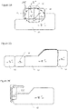
- the figure 1 shows a vehicle headlamp 1 according to an embodiment of the present invention.
- this headlamp comprises a main module 2, 2', 2" arranged to emit a main beam of light 31, 41, 45, 51, 61, 71, preferably a 2" main beam/dipped beam 2, 2', that is to say that it is a bi-function module which can emit a beam of low beam or a beam of high beam, which comprises one or more motors (not visible) arranged to adjust it in elevation and in azimuth according to the vertical and horizontal arrows of the figure 1 .
- the main dipped beam can have a flat cut-off, i.e. its photometry (illumination zone) is essentially rectangular without an enlarged illumination zone for the side of the road or with a cut-off at X° (for example 15°) so that the main beam also illuminates the lower side of the road.
- this projector comprises a plurality of complementary modules 3, 3', 3" each arranged to emit a complementary light beam 34, 44, 54, 74; 33, 43, 53, 73; 32, 42, 52, 62, 72, different from the main beam of light 41, 45, 51, 61, 71.
- the complementary modules 3, 3', 3" comprise each preferably a motor arranged to adjust the complementary module for which it is intended in elevation and in azimuth independently of each other as represented by the vertical and horizontal arrows.
- the projector 1 also comprises an adjustment means 4, which may include the previously mentioned motors, to adjust in elevation and in azimuth each of the lighting modules 2, 2', 2", 3, 3', 3" , main and complementary, and a control unit 5 to issue an order to the adjustment means 4 to orient each of the lighting modules 2, 2', 2", 3, 3', 3" in elevation and in azimuth independently of the each other and control the light intensity of each module also independently of each other.
- an adjustment means 4 which may include the previously mentioned motors, to adjust in elevation and in azimuth each of the lighting modules 2, 2', 2", 3, 3', 3" , main and complementary
- a control unit 5 to issue an order to the adjustment means 4 to orient each of the lighting modules 2, 2', 2", 3, 3', 3" in elevation and in azimuth independently of the each other and control the light intensity of each module also independently of each other.
- the figures 2A and 2B represent a particular embodiment of the present invention in which the main lighting module 2 is arranged to emit a beam of light 31 with a flat cut-off to emit a dipped beam (or dipped beam)”.
- the beam of the main module does not illuminate an additional zone on the lower side of the road further forward than the rest of the road.
- At least one 3 of the three complementary modules 3, 3', 3" is arranged to project a symmetrical cutoff beam 34 adjacent to a front side of the flat cutoff light beam 31 so as to complement the light beam with a flat cutoff 31 to illuminate this additional zone on the low side of the road.
- the adjustment means 4 can move the symmetrical cutoff beam 34 horizontally between the lateral ends of the beam of light with flat cutoff 31 illuminating, optionally, a low side to the left or to the right of the vehicle, thus implementing a management of RtoD/RtoG (right-hand drive/left-hand drive).
- the other complementary modules 3' and 3" are arranged to respectively project beams 33, 32 adjacent to the side faces of the main beam 31.
- the beam 32 has a rectangular shape, which makes it possible to at least partially superimpose it with the main beam 2 and the beam at symmetrical cutoff 34 so as to standardize the dipped beam and is therefore preferably moved together with the cutoff beam 34.
- adjacent By adjacent is meant the position of the complementary beams following the main beams. However, a slight superimposition of the beams will make it possible to deal with the homogeneity linked to the association of these different beams.
- Such an embodiment makes it possible to provide additional lighting to that obtained by the dipped beam, taking into account the direction of driving (right direction DtoD/left direction DtoG) without the need for mechanical adjustment.
- the Figure 3A represents another embodiment of the invention in which the complementary modules 3, 3', 3" are arranged to sequentially project their beam 44, 43, 42 so as to superimpose the complementary beams sequentially with the main beam 41 of 15° dipped beam, as well as a beam also called "Spot" 45 emitted by the main 2" driving beam.
- spot is used because its ovoid shape resembles a lighting spot, the contour of which is represented by a discontinuous closed line.
- the spot forms the main beam beam 45 in cooperation with the main beam 41.
- Such an embodiment makes it possible to obtain a supplement to the main beam function.
- the Fig. 3C represents another embodiment of the invention in which at least one 3" of the complementary modules 3, 3', 3" is arranged so as to be able to emit a beam 62 which can move according to the horizontal and vertical arrows with respect to main beam 61.
- Such an embodiment makes it possible to follow a target identified, preferably, by an obstacle detector or the like, an ability also designated by the English terms “Marking Light”.
- the Figure 3B represents another embodiment of the invention in which the complementary modules 3, 3', 3" are arranged to respectively project beams 52, 53, 54 so that, for example, a first module 3" can emit a beam 52 adjacent to a first side face of the main dipped beam 51 with a 15° cut-off, and a second module 3 can emit a beam 54, adjacent to the second side face of the main beam 51.
- the first and second complementary modules 3" and 3 are arranged to each project a beam 52 and 54, on either side of the main beam 51.
- the third module 3' then "completes" the beam 54 emitted by the second module 3 by being adjacent to the outer face of beam 54.
- Such an embodiment makes it possible to provide additional lighting offered by the dipped beam, to the right and to the left, of the dipped beam, in the case of driving in difficult weather conditions also designated by the Anglo-Saxon expression "Adverse Weather".
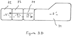
- the 3d figure represents another embodiment of the invention in which the complementary modules 3, 3', 3" are arranged to respectively project beams 74, 73, and 72 successively from a side face of the main dipped beam 71 at cut-off at 15°
- the harnesses of the complementary modules 3, 3', 3" thus complete the main harness.
- Such an embodiment is particularly interesting in that it can be advantageously implemented in relation to the turning radius (or angle at the steering wheel) of the vehicle to provide additional illumination of the main beam 71 in bends so keep on going.
- the solid line arrow illustrates the case where the driver begins a bend whose curvature first requires a small angle at the steering wheel then an increasingly large angle, successively switching on continuously (so as not to create a "hole” in the global beam), the first complementary module 3, emitting the beam 74, the second complementary module 3', emitting the beam 73, then finally, the third complementary module 3", emitting the beam 72.
- the intensity of the lighting of the complementary modules is controlled so that the first complementary module 3 lights up very quickly at maximum intensity at most a few hundred milliseconds to reach 100% of the flux then the second then the third.
- Such an embodiment makes it possible, at lower cost, to implement a lighting function designated by the English acronym “DBL: Dynamic Bending Light”.
- the invention also relates to a method for controlling the lighting of the complementary modules 3, 3' and 3′′ implemented by the control unit 5 to perform the “DBL” lighting function.
- the invention also relates to a method for controlling the lighting of the complementary modules 3, 3' and 3" implemented by the control unit 5, to perform the lighting function in tight bends or at designated intersections also by the Anglo-Saxon expression "Cornering Light” mainly used in urban areas and at low speeds.
- This additional lighting function illuminates the inside of the bend as long as the vehicle speed is below 40 km/h (urban driving, winding road, intersection, parking manoeuvre, etc.). This function is triggered following activation of the corresponding direction indicator or from a certain angle of rotation of the steering wheel.
- This function is usually performed by the fog lamp corresponding to the direction of the turn and which comes on or goes off according to the angle of rotation of the steering wheel.
- Such a function is designated “static” in that the fog lamp is static, not mobile in rotation (azimuth).
Landscapes
- Engineering & Computer Science (AREA)
- Mechanical Engineering (AREA)
- Lighting Device Outwards From Vehicle And Optical Signal (AREA)
Description
- La présente invention concerne de manière générale un projecteur destiné à être monté sur un véhicule automobile.
- Il est connu dans l'art antérieur des dispositifs d'éclairage de route montés sur un véhicule automobile. Ces dispositifs font généralement partie d'un projecteur ou phare situé à l'avant du véhicule et projetant un faisceau lumineux vers l'avant du véhicule pour éclairer la route. De manière générale ces dispositifs comprennent un module d'éclairage incluant une source de lumière, un réflecteur, une carte de circuit imprimé dans le cas d'une diode électroluminescente comme source lumineuse, potentiellement une lentille pour projeter la lumière émise vers l'avant et une glace située devant pour protéger le dispositif. Un problème de ces dispositifs est qu'ils sont trop rigides en termes de modularité. En effet, un module d'éclairage émet un seul type de faisceau de sorte que la photométrie du projecteur, c'est-à-dire la zone illuminée devant le véhicule, est statique quelle que soit la condition de circulation à moins d'utiliser un élément tel qu'un masque, un écran ou encore un barillet ce qui rend le système et sa fabrication plus compliquée.
- Afin de remédier à ce type d'inconvénient, il a été trouvé d'utiliser plusieurs modules dans un même projecteur, chacun de ces modules émettant un faisceau particulier pour plus de modularité par exemple en modifiant leur forme, via un masque, ou encore leur intensité comme décrit dans
US 2001/0028565 . En revanche, un problème de ce type de dispositif est qu'il permet une certaine modularité d'éclairage mais au prix d'une performance issue d'un compromis optique des projecteurs du fait du nombre de fonctionnalités/distributions photométriques à réaliser. Des phases transitoires entre les différentes distributions photométriques provoquent également des gênes sur la route lors d'un passage d'un état à l'autre. - On connait également du
JP2005088856A - On connaît enfin du document
US 2009/0086500 A1 un projecteur comprenant un module principal pour feu de code et deux modules complémentaires orientables en azimut. Les deux modules complémentaires réalisent ensemble un faisceau complémentaire variable destiné à compléter le faisceau principal pour réaliser selon les besoins un faisceau de route adaptatif, un faisceau de virage et un faisceau pour autoroute. La position en site des faisceaux de chacun des modules complémentaires est modifiable par déplacement relatif de la source lumineuse et d'une optique à l'intérieur du module. - Un but de la présente invention est de répondre aux inconvénients des documents de l'art antérieurs mentionnés ci-dessus et en particulier, tout d'abord, de fournir un projecteur de véhicule économique, simple à mettre en œuvre et capable de fournir une photométrie modulable et combinant de multiples fonctionnalités à des niveaux de performances optimales.
- Pour cela un premier aspect de l'invention concerne un projecteur caractérisé par la partie caractérisante de la revendication 1
- Selon une caractéristique, l'unité de commande est apte à commander l'intensité de l'éclairage des modules complémentaires pour que le premier module complémentaire s'allume instantanément à intensité maximale puis le deuxième puis le troisième de manière à offrir un champ de vision nocturne maximal au conducteur du véhicule pendant le virage.
- Selon une autre caractéristique, l'unité de commande les modules en partant du module le plus intérieur au virage vers le module principal, pour qu'ils s'éteignent progressivement jusqu' à la sortie du virage.
- Un deuxième aspect de l'invention concerne un procédé de commande de l'éclairage des modules complémentaires d'un projecteur tel que décrit ci-dessus, caractérisé en ce qu'il consiste :
- à projeter respectivement et successivement les faisceaux des modules complémentaires à partir d'une face latérale du faisceau principal de croisement en fonction de l'angle de rotation du volant du véhicule pour réaliser un complément d'éclairage continu du faisceau principal à l'abord d'un virage ;
- à commander l'intensité de l'éclairage des modules complémentaires pour que le premier module complémentaire s'allume instantanément à intensité maximale puis le deuxième puis le troisième de manière à offrir un champ de vision nocturne maximal au conducteur du véhicule pendant le virage ;
- à éteindre progressivement les modules complémentaires en partant du module complémentaire le plus intérieur au virage vers le module d'éclairage principal jusqu' à la sortie du virage.
- Un troisième aspect de l'invention concerne un procédé de commande de l'éclairage des modules complémentaires d'un projecteur tel que décrit ci-dessus, caractérisé en ce qu'il consiste, lorsque que le véhicule est à une vitesse inférieure à une vitesse déterminée :
- à projeter simultanément les faisceaux des modules complémentaires dès qu'un angle déterminé de rotation du volant du véhicule est détecté et/ou l'activation de l'indicateur de direction pour réaliser une fonction d'éclairage d'intersection, en complément de l'éclairage du faisceau principal ;
- à éteindre progressivement les modules en partant du module le plus intérieur au virage vers le module d'éclairage principal à mesure que l'angle de rotation du volant se rapproche d'un angle nul.
- Selon une caractéristique du procédé décrit ci-dessus, tous les modules complémentaires sont allumés simultanément à puissance maximale dès qu'un angle de rotation du volant est détecté et/ou l'activation de l'indicateur de direction.
- Un quatrième aspect de l'invention concerne un véhicule automobile comportant au moins un projecteur de véhicule tel que décrit ci-dessus.
- D'autres caractéristiques et avantages de la présente invention apparaîtront plus clairement à la lecture de la description détaillée qui suit d'un mode de réalisation de l'invention donné à titre d'exemple nullement limitatif et illustré par les dessins annexés, dans lesquels :
- la
figure 1 représente un projecteur selon un mode de réalisation de la présente invention. - les
figures 2A et 2B représentent un premier mode de réalisation de photométrie du projecteur de la présente invention, - les
figures 3A à 3D représentent quatre autres modes de réalisation de photométrie du projecteur de la présente invention, - La
figure 1 représente un projecteur de véhicule 1 selon un mode de réalisation de la présente invention. - Comme représenté, ce projecteur comprend un module principal 2 , 2', 2" agencé pour émettre un faisceau de lumière principal 31, 41, 45, 51, 61, 71 de préférence un feu de route 2"/croisement 2, 2', c'est à dire qu'il est un module bi-fonction pouvant émettre un faisceau de feu de croisement ou un faisceau de feu de route, qui comprend un ou plusieurs moteurs (non visible) agencé pour le régler en site et en azimut selon les flèches verticale et horizontale de la
figure 1 . Bien que cela ne soit pas visible sur lafigure 1 , le faisceau principal de croisement peut être à coupure plate, c'est à dire que sa photométrie (zone d'illumination) est essentiellement rectangulaire sans zone d'illumination agrandie pour le bas côté de la route ou à coupure à X° (par exemple 15°) pour que le faisceau principal illumine également le bas côté de la route. - Egalement, ce projecteur comprend une pluralité de modules complémentaires 3, 3', 3" agencés pour émettre chacun un faisceau de lumière complémentaire 34, 44, 54, 74 ; 33, 43, 53, 73 ; 32, 42, 52, 62, 72, différent du faisceau de lumière principal 41, 45, 51, 61, 71. Par différent du faisceau principal, il est entendu la forme du faisceau, son intensité ou du même genre. Les modules complémentaires 3, 3', 3" comprennent de préférence chacun un moteur agencé pour régler le module complémentaire auquel il est destiné en site et en azimut indépendamment les uns des autres comme représenté par les flèches verticales et horizontales.
- En effet, le projecteur 1 comprend également un moyen de réglage 4, lequel peut inclure les moteurs précédemment évoqués, pour régler en site et en azimut chacun des modules d'éclairage 2, 2', 2", 3, 3', 3", principal et complémentaires, et une unité de commande 5 pour émettre un ordre aux moyens de réglages 4 pour orienter chacun des modules d'éclairage 2, 2', 2", 3, 3', 3" en site et en azimut indépendamment les uns des autres et commander l'intensité lumineuse de chaque module également indépendamment les uns des autres .
- Les
figures 2A et 2B représentent un mode de réalisation particulier de la présente invention dans lequel le module d'éclairage principal 2 est agencé pour émettre un faisceau de lumière 31 à coupure plate pour émettre un faisceau de feu de croisement (ou code) ». Ainsi le faisceau du module principal n'éclaire pas une zone supplémentaire du bas côté de la route plus en avant pas rapport au reste de la route. Cependant, au moins un 3 des trois modules complémentaires 3, 3', 3" est agencé pour projeter un faisceau de coupure symétrique 34 adjacent à un côté avant du faisceau de lumière à coupure plate 31 de manière à venir en complément du faisceau de lumière à coupure plate 31 pour éclairer cette zone supplémentaire du bas côté de la route. De plus, dans la mesure où le module complémentaire 3est orientable en azimut, le moyen de réglage 4 peut déplacer horizontalement le faisceau de coupure symétrique 34 entre les extrémités latérales du faisceau de lumière à coupure plate 31 éclairer, au choix un bas côté à gauche ou à droite du véhicule mettant ainsi en œuvre une gestion DàD/DàG (direction à droite/direction à gauche). - En complément, comme représenté sur les
figures 2A et 2B les autres modules complémentaires 3' et 3" sont agencés pour projeter respectivement des faisceaux 33, 32 adjacents aux faces latérales du faisceau principal 31. Dans le cas de lafigure 2A et de lafigure 2B , le faisceau 32, a une forme rectangulaire, ce qui permet d'au moins partiellement le superposer avec le faisceau principal 2 et le faisceau à coupure symétrique 34 de manière à uniformiser le feu de croisement et est donc déplacé de préférence ensemble avec le faisceau de coupure 34. - On entend par adjacent la position des faisceaux complémentaires à la suite des faisceaux principaux. Cependant une légère superposition des faisceaux permettra de traiter l'homogénéité liée à l'association de ces différents faisceaux.
- Un tel mode de réalisation permet d'assurer un complément d'éclairage à celui obtenu par le faisceau de croisement, avec prise en compte du sens de conduite (direction à droite DàD /direction à gauche DàG) sans avoir besoin de réglage mécanique.
- La
figure 3A représente un autre mode de réalisation de l'invention dans lequel les modules complémentaires 3, 3', 3" sont agencés pour projeter de manière séquentielle leur faisceau 44, 43, 42 de sorte à superposer les faisceaux complémentaires séquentiellement avec le faisceau principal 41 de feu de croisement à coupure à 15°, ainsi qu'un faisceau appelé également «Spot » 45 émis par le faisceau principal de route 2". - On utilise le terme « Spot » parce ce qu'il se rapproche par sa forme ovoïde d'un spot d'éclairage, dont le contour est représenté par une ligne fermée discontinue, Le spot forme le faisceau de feu de route 45 en coopération avec le faisceau principal 41.
- Un tel mode de réalisation permet d'obtenir un complément de la fonction feu de route.
- La
figure 3C représente un autre mode de réalisation de l'invention dans lequel au moins l'un 3" des modules complémentaires 3, 3', 3" est agencé de manière à pouvoir émettre un faisceau 62 pouvant se déplacer selon les flèches horizontales et verticales par rapport au faisceau principal 61. - Un tel mode de réalisation permet de suivre une cible identifiée, de préférence, par un détecteur d'obstacle ou du même genre, aptitude désignées également par les termes anglo-saxons « Marking Light ».
- La
figure 3B représente un autre mode de réalisation de l'invention dans lequel les modules complémentaires 3, 3', 3" sont agencés pour projeter respectivement des faisceaux 52, 53, 54 de sorte que par exemple, un premier module 3" puisse émettre un faisceau 52 adjacent à une première face latérale du faisceau principal 51 de croisement à coupure à 15°, et un deuxième module 3 puisse émettre un faisceau 54, adjacent à la deuxième face latérale du faisceau principal 51. Ainsi, les premier et deuxième modules complémentaires 3" et 3 sont agencés pour projeter chacun un faisceau 52 et 54, de part et d'autre du faisceau principal 51.Le troisième module 3' vient ensuite « compléter » le faisceau 54 émis par le deuxième module 3 en étant adjacent à la face extérieure du faisceau 54. - On pourra ajouter à cette combinaison une diminution de la puissance du faisceau principal 51 afin de limiter les éblouissements les conducteurs des véhicules venant de face par réflexion de lumière sur la chaussée, mais aussi l'éblouissement du conducteur provoqué par la rétrodiffusion de lumière par les gouttelettes.
- Un tel mode de réalisation permet d'assurer un complément d'éclairage offert par le faisceau de feu de croisement, à droite et à gauche, du faisceau de croisement, dans le cas d'un roulage dans des conditions météorologiques difficiles désignées également par l'expression anglo-saxonne « Adverse Weather ».
- La
figure 3D représente un autre mode de réalisation de l'invention dans lequel les modules complémentaires 3, 3', 3" sont agencés pour projeter respectivement des faisceaux 74, 73, et 72 successivement à partir d'une face latérale du faisceau principal 71 de croisement à coupure à 15°. Les faisceaux des modules complémentaires 3, 3', 3" viennent ainsi compléter le faisceau principal. - Un tel mode de réalisation est particulièrement intéressant en ce qu'il peut être avantageusement mis en œuvre en relation avec le rayon de braquage (ou angle au volant) du véhicule pour réaliser un complément d'éclairage du faisceau principal 71 dans les virages de manière continue.
- On décrit ci-après un exemple de mise en œuvre en partant d'une situation où le véhicule roule en ligne droite, situation dans laquelle aucun des trois modules complémentaires 3', 3", 3" ne sont activés et où seul le faisceau principal 71 de croisement à coupure à 15° éclaire la route.
- La flèche en trait plein illustre le cas où le conducteur attaque un virage dont la courbure nécessite d'abord un petit angle au volant puis un angle de plus en plus grand, allumant successivement en continu (pour ne pas créer de « trou » dans le faisceau global), le premier module complémentaire 3, émettant le faisceau 74, le deuxième module complémentaire 3', émettant le faisceau 73, puis enfin, le troisième module complémentaire 3 ", émettant le faisceau 72.
- L'intensité de l'éclairage des modules complémentaires est commandée pour que le premier module complémentaire 3 s'allume très rapidement à intensité maximale au maximum quelques centaines de millisecondes pour arriver à 100% du flux puis le deuxième puis le troisième. Ainsi, lorsque le conducteur attaque un virage et que la courbure du virage augmente, son champ de vision nocturne soit maximal pendant tout le virage.
- A l'inverse, comme représenté par la flèche en trait interrompu, dont la direction est à l'opposé de la flèche en trait plein, les modules en partant du module 3" le plus intérieur au virage vers le module principal 2, s'éteignent progressivement. Cette progressivité de l'extinction des modules 3", 3' puis 3 est importante pour limiter l'impact visuel du conducteur pour lequel une transition brutale de l'intensité lumineuse ou flux lumineux pourrait détourner involontairement son attention. Elle peut se faire pendant un temps d'une seconde à quelques secondes.
- On se référera au document
US2001/0028565 pour illustrer l'évolution de l'intensité lumineuse en fonction de l'angle de rotation du volant. - Un tel mode de réalisation permet à moindre coût d'implémenter une fonction d'éclairage désignée par l'acronyme anglo-saxon «DBL : Dynamic Bending Light ».
- L'invention a également pour objet un procédé de commande de l'éclairage des modules complémentaires 3, 3' et 3"mis en œuvre par l'unité de commande 5 pour réaliser la fonction d'éclairage « DBL ».
- A cet effet, le procédé consiste :
- à projeter respectivement les faisceaux 74, 73, et 72 successivement à partir d'une face latérale du faisceau principal 71 de croisement en fonction de l'angle de rotation du volant du véhicule 1 pour réaliser un complément d'éclairage continu du faisceau principal 71 à l'abord d'un virage ;
- à commander l'intensité de l'éclairage des modules complémentaires 3, 3', 3" pour que le premier module complémentaire 3 s'allume instantanément à intensité maximale puis le deuxième 3' puis le troisième 3" de manière à offrir un champ de vision nocturne maximal au conducteur du véhicule pendant tout le virage ;
- à éteindre progressivement les modules 3, 3', 3" en partant du module 3" le plus intérieur au virage vers le module principal 2, jusqu' à la sortie du virage.
- L'invention a également pour objet un procédé de commande de l'éclairage des modules complémentaires 3, 3' et 3"mis en œuvre par l'unité de commande 5, pour réaliser la fonction d'éclairage en virages serrés ou aux intersections désignée également par l'expression anglo-saxonne « Cornering Light » essentiellement utilisée en zone urbaine et à faible vitesse.
- Cette fonction complémentaire d'éclairage permet d'éclairer l'intérieur du virage tant que la vitesse du véhicule est inférieure à 40 Km/h (conduite urbaine, route sinueuse, intersection, manœuvre de parking, ...). Cette fonction se déclenche suite à l'activation de l'indicateur de direction correspondant ou à partir d'un certain angle de rotation du volant.
- Cette fonction est habituellement réalisée par le feu antibrouillard correspondant au sens du virage et qui s'allume ou s'éteint en fonction de l'angle de rotation du volant.
- Une telle fonction est désignée « statique » en ce que le feu antibrouillard est statique, non mobile en rotation (azimut).
- Grace aux modules complémentaires selon l'invention, réglables, notamment en azimut, il est donc possible d'effectuer du « Cornering Light » dynamique.
- A la différence de la fonction « DBL », dans le cas de la fonction « Cornering Light », tous les modules complémentaires sont allumés simultanément à puissance maximale dès qu'un angle de rotation du volant est détecté et/ou l'activation de l'indicateur de direction, puis ils s'éteignent progressivement à mesure que l'angle de rotation du volant se rapproche d'un angle nul.
Claims (7)
- Projecteur de véhicule (1) comprenant un module d'éclairage principal (2) agencé pour émettre un faisceau de lumière principal (71) correspondant à un feu de croisement, une pluralité de modules d'éclairage complémentaires (3, 3', 3") adjacents, agencés pour émettre chacun un faisceau de lumière complémentaire (74, 73, 72) différent dudit faisceau de lumière principal (71), un moyen de réglage (4) en site et en azimut de chacun desdits modules d'éclairage (2, 2', 2", 3, 3', 3"), et une unité de commande (5), caractérisé en ce le moyen de réglage permet de régler l'orientation en site et en azimut chacun desdits modules d'éclairage complémentaires indépendamment les uns des autres de manière à réaliser plusieurs fonctions photométriques distinctes, et en ce que les modules complémentaires (3, 3', 3") sont agencés et commandés par l'unité de commande (5) qui est apte à commander l'intensité d'éclairage et l'orientation de chacun des modules d'éclairage complémentaires pour projeter respectivement et successivement dans l'espace et dans le temps leurs faisceaux (74, 73, et 72) à partir d'une face latérale du faisceau principal (71) en fonction de l'angle de rotation du volant du véhicule (1) pour réaliser un complément d'éclairage continu du faisceau principal (71) au cours d'un virage.
- Projecteur selon la revendication précédente, caractérisé en ce que l'unité de commande (5) est apte à commander l'intensité de l'éclairage des modules complémentaires (3, 3', 3") pour que le premier module complémentaire (3) s'allume instantanément à intensité maximale puis le deuxième (3') puis le troisième (3") de manière à offrir un champ de vision nocturne maximal au conducteur du véhicule pendant le virage.
- Projecteur selon la revendication précédente, caractérisé en ce que l'unité de commande (5) commande les modules en partant du module (3") le plus intérieur au virage vers le module principal (2), pour qu'ils s'éteignent progressivement jusqu' à la sortie du virage.
- Procédé de commande de l'éclairage des modules complémentaires (3, 3', 3") d'un projecteur selon l'une des revendications 2 et 3, caractérisé en ce qu'il consiste :- à projeter respectivement et successivement les faisceaux (74, 73, 72) des modules complémentaires (3, 3', 3") à partir d'une face latérale du faisceau principal (71) de croisement en fonction de l'angle de rotation du volant du véhicule (1) pour réaliser un complément d'éclairage continu du faisceau principal (71) à l'abord d'un virage ;- à commander l'intensité de l'éclairage des modules complémentaires (3, 3', 3") pour que le premier module complémentaire (3) s'allume instantanément à intensité maximale puis le deuxième (3') puis le troisième (3") de manière à offrir un champ de vision nocturne maximal au conducteur du véhicule (1) pendant le virage ;- à éteindre progressivement les modules complémentaires (3, 3', 3") en partant du module complémentaire (3") le plus intérieur au virage vers le module d'éclairage principal (2) jusqu' à la sortie du virage.
- Procédé de commande de l'éclairage des modules complémentaires (3, 3', 3") d'un projecteur selon la revendication 1, caractérisé en ce qu'il consiste, lorsque que le véhicule est à une vitesse inférieure à une vitesse déterminée :- à projeter simultanément les faisceaux (74, 73, 72) des modules complémentaires (3, 3', 3") dès qu'un angle déterminé de rotation du volant du véhicule (1) est détecté et/ou l'activation de l'indicateur de direction pour réaliser une fonction d'éclairage d'intersection, en complément de l'éclairage du faisceau principal (71) ;- à éteindre progressivement les modules (3, 3', 3") en partant du module (3") le plus intérieur au virage vers le module d'éclairage principal (2) à mesure que l'angle de rotation du volant se rapproche d'un angle nul.
- Procédé selon la revendication précédente, caractérisé en ce que tous les modules complémentaires sont allumés simultanément à puissance maximale dès qu'un angle de rotation du volant est détecté et/ou l'activation de l'indicateur de direction.
- Véhicule automobile (1) comportant au moins un projecteur de véhicule selon l'une des revendications 1 à 3.
Applications Claiming Priority (2)
| Application Number | Priority Date | Filing Date | Title |
|---|---|---|---|
| FR1652688A FR3049523B1 (fr) | 2016-03-29 | 2016-03-29 | Projecteur de vehicule |
| PCT/FR2017/050638 WO2017168072A1 (fr) | 2016-03-29 | 2017-03-20 | Projecteur de véhicule |
Publications (2)
| Publication Number | Publication Date |
|---|---|
| EP3436307A1 EP3436307A1 (fr) | 2019-02-06 |
| EP3436307B1 true EP3436307B1 (fr) | 2022-05-11 |
Family
ID=56372987
Family Applications (1)
| Application Number | Title | Priority Date | Filing Date |
|---|---|---|---|
| EP17716952.1A Active EP3436307B1 (fr) | 2016-03-29 | 2017-03-20 | Projecteur de véhicule |
Country Status (4)
| Country | Link |
|---|---|
| EP (1) | EP3436307B1 (fr) |
| CN (1) | CN109070790B (fr) |
| FR (1) | FR3049523B1 (fr) |
| WO (1) | WO2017168072A1 (fr) |
Family Cites Families (8)
| Publication number | Priority date | Publication date | Assignee | Title |
|---|---|---|---|---|
| JP2001270383A (ja) | 2000-03-28 | 2001-10-02 | Koito Mfg Co Ltd | 車両用前照灯システム |
| JP4168890B2 (ja) * | 2003-09-19 | 2008-10-22 | 市光工業株式会社 | 車両用灯具 |
| DE102004055882A1 (de) * | 2004-11-19 | 2006-06-01 | Audi Ag | Kraftfahrzeug mit einer Beleuchtungseinrichtung umfassend ein Steuergerät und ein über das Steuergerät zum Ausleuchten einer Kurve in Abhängigkeit des über einen Lenkwinkelsensor erfassten Lenkwinkels ansteuerbares Leuchtmittel |
| JP2008074327A (ja) * | 2006-09-25 | 2008-04-03 | Mazda Motor Corp | 車両用照明装置 |
| DE102007038563A1 (de) * | 2007-08-16 | 2009-02-19 | Daimler Ag | Beleuchtungssystem für ein Kraftfahrzeug |
| JP4997052B2 (ja) * | 2007-10-01 | 2012-08-08 | 株式会社小糸製作所 | 車両用前照灯 |
| FR2955729B1 (fr) * | 2010-01-22 | 2012-12-14 | Valeo Vision | Procede de detection pour un vehicule automobile |
| CN102582508A (zh) * | 2012-03-19 | 2012-07-18 | 中国汽车技术研究中心 | 一种车辆夜间弯道辅助与视觉增强装置及其方法 |
-
2016
- 2016-03-29 FR FR1652688A patent/FR3049523B1/fr not_active Expired - Fee Related
-
2017
- 2017-03-20 EP EP17716952.1A patent/EP3436307B1/fr active Active
- 2017-03-20 CN CN201780020932.4A patent/CN109070790B/zh active Active
- 2017-03-20 WO PCT/FR2017/050638 patent/WO2017168072A1/fr not_active Ceased
Also Published As
| Publication number | Publication date |
|---|---|
| WO2017168072A1 (fr) | 2017-10-05 |
| FR3049523A1 (fr) | 2017-10-06 |
| CN109070790A (zh) | 2018-12-21 |
| CN109070790B (zh) | 2022-07-19 |
| EP3436307A1 (fr) | 2019-02-06 |
| FR3049523B1 (fr) | 2020-01-31 |
Similar Documents
| Publication | Publication Date | Title |
|---|---|---|
| EP3115256B1 (fr) | Procede de contrôle d'un faisceau lumineux et système d'eclairage correspondant | |
| EP2690352B1 (fr) | Système d'éclairage adaptatif pour véhicule automobile | |
| EP2957464B1 (fr) | Module d éclairage et/ou de signalisation rotatif | |
| EP2128521B1 (fr) | Projecteur de véhicule automobile susceptible d'émettre un faisceau lumineux orientable. | |
| EP1449716B1 (fr) | Dispositif d'éclairage pour un véhicule automobile | |
| FR2811276A1 (fr) | Systeme de phares pour vehicules et procede pour leur commande | |
| EP1748251B1 (fr) | Dispositif d'éclairage pour véhicule automobile | |
| EP2546569B1 (fr) | Dispositif d'éclairage / signalisation multifonctions pour véhicule automobile | |
| EP4281321B1 (fr) | Système d'éclairage de véhicule automobile muni d'un module lumineux apte à émettre un faisceau lumineux pixélisé | |
| EP2301801A1 (fr) | Procédé de commande d'un projecteur d'éclairage pour véhicule | |
| EP3224083A1 (fr) | Projecteur de véhicule | |
| EP2990264A2 (fr) | Procede de contrôle d'un faisceau lumineux et module d'eclairage et/ou de signalisation correspondant | |
| FR3021606A1 (fr) | Dispositif d'eclairage a lentille mobile pour vehicule automobile | |
| EP2957823B1 (fr) | Module d éclairage et/ou de signalisation rotatif | |
| EP1502814B2 (fr) | Projecteur code et virage pour véhicule automobile | |
| EP3453946A1 (fr) | Module lumineux pour véhicule automobile, et dispositif d'éclairage et/ou de signalisation muni d'un tel module | |
| EP3455102B1 (fr) | Systeme et procede d'eclairage pour vehicule automobile | |
| EP1366955B1 (fr) | Dispositif de sécurité anti-éblouissement pour projecteur de véhicule automobile | |
| EP1870283B1 (fr) | Ensemble projecteur à trois fonctions pour véhicule automobile | |
| EP2168812B1 (fr) | Système d'éclairage pour véhicule automobile apte à modifier l'émission d'un faisceau lumineux de type code | |
| EP3436307A1 (fr) | Projecteur de véhicule | |
| EP1619440A1 (fr) | Dispositif d'éclairage pour véhicule automobile avec superposition de faisceaux | |
| EP1762431A1 (fr) | Dispositif d'éclairage pour véhicule automobile | |
| FR2845330A1 (fr) | Dispositif d'eclairage et/ou de signalisation du type projecteur pour vehicule automobile | |
| EP1953039A2 (fr) | Dispositif d'éclairage multifonction pour véhicule automobile |
Legal Events
| Date | Code | Title | Description |
|---|---|---|---|
| STAA | Information on the status of an ep patent application or granted ep patent |
Free format text: STATUS: UNKNOWN |
|
| STAA | Information on the status of an ep patent application or granted ep patent |
Free format text: STATUS: THE INTERNATIONAL PUBLICATION HAS BEEN MADE |
|
| PUAI | Public reference made under article 153(3) epc to a published international application that has entered the european phase |
Free format text: ORIGINAL CODE: 0009012 |
|
| STAA | Information on the status of an ep patent application or granted ep patent |
Free format text: STATUS: REQUEST FOR EXAMINATION WAS MADE |
|
| 17P | Request for examination filed |
Effective date: 20181005 |
|
| AK | Designated contracting states |
Kind code of ref document: A1 Designated state(s): AL AT BE BG CH CY CZ DE DK EE ES FI FR GB GR HR HU IE IS IT LI LT LU LV MC MK MT NL NO PL PT RO RS SE SI SK SM TR |
|
| AX | Request for extension of the european patent |
Extension state: BA ME |
|
| DAV | Request for validation of the european patent (deleted) | ||
| DAX | Request for extension of the european patent (deleted) | ||
| RAP1 | Party data changed (applicant data changed or rights of an application transferred) |
Owner name: PSA AUTOMOBILES SA |
|
| GRAP | Despatch of communication of intention to grant a patent |
Free format text: ORIGINAL CODE: EPIDOSNIGR1 |
|
| STAA | Information on the status of an ep patent application or granted ep patent |
Free format text: STATUS: GRANT OF PATENT IS INTENDED |
|
| INTG | Intention to grant announced |
Effective date: 20220121 |
|
| GRAS | Grant fee paid |
Free format text: ORIGINAL CODE: EPIDOSNIGR3 |
|
| GRAA | (expected) grant |
Free format text: ORIGINAL CODE: 0009210 |
|
| STAA | Information on the status of an ep patent application or granted ep patent |
Free format text: STATUS: THE PATENT HAS BEEN GRANTED |
|
| AK | Designated contracting states |
Kind code of ref document: B1 Designated state(s): AL AT BE BG CH CY CZ DE DK EE ES FI FR GB GR HR HU IE IS IT LI LT LU LV MC MK MT NL NO PL PT RO RS SE SI SK SM TR |
|
| REG | Reference to a national code |
Ref country code: GB Ref legal event code: FG4D Free format text: NOT ENGLISH |
|
| REG | Reference to a national code |
Ref country code: DE Ref legal event code: R084 Ref document number: 602017057298 Country of ref document: DE Ref country code: CH Ref legal event code: EP |
|
| REG | Reference to a national code |
Ref country code: AT Ref legal event code: REF Ref document number: 1491147 Country of ref document: AT Kind code of ref document: T Effective date: 20220515 |
|
| REG | Reference to a national code |
Ref country code: DE Ref legal event code: R096 Ref document number: 602017057298 Country of ref document: DE |
|
| REG | Reference to a national code |
Ref country code: IE Ref legal event code: FG4D Free format text: LANGUAGE OF EP DOCUMENT: FRENCH |
|
| REG | Reference to a national code |
Ref country code: GB Ref legal event code: 746 Effective date: 20220531 |
|
| REG | Reference to a national code |
Ref country code: LT Ref legal event code: MG9D |
|
| REG | Reference to a national code |
Ref country code: NL Ref legal event code: MP Effective date: 20220511 |
|
| REG | Reference to a national code |
Ref country code: AT Ref legal event code: MK05 Ref document number: 1491147 Country of ref document: AT Kind code of ref document: T Effective date: 20220511 |
|
| PG25 | Lapsed in a contracting state [announced via postgrant information from national office to epo] |
Ref country code: SE Free format text: LAPSE BECAUSE OF FAILURE TO SUBMIT A TRANSLATION OF THE DESCRIPTION OR TO PAY THE FEE WITHIN THE PRESCRIBED TIME-LIMIT Effective date: 20220511 Ref country code: PT Free format text: LAPSE BECAUSE OF FAILURE TO SUBMIT A TRANSLATION OF THE DESCRIPTION OR TO PAY THE FEE WITHIN THE PRESCRIBED TIME-LIMIT Effective date: 20220912 Ref country code: NO Free format text: LAPSE BECAUSE OF FAILURE TO SUBMIT A TRANSLATION OF THE DESCRIPTION OR TO PAY THE FEE WITHIN THE PRESCRIBED TIME-LIMIT Effective date: 20220811 Ref country code: NL Free format text: LAPSE BECAUSE OF FAILURE TO SUBMIT A TRANSLATION OF THE DESCRIPTION OR TO PAY THE FEE WITHIN THE PRESCRIBED TIME-LIMIT Effective date: 20220511 Ref country code: LT Free format text: LAPSE BECAUSE OF FAILURE TO SUBMIT A TRANSLATION OF THE DESCRIPTION OR TO PAY THE FEE WITHIN THE PRESCRIBED TIME-LIMIT Effective date: 20220511 Ref country code: HR Free format text: LAPSE BECAUSE OF FAILURE TO SUBMIT A TRANSLATION OF THE DESCRIPTION OR TO PAY THE FEE WITHIN THE PRESCRIBED TIME-LIMIT Effective date: 20220511 Ref country code: GR Free format text: LAPSE BECAUSE OF FAILURE TO SUBMIT A TRANSLATION OF THE DESCRIPTION OR TO PAY THE FEE WITHIN THE PRESCRIBED TIME-LIMIT Effective date: 20220812 Ref country code: FI Free format text: LAPSE BECAUSE OF FAILURE TO SUBMIT A TRANSLATION OF THE DESCRIPTION OR TO PAY THE FEE WITHIN THE PRESCRIBED TIME-LIMIT Effective date: 20220511 Ref country code: ES Free format text: LAPSE BECAUSE OF FAILURE TO SUBMIT A TRANSLATION OF THE DESCRIPTION OR TO PAY THE FEE WITHIN THE PRESCRIBED TIME-LIMIT Effective date: 20220511 Ref country code: BG Free format text: LAPSE BECAUSE OF FAILURE TO SUBMIT A TRANSLATION OF THE DESCRIPTION OR TO PAY THE FEE WITHIN THE PRESCRIBED TIME-LIMIT Effective date: 20220811 Ref country code: AT Free format text: LAPSE BECAUSE OF FAILURE TO SUBMIT A TRANSLATION OF THE DESCRIPTION OR TO PAY THE FEE WITHIN THE PRESCRIBED TIME-LIMIT Effective date: 20220511 |
|
| PG25 | Lapsed in a contracting state [announced via postgrant information from national office to epo] |
Ref country code: RS Free format text: LAPSE BECAUSE OF FAILURE TO SUBMIT A TRANSLATION OF THE DESCRIPTION OR TO PAY THE FEE WITHIN THE PRESCRIBED TIME-LIMIT Effective date: 20220511 Ref country code: PL Free format text: LAPSE BECAUSE OF FAILURE TO SUBMIT A TRANSLATION OF THE DESCRIPTION OR TO PAY THE FEE WITHIN THE PRESCRIBED TIME-LIMIT Effective date: 20220511 Ref country code: LV Free format text: LAPSE BECAUSE OF FAILURE TO SUBMIT A TRANSLATION OF THE DESCRIPTION OR TO PAY THE FEE WITHIN THE PRESCRIBED TIME-LIMIT Effective date: 20220511 Ref country code: IS Free format text: LAPSE BECAUSE OF FAILURE TO SUBMIT A TRANSLATION OF THE DESCRIPTION OR TO PAY THE FEE WITHIN THE PRESCRIBED TIME-LIMIT Effective date: 20220911 |
|
| PG25 | Lapsed in a contracting state [announced via postgrant information from national office to epo] |
Ref country code: SM Free format text: LAPSE BECAUSE OF FAILURE TO SUBMIT A TRANSLATION OF THE DESCRIPTION OR TO PAY THE FEE WITHIN THE PRESCRIBED TIME-LIMIT Effective date: 20220511 Ref country code: SK Free format text: LAPSE BECAUSE OF FAILURE TO SUBMIT A TRANSLATION OF THE DESCRIPTION OR TO PAY THE FEE WITHIN THE PRESCRIBED TIME-LIMIT Effective date: 20220511 Ref country code: RO Free format text: LAPSE BECAUSE OF FAILURE TO SUBMIT A TRANSLATION OF THE DESCRIPTION OR TO PAY THE FEE WITHIN THE PRESCRIBED TIME-LIMIT Effective date: 20220511 Ref country code: EE Free format text: LAPSE BECAUSE OF FAILURE TO SUBMIT A TRANSLATION OF THE DESCRIPTION OR TO PAY THE FEE WITHIN THE PRESCRIBED TIME-LIMIT Effective date: 20220511 Ref country code: DK Free format text: LAPSE BECAUSE OF FAILURE TO SUBMIT A TRANSLATION OF THE DESCRIPTION OR TO PAY THE FEE WITHIN THE PRESCRIBED TIME-LIMIT Effective date: 20220511 Ref country code: CZ Free format text: LAPSE BECAUSE OF FAILURE TO SUBMIT A TRANSLATION OF THE DESCRIPTION OR TO PAY THE FEE WITHIN THE PRESCRIBED TIME-LIMIT Effective date: 20220511 |
|
| REG | Reference to a national code |
Ref country code: DE Ref legal event code: R097 Ref document number: 602017057298 Country of ref document: DE |
|
| PLBE | No opposition filed within time limit |
Free format text: ORIGINAL CODE: 0009261 |
|
| STAA | Information on the status of an ep patent application or granted ep patent |
Free format text: STATUS: NO OPPOSITION FILED WITHIN TIME LIMIT |
|
| PG25 | Lapsed in a contracting state [announced via postgrant information from national office to epo] |
Ref country code: AL Free format text: LAPSE BECAUSE OF FAILURE TO SUBMIT A TRANSLATION OF THE DESCRIPTION OR TO PAY THE FEE WITHIN THE PRESCRIBED TIME-LIMIT Effective date: 20220511 |
|
| 26N | No opposition filed |
Effective date: 20230214 |
|
| PG25 | Lapsed in a contracting state [announced via postgrant information from national office to epo] |
Ref country code: SI Free format text: LAPSE BECAUSE OF FAILURE TO SUBMIT A TRANSLATION OF THE DESCRIPTION OR TO PAY THE FEE WITHIN THE PRESCRIBED TIME-LIMIT Effective date: 20220511 |
|
| PG25 | Lapsed in a contracting state [announced via postgrant information from national office to epo] |
Ref country code: MC Free format text: LAPSE BECAUSE OF FAILURE TO SUBMIT A TRANSLATION OF THE DESCRIPTION OR TO PAY THE FEE WITHIN THE PRESCRIBED TIME-LIMIT Effective date: 20220511 |
|
| REG | Reference to a national code |
Ref country code: CH Ref legal event code: PL |
|
| REG | Reference to a national code |
Ref country code: BE Ref legal event code: MM Effective date: 20230331 |
|
| PG25 | Lapsed in a contracting state [announced via postgrant information from national office to epo] |
Ref country code: LU Free format text: LAPSE BECAUSE OF NON-PAYMENT OF DUE FEES Effective date: 20230320 |
|
| REG | Reference to a national code |
Ref country code: IE Ref legal event code: MM4A |
|
| PG25 | Lapsed in a contracting state [announced via postgrant information from national office to epo] |
Ref country code: LI Free format text: LAPSE BECAUSE OF NON-PAYMENT OF DUE FEES Effective date: 20230331 Ref country code: IT Free format text: LAPSE BECAUSE OF FAILURE TO SUBMIT A TRANSLATION OF THE DESCRIPTION OR TO PAY THE FEE WITHIN THE PRESCRIBED TIME-LIMIT Effective date: 20220511 Ref country code: IE Free format text: LAPSE BECAUSE OF NON-PAYMENT OF DUE FEES Effective date: 20230320 Ref country code: CH Free format text: LAPSE BECAUSE OF NON-PAYMENT OF DUE FEES Effective date: 20230331 |
|
| PG25 | Lapsed in a contracting state [announced via postgrant information from national office to epo] |
Ref country code: BE Free format text: LAPSE BECAUSE OF NON-PAYMENT OF DUE FEES Effective date: 20230331 |
|
| REG | Reference to a national code |
Ref country code: DE Ref legal event code: R081 Ref document number: 602017057298 Country of ref document: DE Owner name: STELLANTIS AUTO SAS, FR Free format text: FORMER OWNER: PSA AUTOMOBILES SA, POISSY, FR |
|
| PG25 | Lapsed in a contracting state [announced via postgrant information from national office to epo] |
Ref country code: BG Free format text: LAPSE BECAUSE OF FAILURE TO SUBMIT A TRANSLATION OF THE DESCRIPTION OR TO PAY THE FEE WITHIN THE PRESCRIBED TIME-LIMIT Effective date: 20220511 |
|
| PG25 | Lapsed in a contracting state [announced via postgrant information from national office to epo] |
Ref country code: BG Free format text: LAPSE BECAUSE OF FAILURE TO SUBMIT A TRANSLATION OF THE DESCRIPTION OR TO PAY THE FEE WITHIN THE PRESCRIBED TIME-LIMIT Effective date: 20220511 |
|
| PG25 | Lapsed in a contracting state [announced via postgrant information from national office to epo] |
Ref country code: CY Free format text: LAPSE BECAUSE OF FAILURE TO SUBMIT A TRANSLATION OF THE DESCRIPTION OR TO PAY THE FEE WITHIN THE PRESCRIBED TIME-LIMIT; INVALID AB INITIO Effective date: 20170320 |
|
| PG25 | Lapsed in a contracting state [announced via postgrant information from national office to epo] |
Ref country code: HU Free format text: LAPSE BECAUSE OF FAILURE TO SUBMIT A TRANSLATION OF THE DESCRIPTION OR TO PAY THE FEE WITHIN THE PRESCRIBED TIME-LIMIT; INVALID AB INITIO Effective date: 20170320 |
|
| PG25 | Lapsed in a contracting state [announced via postgrant information from national office to epo] |
Ref country code: TR Free format text: LAPSE BECAUSE OF FAILURE TO SUBMIT A TRANSLATION OF THE DESCRIPTION OR TO PAY THE FEE WITHIN THE PRESCRIBED TIME-LIMIT Effective date: 20220511 |
|
| PGFP | Annual fee paid to national office [announced via postgrant information from national office to epo] |
Ref country code: GB Payment date: 20260220 Year of fee payment: 10 |
|
| PGFP | Annual fee paid to national office [announced via postgrant information from national office to epo] |
Ref country code: DE Payment date: 20260219 Year of fee payment: 10 |
|
| PGFP | Annual fee paid to national office [announced via postgrant information from national office to epo] |
Ref country code: FR Payment date: 20260219 Year of fee payment: 10 |