EP3435497A1 - Montagehilfsmittel für ein herstellen einer schraubverbindung zwischen einem elektrischen stecker- oder buchsen-teil und einem anschlusskörper - Google Patents
Montagehilfsmittel für ein herstellen einer schraubverbindung zwischen einem elektrischen stecker- oder buchsen-teil und einem anschlusskörper Download PDFInfo
- Publication number
- EP3435497A1 EP3435497A1 EP18181875.8A EP18181875A EP3435497A1 EP 3435497 A1 EP3435497 A1 EP 3435497A1 EP 18181875 A EP18181875 A EP 18181875A EP 3435497 A1 EP3435497 A1 EP 3435497A1
- Authority
- EP
- European Patent Office
- Prior art keywords
- main axis
- along
- mounting aid
- aid according
- section
- Prior art date
- Legal status (The legal status is an assumption and is not a legal conclusion. Google has not performed a legal analysis and makes no representation as to the accuracy of the status listed.)
- Granted
Links
Images




Classifications
-
- H—ELECTRICITY
- H01—ELECTRIC ELEMENTS
- H01R—ELECTRICALLY-CONDUCTIVE CONNECTIONS; STRUCTURAL ASSOCIATIONS OF A PLURALITY OF MUTUALLY-INSULATED ELECTRICAL CONNECTING ELEMENTS; COUPLING DEVICES; CURRENT COLLECTORS
- H01R43/00—Apparatus or processes specially adapted for manufacturing, assembling, maintaining, or repairing of line connectors or current collectors or for joining electric conductors
-
- H—ELECTRICITY
- H01—ELECTRIC ELEMENTS
- H01R—ELECTRICALLY-CONDUCTIVE CONNECTIONS; STRUCTURAL ASSOCIATIONS OF A PLURALITY OF MUTUALLY-INSULATED ELECTRICAL CONNECTING ELEMENTS; COUPLING DEVICES; CURRENT COLLECTORS
- H01R43/00—Apparatus or processes specially adapted for manufacturing, assembling, maintaining, or repairing of line connectors or current collectors or for joining electric conductors
- H01R43/005—Apparatus or processes specially adapted for manufacturing, assembling, maintaining, or repairing of line connectors or current collectors or for joining electric conductors for making dustproof, splashproof, drip-proof, waterproof, or flameproof connection, coupling, or casing
-
- B—PERFORMING OPERATIONS; TRANSPORTING
- B25—HAND TOOLS; PORTABLE POWER-DRIVEN TOOLS; MANIPULATORS
- B25B—TOOLS OR BENCH DEVICES NOT OTHERWISE PROVIDED FOR, FOR FASTENING, CONNECTING, DISENGAGING, OR HOLDING
- B25B13/00—Spanners; Wrenches
- B25B13/02—Spanners; Wrenches with rigid jaws
- B25B13/06—Spanners; Wrenches with rigid jaws of socket type
- B25B13/065—Spanners; Wrenches with rigid jaws of socket type characterised by the cross-section of the socket
-
- B—PERFORMING OPERATIONS; TRANSPORTING
- B25—HAND TOOLS; PORTABLE POWER-DRIVEN TOOLS; MANIPULATORS
- B25B—TOOLS OR BENCH DEVICES NOT OTHERWISE PROVIDED FOR, FOR FASTENING, CONNECTING, DISENGAGING, OR HOLDING
- B25B15/00—Screwdrivers
- B25B15/001—Screwdrivers characterised by material or shape of the tool bit
- B25B15/004—Screwdrivers characterised by material or shape of the tool bit characterised by cross-section
-
- H—ELECTRICITY
- H01—ELECTRIC ELEMENTS
- H01R—ELECTRICALLY-CONDUCTIVE CONNECTIONS; STRUCTURAL ASSOCIATIONS OF A PLURALITY OF MUTUALLY-INSULATED ELECTRICAL CONNECTING ELEMENTS; COUPLING DEVICES; CURRENT COLLECTORS
- H01R13/00—Details of coupling devices of the kinds covered by groups H01R12/70 or H01R24/00 - H01R33/00
- H01R13/73—Means for mounting coupling parts to apparatus or structures, e.g. to a wall
- H01R13/74—Means for mounting coupling parts in openings of a panel
- H01R13/746—Means for mounting coupling parts in openings of a panel using a screw ring
-
- H—ELECTRICITY
- H01—ELECTRIC ELEMENTS
- H01R—ELECTRICALLY-CONDUCTIVE CONNECTIONS; STRUCTURAL ASSOCIATIONS OF A PLURALITY OF MUTUALLY-INSULATED ELECTRICAL CONNECTING ELEMENTS; COUPLING DEVICES; CURRENT COLLECTORS
- H01R43/00—Apparatus or processes specially adapted for manufacturing, assembling, maintaining, or repairing of line connectors or current collectors or for joining electric conductors
- H01R43/20—Apparatus or processes specially adapted for manufacturing, assembling, maintaining, or repairing of line connectors or current collectors or for joining electric conductors for assembling or disassembling contact members with insulating base, case or sleeve
- H01R43/22—Hand tools
-
- H—ELECTRICITY
- H01—ELECTRIC ELEMENTS
- H01R—ELECTRICALLY-CONDUCTIVE CONNECTIONS; STRUCTURAL ASSOCIATIONS OF A PLURALITY OF MUTUALLY-INSULATED ELECTRICAL CONNECTING ELEMENTS; COUPLING DEVICES; CURRENT COLLECTORS
- H01R13/00—Details of coupling devices of the kinds covered by groups H01R12/70 or H01R24/00 - H01R33/00
- H01R13/46—Bases; Cases
- H01R13/52—Dustproof, splashproof, drip-proof, waterproof, or flameproof cases
-
- H—ELECTRICITY
- H01—ELECTRIC ELEMENTS
- H01R—ELECTRICALLY-CONDUCTIVE CONNECTIONS; STRUCTURAL ASSOCIATIONS OF A PLURALITY OF MUTUALLY-INSULATED ELECTRICAL CONNECTING ELEMENTS; COUPLING DEVICES; CURRENT COLLECTORS
- H01R13/00—Details of coupling devices of the kinds covered by groups H01R12/70 or H01R24/00 - H01R33/00
- H01R13/73—Means for mounting coupling parts to apparatus or structures, e.g. to a wall
- H01R13/74—Means for mounting coupling parts in openings of a panel
-
- H—ELECTRICITY
- H01—ELECTRIC ELEMENTS
- H01R—ELECTRICALLY-CONDUCTIVE CONNECTIONS; STRUCTURAL ASSOCIATIONS OF A PLURALITY OF MUTUALLY-INSULATED ELECTRICAL CONNECTING ELEMENTS; COUPLING DEVICES; CURRENT COLLECTORS
- H01R43/00—Apparatus or processes specially adapted for manufacturing, assembling, maintaining, or repairing of line connectors or current collectors or for joining electric conductors
- H01R43/26—Apparatus or processes specially adapted for manufacturing, assembling, maintaining, or repairing of line connectors or current collectors or for joining electric conductors for engaging or disengaging the two parts of a coupling device
Definitions
- the invention relates to an assembly aid for producing a screw connection between an electrical plug or socket part and a connection body.
- Electric lights which are intended for outdoor use, usually have a housing which should be designed in a suitable manner close to the outside space, so that when operating the lamp no moisture, dust u. s. w. undesirably enters the interior of the housing.
- IP IP: ingress protection
- FIG. 12a and 12b two perspective sketches of such a contact arrangement with a corresponding male part 11 are shown and in the Figures 13a and 13b two perspective sketches of a further contact arrangement with a, corresponding to the male part 11 corresponding female part 11 '.
- the plug part 11 has contact pins 13 for the power line.
- the - in this example, five - pins 13 are separated from each other by a, consisting of an electrically insulating material separating portion 14 which forms a cylindrical receptacle 13 for each of the contact pins.
- the plug part 11 can be used to form the contact arrangement - in the sense of a modular system - with a connection body 20 via a screw connection be connected, wherein the connecting body 20 serves as a carrier for the connector part 11.
- Fig. 3 a cutaway perspective sketch of the connector body 20 and the connector part 11 is shown.
- the plug part 11 has an external thread 12
- the connection body 20 has an internal thread 23 which accordingly meshes or cooperates with the external thread 12 of the plug part 11.
- connection body 20 has a flange 21 at a first end region and an external thread 22 at a second end region.
- the flange 21 has a larger diameter than the relevant through hole of a corresponding housing wall 30.
- the external thread 22 of the connection body 20 has a smaller diameter than that through hole.
- the union nut 26 can be tightened with a torque wrench with a torque provided. In this way, the tightness between the connector body 20 and the housing wall 30 can be suitably achieved.
- the plug part 11 is further designed so that in principle the screw connection between the plug part 11 and the connection body 20 can be suitably achieved tight.
- the plug part 11 is usually screwed by hand into the connecting body 20, so that the probability is relatively high that in this case a correspondingly suitable Torque is not effected and as a result, the desired tightness between the male part 11 on the one hand and the connector body 20 on the other hand is not achieved.
- the socket part 11 has hollow-cylindrical receiving areas 13' which serve to receive the contact pins 13, so that the desired electrical connection can be produced in this way.
- the invention has for its object to provide a mounting tool, with which the production of a screw connection between an electrical plug or socket part and a connector body is better possible.
- an assembly aid for making a threaded connection between an electrical male or female part and a terminal body having a first portion extending along a major axis of the mounting tool and a first portion along the major axis subsequent second section which - with respect to a rotational movement about the main axis - rotatably connected to the first section.
- the first section has an engagement surface for a torque wrench for rotation about the main axis.
- the second section has at least two receiving areas for the positive reception of a respective contact element (in particular of the aforementioned electrical plug or socket part), wherein the receiving areas each by a Wall area are formed, which extends around an axis oriented parallel to the main axis, wherein the axes do not coincide.
- a specific torque which is transmitted to the assembly aid with the aid of the torque wrench, can be transmitted in a suitable manner to the plug or socket part.
- the above-mentioned screw connection between the male or female part on the one hand and a corresponding connector body on the other hand can be more accurately determined quantitatively. This is particularly advantageous because in this way a certain desired tightness of the screw can be effected particularly suitable.
- the wall regions each describe a cylindrical surface. This is advantageous with respect to the production of the mounting aid and also with respect to a suitable positive contact of the receiving areas with contact elements.
- the second section preferably has at least two hollow-cylinder-shaped partial regions, the wall regions each being part of one of the hollow-cylinder-shaped partial regions.
- the receiving areas can be particularly suitable form through the hollow cylinder-shaped portions of the second portion.
- the assembly aid is particularly suitable for attack on a corresponding connector part.
- the receiving areas have an extent along the major axis that is between 20% and 80%, preferably between 30% and 70%, of the extension of the mounting tool along the major axis. This is advantageous with respect to a suitable torque transmission from the receiving areas to the contact elements upon rotation of the mounting aid about the main axis.
- the receiving areas are designed consistently in their forms. This is particularly advantageous in terms of manufacturing technology, and advantageous with respect to the torque transmission from the mounting tool to the male or female part.
- the receiving areas are arranged around the main axis, in particular distributed uniformly around the main axis. This too is advantageous with respect to a suitable torque transmission.
- the engagement surface of the first portion along the major axis has an extension which is between 20% and 80%, preferably between 30% and 70% of the extension of the mounting tool along the major axis.
- an extension which is between 20% and 80%, preferably between 30% and 70% of the extension of the mounting tool along the major axis.
- the first portion and the second portion are formed in one piece. In this way, a particularly direct-acting torque transmission from the engagement surface of the mounting tool on the male or female part is possible.
- the mounting tool is made up of one piece. This is particularly advantageous with respect to the manufacturing possibility.
- the mounting aid is preferably made of metal, in particular of steel. This is particularly advantageous with respect to torque transmission.
- the attack surface is formed by a hexagon or a square. This makes the assembly aid suitable for many common torque wrenches.
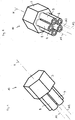
- FIGS 1 and 2 show perspective views of a first embodiment of an application according to the invention mounting aid 10.
- Das Mounting tool 10 is suitable for producing a screw connection between an electrical connector part and a connector body.
- the electrical connector part and the connection body can in particular - as shown in the figures - be designed according to the description above.
- the connector part so it can be in the Figures 12a, 12b and 3 shown connector part 11 act and in the connector body to the connector body 20th
- Fig. 3 shows a sectional perspective view of a relative arrangement between the mounting tool 10 and the male part 11 in a use of the mounting tool 10 for producing the screw connection between the male part 11 and the connector body 20th
- the assembly aid 10 has a, along a major axis H of the mounting tool 10 extending first portion 1, and one, along the main axis H to the first section 1 subsequent, in particular immediately adjacent second section 2. It is - with respect to a Rotary movement about the main axis H - the second section 2 rotatably connected to the first section 1.
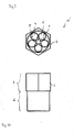
- Fig. 4 shows a sketch of the mounting tool 10 when looking at the second section 2 along the main axis H.
- Fig. 5 shows a sketch of the mounting tool 10 in a viewing direction perpendicular to the main axis H.
- first section 1 and the second section 2 may be formed in one piece.
- the two said sections 1, 2 may be integrally formed with each other.
- the assembly aid 10 is preferably formed from one piece.
- the assembly aid 10 may consist of a metal, for example of steel.
- the first section 1 has a torque wrench engagement face 3 for rotation about the major axis H.
- the attack surface 3 - as in the in the FIGS. 1 to 5 shown embodiment of the case - be formed by a hexagon; Alternatively, it may be formed for example by a square.
- the engagement surface 3 can, as shown, be an outwardly facing surface with respect to the main axis H, so that a torque wrench with a corresponding corresponding inwardly facing surface is suitable.
- the outer surface 3 a with respect to the Main axis H be inwardly facing surface, so that a torque wrench with a corresponding outer surface is suitable.
- the second section 2 has at least two receiving areas 4, 6 for the positive reception of a respective contact element, wherein the receiving areas 4, 6 - as exemplarily in Fig. 8 or Fig. 9 - are each formed by a wall portion 5, 7, which extends around an axis parallel to the main axis H oriented axis A1, A2.
- the design is such that the axes A1, A2 do not coincide.
- the design is also such that none of the axes A1, A2 coincides with the main axis H.
- the number of receiving areas 4, 6 may be, for example, between two and ten, preferably between three and eight. How out Fig. 2 shows, in total, for example, five receiving areas 4, 6 may be provided. In Fig. 2 is in addition to the two designated axes A1, A2 another axis designated by A3 as an example.
- the design is in particular such that the form fit when receiving the contact elements or contact pins 13 in the receiving areas 4, 6 is given with respect to a rotation about the main axis H.
- the procedure is as follows: First, the external thread 12 of the plug part 11 is brought into engagement, for example by hand, with the internal thread 23 of the connection body 20. Then, the mounting tool 10 is attached to the male part 11, so that the contact pins 13 of the male part 11 are received in the receiving areas 4, 6 of the mounting tool 10. Subsequently, the torque wrench is attached to the engagement surface 3 and transmitted by a rotation about the major axis H a desired torque from the mounting tool 10 on the male part 11. In this way, the screw connection between the plug part 11 and the connection body 20 can be produced particularly suitably with a certain desired torque. This is particularly advantageous with respect to a desired tightness between the male part 11 and the connector body 20th
- the design is such that the positive reception of the contact elements or the contact pins 13 in the receiving areas 4, 6 can be produced in the form of a translational movement parallel to the main axis H by a relative movement between the plug part 11 and the mounting aid 20.
- the assembly aid 20 can be attached to the contact pins 13 by a movement along the main axis H.
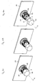
- FIGS. 6a to 6c this translational movement is illustrated.
- Fig. 6a recognizes the connector body 20, which is already connected as intended with a corresponding wall portion 30.
- the male part 11 is screwed into the connector body 20 a distance, so that the external thread 12 of the male part 11 is in engagement with the internal thread 23 of the connector body 20.
- the contact pins 13 of the plug part 11 can be seen.
- the assembly aid 10 is already aligned with its main axis H parallel to the contact pins 13, in such a way that the axes A1, A2 of the receiving areas 4, 6 coincide with the corresponding axes of the contact pins 13. Now - as in Fig.
- FIG. 6c shows the state in which the mounting tool 10 is completely attached to the male part 11.
- the, along the main axis H considered distance between the first portion 1 of the mounting tool 10, in particular the attack surface 3 on the one hand and the male part 11 on the other hand minimal. This is advantageous with respect to the following rotational movement of the first portion 1 about the major axis H and the torque transfer thereby effected to the male part 11.
- this is the design of the mounting tool 10 such that - viewed along the main axis H - the distance between the receiving areas 4, 6 and the attack surface 3 is very small, for example, less than 2 mm.
- the receiving areas 4, 6 can extend as far as the engagement surface 3, so that the distance in question is practically 0 mm.
- the wall regions 5, 7 are preferably each formed by a cylindrical surface 5, 7, in particular by a circular cylindrical surface.
- the receiving areas 4, 6 are particularly suitable when the contact pins 13 have a correspondingly corresponding circular cylindrical outer surface.
- the design of the second portion 2 may be such that it corresponds in shape to a front portion of a socket, which is provided for electrical connection to the male part 11, so for example in the Figures 13a and 13b shown bushing part 11 '. Accordingly, the second section 2 can be slid onto the plug part 11 like a socket corresponding to the plug part 11, so that the contact pins 13 of the plug part 11 are received in the receiving areas 4, 6 in a form-fitting manner.
- the second section 2 has at least two hollow-cylinder-shaped subregions 8, 9, wherein the wall regions 5, 7 are each part of one of the hollow cylinder-shaped subregions 8, 9.
- the inwardly facing surfaces of the corresponding hollow cylinder can be formed by the wall regions 5, 7.
- the hollow cylinder-shaped portions 8, 9 can accordingly match in shape and in their mutual arrangement with the aforementioned hollow-cylindrical receiving portions 13 'of the female part 11'.
- the receiving areas 4, 6 are preferably designed consistent in their forms.
- the receiving areas 4, 6 arranged around the main axis H around in particular distributed uniformly around the main axis H around, as exemplified in Fig. 4 shown.
- the design can in particular be such that - viewed in a cross section normal to the main axis H - the receiving areas 4, 6 lie on a circular line.
- the receiving areas 4 preferably have a - in Fig. 3 - extension ⁇ 1 along the major axis H, which is between 20% and 80%, preferably between 30% and 70% of the extension L of the assembly tool 10 along the major axis H.
- the extent ⁇ 1 can be between 40% and 60% of the extension L of the mounting aid 10 along the main axis H.
- the engagement surface 3 of the first portion 1 along the major axis H has an extension ⁇ 2, which is between 20% and 80%, preferably between 30% and 70% of the extension L of the mounting tool 10 along the main axis H.
- the extent ⁇ 2 between 40% and 60% of the extension L of the mounting tool 10 along the main axis H amount. This is advantageous with respect to a suitable torque transmission from the mounting tool 10 to the male part 11 for a given size of the mounting tool 10th
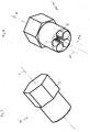
- FIGS. 7 to 10 is a second embodiment of a fitting according to the application - shown here - with the reference numeral 10 '- shown.
- the FIGS. 7 and 8 show the mounting tool 10 'in perspective from two different directions of view.
- Fig. 9 shows a sketch of the mounting tool 10 'looking at the second section 2 along the main axis H.
- Fig. 10 shows a sketch of the mounting tool 10 'in a viewing direction perpendicular to the main axis H.
- the mounting aid 10 ' is suitable for producing a screw connection between an electrical socket part and a connection body.
- the electrical socket part and the connection body in particular - as shown in the figures - be designed according to the description above.
- the female part it may be so in the FIGS. 13a, 13b and 3 shown bushing part 11 'act and in the connector body to the corresponding connector body 20'.
- Fig. 3 shows a relative arrangement between the mounting tool 10 'and the female part 11' when using the mounting tool 10 'for making the screw connection between the female part 11' and the connector body 20 '.
- the mounting tool 10 'differs from the mounting tool 10 described above only in the shape of the second portion 2 for example Fig. 8
- the receiving areas 4, 6 designed larger, so that they can each receive a correspondingly larger contact element, in particular in the form of the aforementioned hollow-cylindrical receiving areas 13 'of the female part 11'.
- the - in Fig. 9 Wall sections 5, 7 a cylindrical surface whose diameter - compared to the first embodiment - is greater.
- the design may further be such that the receiving areas 4, 6 are not completely separated from each other, but are connected to each other in an area around the main axis H or merge into each other.
- the second section 2 may be configured in its shape with the aforementioned separation region 14 of the plug part 11 coincident.
- FIGS. 11a to 11c show - in an analogous manner to the representation of FIGS. 6a to 6c -
- an electrical plug part 11 or socket part 11 ' can be screwed with a specific desired torque with a corresponding connection element 20 or 20'.
- a desired tightness between the two screwed parts can be achieved in a particularly suitable manner.
- the screw connection can also be made in a state in which the male part or female part already as intended connected to the housing wall of the lamp. This is basically possible even if the luminaire is already installed for operation. It can therefore be avoided in particular that the luminaire housing must be opened or the entire lamp must first be removed from the operating site.
Landscapes
- Engineering & Computer Science (AREA)
- Manufacturing & Machinery (AREA)
- Mechanical Engineering (AREA)
- Connector Housings Or Holding Contact Members (AREA)
- Details Of Spanners, Wrenches, And Screw Drivers And Accessories (AREA)
- Details Of Connecting Devices For Male And Female Coupling (AREA)
Abstract
Description
- Die Erfindung betrifft ein Montagehilfsmittel für ein Herstellen einer Schraubverbindung zwischen einem elektrischen Stecker- oder Buchsen-Teil und einem Anschlusskörper.
- Elektrische Leuchten, die für den Außenbereich vorgesehen sind, weisen üblicherweise ein Gehäuse auf, das in geeigneter Weise dicht gegenüber dem Außenraum gestaltet sein sollte, so dass bei Betrieb der Leuchte keine Feuchtigkeit, Staub u. s. w. in unerwünschter Weise in das Innere des Gehäuses eintritt. Zur Spezifizierung der gewünschten Dichtigkeit dient üblicherweise die so genannte "Schutzart", die durch einen IP-Code (IP: ingress protection) beschrieben wird. So bedeutet beispielsweise bei dem IP-Code "IP68" die erste Kennziffer "6" "staubdicht" und die zweite Kennziffer "8" "Schutz gegen dauerndes Untertauchen".
- Die Zuführung des elektrischen Stroms in das Innere des Gehäuses erfolgt über einen elektrischen Leiter, der von außen nach innen eine Wand des Gehäuses durchsetzt. Hierfür weist die Gehäusewand ein Durchführungsloch auf. Diese Durchführung ist dementsprechend geeignet abgedichtet zu gestalten. Es ist bekannt, hierzu eine elektrische Kontaktanordnung mit einem elektrischen Stecker- bzw. Buchsen-Teil zu verwenden, die an der Gehäusewand befestigt ist und die das Durchführungsloch durchsetzt.
- In den
Figuren 12a und 12b sind zwei perspektivische Skizzen einer derartigen Kontaktanordnung mit einem entsprechenden Stecker-Teil 11 gezeigt und in denFiguren 13a und 13b zwei perspektivische Skizzen einer weiteren Kontaktanordnung mit einem, entsprechend zu dem Stecker-Teil 11 korrespondierenden Buchsen-Teils 11'. Das Stecker-Teil 11 weist zur Stromleitung Kontaktstifte 13 auf. Die - in diesem Beispiel fünf - Kontaktstifte 13 sind voneinander durch einen, aus einem elektrisch isolierenden Material bestehenden Trennbereich 14 getrennt, der für jeden der Kontaktstifte 13 eine zylinderförmige Aufnahme bildet. - Das Stecker-Teil 11 kann zur Bildung der Kontaktanordnung - im Sinn eines Baukastensystems - mit einem Anschlusskörper 20 über eine Schraubverbindung verbunden werden, wobei der Anschlusskörper 20 als Träger für das Stecker-Teil 11 dient.
- In
Fig. 3 ist eine geschnittene perspektivische Skizze des Anschlusskörpers 20 und des Stecker-Teils 11 gezeigt. Für die Schraubverbindung zwischen dem Stecker-Teil 11 und dem Anschlusskörper 20 weist das Stecker-Teil 11 ein Außengewinde 12 auf und der Anschlusskörper 20 ein Innengewinde 23, das dementsprechend mit dem Außengewinde 12 des Stecker-Teils 11 kämmt bzw. zusammenwirkt. - Der Anschlusskörper 20 weist an einem ersten Endbereich einen Flansch 21 auf und an einem zweiten Endbereich ein Außengewinde 22. Der Flansch 21 hat dabei einen größeren Durchmesser als das betreffende Durchführungsloch einer entsprechenden Gehäusewand 30. Das Außengewinde 22 des Anschlusskörpers 20 hat einen kleineren Durchmesser als das Durchführungsloch.
- Zur Befestigung der Kontaktanordnung an der Gehäusewand 30 wird der Anschlusskörper 20 mit seinem Außengewinde 22 von außen nach innen in das Durchführungsloch der Gehäusewand 30 gesteckt, bis der Flansch 21 - wie in
Fig. 3 skizziert - von außen an der Gehäusewand 30 anliegt. Anschließend wird von der Innenseite her eine (inFig. 3 nicht gezeigte) Überwurfmutter 26 auf das Außengewinde 22 des Anschlusskörpers 20 aufgeschraubt, so dass hierdurch der Anschlusskörper 20 an der Gehäusewand 30 fixiert wird. Für eine dichte Verbindung zwischen dem Anschlusskörper 20 und der Gehäusewand 30 ist an dem Flansch 21 eine Dichtung angeordnet, die im zusammengebauten Zustand gegen die Gehäusewand 30 drückt. - Bei der beschriebenen Befestigung des Anschlusskörpers 20 an der Gehäusewand 30 kann die Überwurfmutter 26 mit einem Drehmomentschlüssel mit einem vorgesehenen Drehmoment angezogen werden. Auf diese Weise lässt sich die Dichtigkeit zwischen dem Anschlusskörper 20 und der Gehäusewand 30 geeignet erzielen.
- Das Stecker-Teil 11 ist weiterhin so gestaltet, dass sich grundsätzlich auch die Schraubverbindung zwischen dem Stecker-Teil 11 und dem Anschlusskörper 20 geeignet dicht erzielen lässt. Allerdings wird in der Praxis üblicherweise das Stecker-Teil 11 von Hand in den Anschlusskörper 20 eingeschraubt, so dass die Wahrscheinlichkeit verhältnismäßig groß ist, dass hierbei ein entsprechend geeignetes Drehmoment nicht bewirkt wird und in der Folge die gewünschte Dichtigkeit zwischen dem Stecker-Teil 11 einerseits und dem Anschlusskörper 20 andererseits nicht erzielt wird.
- Analoges ergibt sich mit Bezug auf die in den
Figuren 13a und 13b gezeigte weitere Kontaktanordnung mit dem Buchsen-Teil 11'. In der perspektivischen Darstellung derFig. 3 ist das Buchsen-Teil 11' hinter dem Stecker-Teil 11 skizziert. Das Buchsen-Teil 11' kann - insoweit in Übereinstimmung mit der oben beschriebenen Kontaktanordnung - in analoger Weise mit einem Anschlusskörper 20' verschraubt werden. Der Anschlusskörper 20' weist einen Flansch 21' auf und eine Überwurfmutter 26' lässt sich auf ein Außengewinde des Anschlusskörpers 20' aufschrauben. - Jedoch weist das Buchsen-Teil 11' im Unterschied zum Stecker-Teil 11 Hohlzylinder-förmige Aufnahmebereiche 13' auf, die zur Aufnahme der Kontaktstifte 13 dienen, so dass hierdurch die gewünschte elektrische Verbindung hergestellt werden kann.
- Der Erfindung liegt die Aufgabe zugrunde, ein Montagehilfsmittel anzugeben, mit dem das Herstellen einer Schraubverbindung zwischen einem elektrischen Stecker- oder Buchsen-Teil und einem Anschlusskörper besser möglich ist.
- Diese Aufgabe wird gemäß der Erfindung mit dem in dem unabhängigen Anspruch genannten Gegenstand gelöst. Besondere Ausführungsarten der Erfindung sind in den abhängigen Ansprüchen angegeben.
- Gemäß der Erfindung ist ein Montagehilfsmittel für ein Herstellen einer Schraubverbindung zwischen einem elektrischen Stecker- oder Buchsen-Teil und einem Anschlusskörper vorgesehen, das einen, sich entlang einer Hauptachse des Montagehilfsmittels erstreckenden, ersten Abschnitt aufweist sowie einen, sich entlang der Hauptachse an den ersten Abschnitt anschließenden zweiten Abschnitt, der - mit Bezug auf eine Drehbewegung um die Hauptachse - drehfest mit dem ersten Abschnitt verbunden ist. Der erste Abschnitt weist dabei eine Angriffsfläche für einen Drehmomentschlüssel für eine Drehung um die Hauptachse auf. Der zweite Abschnitt weist wenigstens zwei Aufnahmebereiche zur formschlüssigen Aufnahme jeweils eines Kontaktelements (insbesondere des vorbezeichneten elektrischen Stecker- oder Buchsen-Teils) auf, wobei die Aufnahmebereiche jeweils durch einen Wandbereich gebildet sind, der sich um eine parallel zur Hauptachse orientierte Achse erstreckt, wobei die Achsen nicht zusammenfallen.
- Durch die wenigstens zwei Aufnahmebereiche lässt sich ein bestimmtes Drehmoment, das mit Hilfe des Drehmomentschlüssels auf das Montagehilfsmittel übertragen wird, in geeigneter Weise im Weiteren auf das Stecker- bzw. Buchsen-Teil übertragen. Auf diese Weise lässt sich insbesondere die eingangs genannte Schraubverbindung zwischen dem Stecker- bzw. Buchsen-Teil einerseits und einem entsprechenden Anschlusskörper andererseits genauer quantitativ bestimmbar bewirken. Das ist insbesondere vorteilhaft, weil auf diese Weise eine bestimmte gewünschte Dichtigkeit der Schraubverbindung besonders geeignet bewirkt werden kann.
- Vorzugsweise beschreiben die Wandbereiche jeweils eine Zylinderfläche. Dies ist vorteilhaft mit Bezug auf die Herstellung des Montagehilfsmittels und auch mit Bezug auf einen geeigneten formschlüssigen Kontakt der Aufnahmebereiche mit Kontaktelementen.
- Vorzugsweise weist der zweite Abschnitt wenigstens zwei Hohlzylinder-förmige Teilbereiche auf, wobei die Wandbereiche jeweils Teil eines der Hohlzylinder-förmigen Teilbereiche sind. So lassen sich die Aufnahmebereiche besonders geeignet durch die Hohlzylinder-förmigen Teilbereiche des zweiten Abschnitts bilden. Insbesondere eignet sich auf diese Weise das Montagehilfsmittel besonders zum Angriff an einem entsprechenden Stecker-Teil.
- Vorzugsweise weisen die Aufnahmebereiche eine Erstreckung entlang der Hauptachse auf, die zwischen 20% und 80%, vorzugsweise zwischen 30% und 70% der Erstreckung des Montagehilfsmittels entlang der Hauptachse beträgt. Dies ist vorteilhaft mit Bezug auf eine geeignete Drehmomentübertragung von den Aufnahmebereichen auf die Kontaktelemente bei einer Drehung des Montagehilfsmittels um die Hauptachse.
- Vorzugsweise sind die Aufnahmebereiche in ihren Formen übereinstimmend gestaltet. Das ist insbesondere herstellungstechnisch vorteilhaft, sowie vorteilhaft mit Bezug auf die Drehmomentübertragung von dem Montagehilfsmittel auf das Stecker- bzw. Buchsen-Teil.
- Vorzugsweise sind die Aufnahmebereiche um die Hauptachse herum angeordnet, insbesondere gleichmäßig um die Hauptachse herum verteilt angeordnet. Auch dies ist vorteilhaft mit Bezug auf eine geeignete Drehmomentübertragung.
- Vorzugsweise weist die Angriffsfläche des ersten Abschnitts entlang der Hauptachse eine Erstreckung auf, die zwischen 20% und 80%, vorzugsweise zwischen 30% und 70% der Erstreckung des Montagehilfsmittels entlang der Hauptachse beträgt. So ist ein besonders einfacher und geeigneter Angriff des Drehmomentschlüssels an dem Montagehilfsmittel ermöglicht.
- Vorzugsweise sind der erste Abschnitt und der zweite Abschnitt aus einem Stück bestehend gebildet. Auf diese Weise ist eine besonders unmittelbar wirkende Drehmomentübertragung von der Angriffsfläche des Montagehilfsmittels auf das Stecker- bzw. Buchsen-Teil ermöglicht.
- Vorzugweise ist das Montagehilfsmittel aus einem Stück bestehend gebildet. Dies ist insbesondere vorteilhaft mit Bezug auf die Herstellungsmöglichkeit.
- Vorzugsweise besteht das Montagehilfsmittel aus Metall, insbesondere aus Stahl. Dies ist insbesondere vorteilhaft mit Bezug auf die Drehmomentübertragung.
- Vorzugsweise ist die Angriffsfläche durch einen Sechskant oder einen Vierkant gebildet. So eignet sich das Montagehilfsmittel für viele gängige Drehmomentschlüssel.
- Die Erfindung wird im Folgenden anhand von Ausführungsbeispielen und mit Bezug auf die Zeichnungen näher erläutert. Es zeigen:
- Fig. 1
- eine perspektivische Skizze eines ersten Ausführungsbeispiels eines anmeldungsgemäßen Montagehilfsmittels,
- Fig. 2
- eine weitere perspektivische Skizze des Montagehilfsmittels aus einer anderen Blickrichtung,
- Fig. 3
- eine geschnitten perspektivische Skizze zur Herstellung einer Schraubverbindung zwischen einem elektrischen Stecker-Teil und einem Anschlusskörper mit Hilfe des Montagehilfsmittels,
- Fig. 4
- eine Skizze des Montagehilfsmittels bei Blick entlang der Hauptachse auf den zweiten Abschnitt,
- Fig. 5
- eine Skizze des Montagehilfsmittels bei einer Blickrichtung senkrecht zur Hauptachse,
- Figuren 6a bis 6c
- unterschiedliche Relativpositionierungen zwischen dem Montagehilfsmittel und dem Stecker-Teil beim Herstellen einer Verbindung zwischen dem Montagehilfsmittel und dem Stecker-Teil,
- Fig. 7
- eine perspektivische Skizze eines zweiten Ausführungsbeispiels eines anmeldungsgemäßen Montagehilfsmittels,
- Fig. 8
- eine weitere perspektivische Skizze des Montagehilfsmittels aus einer anderen Blickrichtung,
- Fig. 9
- eine Skizze des Montagehilfsmittels bei Blick entlang der Hauptachse auf den zweiten Abschnitt,
- Fig. 10
- eine Skizze des Montagehilfsmittels bei einer Blickrichtung senkrecht zur Hauptachse,
- Figuren 11a bis 11C
- unterschiedliche Relativpositionierungen zwischen dem Montagehilfsmittel und dem Buchsen-Teil beim Herstellen einer Verbindung zwischen dem Montagehilfsmittel und dem Buchsen-Teil,
- Figuren 12a und 12b
- perspektivische Ansichten eines Stecker-Teils gemäß dem Stand der Technik und
- Figuren 13a und 13b
- perspektivische Ansichten eines Buchsen-Teils gemäß dem Stand der Technik.
- Die
Figuren 1 und 2 zeigen perspektivische Ansichten eines ersten Ausführungsbeispiels eines anmeldungsgemäßen Montagehilfsmittels 10. Das Montagehilfsmittel 10 eignet sich zum Herstellen einer Schraubverbindung zwischen einem elektrischen Stecker-Teil und einem Anschlusskörper. Dabei können der elektrische Stecker-Teil und der Anschlusskörper insbesondere - wie in den Figuren dargestellt - entsprechend der eingangs genannten Beschreibung gestaltet sein. Bei dem Stecker-Teil kann es sich also um das in denFiguren 12a, 12b und3 gezeigte Stecker-Teil 11 handeln und bei dem Anschlusskörper um den Anschlusskörper 20. -
Fig. 3 zeigt in einer geschnitten perspektivischen Darstellung eine Relativanordnung zwischen dem Montagehilfsmittel 10 und dem Stecker-Teil 11 bei einer Verwendung des Montagehilfsmittels 10 zum Herstellen der Schraubverbindung zwischen dem Stecker-Teil 11 und dem Anschlusskörper 20. - Das Montagehilfsmittel 10 weist einen, sich entlang einer Hauptachse H des Montagehilfsmittels 10 erstreckenden, ersten Abschnitt 1 auf, sowie einen, sich entlang der Hauptachse H an den ersten Abschnitt 1 anschließenden, insbesondere unmittelbar anschließenden zweiten Abschnitt 2. Dabei ist - mit Bezug auf eine Drehbewegung um die Hauptachse H - der zweite Abschnitt 2 drehfest mit dem ersten Abschnitt 1 verbunden.
-
Fig. 4 zeigt eine Skizze des Montagehilfsmittels 10 bei Blick auf den zweiten Abschnitt 2 entlang der Hauptachse H.Fig. 5 zeigt eine Skizze des Montagehilfsmittels 10 bei einer Blickrichtung senkrecht zur Hauptachse H. - Insbesondere können der erste Abschnitt 1 und der zweite Abschnitt 2 aus einem Stück bestehend gebildet sein. Mit anderen Worten können die beiden genannten Abschnitte 1, 2 integral miteinander verbunden gebildet sein. Vorzugsweise ist hierzu das Montagehilfsmittel 10 aus einem Stück bestehend gebildet. Insbesondere kann das Montagehilfsmittel 10 aus einem Metall bestehen, beispielsweise aus Stahl.
- Der erste Abschnitt 1 weist eine Angriffsfläche 3 für einen Drehmomentschlüssel für eine Drehung um die Hauptachse H auf. Beispielsweise kann die Angriffsfläche 3 - wie bei dem in den
Figuren 1 bis 5 gezeigten Ausführungsbeispiel der Fall - durch einen Sechskant gebildet sein; alternativ kann sie beispielsweise durch einen Vierkant gebildet sein. Die Angriffsfläche 3 kann - wie gezeigt - eine mit Bezug auf die Hauptachse H nach außen weisende Fläche sein, so dass sich ein Drehmomentschlüssel mit einer entsprechenden korrespondierenden nach innen weisenden Fläche eignet. Alternativ kann die Außenfläche 3 eine mit Bezug auf die Hauptachse H nach innen weisende Fläche sein, so dass sich ein Drehmomentschlüssel mit einer entsprechenden korrespondierenden Außenfläche eignet. - Der zweite Abschnitt 2 weist wenigstens zwei Aufnahmebereiche 4, 6 zur formschlüssigen Aufnahme jeweils eines Kontaktelements auf, wobei die Aufnahmebereiche 4, 6 - wie exemplarisch in
Fig. 8 oderFig. 9 bezeichnet - jeweils durch einen Wandbereich 5, 7 gebildet sind, der sich um eine parallel zur Hauptachse H orientierte Achse A1, A2 erstreckt. Dabei ist die Gestaltung derart, dass die Achsen A1, A2 nicht zusammenfallen. Vorzugsweise ist die Gestaltung dabei auch derart, dass keine der Achsen A1, A2 mit der Hauptachse H zusammenfällt. - Die Anzahl der Aufnahmebereiche 4, 6 kann beispielsweise zwischen zwei und zehn betragen, vorzugsweise zwischen drei und acht. Wie aus
Fig. 2 hervorgeht, können insgesamt beispielsweise fünf Aufnahmebereiche 4, 6 vorgesehen sein. InFig. 2 ist neben den zwei bezeichneten Achsen A1, A2 eine weitere Achse exemplarisch mit A3 bezeichnet. - Insbesondere kann es sich bei den Kontaktelementen - wie in
Fig. 3 exemplarisch skizziert - um die Kontaktstifte 13 des Stecker-Teils 11 handeln. Dabei ist die Gestaltung insbesondere derart, dass der Formschluss bei der Aufnahme der Kontaktelemente bzw. Kontaktstifte 13 in den Aufnahmebereichen 4, 6 mit Bezug auf eine Drehung um die Hauptachse H gegeben ist. - Zur Herstellung der Schraubverbindung zwischen dem Stecker-Teil 11 und dem Anschlusskörper 20 kann wie folgt vorgegangen werden: Zunächst wird, beispielsweise von Hand, das Außengewinde 12 des Stecker-Teils 11 mit dem Innengewinde 23 des Anschlusskörpers 20 in Eingriff gebracht. Dann wird das Montagehilfsmittel 10 auf das Stecker-Teil 11 aufgesteckt, so dass die Kontaktstifte 13 des Stecker-Teils 11 in den Aufnahmebereichen 4, 6 des Montagehilfsmittels 10 aufgenommen sind. Anschließend wird der Drehmomentschlüssel an der Angriffsfläche 3 angesetzt und durch eine Drehung um die Hauptachse H ein gewünschtes Drehmoment von dem Montagehilfsmittel 10 auf das Stecker-Teil 11 übertragen. Auf diese Weise lässt sich die Schraubverbindung zwischen dem Stecker-Teil 11 und dem Anschlusskörper 20 besonders geeignet mit einem bestimmten gewünschten Drehmoment herstellen. Dies ist insbesondere vorteilhaft mit Bezug auf eine gewünschte Dichtigkeit zwischen dem Stecker-Teil 11 und dem Anschlusskörper 20.
- Vorzugsweise ist die Gestaltung derart, dass sich die formschlüssige Aufnahme der Kontaktelemente bzw. der Kontaktstifte 13 in den Aufnahmebereichen 4, 6 durch eine Relativbewegung zwischen dem Stecker-Teil 11 und dem Montagehilfsmittel 20 in Form einer Translationsbewegung parallel zur Hauptachse H herstellen lässt. Mit anderen Worten kann das Montagehilfsmittel 20 durch eine Bewegung entlang der Hauptachse H auf die Kontaktstifte 13 aufgesteckt werden.
- In den
Figuren 6a bis 6c ist diese Translationsbewegung illustriert. InFig. 6a erkennt man den Anschlusskörper 20, der bereits wie vorgesehen mit einem entsprechenden Wandbereich 30 verbunden ist. Das Stecker-Teil 11 ist in den Anschlusskörper 20 ein Stück weit eingeschraubt, so dass das Außengewinde 12 des Stecker-Teils 11 mit dem Innengewinde 23 des Anschlusskörpers 20 in Eingriff steht. Die Kontaktstifte 13 des Stecker-Teils 11 sind erkennbar. Das Montagehilfsmittel 10 ist bereits mit seiner Hauptachse H parallel zu den Kontaktstiften 13 ausgerichtet, und zwar so, dass die Achsen A1, A2 der Aufnahmebereiche 4,6 mit den entsprechenden Achsen der Kontaktstifte 13 zusammenfallen. Nun wird - wie inFig. 6b gezeigt - das Montagehilfsmittel 10 entlang der Hauptachse H auf das Stecker-Teil 11 zu bewegt, so dass die Aufnahmebereiche 4, 6 die Kontaktstifte 13 formschlüssig umfassen.Fig. 6c zeigt den Zustand, in dem das Montagehilfsmittel 10 vollständig auf dem Stecker-Teil 11 aufgesteckt ist. Hierbei ist der, entlang der Hauptachse H betrachtete Abstand zwischen dem ersten Abschnitt 1 des Montagehilfsmittels 10, insbesondere der Angriffsfläche 3 einerseits und dem Stecker-Teil 11 andererseits minimal. Dies ist vorteilhaft mit Bezug auf die folgende Drehbewegung des ersten Abschnitts 1 um die Hauptachse H und die hierdurch bewirkte Drehmomentübertragung auf das Stecker-Teil 11. Vorzugsweise ist hierzu die Gestaltung des Montagehilfsmittels 10 derart, dass - entlang der Hauptachse H betrachtet - der Abstand zwischen den Aufnahmebereichen 4, 6 und der Angriffsfläche 3 sehr gering ist, beispielsweise kleiner als 2 mm. Wie ausFig. 3 hervorgeht, können sich - entlang der Hauptachse H betrachtet - die Aufnahmebereiche 4, 6 bis zu der Angriffsfläche 3 hin erstrecken, so dass der betreffende Abstand praktisch 0 mm beträgt. - Wie im gezeigten Beispiel der Fall, sind die Wandbereiche 5, 7 vorzugsweise jeweils durch eine Zylinderfläche 5, 7 gebildet, insbesondere durch eine Kreiszylinderfläche. Hierdurch eignen sich die Aufnahmebereiche 4, 6 besonders, wenn die Kontaktstifte 13 eine entsprechend korrespondierende kreiszylindrischen Außenfläche aufweisen.
- Insbesondere kann die Gestaltung des zweiten Abschnitts 2 derart sein, dass dieser in seiner Form einem vorderen Bereich einer Buchse entspricht, die zur elektrischen Verbindung mit dem Stecker-Teil 11 vorgesehen ist, also beispielsweise dem in den
Figuren 13a und 13b gezeigten Buchsen-Teil 11'. Der zweite Abschnitt 2 kann dementsprechend wie eine, zu dem Stecker-Teil 11 korrespondierende Buchse auf den Stecker-Teil 11 aufgeschoben werden, so dass hierdurch die Kontaktstifte 13 des Stecker-Teils 11 formschlüssig in den Aufnahmebereichen 4, 6 aufgenommen sind. - Beim gezeigten Beispiel weist der zweite Abschnitt 2 wenigstens zwei Hohlzylinder-förmige Teilbereiche 8, 9 auf, wobei die Wandbereiche 5, 7 jeweils Teil eines der Hohlzylinder-förmigen Teilbereiche 8, 9 sind. Insbesondere können durch die Wandbereiche 5, 7 die nach innen weisenden Flächen des entsprechenden Hohlzylinders gebildet sein. Die Hohlzylinder-förmigen Teilbereiche 8, 9 können dementsprechend in ihrer Form und in ihrer gegenseitigen Anordnung mit den eingangs genannten Hohlzylinder-förmigen Aufnahmebereichen 13' des Buchsen-Teils 11' übereinstimmen.
- Wie den
Figuren 1 bis 5 zu entnehmen, sind die Aufnahmebereiche 4, 6 vorzugsweise in ihren Formen übereinstimmend gestaltet. - Vorzugsweise sind die Aufnahmebereiche 4, 6 um die Hauptachse H herum angeordnet, insbesondere gleichmäßig um die Hauptachse H herum verteilt angeordnet, wie exemplarisch in
Fig. 4 gezeigt. Wie weiter ausFig. 4 hervorgeht, kann die Gestaltung insbesondere derart sein, dass - in einem Querschnitt normal zur Hauptachse H betrachtet - die Aufnahmebereiche 4, 6 auf einer Kreislinie liegen. - Die Aufnahmebereiche 4 weisen vorzugsweise eine - in
Fig. 3 bezeichnete - Erstreckung λ1 entlang der Hauptachse H auf, die zwischen 20% und 80%, vorzugsweise zwischen 30% und 70% der Erstreckung L des Montagehilfsmittels 10 entlang der Hauptachse H beträgt. Beispielsweise kann die Erstreckung λ1 zwischen 40% und 60% der Erstreckung L des Montagehilfsmittels 10 entlang der Hauptachse H betragen. Das ist vorteilhaft mit Bezug auf eine geeignete Übertragung des Drehmoments von dem Montagehilfsmittel 10 auf das Stecker-Teil 11 beim Herstellen der Schraubverbindung zwischen dem Stecker-Teil 11 und dem Anschlusskörper 20. Vorzugsweise weist die Angriffsfläche 3 des ersten Abschnitts 1 entlang der Hauptachse H eine Erstreckung λ2 auf, die zwischen 20% und 80%, vorzugsweise zwischen 30% und 70% der Erstreckung L des Montagehilfsmittels 10 entlang der Hauptachse H beträgt. Beispielsweise kann die Erstreckung λ2 zwischen 40% und 60% der Erstreckung L des Montagehilfsmittels 10 entlang der Hauptachse H betragen. Dies ist vorteilhaft mit Bezug auf eine geeignete Drehmomentübertragung von dem Montagehilfsmittel 10 auf das Stecker-Teil 11 bei gegebener Baugröße des Montagehilfsmittels 10. - In den
Figuren 7 bis 10 ist ein zweites Ausführungsbeispiel eines anmeldungsgemäßen Montagehilfsmittels - hier mit dem Bezugszeichen 10' bezeichnet - gezeigt. DieFiguren 7 und 8 zeigen das Montagehilfsmittel 10' perspektivisch aus zwei unterschiedlichen Blickrichtungen.Fig. 9 zeigt eine Skizze des Montagehilfsmittels 10' bei Blick auf den zweiten Abschnitt 2 entlang der Hauptachse H.Fig. 10 zeigt eine Skizze des Montagehilfsmittels 10' bei einer Blickrichtung senkrecht zur Hauptachse H. - Soweit im Folgenden nicht anderweitig angegeben, gelten die obigen Angaben mit Bezug auf das erste Ausführungsbeispiel auch für das zweite Ausführungsbeispiel. Die Bezugszeichen sind - soweit nicht anders angegeben - analog gebraucht.
- Das Montagehilfsmittel 10' gemäß diesem Ausführungsbeispiel eignet sich zum Herstellen einer Schraubverbindung zwischen einem elektrischen Buchsen-Teil und einem Anschlusskörper. Dabei können der elektrische Buchsen-Teil und der Anschlusskörper insbesondere - wie in den Figuren dargestellt - entsprechend der eingangs genannten Beschreibung gestaltet sein. Bei dem Buchsen-Teil kann es sich also um das in den
Figuren 13a, 13b und3 gezeigte Buchsen-Teil 11' handeln und bei dem Anschlusskörper um den entsprechenden Anschlusskörper 20'. -
Fig. 3 zeigt dementsprechend eine Relativanordnung zwischen dem Montagehilfsmittel 10' und dem Buchsen-Teil 11' bei einer Verwendung des Montagehilfsmittels 10' zum Herstellen der Schraubverbindung zwischen dem Buchsen-Teil 11' und dem Anschlusskörper 20'. - Das Montagehilfsmittel 10' unterscheidet sich von dem oben beschriebenen Montagehilfsmittel 10 lediglich in der Formgebung des zweiten Abschnitts 2. Wie beispielsweise aus
Fig. 8 hervorgeht, sind hier die Aufnahmebereiche 4, 6 größer gestaltet, so dass sie jeweils ein entsprechend größeres Kontaktelement aufnehmen können, insbesondere in Form der eingangs genannten Hohlzylinder-förmigen Aufnahmebereiche 13' des Buchsen-Teils 11'. Insbesondere beschreiben hier die - inFig. 9 bezeichneten - Wandbereiche 5, 7 eine Zylinderfläche, deren Durchmesser - im Vergleich zum ersten Ausführungsbeispiel - größer ist. - Wie insbesondere aus
Fig. 9 erkennbar, kann weiterhin die Gestaltung derart sein, dass die Aufnahmebereiche 4, 6 nicht vollständig voneinander getrennt ausgebildet sind, sondern in einem Bereich um die Hauptachse H miteinander verbunden sind bzw. ineinander übergehen. - Insbesondere kann der zweite Abschnitt 2 in seiner Form mit dem eingangs genannten Trennbereich 14 des Stecker-Teils 11 übereinstimmend gestaltet sein.
- Die
Figuren 11a bis 11c zeigen - in analoger Weise zu der Darstellung derFiguren 6a bis 6c - das Aufstecken des Montagehilfsmittels 10' auf das Buchsen-Teil 11' durch eine Translationsbewegung entlang der Hauptachse H. - Mit einem anmeldungsgemäßen Montagehilfsmittel lässt sich ein elektrischer Stecker-Teil 11 bzw. Buchsen-Teil 11' mit einem bestimmten gewünschten Drehmoment mit einem entsprechenden Anschlusselement 20 bzw. 20' verschrauben. Hierdurch lässt sich in besonders geeigneter Weise eine gewünschte Dichtigkeit zwischen den beiden verschraubten Teilen erzielen.
- Wenn das Stecker-Teil bzw. Buchsen-Teil als Teil zur Stromzuführung in das Gehäuse einer Feuchtraumleuchte genutzt wird, kann mit Hilfe des Montagehilfsmittels die Schraubverbindung auch in einem Zustand hergestellt werden, in dem das Stecker-Teil bzw. Buchsen-Teil bereits wie vorgesehen mit der Gehäusewand der Leuchte verbunden ist. Dies ist grundsätzlich auch dann möglich, wenn die Leuchte bereits für den Betrieb installiert ist. Es lässt sich also insbesondere vermeiden, dass das Leuchtengehäuse geöffnet werden muss oder die gesamte Leuchte zunächst vom Betriebsort abmontiert werden muss.
Claims (11)
- Montagehilfsmittel (10) für ein Herstellen einer Schraubverbindung zwischen einem elektrischen Stecker- oder Buchsen-Teil (11) und einem Anschlusskörper (20), aufweisend- einen, sich entlang einer Hauptachse (H) des Montagehilfsmittels (10) erstreckenden, ersten Abschnitt (1) und- einen, sich entlang der Hauptachse (H) an den ersten Abschnitt (1) anschließenden zweiten Abschnitt (2), der - mit Bezug auf eine Drehbewegung um die Hauptachse (H) - drehfest mit dem ersten Abschnitt (1) verbunden ist, wobei der erste Abschnitt (1) eine Angriffsfläche (3) für einen Drehmomentschlüssel für eine Drehung um die Hauptachse (H) aufweist,dadurch gekennzeichnet,
dass der zweite Abschnitt (2) wenigstens zwei Aufnahmebereiche (4, 6) zur formschlüssigen Aufnahme jeweils eines Kontaktelements des elektrischen Stecker- oder Buchsen-Teils (11) aufweist,
wobei die Aufnahmebereiche (4, 6) jeweils durch einen Wandbereich (5, 7) gebildet sind, der sich um eine parallel zur Hauptachse (H) orientierte Achse (A1, A2) erstreckt, wobei die Achsen (A1, A2) nicht zusammenfallen. - Montagehilfsmittel nach Anspruch 1,
dadurch gekennzeichnet,
dass die Wandbereiche (5, 7) jeweils eine Zylinderfläche beschreiben. - Montagehilfe nach Anspruch 1 oder 2,
dadurch gekennzeichnet,
dass der zweite Abschnitt (11) wenigstens zwei Hohlzylinder-förmige Teilbereiche (8, 9) aufweist, wobei die Wandbereiche (5, 7) jeweils Teil eines der Hohlzylinder-förmigen Teilbereiche (8, 9) sind. - Montagehilfe nach einem der vorhergehenden Ansprüche,
dadurch gekennzeichnet,
dass die Aufnahmebereiche (4, 6) eine Erstreckung (λ1) entlang der Hauptachse (H) aufweisen, die zwischen 20% und 80%, vorzugsweise zwischen 30% und 70% der Erstreckung (L) des Montagehilfsmittels (10) entlang der Hauptachse (H) beträgt. - Montagehilfsmittel nach einem der vorhergehenden Ansprüche,
dadurch gekennzeichnet,
dass die Aufnahmebereiche (4, 6) in ihren Formen übereinstimmend gestaltet sind. - Montagehilfsmittel nach einem der vorhergehenden Ansprüche,
dadurch gekennzeichnet,
dass die Aufnahmebereiche (4, 6) um die Hauptachse (H) herum angeordnet sind, vorzugsweise gleichmäßig um die Hauptachse (H) herum verteilt angeordnet sind. - Montagehilfsmittel nach einem der vorhergehenden Ansprüche,
dadurch gekennzeichnet,
dass die Angriffsfläche (3) des ersten Abschnitts (1) entlang der Hauptachse (H) eine Erstreckung (λ2) aufweist, die zwischen 20% und 80%, vorzugsweise zwischen 30% und 70% der Erstreckung (L) des Montagehilfsmittels (10) entlang der Hauptachse (H) beträgt. - Montagehilfsmittel nach einem der vorhergehenden Ansprüche,
dadurch gekennzeichnet,
dass der erste Abschnitt (1) und der zweite Abschnitt (2) aus einem Stück bestehend gebildet sind. - Montagehilfsmittel nach einem der vorhergehenden Ansprüche,
dadurch gekennzeichnet,
dass es aus einem Stück bestehend gebildet ist. - Montagehilfsmittel nach einem der vorhergehenden Ansprüche,
dadurch gekennzeichnet,
dass es aus Metall, insbesondere aus Stahl besteht. - Montagehilfsmittel nach einem der vorhergehenden Ansprüche,
dadurch gekennzeichnet,
dass die Angriffsfläche (3) durch einen Sechskant oder einen Vierkant gebildet ist.
Applications Claiming Priority (1)
| Application Number | Priority Date | Filing Date | Title |
|---|---|---|---|
| DE202017104395.9U DE202017104395U1 (de) | 2017-07-24 | 2017-07-24 | Montagehilfsmittel für ein Herstellen einer Schraubverbindung zwischen einem elektrischen Stecker- oder Buchsen-Teil und einem Anschlusskörper |
Publications (2)
| Publication Number | Publication Date |
|---|---|
| EP3435497A1 true EP3435497A1 (de) | 2019-01-30 |
| EP3435497B1 EP3435497B1 (de) | 2019-11-27 |
Family
ID=62874630
Family Applications (1)
| Application Number | Title | Priority Date | Filing Date |
|---|---|---|---|
| EP18181875.8A Active EP3435497B1 (de) | 2017-07-24 | 2018-07-05 | Montagehilfsmittel für ein herstellen einer schraubverbindung zwischen einem elektrischen stecker- oder buchsen-teil und einem anschlusskörper |
Country Status (3)
| Country | Link |
|---|---|
| EP (1) | EP3435497B1 (de) |
| AT (1) | AT16237U1 (de) |
| DE (1) | DE202017104395U1 (de) |
Citations (2)
| Publication number | Priority date | Publication date | Assignee | Title |
|---|---|---|---|---|
| DE202016102029U1 (de) * | 2016-04-18 | 2016-04-28 | Zf Friedrichshafen Ag | Montagehilfsvorrichtung zur Montage eines Getriebesteckers |
| DE102015205962A1 (de) * | 2015-04-01 | 2016-10-06 | Ask High Technology Technische Entwicklungen Gmbh & Co. Betriebs-Kg | Schraube für Verschleißteile und Werkzeug zum Drehen der Schraube |
Family Cites Families (4)
| Publication number | Priority date | Publication date | Assignee | Title |
|---|---|---|---|---|
| JPH0730492U (ja) * | 1993-11-12 | 1995-06-06 | 東洋通信機株式会社 | コネクタ挿抜治具 |
| ES2215965T3 (es) * | 2001-12-05 | 2004-10-16 | ALOYS MENNEKES ANLAGENGESELLSCHAFT MBH & CO. KG | Dispositivo conector para montaje. |
| IT1393628B1 (it) * | 2009-04-22 | 2012-05-08 | Intercable Srl | Attrezzo per il fissaggio di connettori a vite su cavi elettrici |
| CN205452759U (zh) * | 2016-03-31 | 2016-08-10 | 成都中森通信科技有限公司 | 一种六角锁付装置 |
-
2017
- 2017-07-24 DE DE202017104395.9U patent/DE202017104395U1/de not_active Expired - Lifetime
- 2017-12-21 AT ATGM287/2017U patent/AT16237U1/de not_active IP Right Cessation
-
2018
- 2018-07-05 EP EP18181875.8A patent/EP3435497B1/de active Active
Patent Citations (2)
| Publication number | Priority date | Publication date | Assignee | Title |
|---|---|---|---|---|
| DE102015205962A1 (de) * | 2015-04-01 | 2016-10-06 | Ask High Technology Technische Entwicklungen Gmbh & Co. Betriebs-Kg | Schraube für Verschleißteile und Werkzeug zum Drehen der Schraube |
| DE202016102029U1 (de) * | 2016-04-18 | 2016-04-28 | Zf Friedrichshafen Ag | Montagehilfsvorrichtung zur Montage eines Getriebesteckers |
Also Published As
| Publication number | Publication date |
|---|---|
| AT16237U1 (de) | 2019-04-15 |
| EP3435497B1 (de) | 2019-11-27 |
| DE202017104395U1 (de) | 2018-10-25 |
Similar Documents
| Publication | Publication Date | Title |
|---|---|---|
| DE69735081T2 (de) | Elektrischer Mehrfachschnellverbinder | |
| EP2301115B1 (de) | Elektrische anschlussvorrichtung | |
| EP2187480B1 (de) | Steckbuchse für Leiterplatten | |
| DE102012003362A1 (de) | Doppeldichtungsanordnung eines RF Koaxialsteckers und RF Koaxialstecker | |
| DE19726005A1 (de) | Endgehäuse | |
| DE2239476A1 (de) | Elektrischer verbinder und verfahren zur herstellung einer verbindung | |
| DE69716138T2 (de) | Externer erdungsisolations-verbinder für kabelspleissverschlüsse | |
| DE102011108123A1 (de) | Kabelanschlussbauteil sowie Kabelanschlusseinrichtung und Kabelverbindungseinrichtung mit einem Kabelanschlussbauteil | |
| EP1867024B1 (de) | Leitungsdurchführungsvorrichtung | |
| EP3688851A1 (de) | Kabelverschraubung | |
| EP3435497B1 (de) | Montagehilfsmittel für ein herstellen einer schraubverbindung zwischen einem elektrischen stecker- oder buchsen-teil und einem anschlusskörper | |
| DE4034425A1 (de) | Steckverbindergehaeuse | |
| EP2993737B1 (de) | Hochfrequenz-steckverbindungseinrichtung, insbesondere koaxial-steckverbindungseinrichtung für antennensteckdosen | |
| WO2021185406A1 (de) | Modularer hochstromsteckverbinder | |
| EP4122054B1 (de) | Modulares hochstromsteckverbindersystem | |
| DE20206394U1 (de) | Bus-Gehäuse und Einsatzstücke für die Kabeleinlassöffnungen des Bus-Gehäuses | |
| EP2802040B1 (de) | Elektronisches Gerät | |
| DE3730432C1 (en) | Locking spring as a screened connection | |
| DE9302282U1 (de) | Elektrischer Rundsteckverbinder in wasserdichter und hochfrequenzdichter Ausführung | |
| DE10301879B3 (de) | Steckvorrichtungselement mit Montagegewinde | |
| DE3730431C2 (de) | ||
| DE10138120B4 (de) | Flanschgehäuse für einen Stecker mit Verdrehschutz | |
| EP1473806A2 (de) | Steckvorrichtungselement mit Montagegewinde | |
| DE102022116520A1 (de) | Steckverbinder aufweisend ein Steckverbindergehäuse und eine Kabelverschraubung | |
| DE102017007358B4 (de) | Schraubsystem, Schraubverbinder und Verfahren zur Herstellung eines Schraubverbinders |
Legal Events
| Date | Code | Title | Description |
|---|---|---|---|
| PUAI | Public reference made under article 153(3) epc to a published international application that has entered the european phase |
Free format text: ORIGINAL CODE: 0009012 |
|
| STAA | Information on the status of an ep patent application or granted ep patent |
Free format text: STATUS: THE APPLICATION HAS BEEN PUBLISHED |
|
| AK | Designated contracting states |
Kind code of ref document: A1 Designated state(s): AL AT BE BG CH CY CZ DE DK EE ES FI FR GB GR HR HU IE IS IT LI LT LU LV MC MK MT NL NO PL PT RO RS SE SI SK SM TR |
|
| AX | Request for extension of the european patent |
Extension state: BA ME |
|
| STAA | Information on the status of an ep patent application or granted ep patent |
Free format text: STATUS: REQUEST FOR EXAMINATION WAS MADE |
|
| 17P | Request for examination filed |
Effective date: 20190222 |
|
| RBV | Designated contracting states (corrected) |
Designated state(s): AL AT BE BG CH CY CZ DE DK EE ES FI FR GB GR HR HU IE IS IT LI LT LU LV MC MK MT NL NO PL PT RO RS SE SI SK SM TR |
|
| GRAP | Despatch of communication of intention to grant a patent |
Free format text: ORIGINAL CODE: EPIDOSNIGR1 |
|
| STAA | Information on the status of an ep patent application or granted ep patent |
Free format text: STATUS: GRANT OF PATENT IS INTENDED |
|
| RIC1 | Information provided on ipc code assigned before grant |
Ipc: H01R 43/00 20060101AFI20190628BHEP Ipc: H01R 13/74 20060101ALI20190628BHEP Ipc: B25B 13/06 20060101ALI20190628BHEP Ipc: B25B 15/00 20060101ALI20190628BHEP Ipc: H01R 43/26 20060101ALI20190628BHEP |
|
| INTG | Intention to grant announced |
Effective date: 20190729 |
|
| GRAS | Grant fee paid |
Free format text: ORIGINAL CODE: EPIDOSNIGR3 |
|
| GRAA | (expected) grant |
Free format text: ORIGINAL CODE: 0009210 |
|
| STAA | Information on the status of an ep patent application or granted ep patent |
Free format text: STATUS: THE PATENT HAS BEEN GRANTED |
|
| AK | Designated contracting states |
Kind code of ref document: B1 Designated state(s): AL AT BE BG CH CY CZ DE DK EE ES FI FR GB GR HR HU IE IS IT LI LT LU LV MC MK MT NL NO PL PT RO RS SE SI SK SM TR |
|
| REG | Reference to a national code |
Ref country code: GB Ref legal event code: FG4D Free format text: NOT ENGLISH |
|
| REG | Reference to a national code |
Ref country code: CH Ref legal event code: EP |
|
| REG | Reference to a national code |
Ref country code: AT Ref legal event code: REF Ref document number: 1207785 Country of ref document: AT Kind code of ref document: T Effective date: 20191215 |
|
| REG | Reference to a national code |
Ref country code: DE Ref legal event code: R096 Ref document number: 502018000431 Country of ref document: DE |
|
| REG | Reference to a national code |
Ref country code: IE Ref legal event code: FG4D Free format text: LANGUAGE OF EP DOCUMENT: GERMAN |
|
| REG | Reference to a national code |
Ref country code: CH Ref legal event code: NV Representative=s name: VALIPAT S.A. C/O BOVARD SA NEUCHATEL, CH |
|
| REG | Reference to a national code |
Ref country code: NL Ref legal event code: MP Effective date: 20191127 |
|
| REG | Reference to a national code |
Ref country code: LT Ref legal event code: MG4D |
|
| PG25 | Lapsed in a contracting state [announced via postgrant information from national office to epo] |
Ref country code: LT Free format text: LAPSE BECAUSE OF FAILURE TO SUBMIT A TRANSLATION OF THE DESCRIPTION OR TO PAY THE FEE WITHIN THE PRESCRIBED TIME-LIMIT Effective date: 20191127 Ref country code: BG Free format text: LAPSE BECAUSE OF FAILURE TO SUBMIT A TRANSLATION OF THE DESCRIPTION OR TO PAY THE FEE WITHIN THE PRESCRIBED TIME-LIMIT Effective date: 20200227 Ref country code: FI Free format text: LAPSE BECAUSE OF FAILURE TO SUBMIT A TRANSLATION OF THE DESCRIPTION OR TO PAY THE FEE WITHIN THE PRESCRIBED TIME-LIMIT Effective date: 20191127 Ref country code: NL Free format text: LAPSE BECAUSE OF FAILURE TO SUBMIT A TRANSLATION OF THE DESCRIPTION OR TO PAY THE FEE WITHIN THE PRESCRIBED TIME-LIMIT Effective date: 20191127 Ref country code: SE Free format text: LAPSE BECAUSE OF FAILURE TO SUBMIT A TRANSLATION OF THE DESCRIPTION OR TO PAY THE FEE WITHIN THE PRESCRIBED TIME-LIMIT Effective date: 20191127 Ref country code: LV Free format text: LAPSE BECAUSE OF FAILURE TO SUBMIT A TRANSLATION OF THE DESCRIPTION OR TO PAY THE FEE WITHIN THE PRESCRIBED TIME-LIMIT Effective date: 20191127 Ref country code: GR Free format text: LAPSE BECAUSE OF FAILURE TO SUBMIT A TRANSLATION OF THE DESCRIPTION OR TO PAY THE FEE WITHIN THE PRESCRIBED TIME-LIMIT Effective date: 20200228 Ref country code: NO Free format text: LAPSE BECAUSE OF FAILURE TO SUBMIT A TRANSLATION OF THE DESCRIPTION OR TO PAY THE FEE WITHIN THE PRESCRIBED TIME-LIMIT Effective date: 20200227 |
|
| REG | Reference to a national code |
Ref country code: DE Ref legal event code: R084 Ref document number: 502018000431 Country of ref document: DE |
|
| PG25 | Lapsed in a contracting state [announced via postgrant information from national office to epo] |
Ref country code: IS Free format text: LAPSE BECAUSE OF FAILURE TO SUBMIT A TRANSLATION OF THE DESCRIPTION OR TO PAY THE FEE WITHIN THE PRESCRIBED TIME-LIMIT Effective date: 20200327 Ref country code: HR Free format text: LAPSE BECAUSE OF FAILURE TO SUBMIT A TRANSLATION OF THE DESCRIPTION OR TO PAY THE FEE WITHIN THE PRESCRIBED TIME-LIMIT Effective date: 20191127 Ref country code: RS Free format text: LAPSE BECAUSE OF FAILURE TO SUBMIT A TRANSLATION OF THE DESCRIPTION OR TO PAY THE FEE WITHIN THE PRESCRIBED TIME-LIMIT Effective date: 20191127 |
|
| PG25 | Lapsed in a contracting state [announced via postgrant information from national office to epo] |
Ref country code: AL Free format text: LAPSE BECAUSE OF FAILURE TO SUBMIT A TRANSLATION OF THE DESCRIPTION OR TO PAY THE FEE WITHIN THE PRESCRIBED TIME-LIMIT Effective date: 20191127 |
|
| PG25 | Lapsed in a contracting state [announced via postgrant information from national office to epo] |
Ref country code: ES Free format text: LAPSE BECAUSE OF FAILURE TO SUBMIT A TRANSLATION OF THE DESCRIPTION OR TO PAY THE FEE WITHIN THE PRESCRIBED TIME-LIMIT Effective date: 20191127 Ref country code: CZ Free format text: LAPSE BECAUSE OF FAILURE TO SUBMIT A TRANSLATION OF THE DESCRIPTION OR TO PAY THE FEE WITHIN THE PRESCRIBED TIME-LIMIT Effective date: 20191127 Ref country code: RO Free format text: LAPSE BECAUSE OF FAILURE TO SUBMIT A TRANSLATION OF THE DESCRIPTION OR TO PAY THE FEE WITHIN THE PRESCRIBED TIME-LIMIT Effective date: 20191127 Ref country code: EE Free format text: LAPSE BECAUSE OF FAILURE TO SUBMIT A TRANSLATION OF THE DESCRIPTION OR TO PAY THE FEE WITHIN THE PRESCRIBED TIME-LIMIT Effective date: 20191127 Ref country code: PT Free format text: LAPSE BECAUSE OF FAILURE TO SUBMIT A TRANSLATION OF THE DESCRIPTION OR TO PAY THE FEE WITHIN THE PRESCRIBED TIME-LIMIT Effective date: 20200419 Ref country code: DK Free format text: LAPSE BECAUSE OF FAILURE TO SUBMIT A TRANSLATION OF THE DESCRIPTION OR TO PAY THE FEE WITHIN THE PRESCRIBED TIME-LIMIT Effective date: 20191127 |
|
| REG | Reference to a national code |
Ref country code: DE Ref legal event code: R097 Ref document number: 502018000431 Country of ref document: DE |
|
| PG25 | Lapsed in a contracting state [announced via postgrant information from national office to epo] |
Ref country code: SK Free format text: LAPSE BECAUSE OF FAILURE TO SUBMIT A TRANSLATION OF THE DESCRIPTION OR TO PAY THE FEE WITHIN THE PRESCRIBED TIME-LIMIT Effective date: 20191127 Ref country code: SM Free format text: LAPSE BECAUSE OF FAILURE TO SUBMIT A TRANSLATION OF THE DESCRIPTION OR TO PAY THE FEE WITHIN THE PRESCRIBED TIME-LIMIT Effective date: 20191127 |
|
| PLBE | No opposition filed within time limit |
Free format text: ORIGINAL CODE: 0009261 |
|
| STAA | Information on the status of an ep patent application or granted ep patent |
Free format text: STATUS: NO OPPOSITION FILED WITHIN TIME LIMIT |
|
| 26N | No opposition filed |
Effective date: 20200828 |
|
| PG25 | Lapsed in a contracting state [announced via postgrant information from national office to epo] |
Ref country code: PL Free format text: LAPSE BECAUSE OF FAILURE TO SUBMIT A TRANSLATION OF THE DESCRIPTION OR TO PAY THE FEE WITHIN THE PRESCRIBED TIME-LIMIT Effective date: 20191127 Ref country code: SI Free format text: LAPSE BECAUSE OF FAILURE TO SUBMIT A TRANSLATION OF THE DESCRIPTION OR TO PAY THE FEE WITHIN THE PRESCRIBED TIME-LIMIT Effective date: 20191127 |
|
| PG25 | Lapsed in a contracting state [announced via postgrant information from national office to epo] |
Ref country code: IT Free format text: LAPSE BECAUSE OF FAILURE TO SUBMIT A TRANSLATION OF THE DESCRIPTION OR TO PAY THE FEE WITHIN THE PRESCRIBED TIME-LIMIT Effective date: 20191127 |
|
| PG25 | Lapsed in a contracting state [announced via postgrant information from national office to epo] |
Ref country code: MC Free format text: LAPSE BECAUSE OF FAILURE TO SUBMIT A TRANSLATION OF THE DESCRIPTION OR TO PAY THE FEE WITHIN THE PRESCRIBED TIME-LIMIT Effective date: 20191127 |
|
| REG | Reference to a national code |
Ref country code: BE Ref legal event code: MM Effective date: 20200731 |
|
| PG25 | Lapsed in a contracting state [announced via postgrant information from national office to epo] |
Ref country code: LU Free format text: LAPSE BECAUSE OF NON-PAYMENT OF DUE FEES Effective date: 20200705 Ref country code: IE Free format text: LAPSE BECAUSE OF NON-PAYMENT OF DUE FEES Effective date: 20200705 |
|
| PG25 | Lapsed in a contracting state [announced via postgrant information from national office to epo] |
Ref country code: BE Free format text: LAPSE BECAUSE OF NON-PAYMENT OF DUE FEES Effective date: 20200731 |
|
| PG25 | Lapsed in a contracting state [announced via postgrant information from national office to epo] |
Ref country code: TR Free format text: LAPSE BECAUSE OF FAILURE TO SUBMIT A TRANSLATION OF THE DESCRIPTION OR TO PAY THE FEE WITHIN THE PRESCRIBED TIME-LIMIT Effective date: 20191127 Ref country code: MT Free format text: LAPSE BECAUSE OF FAILURE TO SUBMIT A TRANSLATION OF THE DESCRIPTION OR TO PAY THE FEE WITHIN THE PRESCRIBED TIME-LIMIT Effective date: 20191127 Ref country code: CY Free format text: LAPSE BECAUSE OF FAILURE TO SUBMIT A TRANSLATION OF THE DESCRIPTION OR TO PAY THE FEE WITHIN THE PRESCRIBED TIME-LIMIT Effective date: 20191127 |
|
| PG25 | Lapsed in a contracting state [announced via postgrant information from national office to epo] |
Ref country code: MK Free format text: LAPSE BECAUSE OF FAILURE TO SUBMIT A TRANSLATION OF THE DESCRIPTION OR TO PAY THE FEE WITHIN THE PRESCRIBED TIME-LIMIT Effective date: 20191127 |
|
| P01 | Opt-out of the competence of the unified patent court (upc) registered |
Effective date: 20230530 |
|
| PGFP | Annual fee paid to national office [announced via postgrant information from national office to epo] |
Ref country code: CH Payment date: 20230801 Year of fee payment: 6 |
|
| PGFP | Annual fee paid to national office [announced via postgrant information from national office to epo] |
Ref country code: FR Payment date: 20230725 Year of fee payment: 6 |
|
| REG | Reference to a national code |
Ref country code: AT Ref legal event code: MM01 Ref document number: 1207785 Country of ref document: AT Kind code of ref document: T Effective date: 20230705 |
|
| PGFP | Annual fee paid to national office [announced via postgrant information from national office to epo] |
Ref country code: GB Payment date: 20240724 Year of fee payment: 7 |
|
| PG25 | Lapsed in a contracting state [announced via postgrant information from national office to epo] |
Ref country code: AT Free format text: LAPSE BECAUSE OF NON-PAYMENT OF DUE FEES Effective date: 20230705 |
|
| PG25 | Lapsed in a contracting state [announced via postgrant information from national office to epo] |
Ref country code: AT Free format text: LAPSE BECAUSE OF NON-PAYMENT OF DUE FEES Effective date: 20230705 |
|
| REG | Reference to a national code |
Ref country code: CH Ref legal event code: PL |
|
| PG25 | Lapsed in a contracting state [announced via postgrant information from national office to epo] |
Ref country code: CH Free format text: LAPSE BECAUSE OF NON-PAYMENT OF DUE FEES Effective date: 20240731 |
|
| PG25 | Lapsed in a contracting state [announced via postgrant information from national office to epo] |
Ref country code: FR Free format text: LAPSE BECAUSE OF NON-PAYMENT OF DUE FEES Effective date: 20240731 |
|
| PGFP | Annual fee paid to national office [announced via postgrant information from national office to epo] |
Ref country code: DE Payment date: 20250728 Year of fee payment: 8 |
|
| GBPC | Gb: european patent ceased through non-payment of renewal fee |
Effective date: 20250705 |
|
| PG25 | Lapsed in a contracting state [announced via postgrant information from national office to epo] |
Ref country code: GB Free format text: LAPSE BECAUSE OF NON-PAYMENT OF DUE FEES Effective date: 20250705 |
|
| PGFP | Annual fee paid to national office [announced via postgrant information from national office to epo] |
Ref country code: AT Payment date: 20260410 Year of fee payment: 5 |