EP3434913A1 - Hydraulic system - Google Patents
Hydraulic system Download PDFInfo
- Publication number
- EP3434913A1 EP3434913A1 EP17770411.1A EP17770411A EP3434913A1 EP 3434913 A1 EP3434913 A1 EP 3434913A1 EP 17770411 A EP17770411 A EP 17770411A EP 3434913 A1 EP3434913 A1 EP 3434913A1
- Authority
- EP
- European Patent Office
- Prior art keywords
- pilot pressure
- electromagnetic proportional
- proportional valve
- valve
- state
- Prior art date
- Legal status (The legal status is an assumption and is not a legal conclusion. Google has not performed a legal analysis and makes no representation as to the accuracy of the status listed.)
- Granted
Links
Images


Classifications
-
- B—PERFORMING OPERATIONS; TRANSPORTING
- B66—HOISTING; LIFTING; HAULING
- B66C—CRANES; LOAD-ENGAGING ELEMENTS OR DEVICES FOR CRANES, CAPSTANS, WINCHES, OR TACKLES
- B66C13/00—Other constructional features or details
- B66C13/18—Control systems or devices
- B66C13/20—Control systems or devices for non-electric drives
-
- B—PERFORMING OPERATIONS; TRANSPORTING
- B66—HOISTING; LIFTING; HAULING
- B66C—CRANES; LOAD-ENGAGING ELEMENTS OR DEVICES FOR CRANES, CAPSTANS, WINCHES, OR TACKLES
- B66C23/00—Cranes comprising essentially a beam, boom, or triangular structure acting as a cantilever and mounted for translatory of swinging movements in vertical or horizontal planes or a combination of such movements, e.g. jib-cranes, derricks, tower cranes
- B66C23/88—Safety gear
-
- F—MECHANICAL ENGINEERING; LIGHTING; HEATING; WEAPONS; BLASTING
- F15—FLUID-PRESSURE ACTUATORS; HYDRAULICS OR PNEUMATICS IN GENERAL
- F15B—SYSTEMS ACTING BY MEANS OF FLUIDS IN GENERAL; FLUID-PRESSURE ACTUATORS, e.g. SERVOMOTORS; DETAILS OF FLUID-PRESSURE SYSTEMS, NOT OTHERWISE PROVIDED FOR
- F15B13/00—Details of servomotor systems ; Valves for servomotor systems
- F15B13/02—Fluid distribution or supply devices characterised by their adaptation to the control of servomotors
- F15B13/04—Fluid distribution or supply devices characterised by their adaptation to the control of servomotors for use with a single servomotor
- F15B13/042—Fluid distribution or supply devices characterised by their adaptation to the control of servomotors for use with a single servomotor operated by fluid pressure
- F15B13/043—Fluid distribution or supply devices characterised by their adaptation to the control of servomotors for use with a single servomotor operated by fluid pressure with electrically-controlled pilot valves
-
- F—MECHANICAL ENGINEERING; LIGHTING; HEATING; WEAPONS; BLASTING
- F15—FLUID-PRESSURE ACTUATORS; HYDRAULICS OR PNEUMATICS IN GENERAL
- F15B—SYSTEMS ACTING BY MEANS OF FLUIDS IN GENERAL; FLUID-PRESSURE ACTUATORS, e.g. SERVOMOTORS; DETAILS OF FLUID-PRESSURE SYSTEMS, NOT OTHERWISE PROVIDED FOR
- F15B20/00—Safety arrangements for fluid actuator systems; Applications of safety devices in fluid actuator systems; Emergency measures for fluid actuator systems
- F15B20/002—Electrical failure
Definitions
- the present invention relates to a hydraulic system of a working machine, and particularly to a hydraulic system including an electric operation system for electrically controlling a control valve of the hydraulic system.
- an electric operation system for electrically controlling a control valve of a hydraulic system has been used.
- an electric signal from an operation lever is input to a controller, and an electromagnetic proportional valve operates according to the electric signal from the controller.
- an electromagnetic proportional valve operates according to the electric signal from the controller.
- the electric operation system can be subjected to advanced control by causing a controller to execute control logic and is becoming an important technique for responding to a high demand such as energy saving, low noise, or optimum control for a hydraulic working machine in recent years.
- the electric operation system when an electric circuit portion has failed, a controller cannot control an electromagnetic proportional valve. Therefore, the electric operation system preferably includes an emergency operation device for dealing with a failure (for example, Patent Literature 1).
- Fig. 6 illustrates an example of the electric operation system including the emergency operation device.
- a power source changeover switch 22 is switched to an emergency operation side.
- An emergency operation switch 21 built in the operation box 20 is switched in conjunction with the operation of the operation lever 9, one of the electromagnetic proportional valves 4 is energized, and a pilot pressure is thereby supplied to the control valve 27 to drive the actuator 5.
- the emergency operation device illustrated in Fig. 6 can deal with a case where the electromagnetic proportional valve 4 cannot be controlled due to a failure of an electric circuit portion, but cannot deal with a case where adhesion due to disconnection or contamination occurs and the electromagnetic proportional valve 4 itself does not function.
- the electromagnetic proportional valve has an emergency manual operation function.
- an operator directly activates an emergency manual operation function of an electromagnetic proportional valve to be operated, opens an oil passage of the electromagnetic proportional valve, and thereby can supply a desired pilot pressure to a control valve to drive an actuator.
- the electromagnetic proportional valve with an emergency manual operation function includes a detent-type valve and a momentary type valve.
- An electromagnetic proportional valve that can be fixed in a state where a flow path thereof is opened is referred to as a detent-type valve
- an electromagnetic proportional valve that cannot be fixed in the opening state is referred to as a momentary type valve.
- an emergency operation screw is used in the detent-type valve
- a push pin pin biased in a direction opposite to a pushing direction
- Patent Literature 1 JP 2000-344466 A
- an electromagnetic proportional valve is disposed on a frame of a working machine outside a cab of the working machine.
- a pilot circuit including the electromagnetic proportional valve is in an on-loading state (a state where a pilot oil pressure is applied).
- an operator performs work outside the cab.
- a pilot pressure is supplied to a control valve, and an actuator starts to operate. Therefore, this is very dangerous.
- An object of the present invention is to provide a hydraulic system with which an operator can safely perform work during an emergency operation even in a case where an electromagnetic proportional valve itself has failed. Solutions to Problems
- the hydraulic system includes: a hydraulic pump; a control valve for supplying an operating pressure from the hydraulic pump to an actuator of a working machine; and a pilot pressure supply unit for supplying a pilot pressure for the control valve, and is characterized in that the pilot pressure supply unit includes:
- an operator can safely perform work during an emergency operation even in a case where an electromagnetic proportional valve itself has failed.
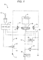
- Fig. 1 is a diagram illustrating a hydraulic circuit in a normal state of a hydraulic system 41 according to an embodiment of the present invention.
- the hydraulic system 41 includes a main circuit for supplying an operating pressure to an actuator 47 and a pilot circuit for operating the main circuit.
- the main circuit includes a hydraulic pump 46, a motor 48, a control valve 45, a pressure-compensated flow regulating valve 52, and a relief valve 55.
- the pilot circuit includes an operation lever 42, a controller 43, an electromagnetic proportional valve 44, a pilot pressure unloading solenoid valve 50, and an emergency operation activation switch 80 (see Figs. 3 and 5 ). That is, an electric operation system is applied to the pilot circuit.
- the pilot circuit constitutes a pilot pressure supply unit for supplying a pilot pressure to the control valve 45.
- the pilot pressure unloading solenoid valve 50 and the emergency operation activation switch 80 constitute a pilot pressure switching unit for switching the pilot circuit between an on-loading state and an unloading state.
- the operation lever 42 converts an operation direction and an operation amount into an operation electric signal, and outputs the operation electric signal to the controller 43.
- the controller 43 receives the operation electric signal of the operation lever 42 and outputs a drive electric signal to the corresponding electromagnetic proportional valve 44.
- the electromagnetic proportional valve 44 receives the drive electric signal from the controller 43, generates a pilot pressure proportional to the drive electric signal, and supplies the pilot pressure to the control valve 45.
- the pilot pressure unloading solenoid valve 50 supplies an electromagnetic proportional valve supply pressure from a pilot pressure source 51 to the electromagnetic proportional valves 44 and 44 via a pilot oil passage 82.
- the two electromagnetic proportional valves 44 are disposed corresponding to a driving direction of the actuator 47.
- a drive electric signal is output from the controller 43.
- the electromagnetic proportional valve 44 has a detent-type emergency manual operation function and includes, for example, an emergency operation screw as a manual operation unit.
- an operator can compulsorily open an oil passage of the electromagnetic proportional valve 44.
- a pilot pressure is supplied to the control valve 45.
- a driving direction of the control valve 45 is switched by the pilot pressure from the electromagnetic proportional valve 44, and the control valve 45 controls a pressure oil from the hydraulic pump 46 and supplies the pressure oil to the actuator 47.
- a variable capacity pump is adopted as the hydraulic pump 46.
- the hydraulic pump 46 is controlled such that a discharge amount during an emergency operation is smaller than that in a normal state.
- an actual construction machine includes a plurality of actuators, and includes a control valve and an electromagnetic proportional valve corresponding to each of the actuators.
- a control valve and an electromagnetic proportional valve corresponding to each of the actuators.
- only one actuator 47 is illustrated in order to simplify description of an operation during an emergency operation.
- an energization state of the pilot pressure unloading solenoid valve 50 is switched by a drive electric signal from the controller 43. That is, when the operation lever 42 is in a neutral state, the pilot pressure unloading solenoid valve 50 is not energized by the controller 43. At this time, a tank port of the pilot pressure unloading solenoid valve 50 and an output port communicate with each other, and the pilot oil passage 82 is connected to a tank. As a result, the pilot circuit is in an unloading state.
- the pilot pressure unloading solenoid valve 50 is energized by the controller 43.
- a supply port and the output port of the pilot pressure unloading solenoid valve 50 communicate with each other, and the pilot oil passage 82 is connected to the pilot pressure source 51.
- the pilot circuit is in an on-loading state. That is, an electromagnetic proportional valve supply pressure is supplied to the electromagnetic proportional valve 44 via the pilot oil passage 82.
- the pressure-compensated flow regulating valve 52 is interposed between a pump oil passage 53 and a tank oil passage 54 and controls a flow rate of a flowing working oil.
- the relief valve 55 is interposed between the pump oil passage 53 and the tank oil passage 54 and operates when an oil pressure exceeds a set pressure to prevent an abnormal rise in pressure.
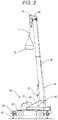
- Fig. 2 is a diagram illustrating an example of a mobile crane 60 on which the above-described hydraulic system 41 is mounted.
- the mobile crane 60 is in a crane working posture in which a jack cylinder 63 of an outrigger 62 disposed at the front and rear of a lower frame 61 extends, and the whole of the mobile crane 60 is jacked up.
- a revolving frame 64 is mounted on an upper surface of the lower frame 61.
- the revolving frame 64 is freely rotatable with respect to the lower frame 61.
- a telescopic boom 65 is connected to the revolving frame 64 by a pin 66.
- the telescopic boom 65 is freely raised or lowered with respect to the revolving frame 64.
- the telescopic boom 65 is expanded or contracted by a telescopic cylinder disposed therein.
- the telescopic boom 65 is raised or lowered by a derricking cylinder 67 interposed between the revolving frame 64 and the telescopic boom 65.
- a wire rope 68 is unreeled from a winch (not illustrated) disposed in the revolving frame 64 and led to a telescopic boom distal end 69 along a rear surface of the telescopic boom 65. Furthermore, the wire rope 68 is stretched around a sheave 70 of the telescopic boom distal end 69, and a hook 71 is hung from a distal end of the wire rope 68. A hanging load 72 is hung from the hook 71.
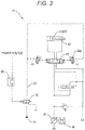
- Fig. 3 is a diagram illustrating an example of a hydraulic circuit during an emergency operation of the hydraulic system 41.
- an emergency operation selection switch 74 (see Fig. 5 ) disposed in the cab 73, the hydraulic system 41 is switched from a hydraulic circuit in a normal state (see Fig. 1 ) to a hydraulic circuit during an emergency operation (see Fig. 3 ) .
- a detent-type switch is used as the emergency operation selection switch 74. That is, in the hydraulic system 41, when the emergency operation selection switch 74 is operated, the hydraulic circuit during an emergency operation is held.
- an energization state of the pilot pressure unloading solenoid valve 50 is switched by the emergency operation activation switch 80 (see Fig. 5 ) instead of the controller 43 (see Fig. 1 ).
- the emergency operation activation switch 80 is activated in a case where the controller 43 cannot control the electromagnetic proportional valve 44.
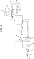
- the emergency operation activation switch 80 is disposed in the cab 73.
- the emergency operation activation switch 80 is disposed on a front operation panel of the cab 73 so as to be easily operated.
- a momentary type switch is used for the emergency operation activation switch 80. That is, only when the emergency operation activation switch 80 is operated, the pilot pressure unloading solenoid valve 50 is energized, and the pilot circuit is in an on-loading state.
- an operator switches the hydraulic system 41 from a hydraulic circuit in a normal state (see Fig. 1 ) to a hydraulic circuit during an emergency operation (see Fig. 3 ).
- the controller 43 is thereby electrically cut off from the hydraulic system 41.
- the discharge amount of the hydraulic pump 46 is switched to a small amount side. That is, the hydraulic pump 46 makes the supply amount of a working oil during an emergency operation during which the electromagnetic proportional valve 44 is manually opened smaller than the supply amount of the working oil in a normal state during which the electromagnetic proportional valve 44 is controlled by the controller 43.
- FIG. 4 illustrates the electromagnetic proportional valve 44d including an emergency operation screw 81 as an example of an electromagnetic proportional valve with a detent-type emergency manual operation function.
- the operator can fix an oil passage in the electromagnetic proportional valve 44d in an opened state.
- the electromagnetic proportional valve 44d is disposed on the revolving frame 64. Therefore, the operator needs to come out of the cab 73 to the revolving frame 64 and to perform a detent operation (manually opening operation).
- the pilot pressure unloading solenoid valve 50 is in a non-energization state because the emergency operation activation switch 80 is not operated, and is on a cutoff side (a state in which an output port and a tank port communicate with each other). Therefore, an electromagnetic proportional valve supply pressure of the pilot pressure source 51 has not come to the electromagnetic proportional valve 44d. That is, the pilot circuit is in an unloading state. Therefore, even if the operator directly performs the detent operation of the electromagnetic proportional valve 44d on the revolving frame 64, the control valve 45 is not switched, and the derricking cylinder 67 does not move to a lowering side. Therefore, the operator's safety is secured.
- the operator returns to the cab 73 and operates the emergency operation activation switch 80.
- the pilot pressure unloading solenoid valve 50 is energized from a power source via the emergency operation activation switch 80.
- the pilot pressure unloading solenoid valve 50 is switched to a communication side (state in which the output port and the supply port communicate with each other), and the pilot circuit is in an on-loading state.
- an electromagnetic proportional valve supply pressure of the pilot pressure source 51 is applied to the electromagnetic proportional valve 44d on a lower side via the pilot oil passage 82.
- a flow path of the electromagnetic proportional valve 44d on a lower side has already been manually opened. Therefore, the electromagnetic proportional valve supply pressure directly acts on the control valve 45 to switch the control valve 45 to a lower side. Then, a working oil discharged from the hydraulic pump 46 enters a contracting side oil chamber 83 of the derricking cylinder 67 via the control valve 45, and the derricking cylinder 67 starts a contracting operation. At this time, the discharge amount of the hydraulic pump 46 is switched to a small amount side, and the contracting operation of the derricking cylinder 67 is performed at a low speed. Therefore, the derricking cylinder 67 can be safely driven.
- the telescopic boom 65 falls.
- An operator operates the emergency operation activation switch 80 until the hanging load 72 is sufficiently away from the cab 73 or an upper portion of the lower frame 61 to make the telescopic boom 65 fall. Thereafter, the operator returns the emergency operation screw 81 of the electromagnetic proportional valve 44d to close the oil passage. Then, by returning the emergency operation selection switch 74 in the cab 73 to a normal side and lowering a winch that can be operated normally, the hanging load 72 can be lowered to the ground.
- the operator controls the pilot circuit such that the pilot circuit is in an unloading state, and then manually opens the electromagnetic proportional valve 44d corresponding to a desired moving direction of the actuator 47.
- the pilot pressure unloading solenoid valve 50 is controlled such that the pilot circuit is in an on-loading state, a pilot pressure is applied to the control valve 45, and the control valve 45 is thereby switched.
- the working oil of the hydraulic pump 46 is supplied to the actuator 47 to drive the actuator 47 in the desired moving direction.
- the hydraulic system 41 includes the hydraulic pump 46, the control valve 45 for supplying an operating pressure from the hydraulic pump 46 to the actuator 47 of a working machine, and an electric operation system (pilot pressure supply unit) for supplying a pilot pressure to the control valve 45.
- the electric operation system includes: the electromagnetic proportional valve 44 that has a detent-type emergency manual operation function with which the pilot oil passage 82 can be opened manually and generates a pilot pressure for the control valve 45; the controller 43 for controlling the degree of opening of the electromagnetic proportional valve 44 in accordance with an operation of an operation lever 42; and the pilot pressure switching unit for switching an oil pressure state of the pilot pressure supply unit between an on-loading state and an unloading state.
- the pilot pressure switching unit controls a pilot pressure such that the pilot pressure is in an unloading state when the electromagnetic proportional valve 44 is manually opened, and controls the pilot pressure such that the pilot pressure is in an on-loading state after the electromagnetic proportional valve 44 is manually opened.
- the pilot pressure switching unit includes: the pilot pressure unloading solenoid valve 50 for switching a pilot pressure between an on-loading state and an unloading state by energization; and the emergency operation activation switch 80 that is activated in a case where the electromagnetic proportional valve 44 cannot be controlled by the controller 43 and controls an energization state of the pilot pressure unloading solenoid valve 50.
- the hydraulic system for driving the actuator 47 (derricking cylinder 67) of the mobile crane has been described.
- the present invention can also be applied to a hydraulic system of another actuator (for example, a telescopic cylinder).
- the present invention can also be applied to a hydraulic system of a working machine other than a mobile crane.
Landscapes
- Engineering & Computer Science (AREA)
- Mechanical Engineering (AREA)
- Physics & Mathematics (AREA)
- Fluid Mechanics (AREA)
- General Engineering & Computer Science (AREA)
- Chemical & Material Sciences (AREA)
- Analytical Chemistry (AREA)
- Fluid-Pressure Circuits (AREA)
- Automation & Control Theory (AREA)
- Control And Safety Of Cranes (AREA)
Abstract
Description
- The present invention relates to a hydraulic system of a working machine, and particularly to a hydraulic system including an electric operation system for electrically controlling a control valve of the hydraulic system.
- In recent years, for an operation system of a hydraulic working machine, an electric operation system for electrically controlling a control valve of a hydraulic system has been used. In the electric operation system, an electric signal from an operation lever is input to a controller, and an electromagnetic proportional valve operates according to the electric signal from the controller. By the operation of the electromagnetic proportional valve, a pilot pressure of the control valve of the hydraulic system is controlled.
- The electric operation system can be subjected to advanced control by causing a controller to execute control logic and is becoming an important technique for responding to a high demand such as energy saving, low noise, or optimum control for a hydraulic working machine in recent years.
- In the electric operation system, when an electric circuit portion has failed, a controller cannot control an electromagnetic proportional valve. Therefore, the electric operation system preferably includes an emergency operation device for dealing with a failure (for example, Patent Literature 1).
Fig. 6 illustrates an example of the electric operation system including the emergency operation device. - In the electric operation system illustrated in
Fig. 6 , in a normal state, when an operation lever 9 of anoperation box 20 is operated, a drive electric signal based on the operation is output from acontroller 2, and input to an electromagnetic proportional valve 4 via anamplifier 3. A pilot pressure is controlled by an operation of the electromagnetic proportional valve 4, acontrol valve 27 is switched, and anactuator 5 is thereby driven. - When a failure such as disconnection occurs in an electric circuit portion of the electric operation system, a power
source changeover switch 22 is switched to an emergency operation side. Anemergency operation switch 21 built in theoperation box 20 is switched in conjunction with the operation of the operation lever 9, one of the electromagnetic proportional valves 4 is energized, and a pilot pressure is thereby supplied to thecontrol valve 27 to drive theactuator 5. - By the way, the emergency operation device illustrated in
Fig. 6 can deal with a case where the electromagnetic proportional valve 4 cannot be controlled due to a failure of an electric circuit portion, but cannot deal with a case where adhesion due to disconnection or contamination occurs and the electromagnetic proportional valve 4 itself does not function. - For such a failure of an electromagnetic proportional valve itself, the electromagnetic proportional valve has an emergency manual operation function. In this case, an operator directly activates an emergency manual operation function of an electromagnetic proportional valve to be operated, opens an oil passage of the electromagnetic proportional valve, and thereby can supply a desired pilot pressure to a control valve to drive an actuator.
- The electromagnetic proportional valve with an emergency manual operation function includes a detent-type valve and a momentary type valve. An electromagnetic proportional valve that can be fixed in a state where a flow path thereof is opened is referred to as a detent-type valve, and an electromagnetic proportional valve that cannot be fixed in the opening state is referred to as a momentary type valve. For example, an emergency operation screw is used in the detent-type valve, and a push pin (pin biased in a direction opposite to a pushing direction) is used in the momentary type valve.
- Patent Literature 1:
JP 2000-344466 A - Normally, an electromagnetic proportional valve is disposed on a frame of a working machine outside a cab of the working machine. During work with the working machine, a pilot circuit including the electromagnetic proportional valve is in an on-loading state (a state where a pilot oil pressure is applied). In a case of using an emergency manual operation function of the electromagnetic proportional valve, an operator performs work outside the cab. Furthermore, at the same time as performing an operation to directly open an oil passage of the electromagnetic proportional valve, a pilot pressure is supplied to a control valve, and an actuator starts to operate. Therefore, this is very dangerous.
- An object of the present invention is to provide a hydraulic system with which an operator can safely perform work during an emergency operation even in a case where an electromagnetic proportional valve itself has failed. Solutions to Problems
- The hydraulic system according to the present invention includes: a hydraulic pump; a control valve for supplying an operating pressure from the hydraulic pump to an actuator of a working machine; and a pilot pressure supply unit for supplying a pilot pressure for the control valve, and is characterized in that
the pilot pressure supply unit includes: - an electromagnetic proportional valve that has a detent-type emergency manual operation function capable of manually opening a pilot oil passage and generates a pilot pressure to the control valve;
- a controller for controlling the degree of opening of the electromagnetic proportional valve in accordance with an operation of an operation lever; and
- a pilot pressure switching unit for switching the pilot pressure supply unit between an on-loading state and an unloading state, and
- the pilot pressure switching unit controls a pilot pressure such that the pilot pressure is in the unloading state when the electromagnetic proportional valve is manually opened, and controls the pilot pressure such that the pilot pressure is in the on-loading state after the electromagnetic proportional valve is manually opened.
- With the hydraulic system according to the present invention, an operator can safely perform work during an emergency operation even in a case where an electromagnetic proportional valve itself has failed.
-
-
Fig. 1 is a diagram illustrating an example of a hydraulic circuit in a normal state of a hydraulic system according to an embodiment of the present invention. -
Fig. 2 is a diagram illustrating an example of a mobile crane on which the hydraulic system according to the embodiment is mounted. -
Fig. 3 is a diagram illustrating an example of a hydraulic circuit during an emergency operation of the hydraulic system. -
Fig. 4 is a diagram illustrating a main part of an electromagnetic proportional valve with a detent-type emergency manual operation function. -
Fig. 5 is a diagram illustrating an example of an emergency operation activation switch disposed in a cab. -
Fig. 6 is a diagram illustrating a circuit of an emergency operation device disclosed inPatent Literature 1. -
Fig. 1 is a diagram illustrating a hydraulic circuit in a normal state of ahydraulic system 41 according to an embodiment of the present invention. - The
hydraulic system 41 includes a main circuit for supplying an operating pressure to anactuator 47 and a pilot circuit for operating the main circuit. The main circuit includes ahydraulic pump 46, amotor 48, acontrol valve 45, a pressure-compensatedflow regulating valve 52, and arelief valve 55. The pilot circuit includes anoperation lever 42, acontroller 43, an electromagneticproportional valve 44, a pilot pressure unloadingsolenoid valve 50, and an emergency operation activation switch 80 (seeFigs. 3 and5 ). That is, an electric operation system is applied to the pilot circuit. - In the
hydraulic system 41, the pilot circuit constitutes a pilot pressure supply unit for supplying a pilot pressure to thecontrol valve 45. The pilot pressure unloadingsolenoid valve 50 and the emergencyoperation activation switch 80 constitute a pilot pressure switching unit for switching the pilot circuit between an on-loading state and an unloading state. - The
operation lever 42 converts an operation direction and an operation amount into an operation electric signal, and outputs the operation electric signal to thecontroller 43. Thecontroller 43 receives the operation electric signal of theoperation lever 42 and outputs a drive electric signal to the corresponding electromagneticproportional valve 44. The electromagneticproportional valve 44 receives the drive electric signal from thecontroller 43, generates a pilot pressure proportional to the drive electric signal, and supplies the pilot pressure to thecontrol valve 45. The pilot pressure unloadingsolenoid valve 50 supplies an electromagnetic proportional valve supply pressure from apilot pressure source 51 to the electromagneticproportional valves pilot oil passage 82. - As illustrated in
Fig. 1 , the two electromagneticproportional valves 44 are disposed corresponding to a driving direction of theactuator 47. To each of the electromagneticproportional valves 44, a drive electric signal is output from thecontroller 43. The electromagneticproportional valve 44 has a detent-type emergency manual operation function and includes, for example, an emergency operation screw as a manual operation unit. During an emergency operation, by directly operating an emergency operation unit, an operator can compulsorily open an oil passage of the electromagneticproportional valve 44. As a result, a pilot pressure is supplied to thecontrol valve 45. - A driving direction of the
control valve 45 is switched by the pilot pressure from the electromagneticproportional valve 44, and thecontrol valve 45 controls a pressure oil from thehydraulic pump 46 and supplies the pressure oil to theactuator 47. As illustrated inFig. 1 , a variable capacity pump is adopted as thehydraulic pump 46. As described later, thehydraulic pump 46 is controlled such that a discharge amount during an emergency operation is smaller than that in a normal state. - Note that an actual construction machine includes a plurality of actuators, and includes a control valve and an electromagnetic proportional valve corresponding to each of the actuators. In
Fig. 1 , only oneactuator 47 is illustrated in order to simplify description of an operation during an emergency operation. - As illustrated in
Fig. 1 , in a normal state, an energization state of the pilot pressure unloadingsolenoid valve 50 is switched by a drive electric signal from thecontroller 43. That is, when theoperation lever 42 is in a neutral state, the pilot pressure unloadingsolenoid valve 50 is not energized by thecontroller 43. At this time, a tank port of the pilot pressure unloadingsolenoid valve 50 and an output port communicate with each other, and thepilot oil passage 82 is connected to a tank. As a result, the pilot circuit is in an unloading state. - Meanwhile, when the
operation lever 42 is operated, the pilot pressure unloadingsolenoid valve 50 is energized by thecontroller 43. At this time, a supply port and the output port of the pilot pressure unloadingsolenoid valve 50 communicate with each other, and thepilot oil passage 82 is connected to thepilot pressure source 51. As a result, the pilot circuit is in an on-loading state. That is, an electromagnetic proportional valve supply pressure is supplied to the electromagneticproportional valve 44 via thepilot oil passage 82. - The pressure-compensated
flow regulating valve 52 is interposed between apump oil passage 53 and atank oil passage 54 and controls a flow rate of a flowing working oil. Therelief valve 55 is interposed between thepump oil passage 53 and thetank oil passage 54 and operates when an oil pressure exceeds a set pressure to prevent an abnormal rise in pressure. -
Fig. 2 is a diagram illustrating an example of amobile crane 60 on which the above-describedhydraulic system 41 is mounted. InFig. 2 , themobile crane 60 is in a crane working posture in which ajack cylinder 63 of anoutrigger 62 disposed at the front and rear of alower frame 61 extends, and the whole of themobile crane 60 is jacked up. - A revolving
frame 64 is mounted on an upper surface of thelower frame 61. The revolvingframe 64 is freely rotatable with respect to thelower frame 61. Atelescopic boom 65 is connected to the revolvingframe 64 by apin 66. Thetelescopic boom 65 is freely raised or lowered with respect to the revolvingframe 64. Thetelescopic boom 65 is expanded or contracted by a telescopic cylinder disposed therein. Thetelescopic boom 65 is raised or lowered by aderricking cylinder 67 interposed between the revolvingframe 64 and thetelescopic boom 65. - A
wire rope 68 is unreeled from a winch (not illustrated) disposed in the revolvingframe 64 and led to a telescopic boomdistal end 69 along a rear surface of thetelescopic boom 65. Furthermore, thewire rope 68 is stretched around asheave 70 of the telescopic boomdistal end 69, and ahook 71 is hung from a distal end of thewire rope 68. A hangingload 72 is hung from thehook 71. - In the
mobile crane 60, it is assumed that an electromagnetic proportional valve (electromagnetic proportional valve for contracting the derricking cylinder 67) on a lower side of thederricking cylinder 67 suddenly stops operating by adhesion due to disconnection or contamination during work with the crane. Even in this situation, it is possible to lower the hangingload 72 downward by winding down the winch. However, in the crane posture illustrated inFig. 2 , the hangingload 72 hits acab 73. In addition, it is dangerous to leave the hangingload 72 while the hangingload 72 is hung. Therefore, it is necessary to lower thederricking cylinder 67 by an emergency operation to lower the hangingload 72 to the ground. -
Fig. 3 is a diagram illustrating an example of a hydraulic circuit during an emergency operation of thehydraulic system 41. By operation of an emergency operation selection switch 74 (seeFig. 5 ) disposed in thecab 73, thehydraulic system 41 is switched from a hydraulic circuit in a normal state (seeFig. 1 ) to a hydraulic circuit during an emergency operation (seeFig. 3 ) . - Note that a detent-type switch is used as the emergency
operation selection switch 74. That is, in thehydraulic system 41, when the emergencyoperation selection switch 74 is operated, the hydraulic circuit during an emergency operation is held. - As illustrated in
Fig. 3 , in thehydraulic system 41, an energization state of the pilot pressure unloadingsolenoid valve 50 is switched by the emergency operation activation switch 80 (seeFig. 5 ) instead of the controller 43 (seeFig. 1 ). - That is, the emergency
operation activation switch 80 is activated in a case where thecontroller 43 cannot control the electromagneticproportional valve 44. The emergencyoperation activation switch 80 is disposed in thecab 73. The emergencyoperation activation switch 80 is disposed on a front operation panel of thecab 73 so as to be easily operated. - Note that a momentary type switch is used for the emergency
operation activation switch 80. That is, only when the emergencyoperation activation switch 80 is operated, the pilot pressure unloadingsolenoid valve 50 is energized, and the pilot circuit is in an on-loading state. - An emergency operation of the
hydraulic system 41 is performed in the following procedure. Here, a case where thederricking cylinder 67 is lowered by the emergency operation will be described. - First, by operation of the emergency
operation selection switch 74 in thecab 73, an operator switches thehydraulic system 41 from a hydraulic circuit in a normal state (seeFig. 1 ) to a hydraulic circuit during an emergency operation (seeFig. 3 ). Thecontroller 43 is thereby electrically cut off from thehydraulic system 41. - At this time, with the operation of the emergency
operation selection switch 74, the discharge amount of thehydraulic pump 46 is switched to a small amount side. That is, thehydraulic pump 46 makes the supply amount of a working oil during an emergency operation during which the electromagneticproportional valve 44 is manually opened smaller than the supply amount of the working oil in a normal state during which the electromagneticproportional valve 44 is controlled by thecontroller 43. - Next, the operator opens an electromagnetic
proportional valve 44d on a lower side of thederricking cylinder 67 by an emergency manual operation function.Fig. 4 illustrates the electromagneticproportional valve 44d including anemergency operation screw 81 as an example of an electromagnetic proportional valve with a detent-type emergency manual operation function. By directly operating theemergency operation screw 81, the operator can fix an oil passage in the electromagneticproportional valve 44d in an opened state. The electromagneticproportional valve 44d is disposed on the revolvingframe 64. Therefore, the operator needs to come out of thecab 73 to the revolvingframe 64 and to perform a detent operation (manually opening operation). - At this time, the pilot pressure unloading
solenoid valve 50 is in a non-energization state because the emergencyoperation activation switch 80 is not operated, and is on a cutoff side (a state in which an output port and a tank port communicate with each other). Therefore, an electromagnetic proportional valve supply pressure of thepilot pressure source 51 has not come to the electromagneticproportional valve 44d. That is, the pilot circuit is in an unloading state. Therefore, even if the operator directly performs the detent operation of the electromagneticproportional valve 44d on the revolvingframe 64, thecontrol valve 45 is not switched, and thederricking cylinder 67 does not move to a lowering side. Therefore, the operator's safety is secured. - Next, the operator returns to the
cab 73 and operates the emergencyoperation activation switch 80. Then, the pilot pressure unloadingsolenoid valve 50 is energized from a power source via the emergencyoperation activation switch 80. The pilot pressure unloadingsolenoid valve 50 is switched to a communication side (state in which the output port and the supply port communicate with each other), and the pilot circuit is in an on-loading state. As a result, an electromagnetic proportional valve supply pressure of thepilot pressure source 51 is applied to the electromagneticproportional valve 44d on a lower side via thepilot oil passage 82. - A flow path of the electromagnetic
proportional valve 44d on a lower side has already been manually opened. Therefore, the electromagnetic proportional valve supply pressure directly acts on thecontrol valve 45 to switch thecontrol valve 45 to a lower side. Then, a working oil discharged from thehydraulic pump 46 enters a contractingside oil chamber 83 of thederricking cylinder 67 via thecontrol valve 45, and thederricking cylinder 67 starts a contracting operation. At this time, the discharge amount of thehydraulic pump 46 is switched to a small amount side, and the contracting operation of thederricking cylinder 67 is performed at a low speed. Therefore, thederricking cylinder 67 can be safely driven. - In the
mobile crane 60, when thederricking cylinder 67 contracts, thetelescopic boom 65 falls. An operator operates the emergencyoperation activation switch 80 until the hangingload 72 is sufficiently away from thecab 73 or an upper portion of thelower frame 61 to make thetelescopic boom 65 fall. Thereafter, the operator returns theemergency operation screw 81 of the electromagneticproportional valve 44d to close the oil passage. Then, by returning the emergencyoperation selection switch 74 in thecab 73 to a normal side and lowering a winch that can be operated normally, the hangingload 72 can be lowered to the ground. - That is, during an emergency operation, the operator controls the pilot circuit such that the pilot circuit is in an unloading state, and then manually opens the electromagnetic
proportional valve 44d corresponding to a desired moving direction of theactuator 47. Thereafter, by operation of the emergencyoperation activation switch 80 in thecab 73 of the crane, the pilot pressure unloadingsolenoid valve 50 is controlled such that the pilot circuit is in an on-loading state, a pilot pressure is applied to thecontrol valve 45, and thecontrol valve 45 is thereby switched. As a result, the working oil of thehydraulic pump 46 is supplied to theactuator 47 to drive theactuator 47 in the desired moving direction. - As described above, the
hydraulic system 41 according to the embodiment includes thehydraulic pump 46, thecontrol valve 45 for supplying an operating pressure from thehydraulic pump 46 to theactuator 47 of a working machine, and an electric operation system (pilot pressure supply unit) for supplying a pilot pressure to thecontrol valve 45. The electric operation system includes: the electromagneticproportional valve 44 that has a detent-type emergency manual operation function with which thepilot oil passage 82 can be opened manually and generates a pilot pressure for thecontrol valve 45; thecontroller 43 for controlling the degree of opening of the electromagneticproportional valve 44 in accordance with an operation of anoperation lever 42; and the pilot pressure switching unit for switching an oil pressure state of the pilot pressure supply unit between an on-loading state and an unloading state. The pilot pressure switching unit controls a pilot pressure such that the pilot pressure is in an unloading state when the electromagneticproportional valve 44 is manually opened, and controls the pilot pressure such that the pilot pressure is in an on-loading state after the electromagneticproportional valve 44 is manually opened. - Specifically, the pilot pressure switching unit includes: the pilot pressure unloading
solenoid valve 50 for switching a pilot pressure between an on-loading state and an unloading state by energization; and the emergencyoperation activation switch 80 that is activated in a case where the electromagneticproportional valve 44 cannot be controlled by thecontroller 43 and controls an energization state of the pilot pressure unloadingsolenoid valve 50. - With the
hydraulic system 41 according to the present embodiment, an operator can safely perform work during an emergency operation even in a case where the electromagneticproportional valve 44 itself has failed and does not operate by adhesion due to disconnection or contamination. Therefore, safety of a working machine is remarkably improved. - Hereinabove, the invention achieved by the present inventor has been specifically described based on the embodiment. However, the present invention is not limited to the above embodiment, and can be modified within a range not departing from the gist thereof.
- For example, in the embodiment, the hydraulic system for driving the actuator 47 (derricking cylinder 67) of the mobile crane has been described. However, the present invention can also be applied to a hydraulic system of another actuator (for example, a telescopic cylinder). In addition, the present invention can also be applied to a hydraulic system of a working machine other than a mobile crane.
- It should be considered that the embodiment disclosed here is illustrative in all respects and not restrictive. The scope of the present invention is defined not by the above description but by the claims and intends to include all modifications within meaning and scope equivalent to the claims.
- The disclosed content of the specification, drawings and abstract included in the Japanese application No.
2016-060951 filed on March 24, 2016 -
- 41 Hydraulic system
- 42 Operation lever
- 43 Controller
- 44 Electromagnetic proportional valve
- 45 Control valve
- 46 Hydraulic pump
- 47 Actuator
- 50 Pilot pressure unloading solenoid valve (pilot pressure switching unit)
- 80 Emergency operation activation switch (pilot pressure switching unit)
Claims (5)
- A hydraulic system comprising: a hydraulic pump; a control valve for supplying an operating pressure from the hydraulic pump to an actuator of a working machine; and a pilot pressure supply unit for supplying a pilot pressure to the control valve, wherein
the pilot pressure supply unit includes:an electromagnetic proportional valve that has a detent-type emergency manual operation function capable of manually opening a pilot oil passage and generates a pilot pressure for the control valve;a controller for controlling a degree of opening of the electromagnetic proportional valve in accordance with an operation of an operation lever; anda pilot pressure switching unit for switching the pilot pressure supply unit between an on-loading state and an unloading state, andthe pilot pressure switching unit controls a pilot pressure supply unit such that the pilot pressure supply unit is in the unloading state when the electromagnetic proportional valve is manually opened, and controls the pilot pressure supply unit such that the pilot pressure supply unit is in the on-loading state after the electromagnetic proportional valve is manually opened. - The hydraulic system according to claim 1, wherein
the pilot pressure switching unit includes:a pilot pressure unloading solenoid valve for switching a pilot pressure between the on-loading state and the unloading state by energization; andan emergency operation activation switch that is activated in a case where the electromagnetic proportional valve cannot be controlled by the controller and controls an energization state of the pilot pressure unloading solenoid valve. - The hydraulic system according to claim 2, wherein the emergency operation activation switch is a momentary type switch.
- The hydraulic system according to claim 2, wherein the emergency operation activation switch is disposed in a cab of the working machine.
- The hydraulic system according to claim 1, wherein the hydraulic pump makes a supply amount of a working oil during an emergency operation during which the electromagnetic proportional valve is manually opened smaller than a supply amount of the working oil in a normal state during which the electromagnetic proportional valve is controlled by the controller.
Applications Claiming Priority (2)
| Application Number | Priority Date | Filing Date | Title |
|---|---|---|---|
| JP2016060951 | 2016-03-24 | ||
| PCT/JP2017/012021 WO2017164371A1 (en) | 2016-03-24 | 2017-03-24 | Hydraulic system |
Publications (3)
| Publication Number | Publication Date |
|---|---|
| EP3434913A1 true EP3434913A1 (en) | 2019-01-30 |
| EP3434913A4 EP3434913A4 (en) | 2019-11-20 |
| EP3434913B1 EP3434913B1 (en) | 2021-05-12 |
Family
ID=59900418
Family Applications (1)
| Application Number | Title | Priority Date | Filing Date |
|---|---|---|---|
| EP17770411.1A Active EP3434913B1 (en) | 2016-03-24 | 2017-03-24 | Hydraulic system |
Country Status (5)
| Country | Link |
|---|---|
| US (1) | US10837473B2 (en) |
| EP (1) | EP3434913B1 (en) |
| JP (1) | JP6856065B2 (en) |
| CN (1) | CN108779791B (en) |
| WO (1) | WO2017164371A1 (en) |
Families Citing this family (6)
| Publication number | Priority date | Publication date | Assignee | Title |
|---|---|---|---|---|
| WO2017164370A1 (en) * | 2016-03-24 | 2017-09-28 | 株式会社タダノ | Failure diagnosis device |
| JP7357465B2 (en) * | 2019-05-22 | 2023-10-06 | 川崎重工業株式会社 | hydraulic system |
| JP7756585B2 (en) * | 2022-03-24 | 2025-10-20 | 株式会社モリタホールディングス | Ladder/boom equipped vehicle |
| WO2023232331A1 (en) * | 2022-06-03 | 2023-12-07 | Winz Baggerarbeiten Gmbh | Valve arrangement for mobile working machines comprising a hydraulic consumer |
| EP4311945A1 (en) * | 2022-07-28 | 2024-01-31 | Manitowoc Crane Group France SAS | Emergency operating valve block for a mobile crane |
| CN115789140B (en) * | 2022-12-20 | 2025-08-01 | 威海人合机电股份有限公司 | Emergency brake control system of box type ship lift |
Family Cites Families (14)
| Publication number | Priority date | Publication date | Assignee | Title |
|---|---|---|---|---|
| DE2533829C2 (en) * | 1975-07-29 | 1985-01-10 | Robert Bosch Gmbh, 7000 Stuttgart | Electro-hydraulic control device |
| JPS62151603A (en) * | 1985-12-23 | 1987-07-06 | Kobe Steel Ltd | Hydraulic control circuit |
| JP3469279B2 (en) * | 1993-11-04 | 2003-11-25 | 石川島建機株式会社 | Hydraulic circuit |
| JP2972530B2 (en) * | 1994-11-16 | 1999-11-08 | 新キャタピラー三菱株式会社 | Work machine control device for construction machinery |
| JP3709241B2 (en) * | 1996-05-23 | 2005-10-26 | Smc株式会社 | Solenoid valve with switch |
| JP2000344466A (en) | 1999-06-07 | 2000-12-12 | Tadano Ltd | Operating device for working vehicle |
| JP2003184810A (en) * | 2001-12-19 | 2003-07-03 | Shin Caterpillar Mitsubishi Ltd | Hydraulic circuit in working machinery |
| DE10344458B3 (en) * | 2003-09-25 | 2005-05-25 | Festo Ag & Co. | Pilot operated multiway valve |
| DE102006007935A1 (en) * | 2006-02-21 | 2007-10-25 | Liebherr France Sas | Control device and hydraulic pilot control |
| JP2009263061A (en) | 2008-04-24 | 2009-11-12 | Ihi Corp | Hydraulic circuit for controlling crane |
| CN101368584A (en) * | 2008-09-28 | 2009-02-18 | 哈尔滨工业大学 | New emergency protection mechanism for three-stage electro-hydraulic servo valve |
| KR20100134332A (en) * | 2009-06-15 | 2010-12-23 | 볼보 컨스트럭션 이큅먼트 에이비 | Control lever lock of construction equipment |
| JP5373756B2 (en) * | 2010-12-22 | 2013-12-18 | 日立建機株式会社 | Relief pressure control device for hydraulic working machine |
| GB2514112C (en) * | 2013-05-13 | 2016-11-30 | Caterpillar Inc | Valve Arrangement |
-
2017
- 2017-03-24 JP JP2018507440A patent/JP6856065B2/en active Active
- 2017-03-24 CN CN201780017818.6A patent/CN108779791B/en active Active
- 2017-03-24 EP EP17770411.1A patent/EP3434913B1/en active Active
- 2017-03-24 WO PCT/JP2017/012021 patent/WO2017164371A1/en not_active Ceased
- 2017-03-24 US US16/085,797 patent/US10837473B2/en active Active
Also Published As
| Publication number | Publication date |
|---|---|
| WO2017164371A1 (en) | 2017-09-28 |
| US20190085876A1 (en) | 2019-03-21 |
| JP6856065B2 (en) | 2021-04-07 |
| CN108779791A (en) | 2018-11-09 |
| US10837473B2 (en) | 2020-11-17 |
| EP3434913B1 (en) | 2021-05-12 |
| EP3434913A4 (en) | 2019-11-20 |
| JPWO2017164371A1 (en) | 2019-01-31 |
| CN108779791B (en) | 2020-04-28 |
Similar Documents
| Publication | Publication Date | Title |
|---|---|---|
| EP3434913B1 (en) | Hydraulic system | |
| US10995778B2 (en) | Hydraulic system and emergency operation method | |
| US10041224B2 (en) | Liquid-pressure driving system | |
| US20160061228A1 (en) | Valve Arrangement for the Hydraulic Circuit of a Work Machine | |
| CN114212719B (en) | Control method of hydraulic system of protection winch | |
| JP2019534831A (en) | Hydraulic clamping system that variably responds to load load side shift | |
| WO2015146358A1 (en) | Hoist device for dump truck | |
| JP6593571B1 (en) | crane | |
| KR101688233B1 (en) | Anti-engine stall system for a heavy equipment | |
| JP3731775B2 (en) | Winch equipment for work equipment | |
| US10787345B2 (en) | Crane | |
| JP6520092B2 (en) | Crane operating device | |
| AU2016312887B2 (en) | Hydraulic controller for a hydraulically actuated liftable and lowerable hook of a crane | |
| CN104854281B (en) | For the controlled reduction for loading and the system and method for lifting | |
| JP2015086961A (en) | Lifting device with limit load switching function | |
| JP2015034617A (en) | Pump confluence circuit, and work machine | |
| KR102461679B1 (en) | Control system for construction machinery | |
| JP3939037B2 (en) | Hydraulic drive control device for work equipment | |
| KR20200002612A (en) | Apparatus for cargo crane | |
| JP2010190341A (en) | Fluid pressure circuit and working machine | |
| JP2003184804A (en) | Hydraulic control device | |
| JPH06136790A (en) | Drive controller for hydraulic machine | |
| JPH11255500A (en) | Emergency stop device for aerial work vehicles |
Legal Events
| Date | Code | Title | Description |
|---|---|---|---|
| STAA | Information on the status of an ep patent application or granted ep patent |
Free format text: STATUS: THE INTERNATIONAL PUBLICATION HAS BEEN MADE |
|
| PUAI | Public reference made under article 153(3) epc to a published international application that has entered the european phase |
Free format text: ORIGINAL CODE: 0009012 |
|
| STAA | Information on the status of an ep patent application or granted ep patent |
Free format text: STATUS: REQUEST FOR EXAMINATION WAS MADE |
|
| 17P | Request for examination filed |
Effective date: 20181015 |
|
| AK | Designated contracting states |
Kind code of ref document: A1 Designated state(s): AL AT BE BG CH CY CZ DE DK EE ES FI FR GB GR HR HU IE IS IT LI LT LU LV MC MK MT NL NO PL PT RO RS SE SI SK SM TR |
|
| AX | Request for extension of the european patent |
Extension state: BA ME |
|
| DAV | Request for validation of the european patent (deleted) | ||
| DAX | Request for extension of the european patent (deleted) | ||
| A4 | Supplementary search report drawn up and despatched |
Effective date: 20191022 |
|
| RIC1 | Information provided on ipc code assigned before grant |
Ipc: F15B 20/00 20060101AFI20191016BHEP Ipc: B66C 23/88 20060101ALI20191016BHEP Ipc: B66C 13/20 20060101ALI20191016BHEP |
|
| GRAP | Despatch of communication of intention to grant a patent |
Free format text: ORIGINAL CODE: EPIDOSNIGR1 |
|
| STAA | Information on the status of an ep patent application or granted ep patent |
Free format text: STATUS: GRANT OF PATENT IS INTENDED |
|
| INTG | Intention to grant announced |
Effective date: 20201201 |
|
| GRAS | Grant fee paid |
Free format text: ORIGINAL CODE: EPIDOSNIGR3 |
|
| GRAA | (expected) grant |
Free format text: ORIGINAL CODE: 0009210 |
|
| STAA | Information on the status of an ep patent application or granted ep patent |
Free format text: STATUS: THE PATENT HAS BEEN GRANTED |
|
| AK | Designated contracting states |
Kind code of ref document: B1 Designated state(s): AL AT BE BG CH CY CZ DE DK EE ES FI FR GB GR HR HU IE IS IT LI LT LU LV MC MK MT NL NO PL PT RO RS SE SI SK SM TR |
|
| REG | Reference to a national code |
Ref country code: GB Ref legal event code: FG4D |
|
| REG | Reference to a national code |
Ref country code: CH Ref legal event code: EP |
|
| REG | Reference to a national code |
Ref country code: DE Ref legal event code: R096 Ref document number: 602017038558 Country of ref document: DE |
|
| REG | Reference to a national code |
Ref country code: IE Ref legal event code: FG4D |
|
| REG | Reference to a national code |
Ref country code: AT Ref legal event code: REF Ref document number: 1392368 Country of ref document: AT Kind code of ref document: T Effective date: 20210615 |
|
| REG | Reference to a national code |
Ref country code: LT Ref legal event code: MG9D |
|
| REG | Reference to a national code |
Ref country code: AT Ref legal event code: MK05 Ref document number: 1392368 Country of ref document: AT Kind code of ref document: T Effective date: 20210512 |
|
| REG | Reference to a national code |
Ref country code: NL Ref legal event code: MP Effective date: 20210512 |
|
| PG25 | Lapsed in a contracting state [announced via postgrant information from national office to epo] |
Ref country code: HR Free format text: LAPSE BECAUSE OF FAILURE TO SUBMIT A TRANSLATION OF THE DESCRIPTION OR TO PAY THE FEE WITHIN THE PRESCRIBED TIME-LIMIT Effective date: 20210512 Ref country code: BG Free format text: LAPSE BECAUSE OF FAILURE TO SUBMIT A TRANSLATION OF THE DESCRIPTION OR TO PAY THE FEE WITHIN THE PRESCRIBED TIME-LIMIT Effective date: 20210812 Ref country code: AT Free format text: LAPSE BECAUSE OF FAILURE TO SUBMIT A TRANSLATION OF THE DESCRIPTION OR TO PAY THE FEE WITHIN THE PRESCRIBED TIME-LIMIT Effective date: 20210512 Ref country code: FI Free format text: LAPSE BECAUSE OF FAILURE TO SUBMIT A TRANSLATION OF THE DESCRIPTION OR TO PAY THE FEE WITHIN THE PRESCRIBED TIME-LIMIT Effective date: 20210512 Ref country code: LT Free format text: LAPSE BECAUSE OF FAILURE TO SUBMIT A TRANSLATION OF THE DESCRIPTION OR TO PAY THE FEE WITHIN THE PRESCRIBED TIME-LIMIT Effective date: 20210512 |
|
| PG25 | Lapsed in a contracting state [announced via postgrant information from national office to epo] |
Ref country code: GR Free format text: LAPSE BECAUSE OF FAILURE TO SUBMIT A TRANSLATION OF THE DESCRIPTION OR TO PAY THE FEE WITHIN THE PRESCRIBED TIME-LIMIT Effective date: 20210813 Ref country code: IS Free format text: LAPSE BECAUSE OF FAILURE TO SUBMIT A TRANSLATION OF THE DESCRIPTION OR TO PAY THE FEE WITHIN THE PRESCRIBED TIME-LIMIT Effective date: 20210912 Ref country code: LV Free format text: LAPSE BECAUSE OF FAILURE TO SUBMIT A TRANSLATION OF THE DESCRIPTION OR TO PAY THE FEE WITHIN THE PRESCRIBED TIME-LIMIT Effective date: 20210512 Ref country code: NO Free format text: LAPSE BECAUSE OF FAILURE TO SUBMIT A TRANSLATION OF THE DESCRIPTION OR TO PAY THE FEE WITHIN THE PRESCRIBED TIME-LIMIT Effective date: 20210812 Ref country code: PL Free format text: LAPSE BECAUSE OF FAILURE TO SUBMIT A TRANSLATION OF THE DESCRIPTION OR TO PAY THE FEE WITHIN THE PRESCRIBED TIME-LIMIT Effective date: 20210512 Ref country code: PT Free format text: LAPSE BECAUSE OF FAILURE TO SUBMIT A TRANSLATION OF THE DESCRIPTION OR TO PAY THE FEE WITHIN THE PRESCRIBED TIME-LIMIT Effective date: 20210913 Ref country code: SE Free format text: LAPSE BECAUSE OF FAILURE TO SUBMIT A TRANSLATION OF THE DESCRIPTION OR TO PAY THE FEE WITHIN THE PRESCRIBED TIME-LIMIT Effective date: 20210512 Ref country code: RS Free format text: LAPSE BECAUSE OF FAILURE TO SUBMIT A TRANSLATION OF THE DESCRIPTION OR TO PAY THE FEE WITHIN THE PRESCRIBED TIME-LIMIT Effective date: 20210512 |
|
| PG25 | Lapsed in a contracting state [announced via postgrant information from national office to epo] |
Ref country code: NL Free format text: LAPSE BECAUSE OF FAILURE TO SUBMIT A TRANSLATION OF THE DESCRIPTION OR TO PAY THE FEE WITHIN THE PRESCRIBED TIME-LIMIT Effective date: 20210512 |
|
| PG25 | Lapsed in a contracting state [announced via postgrant information from national office to epo] |
Ref country code: RO Free format text: LAPSE BECAUSE OF FAILURE TO SUBMIT A TRANSLATION OF THE DESCRIPTION OR TO PAY THE FEE WITHIN THE PRESCRIBED TIME-LIMIT Effective date: 20210512 Ref country code: ES Free format text: LAPSE BECAUSE OF FAILURE TO SUBMIT A TRANSLATION OF THE DESCRIPTION OR TO PAY THE FEE WITHIN THE PRESCRIBED TIME-LIMIT Effective date: 20210512 Ref country code: CZ Free format text: LAPSE BECAUSE OF FAILURE TO SUBMIT A TRANSLATION OF THE DESCRIPTION OR TO PAY THE FEE WITHIN THE PRESCRIBED TIME-LIMIT Effective date: 20210512 Ref country code: DK Free format text: LAPSE BECAUSE OF FAILURE TO SUBMIT A TRANSLATION OF THE DESCRIPTION OR TO PAY THE FEE WITHIN THE PRESCRIBED TIME-LIMIT Effective date: 20210512 Ref country code: EE Free format text: LAPSE BECAUSE OF FAILURE TO SUBMIT A TRANSLATION OF THE DESCRIPTION OR TO PAY THE FEE WITHIN THE PRESCRIBED TIME-LIMIT Effective date: 20210512 Ref country code: SM Free format text: LAPSE BECAUSE OF FAILURE TO SUBMIT A TRANSLATION OF THE DESCRIPTION OR TO PAY THE FEE WITHIN THE PRESCRIBED TIME-LIMIT Effective date: 20210512 Ref country code: SK Free format text: LAPSE BECAUSE OF FAILURE TO SUBMIT A TRANSLATION OF THE DESCRIPTION OR TO PAY THE FEE WITHIN THE PRESCRIBED TIME-LIMIT Effective date: 20210512 |
|
| REG | Reference to a national code |
Ref country code: DE Ref legal event code: R097 Ref document number: 602017038558 Country of ref document: DE |
|
| PLBE | No opposition filed within time limit |
Free format text: ORIGINAL CODE: 0009261 |
|
| STAA | Information on the status of an ep patent application or granted ep patent |
Free format text: STATUS: NO OPPOSITION FILED WITHIN TIME LIMIT |
|
| 26N | No opposition filed |
Effective date: 20220215 |
|
| PG25 | Lapsed in a contracting state [announced via postgrant information from national office to epo] |
Ref country code: IS Free format text: LAPSE BECAUSE OF FAILURE TO SUBMIT A TRANSLATION OF THE DESCRIPTION OR TO PAY THE FEE WITHIN THE PRESCRIBED TIME-LIMIT Effective date: 20210912 Ref country code: AL Free format text: LAPSE BECAUSE OF FAILURE TO SUBMIT A TRANSLATION OF THE DESCRIPTION OR TO PAY THE FEE WITHIN THE PRESCRIBED TIME-LIMIT Effective date: 20210512 |
|
| PG25 | Lapsed in a contracting state [announced via postgrant information from national office to epo] |
Ref country code: IT Free format text: LAPSE BECAUSE OF FAILURE TO SUBMIT A TRANSLATION OF THE DESCRIPTION OR TO PAY THE FEE WITHIN THE PRESCRIBED TIME-LIMIT Effective date: 20210512 |
|
| PG25 | Lapsed in a contracting state [announced via postgrant information from national office to epo] |
Ref country code: MC Free format text: LAPSE BECAUSE OF FAILURE TO SUBMIT A TRANSLATION OF THE DESCRIPTION OR TO PAY THE FEE WITHIN THE PRESCRIBED TIME-LIMIT Effective date: 20210512 |
|
| REG | Reference to a national code |
Ref country code: CH Ref legal event code: PL |
|
| GBPC | Gb: european patent ceased through non-payment of renewal fee |
Effective date: 20220324 |
|
| REG | Reference to a national code |
Ref country code: BE Ref legal event code: MM Effective date: 20220331 |
|
| PG25 | Lapsed in a contracting state [announced via postgrant information from national office to epo] |
Ref country code: LU Free format text: LAPSE BECAUSE OF NON-PAYMENT OF DUE FEES Effective date: 20220324 Ref country code: LI Free format text: LAPSE BECAUSE OF NON-PAYMENT OF DUE FEES Effective date: 20220331 Ref country code: IE Free format text: LAPSE BECAUSE OF NON-PAYMENT OF DUE FEES Effective date: 20220324 Ref country code: GB Free format text: LAPSE BECAUSE OF NON-PAYMENT OF DUE FEES Effective date: 20220324 Ref country code: FR Free format text: LAPSE BECAUSE OF NON-PAYMENT OF DUE FEES Effective date: 20220331 Ref country code: CH Free format text: LAPSE BECAUSE OF NON-PAYMENT OF DUE FEES Effective date: 20220331 |
|
| PG25 | Lapsed in a contracting state [announced via postgrant information from national office to epo] |
Ref country code: BE Free format text: LAPSE BECAUSE OF NON-PAYMENT OF DUE FEES Effective date: 20220331 |
|
| PG25 | Lapsed in a contracting state [announced via postgrant information from national office to epo] |
Ref country code: HU Free format text: LAPSE BECAUSE OF FAILURE TO SUBMIT A TRANSLATION OF THE DESCRIPTION OR TO PAY THE FEE WITHIN THE PRESCRIBED TIME-LIMIT; INVALID AB INITIO Effective date: 20170324 |
|
| PG25 | Lapsed in a contracting state [announced via postgrant information from national office to epo] |
Ref country code: MK Free format text: LAPSE BECAUSE OF FAILURE TO SUBMIT A TRANSLATION OF THE DESCRIPTION OR TO PAY THE FEE WITHIN THE PRESCRIBED TIME-LIMIT Effective date: 20210512 Ref country code: CY Free format text: LAPSE BECAUSE OF FAILURE TO SUBMIT A TRANSLATION OF THE DESCRIPTION OR TO PAY THE FEE WITHIN THE PRESCRIBED TIME-LIMIT Effective date: 20210512 |
|
| PG25 | Lapsed in a contracting state [announced via postgrant information from national office to epo] |
Ref country code: TR Free format text: LAPSE BECAUSE OF FAILURE TO SUBMIT A TRANSLATION OF THE DESCRIPTION OR TO PAY THE FEE WITHIN THE PRESCRIBED TIME-LIMIT Effective date: 20210512 |
|
| PG25 | Lapsed in a contracting state [announced via postgrant information from national office to epo] |
Ref country code: MT Free format text: LAPSE BECAUSE OF FAILURE TO SUBMIT A TRANSLATION OF THE DESCRIPTION OR TO PAY THE FEE WITHIN THE PRESCRIBED TIME-LIMIT Effective date: 20210512 |
|
| PGFP | Annual fee paid to national office [announced via postgrant information from national office to epo] |
Ref country code: DE Payment date: 20260320 Year of fee payment: 10 |