EP3434908A1 - Impeller, rotary machine, and turbocharger - Google Patents
Impeller, rotary machine, and turbocharger Download PDFInfo
- Publication number
- EP3434908A1 EP3434908A1 EP16896861.8A EP16896861A EP3434908A1 EP 3434908 A1 EP3434908 A1 EP 3434908A1 EP 16896861 A EP16896861 A EP 16896861A EP 3434908 A1 EP3434908 A1 EP 3434908A1
- Authority
- EP
- European Patent Office
- Prior art keywords
- disc
- central axis
- curved surface
- convex curved
- rotating shaft
- Prior art date
- Legal status (The legal status is an assumption and is not a legal conclusion. Google has not performed a legal analysis and makes no representation as to the accuracy of the status listed.)
- Granted
Links
- 238000009751 slip forming Methods 0.000 claims description 9
- 238000003780 insertion Methods 0.000 description 2
- 230000037431 insertion Effects 0.000 description 2
- 125000006850 spacer group Chemical group 0.000 description 2
- 230000000694 effects Effects 0.000 description 1
Images


Classifications
-
- F—MECHANICAL ENGINEERING; LIGHTING; HEATING; WEAPONS; BLASTING
- F04—POSITIVE - DISPLACEMENT MACHINES FOR LIQUIDS; PUMPS FOR LIQUIDS OR ELASTIC FLUIDS
- F04D—NON-POSITIVE-DISPLACEMENT PUMPS
- F04D29/00—Details, component parts, or accessories
- F04D29/26—Rotors specially for elastic fluids
- F04D29/266—Rotors specially for elastic fluids mounting compressor rotors on shafts
-
- F—MECHANICAL ENGINEERING; LIGHTING; HEATING; WEAPONS; BLASTING
- F04—POSITIVE - DISPLACEMENT MACHINES FOR LIQUIDS; PUMPS FOR LIQUIDS OR ELASTIC FLUIDS
- F04D—NON-POSITIVE-DISPLACEMENT PUMPS
- F04D29/00—Details, component parts, or accessories
- F04D29/26—Rotors specially for elastic fluids
- F04D29/263—Rotors specially for elastic fluids mounting fan or blower rotors on shafts
-
- F—MECHANICAL ENGINEERING; LIGHTING; HEATING; WEAPONS; BLASTING
- F03—MACHINES OR ENGINES FOR LIQUIDS; WIND, SPRING, OR WEIGHT MOTORS; PRODUCING MECHANICAL POWER OR A REACTIVE PROPULSIVE THRUST, NOT OTHERWISE PROVIDED FOR
- F03D—WIND MOTORS
- F03D1/00—Wind motors with rotation axis substantially parallel to the air flow entering the rotor
- F03D1/06—Rotors
- F03D1/0608—Rotors characterised by their aerodynamic shape
- F03D1/0625—Rotors characterised by their aerodynamic shape of the whole rotor, i.e. form features of the rotor unit
-
- F—MECHANICAL ENGINEERING; LIGHTING; HEATING; WEAPONS; BLASTING
- F03—MACHINES OR ENGINES FOR LIQUIDS; WIND, SPRING, OR WEIGHT MOTORS; PRODUCING MECHANICAL POWER OR A REACTIVE PROPULSIVE THRUST, NOT OTHERWISE PROVIDED FOR
- F03D—WIND MOTORS
- F03D1/00—Wind motors with rotation axis substantially parallel to the air flow entering the rotor
- F03D1/06—Rotors
- F03D1/065—Rotors characterised by their construction elements
-
- F—MECHANICAL ENGINEERING; LIGHTING; HEATING; WEAPONS; BLASTING
- F03—MACHINES OR ENGINES FOR LIQUIDS; WIND, SPRING, OR WEIGHT MOTORS; PRODUCING MECHANICAL POWER OR A REACTIVE PROPULSIVE THRUST, NOT OTHERWISE PROVIDED FOR
- F03D—WIND MOTORS
- F03D1/00—Wind motors with rotation axis substantially parallel to the air flow entering the rotor
- F03D1/06—Rotors
- F03D1/065—Rotors characterised by their construction elements
- F03D1/0691—Rotors characterised by their construction elements of the hub
-
- F—MECHANICAL ENGINEERING; LIGHTING; HEATING; WEAPONS; BLASTING
- F04—POSITIVE - DISPLACEMENT MACHINES FOR LIQUIDS; PUMPS FOR LIQUIDS OR ELASTIC FLUIDS
- F04D—NON-POSITIVE-DISPLACEMENT PUMPS
- F04D25/00—Pumping installations or systems
- F04D25/02—Units comprising pumps and their driving means
- F04D25/04—Units comprising pumps and their driving means the pump being fluid-driven
-
- F—MECHANICAL ENGINEERING; LIGHTING; HEATING; WEAPONS; BLASTING
- F04—POSITIVE - DISPLACEMENT MACHINES FOR LIQUIDS; PUMPS FOR LIQUIDS OR ELASTIC FLUIDS
- F04D—NON-POSITIVE-DISPLACEMENT PUMPS
- F04D29/00—Details, component parts, or accessories
- F04D29/18—Rotors
- F04D29/22—Rotors specially for centrifugal pumps
- F04D29/2205—Conventional flow pattern
- F04D29/2216—Shape, geometry
-
- F—MECHANICAL ENGINEERING; LIGHTING; HEATING; WEAPONS; BLASTING
- F04—POSITIVE - DISPLACEMENT MACHINES FOR LIQUIDS; PUMPS FOR LIQUIDS OR ELASTIC FLUIDS
- F04D—NON-POSITIVE-DISPLACEMENT PUMPS
- F04D29/00—Details, component parts, or accessories
- F04D29/18—Rotors
- F04D29/22—Rotors specially for centrifugal pumps
- F04D29/2205—Conventional flow pattern
- F04D29/2222—Construction and assembly
-
- F—MECHANICAL ENGINEERING; LIGHTING; HEATING; WEAPONS; BLASTING
- F04—POSITIVE - DISPLACEMENT MACHINES FOR LIQUIDS; PUMPS FOR LIQUIDS OR ELASTIC FLUIDS
- F04D—NON-POSITIVE-DISPLACEMENT PUMPS
- F04D29/00—Details, component parts, or accessories
- F04D29/18—Rotors
- F04D29/22—Rotors specially for centrifugal pumps
- F04D29/2261—Rotors specially for centrifugal pumps with special measures
-
- F—MECHANICAL ENGINEERING; LIGHTING; HEATING; WEAPONS; BLASTING
- F04—POSITIVE - DISPLACEMENT MACHINES FOR LIQUIDS; PUMPS FOR LIQUIDS OR ELASTIC FLUIDS
- F04D—NON-POSITIVE-DISPLACEMENT PUMPS
- F04D29/00—Details, component parts, or accessories
- F04D29/26—Rotors specially for elastic fluids
- F04D29/28—Rotors specially for elastic fluids for centrifugal or helico-centrifugal pumps for radial-flow or helico-centrifugal pumps
- F04D29/284—Rotors specially for elastic fluids for centrifugal or helico-centrifugal pumps for radial-flow or helico-centrifugal pumps for compressors
-
- F—MECHANICAL ENGINEERING; LIGHTING; HEATING; WEAPONS; BLASTING
- F05—INDEXING SCHEMES RELATING TO ENGINES OR PUMPS IN VARIOUS SUBCLASSES OF CLASSES F01-F04
- F05D—INDEXING SCHEME FOR ASPECTS RELATING TO NON-POSITIVE-DISPLACEMENT MACHINES OR ENGINES, GAS-TURBINES OR JET-PROPULSION PLANTS
- F05D2220/00—Application
- F05D2220/40—Application in turbochargers
-
- F—MECHANICAL ENGINEERING; LIGHTING; HEATING; WEAPONS; BLASTING
- F05—INDEXING SCHEMES RELATING TO ENGINES OR PUMPS IN VARIOUS SUBCLASSES OF CLASSES F01-F04
- F05D—INDEXING SCHEME FOR ASPECTS RELATING TO NON-POSITIVE-DISPLACEMENT MACHINES OR ENGINES, GAS-TURBINES OR JET-PROPULSION PLANTS
- F05D2250/00—Geometry
- F05D2250/70—Shape
- F05D2250/71—Shape curved
- F05D2250/711—Shape curved convex
-
- F—MECHANICAL ENGINEERING; LIGHTING; HEATING; WEAPONS; BLASTING
- F05—INDEXING SCHEMES RELATING TO ENGINES OR PUMPS IN VARIOUS SUBCLASSES OF CLASSES F01-F04
- F05D—INDEXING SCHEME FOR ASPECTS RELATING TO NON-POSITIVE-DISPLACEMENT MACHINES OR ENGINES, GAS-TURBINES OR JET-PROPULSION PLANTS
- F05D2260/00—Function
- F05D2260/94—Functionality given by mechanical stress related aspects such as low cycle fatigue [LCF] of high cycle fatigue [HCF]
- F05D2260/941—Functionality given by mechanical stress related aspects such as low cycle fatigue [LCF] of high cycle fatigue [HCF] particularly aimed at mechanical or thermal stress reduction
-
- Y—GENERAL TAGGING OF NEW TECHNOLOGICAL DEVELOPMENTS; GENERAL TAGGING OF CROSS-SECTIONAL TECHNOLOGIES SPANNING OVER SEVERAL SECTIONS OF THE IPC; TECHNICAL SUBJECTS COVERED BY FORMER USPC CROSS-REFERENCE ART COLLECTIONS [XRACs] AND DIGESTS
- Y02—TECHNOLOGIES OR APPLICATIONS FOR MITIGATION OR ADAPTATION AGAINST CLIMATE CHANGE
- Y02E—REDUCTION OF GREENHOUSE GAS [GHG] EMISSIONS, RELATED TO ENERGY GENERATION, TRANSMISSION OR DISTRIBUTION
- Y02E10/00—Energy generation through renewable energy sources
- Y02E10/70—Wind energy
- Y02E10/72—Wind turbines with rotation axis in wind direction
Definitions
- the present invention relates to an impeller, a rotary machine, and a turbocharger.
- a compressor wheel of a turbocharger often integrally includes a disc fixed to a rotating shaft, and a plurality of blades provided on a surface of the disc on one side in a central axis direction of the rotating shaft.
- a rotation speed of the compressor wheel is also increased as performance thereof is improved.
- centrifugal stress due to a weight of the disc acts.
- it has been performed to make an inner circumferential side of the disc thicker in the central axis direction in order to secure rigidity while minimizing a mass of an outer circumferential portion of the disc by making an outer circumferential side of the disc thinner in the central axis direction.
- Patent Document 1 discloses a configuration which reduces the centrifugal stress of the disc by providing a taper on a rear surface of the outer circumferential portion of the disc in the radial direction (on a side opposite to the surface on which the blades are provided).
- the influence of the stress acting on the disc is increased.
- a member such as a collar
- stress may occur on the rear surface of the compressor wheel due to contact with this member.
- the disc is unnecessarily thickened in the central axis direction to increase strength, the influence of the centrifugal stress as described above increases.
- An object of the present invention is to provide an impeller, a rotary machine, and a turbocharger capable of reducing stress on a rear surface of a disc and improving reliability.
- an impeller includes a disc formed in a disc shape and provided to be rotatable around a central axis, and a plurality of blades provided on a disc surface facing a first side in a central axis direction at intervals in a circumferential direction around the central axis.
- a rear surface of the disc facing a second side in the central axis direction has a convex curved surface which is convex toward the second side in the central axis direction at at least a part of a center portion of the disc.
- an outer circumferential convex curved surface which is convex toward the second side in the central axis direction and is formed with a curvature different from that of the convex curved surface may be continuously formed on an outer side of the convex curved surface in a radial direction.
- the thickness of the outer circumferential portion of the disc in the central axis direction is minimized by continuously forming the outer circumferential convex curved surface on the outer side of the convex curved surface in the radial direction, and a mass of the outer circumferential portion of the disc is minimized. Therefore, it is possible to minimize centrifugal stress due to a weight of the disc.
- a concave curved surface which is concave toward the second side in the central axial direction may be continuously formed on an outer side of the convex curved surface in a radial direction.
- a tapered surface which extends in a tangential direction continuously with an outer circumferential end of the convex curved surface may be formed on an outer side of the convex curved surface in a radial direction.
- a rotary machine includes a rotating shaft which extends along a central axis, an impeller according to any one of the first to fourth aspects which is provided on the rotating shaft, and a collar which is provided on the rotating shaft and collides with the convex curved surface of the rear surface of the impeller.
- a turbocharger includes a rotating shaft which extends along a central axis, a turbine wheel provided on a first end side of the rotating shaft, and a compressor wheel provided on a second end side of the rotating shaft, the compressor wheel configured with the impeller according to the first to fourth aspects.
- the convex curved surface is formed at at least the center portion of the rear surface of the disc of the impeller forming a compressor wheel, a large thickness of the disc in the radial direction can be ensured at the portion on which the convex curved surface is formed. Thus, the strength of the disc can be enhanced.
- the turbocharger may further include a collar which is provided on the rotating shaft and collides with the convex curved surface of the rear surface of the impeller.
- FIG. 1 is a cross-sectional view of a turbocharger in an embodiment of the present invention.
- a turbocharger (a rotary machine) 1 includes a turbine wheel 2, a compressor wheel (an impeller) 3, a rotating shaft 4, bearings 5A and 5B, and a bearing housing 6.
- the turbocharger 1 is mounted in an automobile or the like as an auxiliary machine of an engine in such a posture that the rotating shaft 4 extends in a horizontal direction.
- the alternate long and short dash line shown in FIG. 1 indicates a central axis C of the rotating shaft 4.
- the bearing housing 6 is supported by a vehicle body or the like via a bracket (not shown), a compressor P, a turbine T, and so on.
- the bearing housing 6 has an opening 60b on one end side thereof and an opening 60a on the other end side thereof.
- the rotating shaft 4 is supported by the bearings 5A and 5B held by the bearing housing 6 to be rotatable around the central axis C.
- a first end 4a and a second end 4b of the rotating shaft 4 protrude to the outside of the bearing housing 6 through the openings 60a and 60b. That is, a part of the rotating shaft 4 in a longitudinal direction along the central axis C is accommodated in the bearing housing 6.
- the turbine T is provided on the second end 4b side of the bearing housing 6.
- the turbine T includes a turbine wheel 2 and a turbine housing 31 which accommodates the turbine wheel 2.
- the turbine wheel 2 is provided integrally with the second end 4b of the rotating shaft 4 and rotates around the central axis C integrally with the rotating shaft 4.
- the turbine wheel 2 has a plurality of turbine blades 2w in a circumferential direction.
- the turbine housing 31 is mounted on one end side of the bearing housing 6 via a mounting fixture 32.
- the turbine housing 31 has an opening 31a at a position facing the bearing housing 6.
- the turbine wheel 2 is accommodated in the opening 31a.
- the turbine housing 31 includes a gas introduction portion (not shown), a scroll flow path 34, and an exhaust portion 35.
- the gas introduction portion (not shown) delivers some of exhaust gas discharged from the engine (not shown) into the turbine housing 31.
- the scroll flow path 34 is continuously formed in the circumferential direction to be connected to the gas introduction portion (not shown) and to surround an outer circumferential side of the turbine wheel 2.
- the scroll flow path 34 is provided so that at least part thereof in the circumferential direction communicates with an outer circumferential portion of the turbine wheel 2 and forms a flow path through which the exhaust gas for rotationally driving the turbine wheel 2 flows.
- the exhaust gas flowing in from the gas introduction portion 33 flows on the outer circumferential side of the turbine wheel 2 along the scroll flow path 34 in the circumferential direction.
- the exhaust gas flowing in the circumferential direction in this way strikes the turbine blades 2w of the turbine wheel 2, and thus the turbine wheel 2 is rotationally driven. Further, as the exhaust gas strikes the turbine blades 2w on the outer circumferential side of the turbine wheel 2, a direction of a flow thereof is changed.
- the exhaust gas of which the direction of the flow is changed by the turbine blades 2w is discharged from an inner circumferential side of the turbine wheel 2 into the exhaust portion 35.
- the compressor P is provided on the first end 4a side of the bearing housing 6.
- the compressor P includes a compressor wheel 3 and a compressor casing 10.
- the compressor wheel 3 includes a disc 22 and a blade 23.
- the disc 22 has a disc shape extending outward in a radial direction, and an insertion hole 22h through which the rotating shaft 4 is inserted is formed in a center portion thereof.
- the disc 22 has a predetermined length in the central axis C direction and is fixed to the first end 4a of the rotating shaft 4.
- the disc 22 has a disc surface (surface) 22f on a first side (a left side in FIG. 1 ) in the central axis C direction.
- the disc surface 22f is formed by a curved surface which is gradually directed outward in the radial direction from a wheel inlet flow path 11 side on the first side in the central axis C direction to the bearing housing 6 side on the second side in the central axis C direction.
- a plurality of blades 23 are provided on the disc surface 22f at intervals in the circumferential direction around the central axis C.
- a thrust collar (collar) 50 is provided on the bearing housing 6 side of the compressor wheel 3.
- the thrust collar 50 has a cylindrical shape, and the rotating shaft 4 is inserted therethrough.
- the compressor casing 10 forms the wheel inlet flow path 11, a wheel flow path 12, a diffuser 13, and a scroll 14.
- the wheel inlet flow path 11 is formed between an intake pipe (not shown) extending from an air cleaner box or the like and the wheel flow path 12.
- the wheel flow path 12 is formed by a space for accommodating the compressor wheel 3. This wheel flow path 12 forms a flow path, through which compressed air flows, between the wheel flow path 12 and the disc 22 of the compressor wheel 3.
- the diffuser 13 extends outward from an outermost circumferential portion 12a of the wheel flow path 12 in the radial direction centering on the central axis C.
- the diffuser 13 converts, for example, kinetic energy of the air compressed by the compressor wheel 3 into pressure energy.
- the diffuser 13 connects the wheel inlet flow path 11 with the scroll 14.
- the scroll 14 further converts the kinetic energy of the air flowing in from the diffuser 13 into the pressure energy and discharges it to the outside of the compressor casing 10.
- the air discharged through the scroll 14 is supplied to a cylinder or the like of an engine (not shown).
- the scroll 14 extends in the circumferential direction centering on the central axis C. A cross-sectional area of the scroll 14 thus formed gradually enlarges toward an outlet port (not shown) of the compressor P.
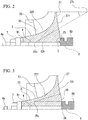
- FIG. 2 is a cross-sectional view showing a shape of a rear surface 22r of the disc 22 of the compressor wheel 3.
- the disc 22 has the rear surface 22r on the second side in the central axis C direction.
- the rear surface 22r has a convex curved surface 25 which is convex toward the second side (the right side in FIGS. 1 and 2 ) in the central axis C in at least part thereof including the center portion of the disc 22.
- the convex curved surface 25 is formed on the rear surface 22r with a constant curvature radius centering on a position 25c offset to the disc surface 22f side on the first side (the right side in FIG. 2 ) in the central axis C direction.
- a concave curved surface 27 which is concave toward the second side (the right side in FIG. 2 ) in the central axis C direction is continuously formed on a radially outer side of the convex curved surface 25.
- the concave curved surface 27 is formed on the rear surface 22r with a constant curvature radius centering on a position 27c offset to the turbine T (refer to FIG. 1 ) side.
- Such a compressor wheel 3 is provided so that the convex curved surface 25 of the rear surface 22r collides with the thrust collar 50.
- the convex curved surface 25 is formed at least in the center portion of the rear surface 22r of the disc 22 of the compressor wheel 3, it is possible to secure a large radial thickness T of the disc 22 at a portion on which the convex curved surface 25 is formed. Thus, strength of the disc 22 can be enhanced.
- the convex curved surface 25 can reduce a contact area with the thrust collar 50 which collides with the rear surface 22r of the disc 22, and thus local stress concentration at a contact portion with the thrust collar 50 can be prevented.
- the thickness of an outer circumferential portion of the disc 22 in the central axis C direction can be minimized by forming the concave curved surface 27 on an outer circumferential side of the convex curved surface 25, and a mass of the outer circumferential portion of the disc 22 can be minimized. Accordingly, it is possible to minimize centrifugal stress due to a weight of the disc 22.
- the rear surface 22r of the disc 22 has the convex curved surface 25 formed at the center portion thereof and the concave curved surface 27 formed at the outer circumferential side.
- the present invention is not limited to such a constitution.
- FIG. 3 is a cross-sectional view showing a first modified example of the shape of the rear surface of the disc of the compressor wheel.
- a contact plane 24 which is in contact with the thrust collar 50 is formed in the center portion of the rear surface 22r of the c 22.
- the contact plane 24 is a plane orthogonal to the central axis C.
- a convex curved surface 25 which is convex toward the second side (the right side in FIG. 4 ) in the central axis C direction is provided on an outer side of the contact plane 24 in the radial direction.
- a concave curved surface 27 which is convex toward the first side (the right side in FIG. 3 ) in the central axis C direction is continuously formed on an outer side of the convex curved surface 25 in the radial direction.
- the stress concentration on the rear surface 22r of the disc 22 can be reduced, and the reliability of the compressor wheel 3 can be enhanced.
- FIG. 4 is a cross-sectional view showing a second modified example of the shape of the rear surface of the disc of the compressor wheel.
- the rear surface 22r of the disc 22 has a convex curved surface 25 which is convex toward the second side (the right side in FIGS. 1 and 2 ) in the central axis C direction at the center portion of the disc 22.
- the rear surface 22r has an outer circumferential convex curved surface 26 which is continuous with an outer side of the convex curved surface 25 in the radial direction, is convex toward the second side (the right side in FIG. 4 ) in the central axis C direction and is formed with a curvature different from that of the convex curved surface 25.
- a concave curved surface 27 which is concave toward the second side (the right side in FIG. 4 ) in the central axis C direction is continuously formed on the outer side of the outer circumferential convex curved surface 26 in the radial direction.
- the stress concentration on the rear surface 22r of the disc 22 can be reduced, and the reliability of the compressor wheel 3 can be enhanced.
- FIG. 5 is a cross-sectional view showing a third modified example of the shape of the rear surface of the disc of the compressor wheel.
- the rear surface 22r of the disc 22 has a convex curved surface 25 which is convex toward the second side (the right side in FIG. 5 ) in the central axis C direction at the center portion of the disc 22.
- a tapered surface 29 which extends continuously from an outer circumferential end 25s of the convex curved surface 25 in a tangential direction is formed on an outer side of the convex curved surface 25 in the radial direction.
- a concave curved surface 27 which is concave toward the second side (the right side in FIG. 5 ) in the central axis C direction is continuously formed on the outer side of the tapered surface 29 in the radial direction.
- the stress concentration on the rear surface 22r of the disc 22 can be reduced, and the reliability of the compressor wheel 3 can be enhanced.
- the shape of the rear surface 22r of the disc 22 may be formed in shapes other than those exemplified in each of the above embodiment and modified examples.
- the convex curved surface 25 can be formed not only with a constant curvature but also with a free curve, for example.
- an open type impeller has been described as an example.
- the impeller is not limited to the open type impeller and may be a closed type impeller integrally including a cover portion, for example.
- turbocharger 1 was illustrated as the rotary machine.
- the rotary machine including the impeller is not limited to the turbocharger and may be a centrifugal compressor or the like, for example.
- the present invention is also applicable to an electric compressor without a turbine.
- the present invention can be applied to an impeller, a rotary machine, and a turbocharger. According to the present invention, it is possible to reduce the stress on the rear surface of the disc and to improve the reliability.
Landscapes
- Engineering & Computer Science (AREA)
- General Engineering & Computer Science (AREA)
- Mechanical Engineering (AREA)
- Life Sciences & Earth Sciences (AREA)
- Sustainable Development (AREA)
- Sustainable Energy (AREA)
- Chemical & Material Sciences (AREA)
- Combustion & Propulsion (AREA)
- Physics & Mathematics (AREA)
- Fluid Mechanics (AREA)
- Geometry (AREA)
- Structures Of Non-Positive Displacement Pumps (AREA)
- Supercharger (AREA)
Abstract
Description
- The present invention relates to an impeller, a rotary machine, and a turbocharger.
- A compressor wheel of a turbocharger often integrally includes a disc fixed to a rotating shaft, and a plurality of blades provided on a surface of the disc on one side in a central axis direction of the rotating shaft. In such a turbocharger, a rotation speed of the compressor wheel is also increased as performance thereof is improved.
- When the compressor wheel rotates, centrifugal stress due to a weight of the disc acts. In order to reduce the centrifugal stress, it has been performed to make an inner circumferential side of the disc thicker in the central axis direction in order to secure rigidity while minimizing a mass of an outer circumferential portion of the disc by making an outer circumferential side of the disc thinner in the central axis direction.
- For example, Patent Document 1 discloses a configuration which reduces the centrifugal stress of the disc by providing a taper on a rear surface of the outer circumferential portion of the disc in the radial direction (on a side opposite to the surface on which the blades are provided).
-
- [Patent Document 1]
Japanese Unexamined Patent Application, First Publication No.H11-270491 - However, as the rotation speed of the compressor wheel is increased, the influence of the stress acting on the disc is increased. For example, when a member such as a collar is provided on a rear surface of the compressor wheel to position the compressor wheel in the central axis direction, stress may occur on the rear surface of the compressor wheel due to contact with this member. On the other hand, when the disc is unnecessarily thickened in the central axis direction to increase strength, the influence of the centrifugal stress as described above increases.
- An object of the present invention is to provide an impeller, a rotary machine, and a turbocharger capable of reducing stress on a rear surface of a disc and improving reliability.
- According to a first aspect of the present invention, an impeller includes a disc formed in a disc shape and provided to be rotatable around a central axis, and a plurality of blades provided on a disc surface facing a first side in a central axis direction at intervals in a circumferential direction around the central axis. A rear surface of the disc facing a second side in the central axis direction has a convex curved surface which is convex toward the second side in the central axis direction at at least a part of a center portion of the disc.
- According to such a configuration, when the convex curved surface is formed at at least the center portion of the rear surface of the disc of the impeller, a large thickness of the disc in the radial direction can be ensured at the portion on which the convex curved surface is formed. Therefore, strength of the disc can be enhanced.
- Further, when other components collide with the rear surface of the disc, it is possible to reduce a contact area with other components and to prevent local stress concentration at portions in contact with other components.
- According to a second aspect of the present invention, in the first aspect, an outer circumferential convex curved surface which is convex toward the second side in the central axis direction and is formed with a curvature different from that of the convex curved surface may be continuously formed on an outer side of the convex curved surface in a radial direction.
- In this way, the thickness of the outer circumferential portion of the disc in the central axis direction is minimized by continuously forming the outer circumferential convex curved surface on the outer side of the convex curved surface in the radial direction, and a mass of the outer circumferential portion of the disc is minimized. Therefore, it is possible to minimize centrifugal stress due to a weight of the disc.
- According to a third aspect of the present invention, in the first aspect, a concave curved surface which is concave toward the second side in the central axial direction may be continuously formed on an outer side of the convex curved surface in a radial direction.
- In this way, a thickness of the outer circumferential portion of the disk in the central axis direction is minimized, and the mass of the outer circumferential portion of the disk is minimized. As a result, it is possible to minimize the centrifugal stress due to the weight of the disc.
- According to a fourth aspect of the present invention, in the first aspect, a tapered surface which extends in a tangential direction continuously with an outer circumferential end of the convex curved surface may be formed on an outer side of the convex curved surface in a radial direction.
- In this way, the thickness of the outer circumferential portion of the disk in the central axis direction is minimized, and the mass of the outer circumferential portion of the disk is minimized. As a result, it is possible to minimize the centrifugal stress due to the weight of the disc.
- According to a fifth aspect of the present invention, a rotary machine includes a rotating shaft which extends along a central axis, an impeller according to any one of the first to fourth aspects which is provided on the rotating shaft, and a collar which is provided on the rotating shaft and collides with the convex curved surface of the rear surface of the impeller.
- According to such a configuration, when the convex curved surface is formed at at least the center portion of the rear surface of the disc of the impeller, a large thickness of the disc in the radial direction can be ensured at the portion on which the convex curved surface is formed. Therefore, the strength of the disc can be enhanced.
- Further, it is possible to reduce a contact area with the collar colliding with the rear surface of the disc and to prevent the local stress concentration at a contact portion with the collar.
- According to a sixth aspect of the present invention, a turbocharger includes a rotating shaft which extends along a central axis, a turbine wheel provided on a first end side of the rotating shaft, and a compressor wheel provided on a second end side of the rotating shaft, the compressor wheel configured with the impeller according to the first to fourth aspects.
- Therefore, when the convex curved surface is formed at at least the center portion of the rear surface of the disc of the impeller forming a compressor wheel, a large thickness of the disc in the radial direction can be ensured at the portion on which the convex curved surface is formed. Thus, the strength of the disc can be enhanced.
- According to a seventh aspect of the present invention, the turbocharger may further include a collar which is provided on the rotating shaft and collides with the convex curved surface of the rear surface of the impeller.
- Therefore, it is possible to reduce the contact area with the collar colliding with the rear surface of the disc and to prevent the local stress concentration at the contact portion with the collar.
- According to the above-described impeller, rotary machine and turbocharger, it is possible to reduce stress on a rear surface of a disc and improve reliability.
-
-
FIG. 1 is a cross-sectional view of a turbocharger in an embodiment of the present invention. -
FIG. 2 is a cross-sectional view showing a shape of a rear surface of a disc of a compressor wheel provided in the turbocharger. -
FIG. 3 is a cross-sectional view showing a first modified example of the shape of the rear surface of the disc of the compressor wheel. -
FIG. 4 is a cross-sectional view showing a second modified example of the shape of the rear surface of the disc of the compressor wheel. -
FIG. 5 is a cross-sectional view showing a third modified example of the shape of the rear surface of the disc of the compressor wheel. - An impeller, a rotary machine and a turbocharger according to an embodiment of the present invention will be described with reference to the drawings.
-
FIG. 1 is a cross-sectional view of a turbocharger in an embodiment of the present invention. - As shown in
FIG. 1 , a turbocharger (a rotary machine) 1 includes aturbine wheel 2, a compressor wheel (an impeller) 3, a rotatingshaft 4,bearings shaft 4 extends in a horizontal direction. Here, the alternate long and short dash line shown inFIG. 1 indicates a central axis C of the rotatingshaft 4. - The bearing housing 6 is supported by a vehicle body or the like via a bracket (not shown), a compressor P, a turbine T, and so on. The bearing housing 6 has an opening 60b on one end side thereof and an opening 60a on the other end side thereof. The rotating
shaft 4 is supported by thebearings first end 4a and asecond end 4b of the rotatingshaft 4 protrude to the outside of the bearing housing 6 through theopenings 60a and 60b. That is, a part of the rotatingshaft 4 in a longitudinal direction along the central axis C is accommodated in the bearing housing 6. - The turbine T is provided on the
second end 4b side of the bearing housing 6. The turbine T includes aturbine wheel 2 and aturbine housing 31 which accommodates theturbine wheel 2. - The
turbine wheel 2 is provided integrally with thesecond end 4b of the rotatingshaft 4 and rotates around the central axis C integrally with the rotatingshaft 4. Theturbine wheel 2 has a plurality ofturbine blades 2w in a circumferential direction. - The
turbine housing 31 is mounted on one end side of the bearing housing 6 via amounting fixture 32. Theturbine housing 31 has an opening 31a at a position facing the bearing housing 6. Theturbine wheel 2 is accommodated in the opening 31a. - The
turbine housing 31 includes a gas introduction portion (not shown), ascroll flow path 34, and anexhaust portion 35. - The gas introduction portion (not shown) delivers some of exhaust gas discharged from the engine (not shown) into the
turbine housing 31. - The
scroll flow path 34 is continuously formed in the circumferential direction to be connected to the gas introduction portion (not shown) and to surround an outer circumferential side of theturbine wheel 2. Thescroll flow path 34 is provided so that at least part thereof in the circumferential direction communicates with an outer circumferential portion of theturbine wheel 2 and forms a flow path through which the exhaust gas for rotationally driving theturbine wheel 2 flows. - The exhaust gas flowing in from the gas introduction portion 33 flows on the outer circumferential side of the
turbine wheel 2 along thescroll flow path 34 in the circumferential direction. The exhaust gas flowing in the circumferential direction in this way strikes theturbine blades 2w of theturbine wheel 2, and thus theturbine wheel 2 is rotationally driven. Further, as the exhaust gas strikes theturbine blades 2w on the outer circumferential side of theturbine wheel 2, a direction of a flow thereof is changed. The exhaust gas of which the direction of the flow is changed by theturbine blades 2w is discharged from an inner circumferential side of theturbine wheel 2 into theexhaust portion 35. - The compressor P is provided on the
first end 4a side of the bearing housing 6. The compressor P includes acompressor wheel 3 and acompressor casing 10. - The
compressor wheel 3 includes adisc 22 and ablade 23. - The
disc 22 has a disc shape extending outward in a radial direction, and aninsertion hole 22h through which therotating shaft 4 is inserted is formed in a center portion thereof. Thedisc 22 has a predetermined length in the central axis C direction and is fixed to thefirst end 4a of therotating shaft 4. Thedisc 22 has a disc surface (surface) 22f on a first side (a left side inFIG. 1 ) in the central axis C direction. Thedisc surface 22f is formed by a curved surface which is gradually directed outward in the radial direction from a wheel inlet flow path 11 side on the first side in the central axis C direction to the bearing housing 6 side on the second side in the central axis C direction. - A plurality of
blades 23 are provided on thedisc surface 22f at intervals in the circumferential direction around the central axis C. - A thrust collar (collar) 50 is provided on the bearing housing 6 side of the
compressor wheel 3. Thethrust collar 50 has a cylindrical shape, and therotating shaft 4 is inserted therethrough. As thethrust collar 50 collides with a steppedportion 4d formed on therotating shaft 4 via anannular spacer 51, movement thereof toward theturbine wheel 2 in the central axis C direction is restricted. - As a
nut 7 is screwed onto a threadedportion 4n formed at thefirst end 4a of therotating shaft 4, thecompressor wheel 3 being sandwiched between thethrust collar 50 and thenut 7 and coupled to therotating shaft 4. - When the
turbine wheel 2 rotates, such acompressor wheel 3 rotates around the central axis C integrally with therotating shaft 4. Thecompressor wheel 3 raises a pressure and a temperature of air (intake air) with theblades 23 and delivers it outward in the radial direction. - The
compressor casing 10 forms the wheel inlet flow path 11, a wheel flow path 12, adiffuser 13, and ascroll 14. - For example, the wheel inlet flow path 11 is formed between an intake pipe (not shown) extending from an air cleaner box or the like and the wheel flow path 12.
- The wheel flow path 12 is formed by a space for accommodating the
compressor wheel 3. This wheel flow path 12 forms a flow path, through which compressed air flows, between the wheel flow path 12 and thedisc 22 of thecompressor wheel 3. - The
diffuser 13 extends outward from an outermostcircumferential portion 12a of the wheel flow path 12 in the radial direction centering on the central axis C. Thediffuser 13 converts, for example, kinetic energy of the air compressed by thecompressor wheel 3 into pressure energy. Thediffuser 13 connects the wheel inlet flow path 11 with thescroll 14. - The
scroll 14 further converts the kinetic energy of the air flowing in from thediffuser 13 into the pressure energy and discharges it to the outside of thecompressor casing 10. The air discharged through thescroll 14 is supplied to a cylinder or the like of an engine (not shown). Thescroll 14 extends in the circumferential direction centering on the central axis C. A cross-sectional area of thescroll 14 thus formed gradually enlarges toward an outlet port (not shown) of the compressor P. -
FIG. 2 is a cross-sectional view showing a shape of arear surface 22r of thedisc 22 of thecompressor wheel 3. - As shown in
FIG. 2 , thedisc 22 has therear surface 22r on the second side in the central axis C direction. Therear surface 22r has a convexcurved surface 25 which is convex toward the second side (the right side inFIGS. 1 and2 ) in the central axis C in at least part thereof including the center portion of thedisc 22. The convexcurved surface 25 is formed on therear surface 22r with a constant curvature radius centering on aposition 25c offset to thedisc surface 22f side on the first side (the right side inFIG. 2 ) in the central axis C direction. - Further, on the
rear surface 22r, a concavecurved surface 27 which is concave toward the second side (the right side inFIG. 2 ) in the central axis C direction is continuously formed on a radially outer side of the convexcurved surface 25. The concavecurved surface 27 is formed on therear surface 22r with a constant curvature radius centering on aposition 27c offset to the turbine T (refer toFIG. 1 ) side. - Such a
compressor wheel 3 is provided so that the convexcurved surface 25 of therear surface 22r collides with thethrust collar 50. - According to the
compressor wheel 3 and the turbocharger 1 of the above-described embodiment, when the convexcurved surface 25 is formed at least in the center portion of therear surface 22r of thedisc 22 of thecompressor wheel 3, it is possible to secure a large radial thickness T of thedisc 22 at a portion on which the convexcurved surface 25 is formed. Thus, strength of thedisc 22 can be enhanced. - Further, the convex
curved surface 25 can reduce a contact area with thethrust collar 50 which collides with therear surface 22r of thedisc 22, and thus local stress concentration at a contact portion with thethrust collar 50 can be prevented. - Also, the thickness of an outer circumferential portion of the
disc 22 in the central axis C direction can be minimized by forming the concavecurved surface 27 on an outer circumferential side of the convexcurved surface 25, and a mass of the outer circumferential portion of thedisc 22 can be minimized. Accordingly, it is possible to minimize centrifugal stress due to a weight of thedisc 22. - In this way, it is possible to reduce the stress concentration on the
rear surface 22r of thedisc 22 and to improve reliability of thecompressor wheel 3. - In the above-described first embodiment, the
rear surface 22r of thedisc 22 has the convexcurved surface 25 formed at the center portion thereof and the concavecurved surface 27 formed at the outer circumferential side. However, the present invention is not limited to such a constitution. - Hereinafter, a plurality of modified examples of the shape of the
rear surface 22r of thedisc 22 will be described. -
FIG. 3 is a cross-sectional view showing a first modified example of the shape of the rear surface of the disc of the compressor wheel. - As shown in
FIG. 3 , acontact plane 24 which is in contact with thethrust collar 50 is formed in the center portion of therear surface 22r of thec 22. Thecontact plane 24 is a plane orthogonal to the central axis C. - On the
rear surface 22r of thedisc 22, a convexcurved surface 25 which is convex toward the second side (the right side inFIG. 4 ) in the central axis C direction is provided on an outer side of thecontact plane 24 in the radial direction. - Further, on the
rear surface 22r, a concavecurved surface 27 which is convex toward the first side (the right side inFIG. 3 ) in the central axis C direction is continuously formed on an outer side of the convexcurved surface 25 in the radial direction. - With such a configuration as well, the stress concentration on the
rear surface 22r of thedisc 22 can be reduced, and the reliability of thecompressor wheel 3 can be enhanced. -
FIG. 4 is a cross-sectional view showing a second modified example of the shape of the rear surface of the disc of the compressor wheel. - As shown in
FIG. 4 , therear surface 22r of thedisc 22 has a convexcurved surface 25 which is convex toward the second side (the right side inFIGS. 1 and2 ) in the central axis C direction at the center portion of thedisc 22. - Further, the
rear surface 22r has an outer circumferential convexcurved surface 26 which is continuous with an outer side of the convexcurved surface 25 in the radial direction, is convex toward the second side (the right side inFIG. 4 ) in the central axis C direction and is formed with a curvature different from that of the convexcurved surface 25. - Furthermore, on the
rear surface 22r, a concavecurved surface 27 which is concave toward the second side (the right side inFIG. 4 ) in the central axis C direction is continuously formed on the outer side of the outer circumferential convexcurved surface 26 in the radial direction. - With such a configuration as well, the stress concentration on the
rear surface 22r of thedisc 22 can be reduced, and the reliability of thecompressor wheel 3 can be enhanced. -
FIG. 5 is a cross-sectional view showing a third modified example of the shape of the rear surface of the disc of the compressor wheel. - As shown in
FIG. 5 , therear surface 22r of thedisc 22 has a convexcurved surface 25 which is convex toward the second side (the right side inFIG. 5 ) in the central axis C direction at the center portion of thedisc 22. - Also, on the
rear surface 22r, atapered surface 29 which extends continuously from an outercircumferential end 25s of the convexcurved surface 25 in a tangential direction is formed on an outer side of the convexcurved surface 25 in the radial direction. - Furthermore, on the
rear surface 22r, a concavecurved surface 27 which is concave toward the second side (the right side inFIG. 5 ) in the central axis C direction is continuously formed on the outer side of the taperedsurface 29 in the radial direction. - With such a configuration as well, the stress concentration on the
rear surface 22r of thedisc 22 can be reduced, and the reliability of thecompressor wheel 3 can be enhanced. - The present invention is not limited to the above-described embodiment, and the design can be changed without departing from the scope of the present invention.
- For example, the shape of the
rear surface 22r of thedisc 22 may be formed in shapes other than those exemplified in each of the above embodiment and modified examples. For example, the convexcurved surface 25 can be formed not only with a constant curvature but also with a free curve, for example. - Further, for the shape of the convex
curved surface 25 on the outer side of the center portion of therear surface 22r in the radial direction, it is possible to have shapes other than those exemplified in each of the above embodiment and modified examples. - Further, for example, in the above-described embodiment, an open type impeller has been described as an example. However, the impeller is not limited to the open type impeller and may be a closed type impeller integrally including a cover portion, for example.
- In addition, the turbocharger 1 was illustrated as the rotary machine. However, the rotary machine including the impeller is not limited to the turbocharger and may be a centrifugal compressor or the like, for example. Also, the present invention is also applicable to an electric compressor without a turbine.
- The present invention can be applied to an impeller, a rotary machine, and a turbocharger. According to the present invention, it is possible to reduce the stress on the rear surface of the disc and to improve the reliability.
-
- 1
- Turbocharger (rotary machine)
- 2
- Turbine wheel
- 2w
- Turbine blade
- 3
- Compressor wheel (impeller)
- 4
- Rotating shaft
- 4a
- First end
- 4b
- Second end
- 4d
- Stepped portion
- 4n
- Threaded portion
- 5A, 5B
- Bearing
- 6
- Bearing housing
- 7
- Nut
- 10
- Compressor casing
- 11
- Wheel inlet flow path
- 12
- Wheel flow path
- 12a
- Outermost circumferential portion
- 13
- Diffuser
- 14
- Scroll
- 16
- Bearing housing
- 22
- Disc
- 22f
- Disc surface (surface)
- 22h
- Insertion hole
- 22r
- Rear surface
- 23
- Blade
- 24
- Contact plane
- 25
- Convex curved surface
- 25c
- Position
- 25s
- Outer circumferential end
- 26
- Outer circumferential convex curved surface
- 27
- Concave curved surface
- 27c
- Position
- 29
- Tapered surface
- 31
- Turbine housing
- 31a
- Opening
- 32
- Mounting fixture
- 33
- Gas introduction portion
- 34
- Scroll flow path
- 35
- Exhaust portion
- 50
- Thrust collar (collar)
- 51
- Spacer
- 60a, 60b
- Opening
- C
- Central axis
- P
- Compressor
- T
- Turbine
Claims (7)
- An impeller comprising:a disc formed in a disc shape and provided to be rotatable around a central axis; anda plurality of blades provided on a disc surface facing a first side in a central axis direction at intervals in a circumferential direction around the central axis,wherein a rear surface of the disc facing a second side in the central axis direction has a convex curved surface which is convex toward the second side in the central axis direction at at least part of a center portion of the disc.
- The impeller according to claim 1, wherein an outer circumferential convex curved surface which is convex toward the second side in the central axis direction and is formed with a curvature different from that of the convex curved surface is continuously formed on an outer side of the convex curved surface in a radial direction.
- The impeller according to claim 1, wherein a concave curved surface which is concave toward the second side in the central axial direction is continuously formed on an outer side of the convex curved surface in a radial direction.
- The impeller according to claim 1, wherein a tapered surface which extends in a tangential direction continuously with an outer circumferential end of the convex curved surface is formed on an outer side of the convex curved surface in a radial direction.
- A rotary machine comprising:a rotating shaft which extends along a central axis;an impeller according to any one of claims 1 to 4 which is provided on the rotating shaft; anda collar which is provided on the rotating shaft and collides with the convex curved surface of the rear surface of the impeller.
- A turbocharger comprising:a rotating shaft which extends along a central axis;a turbine wheel provided on a first end side of the rotating shaft; anda compressor wheel provided on a second end side of the rotating shaft, the compressor wheel configured with the impeller according to any one of claims 1 to 4.
- The turbocharger according to claim 6, further comprising a collar which is provided on the rotating shaft and collides with the convex curved surface of the rear surface of the impeller.
Applications Claiming Priority (1)
| Application Number | Priority Date | Filing Date | Title |
|---|---|---|---|
| PCT/JP2016/060456 WO2017168642A1 (en) | 2016-03-30 | 2016-03-30 | Impeller, rotary machine, and turbocharger |
Publications (3)
| Publication Number | Publication Date |
|---|---|
| EP3434908A1 true EP3434908A1 (en) | 2019-01-30 |
| EP3434908A4 EP3434908A4 (en) | 2019-04-03 |
| EP3434908B1 EP3434908B1 (en) | 2020-10-07 |
Family
ID=59963736
Family Applications (1)
| Application Number | Title | Priority Date | Filing Date |
|---|---|---|---|
| EP16896861.8A Not-in-force EP3434908B1 (en) | 2016-03-30 | 2016-03-30 | Impeller, rotary machine, and turbocharger |
Country Status (5)
| Country | Link |
|---|---|
| US (1) | US10883513B2 (en) |
| EP (1) | EP3434908B1 (en) |
| JP (1) | JP6745331B2 (en) |
| CN (1) | CN109196230B (en) |
| WO (1) | WO2017168642A1 (en) |
Cited By (1)
| Publication number | Priority date | Publication date | Assignee | Title |
|---|---|---|---|---|
| EP3835593A1 (en) * | 2019-12-10 | 2021-06-16 | Ingersoll-Rand Industrial U.S., Inc. | Centrifugal compressor impeller with nonlinear backwall |
Families Citing this family (1)
| Publication number | Priority date | Publication date | Assignee | Title |
|---|---|---|---|---|
| US12392347B1 (en) | 2024-02-16 | 2025-08-19 | Pratt & Whitney Canada Corp. | Centrifugal compressor impeller and method of producing the same |
Family Cites Families (19)
| Publication number | Priority date | Publication date | Assignee | Title |
|---|---|---|---|---|
| JPS55119395U (en) * | 1979-02-16 | 1980-08-23 | ||
| IT1239829B (en) * | 1990-02-13 | 1993-11-15 | Renzo Ghiotto | DIFFERENTIATED THICKNESS PUMP BODY |
| JP2676450B2 (en) * | 1991-01-11 | 1997-11-17 | 株式会社荏原製作所 | Sheet metal pump casing |
| JPH11270491A (en) | 1998-03-20 | 1999-10-05 | Ishikawajima Harima Heavy Ind Co Ltd | Disc structure of impeller in centrifugal compressor |
| JP2002047944A (en) | 2000-07-31 | 2002-02-15 | Toyota Motor Corp | High-speed impeller |
| JP4554189B2 (en) * | 2003-11-26 | 2010-09-29 | 株式会社エンプラス | Centrifugal impeller |
| GB0425088D0 (en) * | 2004-11-13 | 2004-12-15 | Holset Engineering Co | Compressor wheel |
| JP2008163760A (en) * | 2006-12-27 | 2008-07-17 | Ihi Corp | Radial impeller and supercharger |
| US20080229742A1 (en) * | 2007-03-21 | 2008-09-25 | Philippe Renaud | Extended Leading-Edge Compressor Wheel |
| FR2931214B1 (en) * | 2008-05-15 | 2013-07-26 | Turbomeca | COMPRESSOR WHEEL BLADE WITH EVOLVING CONNECTION |
| JP5504867B2 (en) | 2009-12-11 | 2014-05-28 | 株式会社Ihi | Impeller mounting structure and turbocharger |
| CN201610860U (en) * | 2010-02-02 | 2010-10-20 | 高密市天缘精密机械制造有限公司 | Compressor impeller of turbocharger |
| CN103362860A (en) * | 2012-04-02 | 2013-10-23 | 珠海格力电器股份有限公司 | High-speed fluid dynamic machine, and rotor forming method and assembling method thereof |
| DE102012022647A1 (en) * | 2012-11-20 | 2014-05-22 | Daimler Ag | Exhaust gas turbocharger for lifting cylinder internal combustion engine of motor vehicle, has portion limited by spine in axial direction, where spine comprises blade elements partially arranged in portion for compressing blade |
| JP5606515B2 (en) * | 2012-12-13 | 2014-10-15 | 三菱重工業株式会社 | Compressor |
| US10125793B2 (en) * | 2013-02-22 | 2018-11-13 | Mitsubishi Heavy Industries, Ltd. | Centrifugal compressor |
| EP3112692B1 (en) | 2014-02-26 | 2018-08-29 | Mitsubishi Heavy Industries, Ltd. | Centrifugal compressor, turbocharger with said centrifugal compressor, and method for manufacturing said centrifugal compressor |
| CN204312393U (en) * | 2014-11-13 | 2015-05-06 | 湖南天雁机械有限责任公司 | With the turbosupercharger of gas compressor arc diagonal impeller |
| CN204312394U (en) * | 2014-11-13 | 2015-05-06 | 湖南天雁机械有限责任公司 | With the turbosupercharger of diagonal impeller of compressor |
-
2016
- 2016-03-30 WO PCT/JP2016/060456 patent/WO2017168642A1/en not_active Ceased
- 2016-03-30 CN CN201680086154.4A patent/CN109196230B/en not_active Expired - Fee Related
- 2016-03-30 US US16/088,558 patent/US10883513B2/en not_active Expired - Fee Related
- 2016-03-30 EP EP16896861.8A patent/EP3434908B1/en not_active Not-in-force
- 2016-03-30 JP JP2018507945A patent/JP6745331B2/en not_active Expired - Fee Related
Cited By (5)
| Publication number | Priority date | Publication date | Assignee | Title |
|---|---|---|---|---|
| EP3835593A1 (en) * | 2019-12-10 | 2021-06-16 | Ingersoll-Rand Industrial U.S., Inc. | Centrifugal compressor impeller with nonlinear backwall |
| US11408434B2 (en) | 2019-12-10 | 2022-08-09 | Ingersoll-Rand Industrial U.S., Inc. | Centrifugal compressor impeller with nonlinear backwall |
| US11821434B2 (en) | 2019-12-10 | 2023-11-21 | Ingersoll-Rand Industrial U.S., Inc. | Centrifugal compressor impeller with nonlinear backwall |
| US12110902B2 (en) | 2019-12-10 | 2024-10-08 | Ingersoll-Rand Industrial U.S., Inc. | Centrifugal compressor impeller with nonlinear backwall |
| US12612923B1 (en) | 2019-12-10 | 2026-04-28 | Ingersoll-Rand Industrial U.S., Inc. | Centrifugal compressor impeller with nonlinear backwall |
Also Published As
| Publication number | Publication date |
|---|---|
| WO2017168642A1 (en) | 2017-10-05 |
| US20190113048A1 (en) | 2019-04-18 |
| CN109196230B (en) | 2021-07-30 |
| EP3434908B1 (en) | 2020-10-07 |
| US10883513B2 (en) | 2021-01-05 |
| EP3434908A4 (en) | 2019-04-03 |
| JP6745331B2 (en) | 2020-08-26 |
| JPWO2017168642A1 (en) | 2019-02-14 |
| CN109196230A (en) | 2019-01-11 |
Similar Documents
| Publication | Publication Date | Title |
|---|---|---|
| EP3249192B1 (en) | Bearing device for turbocharger, and turbocharger | |
| US8251650B2 (en) | Compressor housing | |
| EP2703620A1 (en) | Turbine housing for turbocharger | |
| US9810225B2 (en) | Turbine for turbocharger and method for assembling turbocharger | |
| US10851792B2 (en) | Diagonal fan | |
| US11261746B2 (en) | Turbine and turbocharger | |
| EP3258080B1 (en) | Supercharger | |
| EP3144541B1 (en) | Compressor | |
| US9903379B2 (en) | Variable nozzle unit and variable geometry system turbocharger | |
| US20180073520A1 (en) | Charging device | |
| US10883513B2 (en) | Impeller, rotary machine, and turbocharger | |
| EP3421811A1 (en) | Compressor impeller and turbocharger | |
| EP3073091B1 (en) | Compressor | |
| US11359642B2 (en) | Electric compressor | |
| EP3382209B1 (en) | Centrifugal compressor and supercharger | |
| EP3686439B1 (en) | Multi-stage centrifugal compressor | |
| KR20190032554A (en) | Rotating machine, Exhaust member of rotating machine | |
| WO2022107519A1 (en) | Centrifugal compressor and supercharger | |
| CN113944653A (en) | Centrifugal compressor | |
| EP3163090B1 (en) | Centrifugal compressor and supercharger with same | |
| EP3705695A1 (en) | Diffuser and turbocharger | |
| JP2020051392A (en) | Bearing structure of exhaust turbo supercharger |
Legal Events
| Date | Code | Title | Description |
|---|---|---|---|
| STAA | Information on the status of an ep patent application or granted ep patent |
Free format text: STATUS: THE INTERNATIONAL PUBLICATION HAS BEEN MADE |
|
| PUAI | Public reference made under article 153(3) epc to a published international application that has entered the european phase |
Free format text: ORIGINAL CODE: 0009012 |
|
| STAA | Information on the status of an ep patent application or granted ep patent |
Free format text: STATUS: REQUEST FOR EXAMINATION WAS MADE |
|
| 17P | Request for examination filed |
Effective date: 20181023 |
|
| AK | Designated contracting states |
Kind code of ref document: A1 Designated state(s): AL AT BE BG CH CY CZ DE DK EE ES FI FR GB GR HR HU IE IS IT LI LT LU LV MC MK MT NL NO PL PT RO RS SE SI SK SM TR |
|
| AX | Request for extension of the european patent |
Extension state: BA ME |
|
| A4 | Supplementary search report drawn up and despatched |
Effective date: 20190227 |
|
| RIC1 | Information provided on ipc code assigned before grant |
Ipc: F04D 29/28 20060101AFI20190222BHEP Ipc: F04D 29/26 20060101ALI20190222BHEP |
|
| DAV | Request for validation of the european patent (deleted) | ||
| DAX | Request for extension of the european patent (deleted) | ||
| STAA | Information on the status of an ep patent application or granted ep patent |
Free format text: STATUS: EXAMINATION IS IN PROGRESS |
|
| 17Q | First examination report despatched |
Effective date: 20191114 |
|
| GRAP | Despatch of communication of intention to grant a patent |
Free format text: ORIGINAL CODE: EPIDOSNIGR1 |
|
| STAA | Information on the status of an ep patent application or granted ep patent |
Free format text: STATUS: GRANT OF PATENT IS INTENDED |
|
| INTG | Intention to grant announced |
Effective date: 20200519 |
|
| GRAS | Grant fee paid |
Free format text: ORIGINAL CODE: EPIDOSNIGR3 |
|
| GRAA | (expected) grant |
Free format text: ORIGINAL CODE: 0009210 |
|
| STAA | Information on the status of an ep patent application or granted ep patent |
Free format text: STATUS: THE PATENT HAS BEEN GRANTED |
|
| AK | Designated contracting states |
Kind code of ref document: B1 Designated state(s): AL AT BE BG CH CY CZ DE DK EE ES FI FR GB GR HR HU IE IS IT LI LT LU LV MC MK MT NL NO PL PT RO RS SE SI SK SM TR |
|
| REG | Reference to a national code |
Ref country code: GB Ref legal event code: FG4D |
|
| REG | Reference to a national code |
Ref country code: CH Ref legal event code: EP Ref country code: AT Ref legal event code: REF Ref document number: 1321435 Country of ref document: AT Kind code of ref document: T Effective date: 20201015 |
|
| REG | Reference to a national code |
Ref country code: DE Ref legal event code: R096 Ref document number: 602016045635 Country of ref document: DE |
|
| REG | Reference to a national code |
Ref country code: IE Ref legal event code: FG4D |
|
| REG | Reference to a national code |
Ref country code: NL Ref legal event code: FP |
|
| REG | Reference to a national code |
Ref country code: AT Ref legal event code: MK05 Ref document number: 1321435 Country of ref document: AT Kind code of ref document: T Effective date: 20201007 |
|
| PG25 | Lapsed in a contracting state [announced via postgrant information from national office to epo] |
Ref country code: FI Free format text: LAPSE BECAUSE OF FAILURE TO SUBMIT A TRANSLATION OF THE DESCRIPTION OR TO PAY THE FEE WITHIN THE PRESCRIBED TIME-LIMIT Effective date: 20201007 Ref country code: GR Free format text: LAPSE BECAUSE OF FAILURE TO SUBMIT A TRANSLATION OF THE DESCRIPTION OR TO PAY THE FEE WITHIN THE PRESCRIBED TIME-LIMIT Effective date: 20210108 Ref country code: NO Free format text: LAPSE BECAUSE OF FAILURE TO SUBMIT A TRANSLATION OF THE DESCRIPTION OR TO PAY THE FEE WITHIN THE PRESCRIBED TIME-LIMIT Effective date: 20210107 Ref country code: RS Free format text: LAPSE BECAUSE OF FAILURE TO SUBMIT A TRANSLATION OF THE DESCRIPTION OR TO PAY THE FEE WITHIN THE PRESCRIBED TIME-LIMIT Effective date: 20201007 Ref country code: PT Free format text: LAPSE BECAUSE OF FAILURE TO SUBMIT A TRANSLATION OF THE DESCRIPTION OR TO PAY THE FEE WITHIN THE PRESCRIBED TIME-LIMIT Effective date: 20210208 |
|
| PGFP | Annual fee paid to national office [announced via postgrant information from national office to epo] |
Ref country code: NL Payment date: 20210212 Year of fee payment: 6 Ref country code: FR Payment date: 20210210 Year of fee payment: 6 |
|
| REG | Reference to a national code |
Ref country code: LT Ref legal event code: MG4D |
|
| PG25 | Lapsed in a contracting state [announced via postgrant information from national office to epo] |
Ref country code: PL Free format text: LAPSE BECAUSE OF FAILURE TO SUBMIT A TRANSLATION OF THE DESCRIPTION OR TO PAY THE FEE WITHIN THE PRESCRIBED TIME-LIMIT Effective date: 20201007 Ref country code: IS Free format text: LAPSE BECAUSE OF FAILURE TO SUBMIT A TRANSLATION OF THE DESCRIPTION OR TO PAY THE FEE WITHIN THE PRESCRIBED TIME-LIMIT Effective date: 20210207 Ref country code: LV Free format text: LAPSE BECAUSE OF FAILURE TO SUBMIT A TRANSLATION OF THE DESCRIPTION OR TO PAY THE FEE WITHIN THE PRESCRIBED TIME-LIMIT Effective date: 20201007 Ref country code: BG Free format text: LAPSE BECAUSE OF FAILURE TO SUBMIT A TRANSLATION OF THE DESCRIPTION OR TO PAY THE FEE WITHIN THE PRESCRIBED TIME-LIMIT Effective date: 20210107 Ref country code: AT Free format text: LAPSE BECAUSE OF FAILURE TO SUBMIT A TRANSLATION OF THE DESCRIPTION OR TO PAY THE FEE WITHIN THE PRESCRIBED TIME-LIMIT Effective date: 20201007 Ref country code: ES Free format text: LAPSE BECAUSE OF FAILURE TO SUBMIT A TRANSLATION OF THE DESCRIPTION OR TO PAY THE FEE WITHIN THE PRESCRIBED TIME-LIMIT Effective date: 20201007 Ref country code: SE Free format text: LAPSE BECAUSE OF FAILURE TO SUBMIT A TRANSLATION OF THE DESCRIPTION OR TO PAY THE FEE WITHIN THE PRESCRIBED TIME-LIMIT Effective date: 20201007 |
|
| PGFP | Annual fee paid to national office [announced via postgrant information from national office to epo] |
Ref country code: GB Payment date: 20210318 Year of fee payment: 6 |
|
| PG25 | Lapsed in a contracting state [announced via postgrant information from national office to epo] |
Ref country code: HR Free format text: LAPSE BECAUSE OF FAILURE TO SUBMIT A TRANSLATION OF THE DESCRIPTION OR TO PAY THE FEE WITHIN THE PRESCRIBED TIME-LIMIT Effective date: 20201007 |
|
| REG | Reference to a national code |
Ref country code: DE Ref legal event code: R097 Ref document number: 602016045635 Country of ref document: DE |
|
| PG25 | Lapsed in a contracting state [announced via postgrant information from national office to epo] |
Ref country code: RO Free format text: LAPSE BECAUSE OF FAILURE TO SUBMIT A TRANSLATION OF THE DESCRIPTION OR TO PAY THE FEE WITHIN THE PRESCRIBED TIME-LIMIT Effective date: 20201007 Ref country code: SK Free format text: LAPSE BECAUSE OF FAILURE TO SUBMIT A TRANSLATION OF THE DESCRIPTION OR TO PAY THE FEE WITHIN THE PRESCRIBED TIME-LIMIT Effective date: 20201007 Ref country code: CZ Free format text: LAPSE BECAUSE OF FAILURE TO SUBMIT A TRANSLATION OF THE DESCRIPTION OR TO PAY THE FEE WITHIN THE PRESCRIBED TIME-LIMIT Effective date: 20201007 Ref country code: EE Free format text: LAPSE BECAUSE OF FAILURE TO SUBMIT A TRANSLATION OF THE DESCRIPTION OR TO PAY THE FEE WITHIN THE PRESCRIBED TIME-LIMIT Effective date: 20201007 Ref country code: LT Free format text: LAPSE BECAUSE OF FAILURE TO SUBMIT A TRANSLATION OF THE DESCRIPTION OR TO PAY THE FEE WITHIN THE PRESCRIBED TIME-LIMIT Effective date: 20201007 Ref country code: SM Free format text: LAPSE BECAUSE OF FAILURE TO SUBMIT A TRANSLATION OF THE DESCRIPTION OR TO PAY THE FEE WITHIN THE PRESCRIBED TIME-LIMIT Effective date: 20201007 |
|
| PLBE | No opposition filed within time limit |
Free format text: ORIGINAL CODE: 0009261 |
|
| STAA | Information on the status of an ep patent application or granted ep patent |
Free format text: STATUS: NO OPPOSITION FILED WITHIN TIME LIMIT |
|
| PG25 | Lapsed in a contracting state [announced via postgrant information from national office to epo] |
Ref country code: DK Free format text: LAPSE BECAUSE OF FAILURE TO SUBMIT A TRANSLATION OF THE DESCRIPTION OR TO PAY THE FEE WITHIN THE PRESCRIBED TIME-LIMIT Effective date: 20201007 |
|
| 26N | No opposition filed |
Effective date: 20210708 |
|
| PG25 | Lapsed in a contracting state [announced via postgrant information from national office to epo] |
Ref country code: AL Free format text: LAPSE BECAUSE OF FAILURE TO SUBMIT A TRANSLATION OF THE DESCRIPTION OR TO PAY THE FEE WITHIN THE PRESCRIBED TIME-LIMIT Effective date: 20201007 Ref country code: IT Free format text: LAPSE BECAUSE OF FAILURE TO SUBMIT A TRANSLATION OF THE DESCRIPTION OR TO PAY THE FEE WITHIN THE PRESCRIBED TIME-LIMIT Effective date: 20201007 Ref country code: MC Free format text: LAPSE BECAUSE OF FAILURE TO SUBMIT A TRANSLATION OF THE DESCRIPTION OR TO PAY THE FEE WITHIN THE PRESCRIBED TIME-LIMIT Effective date: 20201007 |
|
| REG | Reference to a national code |
Ref country code: CH Ref legal event code: PL |
|
| PG25 | Lapsed in a contracting state [announced via postgrant information from national office to epo] |
Ref country code: SI Free format text: LAPSE BECAUSE OF FAILURE TO SUBMIT A TRANSLATION OF THE DESCRIPTION OR TO PAY THE FEE WITHIN THE PRESCRIBED TIME-LIMIT Effective date: 20201007 |
|
| REG | Reference to a national code |
Ref country code: BE Ref legal event code: MM Effective date: 20210331 |
|
| PG25 | Lapsed in a contracting state [announced via postgrant information from national office to epo] |
Ref country code: CH Free format text: LAPSE BECAUSE OF NON-PAYMENT OF DUE FEES Effective date: 20210331 Ref country code: LI Free format text: LAPSE BECAUSE OF NON-PAYMENT OF DUE FEES Effective date: 20210331 Ref country code: LU Free format text: LAPSE BECAUSE OF NON-PAYMENT OF DUE FEES Effective date: 20210330 Ref country code: IE Free format text: LAPSE BECAUSE OF NON-PAYMENT OF DUE FEES Effective date: 20210330 |
|
| PG25 | Lapsed in a contracting state [announced via postgrant information from national office to epo] |
Ref country code: IS Free format text: LAPSE BECAUSE OF FAILURE TO SUBMIT A TRANSLATION OF THE DESCRIPTION OR TO PAY THE FEE WITHIN THE PRESCRIBED TIME-LIMIT Effective date: 20210207 |
|
| PG25 | Lapsed in a contracting state [announced via postgrant information from national office to epo] |
Ref country code: BE Free format text: LAPSE BECAUSE OF NON-PAYMENT OF DUE FEES Effective date: 20210331 |
|
| REG | Reference to a national code |
Ref country code: NL Ref legal event code: MM Effective date: 20220401 |
|
| GBPC | Gb: european patent ceased through non-payment of renewal fee |
Effective date: 20220330 |
|
| PG25 | Lapsed in a contracting state [announced via postgrant information from national office to epo] |
Ref country code: NL Free format text: LAPSE BECAUSE OF NON-PAYMENT OF DUE FEES Effective date: 20220401 Ref country code: GB Free format text: LAPSE BECAUSE OF NON-PAYMENT OF DUE FEES Effective date: 20220330 Ref country code: FR Free format text: LAPSE BECAUSE OF NON-PAYMENT OF DUE FEES Effective date: 20220331 |
|
| PGFP | Annual fee paid to national office [announced via postgrant information from national office to epo] |
Ref country code: DE Payment date: 20230131 Year of fee payment: 8 |
|
| PG25 | Lapsed in a contracting state [announced via postgrant information from national office to epo] |
Ref country code: CY Free format text: LAPSE BECAUSE OF FAILURE TO SUBMIT A TRANSLATION OF THE DESCRIPTION OR TO PAY THE FEE WITHIN THE PRESCRIBED TIME-LIMIT Effective date: 20201007 |
|
| PG25 | Lapsed in a contracting state [announced via postgrant information from national office to epo] |
Ref country code: HU Free format text: LAPSE BECAUSE OF FAILURE TO SUBMIT A TRANSLATION OF THE DESCRIPTION OR TO PAY THE FEE WITHIN THE PRESCRIBED TIME-LIMIT; INVALID AB INITIO Effective date: 20160330 |
|
| PG25 | Lapsed in a contracting state [announced via postgrant information from national office to epo] |
Ref country code: MK Free format text: LAPSE BECAUSE OF FAILURE TO SUBMIT A TRANSLATION OF THE DESCRIPTION OR TO PAY THE FEE WITHIN THE PRESCRIBED TIME-LIMIT Effective date: 20201007 |
|
| PG25 | Lapsed in a contracting state [announced via postgrant information from national office to epo] |
Ref country code: TR Free format text: LAPSE BECAUSE OF FAILURE TO SUBMIT A TRANSLATION OF THE DESCRIPTION OR TO PAY THE FEE WITHIN THE PRESCRIBED TIME-LIMIT Effective date: 20201007 |
|
| PG25 | Lapsed in a contracting state [announced via postgrant information from national office to epo] |
Ref country code: MT Free format text: LAPSE BECAUSE OF FAILURE TO SUBMIT A TRANSLATION OF THE DESCRIPTION OR TO PAY THE FEE WITHIN THE PRESCRIBED TIME-LIMIT Effective date: 20201007 |
|
| REG | Reference to a national code |
Ref country code: DE Ref legal event code: R119 Ref document number: 602016045635 Country of ref document: DE |
|
| PG25 | Lapsed in a contracting state [announced via postgrant information from national office to epo] |
Ref country code: DE Free format text: LAPSE BECAUSE OF NON-PAYMENT OF DUE FEES Effective date: 20241001 |
|
| PG25 | Lapsed in a contracting state [announced via postgrant information from national office to epo] |
Ref country code: DE Free format text: LAPSE BECAUSE OF NON-PAYMENT OF DUE FEES Effective date: 20241001 |