EP3434418B1 - Treiber für knochenschraube - Google Patents
Treiber für knochenschraube Download PDFInfo
- Publication number
- EP3434418B1 EP3434418B1 EP18196028.7A EP18196028A EP3434418B1 EP 3434418 B1 EP3434418 B1 EP 3434418B1 EP 18196028 A EP18196028 A EP 18196028A EP 3434418 B1 EP3434418 B1 EP 3434418B1
- Authority
- EP
- European Patent Office
- Prior art keywords
- housing
- motor
- driveshaft
- driver
- proximal end
- Prior art date
- Legal status (The legal status is an assumption and is not a legal conclusion. Google has not performed a legal analysis and makes no representation as to the accuracy of the status listed.)
- Active
Links
- 210000000988 bone and bone Anatomy 0.000 claims description 28
- 238000003780 insertion Methods 0.000 claims description 20
- 230000037431 insertion Effects 0.000 claims description 20
- 230000004913 activation Effects 0.000 claims description 16
- 238000006073 displacement reaction Methods 0.000 claims description 4
- 239000000853 adhesive Substances 0.000 claims description 2
- 230000001070 adhesive effect Effects 0.000 claims description 2
- 238000000926 separation method Methods 0.000 claims description 2
- 210000001185 bone marrow Anatomy 0.000 description 15
- 230000002792 vascular Effects 0.000 description 12
- 239000012530 fluid Substances 0.000 description 11
- 229940079593 drug Drugs 0.000 description 10
- 239000003814 drug Substances 0.000 description 10
- 238000001990 intravenous administration Methods 0.000 description 9
- 238000000034 method Methods 0.000 description 8
- 230000001954 sterilising effect Effects 0.000 description 8
- 238000004659 sterilization and disinfection Methods 0.000 description 8
- 230000000712 assembly Effects 0.000 description 6
- 238000000429 assembly Methods 0.000 description 6
- 208000017667 Chronic Disease Diseases 0.000 description 4
- 238000001574 biopsy Methods 0.000 description 4
- 239000008280 blood Substances 0.000 description 4
- 210000004369 blood Anatomy 0.000 description 4
- 238000002483 medication Methods 0.000 description 4
- 210000004872 soft tissue Anatomy 0.000 description 4
- 210000002303 tibia Anatomy 0.000 description 4
- 239000007788 liquid Substances 0.000 description 3
- 238000005303 weighing Methods 0.000 description 3
- 229920002799 BoPET Polymers 0.000 description 2
- 239000005041 Mylar™ Substances 0.000 description 2
- 241000321728 Tritogonia verrucosa Species 0.000 description 2
- 230000001154 acute effect Effects 0.000 description 2
- 239000012620 biological material Substances 0.000 description 2
- 230000008859 change Effects 0.000 description 2
- 238000004891 communication Methods 0.000 description 2
- 210000002808 connective tissue Anatomy 0.000 description 2
- 239000000463 material Substances 0.000 description 2
- 239000012811 non-conductive material Substances 0.000 description 2
- 239000013618 particulate matter Substances 0.000 description 2
- 229920000642 polymer Polymers 0.000 description 2
- 238000003825 pressing Methods 0.000 description 2
- 210000001562 sternum Anatomy 0.000 description 2
- 239000010963 304 stainless steel Substances 0.000 description 1
- 229910000589 SAE 304 stainless steel Inorganic materials 0.000 description 1
- FAPWRFPIFSIZLT-UHFFFAOYSA-M Sodium chloride Chemical compound [Na+].[Cl-] FAPWRFPIFSIZLT-UHFFFAOYSA-M 0.000 description 1
- RTAQQCXQSZGOHL-UHFFFAOYSA-N Titanium Chemical compound [Ti] RTAQQCXQSZGOHL-UHFFFAOYSA-N 0.000 description 1
- 210000000577 adipose tissue Anatomy 0.000 description 1
- 230000004075 alteration Effects 0.000 description 1
- 239000000560 biocompatible material Substances 0.000 description 1
- 210000001124 body fluid Anatomy 0.000 description 1
- 239000010839 body fluid Substances 0.000 description 1
- 210000002449 bone cell Anatomy 0.000 description 1
- -1 but not limited to Substances 0.000 description 1
- 210000004027 cell Anatomy 0.000 description 1
- 210000003109 clavicle Anatomy 0.000 description 1
- 230000006835 compression Effects 0.000 description 1
- 238000007906 compression Methods 0.000 description 1
- 239000004020 conductor Substances 0.000 description 1
- 230000001054 cortical effect Effects 0.000 description 1
- 230000008878 coupling Effects 0.000 description 1
- 238000010168 coupling process Methods 0.000 description 1
- 238000005859 coupling reaction Methods 0.000 description 1
- 238000005520 cutting process Methods 0.000 description 1
- 230000000994 depressogenic effect Effects 0.000 description 1
- 238000013461 design Methods 0.000 description 1
- 238000000502 dialysis Methods 0.000 description 1
- 201000010099 disease Diseases 0.000 description 1
- 208000037265 diseases, disorders, signs and symptoms Diseases 0.000 description 1
- 238000005553 drilling Methods 0.000 description 1
- 238000002651 drug therapy Methods 0.000 description 1
- 206010015037 epilepsy Diseases 0.000 description 1
- 210000004095 humeral head Anatomy 0.000 description 1
- 210000002758 humerus Anatomy 0.000 description 1
- 208000014674 injury Diseases 0.000 description 1
- 210000003127 knee Anatomy 0.000 description 1
- 238000004519 manufacturing process Methods 0.000 description 1
- 229910001092 metal group alloy Inorganic materials 0.000 description 1
- 239000007769 metal material Substances 0.000 description 1
- 239000000203 mixture Substances 0.000 description 1
- 238000012986 modification Methods 0.000 description 1
- 230000004048 modification Effects 0.000 description 1
- 238000004806 packaging method and process Methods 0.000 description 1
- 230000001681 protective effect Effects 0.000 description 1
- 230000009467 reduction Effects 0.000 description 1
- 238000005070 sampling Methods 0.000 description 1
- 239000011780 sodium chloride Substances 0.000 description 1
- 239000010935 stainless steel Substances 0.000 description 1
- 229910001220 stainless steel Inorganic materials 0.000 description 1
- 208000005809 status epilepticus Diseases 0.000 description 1
- 230000001839 systemic circulation Effects 0.000 description 1
- 210000001519 tissue Anatomy 0.000 description 1
- 239000010936 titanium Substances 0.000 description 1
- 229910052719 titanium Inorganic materials 0.000 description 1
- 230000008733 trauma Effects 0.000 description 1
- 210000000689 upper leg Anatomy 0.000 description 1
- 210000003462 vein Anatomy 0.000 description 1
- XLYOFNOQVPJJNP-UHFFFAOYSA-N water Substances O XLYOFNOQVPJJNP-UHFFFAOYSA-N 0.000 description 1
Images


Classifications
-
- A—HUMAN NECESSITIES
- A61—MEDICAL OR VETERINARY SCIENCE; HYGIENE
- A61B—DIAGNOSIS; SURGERY; IDENTIFICATION
- A61B17/00—Surgical instruments, devices or methods, e.g. tourniquets
- A61B17/34—Trocars; Puncturing needles
- A61B17/3476—Powered trocars, e.g. electrosurgical cutting, lasers, powered knives
-
- A—HUMAN NECESSITIES
- A61—MEDICAL OR VETERINARY SCIENCE; HYGIENE
- A61B—DIAGNOSIS; SURGERY; IDENTIFICATION
- A61B10/00—Other methods or instruments for diagnosis, e.g. instruments for taking a cell sample, for biopsy, for vaccination diagnosis; Sex determination; Ovulation-period determination; Throat striking implements
- A61B10/02—Instruments for taking cell samples or for biopsy
- A61B10/0233—Pointed or sharp biopsy instruments
- A61B10/025—Pointed or sharp biopsy instruments for taking bone, bone marrow or cartilage samples
-
- A—HUMAN NECESSITIES
- A61—MEDICAL OR VETERINARY SCIENCE; HYGIENE
- A61B—DIAGNOSIS; SURGERY; IDENTIFICATION
- A61B17/00—Surgical instruments, devices or methods, e.g. tourniquets
- A61B17/34—Trocars; Puncturing needles
- A61B17/3472—Trocars; Puncturing needles for bones, e.g. intraosseus injections
-
- A—HUMAN NECESSITIES
- A61—MEDICAL OR VETERINARY SCIENCE; HYGIENE
- A61B—DIAGNOSIS; SURGERY; IDENTIFICATION
- A61B17/00—Surgical instruments, devices or methods, e.g. tourniquets
- A61B17/16—Bone cutting, breaking or removal means other than saws, e.g. Osteoclasts; Drills or chisels for bones; Trepans
- A61B17/1613—Component parts
- A61B17/1622—Drill handpieces
-
- A—HUMAN NECESSITIES
- A61—MEDICAL OR VETERINARY SCIENCE; HYGIENE
- A61B—DIAGNOSIS; SURGERY; IDENTIFICATION
- A61B17/00—Surgical instruments, devices or methods, e.g. tourniquets
- A61B17/16—Bone cutting, breaking or removal means other than saws, e.g. Osteoclasts; Drills or chisels for bones; Trepans
- A61B17/1637—Hollow drills or saws producing a curved cut, e.g. cylindrical
-
- A—HUMAN NECESSITIES
- A61—MEDICAL OR VETERINARY SCIENCE; HYGIENE
- A61B—DIAGNOSIS; SURGERY; IDENTIFICATION
- A61B10/00—Other methods or instruments for diagnosis, e.g. instruments for taking a cell sample, for biopsy, for vaccination diagnosis; Sex determination; Ovulation-period determination; Throat striking implements
- A61B10/02—Instruments for taking cell samples or for biopsy
- A61B10/0233—Pointed or sharp biopsy instruments
- A61B10/025—Pointed or sharp biopsy instruments for taking bone, bone marrow or cartilage samples
- A61B2010/0258—Marrow samples
-
- A—HUMAN NECESSITIES
- A61—MEDICAL OR VETERINARY SCIENCE; HYGIENE
- A61B—DIAGNOSIS; SURGERY; IDENTIFICATION
- A61B17/00—Surgical instruments, devices or methods, e.g. tourniquets
- A61B2017/00367—Details of actuation of instruments, e.g. relations between pushing buttons, or the like, and activation of the tool, working tip, or the like
- A61B2017/00398—Details of actuation of instruments, e.g. relations between pushing buttons, or the like, and activation of the tool, working tip, or the like using powered actuators, e.g. stepper motors, solenoids
-
- A—HUMAN NECESSITIES
- A61—MEDICAL OR VETERINARY SCIENCE; HYGIENE
- A61B—DIAGNOSIS; SURGERY; IDENTIFICATION
- A61B17/00—Surgical instruments, devices or methods, e.g. tourniquets
- A61B2017/00681—Aspects not otherwise provided for
- A61B2017/00734—Aspects not otherwise provided for battery operated
Definitions
- the present invention is generally related to powered drivers and more particularly to powered drivers actuated by a force on a driveshaft (e.g., for inserting an intraosseous device into a patient's bone).
- Embodiments of the present drivers can be configured to assist a user with inserting an intraosseous (IO) device into a patient's bone.
- IO intraosseous
- the present invention concerns a driver as claimed in claim 1.
- Preferred embodiments are claimed in claims 2-15.
- Some embodiments of the present drivers comprise: a housing having a distal end and a proximal end; a motor disposed in the housing; a driveshaft extending outward from the distal end of the housing in a direction away from the proximal end; a gearbox coupled to the motor and to the driveshaft such that activation of the motor will cause rotation of the driveshaft; and a battery configured to power the motor; where the gearbox is slidably disposed in the housing and configured such that, upon application of a threshold force on the driveshaft in the direction of the proximal end of the housing, the driveshaft and gearbox will slide toward the proximal end of the housing and thereby close an electrical circuit between the motor and the battery.
- the driveshaft is biased in the direction of the distal end of the housing (e.g., by a spring disposed between the gearbox and the distal end of the housing).
- Some embodiments of the present drivers further comprise: a switch coupled to the battery and the motor, the switch disposed between the proximal end of the housing and at least a portion of the gearbox; where the switch is configured to close the circuit upon application of the threshold force on the driveshaft.
- the switch is disposed between the motor and the proximal end of the housing.
- the switch comprises a base and plunger axially movable relative to the base.
- the motor and gearbox are coupled in fixed axial relation to each other and are together slidable within the housing.
- the motor and gearbox are biased in the direction of the distal end of the housing (e.g., by a spring disposed between the motor and the distal end of the housing).
- the housing defines a primary portion extending between the distal end and the proximal end, and a handle portion extending laterally from the primary portion at a non-parallel angle relative to a longitudinal axis of the primary portion.
- at least a portion of the driveshaft has an equilateral polygonal cross-sectional shape.
- the at least a portion of the driveshaft has a pentagonal cross-sectional shape.
- an electrical lockout comprising a strip configured to be removably inserted into the housing between two electrically conductive portions of the electrical circuit to prevent the apparatus from energizing during sterilization.
- the strip comprises a polymer (e.g., Mylar).
- Some embodiments of the present drivers further comprise: a mechanical lockout including a tab configured to be removably inserted into the housing proximal to at least a portion of the driveshaft such that upon application of the threshold force on the driveshaft in the direction of the proximal end of the housing, the mechanical lockout prevents the driveshaft and gearbox from sliding toward the proximal end of the housing and thereby prevents the driveshaft and gearbox from closing the electrical circuit between the motor and the battery.
- the mechanical lockout includes a needle cover.
- Some embodiments further comprise: an electrical lockout comprising a strip configured to be removably inserted into the housing between two electrically conductive portions of the electrical circuit to prevent the apparatus from energizing during sterilization; where the mechanical lockout is coupled to the electrical lockout.
- kits which comprises : an embodiment of the present apparatuses; and an intraosseous device comprising a connector configured to be coupled to the driveshaft of the driver.
- the connector comprises a recess configured to receive a distal end of the driveshaft.
- the intraosseous device comprises: a hub; a cannula extending from the hub to a distal end spaced from the hub; and a trocar extending from the connector to a distal end spaced from the connector; where the cannula is configured to be inserted into the cannula and the connector coupled to the hub to hold the trocar in fixed relation to the cannula.
- connector is configured to be coupled to the hub by a Luer lock connector.
- the connector comprises a female threaded portion surrounding a portion of the trocar
- the hub comprises a male threaded portion extending away from the distal end of the cannula
- the male threaded portion is configured to be coupled to the female threaded portion to couple the connector to the hub.
- Some methods comprise: disposing a distal end of an intraosseous (IO) device at a desired insertion site on a patient, the IO device coupled to the driveshaft of an embodiment of the present apparatuses; and applying a force to the distal end of the IO device via the housing of the driver such that the driveshaft of the driver slides toward the proximal end of the housing relative to the housing and activates the motor of the driver to rotate the driveshaft and IO device.
- the force is applied until the IO device is inserted into a bone of the patient.
- the desired insertion site is disposed over a proximal portion of the patient's humerus, a proximal portion of the patient's tibia, a distal portion of the patient's femur, a patient's clavicle, a patients iliac crest, or a patient's calcaneous. In some embodiments, the desired insertion site is disposed over the patient's sternum.
- Some embodiments of the present drivers comprise: a housing having a distal end and a proximal end; a motor disposed in the housing; a driveshaft extending outward from the distal end of the housing in a direction away from the proximal end; a gearbox coupled to the motor and to the driveshaft such that activation of the motor will cause rotation of the driveshaft; a battery configured to power the motor; and a mechanical lockout including a tab configured to be removably inserted into the housing proximal to at least a portion of the driveshaft such that upon application of a threshold force on the driveshaft in the direction of the proximal end of the housing, the mechanical lockout prevents the driveshaft and gearbox from closing an electrical circuit between the motor and the battery.
- the mechanical lockout includes a needle cover:
- Some embodiments of the present drivers comprise: a housing having a distal end and a proximal end; a motor disposed in the housing; a driveshaft extending outward from the distal end of the housing in a direction away from the proximal end; a gearbox coupled to the motor and to the driveshaft such that activation of the motor will cause rotation of the driveshaft; a battery configured to power the motor; an electrical lockout comprising a strip configured to be removably inserted into the housing between two electrically conductive portions of an electrical circuit to prevent the apparatus from energizing during sterilization.
- Coupled is defined as connected, although not necessarily directly, and not necessarily mechanically; two items that are “coupled” may be unitary with each other.
- the terms “a” and “an” are defined as one or more unless this disclosure explicitly requires otherwise.
- the term “substantially” is defined as largely but not necessarily wholly what is specified (and includes what is specified; e.g., substantially 90 degrees includes 90 degrees and substantially parallel includes parallel), as understood by a person of ordinary skill in the art. In any disclosed embodiment, the terms “substantially,” “approximately,” and “about” may be substituted with "within [a percentage] of' what is specified, where the percentage includes .1, 1, 5, and 10 percent.
- a device or system that is configured in a certain way is configured in at least that way, but it can also be configured in other ways than those specifically described.
- any embodiment of any of the apparatuses, systems, and methods can consist of or consist essentially of - rather than comprise/include/contain/have - any of the described steps, elements, and/or features.
- the term “consisting of' or “consisting essentially of' can be substituted for any of the open-ended linking verbs recited above, in order to change the scope of a given claim from what it would otherwise be using the open-ended linking verb.
- Embodiments of the present powered drivers may be used to insert an IO device incorporating teachings of the present disclosure into a selected target area or target site (e.g., in ten seconds or less).
- vascular system access may be essential for treatment of many serious diseases, chronic conditions, and acute emergency situations. Yet, many patients experience extreme difficulty obtaining effective treatment because of an inability to obtain or maintain intravenous (IV) access.
- An intraosseous (IO) space provides a direct conduit to a patent's vascular system and systemic circulation. Therefore, IO access is generally an effective route to administer a wide variety of drugs, other medications, and/or IV fluids .
- Rapid IO access or emergency vascular access (EVA) offers great promise for almost any serious emergency that requires vascular access to administer life-saving drugs, other medications, and/or fluids when traditional IV access is difficult or impossible.
- Bone marrow typically includes blood, blood forming cells, and connective tissue disposed in an intraosseous space or cavity surrounded by compact bone.
- Long bones such as the tibia typically have an elongated central cavity filled with yellow bone marrow and adipose or connective tissue.
- Such cavities may also be referred to as a “medullary cavity,” “bone marrow cavity,” and/or “intraosseous space.”
- Compact bone disposed near an anterior or dorsal surface may be referred to as “anterior compact bone” or “anterior bone cortex.”
- Compact bone disposed farther from the dorsal or anterior surface may be referred to as “posterior compact bone” or “posterior bone cortex.”
- Examples of insertion sites for an IO device to establish access with a patient's vascular system include the upper tibia proximate a patient's knee, the humeral head proximate a patient's shoulder, and the patient's sternum.
- Availability of multiple intraosseous insertion sites and associated target areas in adjacent bone marrow have proven to be particularly important in applications such as emergency treatment of battlefield casualties or other mass casualty situations. Teachings of the present disclosure may be used to obtain intraosseous access at a wide variety of insertion sites and target areas.
- IO access may be used as a "bridge" for temporary fluid and/or drug therapy during emergency conditions until conventional IV sites can be found and used.
- Conventional IV sites often become available because fluids and/or medication provided via IO access may stabilize a patient and expand veins and other portions of a patient's vascular system.
- IO devices and associated procedures incorporating teachings of the present disclosure may become standard care for administering medications and fluids in situations when IV access is difficult or otherwise impossible.
- Intraosseous access may be used as a "routine" procedure with chronic conditions which substantially reduce or eliminate availability of conventional IV sites.
- chronic conditions may include, but are not limited to, dialysis patients, patients in intensive care units, and/or epilepsy patients.
- Intraosseous devices and associated apparatuses incorporating teachings of the present disclosure may be quickly and safely used to provide IO access to a patient's vascular system in difficult cases, such as status epilepticus, to give medical personnel an opportunity to administer crucial medications and/or fluids. Further examples of such acute and chronic conditions are listed near the end of this written description.
- Apparatuses and methods incorporating teachings of the present disclosure may include using a first IO needle set having (e.g., a fifteen (15) gauge) cannula with a length of approximately fifteen (15) millimeters to establish vascular access for patients weighing between approximately three (3) kilograms and thirty nine (39) kilograms.
- a second IO needle set having a (e.g., a fifteen (15) gauge) cannula with an approximate length of twenty-five (25) millimeters may be used to establish vascular access for patients weighing forty (40) kilograms and greater.
- a single size of IO needle set having a (e.g., a fifteen (15) gauge) cannula with an approximate length of twenty-five (25) millimeters may be used to establish vascular access for patients weighing three (3) kilograms and greater.
- driver may be used in this application to include any type of powered driver satisfactory for inserting an intraosseous (IO) device such as a penetrator assembly, a catheter, an IO needle, and/or an IO needle set into a selected portion of a patient's vascular system.
- IO intraosseous
- Various techniques may be satisfactorily used to releasably engage or attach an IO device with a driver incorporating teachings of the present disclosure.
- a wide variety of connectors and associated connector receptacles, fittings, and/or other types of connections with various dimensions and configurations may be satisfactorily used to releasably engage an IO device with a driver.
- a battery powered driver incorporating teachings of the present disclosure may be used to insert an intraosseous device into a selected target area in ten (10) seconds or less.
- the reduced size and weight of drivers incorporating teachings of the present disclosure may accommodate use in emergency medical vehicles, in emergency crash carts at medical facilities and/or in carrying in backpacks of military personnel deployed for extended periods of time in remote locations.
- fluid may be used in this application to include liquids such as, but not limited to, blood, water, saline solutions, IV solutions, plasma, any mixture of liquids, particulate matter, dissolved medication, and/or drugs associated with biopsy and/or aspiration of bone marrow, and/or communication of fluids with bone marrow or other target sites.
- fluid may also be used in this patent application to include any body fluids and/or liquids containing particulate matter such as bone marrow and/or cells which may be withdrawn from a target area.
- Insertion site may be used in this application to describe a location on a bone at which an intraosseous device may be inserted or drilled into the bone and associated bone marrow. Insertion sites are generally covered by skin and soft tissue.
- target area refers to any location on or within biological material, such as the biological material of a human being.
- intraosseous (IO) device may be used in this application to include, but is not limited to, any hollow needle, hollow drill bit, penetrator assembly, bone penetrator, catheter, cannula, trocar, stylet, inner penetrator, outer penetrator, IO needle, biopsy needle, aspiration needle, IO needle set, biopsy needle set, and/or aspiration needle set operable to access or provide access to an intraosseous space or interior portions of a bone.
- IO devices may be formed, at least in part, from metal alloys such as 304 stainless steel and/or other biocompatible materials associated with needles and similar medical devices.
- an IO needle or IO needle set may include a connector with a trocar or stylet extending from a first end of the connector.
- a second end of the connector may be operable to be releasably engaged with a powered driver incorporating teachings of the present disclosure.
- An IO needle or IO needle set may also include a hub with a hollow cannula or catheter extending from a first end of the hub.
- a second end of the hub may include an opening sized to allow inserting the trocar through the opening and the attached hollow cannula.
- the second end of the hub may be operable to be releasably engaged with the first end of the connector.
- the second end of the connector may be releasably engaged with a powered driver.
- a wide variety of connectors and hubs may be used with an IO device incorporating teachings of the present disclosure. The present disclosure is not limited to connector 180 or hub 200 as shown in FIGS. 4A and 4B .
- the IO device shown in FIGS. 4A and 4B is a prior art device, and the description of it is provided to give the reader context for the types of devices and components that can be used consistently with embodiments of the present drivers and kits.
- Powered driver 10 may be satisfactorily used to insert an intraosseous device at a desired insertion site adjacent to a bone and associated bone marrow.
- Powered driver 10 may include one or more of the present features.
- One or more additional and/or alternative ones of the present features may also be included in or with powered driver 10a of FIGS. 5-8 .
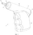
- powered driver 10 includes a housing 14, a motor 18, a driveshaft 22, and a gearbox 26.
- Housing 14 has a distal end 30 and a proximal end 34, and motor 18 is disposed within the housing with driveshaft 22 extending outwardly from distal end 30 of the housing in a direction away from proximal end 34 such that a distal end 38 of the driveshaft is spaced apart from distal end 30 of the housing.
- gearbox 26 is coupled to motor 18 and to driveshaft 22 such that activation of the motor will cause rotation of the driveshaft (suitable gearboxes described in more detail below).
- driver 10 also comprises a battery (e.g., two batteries 40, as shown) configured to power motor 18 (e.g., through electrical communication between batteries 40 and motor 18, for example, through wiring, circuitry, and/or the like).
- batteries 40 comprise two 9-volt batteries which may be commercially available from a variety of suppliers and retail outlets.
- Other embodiments can include any suitable battery and/or combination of batteries that permit the function(s) described in this disclosure.
- driver 10 does not include a "trigger” configured to be squeezed or otherwise depressed with a user's finger during use to activate the motor.
- gearbox 26 is slidably disposed in housing 14 and configured such that, upon application of a threshold force (e.g., a force at least large enough to move the driveshaft) on driveshaft 22 in direction 42 (toward proximal end 34 of the housing), the driveshaft and gearbox will slide toward the proximal end of the housing and thereby close an electrical circuit between the motor and the battery (and thus active the motor to rotate the driveshaft).
- a threshold force e.g., a force at least large enough to move the driveshaft
- driver 10 further comprises a switch 46 (e.g., having a body 50 and a piston 54 axially movable relative to the body, as shown) that is coupled to the battery and the motor (e.g., via wires or other conductors), where the switch is disposed between proximal end 34 of the housing and at least a portion of gearbox 26.
- switch 46 is configured to close the circuit (e.g., between the battery and the motor upon application of the threshold force on the driveshaft).
- motor 18 and gearbox 26 are coupled in fixed axial relation to each other and are together slidable within the housing (e.g., along axis 58).
- switch 46 is disposed between motor 18 and proximal end 34 of the housing.
- gearbox 26 (and driveshaft 22) is biased in the direction of distal end 30 (e.g., by a spring 62 disposed between the gearbox and the distal end of the housing) such that in the absence of the threshold force on the driveshaft, the circuit remains open and the motor is not active.
- motor 18 and gearbox 26 are together biased in the direction of distal end 30 of the housing by a spring 62 disposed between body 50 of the switch (e.g., and/or one or more tabs or other portions 66 of housing 14 to which the body of the switch is mounted or otherwise supported, such as, for example, against axial movement) and motor 18.
- housing 14 includes one or more internal tabs or portions 70 supporting motor 18 (e.g., against lateral displacement relative to axis 58) and permitting the motor to slide axially along axis 58 (e.g., configured to support motor 18 in coaxial alignment with axis 58).
- housing 14 also includes one or more internal tabs or portions 74 configured to limit the depth of slidable movement of motor 18 (and gearbox 26 and driveshaft 22) in direction 42.
- tabs 74 are disposed on opposite sides of spring 62 and extend within a cross-sectional perimeter of a proximal end of motor 18 such that tabs 74 physically limit movement of motor 18 in direction 42.
- housing 14 (including tabs or portions 70 and/or 74) can be provided in any structure or configuration that permits the operation describes in this disclosure (e.g., such that axial displacement of motor 18, gearbox 26, and/or driveshaft 22 is limitably permitted and lateral displacement of motor 18, gearbox 26, and/or driveshaft 22 is substantially restricted).
- Spring 62 may be configured with a spring constant of between 0.175 and 1.05 Newton per Millimetre (N/mm) (between 1 and 6 pounds of force per inch (lbf/in)). In various embodiments, spring 62 may be configured differently for different applications. For example, in embodiments of the present drivers that are configured for pediatric use, the spring may be configured with a spring constant of between 0.175 and 0.7 N/mm (e.g.
- the spring may be configured with a spring constant of between 0.35 and 1.05 N/mm (e.g., 0.52 and 0.87 N/mm) (between 2 and 6 lbf/in (e.g., 3-5 lbf/ in)); and, in embodiments of the present drivers that are configured for adult sternal insertions, the spring may be configured with a spring constant of between 0.17 and 0.7 N/mm (e.g., 0.35-0.52 N/mm) (between 1 and 4 lbf/in (e.g., 2-3 lbf/in)).
- Motors and gear assemblies satisfactory for use with a powered driver incorporating teachings of the present disclosure may be obtained from various vendors. Such motor and gear assemblies are typically ordered as “sets” with one end of each motor securely attached to an adjacent end of an associated gear assembly. A driveshaft having various dimensions and/or configurations may extend from the gear assembly opposite from the motor. The gear assemblies may sometimes be referred to as “reduction gears” or “planetary gears.” The dimensions and/or configurations of an associated housing may be modified to accommodate an associated motor and gear assembly.
- driver 10 is configured such that motor 18, gearbox 26, and driveshaft 22 are axially slidable together
- other embodiments may be configured such that the motor is held in a fixed axial position relative to the housing and the gearbox and the driveshaft slide relative to the motor (e.g., along a stub shaft extending from the motor), or such that the motor and gearbox are held in a fixed axial position relative to the housing and the driveshaft slides relative to the motor and gearbox, to activate the motor and rotate the driveshaft.
- the motor is configured to rotate at a satisfactory speed and a satisfactory torque such that the gearbox can be omitted and the motor can directly drive the driveshaft.
- housing 14 defines a primary portion 78 extending between distal end 30 and proximal end 34, and a handle portion 82 (e.g., having a central longitudinal axis 86) extending laterally from primary portion 78 at a non-parallel angle 84 (e.g., between thirty degrees (30°) and sixty degrees (60°), and in some embodiments, up to or greater than ninety degrees (90°)) relative to axis 58 of the primary portion.
- housing 14 can be described has having the general configuration of a small pistol (e.g., housing 14 resembles a pistol-grip).
- Handle portion 82 may be described as an elongated, hollow container sized to receive batteries 40, as shown.
- Housing 14 may be formed from relatively strong, heavy duty polymeric material.
- housing 14 may be formed in two halves which are joined together to form a fluid tight seal with certain components of driver 10 disposed in the housing, as shown.
- batteries 40 are not removable from housing 14.
- two halves of the housing may be glued or otherwise coupled (e.g., welded) together such that the housing generally cannot be reopened (e.g., to replace batteries) without damaging the housing.
- batteries 40 may be removable for replacement and/or recharging.
- distal end 30 of housing 14 includes an opening 90 with portions of driveshaft 22 extending therethrough.
- driver 10 further includes an O-ring (e.g., a resilient polymeric or rubber O-ring) 94 disposed around driveshaft 22 and between gearbox 26 and distal end 30 of the housing to seal opening 90.
- O-ring e.g., a resilient polymeric or rubber O-ring
- driveshaft 22 has an equilateral polygonal cross-sectional shape.
- a portion of the driveshaft terminating in distal end 38 has a pentagonal cross-sectional shape defined by five surfaces 98.
- surfaces 98 may be tapered and/or disposed at an angle relative to axis 58 (e.g., an angle of three degrees (3°) ⁇ two degrees (2°) relative to axis 58).
- a magnet can be disposed on and/or in distal end 38 of the driveshaft (e.g., or distal end 38 may otherwise be magnetic).
- Fittings and/or connectors with various dimensions and/or configurations other than the depicted configuration of distal end 38 of the driveshaft may also be satisfactorily used with a powered driver incorporating teachings of the present disclosure (e.g., in the shown embodiment, distal end 38 of driveshaft 22 is configured to releasably secure IO needle set 160, however, in other embodiments, driveshaft 22 can be configured to releasably secure other IO needle sets and comprise any associated structure).
- driveshaft 22 includes an annular groove 102 configured to receive O-ring 94 when driveshaft 22 is pressed fully in direction 42, such that O-ring 94 will contract into groove 102 and prevent driveshaft 22 from returning to its extended position.
- driver 10 can be configured as a single-use driver (e.g., to permit the use of inexpensive batteries while preventing re-use to maintain efficacy and patient safety, such as, for example, where the batteries provide sufficient power to insert a single IO device but may not provide sufficient power to insert a second IO device).
- switch 46 may be configured as a single-use switch that prevents a second activation, such as, for example, with a fuse that terminates the functionality of the switch after a single use, or a simple timer circuit that terminates the functionality of the switch after a prescribe period of time (e.g., 10 seconds) that is sufficient to insert a single IO device but not sufficient to couple a second IO device to driveshaft 22 and attempt to insert the second IO device.
- spring 62 may comprise a collapsible member and/or otherwise be configured to irreversibly yield after compression.
- driver 10 can be configured to allow removal of batteries 40 by pressing tabs or snaps incorporated into housing 14.
- tabs or snap can be located in the handle portion 82, such as one tab or snap on each side of handle portion 82. Pressing the tabs or snaps causes batteries 40 to be released from driver 10b, such as from the bottom or back side of handle portion 82, and can render the driver inoperable for future use.
- Intraosseous (IO) devices having corresponding tapered openings or connector receptacles may be releasably engaged with distal end 38 of driveshaft 22.
- distal end 38 extending may be releasably engaged with a tapered opening (e.g., 186) in a connector (e.g., 180) as shown in FIGS. 4A and 4B , which depict an example of an IO device or penetrator assembly 160 that is usable with driver 10.
- Penetrator assembly 160 as shown in FIGS. 4A and 4B may include connector 180, associated hub 200, outer penetrator 210, and inner penetrator 220.
- Penetrator assembly 160 may include an outer penetrator such as a cannula, a hollow tube or hollow drill bit, and an inner penetrator such as a stylet or trocar.
- outer penetrator or cannula 210 may be described as a generally elongated tube sized to receive inner penetrator or stylet 220 therein.
- inner penetrator 220 may be disposed within longitudinal passageway 184 extending through outer penetrator 210.
- the outside diameter of inner penetrator 220 and the inside diameter of longitudinal passageway 184 may be selected such that inner penetrator 220 may be slidably disposed within outer penetrator 210.
- Metallic disc 170 may be disposed within opening 186 for use in releasably attaching connector 180 with a magnet disposed on distal end 38 of driveshaft 22 (e.g., or an otherwise magnetic driveshaft 22). End 223 of inner penetrator 220 may be spaced from metallic disc 170 with insulating or electrically nonconductive material disposed therebetween.
- metallic disc 170 may be magnetic and the distal end 38 of driveshaft 22 and/or driveshaft 22 may comprise metallic materials configured to releasably attach to the magnetic metallic disc of connector 180.
- Tip 211 of outer penetrator 210 and/or tip 222 of inner penetrator 220 may be operable to penetrate bone and associated bone marrow.
- the configuration of tips 211 and/or 222 may be selected to penetrate a bone or other body cavities with minimal trauma.
- First end or tip 222 of inner penetrator 220 may be trapezoid shaped and may include one or more cutting surfaces.
- outer penetrator 210 and inner penetrator 220 may be ground together as one unit during an associated manufacturing process. Providing a matching fit allows respective tips 211 and 222 to act as a single drilling unit which facilitates insertion and minimizes damage as portions of penetrator assembly 160 are inserted into a bone and associated bone marrow.
- Outer penetrator 210 and/or inner penetrator 220 may be formed from stainless steel, titanium, and/or other materials of suitable strength and durability to penetrate bone.
- Hub 200 may be used to stabilize penetrator assembly 160 during insertion of an associated penetrator into a patient's skin, soft tissue, and adjacent bone at a selected insertion site.
- First end 201 of hub 200 may be operable for releasable engagement or attachment with associated connector 180.
- Second end 202 of hub 200 may have a size and configuration compatible with an associated insertion site for outer penetrator 210.
- the combination of hub 200 with outer penetrator 210 may sometimes be referred to as a "penetrator set" or "intraosseous needle.”
- Connector 180 and attached inner penetrator 220 may be releasably engaged with each other by Luer type fittings, threaded connections, and/or other suitable fittings formed on first end 201 of hub 200.
- Outer penetrator 210 extends from second end 202 of hub 200.
- connector 180 may be described as a generally cylindrical tube defined in part by first end 181 and second end 182.
- the exterior of connector 180 may include an enlarged tapered portion adjacent to end 181.
- a plurality of longitudinal ridges 190 may be formed on the exterior of connector 180 to allow an operator to grasp associated penetrator assembly 160 during attachment with a driveshaft. Longitudinal ridges 190 also allow connector 180 to be grasped for disengagement from hub 200 when outer penetrator 210 has been inserted into a bone and associated bone marrow.
- Second end 182 of connector 180 may include opening 185 sized to receive first end 201 of hub 200 therein. Threads 188 may be formed in opening 185 adjacent to second end 182 of connector 180. Threads 188 may be used in releasably attaching connector 180 with threaded fitting 208 adjacent to first end 201 of hub 200.
- First end 201 of hub 200 may include a threaded connector 208 and/or other suitable fittings formed on the exterior thereof.
- First end 201 may have a generally cylindrical pin-type configuration compatible with releasably engaging second end or box end 182 of connector 180.
- end 202 of hub 200 may have the general configuration of a flange.
- Angular slot or groove 204 sized to receive one end of protective cover or needle cap 234 may be formed in end 202.
- Slot or groove 204 may be used to releasable engage needle cover 234 (shown in FIG. 5 ) with penetrator assembly 160.
- a penetrator assembly may include only a single, hollow penetrator.
- a penetrator assembly may include an outer penetrator such as a cannula, a hollow needle or hollow drill bit, and an inner penetrator such as a stylet, trocar or other removable device disposed within the outer penetrator.
- Penetrator 210 is one example of a single, hollow penetrator or cannula.
- the size of a penetrator may vary depending upon the intended application for the associated penetrator assembly. Penetrators may be relatively small for pediatric patients, medium size for adults, and large for oversize adults. By way of example, a penetrator may range in length from five (5) mm to thirty (30) mm. The diameter of a penetrator may range from eighteen (18) gauge to ten (10) gauge. The length and diameter of the penetrator used in a particular application may depend on the size of a bone to which the apparatus may be applied. Penetrators may be provided in a wide variety of configurations depending upon intended clinical purposes for insertion of the associated penetrator. For example, there may be one configuration for administering drugs and/or fluids to a patient's bone marrow and an alternative configuration for sampling bone marrow and/or blood from a patient. Other configurations may be appropriate for bone and/or tissue biopsy.
- connector 180 may be described as having a generally cylindrical configuration defined in part by first end 181 and second end 182. Exterior portions of connector 180 may include an enlarged tapered portion adjacent to end 181. A plurality of longitudinal ridges 190 may be formed on the exterior of connector 180 to allow an operator to grasp associated penetrator assembly 160 during attachment with a drive shaft. Longitudinal ridges 190 also allow connector 180 to be grasped for disengagement from hub 200 when outer penetrator 210 has been inserted into a bone and associated bone marrow.
- First end 181 of connector of 180 may include opening 186 sized to receive portions driveshaft 22 therein.
- a plurality of webs 136 may extend radially outward from connector receptacle 186. Webs 136 may cooperate with each other to form a plurality of openings 138 adjacent to first end 181. Opening 186 and openings 138 may cooperate with each other to form portions of a connector receptacle operable to receive respective portions of a connector (not expressly shown) therein.
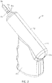
- FIGS. 5 and 6 depict side views of a second embodiment 10a of the present drivers with an IO needle set 160 ( FIGS. 4A-4B ) coupled to the driver (e.g., with distal end 38 of driveshaft 22 disposed in a receptacle or recess 186 of the IO needle set);
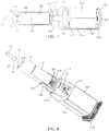
- FIG. 7 depicts a side cross-sectional view of driver 10a; and
- FIG. 8 depicts a cutaway perspective view of driver 10a.
- Driver 10a is substantially similar to driver 10 with the primary exception that housing 14a of driver 10a is not configured with a pistol-grip design (e.g., does not include a handle portion that is disposed at a non-parallel angle to rotational axis 58 of the driveshaft.
- similar reference numerals are used to designate components and assemblies that are similar and/or may even be identical (e.g., driveshaft 22 of driver 10 and driveshaft 22 of driver 10a) and dissimilar reference numerals are used to designate components and assemblies that necessarily differ (e.g., driver 10 and driver 10a, housing 14 and housing 14a).
- driver 10a primarily differs from driver 10 in that handle portion 82a of housing 14a is not disposed at a non-parallel angle relative to primary portion 78a; instead, handle portion 82a is parallel to (and, in the depicted embodiment, coaxial with) primary portion 78a.
- driver 10a comprises a switch mount 106 having a proximal end 110, a shelf 114 spaced from proximal end 110, and a pair of stepped motor guides 118 extending to a distal end 122 and including steps 126.
- shelf 114 is configured to be coupled to body 50 of switch 46, and proximal end 110 is configured to contact batteries 40 to prevent axial movement of the switch body when driver 10a is assembled.
- motor guides 118 extend parallel to planar sides of motor 18 and steps 126 limit axial movement of motor 18 relative to housing 14a (e.g., similar to as described above for tabs 74 of driver 10).
- housing 14a includes an open proximal end 34a and an end cap 130 is configured enclose the open proximal end (e.g., as shown).
- end cap 130 includes barbed tabs 134 configured to extend into corresponding openings in housing 14a to resist separation of end cap 130 from housing 14a.
- end cap 130 is additionally or alternatively coupled to housing 14a with adhesive, welds, and/or the like such that end cap 130 is not removable from housing 14a without damaging end cap 130 and/or housing 14a.
- an IO needle set 160 can be coupled to driveshaft 22 (e.g., with needle cover 234 disposed over cannula 210 and trocar 220 and received in annular groove 204, which is then removed prior to positioning the needle set for use).
- a distal end of the IO needle set can then be disposed at a desired insertion site 142 on a patient and a force applied to the distal end of the IO device via the housing of the driver such that the driveshaft of the driver slides toward proximal end 34 of the housing relative to the housing (as illustrated by the change in dimension 144 between FIGS. 5 and 6 ) and activates the motor of the driver (e.g., via operation of switch 46) to rotate the driveshaft and IO device.
- the needle set may puncture skin 146 and soft tissue 150 such that the force may be applied to the IO needle set and driveshaft by a layer of cortical bone 154 responsive to the force applied by a user on the housing in the direction of the insertion site.
- the threshold force required to move driveshaft 22 toward proximal end 34 may be low enough (e.g., spring 62 may be weak enough), that driveshaft 22 begins to move before the skin is punctured or before all of soft tissue 150 is penetrated.
- driver 10a the function of driver 10 is substantially similar in that application of a threshold force to housing 14 in the direction of an insertion site will cause motor activation via operation of switch 46, and thus rotation of the driveshaft and IO device.
- Embodiments of the present kits can comprise an embodiment of the present drivers (e.g., 10, 10a) and an IO device (e.g., 160). Some embodiments of the present kits are sterile.
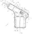
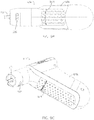
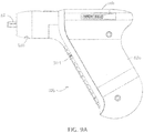
- FIGS. 9A-9C depict various views of another embodiment of driver 10b.
- Driver 10b is substantially similar in many respects to driver 10, with the primary exceptions that: (1) handle portion 82b is shaped for improved ergonomics, (2) housing 14b includes slot 300 configured to receive a portion of a mechanical lockout to prevent accidental activation of driver 10b for increased safety when handling driver 10b, and (3) housing 14b includes a slot 304 in handle portion 82b configured to receive a portion of an electrical lockout for increased safety when handling driver 10b.
- slot 300 is sized and positioned to allow a portion of a mechanical lockout to be inserted into housing 14b to prevent rearward movement of driveshaft 22 and thereby prevent closing of the electrical circuit that activates driver 10b.
- slot 304 is sized and positioned to allow a portion of an electrical lockout to be inserted into housing 14b to prevent the electrical circuit from being closed and thereby energizing driver 10b (e.g., to prevent activation of the driver during sterilization, packaging, transportation, or the like).
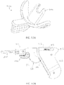
- FIG. 10A depicts a perspective view of a first embodiment of mechanical lockout 400 for use with driver 10b of FIGS. 9A-9C .
- mechanical lockout 400 is configured to be coupled to driver 10b to prevent accidental activation of driver 10b (e.g., for increased safety when handling driver 10b, such as during sterilization or transportation).
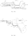
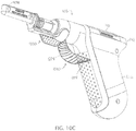
- FIGS. 10B and 10C depict side and perspective views, respectively, of mechanical lockout 400 of FIG. 10A , and an embodiment of an electrical lockout 500, in combination with driver 10b of FIGS. 9A-9C .
- mechanical lockout 400 is removably engaged with driver 10b with tab 404 of the mechanical lockout be removably inserted into slot 300 in housing 14b proximal to at least a portion of driveshaft 22.
- tab 404 extends into slot 300 and is shaped to extend around and receive a reduced-diameter part of driveshaft 22 (e.g., in a recess, as shown) to physically impede rearward movement of driveshaft 22 and gearbox 26.
- slot 300 could be located in housing 14b closer to proximal end 34b of housing 14b and still physically impede rearward movement to prevent accidental activation.
- slot 300 can be located proximal to a portion (e.g., all) of gearbox 26, or a portion (e.g., all) of motor 18.
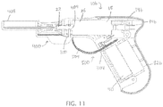
- FIG. 11 tab 404 extends into slot 300 and is shaped to extend around and receive a reduced-diameter part of driveshaft 22 (e.g., in a recess, as shown) to physically impede rearward movement of driveshaft 22 and gearbox 26.
- slot 300 could be located in housing 14b closer to proximal end 34b of housing 14b and still physically impede rearward movement to prevent accidental activation.
- slot 300 can be located
- mechanical lockout 400 upon application of a threshold force on driveshaft 22 in the direction of proximal end 34b of housing 14b, mechanical lockout 400 prevents driveshaft 22 and gearbox 26 from sliding toward proximal end 34b of housing 14b, which prevents driveshaft 22 and gearbox 26 from closing the electrical circuit between motor 18 and battery 40.
- mechanical lockout 400 also includes needle cover 408.
- FIG. 11 depicts a cross-sectional view of the lockouts of FIGS. 10B and 10C in combination with driver 10b.
- FIG. 11 depicts an embodiment of electrical lockout 500 for increased safety when handling driver 10b, such as during sterilization.
- Electrical lockout 500 comprises flexible strip 504 that is removably inserted into slot 304 in housing 14b in handle portion 82b between two electrically conductive portions of the electrical circuit to prevent driver 10b from energizing during sterilization.
- strip 504 can comprise a polymer, such as Mylar, and/or other non-conductive material.
- Electrical lockout 500 can be used with driver 10b in conjunction with any embodiment of the present mechanical lockouts (e.g., mechanical lockout 400 or mechanical lockout 400a).
- electrical lockout 500 can be coupled to mechanical lockout 400. Coupling can be achieved, for example, by attaching strip 504 to mechanical lockout 400, such as at the proximal end of mechanical lockout 400, so that strip 504 and electrical lockout 500 can be removed in a single pull when removing mechanical lockout 400.
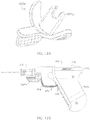
- FIG. 12A depicts a perspective view of a second embodiment of mechanical lockout 400a for use with driver 10b to prevent accidental activation of driver 10b (e.g., for increased safety when handling driver 10b, such as during sterilization, transportation, or when applying a needle set 160 to driver 10b).
- Mechanical lockout 400a is similar to mechanical lockout 400, but does not include a needle cover.
- FIG. 12B depicts a side view of mechanical lockout 400a of FIG. 12A and electrical lockout 500 in combination with driver 10b. In other embodiments, mechanical lockout 400a can also be used with driver 10b without an electrical lockout. As depicted in FIG. 12B , mechanical lockout 400a is removably engaged with driver 10b.
- Mechanical lockout 400a includes tab 404a, and similar to FIG. 11 , tab 404a can be removably inserted into slot 300 in housing 14b proximal to at least a portion of driveshaft 22. Similar to FIG. 11 , upon application of a threshold force on driveshaft 22 in the direction of proximal end 34b of housing 14b, mechanical lockout 400a prevents driveshaft 22 and gearbox 26 from sliding toward proximal end 34b of housing 14b, which prevents driveshaft 22 and gearbox 26 from closing the electrical circuit between motor 18 and battery 40.
Claims (15)
- Antrieb (10, 10a, 10b), der konfiguriert ist, um einem Benutzer beim Einführen einer intraossären (IO) Vorrichtung (160) in einen Knochen zu helfen, wobei der Antrieb Folgendes umfasst:ein Gehäuse (14, 14a, 14b), das einen primären Abschnitt (78, 78a), der sich zwischen dem distalen Ende (30) und dem proximalen Ende (34) erstreckt, und einen Griffabschnitt (82, 82a), der sich von dem primären Abschnitt erstreckt, definiert;eine Antriebswelle (22), die sich von einem distalen Ende des Gehäuses in einer Richtung von einem proximalen Ende des Gehäuses fort nach außen erstreckt, wobei die Antriebswelle mit der intraossären Vorrichtung (160) gekoppelt ist;einen Motor (18), der in dem Gehäuse (14, 14a, 14b) angeordnet ist;ein Getriebe (26), das so mit dem Motor (18) und der Antriebswelle (22) gekoppelt ist, dass die Aktivierung des Motors eine Drehung der Antriebswelle bewirkt;eine Batterie (40), die konfiguriert ist, um den Motor mit Strom zu versorgen; undeinen Schalter (46), der in dem Gehäuse (14, 14a, 14b) angeordnet ist und mit der Batterie (40) gekoppelt ist;wo eine Ausübung einer Schwellenkraft, die auf ein distales Ende der IO-Vorrichtung (160) über das Gehäuse (14, 14a, 14b) in eine Richtung einer Einführstelle ausgeübt wird, einen Betrieb des Motors über die Betätigung des Schalters (46) bewirkt, wodurch die Antriebswelle (22) und die IO-Vorrichtung (160) gedreht werden,eine mechanische Sperre (400, 400a), die konfiguriert ist, um so mit dem Gehäuse (14, 14a, 14b) gekoppelt zu werden, dass bei Ausübung einer Schwellenkraft auf die Antriebswelle (22) in Richtung des proximalen Endes des Gehäuses, die mechanische Sperre verhindert, dass die Antriebswelle (22) und das Getriebe (26) zu dem proximalen Ende des Gehäuses hin gleiten, wodurch verhindert wird, dass ein elektrischer Schaltkreis zwischen dem Motor (18) und der Batterie (40) sich schließt.
- Antrieb nach Anspruch 1, umfassend einen Schalter, (46), der in dem Gehäuse angeordnet und mit der Batterie gekoppelt ist, eine Schalterbefestigung (106), die ein proximales Ende und ein distales Ende aufweist, ein Fach (114), das von dem proximalen Ende der Schalterbefestigung beabstandet ist, und ein Paar Schrittmotorführungen (118), die sich zu einem distalen Ende der Schalterbefestigung erstreckt und Stufen (126) einschließt.
- Antrieb nach Anspruch 2, wobei das Fach (114) konfiguriert ist, um mit einem Körper (50) des Schalters (46) gekoppelt zu werden, und das proximale Ende der Schalterbefestigung (106) konfiguriert ist, um mit der Batterie (40) in Kontakt zu kommen , um eine axiale Bewegung des Schalterkörpers zu verhindern.
- Antrieb nach einem der Ansprüche 1 bis 3, ferner umfassend eine Motorführung (118), die sich parallel zu dem Motor (18) erstreckt, und eine Stufe, die konfiguriert ist, um eine axiale Bewegung des Motors bezüglich dem Gehäuse zu begrenzen.
- Antrieb nach einem der Ansprüche 1 bis 4, wobei das Gehäuse ein offenes proximales Ende (34a) und eine Endkappe (130), die konfiguriert ist, um das offene proximale Ende des Gehäuses zu beinhalten, einschließt.
- Antrieb nach Anspruch 5, wobei die Endkappe (130) mit Widerhaken versehene Laschen (134) einschließt, die konfiguriert sind, um sich in entsprechende Öffnungen in dem Gehäuse zu erstrecken, um einer Trennung der Endkappe vom Gehäuse entgegenzuwirken, und wobei die Endkappe ferner mit dem Gehäuse mit Klebstoff, Schweißnähten und/oder dergleichen gekoppelt ist, so dass die Endkappe nicht von dem Gehäuse gelöst werden kann, ohne die Endkappe und/oder das Gehäuse zu beschädigen.
- Antrieb nach einem der Ansprüche 1 bis 6, wobei die Antriebswelle (22) eine ringförmige Rille (102) einschließt, die konfiguriert ist, um einen O-Ring (94) aufzunehmen, wenn die Antriebswelle vollständig in eine Richtung zu dem proximalen Ende des Gehäuses hin gedrückt wird, so dass der O-Ring sich in der Rille zusammenzieht und die Antriebswelle daran hindert in eine ausgedehnte Position zurückzukehren.
- Antrieb nach einem der Ansprüche 1 bis 7, wobei das Getriebe (26) und die Antriebswelle (22) in Richtung des distalen Endes des Gehäuses durch eine Feder (62) vorgespannt werden, so dass der Motor in Abwesenheit der Schwellenkraft auf der Antriebswelle inaktiv bleibt.
- Antrieb nach Anspruch 8, wobei die Feder (62) zwischen dem Körper (50) des Schalters (46) und dem Motor (18) angeordnet ist, so dass der Motor und das Getriebe (26) zusammen in Richtung des distalen Endes des Gehäuses vorgespannt werden.
- Antrieb nach einem der Ansprüche 1 bis 9, wobei das Gehäuse ferner eine oder mehrere Laschen (66) umfasst, an denen der Körper (50) des Schalters (46) angebracht ist oder andernfalls gegen eine axiale Bewegung getragen wird.
- Antrieb nach einem der Ansprüche 1 bis 10, wobei das Gehäuse ferner eine oder mehrere innere Laschen (70) umfasst, die den Motor (18) gegen eine seitliche Verschiebung bezüglich einer Achse des primären Abschnitts des Gehäuses stützen und dem Motor gestatten axial entlang der Achse des primären Abschnitts des Gehäuses zu gleiten.
- Antrieb nach einem der Ansprüche 1 bis 11, wobei das Gehäuse ferner einen oder mehrere innere Abschnitte (74) umfasst, die konfiguriert sind, um eine Tiefe der gleitbaren Bewegung des Motors in eine Richtung zu dem proximalen Ende des Gehäuses hin zu begrenzen.
- Antrieb nach Anspruch 12, wobei die inneren Abschnitte (74) auf gegenüberliegenden Seiten der Feder (62) angeordnet sind und sich innerhalb eines Querschnittsperimeters eines proximalen Endes des Motors (18) erstrecken, so dass die inneren Abschnitte eine Bewegung des Motors in Richtungen zu dem proximalen Ende des Gehäuses hin physisch begrenzen.
- Antrieb nach einem der Ansprüche 1 bis 13, wobei der primäre Abschnitt des Gehäuses ferner einen Schlitz (300) einschließt, der konfiguriert ist, um einen Abschnitt (404) der mechanischen Sperre (400) aufzunehmen, um einen unbeabsichtigten Betrieb des Antriebs zu verhindern, wo der Schlitz bemessen und positioniert ist, um einem Abschnitt der mechanischen Sperre zu gestatten in das Gehäuse eingeführt zu werden, um eine rückwärtige Bewegung der Antriebswelle zu verhindern und dadurch den Betrieb des Motors zu verhindern.
- Antrieb nach einem der Ansprüche 1 bis 14, wobei der Griffabschnitt des Gehäuses ferner einen Schlitz (304) einschließt, der konfiguriert ist, um einen Abschnitt einer elektrischen Sperre (500) aufzunehmen, wobei der Schlitz bemessen und positioniert ist, um einem Abschnitt der elektrischen Sperre zu gestatten in das Gehäuse eingeführt zu werden, um einen Betrieb des Motors zu verhindern.
Applications Claiming Priority (4)
| Application Number | Priority Date | Filing Date | Title |
|---|---|---|---|
| US201461940741P | 2014-02-17 | 2014-02-17 | |
| US201461945325P | 2014-02-27 | 2014-02-27 | |
| EP15748939.4A EP3107692B1 (de) | 2014-02-17 | 2015-02-17 | Durch die kraft auf die antriebswelle betätigter elektrisch betriebener treiber sowie entsprechende kits, komponenten und verfahren |
| PCT/US2015/016119 WO2015123660A1 (en) | 2014-02-17 | 2015-02-17 | Powered driver actuated by force on driveshaft and related kits, components, and methods |
Related Parent Applications (2)
| Application Number | Title | Priority Date | Filing Date |
|---|---|---|---|
| EP15748939.4A Division EP3107692B1 (de) | 2014-02-17 | 2015-02-17 | Durch die kraft auf die antriebswelle betätigter elektrisch betriebener treiber sowie entsprechende kits, komponenten und verfahren |
| EP15748939.4A Division-Into EP3107692B1 (de) | 2014-02-17 | 2015-02-17 | Durch die kraft auf die antriebswelle betätigter elektrisch betriebener treiber sowie entsprechende kits, komponenten und verfahren |
Publications (2)
| Publication Number | Publication Date |
|---|---|
| EP3434418A1 EP3434418A1 (de) | 2019-01-30 |
| EP3434418B1 true EP3434418B1 (de) | 2021-01-27 |
Family
ID=53797023
Family Applications (2)
| Application Number | Title | Priority Date | Filing Date |
|---|---|---|---|
| EP18196028.7A Active EP3434418B1 (de) | 2014-02-17 | 2015-02-17 | Treiber für knochenschraube |
| EP15748939.4A Active EP3107692B1 (de) | 2014-02-17 | 2015-02-17 | Durch die kraft auf die antriebswelle betätigter elektrisch betriebener treiber sowie entsprechende kits, komponenten und verfahren |
Family Applications After (1)
| Application Number | Title | Priority Date | Filing Date |
|---|---|---|---|
| EP15748939.4A Active EP3107692B1 (de) | 2014-02-17 | 2015-02-17 | Durch die kraft auf die antriebswelle betätigter elektrisch betriebener treiber sowie entsprechende kits, komponenten und verfahren |
Country Status (5)
| Country | Link |
|---|---|
| US (4) | US10092320B2 (de) |
| EP (2) | EP3434418B1 (de) |
| JP (2) | JP6860346B2 (de) |
| CN (2) | CN110200663B (de) |
| WO (1) | WO2015123660A1 (de) |
Families Citing this family (33)
| Publication number | Priority date | Publication date | Assignee | Title |
|---|---|---|---|---|
| US20030225344A1 (en) | 2002-05-31 | 2003-12-04 | Vidacare Corporation | Apparatus and method to access the bone marrow for oncology and stem cell applications |
| US10973545B2 (en) | 2002-05-31 | 2021-04-13 | Teleflex Life Sciences Limited | Powered drivers, intraosseous devices and methods to access bone marrow |
| US11337728B2 (en) | 2002-05-31 | 2022-05-24 | Teleflex Life Sciences Limited | Powered drivers, intraosseous devices and methods to access bone marrow |
| US8641715B2 (en) | 2002-05-31 | 2014-02-04 | Vidacare Corporation | Manual intraosseous device |
| US8668698B2 (en) | 2002-05-31 | 2014-03-11 | Vidacare Corporation | Assembly for coupling powered driver with intraosseous device |
| US9504477B2 (en) * | 2003-05-30 | 2016-11-29 | Vidacare LLC | Powered driver |
| US8944069B2 (en) | 2006-09-12 | 2015-02-03 | Vidacare Corporation | Assemblies for coupling intraosseous (IO) devices to powered drivers |
| US10028834B2 (en) | 2011-01-31 | 2018-07-24 | St. Jude Medical, Inc. | Adjustable prosthetic anatomical device holder and handle for the implantation of an annuloplasty ring |
| ES2610079T3 (es) | 2011-01-31 | 2017-04-25 | St. Jude Medical, Inc. | Herramienta para el ajuste de un dispositivo anatómico protésico |
| ES2589503T3 (es) * | 2011-01-31 | 2016-11-14 | St. Jude Medical, Inc. | Característica de bloqueo antirrotación |
| WO2013098823A2 (en) | 2011-12-28 | 2013-07-04 | Clil Medical Ltd. | System and method for blood filtering and/or treatment |
| US10993729B1 (en) * | 2014-07-02 | 2021-05-04 | Insurgical, Inc. | Sterile ready-to-use surgical tool and attachment system |
| BR112018074199A2 (pt) | 2016-05-25 | 2019-03-06 | 3D Biopsy, Inc. | projeto de agulha de biopsia |
| AU2017345349B2 (en) | 2016-10-18 | 2022-08-11 | Piper Access, Llc | Intraosseous access devices, systems, and methods |
| JP7065846B2 (ja) | 2016-10-27 | 2022-05-12 | シー・アール・バード・インコーポレーテッド | 骨内アクセスデバイス |
| WO2018165334A1 (en) | 2017-03-07 | 2018-09-13 | Piper Access, Llc. | Safety shields for elongated instruments and related systems and methods |
| WO2018165339A1 (en) | 2017-03-10 | 2018-09-13 | Piper Access, Llc. | Securement devices, systems, and methods |
| US20200330129A9 (en) | 2017-09-09 | 2020-10-22 | June Medical Ip, Llc | Passive safety intraosseous device |
| US20190314059A1 (en) | 2017-09-09 | 2019-10-17 | Billie Coppedge | Cannula with recessed hub structure |
| WO2019049098A1 (en) * | 2017-09-11 | 2019-03-14 | Teleflex Medical Devices S.A.R.L. | FEED INTRA-BONE DRIVING DEVICE WITH PROTECTIVE ELEMENT, AND RELATED KITS, COMPONENTS, AND METHODS |
| US11304709B2 (en) | 2018-01-25 | 2022-04-19 | Medtronic Holdings Company Sarl | Adaptor and drill for use with a driver and a cannula for drilling into bone |
| US10980587B2 (en) * | 2018-01-25 | 2021-04-20 | Medtronic Holding Company Sàrl | Adaptor for use with a driver, a drill, and a cannula for drilling into bone |
| EP3755247B1 (de) | 2018-02-20 | 2023-07-05 | Piper Access, LLC | Bohrvorrichtungen und zugehörige verfahren |
| KR20210030387A (ko) * | 2018-07-03 | 2021-03-17 | 보소닉 아게 | 치밀골층을 천공하기 위한 장치 |
| PL3663046T3 (pl) | 2018-12-07 | 2022-01-10 | SWEDEX GmbH Industrieprodukte | Układ wkrętarkowy oraz sposób eksploatacji układu wkrętarkowego |
| WO2020150314A1 (en) * | 2019-01-17 | 2020-07-23 | Medtronic Holding Company Sarl | Adaptor and drill for use with a driver and a cannula for drilling into bone |
| CN112568961A (zh) | 2019-09-27 | 2021-03-30 | 巴德阿克塞斯系统股份有限公司 | 骨内装置的自动推进特征 |
| WO2021062385A1 (en) * | 2019-09-27 | 2021-04-01 | Bard Access Systems, Inc. | Constant-torque intraosseous access devices and methods thereof |
| EP4031027A4 (de) * | 2019-09-27 | 2023-09-13 | Bard Access Systems, Inc. | Verschiedene betriebsmechanismen für medizinprodukte für den intraossären zugang und verfahren dafür |
| WO2021119080A1 (en) * | 2019-12-11 | 2021-06-17 | Merit Medical Systems, Inc. | Bone biopsy device and related methods |
| US20210275154A1 (en) * | 2020-03-03 | 2021-09-09 | Merit Medical Systems, Inc. | Bone biopsy device and related methods |
| US11896264B2 (en) * | 2020-04-21 | 2024-02-13 | Bard Access Systems, Inc. | Reusable push-activated intraosseous access device |
| EP4287952A1 (de) | 2021-02-08 | 2023-12-13 | Bard Access Systems, Inc. | Intraossäre modulare stromversorgung |
Family Cites Families (30)
| Publication number | Priority date | Publication date | Assignee | Title |
|---|---|---|---|---|
| US1954620A (en) | 1932-04-25 | 1934-04-10 | Edwin L Connell | Clutch |
| CN1081453C (zh) * | 1994-03-19 | 2002-03-27 | 广东省医疗器械研究所 | 一种新型的电动手术机 |
| DE19527193A1 (de) * | 1995-07-26 | 1997-01-30 | Hilti Ag | Schraubgerät |
| US5747953A (en) * | 1996-03-29 | 1998-05-05 | Stryker Corporation | Cordless, battery operated surical tool |
| US20030089511A1 (en) * | 2001-11-12 | 2003-05-15 | Yukio Tsuneda | Electric tool |
| US9451968B2 (en) * | 2002-05-31 | 2016-09-27 | Vidacare LLC | Powered drivers, intraosseous devices and methods to access bone marrow |
| US20070049945A1 (en) | 2002-05-31 | 2007-03-01 | Miller Larry J | Apparatus and methods to install, support and/or monitor performance of intraosseous devices |
| US8641715B2 (en) * | 2002-05-31 | 2014-02-04 | Vidacare Corporation | Manual intraosseous device |
| US20030225344A1 (en) * | 2002-05-31 | 2003-12-04 | Vidacare Corporation | Apparatus and method to access the bone marrow for oncology and stem cell applications |
| US8142365B2 (en) * | 2002-05-31 | 2012-03-27 | Vidacare Corporation | Apparatus and method for accessing the bone marrow of the sternum |
| US9504477B2 (en) * | 2003-05-30 | 2016-11-29 | Vidacare LLC | Powered driver |
| US20050082389A1 (en) | 2003-10-07 | 2005-04-21 | Sanchez Michael J. | Methods and apparatus for battery powered hand-held sprayer with remote spray gun assembly |
| US20090090763A1 (en) * | 2007-10-05 | 2009-04-09 | Tyco Healthcare Group Lp | Powered surgical stapling device |
| FR2861572B1 (fr) | 2003-10-30 | 2006-07-28 | Patrice Richard | Dispositif de prelevement et/ou d'injection de moelle osseuse et systeme comprenant un tel dispositif |
| CN101474088B (zh) * | 2004-01-26 | 2011-12-14 | 维达保健公司 | 手动式骨内器械 |
| WO2005097411A2 (en) | 2004-03-30 | 2005-10-20 | Kinamed, Inc. | Powered surgical screwdriver |
| JP2005286256A (ja) | 2004-03-31 | 2005-10-13 | Nec Electronics Corp | 半導体装置及びその製造方法 |
| US7644848B2 (en) * | 2006-01-31 | 2010-01-12 | Ethicon Endo-Surgery, Inc. | Electronic lockouts and surgical instrument including same |
| JP4603521B2 (ja) | 2006-09-07 | 2010-12-22 | 日東工器株式会社 | 電動ドライバ及び電動ドライバ装置 |
| CN101355981A (zh) * | 2006-09-12 | 2009-01-28 | 维达保健公司 | 骨髓抽吸装置及相关方法 |
| WO2008103839A2 (en) * | 2007-02-22 | 2008-08-28 | Spine View, Inc. | Expandable rotating device and method for tissue aspiration |
| AU2009262866B2 (en) * | 2008-06-26 | 2013-02-21 | Wayne Anderson | Depth controllable and measurable medical driver devices and methods of use |
| WO2010078436A2 (en) * | 2008-12-30 | 2010-07-08 | Brandon Mark L | Minimally invasive endoscopic systems for placing intramedullary nails and methods therefor |
| WO2011085194A1 (en) | 2010-01-07 | 2011-07-14 | Black & Decker Inc. | Power screwdriver having rotary input control |
| US9381058B2 (en) | 2010-11-05 | 2016-07-05 | Ethicon Endo-Surgery, Llc | Recharge system for medical devices |
| TWI409055B (zh) * | 2011-05-17 | 2013-09-21 | Univ Chang Gung | 膝關節外骨骼步行復健設備 |
| GB2492091B (en) * | 2011-06-21 | 2018-04-04 | Seatriever International Holdings Ltd | An illumination device for a balloon |
| US9427505B2 (en) | 2012-05-15 | 2016-08-30 | Smith & Nephew Plc | Negative pressure wound therapy apparatus |
| CN103558786B (zh) * | 2013-10-31 | 2016-01-13 | 哈尔滨工业大学 | 基于嵌入Android移动终端及FPGA的手部功能康复机器人人机交互控制系统 |
| US20150171504A1 (en) | 2013-12-13 | 2015-06-18 | Kabushiki Kaisha Toshiba | Electronic apparatus |
-
2015
- 2015-02-17 CN CN201910527327.7A patent/CN110200663B/zh active Active
- 2015-02-17 CN CN201580019471.XA patent/CN106470801B/zh active Active
- 2015-02-17 EP EP18196028.7A patent/EP3434418B1/de active Active
- 2015-02-17 US US14/624,219 patent/US10092320B2/en active Active
- 2015-02-17 EP EP15748939.4A patent/EP3107692B1/de active Active
- 2015-02-17 WO PCT/US2015/016119 patent/WO2015123660A1/en active Application Filing
- 2015-02-17 JP JP2016552558A patent/JP6860346B2/ja active Active
-
2018
- 2018-09-19 US US16/135,161 patent/US10653448B2/en active Active
-
2020
- 2020-01-06 JP JP2020000339A patent/JP7206448B2/ja active Active
- 2020-05-15 US US16/875,338 patent/US11547445B2/en active Active
-
2023
- 2023-01-09 US US18/094,657 patent/US20230157725A1/en active Pending
Non-Patent Citations (1)
| Title |
|---|
| None * |
Also Published As
| Publication number | Publication date |
|---|---|
| US20200275952A1 (en) | 2020-09-03 |
| US10653448B2 (en) | 2020-05-19 |
| CN110200663A (zh) | 2019-09-06 |
| CN106470801A (zh) | 2017-03-01 |
| CN110200663B (zh) | 2022-04-29 |
| US10092320B2 (en) | 2018-10-09 |
| US20230157725A1 (en) | 2023-05-25 |
| EP3107692A4 (de) | 2017-10-18 |
| EP3434418A1 (de) | 2019-01-30 |
| CN106470801B (zh) | 2019-07-12 |
| EP3107692A1 (de) | 2016-12-28 |
| US20150230823A1 (en) | 2015-08-20 |
| JP7206448B2 (ja) | 2023-01-18 |
| JP2020168355A (ja) | 2020-10-15 |
| US20190015133A1 (en) | 2019-01-17 |
| EP3107692B1 (de) | 2018-11-21 |
| WO2015123660A1 (en) | 2015-08-20 |
| JP6860346B2 (ja) | 2021-04-21 |
| JP2017514538A (ja) | 2017-06-08 |
| US11547445B2 (en) | 2023-01-10 |
Similar Documents
| Publication | Publication Date | Title |
|---|---|---|
| US11547445B2 (en) | Powered driver actuated by force on driveshaft and related kits, components, and methods | |
| US11771439B2 (en) | Powered driver | |
| TWI341738B (en) | Apparatus for penetrting a bone and providing access to associated bone marrow | |
| US9451968B2 (en) | Powered drivers, intraosseous devices and methods to access bone marrow | |
| EP2131751B1 (de) | Elektrisch betriebenes antriebsgerät | |
| US20180221570A1 (en) | Pumping apparatuses and methods for fluid infusion | |
| US11337728B2 (en) | Powered drivers, intraosseous devices and methods to access bone marrow | |
| US11678909B2 (en) | Powered intraosseous driver with protective member, and related kits, components, and methods | |
| CN111163718B (zh) | 具有保护构件的动力骨内驱动器以及相关的套件、部件和方法 |
Legal Events
| Date | Code | Title | Description |
|---|---|---|---|
| PUAI | Public reference made under article 153(3) epc to a published international application that has entered the european phase |
Free format text: ORIGINAL CODE: 0009012 |
|
| STAA | Information on the status of an ep patent application or granted ep patent |
Free format text: STATUS: THE APPLICATION HAS BEEN PUBLISHED |
|
| AC | Divisional application: reference to earlier application |
Ref document number: 3107692 Country of ref document: EP Kind code of ref document: P |
|
| AK | Designated contracting states |
Kind code of ref document: A1 Designated state(s): AL AT BE BG CH CY CZ DE DK EE ES FI FR GB GR HR HU IE IS IT LI LT LU LV MC MK MT NL NO PL PT RO RS SE SI SK SM TR |
|
| STAA | Information on the status of an ep patent application or granted ep patent |
Free format text: STATUS: REQUEST FOR EXAMINATION WAS MADE |
|
| 17P | Request for examination filed |
Effective date: 20190726 |
|
| RBV | Designated contracting states (corrected) |
Designated state(s): AL AT BE BG CH CY CZ DE DK EE ES FI FR GB GR HR HU IE IS IT LI LT LU LV MC MK MT NL NO PL PT RO RS SE SI SK SM TR |
|
| GRAP | Despatch of communication of intention to grant a patent |
Free format text: ORIGINAL CODE: EPIDOSNIGR1 |
|
| STAA | Information on the status of an ep patent application or granted ep patent |
Free format text: STATUS: GRANT OF PATENT IS INTENDED |
|
| INTG | Intention to grant announced |
Effective date: 20200114 |
|
| GRAS | Grant fee paid |
Free format text: ORIGINAL CODE: EPIDOSNIGR3 |
|
| GRAA | (expected) grant |
Free format text: ORIGINAL CODE: 0009210 |
|
| STAA | Information on the status of an ep patent application or granted ep patent |
Free format text: STATUS: THE PATENT HAS BEEN GRANTED |
|
| AC | Divisional application: reference to earlier application |
Ref document number: 3107692 Country of ref document: EP Kind code of ref document: P |
|
| AK | Designated contracting states |
Kind code of ref document: B1 Designated state(s): AL AT BE BG CH CY CZ DE DK EE ES FI FR GB GR HR HU IE IS IT LI LT LU LV MC MK MT NL NO PL PT RO RS SE SI SK SM TR |
|
| REG | Reference to a national code |
Ref country code: GB Ref legal event code: FG4D |
|
| REG | Reference to a national code |
Ref country code: CH Ref legal event code: EP |
|
| REG | Reference to a national code |
Ref country code: AT Ref legal event code: REF Ref document number: 1357916 Country of ref document: AT Kind code of ref document: T Effective date: 20210215 |
|
| REG | Reference to a national code |
Ref country code: IE Ref legal event code: FG4D |
|
| REG | Reference to a national code |
Ref country code: DE Ref legal event code: R096 Ref document number: 602015065388 Country of ref document: DE |
|
| REG | Reference to a national code |
Ref country code: NL Ref legal event code: MP Effective date: 20210127 |
|
| REG | Reference to a national code |
Ref country code: LT Ref legal event code: MG9D |
|
| REG | Reference to a national code |
Ref country code: AT Ref legal event code: MK05 Ref document number: 1357916 Country of ref document: AT Kind code of ref document: T Effective date: 20210127 |
|
| PG25 | Lapsed in a contracting state [announced via postgrant information from national office to epo] |
Ref country code: LT Free format text: LAPSE BECAUSE OF FAILURE TO SUBMIT A TRANSLATION OF THE DESCRIPTION OR TO PAY THE FEE WITHIN THE PRESCRIBED TIME-LIMIT Effective date: 20210127 Ref country code: PT Free format text: LAPSE BECAUSE OF FAILURE TO SUBMIT A TRANSLATION OF THE DESCRIPTION OR TO PAY THE FEE WITHIN THE PRESCRIBED TIME-LIMIT Effective date: 20210527 Ref country code: NO Free format text: LAPSE BECAUSE OF FAILURE TO SUBMIT A TRANSLATION OF THE DESCRIPTION OR TO PAY THE FEE WITHIN THE PRESCRIBED TIME-LIMIT Effective date: 20210427 Ref country code: GR Free format text: LAPSE BECAUSE OF FAILURE TO SUBMIT A TRANSLATION OF THE DESCRIPTION OR TO PAY THE FEE WITHIN THE PRESCRIBED TIME-LIMIT Effective date: 20210428 Ref country code: HR Free format text: LAPSE BECAUSE OF FAILURE TO SUBMIT A TRANSLATION OF THE DESCRIPTION OR TO PAY THE FEE WITHIN THE PRESCRIBED TIME-LIMIT Effective date: 20210127 Ref country code: FI Free format text: LAPSE BECAUSE OF FAILURE TO SUBMIT A TRANSLATION OF THE DESCRIPTION OR TO PAY THE FEE WITHIN THE PRESCRIBED TIME-LIMIT Effective date: 20210127 Ref country code: BG Free format text: LAPSE BECAUSE OF FAILURE TO SUBMIT A TRANSLATION OF THE DESCRIPTION OR TO PAY THE FEE WITHIN THE PRESCRIBED TIME-LIMIT Effective date: 20210427 |
|
| PG25 | Lapsed in a contracting state [announced via postgrant information from national office to epo] |
Ref country code: RS Free format text: LAPSE BECAUSE OF FAILURE TO SUBMIT A TRANSLATION OF THE DESCRIPTION OR TO PAY THE FEE WITHIN THE PRESCRIBED TIME-LIMIT Effective date: 20210127 Ref country code: PL Free format text: LAPSE BECAUSE OF FAILURE TO SUBMIT A TRANSLATION OF THE DESCRIPTION OR TO PAY THE FEE WITHIN THE PRESCRIBED TIME-LIMIT Effective date: 20210127 Ref country code: LV Free format text: LAPSE BECAUSE OF FAILURE TO SUBMIT A TRANSLATION OF THE DESCRIPTION OR TO PAY THE FEE WITHIN THE PRESCRIBED TIME-LIMIT Effective date: 20210127 Ref country code: AT Free format text: LAPSE BECAUSE OF FAILURE TO SUBMIT A TRANSLATION OF THE DESCRIPTION OR TO PAY THE FEE WITHIN THE PRESCRIBED TIME-LIMIT Effective date: 20210127 Ref country code: SE Free format text: LAPSE BECAUSE OF FAILURE TO SUBMIT A TRANSLATION OF THE DESCRIPTION OR TO PAY THE FEE WITHIN THE PRESCRIBED TIME-LIMIT Effective date: 20210127 |
|
| PG25 | Lapsed in a contracting state [announced via postgrant information from national office to epo] |
Ref country code: IS Free format text: LAPSE BECAUSE OF FAILURE TO SUBMIT A TRANSLATION OF THE DESCRIPTION OR TO PAY THE FEE WITHIN THE PRESCRIBED TIME-LIMIT Effective date: 20210527 |
|
| REG | Reference to a national code |
Ref country code: BE Ref legal event code: MM Effective date: 20210228 |
|
| REG | Reference to a national code |
Ref country code: DE Ref legal event code: R097 Ref document number: 602015065388 Country of ref document: DE |
|
| PG25 | Lapsed in a contracting state [announced via postgrant information from national office to epo] |
Ref country code: EE Free format text: LAPSE BECAUSE OF FAILURE TO SUBMIT A TRANSLATION OF THE DESCRIPTION OR TO PAY THE FEE WITHIN THE PRESCRIBED TIME-LIMIT Effective date: 20210127 Ref country code: CZ Free format text: LAPSE BECAUSE OF FAILURE TO SUBMIT A TRANSLATION OF THE DESCRIPTION OR TO PAY THE FEE WITHIN THE PRESCRIBED TIME-LIMIT Effective date: 20210127 Ref country code: LU Free format text: LAPSE BECAUSE OF NON-PAYMENT OF DUE FEES Effective date: 20210217 Ref country code: LI Free format text: LAPSE BECAUSE OF NON-PAYMENT OF DUE FEES Effective date: 20210228 Ref country code: MC Free format text: LAPSE BECAUSE OF FAILURE TO SUBMIT A TRANSLATION OF THE DESCRIPTION OR TO PAY THE FEE WITHIN THE PRESCRIBED TIME-LIMIT Effective date: 20210127 Ref country code: CH Free format text: LAPSE BECAUSE OF NON-PAYMENT OF DUE FEES Effective date: 20210228 Ref country code: SM Free format text: LAPSE BECAUSE OF FAILURE TO SUBMIT A TRANSLATION OF THE DESCRIPTION OR TO PAY THE FEE WITHIN THE PRESCRIBED TIME-LIMIT Effective date: 20210127 |
|
| PG25 | Lapsed in a contracting state [announced via postgrant information from national office to epo] |
Ref country code: DK Free format text: LAPSE BECAUSE OF FAILURE TO SUBMIT A TRANSLATION OF THE DESCRIPTION OR TO PAY THE FEE WITHIN THE PRESCRIBED TIME-LIMIT Effective date: 20210127 Ref country code: RO Free format text: LAPSE BECAUSE OF FAILURE TO SUBMIT A TRANSLATION OF THE DESCRIPTION OR TO PAY THE FEE WITHIN THE PRESCRIBED TIME-LIMIT Effective date: 20210127 Ref country code: SK Free format text: LAPSE BECAUSE OF FAILURE TO SUBMIT A TRANSLATION OF THE DESCRIPTION OR TO PAY THE FEE WITHIN THE PRESCRIBED TIME-LIMIT Effective date: 20210127 |
|
| PLBE | No opposition filed within time limit |
Free format text: ORIGINAL CODE: 0009261 |
|
| STAA | Information on the status of an ep patent application or granted ep patent |
Free format text: STATUS: NO OPPOSITION FILED WITHIN TIME LIMIT |
|
| 26N | No opposition filed |
Effective date: 20211028 |
|
| REG | Reference to a national code |
Ref country code: DE Ref legal event code: R081 Ref document number: 602015065388 Country of ref document: DE Owner name: TELEFLEX LIFE SCIENCES LTD., MT Free format text: FORMER OWNER: TELEFLEX MEDICAL DEVICES S.A.R.L., LUXEMBOURG, LU |
|
| PG25 | Lapsed in a contracting state [announced via postgrant information from national office to epo] |
Ref country code: IE Free format text: LAPSE BECAUSE OF NON-PAYMENT OF DUE FEES Effective date: 20210217 Ref country code: AL Free format text: LAPSE BECAUSE OF FAILURE TO SUBMIT A TRANSLATION OF THE DESCRIPTION OR TO PAY THE FEE WITHIN THE PRESCRIBED TIME-LIMIT Effective date: 20210127 Ref country code: ES Free format text: LAPSE BECAUSE OF FAILURE TO SUBMIT A TRANSLATION OF THE DESCRIPTION OR TO PAY THE FEE WITHIN THE PRESCRIBED TIME-LIMIT Effective date: 20210127 |
|
| REG | Reference to a national code |
Ref country code: GB Ref legal event code: 732E Free format text: REGISTERED BETWEEN 20220106 AND 20220112 |
|
| PG25 | Lapsed in a contracting state [announced via postgrant information from national office to epo] |
Ref country code: SI Free format text: LAPSE BECAUSE OF FAILURE TO SUBMIT A TRANSLATION OF THE DESCRIPTION OR TO PAY THE FEE WITHIN THE PRESCRIBED TIME-LIMIT Effective date: 20210127 |
|
| PG25 | Lapsed in a contracting state [announced via postgrant information from national office to epo] |
Ref country code: IS Free format text: LAPSE BECAUSE OF FAILURE TO SUBMIT A TRANSLATION OF THE DESCRIPTION OR TO PAY THE FEE WITHIN THE PRESCRIBED TIME-LIMIT Effective date: 20210527 |
|
| PG25 | Lapsed in a contracting state [announced via postgrant information from national office to epo] |
Ref country code: BE Free format text: LAPSE BECAUSE OF NON-PAYMENT OF DUE FEES Effective date: 20210228 |
|
| PGFP | Annual fee paid to national office [announced via postgrant information from national office to epo] |
Ref country code: FR Payment date: 20230223 Year of fee payment: 9 |
|
| PGFP | Annual fee paid to national office [announced via postgrant information from national office to epo] |
Ref country code: IT Payment date: 20230221 Year of fee payment: 9 Ref country code: GB Payment date: 20230227 Year of fee payment: 9 Ref country code: DE Payment date: 20230223 Year of fee payment: 9 |
|
| PG25 | Lapsed in a contracting state [announced via postgrant information from national office to epo] |
Ref country code: NL Free format text: LAPSE BECAUSE OF NON-PAYMENT OF DUE FEES Effective date: 20210127 Ref country code: CY Free format text: LAPSE BECAUSE OF FAILURE TO SUBMIT A TRANSLATION OF THE DESCRIPTION OR TO PAY THE FEE WITHIN THE PRESCRIBED TIME-LIMIT Effective date: 20210127 |
|
| PG25 | Lapsed in a contracting state [announced via postgrant information from national office to epo] |
Ref country code: HU Free format text: LAPSE BECAUSE OF FAILURE TO SUBMIT A TRANSLATION OF THE DESCRIPTION OR TO PAY THE FEE WITHIN THE PRESCRIBED TIME-LIMIT; INVALID AB INITIO Effective date: 20150217 |