EP3434306B1 - Gas-fluid separation device - Google Patents
Gas-fluid separation device Download PDFInfo
- Publication number
- EP3434306B1 EP3434306B1 EP18196343.0A EP18196343A EP3434306B1 EP 3434306 B1 EP3434306 B1 EP 3434306B1 EP 18196343 A EP18196343 A EP 18196343A EP 3434306 B1 EP3434306 B1 EP 3434306B1
- Authority
- EP
- European Patent Office
- Prior art keywords
- fluid
- gas
- patient
- chamber
- cavity
- Prior art date
- Legal status (The legal status is an assumption and is not a legal conclusion. Google has not performed a legal analysis and makes no representation as to the accuracy of the status listed.)
- Active
Links
Images


Classifications
-
- A—HUMAN NECESSITIES
- A61—MEDICAL OR VETERINARY SCIENCE; HYGIENE
- A61M—DEVICES FOR INTRODUCING MEDIA INTO, OR ONTO, THE BODY; DEVICES FOR TRANSDUCING BODY MEDIA OR FOR TAKING MEDIA FROM THE BODY; DEVICES FOR PRODUCING OR ENDING SLEEP OR STUPOR
- A61M13/00—Insufflators for therapeutic or disinfectant purposes, i.e. devices for blowing a gas, powder or vapour into the body
- A61M13/003—Blowing gases other than for carrying powders, e.g. for inflating, dilating or rinsing
-
- A—HUMAN NECESSITIES
- A61—MEDICAL OR VETERINARY SCIENCE; HYGIENE
- A61M—DEVICES FOR INTRODUCING MEDIA INTO, OR ONTO, THE BODY; DEVICES FOR TRANSDUCING BODY MEDIA OR FOR TAKING MEDIA FROM THE BODY; DEVICES FOR PRODUCING OR ENDING SLEEP OR STUPOR
- A61M1/00—Suction or pumping devices for medical purposes; Devices for carrying-off, for treatment of, or for carrying-over, body-liquids; Drainage systems
- A61M1/14—Dialysis systems; Artificial kidneys; Blood oxygenators ; Reciprocating systems for treatment of body fluids, e.g. single needle systems for hemofiltration or pheresis
- A61M1/28—Peritoneal dialysis ; Other peritoneal treatment, e.g. oxygenation
-
- A—HUMAN NECESSITIES
- A61—MEDICAL OR VETERINARY SCIENCE; HYGIENE
- A61M—DEVICES FOR INTRODUCING MEDIA INTO, OR ONTO, THE BODY; DEVICES FOR TRANSDUCING BODY MEDIA OR FOR TAKING MEDIA FROM THE BODY; DEVICES FOR PRODUCING OR ENDING SLEEP OR STUPOR
- A61M1/00—Suction or pumping devices for medical purposes; Devices for carrying-off, for treatment of, or for carrying-over, body-liquids; Drainage systems
- A61M1/36—Other treatment of blood in a by-pass of the natural circulatory system, e.g. temperature adaptation, irradiation ; Extra-corporeal blood circuits
- A61M1/3601—Extra-corporeal circuits in which the blood fluid passes more than once through the treatment unit
- A61M1/3603—Extra-corporeal circuits in which the blood fluid passes more than once through the treatment unit in the same direction
-
- A—HUMAN NECESSITIES
- A61—MEDICAL OR VETERINARY SCIENCE; HYGIENE
- A61M—DEVICES FOR INTRODUCING MEDIA INTO, OR ONTO, THE BODY; DEVICES FOR TRANSDUCING BODY MEDIA OR FOR TAKING MEDIA FROM THE BODY; DEVICES FOR PRODUCING OR ENDING SLEEP OR STUPOR
- A61M1/00—Suction or pumping devices for medical purposes; Devices for carrying-off, for treatment of, or for carrying-over, body-liquids; Drainage systems
- A61M1/36—Other treatment of blood in a by-pass of the natural circulatory system, e.g. temperature adaptation, irradiation ; Extra-corporeal blood circuits
- A61M1/3621—Extra-corporeal blood circuits
- A61M1/3627—Degassing devices; Buffer reservoirs; Drip chambers; Blood filters
-
- A—HUMAN NECESSITIES
- A61—MEDICAL OR VETERINARY SCIENCE; HYGIENE
- A61M—DEVICES FOR INTRODUCING MEDIA INTO, OR ONTO, THE BODY; DEVICES FOR TRANSDUCING BODY MEDIA OR FOR TAKING MEDIA FROM THE BODY; DEVICES FOR PRODUCING OR ENDING SLEEP OR STUPOR
- A61M13/00—Insufflators for therapeutic or disinfectant purposes, i.e. devices for blowing a gas, powder or vapour into the body
- A61M13/003—Blowing gases other than for carrying powders, e.g. for inflating, dilating or rinsing
- A61M13/006—Blowing gases other than for carrying powders, e.g. for inflating, dilating or rinsing with gas recirculation
-
- A—HUMAN NECESSITIES
- A61—MEDICAL OR VETERINARY SCIENCE; HYGIENE
- A61M—DEVICES FOR INTRODUCING MEDIA INTO, OR ONTO, THE BODY; DEVICES FOR TRANSDUCING BODY MEDIA OR FOR TAKING MEDIA FROM THE BODY; DEVICES FOR PRODUCING OR ENDING SLEEP OR STUPOR
- A61M16/00—Devices for influencing the respiratory system of patients by gas treatment, e.g. ventilators; Tracheal tubes
- A61M16/10—Preparation of respiratory gases or vapours
- A61M16/1075—Preparation of respiratory gases or vapours by influencing the temperature
-
- A—HUMAN NECESSITIES
- A61—MEDICAL OR VETERINARY SCIENCE; HYGIENE
- A61M—DEVICES FOR INTRODUCING MEDIA INTO, OR ONTO, THE BODY; DEVICES FOR TRANSDUCING BODY MEDIA OR FOR TAKING MEDIA FROM THE BODY; DEVICES FOR PRODUCING OR ENDING SLEEP OR STUPOR
- A61M16/00—Devices for influencing the respiratory system of patients by gas treatment, e.g. ventilators; Tracheal tubes
- A61M16/10—Preparation of respiratory gases or vapours
- A61M16/14—Preparation of respiratory gases or vapours by mixing different fluids, one of them being in a liquid phase
- A61M16/16—Devices to humidify the respiration air
-
- A—HUMAN NECESSITIES
- A61—MEDICAL OR VETERINARY SCIENCE; HYGIENE
- A61M—DEVICES FOR INTRODUCING MEDIA INTO, OR ONTO, THE BODY; DEVICES FOR TRANSDUCING BODY MEDIA OR FOR TAKING MEDIA FROM THE BODY; DEVICES FOR PRODUCING OR ENDING SLEEP OR STUPOR
- A61M2202/00—Special media to be introduced, removed or treated
- A61M2202/02—Gases
- A61M2202/0225—Carbon oxides, e.g. Carbon dioxide
-
- A—HUMAN NECESSITIES
- A61—MEDICAL OR VETERINARY SCIENCE; HYGIENE
- A61M—DEVICES FOR INTRODUCING MEDIA INTO, OR ONTO, THE BODY; DEVICES FOR TRANSDUCING BODY MEDIA OR FOR TAKING MEDIA FROM THE BODY; DEVICES FOR PRODUCING OR ENDING SLEEP OR STUPOR
- A61M2202/00—Special media to be introduced, removed or treated
- A61M2202/04—Liquids
- A61M2202/0468—Liquids non-physiological
-
- A—HUMAN NECESSITIES
- A61—MEDICAL OR VETERINARY SCIENCE; HYGIENE
- A61M—DEVICES FOR INTRODUCING MEDIA INTO, OR ONTO, THE BODY; DEVICES FOR TRANSDUCING BODY MEDIA OR FOR TAKING MEDIA FROM THE BODY; DEVICES FOR PRODUCING OR ENDING SLEEP OR STUPOR
- A61M2205/00—General characteristics of the apparatus
- A61M2205/33—Controlling, regulating or measuring
- A61M2205/3331—Pressure; Flow
-
- A—HUMAN NECESSITIES
- A61—MEDICAL OR VETERINARY SCIENCE; HYGIENE
- A61M—DEVICES FOR INTRODUCING MEDIA INTO, OR ONTO, THE BODY; DEVICES FOR TRANSDUCING BODY MEDIA OR FOR TAKING MEDIA FROM THE BODY; DEVICES FOR PRODUCING OR ENDING SLEEP OR STUPOR
- A61M2205/00—General characteristics of the apparatus
- A61M2205/33—Controlling, regulating or measuring
- A61M2205/3368—Temperature
-
- A—HUMAN NECESSITIES
- A61—MEDICAL OR VETERINARY SCIENCE; HYGIENE
- A61M—DEVICES FOR INTRODUCING MEDIA INTO, OR ONTO, THE BODY; DEVICES FOR TRANSDUCING BODY MEDIA OR FOR TAKING MEDIA FROM THE BODY; DEVICES FOR PRODUCING OR ENDING SLEEP OR STUPOR
- A61M2205/00—General characteristics of the apparatus
- A61M2205/33—Controlling, regulating or measuring
- A61M2205/3379—Masses, volumes, levels of fluids in reservoirs, flow rates
- A61M2205/3389—Continuous level detection
-
- A—HUMAN NECESSITIES
- A61—MEDICAL OR VETERINARY SCIENCE; HYGIENE
- A61M—DEVICES FOR INTRODUCING MEDIA INTO, OR ONTO, THE BODY; DEVICES FOR TRANSDUCING BODY MEDIA OR FOR TAKING MEDIA FROM THE BODY; DEVICES FOR PRODUCING OR ENDING SLEEP OR STUPOR
- A61M2205/00—General characteristics of the apparatus
- A61M2205/36—General characteristics of the apparatus related to heating or cooling
- A61M2205/3606—General characteristics of the apparatus related to heating or cooling cooled
-
- A—HUMAN NECESSITIES
- A61—MEDICAL OR VETERINARY SCIENCE; HYGIENE
- A61M—DEVICES FOR INTRODUCING MEDIA INTO, OR ONTO, THE BODY; DEVICES FOR TRANSDUCING BODY MEDIA OR FOR TAKING MEDIA FROM THE BODY; DEVICES FOR PRODUCING OR ENDING SLEEP OR STUPOR
- A61M2205/00—General characteristics of the apparatus
- A61M2205/50—General characteristics of the apparatus with microprocessors or computers
- A61M2205/502—User interfaces, e.g. screens or keyboards
-
- A—HUMAN NECESSITIES
- A61—MEDICAL OR VETERINARY SCIENCE; HYGIENE
- A61M—DEVICES FOR INTRODUCING MEDIA INTO, OR ONTO, THE BODY; DEVICES FOR TRANSDUCING BODY MEDIA OR FOR TAKING MEDIA FROM THE BODY; DEVICES FOR PRODUCING OR ENDING SLEEP OR STUPOR
- A61M2205/00—General characteristics of the apparatus
- A61M2205/75—General characteristics of the apparatus with filters
-
- A—HUMAN NECESSITIES
- A61—MEDICAL OR VETERINARY SCIENCE; HYGIENE
- A61M—DEVICES FOR INTRODUCING MEDIA INTO, OR ONTO, THE BODY; DEVICES FOR TRANSDUCING BODY MEDIA OR FOR TAKING MEDIA FROM THE BODY; DEVICES FOR PRODUCING OR ENDING SLEEP OR STUPOR
- A61M2209/00—Ancillary equipment
- A61M2209/08—Supports for equipment
- A61M2209/088—Supports for equipment on the body
-
- A—HUMAN NECESSITIES
- A61—MEDICAL OR VETERINARY SCIENCE; HYGIENE
- A61M—DEVICES FOR INTRODUCING MEDIA INTO, OR ONTO, THE BODY; DEVICES FOR TRANSDUCING BODY MEDIA OR FOR TAKING MEDIA FROM THE BODY; DEVICES FOR PRODUCING OR ENDING SLEEP OR STUPOR
- A61M2230/00—Measuring parameters of the user
- A61M2230/50—Temperature
Definitions
- the present invention relates to a gas-fluid separation device for use with a fluid agitation apparatus for the delivery, circulation and/or re-circulation of fluids, in particular heated or cooled therapeutic fluids.
- Chemotherapy can involve the use of various types of drugs, for instance cytotoxic drugs to destroy cancerous cells.
- cytotoxic drugs are injected directly into a patient's bloodstream or are administered orally, in the form of tablets or capsules that breakdown such that the cytotoxic drugs enter the patient's bloodstream indirectly.
- Such techniques rely on the cytotoxic drugs circulating within the patient's bloodstream to reach the cancerous cells.
- Chemotherapy can be used on its own but also can also be used in conjunction with other types of treatments, such as cytoreductive surgery, radiotherapy and others, as a regular approach to combined cancer therapies.
- hyperthermia The heat treatment, commonly known as hyperthermia, used in combination with any of the previously mentioned treatments, and in particular in combination with certain chemotherapy drugs, has shown promising results in several clinical studies.
- Hyperthermia has been shown to have a therapeutic effect on killing tumoral cells, since normally tumoral cells are more sensitive and less resistant to temperature increase when compared to normal healthy cells, but also to alter distribution of several drugs (increased absorption).
- hyperthermia has been shown to increase the effectiveness of standard chemotherapy treatments when used in combination.
- cytotoxic drugs are delivered to a patient's abdomen in the form of fluids via one or more catheters.
- the catheters can be inserted via a hole cut in the wall of a patient's abdomen or by laparoscopic techniques.
- the fluids may be introduced into a patient's abdomen through the catheter(s) and allowed to circulate within the abdomen and then withdrawn from the abdomen using a second (set of) catheter(s).
- open techniques involve opening a surgical access to the peritoneal cavity, exposing its content and fixing the borders of the access using a technique known as a "coliseum” technique. Since the patient's cavity is opened, there is a risk of contamination of the patient from contaminants in the treatment area, but equally, there is a risk of contamination of the treatment area by any chemotherapeutic fluid evaporating from the open cavity.
- the peritoneal cavity is filled with the chemotherapeutic drug which can be heated using a recirculation system incorporating an external heat source.
- the temperature of the chemotherapeutic drug is critical in this type of treatment and a 10% loss is efficiency has been observed for each degree below 42°C.
- the chemotherapeutic drug is critical in this type of treatment and a 10% loss is efficiency has been observed for each degree below 42°C.
- the chemotherapeutic drug is critical in this type of treatment and a 10% loss is efficiency has been observed for each degree below 42°C.
- the therapeutic fluid Above 44°C, the patient's tissues may be damaged locally. Increase of central body temperature over certain values can also result in serious complications, systemic damages and potentially fatal complications for the patient.
- the fluid is likely to evaporate, thereby resulting in a loss of fluid and again a loss of efficiency.
- US 2009/0084721 describes a dialysis fluid cassette for removal of air and gas from dialysis fluid and for use with a dialysis instrument.
- the dialysis fluid cassette includes a rigid portion defining a valve chamber and an air separation chamber.
- the air separation chamber when in an operating position, includes an inner surface, a fluid inlet and a fluid outlet and is configured to cause a dialysis fluid to spiral around the inner surface toward the fluid outlet, such that air is removed from the dialysis fluid.
- the dialysis fluid cassette is placed into the dialysis instrument by the user for therapy.
- US 5 722 393 describes a ventilator which substanitally eliminates moisture condensation in the expiration side of the ventilator.
- the ventilator has an inspiration side for delivery of air to a patient and an expiration side for receiving air from the patient, the expiration side including an air flow path through the ventilator for monitoring of the expired air and a first conduit connecting the inspiration side of the ventilator to the patient.
- a second conduit communicates expiration air from the patient to an air cooler, and a third conduit couples the outlet of the air cooler to the air flow path on the expiration side of the ventilator.
- the air cooler operates to cool the expired air to a temperature sufficiently low as to eliminate moisture condensation as the expired air passes through the flow path on the expiration side of the ventilator.
- the air cooler is physically coupled to the ventilator by suitable brackets or by direct mounting.
- a gas-fluid separation device for use with an apparatus for providing agitation inside a patient's body cavity filled with a therapeutic fluid, said apparatus comprising a gas source; a tubing system comprising at least an inlet tube for delivering gas from the gas source into the patient's body cavity; and an outlet tube for recovering gas from the patient's body cavity; such that substantially all the fluid present in the cavity is agitated;
- the device further comprises at least a chamber for receiving the fluid and gas recovered from the patient's body cavity and the chamber comprises at least one inlet port for recovering fluid and gas from the patient's body cavity;
- the chamber comprises a securing element for securing the separation device to the patient, wherein the securing element comprises an anchor within the patient having a portion extending from the anchor, through the patient's tissues and extending beyond the patient's skin surface so that it can be secured to the at least a chamber, thereby securing the separation device to the patient.
- the agitation apparatus With the agitation apparatus, the risk of adverse effects such as those encountered in the "open” techniques is reduced. In addition, a homogeneous distribution of fluid and heat throughout the patient's cavity can be achieved to prevent the recurrence of cancerous cells. It is also important to note that the apparatus is versatile in that it can be used in combination with any treatment involving the administration of a fluid in a patient's cavity.
- the fluid is agitated with a controlled pressure within the patient body cavity.
- the apparatus can comprise means to monitor the volume of gas delivered to the patient's body cavity and the volume of gas recovered from the patient's body cavity. If the amount of gas delivered to the cavity exceeds the amount of gas recovered from the cavity, then there is a risk of a pocket of gas forming within the patient's body cavity such that the fluid cannot be distributed homogeneously throughout the patient's cavity and in particular to the patient's tissue surrounded such a gas pocket.
- the agitation apparatus minimises or eliminates this risk.
- the agitation apparatus also comprises means for circulating gas through the tubing system.
- biocompatible gases chemically stables and specially with low capillary absorbance rates should be recommended in order not to react with the therapeutic fluid principles and/or to not be incorporated to the patient bloodstream generating potential embolism.
- the gas source should be according to medical standards. Carbon dioxide is the preferred gas because it has a low blood absorbance capacity and therefore the risk of embolism is minimal.
- recent publications describe, in animal models, the potential anti-tumoral therapeutic effect of carbon dioxide when delivered at specific pressures in the peritoneal cavity.
- the agitation apparatus may comprise means for heating or cooling the gas before delivery into the patient's cavity.
- the agitation apparatus may comprise means for controlling the temperature of the gas before delivery into the patient's cavity.
- the agitation apparatus may comprise a temperature sensor in the patient's cavity.
- the agitation apparatus may comprise means for controlling the gas flow and/or the gas pressure in the tubing system and/or the body cavity.
- the flow and pressure of the gas delivered to and recovered from the patient's cavity must be adjusted. Too low a pressure will result in an insufficient agitation of the fluid in the cavity, while too high a flow might result in an excess of gas being delivered and potential injury to the patient.
- the inlet and outlet flow and pressure should be adjusted so that all the gas introduced into the cavity is removed. In addition, if the flow and pressure are not adjusted correctly, excess gas may remain in the patient's cavity causing health complications.
- the agitation apparatus may additionally comprise a pressure sensor system and/or relieving valves to monitor the pressure in the agitation apparatus and prevent potential over-pressure.
- the inlet tube may comprise an on-line pressure sensor and/or a temperature sensor for measuring the pressure and/or temperature of the gas delivered to the patient's cavity.
- the outlet tube may comprise an on-line pressure sensor and/or a temperature sensor for measuring the pressure and/or temperature of the gas recovered from the patient's cavity.
- On-line sensors are located within the tube to measure the temperature, flow and/or pressure of the gas. This type of sensor is particularly advantageous in that they facilitate the insertion of the tube into the patient and minimise the risk of injury to the patient, when compared to sensors arranged on the tube or extending from the outer surface of the tube.
- the inlet tube may further comprise means for releasing gas into the patient's cavity in the form of bubbles.
- the release of the gas in the form of bubbles result in a "Jacuzzi effect" in which the bubbles creates a turbulence and agitate the fluid content of the patient's cavity. This presents the advantages of being minimally disruptive to the patient and of ensuring a homogeneous distribution of the fluid and heat throughout the cavity.
- the gas release means may comprise a plurality of apertures in fluid communication with the gas source.
- the flow of gas circulates through the tubing system and exits into the patient's cavity through the plurality of apertures thereby generating a large number of gas bubbles.
- the diameter of the aperture will dictate the size of the bubbles generated by the gas release means, which in turn will affect the intensity of the turbulence and hence the agitation of the fluid within the cavity.
- the agitation apparatus may further comprise a fluid delivery system.
- the agitation method may be used in combination with any system for the delivery or recirculation of a fluid within a patient's cavity.
- the agitation apparatus may be used in parallel with a fluid delivery or recirculation system or physically combined with such a system.
- the fluid circulation system as described in the Inventor's own WO 2012/084268 is an example of a preferred system to be used with the agitation system.
- the fluid delivery system may comprise means for controlling the temperature of the fluid, means for heating or cooling the fluid and/or one or more sensors for measuring the temperature of the fluid entering the patient's cavity, of the fluid recovered from the patient's cavity and/or in the patient's cavity.
- the fluid delivery system may comprise means for controlling the flow and/or pressure in the fluid and/or one or more sensors for measuring the flow and/or pressure entering the patient's cavity or exiting from the patient's cavity.
- the fluid delivery system may be a fluid circulation system in which the fluid is delivered to the patient's cavity and subsequently recovered.
- the agitation apparatus may comprise a fluid pumping unit for the fluid delivery system working independently or in coordination with the gas pumping unit.
- the fluid delivery system may comprise means for selectively removing contaminants from the system.
- the system may become contaminated with solid contaminants, such as small segments of patient's tissues, which can potentially block the tubing system and/or be sucked into the pumping unit and cause damage.
- solid contaminants may be separated from the fluid, for example by means of a filter or an on-line filter and subsequently removed from the fluid delivery system.
- the same type of removal means may be used in the agitation apparatus, to separate potential contaminants from the gas and subsequently removed from the gas circulation system.
- the present invention relates to a gas-fluid separation device for separating fluid recovered from the patient's cavity from gas recovered from the patient's cavity. Some fluid will be inevitably mixed with the gas leaving the patient's cavity.
- the gas-fluid separation device is particularly advantageous when the recovery of the gas and/or the fluid is required.
- the gas can be recovered for recirculation in the agitation system, while the fluid can be recovered for recirculation in a fluid circulation system.
- the gas-fluid separation device comprises at least a chamber for receiving the fluid and gas recovered from the patient's cavity and the chamber comprises at least one inlet port for recovering fluid and gas from the patient's cavity.
- the gas-fluid mixture enters the chamber through the inlet port and is received in the chamber in which they can be separated for example by decantation. The heavier fluid will settle at the bottom of the chamber, while the lighter gas will accumulate above the fluid.
- the chamber may comprise at least an outlet port for extracting the gas from the chamber and in gas communication with the outlet tube.
- the gas which has accumulated above the fluid is extracted from the chamber through an outlet port and carried to the outlet tube.
- the outlet port is therefore preferably located in the top portion of the chamber where the gas will accumulate, above the fluid in the bottom portion of the chamber.
- the extracted gas may be re-circulated into the tubing system. Once separated from the fluid, the extracted gas may be re-circulated in the agitation system. This is particularly advantageous in procedures in which a large volume of gas is required.. Alternatively, the extracted gas may be discarded. Where very small amounts of gas are required, the extracted gas is sometimes merely released into the atmosphere. However, this is not advisable in view of the potential air pollution of the treatment area.
- the chamber may comprise at least an outlet port for extracting the fluid from the chamber.
- the outlet port will be located in the bottom portion of the chamber where the fluid will accumulate.
- the chamber comprises a detachable base and the outlet port is integrally moulded to said chamber base so that a robust and sealed connection is produced.
- This base-port part also has the advantage of being relatively easy and therefore inexpensive to produce.
- the extracted fluid may be re-circulated into a/the fluid delivery system. Alternatively, the extracted fluid may be discarded.
- the chamber may comprise condensation means for facilitating the condensation of the fluid.
- condensation means for facilitating the condensation of the fluid.
- the gas-fluid mixture will separate in the decantation chamber.
- some of the therapeutic fluid, in particular where the fluid has been heated, will be present in a gas form in the chamber.
- the condensation means may for example comprise one or more condensation surfaces extending from one or more inner surfaces of the chamber. These condensation surfaces increase the surface area available for the therapeutic fluid in a gas form to condensate back into a fluid form and subsequently settle at the bottom of the chamber.
- the condensation surfaces may be arranged at an angle of more than 0 degrees and less than 90 degrees relative to the inner surface from which the condensation surface extends. The angled surfaces present the advantage of facilitating the fluid recovered from the condensation process to slide down the sloped surfaces and deposit at the bottom of the chamber.
- the separation chamber comprises a securing element for securing the gas-fluid separation device to the patient.
- the securing element preferably comprises an anchor within the patient having a portion extending from the anchor, through the patient's tissues and extending beyond the patient's skin surface so that it can be secured to the gas-fluid separationdevice, thereby securing the gas-fluid separationdevice to the patient.
- the securing element may comprise a pin having a pin base and a hollow pin member extending from the pin base, wherein the outer dimensions of the pin member substantially corresponds with the inner dimensions of an aperture in the base of the chamber.
- the base acts as an anchor within the patient.
- the pin member extends from the base, through the patient's tissues and extends beyond the skin surface of the patient.
- the pin is secured to the base of the chamber, thereby securing the gas-fluid separation device to the patient.
- the base may be substantially flat so that, in use, it lies along the inner surface of the patient's internal abdomen layer.
- the base may be devoid of angles and more preferably circular or oval, in order to avoid injury to the patient's tissues.
- the pin member extends substantially perpendicularly from the pin base so that, in use, the base can lie flat against the patient's skin internal abdomen layer.
- the pin member may comprise a retention means, such as one or more extending ribs, to secure the pin member to the base of the chamber.
- the pin may be the inlet port for recovering fluid and gas from the patient's cavity.
- the pin/inlet port allows the passage of gas and fluid from the patient's cavity into the chamber.
- the elongate member may be preferably made of a flexible material.
- the pin (including the base and the elongate member) is integrally formed and made of a flexible material.
- the securing element preferably comprises a plug to secure the pin member to the base of the chamber, wherein the plug has an outer dimension greater than the inner dimension of the pin member.
- the plug can therefore be inserted in the pin member so that it pushes the pin member against the edges of the aperture in the base of the chamber thereby further securing the pin member to the base of the chamber and creating a stronger seal.
- the agitation apparatus may further comprise a cover partially surrounding the securing means.
- the cover element covers the pin member extending into the chamber and the plug.
- the base of the chamber may comprise a thread-screw portion corresponding to a thread-screw portion of the cover.
- the gas-fluid separationdevice may comprise means for preventing blockage of the inlet port by the patient's tissues.
- the blockage prevention means preferably comprises a filter, which can be arranged within the patient and adjacent the inlet port to prevent the patient's tissues from getting caught or blocking the inlet port.
- the blockage prevention means is preferably substantially bowl-shaped. This shape is advantageous in that it creates a clearing around the inlet port and in addition the patient's tissues can slide over its surface.
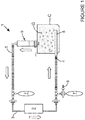
- an agitation apparatus 1 for providing fluid agitation inside a patient's body cavity C, said agitation apparatus 1 comprising at least a gas source (not shown); at least a pump 2; at least a tubing system 3, said tubing system 3 comprising at least an inlet tube 4 to deliver gas G into the patient's cavity and at least an outlet tube 5 to recover gas from the patient's cavity.
- Gas G for example carbon dioxide
- gas source (not shown) is introduced into the tubing system 3 of the agitation apparatus 1 via gas feeding port 6.
- the tubing system 3 is provided with one or more gas reservoirs, for example gas balloons 7, to increase the gas volume in the agitation apparatus 1.
- Pump 2 enables the circulation of gas G through the tubing system 3, in the direction as indicated by the arrows in figure 1 so that it is released into the patient's cavity through inlet tube 4.
- a segment of inlet tube 4 inserted in the patient's cavity C comprises a plurality of apertures 8 through gas G is released in the form of bubbles into the cavity.
- Any fluid F in the cavity is agitated due to the turbulence caused by the introduction of the gas bubbles and is homogenously distributed and administered to the target area.
- the agitation apparatus shown in figure 1 further comprises a gas-fluid separation device 9 intercalated between the patient's cavity and the outlet tube so that any fluid exiting the cavity together with the gas is removed before the gas re-enter the tubing system.
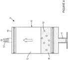
- a gas-fluid separation device 9 for separating fluid recovered from the patient's cavity from gas recovered from the patient's cavity is shown in figure 4 .
- This gas-fluid separation device 9 comprises a chamber 10 for receiving the gas-fluid mixture recovered from the patient's cavity.
- the chamber 10 is in the shape of a cylinder.
- the chamber 10 comprises a gas inlet port 11 for recovering the gas-fluid mixture from the patient's cavity and a gas outlet port 12 for extracting the gas from the chamber 10.
- the outlet port 12 is in gas communication with the outlet tube 5 and is located above fluid level in the top portion of the chamber 10. In this embodiment, the outlet port 12 is integrally formed with the chamber cap 16.
- the gas G exiting the gas-fluid separation device 9 is re-circulated into the agitation apparatus 1.
- the gas G could also be suitably discarded, although this alternative is only advised for small amounts of gas.
- Figure 5 shows a second gas-fluid separation device 9 further comprising a fluid outlet port 13 for extracting the fluid F from the chamber 10.
- the extracted fluid F can be discarded, as shown for example in figure 2 , or re-introduced into a fluid circulation system 14, as shown in figure 3 .
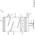
- Figure 6 shows a third gas-fluid separation device 9 in which the gas outlet port 12 is located on a side surface of the chamber 10, but could equally be integrally formed with the cap 16 as shown in figures 4 and 5 .
- the gas-fluid separation device 9 comprises means for facilitating the condensation of the fluid F recovered from the patient's cavity. Part of the therapeutic fluid F will be in a gas form, in particular if it has been heated prior to delivery into the patient's cavity, and will mix with the gas G from the agitation apparatus.
- the fluid F in a gas form will contact the condensation surfaces 15 and the inner surfaces of the chamber 10 and condensate back into a fluid form, thereby facilitating its separation from gas G.
- the condensation means can take any shape which will increase the inner surface area of the chamber 10, however the condensation surfaces15 shown in figure 6 are preferred in that the flat surface prevents the trapping of condensed fluid F, the slope facilitate the movement of the condensed fluid F towards the bottom of the chamber 10, and the design is simple, thereby simplifying the manufacture of the chamber 10.
- the condensation surface 15 is preferably attached to an inner wall of the chamber 10, may alternatively or additionally be attached to the base of the chamber 10 or to the cap 16 of the chamber 10.
- the angle between the condensation surface 15 and the surface to which it is attached is more than 0 degree and less than 90 degrees (or more than 90 degrees and less than 180 degrees).
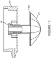
- Figures 7A to 7D and 8 to 10 depict a chamber base 17, a pin 18, a plug 19, a cover 20 and a filter 21 for use with securing means according to the present invention for securing the gas-fluid separation device to the patient.
- the base 17 of the chamber 10 is detachably connected (e.g. it can be screwed) to the bottom of the chamber 10, and a cap 16 is detachably connected to the top of the chamber 10.
- the chamber 10, the cap and/or the base 17 can be integrally formed.
- the pin 18, in use, is inserted into the patient through an opening and comprises a pin base 18A, and a hollow pin member 18B, in this embodiment a tubular pin extension with an inner channel 18D in fluid/gas communication with the patient's cavity, extending from the pin base 18A.
- the pin base 18A in this embodiment is a disk which lies flat against the patient's skin [fat layer?], and comprises an aperture 18C in fluid/gas communication with the patient's cavity.
- the pin member 18B extends through the patient's tissues and exits beyond the opening in the patient's skin.
- the pin 18 in this embodiment is integrally moulded and made of a flexible plastics material for ease of insertion.
- the pin extension 18B may be made of a flexible plastics material and the pin base 18A may be made of a material different from that of the pin extension 18B.
- the plug 19 comprises an inner channel 19A in fluid/gas communication with the patient's cavity.
- the outer dimensions of the plug 19 as such that when inserted into the inner channel 18D of the pin extension 18B, the walls of the pin extension 18B are pushed against the edges of an opening 17A in the base 17 of the chamber 10 to ensure seal and securing of the pin 18 to the chamber base 17 (see figure 8 ).
- the plug 19 comprises a ribbed outer surface 19C.
- the plug 19 comprises a peripheral rim 19B which sits on the end of the pin extension 18D.
- An optional cap 20 is provided for additional seal and protection of the parts extending into the chamber 10.
- the cap 20 partially surrounds those parts and comprises an opening 20A in fluid/gas connection with the patient's cavity.
- the cap 20 in this embodiment is a screw cap with inner screw thread 20B engaging with corresponding screw thread 17Bin the base 17 of the chamber 10 (see figure 9 ).
- the gas-fluid separationdevice 9 comprises means for preventing blockage of the inlet port 11 of the chamber 10 in the form of a bowl-shaped filter 21.
- the filter 21 is made for example of a mesh which prevents the patient's tissues or other bodies likely to block the passage of the fluid and gas out of the patient.
- the agitation apparatus 1 can also comprise additional filtration elements (not shown) to retain biologic or chemical elements and avoid contamination of the pumping element, the patient, and/or the environment.
- gas-fluid separation device 9 the primary function of gas-fluid separation device 9 is to separate fluid from gas exiting from the patient's cavity. Another important function of the gas-fluid separation device 9 is to act a visual indicator of the level of fluid in the patient, and therefore of the homogeneity of the distribution of the therapeutic fluid within the patient's cavity.
- the gas-fluid separation device 9 is placed on the patient's abdomen, most preferably at the uppermost region of the patient's abdomen.
- the therapeutic fluid is delivered into the patient's cavity and will fill gradually the cavity from the bottom of the cavity to the top of the cavity. As the fluid level reaches the top of the cavity, it will start rising into the gas-fluid separation device 9, thereby providing a visual indication that of the level of fluid within the cavity.
- the practitioner can adjust the delivery of the fluid accordingly in that no fluid in the gas-fluid separation device 9 will indicate the possible presence of an air pocket within the cavity (where the fluid will not be in contact with the patient's tissue and therefore not administered homogeneously) and the volume of fluid delivered to the cavity can be adjusted.
- the absence of fluid in the gas-fluid separation device 9 may also indicate a blockage of the inlet port 11 and the practitioner may unblock the port 11 or reposition the gas-fluid separation device 9 to prevent hindrance of the port 11 by the patient's tissues.
- a high level of fluid in the gas-fluid separation device might indicate an excess of fluid within the cavity, and to enable a uncontaminated separation of the gas from the fluid, the practitioner can adjust the volume of fluid delivered to the cavity.
- the inlet tube 4 comprises an on-line temperature sensor (not shown) to monitor the temperature of the gas G entering the cavity C, preferably in a segment of the tube 4 adjacent the point of entry into the patient for an accurate reading.
- the agitation apparatus 1 also comprises a temperature sensor (not shown) to monitor the temperature inside the patient's cavity.
- the outlet tube 5 comprises an on-line temperature sensor (not shown) to monitor the temperature of the gas exiting the patient's cavity. The temperature of the gas is adjusted using heating or cooling device (not shown) controlled with a temperature controller (not shown).
- the inlet tube 4 comprises an on-line flow and/or pressure sensor (not shown) to monitor the flow and/or pressure of the gas entering the cavity and the outlet tube 5 comprises an on-line flow and/or pressure sensor (not shown) to monitor the flow and/or pressure of the gas exiting the cavity.
- the flow and pressure of the gas is adjusted with a flow/pressure controller (not shown).
- the agitation apparatus 1 is used with a fluid delivery system (not shown), which only delivers the fluid to the patient's cavity.
- the fluid delivery system comprises a fluid source and a fluid inlet tube to deliver the fluid into the patient's cavity and optionally, a heating and/or cooling system and corresponding sensor(s) and controller and a pressure and/or flow controlling system.
- the fluid is extracted and separated using a gas-fluid separation device 9 described above.
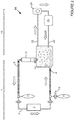
- the fluid circulation system 14 is a fluid delivery system which also allows the recovery of the fluid from the patient's cavity and the re-circulation of extracted fluid back into the patient's cavity.
- the fluid circulation system 14 comprises an inlet tube 22 to deliver the fluid into the patient's cavity, an outlet tube 23 to recover fluid from the patient's cavity, a pump 24 (e.g. a peristaltic pump) and a fluid heating/cooling device 25.
- the agitation apparatus 1 is combined with a fluid circulation system 14.
- the outlet tube 23 of the fluid circulation system 14 is connected to the fluid outlet port 13 of the gas-fluid separation device 9 of the agitation apparatus 1 so that the fluid F is recovered from the patient's cavity by the agitation apparatus, separated from the gas G in the gas-fluid separation device 9, and re-circulated through the fluid circulation system 14.
- the fluid agitation apparatus 1 is connected to the patient as follows.
- the gas inlet tube 4 is inserted into the patient and positioned adjacent the patient's cavity so that the apertures 8 of the inlet tube 4 are located adjacent the area to be treated.
- a small opening is made in the patient adjacent the cavity so that the gas-fluid separation device 9 can be fitted.
- the pin 18 is inserted in through the opening and positioned so that the pin base 18A lies flat against the patient's tissues and the pin extension 18B extends beyond the opening and the pin aperture 18C and channel 18D are in fluid/gas communication with the patient's cavity.
- the pin extension 18B engages the aperture 17A of the base 17 of the chamber 10 and further sealed and secured by inserting plug 19A into the channel 18D of the pin extension 18B.
- the cover 20 is screwed to the screw 17B of the chamber base 17 to partially surround and protect the pin 18 and plug 19.
- a therapeutic fluid F is introduced into the patient's cavity C through a fluid circulation system 14 and is circulated by means of a pump 24.
- the heating/cooling device 25 of the fluid circulation system 14 heats or cools the fluid F.
- the temperature of the fluid F is adjusted using a temperature controller (not shown) and measured by an on-line temperature sensor (not shown) before entry into the patient.
- the temperature sensor is arranged within the fluid inlet tube 22 and is located adjacent the point of entry into the patient so that an accurate reading is taken.
- a further temperature sensor (not shown) is located within the patient's cavity.
- the flow and pressure of the fluid F is adjusted using a flow and pressure controller (not shown).
- the pressure of the fluid F is measured by a pressure sensor (not shown) on or in the inlet tube 22.
- a gas G such as carbon dioxide
- the gas G can be heated or cooled and the temperature of the gas G can be adjusted using a temperature controller (not shown).
- the temperature of the gas G is measured by an on-line temperature sensor (not shown) before entry into the patient.
- the temperature sensor is arranged within the gas inlet tube 4 and is located adjacent the point of entry into the patient so that an accurate reading is taken.
- the flow and pressure of the gas G is adjusted using a flow and pressure controller (not shown).
- the pressure of the gas G is measured by a pressure sensor (not shown) on or in the gas inlet tube 4.
- the gas G is released into the patient's cavity C through apertures 8 in the form of bubbles so that turbulence is generated within the cavity C which will agitate the fluid F.
- the agitation ensures that the fluid F is homogeneously distributed throughout the cavity and administered to the areas to be treated.
- the fluid F can reach areas which are hidden in folds or behind organs and tissues which would normally hinder access to those areas.
- the gas G and fluid F is recovered from the patient's cavity using a gas-fluid separation device 9 as described above.
- the bowl-shaped filter 21 as shown in figure 10 prevents any tissues or other materials from entering or blocking the inlet port 11 of the gas-fluid separation device 9.
- the gas-fluid mixture enters the chamber 10 through the inlet port 11.
- the heavier fluid F deposits at the bottom of the chamber 10, while the lighter gas migrates towards the top of the chamber 10 above fluid level.
- the condensation of any fluid F in the form of gas is facilitated by the use of condensation surfaces as shown in figure 6 .
- the gas G is removed from the separation chamber 9 through gas outlet port 12 located either at the top or on the side wall of the chamber 10 and above the fluid level.
- the gas is re-introduced into the tubing system 3 via gas outlet tube 5, which connected to the outlet port 12.
- the temperature and pressure of the gas G is measured by one or more sensors arranged in or on the gas outlet tube 5.
- Gas reservoirs or balloons 7 are provided to increase the volume capacity of the agitation system 1 and avoid the use of great lengths of tubing.
- the fluid F is removed from the separation chamber 9 through fluid outlet port 13 located at the bottom of the chamber 10, either in the side wall of the chamber 10 or preferably in the base 17 of the chamber 10.
- the fluid F is re-introduced into the fluid circulation system 14 via fluid outlet tube 23.
- the temperature, flow and pressure of the fluid F exiting the chamber 10 is measured by one or more sensors arranged in or on the fluid outlet tube 23.
- the present invention provides a gas-fluid separation device for use with a fluid agitation apparatus used for the delivery and/or recirculation of therapeutic fluids.
- the agitation apparatus can be used for the delivery of heated therapeutic fluids to organs and/or body cavities, like peritoneum, but can also be used for the delivery of therapeutic fluids at different temperatures (cooled or heated) to this or other organs, such as the kidneys, colon, or the liver.
- the present invention is particularly advantageous in treatments requiring volumes of therapeutic fluid, for example with peritoneum chemo-hyperthermia, in that the agitation warranties the homogeneity of the distribution and of the temperature of the drug throughout the cavity.
Landscapes
- Health & Medical Sciences (AREA)
- Heart & Thoracic Surgery (AREA)
- Public Health (AREA)
- General Health & Medical Sciences (AREA)
- Veterinary Medicine (AREA)
- Engineering & Computer Science (AREA)
- Anesthesiology (AREA)
- Biomedical Technology (AREA)
- Hematology (AREA)
- Life Sciences & Earth Sciences (AREA)
- Animal Behavior & Ethology (AREA)
- Vascular Medicine (AREA)
- Urology & Nephrology (AREA)
- Emergency Medicine (AREA)
- Cardiology (AREA)
- Thermotherapy And Cooling Therapy Devices (AREA)
- Mixers With Rotating Receptacles And Mixers With Vibration Mechanisms (AREA)
- External Artificial Organs (AREA)
- Surgical Instruments (AREA)
Priority Applications (1)
| Application Number | Priority Date | Filing Date | Title |
|---|---|---|---|
| PL18196343T PL3434306T3 (pl) | 2012-11-12 | 2013-11-07 | Urządzenie do separacji gaz-płyn |
Applications Claiming Priority (3)
| Application Number | Priority Date | Filing Date | Title |
|---|---|---|---|
| GB1220306.3A GB2510321B (en) | 2012-11-12 | 2012-11-12 | Agitation apparatus |
| PCT/EP2013/073292 WO2014072423A2 (en) | 2012-11-12 | 2013-11-07 | Agitation apparatus |
| EP13789277.4A EP2916895B1 (en) | 2012-11-12 | 2013-11-07 | Agitation apparatus |
Related Parent Applications (2)
| Application Number | Title | Priority Date | Filing Date |
|---|---|---|---|
| EP13789277.4A Division-Into EP2916895B1 (en) | 2012-11-12 | 2013-11-07 | Agitation apparatus |
| EP13789277.4A Division EP2916895B1 (en) | 2012-11-12 | 2013-11-07 | Agitation apparatus |
Publications (3)
| Publication Number | Publication Date |
|---|---|
| EP3434306A2 EP3434306A2 (en) | 2019-01-30 |
| EP3434306A3 EP3434306A3 (en) | 2019-03-13 |
| EP3434306B1 true EP3434306B1 (en) | 2020-09-09 |
Family
ID=47470441
Family Applications (2)
| Application Number | Title | Priority Date | Filing Date |
|---|---|---|---|
| EP18196343.0A Active EP3434306B1 (en) | 2012-11-12 | 2013-11-07 | Gas-fluid separation device |
| EP13789277.4A Active EP2916895B1 (en) | 2012-11-12 | 2013-11-07 | Agitation apparatus |
Family Applications After (1)
| Application Number | Title | Priority Date | Filing Date |
|---|---|---|---|
| EP13789277.4A Active EP2916895B1 (en) | 2012-11-12 | 2013-11-07 | Agitation apparatus |
Country Status (9)
| Country | Link |
|---|---|
| US (1) | US10279132B2 (pl) |
| EP (2) | EP3434306B1 (pl) |
| JP (2) | JP6385353B2 (pl) |
| CA (2) | CA3077244C (pl) |
| DK (2) | DK2916895T3 (pl) |
| ES (2) | ES2834455T3 (pl) |
| GB (1) | GB2510321B (pl) |
| PL (2) | PL3434306T3 (pl) |
| WO (1) | WO2014072423A2 (pl) |
Families Citing this family (8)
| Publication number | Priority date | Publication date | Assignee | Title |
|---|---|---|---|---|
| GB201412842D0 (en) * | 2014-07-18 | 2014-09-03 | Combat Medical Sl | Catheter for the delivery of therapeutic fluid |
| KR20190108104A (ko) | 2016-12-31 | 2019-09-23 | 바이오엑셀 테라퓨틱스 인코포레이티드 | 불안의 치료를 위한 설하 덱스메데토미딘의 용도 |
| MX2020014000A (es) | 2018-06-27 | 2021-06-15 | Bioxcel Therapeutics Inc | Formulaciones en lámina que contienen dexmedetomidina y métodos para producirlas. |
| WO2020018567A1 (en) * | 2018-07-17 | 2020-01-23 | Theranova, Llc | Automated peritoneal organ support |
| JP2022540932A (ja) * | 2019-07-15 | 2022-09-20 | ソウル ナショナル ユニバーシティ ホスピタル | 腹腔内温熱加圧ガス循環システム及び二流体ノズルを含む腹腔内ガス提供システム |
| AU2020316013A1 (en) | 2019-07-19 | 2022-02-17 | Arx, Llc | Non-sedating dexmedetomidine treatment regimens |
| GB2590644B (en) * | 2019-12-20 | 2023-06-14 | Gamida Tech | Preparation and delivery of fluids for surgery |
| US11806334B1 (en) | 2023-01-12 | 2023-11-07 | Bioxcel Therapeutics, Inc. | Non-sedating dexmedetomidine treatment regimens |
Family Cites Families (42)
| Publication number | Priority date | Publication date | Assignee | Title |
|---|---|---|---|---|
| BE365554A (pl) | 1929-05-10 | 1929-12-31 | ||
| US3592191A (en) * | 1969-01-17 | 1971-07-13 | Richard R Jackson | Recovery of anesthetic agents |
| DE3121868A1 (de) | 1980-06-02 | 1982-03-11 | Henkin, Melvyn Lane, 91356 Tarzana, Calif. | Atemgeraet |
| US5643201A (en) * | 1984-07-09 | 1997-07-01 | Peabody; Alan M. | Continuous peritoneal dialysis apparatus |
| US4735603A (en) | 1986-09-10 | 1988-04-05 | James H. Goodson | Laser smoke evacuation system and method |
| US5388571A (en) * | 1987-07-17 | 1995-02-14 | Roberts; Josephine A. | Positive-pressure ventilator system with controlled access for nebulizer component servicing |
| JPH0382461A (ja) | 1989-08-25 | 1991-04-08 | Olympus Optical Co Ltd | 生体内結石の溶解装置 |
| WO1991014476A1 (en) * | 1990-03-22 | 1991-10-03 | Methodist Hospital Of Indiana, Inc. | Exhaled gas cooling device |
| US5814012A (en) * | 1992-03-16 | 1998-09-29 | Birtcher Medical Systems, Inc. | Method and apparatus for relieving excess insufflation pressure |
| AU3810593A (en) * | 1992-03-16 | 1993-10-21 | Birtcher Medical Systems, Inc. | Method and apparatus for relieving excess insufflation pressure |
| FR2705555A1 (fr) * | 1993-05-25 | 1994-12-02 | Fauck Denis | Appareil pour chirurgie cÓoelioscopique destiné à maintenir dans un pneumopéritoine une atmosphère propre et de volume constant. |
| BR9303188A (pt) | 1993-09-02 | 1995-04-25 | Celbras Quimica E Textil S A | Garrafa plástica para enchimento a quente |
| US6127525A (en) * | 1995-02-21 | 2000-10-03 | Cornell Research Foundation, Inc. | Chimeric adenoviral coat protein and methods of using same |
| US5849005A (en) * | 1995-06-07 | 1998-12-15 | Heartport, Inc. | Method and apparatus for minimizing the risk of air embolism when performing a procedure in a patient's thoracic cavity |
| EP1017434A4 (en) * | 1996-10-22 | 2000-08-30 | Renal Solutions Inc | CONTINUOUS FLOW PERITONEAL DIALYSIS (CFPD) PROCESS WITH REGULATION OF INTRAPERITONEAL PRESSURE |
| CN1294522A (zh) * | 1998-01-23 | 2001-05-09 | 赫莫特姆公司 | 用于全身高温治疗的装置和方法 |
| US7287398B2 (en) * | 2001-09-25 | 2007-10-30 | Alsius Corporation | Heating/cooling system for indwelling heat exchange catheter |
| US6673098B1 (en) * | 1998-08-24 | 2004-01-06 | Radiant Medical, Inc. | Disposable cassette for intravascular heat exchange catheter |
| DE19900712C1 (de) | 1998-09-23 | 2000-08-03 | Adeva Medical Ges Fuer Entwick | Tracheostoma-Ventil |
| US6544210B1 (en) | 1998-10-22 | 2003-04-08 | Gregory J. Trudel | Disposable laparoscopic smoke evacuation system |
| JP2000202022A (ja) | 1999-01-12 | 2000-07-25 | Jms Co Ltd | 医療用排液処理装置 |
| US7001380B2 (en) * | 1999-01-15 | 2006-02-21 | Gyrus Medical Limited | Electrosurgical system and method |
| JP2000296146A (ja) | 1999-04-16 | 2000-10-24 | Olympus Optical Co Ltd | 腹腔内灌流加温装置 |
| JP2000300666A (ja) * | 1999-04-23 | 2000-10-31 | Olympus Optical Co Ltd | 腹腔内灌流加温装置 |
| US7238164B2 (en) | 2002-07-19 | 2007-07-03 | Baxter International Inc. | Systems, methods and apparatuses for pumping cassette-based therapies |
| US7854724B2 (en) * | 2003-04-08 | 2010-12-21 | Surgiquest, Inc. | Trocar assembly with pneumatic sealing |
| DE202004021703U1 (de) * | 2003-10-07 | 2010-05-27 | Northgate Technologies Inc., Elgin | Vorrichtung zur Abgabe einer Substanz in eine Körperhöhle |
| SE0302698L (sv) * | 2003-10-13 | 2005-04-14 | Gambro Lundia Ab | Anordning för genomförande av en peritonealdialys -behandling |
| US20070093697A1 (en) * | 2005-10-21 | 2007-04-26 | Theranova, Llc | Method and apparatus for detection of right to left shunting in the cardiopulmonary vasculature |
| ATE498364T1 (de) * | 2006-09-08 | 2011-03-15 | Surgiquest Inc | Trokaranordnung mit pneumatischem verschluss |
| US20080097562A1 (en) * | 2006-10-19 | 2008-04-24 | Dyamed Biotech Pte Ltd | System For Chemohyperthermia Treatment |
| US7892331B2 (en) | 2007-10-01 | 2011-02-22 | Baxter International Inc. | Dialysis systems having air separation chambers with internal structures to enhance air removal |
| US7871462B2 (en) * | 2007-10-01 | 2011-01-18 | Baxter International Inc. | Dialysis systems having air separation chambers with internal structures to enhance air removal |
| US7892332B2 (en) | 2007-10-01 | 2011-02-22 | Baxter International Inc. | Dialysis systems having air traps with internal structures to enhance air removal |
| US8475389B2 (en) * | 2008-02-19 | 2013-07-02 | Portaero, Inc. | Methods and devices for assessment of pneumostoma function |
| EP2242527A4 (en) * | 2008-02-19 | 2011-07-13 | Portaero Inc | DEVICES AND METHOD FOR THE DELIVERY OF A THERAPEUTIC AGENT BY A PNEUMOSTOMA |
| JP2012502672A (ja) | 2008-09-17 | 2012-02-02 | レスメド・リミテッド | Cpap装置用ディスプレイ及びコントローラ |
| CN102264310B (zh) * | 2008-10-10 | 2014-01-22 | 瑟吉奎斯特公司 | 用于具有气动密封的手术套针内的改善的气体再循环的系统和方法 |
| US8791315B2 (en) * | 2010-02-26 | 2014-07-29 | Smith & Nephew, Inc. | Systems and methods for using negative pressure wound therapy to manage open abdominal wounds |
| US8905019B2 (en) | 2010-05-11 | 2014-12-09 | Carefusion 207, Inc. | Patient circuit integrity alarm using exhaled CO2 |
| EP2618909A4 (en) * | 2010-09-20 | 2014-06-18 | Surgiquest Inc | FILTRATION SYSTEM WITH MULTIPLE FLOWS |
| GB201021898D0 (en) * | 2010-12-23 | 2011-02-02 | Albalat Alberto M | Fluid circulation system |
-
2012
- 2012-11-12 GB GB1220306.3A patent/GB2510321B/en active Active
-
2013
- 2013-11-07 PL PL18196343T patent/PL3434306T3/pl unknown
- 2013-11-07 DK DK13789277.4T patent/DK2916895T3/da active
- 2013-11-07 EP EP18196343.0A patent/EP3434306B1/en active Active
- 2013-11-07 DK DK18196343.0T patent/DK3434306T3/da active
- 2013-11-07 ES ES18196343T patent/ES2834455T3/es active Active
- 2013-11-07 WO PCT/EP2013/073292 patent/WO2014072423A2/en not_active Ceased
- 2013-11-07 JP JP2015541135A patent/JP6385353B2/ja active Active
- 2013-11-07 EP EP13789277.4A patent/EP2916895B1/en active Active
- 2013-11-07 ES ES13789277T patent/ES2742032T3/es active Active
- 2013-11-07 CA CA3077244A patent/CA3077244C/en active Active
- 2013-11-07 US US14/435,202 patent/US10279132B2/en active Active
- 2013-11-07 PL PL13789277T patent/PL2916895T3/pl unknown
- 2013-11-07 CA CA2889371A patent/CA2889371C/en active Active
-
2018
- 2018-08-07 JP JP2018148417A patent/JP6553784B2/ja active Active
Non-Patent Citations (1)
| Title |
|---|
| None * |
Also Published As
| Publication number | Publication date |
|---|---|
| EP2916895B1 (en) | 2019-05-22 |
| CA2889371C (en) | 2021-01-12 |
| GB2510321B (en) | 2018-01-31 |
| US10279132B2 (en) | 2019-05-07 |
| GB201220306D0 (en) | 2012-12-26 |
| WO2014072423A3 (en) | 2014-07-31 |
| JP6553784B2 (ja) | 2019-07-31 |
| US20150250957A1 (en) | 2015-09-10 |
| GB2510321A (en) | 2014-08-06 |
| JP6385353B2 (ja) | 2018-09-05 |
| CA3077244A1 (en) | 2014-05-15 |
| EP3434306A2 (en) | 2019-01-30 |
| PL3434306T3 (pl) | 2021-03-08 |
| DK2916895T3 (da) | 2019-08-26 |
| DK3434306T3 (da) | 2020-12-07 |
| EP3434306A3 (en) | 2019-03-13 |
| JP2015533594A (ja) | 2015-11-26 |
| JP2018164857A (ja) | 2018-10-25 |
| ES2834455T3 (es) | 2021-06-17 |
| CA3077244C (en) | 2022-03-15 |
| PL2916895T3 (pl) | 2019-12-31 |
| WO2014072423A2 (en) | 2014-05-15 |
| CA2889371A1 (en) | 2014-05-15 |
| ES2742032T3 (es) | 2020-02-12 |
| EP2916895A2 (en) | 2015-09-16 |
Similar Documents
| Publication | Publication Date | Title |
|---|---|---|
| EP3434306B1 (en) | Gas-fluid separation device | |
| US20100004595A1 (en) | Balloon catheter systems for treating uterine disorders having fluid line de-gassing assemblies and methods therefor | |
| US20080234619A1 (en) | Portable Hyperthermia Apparatus | |
| EP2654861B1 (en) | Fluid circulation system | |
| AU2017259117B2 (en) | Recirculating cooling systems for use with energy delivery devices | |
| US20190192792A1 (en) | Agitation apparatus | |
| GB2553460A (en) | Agitation apparatus | |
| HK1245688A1 (en) | Gas-fluid separation device | |
| HK1245688A (en) | Gas-fluid separation device | |
| US20120109267A1 (en) | Heating system for a hyperthermia apparatus | |
| ES3035512T3 (en) | Preparation and delivery of fluids for surgery |
Legal Events
| Date | Code | Title | Description |
|---|---|---|---|
| PUAI | Public reference made under article 153(3) epc to a published international application that has entered the european phase |
Free format text: ORIGINAL CODE: 0009012 |
|
| STAA | Information on the status of an ep patent application or granted ep patent |
Free format text: STATUS: THE APPLICATION HAS BEEN PUBLISHED |
|
| AC | Divisional application: reference to earlier application |
Ref document number: 2916895 Country of ref document: EP Kind code of ref document: P |
|
| AK | Designated contracting states |
Kind code of ref document: A2 Designated state(s): AL AT BE BG CH CY CZ DE DK EE ES FI FR GB GR HR HU IE IS IT LI LT LU LV MC MK MT NL NO PL PT RO RS SE SI SK SM TR |
|
| PUAL | Search report despatched |
Free format text: ORIGINAL CODE: 0009013 |
|
| AK | Designated contracting states |
Kind code of ref document: A3 Designated state(s): AL AT BE BG CH CY CZ DE DK EE ES FI FR GB GR HR HU IE IS IT LI LT LU LV MC MK MT NL NO PL PT RO RS SE SI SK SM TR |
|
| RIC1 | Information provided on ipc code assigned before grant |
Ipc: A61M 16/10 20060101ALN20190201BHEP Ipc: A61M 13/00 20060101AFI20190201BHEP Ipc: A61M 16/16 20060101ALN20190201BHEP Ipc: A61M 1/28 20060101ALI20190201BHEP Ipc: A61M 1/36 20060101ALI20190201BHEP |
|
| STAA | Information on the status of an ep patent application or granted ep patent |
Free format text: STATUS: REQUEST FOR EXAMINATION WAS MADE |
|
| 17P | Request for examination filed |
Effective date: 20190905 |
|
| RBV | Designated contracting states (corrected) |
Designated state(s): AL AT BE BG CH CY CZ DE DK EE ES FI FR GB GR HR HU IE IS IT LI LT LU LV MC MK MT NL NO PL PT RO RS SE SI SK SM TR |
|
| STAA | Information on the status of an ep patent application or granted ep patent |
Free format text: STATUS: EXAMINATION IS IN PROGRESS |
|
| 17Q | First examination report despatched |
Effective date: 20200116 |
|
| GRAP | Despatch of communication of intention to grant a patent |
Free format text: ORIGINAL CODE: EPIDOSNIGR1 |
|
| STAA | Information on the status of an ep patent application or granted ep patent |
Free format text: STATUS: GRANT OF PATENT IS INTENDED |
|
| RIC1 | Information provided on ipc code assigned before grant |
Ipc: A61M 13/00 20060101AFI20200302BHEP Ipc: A61M 1/36 20060101ALI20200302BHEP Ipc: A61M 16/10 20060101ALN20200302BHEP Ipc: A61M 1/28 20060101ALI20200302BHEP Ipc: A61M 16/16 20060101ALN20200302BHEP |
|
| RIC1 | Information provided on ipc code assigned before grant |
Ipc: A61M 1/36 20060101ALI20200312BHEP Ipc: A61M 13/00 20060101AFI20200312BHEP Ipc: A61M 16/10 20060101ALN20200312BHEP Ipc: A61M 16/16 20060101ALN20200312BHEP Ipc: A61M 1/28 20060101ALI20200312BHEP |
|
| INTG | Intention to grant announced |
Effective date: 20200324 |
|
| GRAS | Grant fee paid |
Free format text: ORIGINAL CODE: EPIDOSNIGR3 |
|
| GRAA | (expected) grant |
Free format text: ORIGINAL CODE: 0009210 |
|
| STAA | Information on the status of an ep patent application or granted ep patent |
Free format text: STATUS: THE PATENT HAS BEEN GRANTED |
|
| AC | Divisional application: reference to earlier application |
Ref document number: 2916895 Country of ref document: EP Kind code of ref document: P |
|
| AK | Designated contracting states |
Kind code of ref document: B1 Designated state(s): AL AT BE BG CH CY CZ DE DK EE ES FI FR GB GR HR HU IE IS IT LI LT LU LV MC MK MT NL NO PL PT RO RS SE SI SK SM TR |
|
| REG | Reference to a national code |
Ref country code: GB Ref legal event code: FG4D |
|
| REG | Reference to a national code |
Ref country code: AT Ref legal event code: REF Ref document number: 1310774 Country of ref document: AT Kind code of ref document: T Effective date: 20200915 Ref country code: CH Ref legal event code: EP |
|
| REG | Reference to a national code |
Ref country code: DE Ref legal event code: R096 Ref document number: 602013072506 Country of ref document: DE |
|
| REG | Reference to a national code |
Ref country code: IE Ref legal event code: FG4D |
|
| REG | Reference to a national code |
Ref country code: NL Ref legal event code: FP |
|
| REG | Reference to a national code |
Ref country code: SE Ref legal event code: TRGR |
|
| REG | Reference to a national code |
Ref country code: DK Ref legal event code: T3 Effective date: 20201203 |
|
| REG | Reference to a national code |
Ref country code: LT Ref legal event code: MG4D |
|
| PG25 | Lapsed in a contracting state [announced via postgrant information from national office to epo] |
Ref country code: LT Free format text: LAPSE BECAUSE OF FAILURE TO SUBMIT A TRANSLATION OF THE DESCRIPTION OR TO PAY THE FEE WITHIN THE PRESCRIBED TIME-LIMIT Effective date: 20200909 Ref country code: HR Free format text: LAPSE BECAUSE OF FAILURE TO SUBMIT A TRANSLATION OF THE DESCRIPTION OR TO PAY THE FEE WITHIN THE PRESCRIBED TIME-LIMIT Effective date: 20200909 Ref country code: BG Free format text: LAPSE BECAUSE OF FAILURE TO SUBMIT A TRANSLATION OF THE DESCRIPTION OR TO PAY THE FEE WITHIN THE PRESCRIBED TIME-LIMIT Effective date: 20201209 Ref country code: FI Free format text: LAPSE BECAUSE OF FAILURE TO SUBMIT A TRANSLATION OF THE DESCRIPTION OR TO PAY THE FEE WITHIN THE PRESCRIBED TIME-LIMIT Effective date: 20200909 Ref country code: GR Free format text: LAPSE BECAUSE OF FAILURE TO SUBMIT A TRANSLATION OF THE DESCRIPTION OR TO PAY THE FEE WITHIN THE PRESCRIBED TIME-LIMIT Effective date: 20201210 |
|
| REG | Reference to a national code |
Ref country code: AT Ref legal event code: MK05 Ref document number: 1310774 Country of ref document: AT Kind code of ref document: T Effective date: 20200909 Ref country code: NO Ref legal event code: T2 Effective date: 20200909 |
|
| PG25 | Lapsed in a contracting state [announced via postgrant information from national office to epo] |
Ref country code: RS Free format text: LAPSE BECAUSE OF FAILURE TO SUBMIT A TRANSLATION OF THE DESCRIPTION OR TO PAY THE FEE WITHIN THE PRESCRIBED TIME-LIMIT Effective date: 20200909 Ref country code: LV Free format text: LAPSE BECAUSE OF FAILURE TO SUBMIT A TRANSLATION OF THE DESCRIPTION OR TO PAY THE FEE WITHIN THE PRESCRIBED TIME-LIMIT Effective date: 20200909 |
|
| PG25 | Lapsed in a contracting state [announced via postgrant information from national office to epo] |
Ref country code: SM Free format text: LAPSE BECAUSE OF FAILURE TO SUBMIT A TRANSLATION OF THE DESCRIPTION OR TO PAY THE FEE WITHIN THE PRESCRIBED TIME-LIMIT Effective date: 20200909 Ref country code: EE Free format text: LAPSE BECAUSE OF FAILURE TO SUBMIT A TRANSLATION OF THE DESCRIPTION OR TO PAY THE FEE WITHIN THE PRESCRIBED TIME-LIMIT Effective date: 20200909 Ref country code: RO Free format text: LAPSE BECAUSE OF FAILURE TO SUBMIT A TRANSLATION OF THE DESCRIPTION OR TO PAY THE FEE WITHIN THE PRESCRIBED TIME-LIMIT Effective date: 20200909 Ref country code: PT Free format text: LAPSE BECAUSE OF FAILURE TO SUBMIT A TRANSLATION OF THE DESCRIPTION OR TO PAY THE FEE WITHIN THE PRESCRIBED TIME-LIMIT Effective date: 20210111 Ref country code: CZ Free format text: LAPSE BECAUSE OF FAILURE TO SUBMIT A TRANSLATION OF THE DESCRIPTION OR TO PAY THE FEE WITHIN THE PRESCRIBED TIME-LIMIT Effective date: 20200909 |
|
| PG25 | Lapsed in a contracting state [announced via postgrant information from national office to epo] |
Ref country code: IS Free format text: LAPSE BECAUSE OF FAILURE TO SUBMIT A TRANSLATION OF THE DESCRIPTION OR TO PAY THE FEE WITHIN THE PRESCRIBED TIME-LIMIT Effective date: 20210109 Ref country code: AL Free format text: LAPSE BECAUSE OF FAILURE TO SUBMIT A TRANSLATION OF THE DESCRIPTION OR TO PAY THE FEE WITHIN THE PRESCRIBED TIME-LIMIT Effective date: 20200909 Ref country code: AT Free format text: LAPSE BECAUSE OF FAILURE TO SUBMIT A TRANSLATION OF THE DESCRIPTION OR TO PAY THE FEE WITHIN THE PRESCRIBED TIME-LIMIT Effective date: 20200909 |
|
| REG | Reference to a national code |
Ref country code: DE Ref legal event code: R097 Ref document number: 602013072506 Country of ref document: DE |
|
| REG | Reference to a national code |
Ref country code: ES Ref legal event code: FG2A Ref document number: 2834455 Country of ref document: ES Kind code of ref document: T3 Effective date: 20210617 |
|
| PG25 | Lapsed in a contracting state [announced via postgrant information from national office to epo] |
Ref country code: MC Free format text: LAPSE BECAUSE OF FAILURE TO SUBMIT A TRANSLATION OF THE DESCRIPTION OR TO PAY THE FEE WITHIN THE PRESCRIBED TIME-LIMIT Effective date: 20200909 Ref country code: SK Free format text: LAPSE BECAUSE OF FAILURE TO SUBMIT A TRANSLATION OF THE DESCRIPTION OR TO PAY THE FEE WITHIN THE PRESCRIBED TIME-LIMIT Effective date: 20200909 |
|
| REG | Reference to a national code |
Ref country code: CH Ref legal event code: PL |
|
| PLBE | No opposition filed within time limit |
Free format text: ORIGINAL CODE: 0009261 |
|
| STAA | Information on the status of an ep patent application or granted ep patent |
Free format text: STATUS: NO OPPOSITION FILED WITHIN TIME LIMIT |
|
| PG25 | Lapsed in a contracting state [announced via postgrant information from national office to epo] |
Ref country code: LU Free format text: LAPSE BECAUSE OF NON-PAYMENT OF DUE FEES Effective date: 20201107 |
|
| REG | Reference to a national code |
Ref country code: BE Ref legal event code: MM Effective date: 20201130 |
|
| 26N | No opposition filed |
Effective date: 20210610 |
|
| PG25 | Lapsed in a contracting state [announced via postgrant information from national office to epo] |
Ref country code: SI Free format text: LAPSE BECAUSE OF FAILURE TO SUBMIT A TRANSLATION OF THE DESCRIPTION OR TO PAY THE FEE WITHIN THE PRESCRIBED TIME-LIMIT Effective date: 20200909 Ref country code: LI Free format text: LAPSE BECAUSE OF NON-PAYMENT OF DUE FEES Effective date: 20201130 Ref country code: CH Free format text: LAPSE BECAUSE OF NON-PAYMENT OF DUE FEES Effective date: 20201130 |
|
| PG25 | Lapsed in a contracting state [announced via postgrant information from national office to epo] |
Ref country code: MT Free format text: LAPSE BECAUSE OF FAILURE TO SUBMIT A TRANSLATION OF THE DESCRIPTION OR TO PAY THE FEE WITHIN THE PRESCRIBED TIME-LIMIT Effective date: 20200909 Ref country code: CY Free format text: LAPSE BECAUSE OF FAILURE TO SUBMIT A TRANSLATION OF THE DESCRIPTION OR TO PAY THE FEE WITHIN THE PRESCRIBED TIME-LIMIT Effective date: 20200909 |
|
| PG25 | Lapsed in a contracting state [announced via postgrant information from national office to epo] |
Ref country code: MK Free format text: LAPSE BECAUSE OF FAILURE TO SUBMIT A TRANSLATION OF THE DESCRIPTION OR TO PAY THE FEE WITHIN THE PRESCRIBED TIME-LIMIT Effective date: 20200909 |
|
| PG25 | Lapsed in a contracting state [announced via postgrant information from national office to epo] |
Ref country code: BE Free format text: LAPSE BECAUSE OF NON-PAYMENT OF DUE FEES Effective date: 20201130 |
|
| PGFP | Annual fee paid to national office [announced via postgrant information from national office to epo] |
Ref country code: PL Payment date: 20250916 Year of fee payment: 13 Ref country code: NL Payment date: 20250912 Year of fee payment: 13 |
|
| PGFP | Annual fee paid to national office [announced via postgrant information from national office to epo] |
Ref country code: GB Payment date: 20250918 Year of fee payment: 13 |
|
| PGFP | Annual fee paid to national office [announced via postgrant information from national office to epo] |
Ref country code: FR Payment date: 20250908 Year of fee payment: 13 |
|
| PGFP | Annual fee paid to national office [announced via postgrant information from national office to epo] |
Ref country code: SE Payment date: 20250910 Year of fee payment: 13 |
|
| PGFP | Annual fee paid to national office [announced via postgrant information from national office to epo] |
Ref country code: IE Payment date: 20250909 Year of fee payment: 13 |
|
| PGFP | Annual fee paid to national office [announced via postgrant information from national office to epo] |
Ref country code: DE Payment date: 20250910 Year of fee payment: 13 |
|
| PGFP | Annual fee paid to national office [announced via postgrant information from national office to epo] |
Ref country code: NO Payment date: 20251113 Year of fee payment: 13 |
|
| PGFP | Annual fee paid to national office [announced via postgrant information from national office to epo] |
Ref country code: DK Payment date: 20251112 Year of fee payment: 13 Ref country code: IT Payment date: 20251022 Year of fee payment: 13 |
|
| PGFP | Annual fee paid to national office [announced via postgrant information from national office to epo] |
Ref country code: TR Payment date: 20251031 Year of fee payment: 13 |
|
| PGFP | Annual fee paid to national office [announced via postgrant information from national office to epo] |
Ref country code: ES Payment date: 20251212 Year of fee payment: 13 |