EP3433684B1 - Vorrichtung und verfahren zum konfigurieren einer multivalenten energieversorgungsanlage - Google Patents
Vorrichtung und verfahren zum konfigurieren einer multivalenten energieversorgungsanlage Download PDFInfo
- Publication number
- EP3433684B1 EP3433684B1 EP17713249.5A EP17713249A EP3433684B1 EP 3433684 B1 EP3433684 B1 EP 3433684B1 EP 17713249 A EP17713249 A EP 17713249A EP 3433684 B1 EP3433684 B1 EP 3433684B1
- Authority
- EP
- European Patent Office
- Prior art keywords
- energy
- flow
- buffer storage
- base configuration
- generators
- Prior art date
- Legal status (The legal status is an assumption and is not a legal conclusion. Google has not performed a legal analysis and makes no representation as to the accuracy of the status listed.)
- Active
Links
Images


Classifications
-
- F—MECHANICAL ENGINEERING; LIGHTING; HEATING; WEAPONS; BLASTING
- F24—HEATING; RANGES; VENTILATING
- F24D—DOMESTIC- OR SPACE-HEATING SYSTEMS, e.g. CENTRAL HEATING SYSTEMS; DOMESTIC HOT-WATER SUPPLY SYSTEMS; ELEMENTS OR COMPONENTS THEREFOR
- F24D19/00—Details
- F24D19/10—Arrangement or mounting of control or safety devices
-
- F—MECHANICAL ENGINEERING; LIGHTING; HEATING; WEAPONS; BLASTING
- F24—HEATING; RANGES; VENTILATING
- F24D—DOMESTIC- OR SPACE-HEATING SYSTEMS, e.g. CENTRAL HEATING SYSTEMS; DOMESTIC HOT-WATER SUPPLY SYSTEMS; ELEMENTS OR COMPONENTS THEREFOR
- F24D11/00—Central heating systems using heat accumulated in storage masses
- F24D11/002—Central heating systems using heat accumulated in storage masses water heating system
-
- F—MECHANICAL ENGINEERING; LIGHTING; HEATING; WEAPONS; BLASTING
- F24—HEATING; RANGES; VENTILATING
- F24D—DOMESTIC- OR SPACE-HEATING SYSTEMS, e.g. CENTRAL HEATING SYSTEMS; DOMESTIC HOT-WATER SUPPLY SYSTEMS; ELEMENTS OR COMPONENTS THEREFOR
- F24D12/00—Other central heating systems
- F24D12/02—Other central heating systems having more than one heat source
-
- F—MECHANICAL ENGINEERING; LIGHTING; HEATING; WEAPONS; BLASTING
- F24—HEATING; RANGES; VENTILATING
- F24D—DOMESTIC- OR SPACE-HEATING SYSTEMS, e.g. CENTRAL HEATING SYSTEMS; DOMESTIC HOT-WATER SUPPLY SYSTEMS; ELEMENTS OR COMPONENTS THEREFOR
- F24D17/00—Domestic hot-water supply systems
- F24D17/0036—Domestic hot-water supply systems with combination of different kinds of heating means
-
- F—MECHANICAL ENGINEERING; LIGHTING; HEATING; WEAPONS; BLASTING
- F24—HEATING; RANGES; VENTILATING
- F24H—FLUID HEATERS, e.g. WATER OR AIR HEATERS, HAVING HEAT-GENERATING MEANS, e.g. HEAT PUMPS, IN GENERAL
- F24H9/00—Details
- F24H9/14—Arrangements for connecting different sections, e.g. in water heaters
- F24H9/148—Arrangements of boiler components on a frame or within a casing to build the fluid heater, e.g. boiler
-
- G—PHYSICS
- G05—CONTROLLING; REGULATING
- G05B—CONTROL OR REGULATING SYSTEMS IN GENERAL; FUNCTIONAL ELEMENTS OF SUCH SYSTEMS; MONITORING OR TESTING ARRANGEMENTS FOR SUCH SYSTEMS OR ELEMENTS
- G05B19/00—Program-control systems
- G05B19/02—Program-control systems electric
- G05B19/04—Program control other than numerical control, i.e. in sequence controllers or logic controllers
- G05B19/042—Program control other than numerical control, i.e. in sequence controllers or logic controllers using digital processors
-
- F—MECHANICAL ENGINEERING; LIGHTING; HEATING; WEAPONS; BLASTING
- F24—HEATING; RANGES; VENTILATING
- F24D—DOMESTIC- OR SPACE-HEATING SYSTEMS, e.g. CENTRAL HEATING SYSTEMS; DOMESTIC HOT-WATER SUPPLY SYSTEMS; ELEMENTS OR COMPONENTS THEREFOR
- F24D2200/00—Heat sources or energy sources
- F24D2200/04—Gas or oil fired boiler
-
- F—MECHANICAL ENGINEERING; LIGHTING; HEATING; WEAPONS; BLASTING
- F24—HEATING; RANGES; VENTILATING
- F24D—DOMESTIC- OR SPACE-HEATING SYSTEMS, e.g. CENTRAL HEATING SYSTEMS; DOMESTIC HOT-WATER SUPPLY SYSTEMS; ELEMENTS OR COMPONENTS THEREFOR
- F24D2200/00—Heat sources or energy sources
- F24D2200/08—Electric heater
-
- F—MECHANICAL ENGINEERING; LIGHTING; HEATING; WEAPONS; BLASTING
- F24—HEATING; RANGES; VENTILATING
- F24D—DOMESTIC- OR SPACE-HEATING SYSTEMS, e.g. CENTRAL HEATING SYSTEMS; DOMESTIC HOT-WATER SUPPLY SYSTEMS; ELEMENTS OR COMPONENTS THEREFOR
- F24D2200/00—Heat sources or energy sources
- F24D2200/32—Heat sources or energy sources involving multiple heat sources in combination or as alternative heat sources
-
- G—PHYSICS
- G05—CONTROLLING; REGULATING
- G05B—CONTROL OR REGULATING SYSTEMS IN GENERAL; FUNCTIONAL ELEMENTS OF SUCH SYSTEMS; MONITORING OR TESTING ARRANGEMENTS FOR SUCH SYSTEMS OR ELEMENTS
- G05B2219/00—Program-control systems
- G05B2219/20—Pc systems
- G05B2219/26—Pc applications
- G05B2219/2614—HVAC, heating, ventillation, climate control
-
- H—ELECTRICITY
- H02—GENERATION; CONVERSION OR DISTRIBUTION OF ELECTRIC POWER
- H02J—ELECTRIC POWER NETWORKS; CIRCUIT ARRANGEMENTS OR SYSTEMS FOR SUPPLYING OR DISTRIBUTING ELECTRIC POWER; SYSTEMS FOR STORING ELECTRIC ENERGY
- H02J3/00—Circuit arrangements for AC mains or AC distribution networks
- H02J3/28—Arrangements for balancing of the load in networks by storage of energy
- H02J3/32—Arrangements for balancing of the load in networks by storage of energy using batteries or super capacitors with converting means
-
- H—ELECTRICITY
- H02—GENERATION; CONVERSION OR DISTRIBUTION OF ELECTRIC POWER
- H02J—ELECTRIC POWER NETWORKS; CIRCUIT ARRANGEMENTS OR SYSTEMS FOR SUPPLYING OR DISTRIBUTING ELECTRIC POWER; SYSTEMS FOR STORING ELECTRIC ENERGY
- H02J3/00—Circuit arrangements for AC mains or AC distribution networks
- H02J3/38—Arrangements for feeding a single network from two or more generators or sources in parallel; Arrangements for feeding already energised networks from additional generators or sources in parallel
- H02J3/381—Dispersed generators
-
- Y—GENERAL TAGGING OF NEW TECHNOLOGICAL DEVELOPMENTS; GENERAL TAGGING OF CROSS-SECTIONAL TECHNOLOGIES SPANNING OVER SEVERAL SECTIONS OF THE IPC; TECHNICAL SUBJECTS COVERED BY FORMER USPC CROSS-REFERENCE ART COLLECTIONS [XRACs] AND DIGESTS
- Y02—TECHNOLOGIES OR APPLICATIONS FOR MITIGATION OR ADAPTATION AGAINST CLIMATE CHANGE
- Y02B—CLIMATE CHANGE MITIGATION TECHNOLOGIES RELATED TO BUILDINGS, e.g. HOUSING, HOUSE APPLIANCES OR RELATED END-USER APPLICATIONS
- Y02B10/00—Integration of renewable energy sources in buildings
- Y02B10/20—Solar thermal
-
- Y—GENERAL TAGGING OF NEW TECHNOLOGICAL DEVELOPMENTS; GENERAL TAGGING OF CROSS-SECTIONAL TECHNOLOGIES SPANNING OVER SEVERAL SECTIONS OF THE IPC; TECHNICAL SUBJECTS COVERED BY FORMER USPC CROSS-REFERENCE ART COLLECTIONS [XRACs] AND DIGESTS
- Y02—TECHNOLOGIES OR APPLICATIONS FOR MITIGATION OR ADAPTATION AGAINST CLIMATE CHANGE
- Y02B—CLIMATE CHANGE MITIGATION TECHNOLOGIES RELATED TO BUILDINGS, e.g. HOUSING, HOUSE APPLIANCES OR RELATED END-USER APPLICATIONS
- Y02B10/00—Integration of renewable energy sources in buildings
- Y02B10/70—Hybrid systems, e.g. uninterruptible or back-up power supplies integrating renewable energies
-
- Y—GENERAL TAGGING OF NEW TECHNOLOGICAL DEVELOPMENTS; GENERAL TAGGING OF CROSS-SECTIONAL TECHNOLOGIES SPANNING OVER SEVERAL SECTIONS OF THE IPC; TECHNICAL SUBJECTS COVERED BY FORMER USPC CROSS-REFERENCE ART COLLECTIONS [XRACs] AND DIGESTS
- Y02—TECHNOLOGIES OR APPLICATIONS FOR MITIGATION OR ADAPTATION AGAINST CLIMATE CHANGE
- Y02B—CLIMATE CHANGE MITIGATION TECHNOLOGIES RELATED TO BUILDINGS, e.g. HOUSING, HOUSE APPLIANCES OR RELATED END-USER APPLICATIONS
- Y02B30/00—Energy efficient heating, ventilation or air conditioning [HVAC]
Definitions
- the present invention relates to an arrangement comprising a device for configuring a multivalent energy generation system and a control device and a method for configuring a multivalent energy supply system.
- a method for operating a system with a plurality of heat generating devices is, for example, from US Pat EP 2187136 A2 known.
- the system can provide heat output using a plurality of heat generation devices, the distribution of the heat output to the individual heat generation devices being variable, so that they can be operated close to their optimal efficiency.
- the allocation of power can not only take place via a higher-level boiler management system, but also by coordinating the individual heat generation devices with one another.
- a mobile heating system which has a plurality of fuel-operated heating devices which are in communication with one another via a bus system.
- the heating system is set up in such a way that when the heating system is started, based on predetermined rules, one of the heating devices is configured as a master with regard to the control of further heating devices connected to the bus system.
- the remaining heaters are configured as slaves.
- a hybrid heating system consisting of at least one condensing boiler and at least one non-condensing boiler is from the international patent application WO 2008/091970 A2 known.
- the switching on and off of the individual boilers by a control takes place after the heating load has been determined, among other things on the basis of the flow in the main line of the heating system and other start criteria.
- the boiler is also selected depending on the outside temperature and the operating hours of the individual boilers.
- the US patent application US 2007/038321 A1 discloses a method for simulating an industrial plant.
- the method includes creating a library of industrial plant component types using user input.
- the library contains properties of the component types and rules for generating scripts according to the property values.
- the method further comprises compiling a configuration of industrial plant components from the library using user input.
- the configuration is combined into an editor which is configured in such a way that it accepts a layout and a connection of the configuration of industrial plant components and a configuration and setting of the properties of the industrial plant components.
- German patent application DE 10348563 A1 Process plants and, in particular, an intelligent control and simulation environment are known which allow the user to integrate viewing, simulation and control at the system level of the process plant control architecture.
- the utility model DE 202006001553 U1 describes a training device for simulating a heating control, with an electrical control device designed as a regulation or control, at least one simulator that can be electrically connected to the control device and has an operating element, from which an electrical signal can be varied and / or generated depending on an actuation of the operating element, and at least one measuring sensor, which can be electrically connected to the control device, for detecting a physical variable, of which an electrical signal can be varied and / or generated as a function of the detected physical variable.
- the present invention is based on the object of specifying a device for configuring a multivalent energy supply system.
- a device for configuring a multivalent energy supply system is to be improved in such a way that a large number of different system configurations can be created.
- an arrangement comprising a device for configuring a multivalent energy generation system and a control device according to patent claim 1 is provided.
- a method for configuring and controlling a multivalent energy generation system according to patent claim 10 is provided. Further aspects of the invention are the subject matter of the subclaims, drawings and the following description of exemplary embodiments.
- the object is achieved by providing an arrangement comprising a device for configuring a multivalent energy generation system and a control device, the device for configuring comprising a memory device in which a basic configuration is stored.
- the basic configuration is a schematic representation of a generalized infrastructure of a multivalent energy supply system.
- the basic configuration includes placeholders for possible components of the energy supply system and their relationships with one another.
- the basic configuration comprises a large number of energy generators that use at least two different energy carriers in order to provide energy in the form of heat and / or cold and / or electrical energy.
- the basic configuration can be adapted to an actually existing or planned system configuration by replacing the placeholders with the components actually present in the multivalent energy generation system.
- the result of the adaptation can be, for example, a system configuration in the form of a hydraulic diagram of a heating system and / or a block diagram of a multivalent energy generation system, which graphically depicts the relationships between the individual components and / or their functions and / or their effects.
- the hydraulic scheme and / or the block diagram are used to configure a control device for controlling the multivalent energy generation system.
- the storage device is designed to store the hydraulic diagram or the block diagram.
- the device for configuration is designed to transmit the hydraulic scheme or the block diagram to the control device for controlling the multivalent energy generation system, for example via a suitable data communication connection.
- the device for configuring a multivalent energy supply system can be implemented as an electronic data processing device, such as a computer, a tablet computer, a smartphone, a laptop or some other electronic control device, in particular with a microprocessor.
- the device for configuring is designed to communicate with the control device for controlling the multivalent energy generation plant.
- the device for configuring can also be embodied as part of the control device for controlling the multivalent energy generation system.
- the device for configuring is designed to transmit the basic configuration or a specific system configuration generated from the basic configuration to the control device, so that the control device can control the energy generators depending on their detected type and position within the basic configuration or the generated system configuration.
- the control device which is designed to be configured on the basis of a basic configuration according to the invention, can control a large number of multivalent power generation systems and can be adapted to changing system configurations by simply adding or removing individual components.
- the object is also achieved by specifying a method for configuring and controlling a multivalent energy generation plant.
- the method comprises a first step of
- Reading out a basic configuration from a storage device For each of the energy generators, one type of a predetermined amount of energy generator types and a position of the energy generator within the basic configuration is recorded by a detection device. A specific system configuration is generated from the basic configuration and the recorded types and positions of energy generators. The generated system configuration is transmitted to a control device, so that the control device controls the energy generator depending on the transmitted system configuration.
- the basic configuration comprises a flow through which a carrier medium flows, which absorbs energy from the energy producers and transports it to a consumer circuit.
- the consumer circuit can include a large number of different and / or similar consumers.
- a consumer can be any device that consumes energy, such as a radiator.
- the flow can be designed as a pipeline in which a fluid carrier medium flows, which absorbs heat from an energy generator designed as a heating boiler.
- the flow is an electrical line in which electrical energy flows in the form of electrical current. The charge carriers in the electrical line can then be understood as the carrier medium.
- the basic configuration also includes a return line that returns the carrier medium coming from the consumer circuit to the energy generator.
- the return in the case of a heating system can be a pipe in which the fluid carrier medium flows from the consumption circuit back into the generator circuit.
- the return in the case of an electrical energy generator, is an electrical line that closes the electrical circuit from the consumer to the energy generator. Since this can also be done via the earth potential, in such cases no direct conductor connection is necessary as a return between consumers and energy producers.
- the basic configuration also includes a buffer store for temporarily storing energy in the form of heat and / or cold and / or electrical energy (for example in the form of electrical charge).
- a buffer storage tank can be, for example, a hot water storage tank, a battery, an accumulator or a capacitor.
- the buffer storage tank is connected to the flow in order to be able to absorb energy.
- the buffer store can be connected to the return line.
- the energy supply takes place via the flow.
- the energy can also be called up from the buffer storage via the flow.
- the buffer store can have valves or switches, via which the supply and retrieval of energy can be regulated accordingly.
- a first transfer of energy can be arranged in the basic configuration.
- the energy transfer is preferably arranged downstream on the flow.
- the term downstream refers here to the direction of flow of a carrier medium from the energy generator to the consumer circuit.
- An exchange of energy between the generator circuit (primary side) and a consumer circuit (secondary side) can take place at the energy transfer.
- the energy transfer can also be arranged on the return line.
- An energy transfer can be a heat transfer in which heat is transferred from the carrier medium of the generator circuit (primary side) to a carrier medium of the consumer circuit (secondary side).
- the two circuits are usually separate so that the carrier media cannot mix.
- the heat transfer takes place via materials that are particularly good heat conductors.
- the energy generators are arranged in different positions parallel to the buffer tank between the flow and return. They can be arranged on both sides of the buffer store, that is, downstream and / or downstream, on the flow. In addition, energy generators can be arranged in series in the flow. In particular, the energy generators can be arranged between a buffer store and a first energy transfer in the lead. An energy generator arranged in a row can, for example, increase the energy content of a carrier medium coming from the buffer store without mixing in a quantity of the carrier medium from the return flow.
- An actual hydraulic scheme or an actual infrastructure structure of a multivalent energy supply system can be determined from a basic configuration by selecting the components.
- the individual selectable components also include information about their functions and effects.
- the basic configuration and a hydraulic diagram or block diagram also graphically represent the relationships, such as the hydraulic connection, between the individual components.
- the control of multivalent energy supply systems can be very complex and usually requires adapted, tailor-made solutions.
- the development effort and the associated The associated costs for providing a system control can turn out to be very high, depending on the complexity of the energy supply system.
- the configuration of a corresponding controller can be very complicated and time-consuming.
- the aim of the invention is therefore to provide a device which allows a large number of different multivalent energy supply systems to be configured on the basis of a basic configuration.
- the basic configuration can represent relationships, functions and effects of a large number of components.
- a control device can be configured on the basis of a basic configuration in order to control a multivalent energy supply system.
- a multivalent energy supply system is an energy supply system that uses more than one energy carrier as an energy source. It has at least two energy generators, each of which provides a usable form of energy, such as, for example, heat, cold, mechanical energy and / or electrical energy (for example electrical current and / or electrical voltage). Heat can be provided, for example, for a hot water supply and / or a heating system and / or as process heat, for example for industrial applications.
- a fluid carrier medium that is to say a gas or a liquid, for example water or water vapor, is usually used to transport the heat.
- the energy supply system In order to operate a multivalent energy supply system optimally, the energy supply system must be controlled depending on the specific properties of the energy generator, which among other things depend on the type of energy source used.
- the present invention aims to combine these specific properties in a synergetic manner.
- the method according to the invention allows the respective advantages of different energy sources to be optimally combined with one another. This is achieved through coordinated control of the energy producers, so that an additional benefit can be achieved from the multivalence of the energy supply system.
- a combination of regenerative and fossil energy sources can be used, so that at the same time a particularly efficient and economical operation of the energy supply system with reliable energy supply is achieved.
- the control of the energy supply system also aims to be able to react to changing conditions. For example, a strong fluctuation in the availability of one of the energy carriers used can be compensated for by using at least one second energy carrier that is available at all times.
- the at least two energy producers of the multivalent energy supply system use at least two different energy carriers.
- Fossil and / or regenerative energy carriers can be used as energy carriers.
- two or more from the following list can be used: coal, natural gas, heating oil, diesel, gasoline, hydrogen, biogas, wood (for example in the form of pellets) or other types of biomass, geothermal energy, solar radiation, wind, electrical energy (for example electrical power and / or electrical voltage), district heating, mechanical energy (e.g. hydropower).
- a multivalent energy supply system has at least two energy producers, for example two or more from the following list: oil boilers, gas boilers, condensing boilers, combined heat and power (CHP), wood boilers, electric heat pumps, photovoltaic systems, wind turbines, thermal solar collectors, fuel cells.
- a heat and power coupling for example with a Stirling engine, can be implemented.
- the various energy generators can have very different properties and accordingly have different or even contradicting requirements when they are operated in a multivalent energy supply system. Typical features of some selected energy producers are described below by way of example.
- An oil boiler or gas boiler uses the fossil energy sources heating oil or natural gas and supplies heat that is usually transferred to a fluid carrier medium, usually water. It can deliver high performance within a short time and can also be switched off quickly. Such a boiler is easy to regulate and can therefore be used in modulating mode. A boiler also allows frequent switching on and off and can therefore also be used in two stages in on / off operation. Oil boilers and gas boilers can therefore be used particularly flexibly in their operation and are often used as so-called peak load boilers that are supposed to react quickly to fluctuations in energy supply requirements.
- a combined heat and power unit usually uses fossil fuels, but could also be operated with biogas or hydrogen from renewable sources. It supplies heat and electrical energy (electrical current and / or electrical voltage), is easy to regulate and can be quickly ramped up to high outputs and also quickly shut down again. In contrast to the boiler, the CHP should not be switched on or off frequently. In order to operate a CHP unit economically, it is usually used continuously.
- a wood boiler uses solid fuel from a renewable energy source (wood, for example in the form of pellets or wood chips) and provides heat. It is only moderately controllable and can only be increased to high performance relatively slowly or again be shut down. Due to the long switching times, a wood boiler should not be switched on or off frequently. When switching off, for safety reasons, it is usually necessary to wait until the fuel already in the combustion chamber has been completely burned. When switching on, however, sufficient fuel must first be transported into the combustion chamber and ignited. It has a relatively low overall energy cost. Therefore, it is mostly used as a base load boiler, which is in operation as continuously as possible and can meet a minimum energy requirement of an energy supply system.
- a renewable energy source wood, for example in the form of pellets or wood chips
- a wood boiler In order to be able to react to fluctuations in the required amount of energy, a wood boiler is usually used in combination with a buffer storage tank that temporarily stores the heat provided by the wood boiler when the amount of heat required by the consumers is less than the amount of heat provided by the wood boiler. If the amount of heat required by the consumers is greater than the amount of heat provided by the wood boiler, the stored amount of heat can first be released from the buffer tank.
- a gas boiler is often used together with wood boilers in an energy supply system. The gas boiler is switched on when the required amount of heat exceeds the amount of heat available from the wood boiler and the buffer storage. The gas boiler is used as a peak load boiler.
- An electrical heat pump consumes electrical energy and therefore uses fossil and / or regenerative energy sources, depending on which source the electrical energy was obtained from. It can supply heat and / or cold, but has a limited temperature range. Usually a heat pump can provide a maximum flow temperature of 60 ° C. It is easy to control and can be quickly increased to high performance and also quickly reduced again. However, it must not be switched on or off frequently. It has a relatively low overall energy cost.
- the buffer store can temporarily store energy provided by energy generators.
- a buffer store can, for example, be a store of electrical energy, for example in the form of rechargeable batteries or capacitors, or a heat store and / or cold store, for example in the form of an insulated water tank.
- Energy can also be stored in the form of mechanical energy, for example in a flywheel.
- a buffer store allows the operation of the energy producers to be at least partially decoupled from the energy consumers. This can improve the efficiency of a multivalent energy supply system.
- a control device can determine which energy generators can or should be switched on according to which criteria.
- the hydraulic diagram or the block diagram can indicate which types of energy generator are represented in the energy supply system.
- the control device receives information about the respective properties of the energy generators, which have already been described in detail as examples for some energy generators.
- a hydraulic diagram or block diagram can contain information about controllable devices of a component.
- the energy generators can include one or more of the devices listed below: temperature sensors, current sensors (volume flow and / or electrical current), circulating pump, generator pump, valves, return mixer, flow mixer, bypass, throttle valve.
- valves, temperature sensors, current measuring devices (for measuring an electrical current or for measuring a volume flow), voltage measuring devices (for measuring an electrical voltage), diodes, fuses and / or other components can be used in the flow and / or return the control device can be regulated or provide the control device with information about operating states.
- the hydraulic diagram or block diagram obtained from the basic configuration also includes the position of the respective components so that the control device can determine setpoint values for the energy generator for a required system flow temperature at a certain point in the energy supply system in order to meet the requirement.
- a CHP can provide both heat and electrical energy (electrical current and / or electrical voltage). As a result, there can be two different requirements from the two forms of energy for a CHP unit.
- the electrical energy provided by the CHP can be fed into a public power grid at any time if there is no corresponding demand from the consumers supplied by the multivalent energy supply system.
- the system configuration also includes information about the transfer of energy to a public power grid.
- Each energy generator in the energy supply system has a control device for regulating state variables of the energy generator.
- State variables of an energy generator include, for example, a boiler temperature of the energy generator, a volume and / or mass flow of a carrier medium through the energy generator, a temperature of the Carrier medium on the flow and / or on the return of the energy generator, a power consumption of the energy generator and / or a power output of the energy generator.
- the state variables can relate to an electrical current, an electrical power and / or an electrical voltage.
- the control devices are coordinated by a control device that is superordinate to the control devices.
- the control device is designed to detect an energy supply request for energy in the form of heat and / or cold and / or electrical energy.
- An energy supply request can be, for example, a request for a certain flow temperature at a predetermined point in the hydraulic diagram or a certain temperature in a buffer storage, in particular in a certain area of the buffer storage, or an electrical output at an energy transfer.
- the energy supply request can be generated, for example, by a consumer or a network of consumers and output to the control device via a suitable data communication connection.
- the control device determines which energy generator at which position or which buffer storage can be used to meet the energy supply requirement.
- a preferred basic configuration has at least two energy generators, which are arranged parallel to one another between a flow and a return.
- At least two energy generators can be arranged upstream of the flow in relation to the buffer storage.
- Upstream here means in particular with reference to a pipeline in which a liquid carrier medium flows counter to the direction of flow.
- Downstream means correspondingly along the flow direction of the carrier medium.
- the number of energy generators can be as large as desired.
- At least one energy generator is arranged downstream in relation to the buffer store on the flow.
- the energy supplied by the energy generator can then possibly not be stored in the buffer tank but always flows directly to the consumers via the supply line.
- Such an energy generator downstream of the buffer store can be used, for example in a heating system, to raise the flow temperature of the carrier medium coming from the buffer store to a higher temperature if required.
- At least one primary-side energy transfer upstream of the first energy transfer on the flow and / or at least one secondary-side energy transfer can be arranged downstream of the first energy transfer on the flow.
- additional consumer circuits each independent of one another, can be supplied with energy.
- At least one primary-side buffer storage upstream of the first buffer storage on the flow and / or at least one secondary-side buffer storage downstream of the first buffer storage on the flow can be arranged parallel to the first buffer storage. If the first buffer storage already exists
- At least one energy generator can be arranged in series between the buffer store and the energy transfer in the flow.
- An energy generator arranged in series can be, for example, a gas boiler that can raise a flow temperature directly without mixing in a quantity of the carrier medium from the return.
- a boiler connected in series can function like a flow heater.
- the detection device can be designed to detect one type from a predetermined set of buffer memory types for each of the buffer memories. Among other things, it records which type of energy is stored. Furthermore, a specific embodiment of such a buffer memory can be selected, for example from a list. Functional details of the buffer memory can also be stored for this purpose. A possible selectable type of buffer storage can also be a simple direct connection, which is selected if there is no buffer storage at the respective position (first buffer storage, primary side, secondary side). Furthermore, buffer tanks with or without a mixing pump, with or without a return mixer, with or without a buffer discharge valve, with or without a buffer discharge pump and / or with or without temperature sensors can be selected or recorded.
- the detection device can furthermore be designed to detect one type from a predetermined set of energy transfer types for each of the energy transfers. This records which type of energy is being transmitted. Furthermore, a specific embodiment of such a component can be selected, for example from a list. Functional details of the component can also be stored for this purpose. A possible type of energy transfer that can be selected can also be a simple direct connection, which can then be selected if there is no energy transfer at the respective position. Furthermore, energy transfers with or without a feed pump, with or without a system mixer, with or without a heat exchanger and / or with or without a hydraulic separator can be selected or recorded.
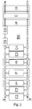
- FIG. 1 shows a basic configuration BK according to a first embodiment.
- the basic configuration BK comprises six energy generators E1 ... E6, three buffer storage tanks P, PP, PS and three energy transfers Ü, ÜP, ÜS, which are each arranged on a flow V and a return R.
- the energy generators E5, E6, which are connected in series, have no direct connection with the return.
- the number of energy generators can be expanded as required, which is indicated by the dots in the representation of the flow and return lines.
- a device In order to configure a specific infrastructure of a multivalent energy supply system, a device according to the invention comprises a detection device.
- the device can be, for example, a computer, tablet, smartphone or some other device with a graphical user interface.
- a basic configuration BK is stored in a memory of the device.
- the basic configuration BK can be loaded from the memory.
- a graphic representation of the basic configuration BK can be displayed in a menu. By clicking or touching, an installer or other user can select specific versions for each of the components from a list or a graphical representation of components in a menu guide.
- the system configuration AK generated can be a hydraulic diagram or block diagram of the energy supply system. Relationships between the components and information about their functions and effects are represented by the system configuration and can be recorded from this by a control device. Furthermore, measuring points, sensors and other components that are contained in the energy supply system can be added to the hydraulic diagram or block diagram (system configuration AK). For example, direct connections can be placed at unoccupied positions in the basic configuration BK.
- the hydraulic diagram or the block diagram AK of the energy supply system is thus created step by step. After all components have been selected, the finished configuration can be saved and transferred to a control device. The generated hydraulic scheme or the block diagram can then be used for controlling the energy supply system by the control device.
- Figure 2 shows a schematic representation of an embodiment of a multivalent energy supply system for providing heat and electrical energy.
- Figure 2 is a Hydraulic scheme of the energy supply system shown, which is based on a basic configuration according to BK Figure 1 was created by selecting the individual components.
- the energy supply system has two combined heat and power units (BHKW) B1, B2 and two gas boilers G1, G2, the two BHKWs B1, B2 each being arranged between a flow V and a return R parallel to one another.
- the carrier medium coming from the consumer side flows via the return R to the energy generators, which supply heat to the carrier medium.
- the carrier medium flows via the flow V to the consumer circuit (not shown).
- a first gas boiler G1 is also arranged parallel to the CHP units B1, B2 downstream on the supply line V. Further downstream on the flow V there is also a buffer store P parallel to the first gas boiler G1 and the CHPs B1, B2. Downstream of the buffer store P, a second gas boiler G2 is arranged in series in the flow V, so that the second gas boiler G2 can raise the flow temperature directly. Due to the arrangement of the second gas boiler G2 in the flow after the buffer storage, it cannot influence the temperature of the water stored in the buffer storage.
- the hydraulic scheme of the second exemplary embodiment is configured in that three energy generators B1, B2, G1 are selected in parallel to the buffer store P instead of the first energy generators E1, E2.
- the primary-side PP and secondary-side PS buffer storage are each configured as a direct connection.
- the gas boiler G2 is used as a serial energy generator at point E5 in Figure 1 is selected and E6 is configured as a direct connection.
- the energy transfers are also configured as a direct connection.
- FIG 3 shows a hydraulic diagram of an energy supply system according to a third embodiment. Similar to the second exemplary embodiment, the energy supply system has a buffer storage P between the flow V and return R and a gas boiler G1 in the flow V downstream of the buffer storage P. A first wood boiler H1 and a second wood boiler H2 are each arranged parallel to one another and parallel to the buffer store P upstream of the flow V1.
- the hydraulic scheme of the third exemplary embodiment is configured by selecting the two wood boilers H1, H2 in parallel to the buffer store P instead of the first energy generator E1, E2.
- the primary-side PP and Secondary PS buffer tanks are configured as a direct connection.
- the gas boiler G1 is the first serial energy generator at point E5 in Figure 1 is selected and E6 is configured as a direct connection.
- the energy transfers are also configured as a direct connection.
- FIG. 4 shows a hydraulic diagram of an energy supply system according to a fourth embodiment.
- a heat pump W1 and a gas boiler G1 are arranged parallel to one another and parallel to a buffer tank P between the flow V and return R.
- the hydraulic scheme of the fourth exemplary embodiment is configured by selecting the heat pump E1 and the gas boiler G1 in parallel to the buffer storage tank P instead of the first energy generator E1, E2.
- the primary-side PP and secondary-side PS buffer storage are each configured as a direct connection.
- the serial energy generators E5 and E6 are configured as a direct connection.
- the energy transfers are also configured as a direct connection.
- the energy supply system comprises two gas boilers G1, G2 and two oil boilers O1, O2, all of which are arranged parallel to one another between flow V and return R.
- a heat transfer is provided for transferring the heat to a consumer circuit.
- a hydraulic diagram of the energy supply system according to the fifth exemplary embodiment is shown in FIG Figure 5 shown.
- the hydraulic scheme of the fifth embodiment is configured by selecting the two gas boilers G1, G2 instead of the first energy generator E1, E2.
- the two oil boilers O1, O2 are selected in place of the second energy generators E3, E4.
- the buffer storage P and the primary-side PP and secondary-side PS buffer storage are each configured as a direct connection.
- the serial energy generators E5 and E6 are configured as a direct connection.
- the energy transfer Ü is configured as heat transfer WÜ.
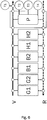
- FIG. 6 shows a hydraulic diagram of a multivalent energy supply system according to a sixth embodiment.
- the energy supply system comprises two gas boilers G1, G2, two BKHWs B1, B2 and two wood boilers H1, H2 as well as a buffer storage P.
- a temperature sensor T1 is arranged in the flow V, which measures the energy supply system flow temperature.
- Three temperature sensors T2, T3, T4 are arranged in the buffer memory P, each of which measures the temperature in the buffer memory P, respectively in an upper area, in a middle area and in a lower area of the buffer memory.
- the hydraulic scheme of the sixth exemplary embodiment is configured by selecting the two gas boilers G1, G2, two BKHWs B1, B2 and two wood boilers H1, H2 instead of the first energy generators E1, E2.
- the buffer storage P is configured as a buffer storage with four temperature sensors T1 to T4.
- the primary-side PP and secondary-side PS buffer storage are each configured as a direct connection.
- the serial energy generators E5 and E6 are also configured as direct connections.
- the energy supply system is controlled depending on the recorded configuration. All six energy generators can heat directly to the flow or the buffer. Since all energy producers are connected in parallel, they could work independently of one another.
- a specification for a control device can be that a large amount of energy should be stored in the buffer store P. From the hydraulic diagram, the control device recognizes that all energy generators can be used to store heat. The control device also recognizes that a buffer temperature sensor T4 at a lower area of the buffer memory P can be selected for the buffer temperature regulation. The target buffer temperature is set to 70 ° C, for example. The control device S then ensures that the buffer memory P is fully charged with a temperature of 70.degree.
- a buffer temperature sensor T3 is selected in a central area of the buffer memory P for the buffer temperature control.
- a buffer temperature sensor T2 is selected at an upper area of the buffer memory P for the buffer temperature control. It is not necessary to specify a target buffer temperature, as a target energy generator flow temperature can be calculated from a target system flow temperature. Only as much energy is generated as from the consumers, the buffer memory P is not loaded in this case.
- the system flow temperature can, for example, be measured by a temperature sensor T1 on flow V.
Landscapes
- Engineering & Computer Science (AREA)
- Physics & Mathematics (AREA)
- General Engineering & Computer Science (AREA)
- Chemical & Material Sciences (AREA)
- Combustion & Propulsion (AREA)
- Mechanical Engineering (AREA)
- Thermal Sciences (AREA)
- General Physics & Mathematics (AREA)
- Automation & Control Theory (AREA)
- Supply And Distribution Of Alternating Current (AREA)
- Management, Administration, Business Operations System, And Electronic Commerce (AREA)
- Charge And Discharge Circuits For Batteries Or The Like (AREA)
- Engine Equipment That Uses Special Cycles (AREA)
Priority Applications (1)
| Application Number | Priority Date | Filing Date | Title |
|---|---|---|---|
| PL17713249T PL3433684T3 (pl) | 2016-03-24 | 2017-03-23 | Urządzenie i sposób konfiguracji wielowartościowej instalacji zasilania w energię |
Applications Claiming Priority (2)
| Application Number | Priority Date | Filing Date | Title |
|---|---|---|---|
| DE102016205033.8A DE102016205033A1 (de) | 2016-03-24 | 2016-03-24 | Vorrichtung und Verfahren zum Konfigurieren einer multivalenten Energieversorgungsanlage |
| PCT/EP2017/056930 WO2017162796A1 (de) | 2016-03-24 | 2017-03-23 | Vorrichtung und verfahren zum konfigurieren einer multivalenten energieversorgungsanlage |
Publications (2)
| Publication Number | Publication Date |
|---|---|
| EP3433684A1 EP3433684A1 (de) | 2019-01-30 |
| EP3433684B1 true EP3433684B1 (de) | 2021-05-12 |
Family
ID=58410314
Family Applications (1)
| Application Number | Title | Priority Date | Filing Date |
|---|---|---|---|
| EP17713249.5A Active EP3433684B1 (de) | 2016-03-24 | 2017-03-23 | Vorrichtung und verfahren zum konfigurieren einer multivalenten energieversorgungsanlage |
Country Status (7)
| Country | Link |
|---|---|
| US (1) | US20190107295A1 (pl) |
| EP (1) | EP3433684B1 (pl) |
| CA (1) | CA3018609C (pl) |
| DE (1) | DE102016205033A1 (pl) |
| PL (1) | PL3433684T3 (pl) |
| RU (1) | RU2727209C2 (pl) |
| WO (1) | WO2017162796A1 (pl) |
Families Citing this family (2)
| Publication number | Priority date | Publication date | Assignee | Title |
|---|---|---|---|---|
| DE102020002602A1 (de) | 2020-04-30 | 2021-11-04 | Wieland Petter | Verfahren zum Erzeugen elektrischer Energie |
| LU505389B1 (en) * | 2023-10-27 | 2025-04-28 | Bdr Thermea Group B V | Method for commissioning a hybrid system |
Family Cites Families (12)
| Publication number | Priority date | Publication date | Assignee | Title |
|---|---|---|---|---|
| DE2711601A1 (de) * | 1977-03-17 | 1978-09-21 | Bosch Gmbh Robert | Einrichtung zum regeln einer umlaufwasser-heizungsanlage |
| DE10348563B4 (de) * | 2002-10-22 | 2014-01-09 | Fisher-Rosemount Systems, Inc. | Integration von Grafikdisplayelementen, Prozeßmodulen und Steuermodulen in Prozeßanlagen |
| US8065131B2 (en) * | 2005-07-29 | 2011-11-22 | General Electric Company | Configurable system and method for power and process plant modeling |
| DE202006001553U1 (de) * | 2006-02-01 | 2006-06-29 | Handwerkskammer Osnabrück-Emsland | Schulungsgerät |
| US7778806B2 (en) * | 2006-03-29 | 2010-08-17 | Hitachi, Ltd | Method and apparatus for simulating microcomputer-based systems |
| US20080179416A1 (en) | 2007-01-26 | 2008-07-31 | Johnson David E | Modulation control of a hydronic heating system |
| DE202007002733U1 (de) * | 2007-02-24 | 2007-06-06 | Gross, Hermann | Anlage zur Erzeugung, Speicherung und Verteilung von Wärmeenergie zwischen wärmetechnischen Betriebsmitteln mit abgestuften Temperaturniveaus in einem Gebäude und Steigerung zum Betrieb einer solchen Anlage |
| DE102007061415A1 (de) * | 2007-12-16 | 2009-07-23 | Viessmann Werke Gmbh & Co Kg | Heizungsanlage |
| DE102008001942B3 (de) * | 2008-05-23 | 2009-11-19 | Webasto Ag | Mobiles Heizsystem |
| DE102008057730A1 (de) | 2008-11-17 | 2010-05-20 | Brüning, Olaf | Verfahren zum Betreiben eines Systems zum Transport thermischer Energie über ein flüssiges Medium |
| DE102008063954B3 (de) * | 2008-12-25 | 2010-07-22 | Mayer, Michael, Dipl.-Ing. | Verfahren zum Regeln mindestens einer dezentralen Energieversorgungsanlage nach zumindest ökologischen Zielvorgaben, die insbesondere die Minimierung von CO2-Emissionen umfassen, sowie nach dem Verfahren geregelte dezentrale Energieversorgungsanlage |
| DE102012024583A1 (de) * | 2012-12-17 | 2014-06-18 | Meibes System-Technik Gmbh | Mehrkreisige Heizungs- oder Kühlanlage mit Pufferspeicher, Einrichtung zum Steuern und/oder Regeln für eine mehrkreisige Heizungs- oder Kühlanlage mit Pufferspeicher und Verfahren zum Betreiben einer mehrkreisigen Heizungs- oder Kühlanlage mit Pufferspeic |
-
2016
- 2016-03-24 DE DE102016205033.8A patent/DE102016205033A1/de not_active Ceased
-
2017
- 2017-03-23 US US16/087,660 patent/US20190107295A1/en not_active Abandoned
- 2017-03-23 CA CA3018609A patent/CA3018609C/en active Active
- 2017-03-23 PL PL17713249T patent/PL3433684T3/pl unknown
- 2017-03-23 RU RU2018137204A patent/RU2727209C2/ru active
- 2017-03-23 EP EP17713249.5A patent/EP3433684B1/de active Active
- 2017-03-23 WO PCT/EP2017/056930 patent/WO2017162796A1/de not_active Ceased
Also Published As
| Publication number | Publication date |
|---|---|
| WO2017162796A1 (de) | 2017-09-28 |
| RU2018137204A (ru) | 2020-04-28 |
| EP3433684A1 (de) | 2019-01-30 |
| CA3018609C (en) | 2023-08-29 |
| DE102016205033A1 (de) | 2017-09-28 |
| RU2727209C2 (ru) | 2020-07-21 |
| CA3018609A1 (en) | 2017-09-28 |
| RU2018137204A3 (pl) | 2020-05-18 |
| US20190107295A1 (en) | 2019-04-11 |
| PL3433684T3 (pl) | 2021-11-22 |
Similar Documents
| Publication | Publication Date | Title |
|---|---|---|
| EP2084801A1 (de) | Verfahren zum betreiben eines niederspannungsnetzes | |
| DE202011005048U1 (de) | Elektrische Energieverteilungsvorrichtung für ein Gebäude | |
| EP3683648B1 (de) | Verfahren zum steuern einer energieversogungsanlage | |
| EP3433827B1 (de) | Verfahren zum steuern einer multivalenten energieversorgungsanlage | |
| WO2007096377A1 (de) | Modellbasierte prädiktive regelung einer gebäude-energieanlage | |
| DE102012108496A1 (de) | Energiewandlervorrichtung und Verfahren zum Bereitstellen von Regelleistung | |
| EP3433684A1 (de) | Vorrichtung und verfahren zum konfigurieren einer multivalenten energieversorgungsanlage | |
| DE102021006564B4 (de) | Verfahren zum betreiben eines heizungssystems mit brennstoffzelle und heizungssystem mit brennstoffzelle | |
| DE102010050020B4 (de) | System und Verfahren zur vollständigen und uneingeschränkten Nutzung von ungesteuert erzeugter elektrischer Energie | |
| EP3433824B1 (de) | Verfahren zum steuern einer multivalenten energieversorgungsanlage | |
| DE102018105965A1 (de) | Heizgerät | |
| DE102021203798A1 (de) | Verfahren zum betreiben eines heizungssystems mit brennstoffzelle und heizungssystem mit brennstoffzelle | |
| EP2820735A1 (de) | Elektrisches gerät und verfahren zum ansteuern eines elektrischen energieerzeugers | |
| CH705028A2 (de) | Anlage zur Kraft-Wärmekopplung mit kombinierten Wärmespeichern. | |
| EP0998006B1 (de) | Anordnung und Verfahren zum Angleichen der Leistung eines elektrischen Versorgungsnetzes an aktuelle Spitzenlasten | |
| EP3433825B1 (de) | Verfahren zum steuern einer multivalenten energieversorgungsanlage | |
| DE102017223549A1 (de) | Energiesystem und Verfahren zum Betrieb eines Energiesystems | |
| DE102012018797B4 (de) | Wärmeenergieversorgungsanlage und Verfahren zu deren Betrieb | |
| DE102020123209A1 (de) | Energiesystem und Verfahren zum Steuern eines Energiesystems mit hydraulischer Systemtrennung | |
| EP3859929B1 (de) | Energiesystem sowie verfahren und vorrichtungen zu dessen steuerung | |
| WO2010109006A1 (de) | System zur computergestützten optimierung des gesamtwirkungsgrades einer produktionsanlage | |
| DE102024104078A1 (de) | Schaltungsvorrichtung | |
| DE202021100957U1 (de) | Wärmetauschersystem | |
| DE102012100864A1 (de) | Verfahren zur Verteilung einer Strommenge eines lokalen Stromerzeugers, Stromverteilungseinrichtung und ein Stromnetzwerk mit einer solchen Stromverteilungseinrichtung | |
| DE202013003174U1 (de) | Energiespeicher und Energieverteilung |
Legal Events
| Date | Code | Title | Description |
|---|---|---|---|
| STAA | Information on the status of an ep patent application or granted ep patent |
Free format text: STATUS: UNKNOWN |
|
| STAA | Information on the status of an ep patent application or granted ep patent |
Free format text: STATUS: THE INTERNATIONAL PUBLICATION HAS BEEN MADE |
|
| PUAI | Public reference made under article 153(3) epc to a published international application that has entered the european phase |
Free format text: ORIGINAL CODE: 0009012 |
|
| STAA | Information on the status of an ep patent application or granted ep patent |
Free format text: STATUS: REQUEST FOR EXAMINATION WAS MADE |
|
| 17P | Request for examination filed |
Effective date: 20181024 |
|
| AK | Designated contracting states |
Kind code of ref document: A1 Designated state(s): AL AT BE BG CH CY CZ DE DK EE ES FI FR GB GR HR HU IE IS IT LI LT LU LV MC MK MT NL NO PL PT RO RS SE SI SK SM TR |
|
| AX | Request for extension of the european patent |
Extension state: BA ME |
|
| RIN1 | Information on inventor provided before grant (corrected) |
Inventor name: BOCK, MARTIN Inventor name: MAURER, TOBIAS Inventor name: TIMMERMANN, JOERG Inventor name: OSTERLOH, REINHARD Inventor name: GRAD, ANDREJ Inventor name: ARNOLD, CHRISTIAN |
|
| DAV | Request for validation of the european patent (deleted) | ||
| DAX | Request for extension of the european patent (deleted) | ||
| GRAP | Despatch of communication of intention to grant a patent |
Free format text: ORIGINAL CODE: EPIDOSNIGR1 |
|
| STAA | Information on the status of an ep patent application or granted ep patent |
Free format text: STATUS: GRANT OF PATENT IS INTENDED |
|
| INTG | Intention to grant announced |
Effective date: 20201203 |
|
| RAP1 | Party data changed (applicant data changed or rights of an application transferred) |
Owner name: VIESSMANN CLIMATE SOLUTIONS SE |
|
| GRAS | Grant fee paid |
Free format text: ORIGINAL CODE: EPIDOSNIGR3 |
|
| GRAA | (expected) grant |
Free format text: ORIGINAL CODE: 0009210 |
|
| STAA | Information on the status of an ep patent application or granted ep patent |
Free format text: STATUS: THE PATENT HAS BEEN GRANTED |
|
| AK | Designated contracting states |
Kind code of ref document: B1 Designated state(s): AL AT BE BG CH CY CZ DE DK EE ES FI FR GB GR HR HU IE IS IT LI LT LU LV MC MK MT NL NO PL PT RO RS SE SI SK SM TR |
|
| REG | Reference to a national code |
Ref country code: GB Ref legal event code: FG4D Free format text: NOT ENGLISH |
|
| REG | Reference to a national code |
Ref country code: CH Ref legal event code: EP |
|
| REG | Reference to a national code |
Ref country code: DE Ref legal event code: R096 Ref document number: 502017010346 Country of ref document: DE |
|
| REG | Reference to a national code |
Ref country code: IE Ref legal event code: FG4D Free format text: LANGUAGE OF EP DOCUMENT: GERMAN |
|
| REG | Reference to a national code |
Ref country code: AT Ref legal event code: REF Ref document number: 1392592 Country of ref document: AT Kind code of ref document: T Effective date: 20210615 |
|
| REG | Reference to a national code |
Ref country code: NL Ref legal event code: FP |
|
| REG | Reference to a national code |
Ref country code: LT Ref legal event code: MG9D |
|
| PG25 | Lapsed in a contracting state [announced via postgrant information from national office to epo] |
Ref country code: HR Free format text: LAPSE BECAUSE OF FAILURE TO SUBMIT A TRANSLATION OF THE DESCRIPTION OR TO PAY THE FEE WITHIN THE PRESCRIBED TIME-LIMIT Effective date: 20210512 Ref country code: BG Free format text: LAPSE BECAUSE OF FAILURE TO SUBMIT A TRANSLATION OF THE DESCRIPTION OR TO PAY THE FEE WITHIN THE PRESCRIBED TIME-LIMIT Effective date: 20210812 Ref country code: FI Free format text: LAPSE BECAUSE OF FAILURE TO SUBMIT A TRANSLATION OF THE DESCRIPTION OR TO PAY THE FEE WITHIN THE PRESCRIBED TIME-LIMIT Effective date: 20210512 Ref country code: LT Free format text: LAPSE BECAUSE OF FAILURE TO SUBMIT A TRANSLATION OF THE DESCRIPTION OR TO PAY THE FEE WITHIN THE PRESCRIBED TIME-LIMIT Effective date: 20210512 |
|
| PG25 | Lapsed in a contracting state [announced via postgrant information from national office to epo] |
Ref country code: IS Free format text: LAPSE BECAUSE OF FAILURE TO SUBMIT A TRANSLATION OF THE DESCRIPTION OR TO PAY THE FEE WITHIN THE PRESCRIBED TIME-LIMIT Effective date: 20210912 Ref country code: LV Free format text: LAPSE BECAUSE OF FAILURE TO SUBMIT A TRANSLATION OF THE DESCRIPTION OR TO PAY THE FEE WITHIN THE PRESCRIBED TIME-LIMIT Effective date: 20210512 Ref country code: GR Free format text: LAPSE BECAUSE OF FAILURE TO SUBMIT A TRANSLATION OF THE DESCRIPTION OR TO PAY THE FEE WITHIN THE PRESCRIBED TIME-LIMIT Effective date: 20210813 Ref country code: NO Free format text: LAPSE BECAUSE OF FAILURE TO SUBMIT A TRANSLATION OF THE DESCRIPTION OR TO PAY THE FEE WITHIN THE PRESCRIBED TIME-LIMIT Effective date: 20210812 Ref country code: PT Free format text: LAPSE BECAUSE OF FAILURE TO SUBMIT A TRANSLATION OF THE DESCRIPTION OR TO PAY THE FEE WITHIN THE PRESCRIBED TIME-LIMIT Effective date: 20210913 Ref country code: RS Free format text: LAPSE BECAUSE OF FAILURE TO SUBMIT A TRANSLATION OF THE DESCRIPTION OR TO PAY THE FEE WITHIN THE PRESCRIBED TIME-LIMIT Effective date: 20210512 Ref country code: SE Free format text: LAPSE BECAUSE OF FAILURE TO SUBMIT A TRANSLATION OF THE DESCRIPTION OR TO PAY THE FEE WITHIN THE PRESCRIBED TIME-LIMIT Effective date: 20210512 |
|
| PG25 | Lapsed in a contracting state [announced via postgrant information from national office to epo] |
Ref country code: RO Free format text: LAPSE BECAUSE OF FAILURE TO SUBMIT A TRANSLATION OF THE DESCRIPTION OR TO PAY THE FEE WITHIN THE PRESCRIBED TIME-LIMIT Effective date: 20210512 Ref country code: ES Free format text: LAPSE BECAUSE OF FAILURE TO SUBMIT A TRANSLATION OF THE DESCRIPTION OR TO PAY THE FEE WITHIN THE PRESCRIBED TIME-LIMIT Effective date: 20210512 Ref country code: EE Free format text: LAPSE BECAUSE OF FAILURE TO SUBMIT A TRANSLATION OF THE DESCRIPTION OR TO PAY THE FEE WITHIN THE PRESCRIBED TIME-LIMIT Effective date: 20210512 Ref country code: CZ Free format text: LAPSE BECAUSE OF FAILURE TO SUBMIT A TRANSLATION OF THE DESCRIPTION OR TO PAY THE FEE WITHIN THE PRESCRIBED TIME-LIMIT Effective date: 20210512 Ref country code: DK Free format text: LAPSE BECAUSE OF FAILURE TO SUBMIT A TRANSLATION OF THE DESCRIPTION OR TO PAY THE FEE WITHIN THE PRESCRIBED TIME-LIMIT Effective date: 20210512 Ref country code: SK Free format text: LAPSE BECAUSE OF FAILURE TO SUBMIT A TRANSLATION OF THE DESCRIPTION OR TO PAY THE FEE WITHIN THE PRESCRIBED TIME-LIMIT Effective date: 20210512 Ref country code: SM Free format text: LAPSE BECAUSE OF FAILURE TO SUBMIT A TRANSLATION OF THE DESCRIPTION OR TO PAY THE FEE WITHIN THE PRESCRIBED TIME-LIMIT Effective date: 20210512 |
|
| REG | Reference to a national code |
Ref country code: DE Ref legal event code: R097 Ref document number: 502017010346 Country of ref document: DE |
|
| PLBE | No opposition filed within time limit |
Free format text: ORIGINAL CODE: 0009261 |
|
| STAA | Information on the status of an ep patent application or granted ep patent |
Free format text: STATUS: NO OPPOSITION FILED WITHIN TIME LIMIT |
|
| 26N | No opposition filed |
Effective date: 20220215 |
|
| PG25 | Lapsed in a contracting state [announced via postgrant information from national office to epo] |
Ref country code: IS Free format text: LAPSE BECAUSE OF FAILURE TO SUBMIT A TRANSLATION OF THE DESCRIPTION OR TO PAY THE FEE WITHIN THE PRESCRIBED TIME-LIMIT Effective date: 20210912 Ref country code: AL Free format text: LAPSE BECAUSE OF FAILURE TO SUBMIT A TRANSLATION OF THE DESCRIPTION OR TO PAY THE FEE WITHIN THE PRESCRIBED TIME-LIMIT Effective date: 20210512 |
|
| PG25 | Lapsed in a contracting state [announced via postgrant information from national office to epo] |
Ref country code: MC Free format text: LAPSE BECAUSE OF FAILURE TO SUBMIT A TRANSLATION OF THE DESCRIPTION OR TO PAY THE FEE WITHIN THE PRESCRIBED TIME-LIMIT Effective date: 20210512 |
|
| GBPC | Gb: european patent ceased through non-payment of renewal fee |
Effective date: 20220323 |
|
| PG25 | Lapsed in a contracting state [announced via postgrant information from national office to epo] |
Ref country code: LU Free format text: LAPSE BECAUSE OF NON-PAYMENT OF DUE FEES Effective date: 20220323 Ref country code: IE Free format text: LAPSE BECAUSE OF NON-PAYMENT OF DUE FEES Effective date: 20220323 Ref country code: GB Free format text: LAPSE BECAUSE OF NON-PAYMENT OF DUE FEES Effective date: 20220323 |
|
| PGFP | Annual fee paid to national office [announced via postgrant information from national office to epo] |
Ref country code: AT Payment date: 20230317 Year of fee payment: 7 |
|
| PGFP | Annual fee paid to national office [announced via postgrant information from national office to epo] |
Ref country code: TR Payment date: 20230320 Year of fee payment: 7 |
|
| P01 | Opt-out of the competence of the unified patent court (upc) registered |
Effective date: 20230515 |
|
| PGFP | Annual fee paid to national office [announced via postgrant information from national office to epo] |
Ref country code: CH Payment date: 20230402 Year of fee payment: 7 |
|
| PG25 | Lapsed in a contracting state [announced via postgrant information from national office to epo] |
Ref country code: HU Free format text: LAPSE BECAUSE OF FAILURE TO SUBMIT A TRANSLATION OF THE DESCRIPTION OR TO PAY THE FEE WITHIN THE PRESCRIBED TIME-LIMIT; INVALID AB INITIO Effective date: 20170323 |
|
| PGFP | Annual fee paid to national office [announced via postgrant information from national office to epo] |
Ref country code: NL Payment date: 20240320 Year of fee payment: 8 |
|
| PG25 | Lapsed in a contracting state [announced via postgrant information from national office to epo] |
Ref country code: MK Free format text: LAPSE BECAUSE OF FAILURE TO SUBMIT A TRANSLATION OF THE DESCRIPTION OR TO PAY THE FEE WITHIN THE PRESCRIBED TIME-LIMIT Effective date: 20210512 Ref country code: CY Free format text: LAPSE BECAUSE OF FAILURE TO SUBMIT A TRANSLATION OF THE DESCRIPTION OR TO PAY THE FEE WITHIN THE PRESCRIBED TIME-LIMIT Effective date: 20210512 |
|
| PGFP | Annual fee paid to national office [announced via postgrant information from national office to epo] |
Ref country code: PL Payment date: 20240311 Year of fee payment: 8 |
|
| PG25 | Lapsed in a contracting state [announced via postgrant information from national office to epo] |
Ref country code: MT Free format text: LAPSE BECAUSE OF FAILURE TO SUBMIT A TRANSLATION OF THE DESCRIPTION OR TO PAY THE FEE WITHIN THE PRESCRIBED TIME-LIMIT Effective date: 20210512 |
|
| REG | Reference to a national code |
Ref country code: CH Ref legal event code: PL |
|
| REG | Reference to a national code |
Ref country code: AT Ref legal event code: MM01 Ref document number: 1392592 Country of ref document: AT Kind code of ref document: T Effective date: 20240323 |
|
| PG25 | Lapsed in a contracting state [announced via postgrant information from national office to epo] |
Ref country code: AT Free format text: LAPSE BECAUSE OF NON-PAYMENT OF DUE FEES Effective date: 20240323 |
|
| PG25 | Lapsed in a contracting state [announced via postgrant information from national office to epo] |
Ref country code: AT Free format text: LAPSE BECAUSE OF NON-PAYMENT OF DUE FEES Effective date: 20240323 Ref country code: CH Free format text: LAPSE BECAUSE OF NON-PAYMENT OF DUE FEES Effective date: 20240331 |
|
| PGFP | Annual fee paid to national office [announced via postgrant information from national office to epo] |
Ref country code: BE Payment date: 20250320 Year of fee payment: 9 |
|
| REG | Reference to a national code |
Ref country code: DE Ref legal event code: R081 Ref document number: 502017010346 Country of ref document: DE Owner name: VIESSMANN HOLDING INTERNATIONAL GMBH, DE Free format text: FORMER OWNER: VIESSMANN CLIMATE SOLUTIONS SE, 35108 ALLENDORF, DE |
|
| REG | Reference to a national code |
Ref country code: NL Ref legal event code: MM Effective date: 20250401 |
|
| PG25 | Lapsed in a contracting state [announced via postgrant information from national office to epo] |
Ref country code: NL Free format text: LAPSE BECAUSE OF NON-PAYMENT OF DUE FEES Effective date: 20250401 |
|
| PGFP | Annual fee paid to national office [announced via postgrant information from national office to epo] |
Ref country code: DE Payment date: 20260219 Year of fee payment: 10 |
|
| PGFP | Annual fee paid to national office [announced via postgrant information from national office to epo] |
Ref country code: IT Payment date: 20260219 Year of fee payment: 10 |
|
| PGFP | Annual fee paid to national office [announced via postgrant information from national office to epo] |
Ref country code: FR Payment date: 20260220 Year of fee payment: 10 |
|
| PG25 | Lapsed in a contracting state [announced via postgrant information from national office to epo] |
Ref country code: PL Free format text: LAPSE BECAUSE OF NON-PAYMENT OF DUE FEES Effective date: 20250323 |
|
| PG25 | Lapsed in a contracting state [announced via postgrant information from national office to epo] |
Ref country code: TR Free format text: LAPSE BECAUSE OF NON-PAYMENT OF DUE FEES Effective date: 20240323 |