EP3433550B1 - Klimaanlagenkreislauf eines kraftfahrzeugs - Google Patents
Klimaanlagenkreislauf eines kraftfahrzeugs Download PDFInfo
- Publication number
- EP3433550B1 EP3433550B1 EP17711251.3A EP17711251A EP3433550B1 EP 3433550 B1 EP3433550 B1 EP 3433550B1 EP 17711251 A EP17711251 A EP 17711251A EP 3433550 B1 EP3433550 B1 EP 3433550B1
- Authority
- EP
- European Patent Office
- Prior art keywords
- refrigerant
- heat exchanger
- ejector
- compressor
- conditioning circuit
- Prior art date
- Legal status (The legal status is an assumption and is not a legal conclusion. Google has not performed a legal analysis and makes no representation as to the accuracy of the status listed.)
- Active
Links
Images


Classifications
-
- F—MECHANICAL ENGINEERING; LIGHTING; HEATING; WEAPONS; BLASTING
- F25—REFRIGERATION OR COOLING; COMBINED HEATING AND REFRIGERATION SYSTEMS; HEAT PUMP SYSTEMS; MANUFACTURE OR STORAGE OF ICE; LIQUEFACTION SOLIDIFICATION OF GASES
- F25B—REFRIGERATION MACHINES, PLANTS OR SYSTEMS; COMBINED HEATING AND REFRIGERATION SYSTEMS; HEAT PUMP SYSTEMS
- F25B41/00—Fluid-circulation arrangements
-
- F—MECHANICAL ENGINEERING; LIGHTING; HEATING; WEAPONS; BLASTING
- F25—REFRIGERATION OR COOLING; COMBINED HEATING AND REFRIGERATION SYSTEMS; HEAT PUMP SYSTEMS; MANUFACTURE OR STORAGE OF ICE; LIQUEFACTION SOLIDIFICATION OF GASES
- F25B—REFRIGERATION MACHINES, PLANTS OR SYSTEMS; COMBINED HEATING AND REFRIGERATION SYSTEMS; HEAT PUMP SYSTEMS
- F25B5/00—Compression machines, plants or systems, with several evaporator circuits, e.g. for varying refrigerating capacity
- F25B5/02—Compression machines, plants or systems, with several evaporator circuits, e.g. for varying refrigerating capacity arranged in parallel
-
- F—MECHANICAL ENGINEERING; LIGHTING; HEATING; WEAPONS; BLASTING
- F25—REFRIGERATION OR COOLING; COMBINED HEATING AND REFRIGERATION SYSTEMS; HEAT PUMP SYSTEMS; MANUFACTURE OR STORAGE OF ICE; LIQUEFACTION SOLIDIFICATION OF GASES
- F25B—REFRIGERATION MACHINES, PLANTS OR SYSTEMS; COMBINED HEATING AND REFRIGERATION SYSTEMS; HEAT PUMP SYSTEMS
- F25B5/00—Compression machines, plants or systems, with several evaporator circuits, e.g. for varying refrigerating capacity
- F25B5/04—Compression machines, plants or systems, with several evaporator circuits, e.g. for varying refrigerating capacity arranged in series
-
- B—PERFORMING OPERATIONS; TRANSPORTING
- B60—VEHICLES IN GENERAL
- B60H—ARRANGEMENTS OF HEATING, COOLING, VENTILATING OR OTHER AIR-TREATING DEVICES SPECIALLY ADAPTED FOR PASSENGER OR GOODS SPACES OF VEHICLES
- B60H1/00—Heating, cooling or ventilating devices
- B60H1/32—Cooling devices
- B60H2001/3286—Constructional features
- B60H2001/3298—Ejector-type refrigerant circuits
-
- F—MECHANICAL ENGINEERING; LIGHTING; HEATING; WEAPONS; BLASTING
- F25—REFRIGERATION OR COOLING; COMBINED HEATING AND REFRIGERATION SYSTEMS; HEAT PUMP SYSTEMS; MANUFACTURE OR STORAGE OF ICE; LIQUEFACTION SOLIDIFICATION OF GASES
- F25B—REFRIGERATION MACHINES, PLANTS OR SYSTEMS; COMBINED HEATING AND REFRIGERATION SYSTEMS; HEAT PUMP SYSTEMS
- F25B2341/00—Details of ejectors not being used as compression device; Details of flow restrictors or expansion valves
- F25B2341/001—Ejectors not being used as compression device
- F25B2341/0012—Ejectors with the cooled primary flow at high pressure
-
- F—MECHANICAL ENGINEERING; LIGHTING; HEATING; WEAPONS; BLASTING
- F25—REFRIGERATION OR COOLING; COMBINED HEATING AND REFRIGERATION SYSTEMS; HEAT PUMP SYSTEMS; MANUFACTURE OR STORAGE OF ICE; LIQUEFACTION SOLIDIFICATION OF GASES
- F25B—REFRIGERATION MACHINES, PLANTS OR SYSTEMS; COMBINED HEATING AND REFRIGERATION SYSTEMS; HEAT PUMP SYSTEMS
- F25B2400/00—General features or devices for refrigeration machines, plants or systems, combined heating and refrigeration systems or heat-pump systems, i.e. not limited to a particular subgroup of F25B
- F25B2400/04—Refrigeration circuit bypassing means
- F25B2400/0409—Refrigeration circuit bypassing means for the evaporator
-
- F—MECHANICAL ENGINEERING; LIGHTING; HEATING; WEAPONS; BLASTING
- F25—REFRIGERATION OR COOLING; COMBINED HEATING AND REFRIGERATION SYSTEMS; HEAT PUMP SYSTEMS; MANUFACTURE OR STORAGE OF ICE; LIQUEFACTION SOLIDIFICATION OF GASES
- F25B—REFRIGERATION MACHINES, PLANTS OR SYSTEMS; COMBINED HEATING AND REFRIGERATION SYSTEMS; HEAT PUMP SYSTEMS
- F25B2400/00—General features or devices for refrigeration machines, plants or systems, combined heating and refrigeration systems or heat-pump systems, i.e. not limited to a particular subgroup of F25B
- F25B2400/04—Refrigeration circuit bypassing means
- F25B2400/0411—Refrigeration circuit bypassing means for the expansion valve or capillary tube
-
- F—MECHANICAL ENGINEERING; LIGHTING; HEATING; WEAPONS; BLASTING
- F25—REFRIGERATION OR COOLING; COMBINED HEATING AND REFRIGERATION SYSTEMS; HEAT PUMP SYSTEMS; MANUFACTURE OR STORAGE OF ICE; LIQUEFACTION SOLIDIFICATION OF GASES
- F25B—REFRIGERATION MACHINES, PLANTS OR SYSTEMS; COMBINED HEATING AND REFRIGERATION SYSTEMS; HEAT PUMP SYSTEMS
- F25B2400/00—General features or devices for refrigeration machines, plants or systems, combined heating and refrigeration systems or heat-pump systems, i.e. not limited to a particular subgroup of F25B
- F25B2400/23—Separators
Definitions
- the invention relates to the field of motor vehicles and more particularly to a motor vehicle air conditioning circuit.
- a refrigerant fluid passes successively in a compressor, a condenser placed in contact with an air flow outside the motor vehicle to release heat, an expansion device and an evaporator placed in contact with an air flow inside the motor vehicle to cool it.
- the performance of an air conditioning circuit is generally retranscribed by a coefficient of performance (COP for "coefficient of perfomance" in English) which corresponds to the quotient between the heat returned, at the condenser, and the work provided, in particular by the compressor .
- COP coefficient of performance
- the liquid phase of the refrigerant fluid is redirected towards the evaporator and the gas phase of the refrigerant fluid is in turn redirected to the compressor.
- the document FR-A-2 936 596 discloses an air conditioning circuit according to the preamble of claim 1.
- One of the aims of the present invention is therefore to at least partially overcome the disadvantages of the prior art and to provide an improved air conditioning circuit.
- the air conditioning circuit comprises a refrigerant management and distribution device from the ejector to the bypass line and / or the phase separation device.
- the management and distribution device comprises a first stop valve disposed between the first junction point and the phase separation device.
- the management and distribution device comprises a second stop valve disposed on the bypass line.
- the management and distribution device comprises a variable opening valve disposed on the bypass line.
- the management and distribution device comprises a variable-rate three-way valve disposed at the first junction point.
- the third heat exchanger is intended to be traversed by the interior air flow to the passenger compartment of the motor vehicle.
- the third heat exchanger is placed upstream of the second heat exchanger in the direction of flow of the interior air flow to the passenger compartment of the motor vehicle.
- the air conditioning circuit comprises an internal heat exchanger allowing a heat exchange between the refrigerant at the outlet of the first heat exchanger and the refrigerant at the outlet of the phase separation device and / or of the third heat exchanger.
- the refrigerant fluid at the outlet of the first heat exchanger passes into the internal heat exchanger before reaching the ejector, the gaseous phase of the refrigerant at the outlet of the phase separation device and the coolant at the outlet of the third heat exchanger mixes before passing into the internal heat exchanger and then back to the compressor.
- the air conditioning circuit is configured to operate in a second mode of operation where the refrigerant passes successively in the compressor, the first heat exchanger, the ejector, the third heat exchanger of the bypass before returning to the compressor.
- the refrigerant at the outlet of the first heat exchanger passes into the internal heat exchanger before reaching the ejector and the refrigerant at the outlet of the third heat exchanger passes through the heat exchanger. internal heat exchanger before returning to the compressor.
- the refrigerant at the outlet of the first heat exchanger passes into the internal heat exchanger before reaching the ejector and the gaseous phase of the refrigerant at the outlet of the phase separation device passes through the internal heat exchanger before returning to the compressor.
- first element or second element as well as first parameter and second parameter or else first criterion and second criterion, etc.
- first criterion and second criterion etc.
- it is a simple indexing to differentiate and name elements or parameters or criteria close but not identical.
- This indexing does not imply a priority of one element, parameter or criterion with respect to another, and it is easy to interchange such denominations without departing from the scope of the present description.
- This indexing does not imply either an order in time for example to appreciate this or that criterion.
- placed upstream means that one element is placed before another relative to the direction of flow of a fluid.
- downstream means that one element is placed after another relative to the direction of fluid flow.
- the refrigerant may in particular be carbon dioxide known in the field of air conditioning circuit under the name R744.
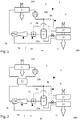
- the bypass line A also comprises a third heat exchanger 17.
- the air conditioning circuit may also include an internal heat exchanger 21 (IHX for "internai heat exchanger") allowing a heat exchange between the refrigerant at the outlet of the first heat exchanger 5 and the refrigerant at the outlet of the separation device 9 and / or the third heat exchanger 17.
- IHX internal heat exchanger
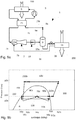
- bypass line A and the third heat exchanger 17 allows the air conditioning circuit 1 to operate according to a first operating mode illustrated in FIG. figure 3a where the flow direction of the coolant is represented by arrows.
- Curve B represents the saturation curve of the refrigerant fluid.
- the refrigerant at the inlet of the compressor 3 is in the gas phase at a pressure p1a and has an enthalpy h1a.
- the refrigerant is compressed, illustrated by the arrow 300, passing through the compressor 3 and goes to a pressure p2a for enthalpy h2a.
- the refrigerant passes through the first heat exchanger 5 and undergoes a loss of enthalpy, illustrated by the arrow 500, due to the heat dissipation in the outside air flow 100 and its passage in the liquid phase.
- the refrigerant then passes from an enthalpy h2a to an enthalpy h3a, while remaining at a constant pressure p2a.
- the refrigerant then passes into the first inlet 7a of the ejector 7.
- the refrigerant undergoes a loss of pressure, illustrated by the arrow 70a and crosses the saturation curve B, which makes it pass into a state of liquid mixture more gas.
- the refrigerant is then recompressed in the ejector 7 to reach the outlet 7c of said ejector 7, illustrated by point 70c.
- the coolant is at the pressure p1a and has an enthalpy h4a greater than the previous enthalpy h3a.
- Part of the refrigerant then passes into the phase separation device 9, while the other part of the coolant passes into the bypass line A.
- the liquid phase of the refrigerant fluid is separated from the gas phase.
- the enthalpy of the coolant in the liquid phase at the second outlet 9c of the phase separation device 9 decreases to reach the saturation curve B and reach a value h5a. This decrease is illustrated by the arrow 90c.
- the refrigerant then flows into the expansion device 11 where it undergoes a relaxation, illustrated by the arrow 110, passing from the pressure p1a to the pressure p3a.
- the refrigerant then passes through the second heat exchanger 13 where it undergoes evaporation, illustrated by the arrow 130.
- the refrigerant during its passage through the second heat exchanger 13 absorbs energy heat of the interior air flow 200 and passes from the enthalpy h5a to the enthalpy h6a.
- the refrigerant then flows back into the ejector 7 via its second inlet 7b, it again undergoes a loss of pressure and then a recompression in the ejector 7 to reach the point 70c, that is to say at a pressure p1a and an enthalpy h4a, as shown by arrow 70b.
- the gaseous phase of the refrigerant fluid is in turn redirected to the compressor 3. Due to the phase separation, the refrigerant fluid in the gaseous phase at the first outlet 9b of the separation device phase 9, tends to reach the saturation curve B gaining enthalpy, as shown by the arrow 90b. Before reaching the compressor 3 the refrigerant fluid from the first outlet 9a of the phase separation device 9 is mixed at the second junction point 15b with the refrigerant from the bypass line A.
- the refrigerant passes through the third heat exchanger 17 where it gains enthalpy as illustrated by the arrow 170.
- This mixture between the refrigerant in the gas phase from the separation device of phase 9 and the refrigerant resulting from the bypass line A makes it possible to reach the enthalpy h1a of the refrigerant which exceeds the saturation curve B.
- the refrigerant is therefore in a superheated gas state with enthalpy h1a and is at the pressure p1a before entering the compressor 3.
- the performance coefficient (COP for "coefficient of perfomance") is improved over a “conventional” air conditioning circuit in two ways.
- the COP is improved by the action of the ejector 7 which allows the refrigerant, at the inlet of the compressor 3, to have a pressure p1a greater than the pressure p3a where the heat exchange between the air flow 200 inside and the coolant takes place at the second heat exchanger 13. Less power at the compressor 3 is necessary to reach the pressure p2a.
- the COP is improved because of the presence of the third heat exchanger 17 which allows an overheating of the refrigerant before entering the compressor 3 and thus an enthalpy gain.
- the influence of the IHX 21 is visible on the pressure / enthalpy diagram of the figure 4b .
- the IHX 21 allows an increase in the enthalpy of the coolant, illustrated by the arrow 210a, before it enters the compressor 3.
- the refrigerant then passes from an enthalpy h1a to enthalpy h1'a and then to an enthalpy h2'a after passing through the compressor 3.
- This enthalpy h2'a is greater than the previous enthalpy h2a where there was no IHX 21.
- This increase in the enthalpy upstream of the compressor 3 is allowed by the decrease of the enthalpy of the refrigerant at the outlet of the first heat exchanger 5, illustrated by the arrow 210b.
- the IHX 21 improves the COP by decreasing the enthalpy of the refrigerant at the outlet of the first heat exchanger 5 and transferring it to the refrigerant before entering the compressor 3.
- the greater the enthalpy h3 'has fluid before arriving in the ejector 7 at the first inlet 7a is low, for example because of temperatures the lower the efficiency of the ejector 7 on the COP is good. Indeed, this limits the recompression of the refrigerant at the ejector 7 which allows the refrigerant to pass from the pressure p3a at the second heat exchanger 17 to the pressure p1a before entering the compressor 3. It should then increase the power of the compressor 3, and therefore reduce the COP, to compensate for this decrease in the pressure difference between p3a and p1a. For example, for low outside temperatures, the COP of an air conditioning circuit 1 with ejector 7 and IHX 21 may be less than a "conventional" air conditioning circuit including an IHX 21.
- the air conditioning circuit 1 comprises a bypass loop A comprising the third heat exchanger 17 limits this negative effect of the IHX 21 on the efficiency of the ejector 7. Indeed, the third heat exchanger This overheats the refrigerant which is thus at an enthalpy h1a before entering the IHX 21.
- the third heat exchanger 17 may for example be, like the second heat exchanger 13, to be traversed by an interior air flow 200 to the passenger compartment of the motor vehicle.
- said third heat exchanger 17 is preferably placed upstream of the second heat exchanger 13, in the direction of flow of the interior air flow 200 to the passenger compartment of the motor vehicle. Indeed, this allows the third heat exchanger 17 to be fed by a hot internal air flow 200 and to draw heat energy therefrom before said inner air flow 200 passes through the second heat exchanger 13. This also allows an increase in the exchange surface between the refrigerant and the internal air flow 200 and thus improves the heat exchange between said refrigerant and said indoor air flow 200.
- the latter may for example be a heat exchanger connected to another circuit exchange or thermal regulation of the vehicle with which it can exchange the heat. 'heat energy.
- the air conditioning circuit 1 may also include a management device and distribution 19 of the refrigerant from the ejector 7 to the bypass line A and / or the phase separation device 9. This management and distribution device 19 allows control of the circulation of the refrigerant.
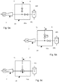
- the management and distribution device 19 may comprise a first stop valve 191 disposed between the first junction point and the phase separation device 9.
- the latter comprises a second stop valve 193 disposed on the bypass line A, in addition to the first stop valve 191.
- FIG. figure 5b it includes a variable opening valve 195 disposed on the bypass line A in addition to the first stop valve 191.
- the management and distribution device 19 may comprise a three-way valve 197 variable flow disposed at the first junction point 15a.
- the presence of the management and distribution device 19 allows the air conditioning circuit 1 to adopt different modes of operation. Indeed, it is possible to control towards where the coolant is directed. It is even possible, as required, to vary the amount of refrigerant sent to the second heat exchanger 13 or in the bypass line A, when the management and distribution device 19 comprises a variable opening valve. or a three-way valve 197 with variable flow.
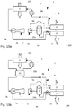
- the air conditioning circuit 1 can thus operate according to a second operating mode illustrated in FIG. figure 6a where the flow direction of the coolant is represented by arrows. In this second mode of operation, all the refrigerant at the outlet of the ejector 7 is redirected by the management and distribution device 19 to the third heat exchanger 17.
- the coolant passes successively in the compressor 3, the first heat exchanger 5, the ejector 7 and in the third heat exchanger 17 of the bypass line A before returning to the compressor 3.
- Curve B represents the saturation curve of the refrigerant fluid.
- the refrigerant at the inlet of the compressor 3 is in the gas phase at a pressure p1b and has an enthalpy h1b.
- the refrigerant is compressed, illustrated by the arrow 300, passing through the compressor 3 and goes to a pressure p2b and an enthalpy h2b.
- the refrigerant passes through the first heat exchanger 5 and undergoes a loss of enthalpy, illustrated by the arrow 500, due to the heat dissipation in the outside air flow 100 and its passage in the liquid phase.
- the refrigerant then passes from an enthalpy h2b to an enthalpy h3b, while remaining at a constant pressure p2b.
- the refrigerant then passes into the first inlet 7a of the ejector 7.
- the refrigerant undergoes a loss of pressure, illustrated by the arrow 700 and crosses the saturation curve B, which makes it pass into a state of liquid mixture more gas.
- the coolant is at the pressure p1b and has an enthalpy h3b.
- the refrigerant then passes into the management and distribution device 19 and is redirected in the bypass line A.
- the refrigerant passes through the third heat exchanger 17 where it gains enthalpy as illustrated by the arrow 170.
- the refrigerant then passes from enthalpy h3b to enthalpy h1b at the pressure p1b, before entering the compressor 3 again.
- the influence of the IHX 21 is visible on the pressure / enthalpy diagram of the figure 7b .
- the IHX 21 allows an increase in the enthalpy of the refrigerant fluid, illustrated by the arrow 210a, before it enters the compressor 3.
- the refrigerant then passes from an enthalpy h1b to an enthalpy h1'b and then to an enthalpy h2'b after passing through the compressor 3.
- This enthalpy h2'b is greater than the previous enthalpy h2b where there was no IHX 21.
- This increase in the enthalpy upstream of the compressor 3 is allowed by the decrease of the enthalpy of the refrigerant at the outlet of the first heat exchanger 5, illustrated by the arrow 210b.
- the IHX 21 improves the COP by decreasing the enthalpy of the refrigerant at the outlet of the first heat exchanger 5 and transferring it to the refrigerant before entering the compressor 3.
- This second mode of operation and its variant are equivalent to a "classic" operation of a “conventional” air conditioning circuit with and without IHX 21.
- the ejector 7 does not start and here has a simple regulator role.
- This second embodiment is preferably used for outside air temperatures at the inlet of the first heat exchanger less than 15 ° C and for refrigerants with a low thermal load.
- the air conditioning circuit 1 can also operate according to a third mode of operation illustrated in FIG. figure 8a where the flow direction of the coolant is represented by arrows. In this third mode of operation, all of the refrigerant at the outlet of the ejector 7 is redirected by the management and distribution device 19 to the phase separation device 9.
- Curve B represents the saturation curve of the refrigerant fluid.
- the refrigerant at the inlet of the compressor 3 is in the gas phase at a pressure p1c and has an enthalpy h1c.
- the refrigerant is compressed, illustrated by the arrow 300, passing through the compressor 3 and goes to a pressure p2c and an enthalpy h2c.
- the refrigerant passes through the first heat exchanger 5 and undergoes a loss of enthalpy, illustrated by the arrow 500, due to the heat dissipation in the outside air flow 100 and its passage in the liquid phase.
- the refrigerant then passes from an enthalpy h2c to an enthalpy h3c, while remaining at a constant pressure p2c.
- the refrigerant then passes into the first inlet 7a of the ejector 7.
- the refrigerant undergoes a loss of pressure, illustrated by the arrow 70a, and crosses the saturation curve B, which makes it pass into a state of liquid mixture more gas.
- the refrigerant is then recompressed in the ejector 7 to reach the outlet 7c of said ejector 7, illustrated by point 70c.
- the refrigerant is the pressure p1c and has an enthalpy h4c greater than the previous enthalpy h3a.
- the refrigerant then flows into the phase separation device 9.
- the liquid phase of the refrigerant is separated from the gas phase.
- the enthalpy of the refrigerant fluid in the liquid phase at the second output 9c of the phase separation device 9 decreases to reach the saturation curve B and reach a value h5c. This decrease is illustrated by the arrow 90c.
- the refrigerant then flows into the expansion device 11 where it undergoes an expansion, illustrated by the arrow 110, passing from the pressure p1c to the pressure p3c.
- the refrigerant then passes through the second heat exchanger 13 where it undergoes evaporation, illustrated by the arrow 130.
- the refrigerant during its passage through the second heat exchanger 13 absorbs heat energy from the interior air flow 200 and passes from enthalpy h5c to enthalpy h6c.
- the refrigerant then flows back into the ejector 7 via its second inlet 7b, it again undergoes a loss of pressure and then a recompression in the ejector 7 to reach the point 70c, that is to say at a pressure p1c and an enthalpy h4c, as shown by arrow 70b.
- the gas phase of the coolant is in turn redirected to the compressor 3. Because of the phase separation, the refrigerant in the gas phase at the first outlet 9b of the separation device of phase 9, tends to reach the saturation curve B by gaining enthalpy, as shown by the arrow 90b, and reaches the enthalpy h1c at the pressure p1c.
- the COP is improved compared to a "conventional" air conditioning circuit by the action of the ejector 7 which allows the refrigerant fluid at the inlet of said compressor 3 to have a pressure p1c greater than the pressure p3c where the heat exchange between the internal air flow 200 and the refrigerant, takes place at the second heat exchanger 13. Less power at the compressor 3 is necessary to reach the pressure p2c.
- This third mode of operation is preferably used for outside air temperatures at the inlet of the first heat exchanger 5 greater than 60 ° C and especially when the refrigerant is R744. Indeed, for such temperatures, the ejector 7 will subject the refrigerant a significant recompression and therefore the pressure within the phase separation device 9 will be too large and could damage the circuit.
- the influence of the IHX 21 is visible on the pressure / enthalpy diagram of the figure 9b .
- the IHX 21 allows an increase in the enthalpy of the refrigerant, illustrated by the arrow 210a, before it enters the compressor 3.
- the refrigerant then passes from an enthalpy h1c to an enthalpy h1'c and then to an enthalpy h2'c after passing through the compressor 3.
- This enthalpy h2'c is greater than the enthalpy h2c previous, where there was no IHX 21.
- This increase in the enthalpy upstream of the compressor 3 is enabled by the decrease of the enthalpy of the refrigerant at the outlet of the first heat exchanger 5, illustrated by the arrow 210b .
- the IHX 21 improves the COP by decreasing the enthalpy of the refrigerant at the outlet of the first heat exchanger 5 and transferring it to the refrigerant before entering the compressor 3.
- the air conditioning circuit 1 can also operate in a fourth mode of operation illustrated in FIG. figure 10a .
- the refrigerant fluid passes successively into the compressor 3, the first heat exchanger 5, the ejector 7, springing through the second inlet 7b of the said ejector 7, passes through the second heat exchanger 13, the device 11, the phase separation device 9, passes through the bypass line A, passes through the third heat exchanger 17 before returning to the compressor 3.
- the air conditioning circuit 1 allows use in different modes of operation and also allows optimization of the COP.
Landscapes
- Engineering & Computer Science (AREA)
- Physics & Mathematics (AREA)
- Mechanical Engineering (AREA)
- Thermal Sciences (AREA)
- General Engineering & Computer Science (AREA)
- Air-Conditioning For Vehicles (AREA)
Claims (15)
- Klimaanlagenkreislauf (1) für ein Kraftfahrzeug, in dem ein Kältemittel zirkuliert und der in Zirkulationsrichtung des Kältemittels aufweist:∘ einen Kompressor (3),∘ einen ersten Wärmetauscher (5), der dazu bestimmt ist, von einem Außenluftstrom (100) des Fahrzeugs durchströmt zu werden, und stromab des Kompressors (3) angeordnet ist,∘ einen Ejektor (7), der stromab des ersten Wärmetauschers (5) angeordnet ist und umfasst:• einen ersten Kältemitteleingang (7a), der mit dem ersten Wärmetauscher (5) verbunden ist,• einen zweiten Kältemitteleingang (7b) und• einen Kältemittelausgang (7c),∘ eine Phasentrennvorrichtung (9) für das Kältemittel, die aufweist:• einen Kältemitteleingang (9a), der mit dem Kältemittelausgang (7c) des Ejektors (7) verbunden ist,• einen ersten Ausgang (9b) für Kältemittel in gasförmiger Phase, der mit dem Kompressor (3) verbunden ist, und• einen zweiten Ausgang (9c) für Kältemittel in flüssiger Phase,∘ eine Entspannungsvorrichtung (11), die stromab des zweiten Kältemittelausgangs (9c) der Phasentrennvorrichtung (9) angeordnet ist,∘ einen zweiten Wärmetauscher (13), der dazu bestimmt ist, von einem für den Fahrgastraum des Kraftfahrzeugs bestimmten Innenluftstrom (200) durchströmt zu werden, wobei der zweite Tauscher (13) stromab der Entspannungsvorrichtung (11), zwischen der Entspannungsvorrichtung (11) und dem zweiten Kältemitteleingang (7b) des Ejektors (7), angeordnet ist,dadurch gekennzeichnet, dass der Klimaanlagenkreislauf (1) ferner eine Umgehungsleitung (A) zur Umgehung der Phasentrennvorrichtung (9) aufweist, die verbindet:wobei die Umgehungsleitung (A) einen dritten Wärmetauscher (17) aufweist.∘ eine erste Verbindungsstelle (15a), die stromab des Kältemittelausgangs (7c) des Ejektors (7), zwischen dem Ejektor (7) und der Phasentrennvorrichtung (9), angeordnet ist, und∘ eine zweite Verbindungsstelle (15b), die stromab des ersten Ausgangs (9b) der Phasentrennvorrichtung (9), zwischen der Phasentrennvorrichtung (9) und dem Kompressor (3), angeordnet ist,
- Klimaanlagenkreislauf (1) nach dem vorhergehenden Anspruch, dadurch gekennzeichnet, dass der Klimaanlagenkreislauf (1) eine Vorrichtung zur Steuerung und Verteilung (19) des vom Ejektor (7) kommenden Kältemittels zur Umgehungsleitung (A) und/oder zur Phasentrennvorrichtung (9) aufweist.
- Klimaanlagenkreislauf (1) nach Anspruch 2, dadurch gekennzeichnet, dass die Vorrichtung zur Steuerung und Verteilung (19) ein erstes Absperrventil (191) aufweist, das zwischen der ersten Verbindungsstelle und der Phasentrennvorrichtung (9) angeordnet ist.
- Klimaanlagenkreislauf (1) nach Anspruch 3, dadurch gekennzeichnet, dass die Vorrichtung zur Steuerung und Verteilung (19) ein zweites Absperrventil (193) aufweist, das an der Umgehungsleitung (A) angeordnet ist.
- Klimaanlagenkreislauf (1) nach Anspruch 3, dadurch gekennzeichnet, dass die Vorrichtung zur Steuerung und Verteilung (19) ein Ventil mit variabler Öffnung (195) aufweist, das an der Umgehungsleitung (A) angeordnet ist.
- Klimaanlagenkreislauf (1) nach Anspruch 2, dadurch gekennzeichnet, dass die Vorrichtung zur Steuerung und Verteilung (19) ein Dreiwegeventil (197) mit variablem Durchfluss aufweist, das auf Ebene der ersten Verbindungsstelle (15a) angeordnet ist.
- Klimaanlagenkreislauf (1) nach einem der vorhergehenden Ansprüche, dadurch gekennzeichnet, dass der dritte Wärmetauscher (17) dazu bestimmt ist, von dem für den Fahrgastraum des Kraftfahrzeugs bestimmten Innenluftstrom (200) durchströmt zu werden.
- Klimaanlagenkreislauf (1) nach dem vorhergehenden Anspruch, dadurch gekennzeichnet, dass der dritte Wärmetauscher (17) stromauf des zweiten Wärmetauschers (13) in Zirkulationsrichtung des für den Fahrgastraum des Kraftfahrzeugs bestimmten Innenluftstroms (200) platziert ist.
- Klimaanlagenkreislauf (1) nach einem der vorhergehenden Ansprüche, dadurch gekennzeichnet, dass er einen inneren Wärmetauscher (21) aufweist, der einen Wärmeaustausch zwischen dem aus dem ersten Wärmetauscher (5) austretenden Kältemittel und dem aus der Phasentrennvorrichtung (9) und/oder dem dritten Wärmetauscher (17) austretenden Kältemittel ermöglicht.
- Klimaanlagenkreislauf (1) nach einem der Ansprüche 1 bis 8, dadurch gekennzeichnet, dass er dazu ausgestaltet ist, in einer ersten Betriebsart betrieben zu werden, in der das Kältemittel nacheinander in den Kompressor (3), den ersten Wärmetauscher (5), den Ejektor (7) strömt,∘ wobei ein erster Kältemittelanteil durch die Phasentrennvorrichtung (9) strömt und:• die flüssige Phase des Kältemittels anschließend in die Entspannungsvorrichtung (11), den zweiten Wärmetauscher (13) strömt, wobei das Kältemittel in den Ejektor (7) zurückkommt,• die gasförmige Phase des Kältemittels zum Kompressor zurückkehrt (3) und∘ ein zweiter Kältemittelanteil durch den dritten Wärmetauscher (17) der Umgehungsleitung (A) strömt, bevor er zum Kompressor (3) zurückkehrt.
- Klimaanlagenkreislauf (1) nach den Ansprüchen 9 und 10, dadurch gekennzeichnet, dass das aus dem ersten Wärmetauscher (5) austretende Kältemittel in den inneren Wärmetauscher (21) strömt, bevor es zum Ejektor (7) gelangt, wobei die aus der Phasentrennvorrichtung (9) austretende gasförmige Phase des Kältemittels und das aus dem dritten Wärmetauscher (17) austretende Kältemittel sich mischen, bevor sie in den inneren Wärmetauscher (21) strömen, um anschließend zum Kompressor (3) zurückzukehren.
- Klimaanlagenkreislauf (1) nach einem der Ansprüche 2 bis 8, dadurch gekennzeichnet, dass er dazu ausgestaltet ist, in einer zweiten Betriebsart betrieben zu werden, in der das Kältemittel nacheinander in den Kompressor (3), den ersten Wärmetauscher (5), den Ejektor (7), den dritten Wärmetauscher (17) der Umgehungsleitung (A) strömt, bevor es zum Kompressor (3) zurückkehrt.
- Klimaanlagenkreislauf (1) nach den Ansprüchen 9 und 12, dadurch gekennzeichnet, dass das aus dem ersten Wärmetauscher (5) austretende Kältemittel in den inneren Wärmetauscher (21) strömt, bevor es zum Ejektor (7) gelangt, und das aus dem dritten Wärmetauscher (17) austretende Kältemittel in den inneren Wärmetauscher (21) strömt, bevor es zum Kompressor (3) zurückkehrt.
- Klimaanlagenkreislauf (1) nach einem der Ansprüche 2 bis 8, dadurch gekennzeichnet, dass er dazu ausgestaltet ist, in einer dritten Betriebsart betrieben zu werden, in der das Kältemittel nacheinander in den Kompressor (3), den ersten Wärmetauscher (5), den Ejektor (7), die Phasentrennvorrichtung (9) strömt, und:∘ die flüssige Phase des Kältemittels anschließend in die Entspannungsvorrichtung (11), den zweiten Wärmetauscher (13) strömt, wobei das Kältemittel in den Ejektor (7) zurückkommt,∘ die gasförmige Phase des Kältemittels zum Kompressor zurückkehrt (3).
- Klimaanlagenkreislauf (1) nach den Ansprüchen 9 und 14, dadurch gekennzeichnet, dass das aus dem ersten Wärmetauscher (5) austretende Kältemittel in den inneren Wärmetauscher (21) strömt, bevor es zum Ejektor (7) gelangt, und die aus der Phasentrennvorrichtung (9) austretende gasförmige Phase des Kältemittels in den inneren Wärmetauscher (21) strömt, bevor sie zum Kompressor (3) zurückkehrt.
Applications Claiming Priority (2)
| Application Number | Priority Date | Filing Date | Title |
|---|---|---|---|
| FR1652619A FR3049340B1 (fr) | 2016-03-25 | 2016-03-25 | Circuit de climatisation de vehicule automobile |
| PCT/FR2017/050339 WO2017162940A1 (fr) | 2016-03-25 | 2017-02-14 | Circuit de climatisation de véhicule automobile |
Publications (2)
| Publication Number | Publication Date |
|---|---|
| EP3433550A1 EP3433550A1 (de) | 2019-01-30 |
| EP3433550B1 true EP3433550B1 (de) | 2019-10-09 |
Family
ID=56119566
Family Applications (1)
| Application Number | Title | Priority Date | Filing Date |
|---|---|---|---|
| EP17711251.3A Active EP3433550B1 (de) | 2016-03-25 | 2017-02-14 | Klimaanlagenkreislauf eines kraftfahrzeugs |
Country Status (4)
| Country | Link |
|---|---|
| EP (1) | EP3433550B1 (de) |
| CN (1) | CN109073291B (de) |
| FR (1) | FR3049340B1 (de) |
| WO (1) | WO2017162940A1 (de) |
Families Citing this family (2)
| Publication number | Priority date | Publication date | Assignee | Title |
|---|---|---|---|---|
| CN114754513A (zh) * | 2022-04-26 | 2022-07-15 | 九江湖心科技产业发展有限公司 | 一种可用于氢气液化的喷射器式分级制冷循环系统及其方法 |
| CN119953140B (zh) * | 2023-11-07 | 2025-11-25 | 中国科学院理化技术研究所 | 余热利用的热管理系统 |
Family Cites Families (6)
| Publication number | Priority date | Publication date | Assignee | Title |
|---|---|---|---|---|
| JP4358832B2 (ja) * | 2005-03-14 | 2009-11-04 | 三菱電機株式会社 | 冷凍空調装置 |
| JP5050563B2 (ja) * | 2007-02-27 | 2012-10-17 | 株式会社デンソー | エジェクタ及びエジェクタ式冷凍サイクル用ユニット |
| FR2936596B1 (fr) * | 2008-10-01 | 2013-12-06 | Valeo Systemes Thermiques | Ejecteur pour une boucle de climatisation |
| CN202145068U (zh) * | 2011-07-01 | 2012-02-15 | 浙江盾安机械有限公司 | 一种电动车用热泵式冷暖空调系统 |
| CN103192675B (zh) * | 2012-01-05 | 2016-05-25 | 杭州三花研究院有限公司 | 一种汽车空调系统 |
| CN103256746B (zh) * | 2012-02-16 | 2016-12-14 | 杭州三花研究院有限公司 | 一种汽车空调系统 |
-
2016
- 2016-03-25 FR FR1652619A patent/FR3049340B1/fr not_active Expired - Fee Related
-
2017
- 2017-02-14 CN CN201780018342.8A patent/CN109073291B/zh active Active
- 2017-02-14 WO PCT/FR2017/050339 patent/WO2017162940A1/fr not_active Ceased
- 2017-02-14 EP EP17711251.3A patent/EP3433550B1/de active Active
Non-Patent Citations (1)
| Title |
|---|
| None * |
Also Published As
| Publication number | Publication date |
|---|---|
| EP3433550A1 (de) | 2019-01-30 |
| WO2017162940A1 (fr) | 2017-09-28 |
| FR3049340A1 (fr) | 2017-09-29 |
| CN109073291A (zh) | 2018-12-21 |
| CN109073291B (zh) | 2020-12-01 |
| FR3049340B1 (fr) | 2018-03-16 |
Similar Documents
| Publication | Publication Date | Title |
|---|---|---|
| EP2933586B1 (de) | Eine Vorrichtung zur thermischen Konditionierung eines Raumes | |
| EP3606774B1 (de) | Indirekter reversibler klimatisierungskreislauf für ein kraftfahrzeug und zugehöriges betriebsverfahren | |
| FR3052236A1 (fr) | Circuit de climatisation de vehicule automobile | |
| EP3513134B1 (de) | Wärmeverwaltungsschaltung für kraftfahrzeug | |
| WO2018042091A1 (fr) | Circuit de climatisation inversible indirect de véhicule automobile et procédé de fonctionnement correspondant | |
| EP3914866B1 (de) | Klimaanlage eines kraftfahrzeugs und zugehöriges verwaltungsverfahren | |
| FR3028016A1 (fr) | Dispositif de gestion thermique de vehicule automobile | |
| EP3433550B1 (de) | Klimaanlagenkreislauf eines kraftfahrzeugs | |
| WO2020165512A1 (fr) | Dispositif de gestion thermique de véhicule automobile électrique ou hybride | |
| EP3263374A1 (de) | Reversibler klimatisierungskreislauf für ein kraftfahrzeug, und entsprechende funktionsweisen | |
| WO2021116564A1 (fr) | Dispositif de gestion thermique inversible | |
| WO2018211200A1 (fr) | Circuit de climatisation inversible indirect de vehicule automobile et procede de de gestion en mode pompe a chaleur | |
| FR3033290A1 (fr) | Circuit de climatisation de vehicule automobile | |
| FR3076490A1 (fr) | Circuit de climatisation inversible indirect de vehicule automobile | |
| FR3058783A1 (fr) | Circuit de climatisation inversible indirect de vehicule automobile et procede de fonctionnement correspondant | |
| WO2018042090A1 (fr) | Circuit de climatisation inversible indirect de véhicule automobile et procédé de fonctionnement correspondant | |
| EP1963657A1 (de) | Vorrichtung zur kühlung von einlassluft und rückgeführter abgase | |
| FR3030700A1 (fr) | Circuit de climatisation de vehicule automobile | |
| WO2020165513A1 (fr) | Dispositif de gestion thermique de véhicule automobile électrique ou hybride | |
| EP3521073A1 (de) | Thermischer steuerschaltkreis eines hybridfahrzeugs | |
| WO2020234057A1 (fr) | Dispositif de gestion thermique avec vanne de régulation de pression d'évaporation | |
| EP2641037A1 (de) | Klimatisierungskreis mit einem magnetventil und betrieb als wärmepumpe | |
| WO2018211199A1 (fr) | Circuit de climatisation inversible indirect de vehicule automobile et procede de gestion en mode de pompe a chaleur | |
| FR3092523A1 (fr) | Dispositif de gestion thermique d’un véhicule automobile avec vanne à pression constante | |
| WO2017207038A1 (fr) | Système de gestion thermique d'air d'admission d'un moteur thermique suralimenté |
Legal Events
| Date | Code | Title | Description |
|---|---|---|---|
| STAA | Information on the status of an ep patent application or granted ep patent |
Free format text: STATUS: UNKNOWN |
|
| STAA | Information on the status of an ep patent application or granted ep patent |
Free format text: STATUS: THE INTERNATIONAL PUBLICATION HAS BEEN MADE |
|
| PUAI | Public reference made under article 153(3) epc to a published international application that has entered the european phase |
Free format text: ORIGINAL CODE: 0009012 |
|
| STAA | Information on the status of an ep patent application or granted ep patent |
Free format text: STATUS: REQUEST FOR EXAMINATION WAS MADE |
|
| 17P | Request for examination filed |
Effective date: 20180918 |
|
| AK | Designated contracting states |
Kind code of ref document: A1 Designated state(s): AL AT BE BG CH CY CZ DE DK EE ES FI FR GB GR HR HU IE IS IT LI LT LU LV MC MK MT NL NO PL PT RO RS SE SI SK SM TR |
|
| AX | Request for extension of the european patent |
Extension state: BA ME |
|
| DAV | Request for validation of the european patent (deleted) | ||
| DAX | Request for extension of the european patent (deleted) | ||
| GRAP | Despatch of communication of intention to grant a patent |
Free format text: ORIGINAL CODE: EPIDOSNIGR1 |
|
| STAA | Information on the status of an ep patent application or granted ep patent |
Free format text: STATUS: GRANT OF PATENT IS INTENDED |
|
| INTG | Intention to grant announced |
Effective date: 20190715 |
|
| GRAS | Grant fee paid |
Free format text: ORIGINAL CODE: EPIDOSNIGR3 |
|
| GRAA | (expected) grant |
Free format text: ORIGINAL CODE: 0009210 |
|
| STAA | Information on the status of an ep patent application or granted ep patent |
Free format text: STATUS: THE PATENT HAS BEEN GRANTED |
|
| AK | Designated contracting states |
Kind code of ref document: B1 Designated state(s): AL AT BE BG CH CY CZ DE DK EE ES FI FR GB GR HR HU IE IS IT LI LT LU LV MC MK MT NL NO PL PT RO RS SE SI SK SM TR |
|
| REG | Reference to a national code |
Ref country code: GB Ref legal event code: FG4D Free format text: NOT ENGLISH |
|
| REG | Reference to a national code |
Ref country code: CH Ref legal event code: EP |
|
| REG | Reference to a national code |
Ref country code: IE Ref legal event code: FG4D Free format text: LANGUAGE OF EP DOCUMENT: FRENCH |
|
| REG | Reference to a national code |
Ref country code: DE Ref legal event code: R096 Ref document number: 602017007696 Country of ref document: DE |
|
| REG | Reference to a national code |
Ref country code: AT Ref legal event code: REF Ref document number: 1189307 Country of ref document: AT Kind code of ref document: T Effective date: 20191115 |
|
| REG | Reference to a national code |
Ref country code: NL Ref legal event code: MP Effective date: 20191009 |
|
| REG | Reference to a national code |
Ref country code: LT Ref legal event code: MG4D |
|
| REG | Reference to a national code |
Ref country code: AT Ref legal event code: MK05 Ref document number: 1189307 Country of ref document: AT Kind code of ref document: T Effective date: 20191009 |
|
| PG25 | Lapsed in a contracting state [announced via postgrant information from national office to epo] |
Ref country code: ES Free format text: LAPSE BECAUSE OF FAILURE TO SUBMIT A TRANSLATION OF THE DESCRIPTION OR TO PAY THE FEE WITHIN THE PRESCRIBED TIME-LIMIT Effective date: 20191009 Ref country code: PT Free format text: LAPSE BECAUSE OF FAILURE TO SUBMIT A TRANSLATION OF THE DESCRIPTION OR TO PAY THE FEE WITHIN THE PRESCRIBED TIME-LIMIT Effective date: 20200210 Ref country code: AT Free format text: LAPSE BECAUSE OF FAILURE TO SUBMIT A TRANSLATION OF THE DESCRIPTION OR TO PAY THE FEE WITHIN THE PRESCRIBED TIME-LIMIT Effective date: 20191009 Ref country code: LT Free format text: LAPSE BECAUSE OF FAILURE TO SUBMIT A TRANSLATION OF THE DESCRIPTION OR TO PAY THE FEE WITHIN THE PRESCRIBED TIME-LIMIT Effective date: 20191009 Ref country code: NL Free format text: LAPSE BECAUSE OF FAILURE TO SUBMIT A TRANSLATION OF THE DESCRIPTION OR TO PAY THE FEE WITHIN THE PRESCRIBED TIME-LIMIT Effective date: 20191009 Ref country code: FI Free format text: LAPSE BECAUSE OF FAILURE TO SUBMIT A TRANSLATION OF THE DESCRIPTION OR TO PAY THE FEE WITHIN THE PRESCRIBED TIME-LIMIT Effective date: 20191009 Ref country code: BG Free format text: LAPSE BECAUSE OF FAILURE TO SUBMIT A TRANSLATION OF THE DESCRIPTION OR TO PAY THE FEE WITHIN THE PRESCRIBED TIME-LIMIT Effective date: 20200109 Ref country code: NO Free format text: LAPSE BECAUSE OF FAILURE TO SUBMIT A TRANSLATION OF THE DESCRIPTION OR TO PAY THE FEE WITHIN THE PRESCRIBED TIME-LIMIT Effective date: 20200109 Ref country code: PL Free format text: LAPSE BECAUSE OF FAILURE TO SUBMIT A TRANSLATION OF THE DESCRIPTION OR TO PAY THE FEE WITHIN THE PRESCRIBED TIME-LIMIT Effective date: 20191009 Ref country code: GR Free format text: LAPSE BECAUSE OF FAILURE TO SUBMIT A TRANSLATION OF THE DESCRIPTION OR TO PAY THE FEE WITHIN THE PRESCRIBED TIME-LIMIT Effective date: 20200110 Ref country code: LV Free format text: LAPSE BECAUSE OF FAILURE TO SUBMIT A TRANSLATION OF THE DESCRIPTION OR TO PAY THE FEE WITHIN THE PRESCRIBED TIME-LIMIT Effective date: 20191009 Ref country code: SE Free format text: LAPSE BECAUSE OF FAILURE TO SUBMIT A TRANSLATION OF THE DESCRIPTION OR TO PAY THE FEE WITHIN THE PRESCRIBED TIME-LIMIT Effective date: 20191009 |
|
| PG25 | Lapsed in a contracting state [announced via postgrant information from national office to epo] |
Ref country code: HR Free format text: LAPSE BECAUSE OF FAILURE TO SUBMIT A TRANSLATION OF THE DESCRIPTION OR TO PAY THE FEE WITHIN THE PRESCRIBED TIME-LIMIT Effective date: 20191009 Ref country code: RS Free format text: LAPSE BECAUSE OF FAILURE TO SUBMIT A TRANSLATION OF THE DESCRIPTION OR TO PAY THE FEE WITHIN THE PRESCRIBED TIME-LIMIT Effective date: 20191009 Ref country code: IS Free format text: LAPSE BECAUSE OF FAILURE TO SUBMIT A TRANSLATION OF THE DESCRIPTION OR TO PAY THE FEE WITHIN THE PRESCRIBED TIME-LIMIT Effective date: 20200224 |
|
| PG25 | Lapsed in a contracting state [announced via postgrant information from national office to epo] |
Ref country code: AL Free format text: LAPSE BECAUSE OF FAILURE TO SUBMIT A TRANSLATION OF THE DESCRIPTION OR TO PAY THE FEE WITHIN THE PRESCRIBED TIME-LIMIT Effective date: 20191009 |
|
| REG | Reference to a national code |
Ref country code: DE Ref legal event code: R097 Ref document number: 602017007696 Country of ref document: DE |
|
| PG2D | Information on lapse in contracting state deleted |
Ref country code: IS |
|
| PG25 | Lapsed in a contracting state [announced via postgrant information from national office to epo] |
Ref country code: RO Free format text: LAPSE BECAUSE OF FAILURE TO SUBMIT A TRANSLATION OF THE DESCRIPTION OR TO PAY THE FEE WITHIN THE PRESCRIBED TIME-LIMIT Effective date: 20191009 Ref country code: DK Free format text: LAPSE BECAUSE OF FAILURE TO SUBMIT A TRANSLATION OF THE DESCRIPTION OR TO PAY THE FEE WITHIN THE PRESCRIBED TIME-LIMIT Effective date: 20191009 Ref country code: EE Free format text: LAPSE BECAUSE OF FAILURE TO SUBMIT A TRANSLATION OF THE DESCRIPTION OR TO PAY THE FEE WITHIN THE PRESCRIBED TIME-LIMIT Effective date: 20191009 Ref country code: CZ Free format text: LAPSE BECAUSE OF FAILURE TO SUBMIT A TRANSLATION OF THE DESCRIPTION OR TO PAY THE FEE WITHIN THE PRESCRIBED TIME-LIMIT Effective date: 20191009 Ref country code: IS Free format text: LAPSE BECAUSE OF FAILURE TO SUBMIT A TRANSLATION OF THE DESCRIPTION OR TO PAY THE FEE WITHIN THE PRESCRIBED TIME-LIMIT Effective date: 20200209 |
|
| PLBE | No opposition filed within time limit |
Free format text: ORIGINAL CODE: 0009261 |
|
| STAA | Information on the status of an ep patent application or granted ep patent |
Free format text: STATUS: NO OPPOSITION FILED WITHIN TIME LIMIT |
|
| PG25 | Lapsed in a contracting state [announced via postgrant information from national office to epo] |
Ref country code: SM Free format text: LAPSE BECAUSE OF FAILURE TO SUBMIT A TRANSLATION OF THE DESCRIPTION OR TO PAY THE FEE WITHIN THE PRESCRIBED TIME-LIMIT Effective date: 20191009 Ref country code: IT Free format text: LAPSE BECAUSE OF FAILURE TO SUBMIT A TRANSLATION OF THE DESCRIPTION OR TO PAY THE FEE WITHIN THE PRESCRIBED TIME-LIMIT Effective date: 20191009 Ref country code: SK Free format text: LAPSE BECAUSE OF FAILURE TO SUBMIT A TRANSLATION OF THE DESCRIPTION OR TO PAY THE FEE WITHIN THE PRESCRIBED TIME-LIMIT Effective date: 20191009 |
|
| 26N | No opposition filed |
Effective date: 20200710 |
|
| REG | Reference to a national code |
Ref country code: CH Ref legal event code: PL |
|
| REG | Reference to a national code |
Ref country code: BE Ref legal event code: MM Effective date: 20200229 |
|
| PG25 | Lapsed in a contracting state [announced via postgrant information from national office to epo] |
Ref country code: MC Free format text: LAPSE BECAUSE OF FAILURE TO SUBMIT A TRANSLATION OF THE DESCRIPTION OR TO PAY THE FEE WITHIN THE PRESCRIBED TIME-LIMIT Effective date: 20191009 Ref country code: LU Free format text: LAPSE BECAUSE OF NON-PAYMENT OF DUE FEES Effective date: 20200214 |
|
| PG25 | Lapsed in a contracting state [announced via postgrant information from national office to epo] |
Ref country code: SI Free format text: LAPSE BECAUSE OF FAILURE TO SUBMIT A TRANSLATION OF THE DESCRIPTION OR TO PAY THE FEE WITHIN THE PRESCRIBED TIME-LIMIT Effective date: 20191009 Ref country code: LI Free format text: LAPSE BECAUSE OF NON-PAYMENT OF DUE FEES Effective date: 20200229 Ref country code: CH Free format text: LAPSE BECAUSE OF NON-PAYMENT OF DUE FEES Effective date: 20200229 |
|
| PG25 | Lapsed in a contracting state [announced via postgrant information from national office to epo] |
Ref country code: IE Free format text: LAPSE BECAUSE OF NON-PAYMENT OF DUE FEES Effective date: 20200214 |
|
| PG25 | Lapsed in a contracting state [announced via postgrant information from national office to epo] |
Ref country code: BE Free format text: LAPSE BECAUSE OF NON-PAYMENT OF DUE FEES Effective date: 20200229 |
|
| GBPC | Gb: european patent ceased through non-payment of renewal fee |
Effective date: 20210214 |
|
| PG25 | Lapsed in a contracting state [announced via postgrant information from national office to epo] |
Ref country code: GB Free format text: LAPSE BECAUSE OF NON-PAYMENT OF DUE FEES Effective date: 20210214 |
|
| PG25 | Lapsed in a contracting state [announced via postgrant information from national office to epo] |
Ref country code: TR Free format text: LAPSE BECAUSE OF FAILURE TO SUBMIT A TRANSLATION OF THE DESCRIPTION OR TO PAY THE FEE WITHIN THE PRESCRIBED TIME-LIMIT Effective date: 20191009 Ref country code: MT Free format text: LAPSE BECAUSE OF FAILURE TO SUBMIT A TRANSLATION OF THE DESCRIPTION OR TO PAY THE FEE WITHIN THE PRESCRIBED TIME-LIMIT Effective date: 20191009 Ref country code: CY Free format text: LAPSE BECAUSE OF FAILURE TO SUBMIT A TRANSLATION OF THE DESCRIPTION OR TO PAY THE FEE WITHIN THE PRESCRIBED TIME-LIMIT Effective date: 20191009 |
|
| PG25 | Lapsed in a contracting state [announced via postgrant information from national office to epo] |
Ref country code: MK Free format text: LAPSE BECAUSE OF FAILURE TO SUBMIT A TRANSLATION OF THE DESCRIPTION OR TO PAY THE FEE WITHIN THE PRESCRIBED TIME-LIMIT Effective date: 20191009 |
|
| P01 | Opt-out of the competence of the unified patent court (upc) registered |
Effective date: 20230528 |
|
| PGFP | Annual fee paid to national office [announced via postgrant information from national office to epo] |
Ref country code: DE Payment date: 20250212 Year of fee payment: 9 |
|
| PGFP | Annual fee paid to national office [announced via postgrant information from national office to epo] |
Ref country code: FR Payment date: 20250225 Year of fee payment: 9 |