EP3513134B1 - Wärmeverwaltungsschaltung für kraftfahrzeug - Google Patents
Wärmeverwaltungsschaltung für kraftfahrzeug Download PDFInfo
- Publication number
- EP3513134B1 EP3513134B1 EP17780818.5A EP17780818A EP3513134B1 EP 3513134 B1 EP3513134 B1 EP 3513134B1 EP 17780818 A EP17780818 A EP 17780818A EP 3513134 B1 EP3513134 B1 EP 3513134B1
- Authority
- EP
- European Patent Office
- Prior art keywords
- heat exchanger
- refrigerant
- expansion device
- refrigerant fluid
- thermal management
- Prior art date
- Legal status (The legal status is an assumption and is not a legal conclusion. Google has not performed a legal analysis and makes no representation as to the accuracy of the status listed.)
- Active
Links
Images


Classifications
-
- F—MECHANICAL ENGINEERING; LIGHTING; HEATING; WEAPONS; BLASTING
- F25—REFRIGERATION OR COOLING; COMBINED HEATING AND REFRIGERATION SYSTEMS; HEAT PUMP SYSTEMS; MANUFACTURE OR STORAGE OF ICE; LIQUEFACTION SOLIDIFICATION OF GASES
- F25B—REFRIGERATION MACHINES, PLANTS OR SYSTEMS; COMBINED HEATING AND REFRIGERATION SYSTEMS; HEAT PUMP SYSTEMS
- F25B1/00—Compression machines, plants or systems with non-reversible cycle
- F25B1/10—Compression machines, plants or systems with non-reversible cycle with multi-stage compression
-
- B—PERFORMING OPERATIONS; TRANSPORTING
- B60—VEHICLES IN GENERAL
- B60H—ARRANGEMENTS OF HEATING, COOLING, VENTILATING OR OTHER AIR-TREATING DEVICES SPECIALLY ADAPTED FOR PASSENGER OR GOODS SPACES OF VEHICLES
- B60H1/00—Heating, cooling or ventilating devices
- B60H1/00642—Control systems or circuits; Control members or indication devices for heating, cooling or ventilating devices
- B60H1/00814—Control systems or circuits characterised by their output, for controlling particular components of the heating, cooling or ventilating installation
- B60H1/00878—Control systems or circuits characterised by their output, for controlling particular components of the heating, cooling or ventilating installation the components being temperature regulating devices
- B60H1/00899—Controlling the flow of liquid in a heat pump system
- B60H1/00921—Controlling the flow of liquid in a heat pump system where the flow direction of the refrigerant does not change and there is an extra subcondenser, e.g. in an air duct
-
- B—PERFORMING OPERATIONS; TRANSPORTING
- B60—VEHICLES IN GENERAL
- B60H—ARRANGEMENTS OF HEATING, COOLING, VENTILATING OR OTHER AIR-TREATING DEVICES SPECIALLY ADAPTED FOR PASSENGER OR GOODS SPACES OF VEHICLES
- B60H1/00—Heating, cooling or ventilating devices
- B60H1/32—Cooling devices
- B60H1/3204—Cooling devices using compression
- B60H1/3205—Control means therefor
- B60H1/3211—Control means therefor for increasing the efficiency of a vehicle refrigeration cycle
-
- B—PERFORMING OPERATIONS; TRANSPORTING
- B60—VEHICLES IN GENERAL
- B60H—ARRANGEMENTS OF HEATING, COOLING, VENTILATING OR OTHER AIR-TREATING DEVICES SPECIALLY ADAPTED FOR PASSENGER OR GOODS SPACES OF VEHICLES
- B60H1/00—Heating, cooling or ventilating devices
- B60H1/32—Cooling devices
- B60H1/3204—Cooling devices using compression
- B60H1/3205—Control means therefor
- B60H1/3213—Control means therefor for increasing the efficiency in a vehicle heat pump
-
- B—PERFORMING OPERATIONS; TRANSPORTING
- B60—VEHICLES IN GENERAL
- B60H—ARRANGEMENTS OF HEATING, COOLING, VENTILATING OR OTHER AIR-TREATING DEVICES SPECIALLY ADAPTED FOR PASSENGER OR GOODS SPACES OF VEHICLES
- B60H1/00—Heating, cooling or ventilating devices
- B60H1/32—Cooling devices
- B60H1/3204—Cooling devices using compression
- B60H1/3228—Cooling devices using compression characterised by refrigerant circuit configurations
- B60H1/32281—Cooling devices using compression characterised by refrigerant circuit configurations comprising a single secondary circuit, e.g. at evaporator or condenser side
-
- B—PERFORMING OPERATIONS; TRANSPORTING
- B60—VEHICLES IN GENERAL
- B60H—ARRANGEMENTS OF HEATING, COOLING, VENTILATING OR OTHER AIR-TREATING DEVICES SPECIALLY ADAPTED FOR PASSENGER OR GOODS SPACES OF VEHICLES
- B60H1/00—Heating, cooling or ventilating devices
- B60H1/32—Cooling devices
- B60H1/3204—Cooling devices using compression
- B60H1/323—Cooling devices using compression characterised by comprising auxiliary or multiple systems, e.g. plurality of evaporators, or by involving auxiliary cooling devices
-
- B—PERFORMING OPERATIONS; TRANSPORTING
- B60—VEHICLES IN GENERAL
- B60H—ARRANGEMENTS OF HEATING, COOLING, VENTILATING OR OTHER AIR-TREATING DEVICES SPECIALLY ADAPTED FOR PASSENGER OR GOODS SPACES OF VEHICLES
- B60H1/00—Heating, cooling or ventilating devices
- B60H1/00642—Control systems or circuits; Control members or indication devices for heating, cooling or ventilating devices
- B60H1/00814—Control systems or circuits characterised by their output, for controlling particular components of the heating, cooling or ventilating installation
- B60H1/00878—Control systems or circuits characterised by their output, for controlling particular components of the heating, cooling or ventilating installation the components being temperature regulating devices
- B60H2001/00928—Control systems or circuits characterised by their output, for controlling particular components of the heating, cooling or ventilating installation the components being temperature regulating devices comprising a secondary circuit
-
- B—PERFORMING OPERATIONS; TRANSPORTING
- B60—VEHICLES IN GENERAL
- B60H—ARRANGEMENTS OF HEATING, COOLING, VENTILATING OR OTHER AIR-TREATING DEVICES SPECIALLY ADAPTED FOR PASSENGER OR GOODS SPACES OF VEHICLES
- B60H1/00—Heating, cooling or ventilating devices
- B60H1/00642—Control systems or circuits; Control members or indication devices for heating, cooling or ventilating devices
- B60H1/00814—Control systems or circuits characterised by their output, for controlling particular components of the heating, cooling or ventilating installation
- B60H1/00878—Control systems or circuits characterised by their output, for controlling particular components of the heating, cooling or ventilating installation the components being temperature regulating devices
- B60H2001/00957—Control systems or circuits characterised by their output, for controlling particular components of the heating, cooling or ventilating installation the components being temperature regulating devices comprising locations with heat exchange within the refrigerant circuit itself, e.g. cross-, counter-, or parallel heat exchange
-
- B—PERFORMING OPERATIONS; TRANSPORTING
- B60—VEHICLES IN GENERAL
- B60H—ARRANGEMENTS OF HEATING, COOLING, VENTILATING OR OTHER AIR-TREATING DEVICES SPECIALLY ADAPTED FOR PASSENGER OR GOODS SPACES OF VEHICLES
- B60H1/00—Heating, cooling or ventilating devices
- B60H1/32—Cooling devices
- B60H2001/3286—Constructional features
- B60H2001/3291—Locations with heat exchange within the refrigerant circuit itself
-
- F—MECHANICAL ENGINEERING; LIGHTING; HEATING; WEAPONS; BLASTING
- F25—REFRIGERATION OR COOLING; COMBINED HEATING AND REFRIGERATION SYSTEMS; HEAT PUMP SYSTEMS; MANUFACTURE OR STORAGE OF ICE; LIQUEFACTION SOLIDIFICATION OF GASES
- F25B—REFRIGERATION MACHINES, PLANTS OR SYSTEMS; COMBINED HEATING AND REFRIGERATION SYSTEMS; HEAT PUMP SYSTEMS
- F25B2400/00—General features or devices for refrigeration machines, plants or systems, combined heating and refrigeration systems or heat-pump systems, i.e. not limited to a particular subgroup of F25B
- F25B2400/04—Refrigeration circuit bypassing means
- F25B2400/0401—Refrigeration circuit bypassing means for the compressor
-
- F—MECHANICAL ENGINEERING; LIGHTING; HEATING; WEAPONS; BLASTING
- F25—REFRIGERATION OR COOLING; COMBINED HEATING AND REFRIGERATION SYSTEMS; HEAT PUMP SYSTEMS; MANUFACTURE OR STORAGE OF ICE; LIQUEFACTION SOLIDIFICATION OF GASES
- F25B—REFRIGERATION MACHINES, PLANTS OR SYSTEMS; COMBINED HEATING AND REFRIGERATION SYSTEMS; HEAT PUMP SYSTEMS
- F25B2400/00—General features or devices for refrigeration machines, plants or systems, combined heating and refrigeration systems or heat-pump systems, i.e. not limited to a particular subgroup of F25B
- F25B2400/04—Refrigeration circuit bypassing means
- F25B2400/0409—Refrigeration circuit bypassing means for the evaporator
-
- F—MECHANICAL ENGINEERING; LIGHTING; HEATING; WEAPONS; BLASTING
- F25—REFRIGERATION OR COOLING; COMBINED HEATING AND REFRIGERATION SYSTEMS; HEAT PUMP SYSTEMS; MANUFACTURE OR STORAGE OF ICE; LIQUEFACTION SOLIDIFICATION OF GASES
- F25B—REFRIGERATION MACHINES, PLANTS OR SYSTEMS; COMBINED HEATING AND REFRIGERATION SYSTEMS; HEAT PUMP SYSTEMS
- F25B2400/00—General features or devices for refrigeration machines, plants or systems, combined heating and refrigeration systems or heat-pump systems, i.e. not limited to a particular subgroup of F25B
- F25B2400/04—Refrigeration circuit bypassing means
- F25B2400/0411—Refrigeration circuit bypassing means for the expansion valve or capillary tube
-
- F—MECHANICAL ENGINEERING; LIGHTING; HEATING; WEAPONS; BLASTING
- F25—REFRIGERATION OR COOLING; COMBINED HEATING AND REFRIGERATION SYSTEMS; HEAT PUMP SYSTEMS; MANUFACTURE OR STORAGE OF ICE; LIQUEFACTION SOLIDIFICATION OF GASES
- F25B—REFRIGERATION MACHINES, PLANTS OR SYSTEMS; COMBINED HEATING AND REFRIGERATION SYSTEMS; HEAT PUMP SYSTEMS
- F25B2400/00—General features or devices for refrigeration machines, plants or systems, combined heating and refrigeration systems or heat-pump systems, i.e. not limited to a particular subgroup of F25B
- F25B2400/07—Details of compressors or related parts
- F25B2400/072—Intercoolers therefor
-
- F—MECHANICAL ENGINEERING; LIGHTING; HEATING; WEAPONS; BLASTING
- F25—REFRIGERATION OR COOLING; COMBINED HEATING AND REFRIGERATION SYSTEMS; HEAT PUMP SYSTEMS; MANUFACTURE OR STORAGE OF ICE; LIQUEFACTION SOLIDIFICATION OF GASES
- F25B—REFRIGERATION MACHINES, PLANTS OR SYSTEMS; COMBINED HEATING AND REFRIGERATION SYSTEMS; HEAT PUMP SYSTEMS
- F25B2400/00—General features or devices for refrigeration machines, plants or systems, combined heating and refrigeration systems or heat-pump systems, i.e. not limited to a particular subgroup of F25B
- F25B2400/13—Economisers
-
- F—MECHANICAL ENGINEERING; LIGHTING; HEATING; WEAPONS; BLASTING
- F25—REFRIGERATION OR COOLING; COMBINED HEATING AND REFRIGERATION SYSTEMS; HEAT PUMP SYSTEMS; MANUFACTURE OR STORAGE OF ICE; LIQUEFACTION SOLIDIFICATION OF GASES
- F25B—REFRIGERATION MACHINES, PLANTS OR SYSTEMS; COMBINED HEATING AND REFRIGERATION SYSTEMS; HEAT PUMP SYSTEMS
- F25B2600/00—Control issues
- F25B2600/25—Control of valves
- F25B2600/2513—Expansion valves
-
- F—MECHANICAL ENGINEERING; LIGHTING; HEATING; WEAPONS; BLASTING
- F25—REFRIGERATION OR COOLING; COMBINED HEATING AND REFRIGERATION SYSTEMS; HEAT PUMP SYSTEMS; MANUFACTURE OR STORAGE OF ICE; LIQUEFACTION SOLIDIFICATION OF GASES
- F25B—REFRIGERATION MACHINES, PLANTS OR SYSTEMS; COMBINED HEATING AND REFRIGERATION SYSTEMS; HEAT PUMP SYSTEMS
- F25B31/00—Compressor arrangements
- F25B31/006—Cooling of compressor or motor
Definitions
- the invention relates to the field of motor vehicles and more particularly to a thermal management circuit for a motor vehicle and its operating method.
- a refrigerant fluid passes successively through a compressor, a first heat exchanger, called a condenser, placed in contact with a flow of air outside the motor vehicle to release heat, a device expansion valve and a second heat exchanger, called an evaporator, placed in contact with an air flow inside the motor vehicle to cool it.
- cooling circuit in which a coolant circulates in order to cool the charge air, the internal combustion engine, the electric powertrain as well as power electronics, eg batteries.
- This cooling circuit then comprises a radiator dimensioned accordingly on the front face of the vehicle to dissipate the heat from its elements.
- thermal management circuit architecture may not be satisfactory.
- One of the aims of the present invention is therefore to at least partially remedy the drawbacks of the prior art and to provide an improved thermal management circuit.
- the thermal management circuit comprises a device for redirecting the refrigerant fluid coming from the second heat exchanger. heat to the first expansion device and / or to the second expansion device of the bypass branch.
- the thermal management circuit comprises a heat transfer fluid loop comprising at least one charge air cooler and that the first heat exchanger is a bifluid heat exchanger connected to said heat transfer fluid loop.
- the first heat exchanger is a charge air cooler.
- the second expansion device is a thermostatic expansion valve, the thermostatic bulb of which is placed at the outlet of the first heat exchanger.
- the thermal management circuit comprises an internal heat exchanger, said internal heat exchanger allowing heat exchange between the refrigerant fluid upstream of the first expansion device with the refrigerant fluid at the outlet of the second. trigger device.
- the refrigerant fluid upstream of the first expansion device passes through the internal heat exchanger before arriving at the third heat exchanger and the refrigerant fluid leaving the second expansion device also passes through the internal heat exchanger. internal heat exchanger before exiting the bypass branch.
- the present invention also relates to an operating method according to a second operating mode in which the refrigerant fluid circulates successively in the second compressor, the second heat exchanger and in which at the outlet of said second heat exchanger all of the refrigerant fluid passes through the bypass branch passes through the second expansion device where it undergoes a loss of pressure, the refrigerant then passes through the first heat exchanger before joining the second compressor.
- the quantity of refrigerant fluid passing through the bypass branch is a function of the opening of the second expansion device controlled by the intermediate temperature of the refrigerant fluid at the outlet of the first heat exchanger.
- first element or second element As well as first parameter and second parameter or even first criterion and second criterion etc.
- first element or second element as well as first parameter and second parameter or even first criterion and second criterion etc.
- indexing does not imply a priority of an element, parameter or criterion with respect to another and such names can easily be interchanged without departing from the scope of the present description.
- This indexation does not imply an order in time, for example, to assess this or that criterion.
- placed upstream is understood to mean that an element is placed before another with respect to the direction of flow of a fluid.
- placed downstream is understood to mean that an element is placed after another with respect to the direction of flow of the fluid.
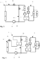
- the figure 1 shows a thermal management circuit 1 for a motor vehicle comprising a refrigerant fluid loop A in which circulates a refrigerant fluid, for example R134a.
- the first expansion device is controlled by measuring a temperature of the refrigerant fluid at the outlet of the third heat exchanger 11.
- the first expansion device 21 may for example be a thermostatic expansion valve, the thermostatic bulb of which is disposed at the outlet of the third heat exchanger 11.
- other types of expansion device by example an electronic expansion valve connected to a temperature sensor placed at the outlet of the third heat exchanger 11.
- the refrigerant fluid loop A further comprises a bypass branch B connecting the refrigerant fluid outlet of the second heat exchanger 9 to the refrigerant fluid inlet of the first heat exchanger 5.
- This bypass branch B comprises a second control device. expansion 22 controlled by measuring a temperature, called intermediate temperature, of the refrigerant at the outlet of the first heat exchanger 5.
- the second expansion device 22 can be for example a thermostatic expansion valve, the thermostatic bulb of which is disposed at the outlet of the first heat exchanger 5.
- other types of expansion device for example an electronic expansion valve connected to a temperature sensor disposed at the outlet of the first heat exchanger. heat 5.
- the bypass branch B more specifically connects a first junction point 31 and a second junction point 32.
- the first junction point 31 is arranged, in the direction of circulation of the refrigerant fluid, downstream of the second heat exchanger 9, between said second heat exchanger 9 and the first expansion device 21.
- the second junction point 32 is for its part disposed, in the direction of circulation of the refrigerant fluid, downstream of the first compressor 3, between said first compressor 3 and the first heat exchanger 5.
- the refrigerant fluid loop A may in particular include an internal heat exchanger 13 (also known by the acronym IHX for “internai heat exchanger”) which allows heat exchange between the refrigerant fluid at the outlet of the second heat exchanger 9 with the refrigerant at the outlet of the second expansion device 22.
- the IHX 13 comprises a first refrigerant fluid inlet disposed downstream of the second expansion device 22.
- the refrigerant entering the IHX 13 via this first refrigerant fluid inlet emerges in bypass branch B upstream of the second junction point 32.
- the IHX 13 also includes a second refrigerant fluid inlet disposed downstream of the first junction point 31, between said junction point 31 and the first expansion device 21.
- the refrigerant fluid entering the IHX 13 via this second refrigerant fluid inlet exits upstream of the first expansion device 21.
- This IHX 13 notably allows an improvement in the performance coefficient of the thermal management circuit 1 .
- the thermal management circuit 1 comprises a device for redirecting the refrigerant fluid from the second heat exchanger 9 to the first expansion device 21 and / or to the second expansion device 22 of the bypass branch B.
- This refrigerant fluid redirection device can be produced by various means that can be controlled by an electronic control unit on board the motor vehicle.
- a means may be a shut-off valve (not shown) arranged downstream of the first junction point 31, between said first junction point 31 and the first expansion device 21, or else arranged upstream of the second junction point 32, between the first expansion device 21 and said second junction point 32.
- Another means may be that the first expansion device 21 includes a stop function and therefore that it is able to block the flow of refrigerant fluid.
- a means may also be a shutdown of the first compressor 3 which thus prevents the circulation of the refrigerant fluid between the first 31 and second 32 junction points in the branch of the thermal management circuit comprising the first expansion device 21.
- the second heat exchanger 9 mainly plays the role of a condenser and the third heat exchanger 11 mainly plays the role of an evaporator.
- the first heat exchanger 5 may for its part be a charge air cooler which passes through the charge air from a turbocharger and intended for the heat engine.
- the first heat exchanger 5 can be a bifluid heat exchanger connected simultaneously to the refrigerant fluid loop A and to a heat transfer fluid loop C inside which circulates a heat transfer fluid, for example glycol water.
- the heat transfer fluid loop C may in particular include a pump 51 and a fourth heat exchanger 52 which may be a charge air cooler.
- the heat transfer fluid loop C can also include a fifth 53 and a sixth 54 heat exchangers which can be respectively placed in contact with the powertrain and the power electronics of a hybrid motor vehicle.
- the fifth 53 and sixth 54 heat exchangers can be in parallel with one another, that is to say that they share the heat transfer fluid coming from the same source.
- the fifth 53 and sixth 54 heat exchangers are arranged, in the direction of circulation of the heat transfer fluid, downstream of the first heat exchanger 5 and they are both connected to the refrigerant outlet of said first heat exchanger 5.
- the fourth heat exchanger 52 is for its part arranged, in the direction of circulation of the coolant, upstream of the first heat exchanger 5 and downstream of the fifth 53 and sixth 54 heat exchangers. This arrangement is explained by the fact that the fourth heat exchanger 52 is the heat exchanger of the heat transfer fluid loop C which has the most heat to dissipate compared to the fifth 53 and sixth 54 heat exchangers.
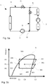
- the present invention also relates to a method of operating the thermal management circuit 1 according to different operating modes and variants illustrated in figures 5a to 8 .
- the direction of circulation of the refrigerant fluid is represented by arrows.
- the curve S corresponds to the saturation curve of the refrigerant fluid, in this case of R134a.
- the refrigerant fluids coming from the first compressor 3 and from the bypass branch B mix upstream from the first heat exchanger 5 before passing through it and joining the second compressor 7.
- the device for redirecting the refrigerant fluid coming from the second heat exchanger 9 allows the refrigerant fluid to circulate in the first expansion device 21 and in the second expansion device 22 of the bypass branch B.
- the second expansion device 22 is controlled by the intermediate temperature at the outlet of the first heat exchanger.
- the quantity of coolant passing through the branch of bypass B may vary depending on the opening of the second trigger 22.
- the figure 5b shows a pressure / enthalpy diagram of a first variant of the first mode of operation where the thermal management circuit 1 operates as an air conditioning circuit, i.e. it cools an air flow intended for the passenger compartment via the third heat exchanger 11 and also makes it possible to dissipate a large quantity of heat from the first heat exchanger 5. This can for example be the case when the internal combustion engine is under high demand and the user has switched on the function. air conditioning of the motor vehicle.
- the refrigerant fluid in the gaseous state at the outlet of the first heat exchanger 5 passes through the second compressor 7 and passes from a first pressure P1 to a second pressure P2 while compressing, as illustrated by arrow 700.
- the refrigerant fluid then passes through the second heat exchanger 9 in which it dissipates heat and loses enthalpy by transferring it to a flow of air outside the motor vehicle. Due to this loss of enthalpy, the refrigerant fluid passes through its saturation curve S a first time to pass into a more liquid gas mixture state and a second time to pass into a liquid state.
- the two refrigerant fluid portions mix and the refrigerant fluid reaches an enthalpy E3 illustrated by point 320.
- the intermediate temperature of the refrigerant fluid leaving the first heat exchanger 5 is high.
- This intermediate temperature influences the second expansion device 22 which allows the passage of a large proportion of refrigerant fluid in the bypass branch B.
- the proportion of refrigerant fluid passing through bypass branch B is greater than 50%, or even greater than 70%.
- the enthalpy E3 of the refrigerant at the junction point 32 will be close to the enthalpy E1 and therefore relatively low at the inlet of the first heat exchanger 5. Since the enthalpy E3 of the refrigerant entering the first heat exchanger 5 is relatively low, said refrigerant passing through the first heat exchanger 5 can absorb a large amount of enthalpy and strongly cool the charge air or the coolant of a loop of coolant C, as shown by arrow 500. The coolant, by gaining enthalpy, again cuts its saturation curve S and goes from a more liquid gas state to a gaseous state.
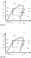
- the thermal management circuit 1 also functions as an air conditioning circuit and makes it possible to dissipate a moderate quantity of heat coming from the first heat exchanger 5. This can for example be the case when the internal combustion engine is weakly stressed and that the user has turned on the air conditioning function of the motor vehicle.
- the intermediate temperature at the outlet of the first heat exchanger 5 is relatively moderate (at least compared to that of the first variant of the first mode of operation).
- this intermediate temperature influences the second expansion device 22, which allows a moderate proportion of refrigerant fluid to pass into the bypass branch B.
- the proportion of refrigerant passing through the bypass branch B is of the order of 20 to 30%.
- the enthalpy E3 of the refrigerant at the junction point 32 will be close to the enthalpy E2 and therefore relatively moderate at the inlet of the first heat exchanger 5.
- heat 5 is relatively moderate, said refrigerant by passing through the first heat exchanger 5 can absorb only a moderate amount of enthalpy and moderately cool the charge air or coolant from a loop of coolant C, as shown the arrow 500.
- the refrigerant, gaining enthalpy again cuts its saturation curve S and passes from a more liquid gas state to a gaseous state.
- the thermal management circuit 1 also operates as an air conditioning circuit and does not allow heat from the first heat exchanger 5 to be dissipated. This may for example be the case when the internal combustion engine is not or little used, and the user has turned on the air conditioning function of the motor vehicle, for example when the vehicle is stationary.
- the intermediate temperature at the outlet of the first heat exchanger 5 is relatively low (at least compared to that of the first and second variants of the first mode of operation).
- this intermediate temperature influences the second expansion device 22 which allows the passage of a small proportion of refrigerant fluid in the bypass branch B.
- the proportion of refrigerant passing through the bypass branch B is less than 10%, or even less than 5%.
- the enthalpy E3 of the refrigerant at the junction point 32 will be very close to the enthalpy E2 and therefore relatively high at the inlet of the first heat exchanger 5.
- said coolant passing through the first heat exchanger 5 cannot absorb enthalpy and cool the charge air or the coolant from a coolant loop C. This is shown by 'no arrow 500 on the figure 5d .
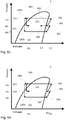
- the first operating mode can also operate when the thermal management circuit 1 comprises an IHX 13.
- the circulation of the refrigerant fluid is identical to that illustrated in figure 5a with the difference that at the outlet of the first junction point 31, the refrigerant fluid passes through the IHX 13 before joining the first expansion device 21 and that at the output of the second expansion device 22, the refrigerant passing through the branch of bypass B passes through IHX 13 before reaching the second junction 32.
- IHX 13 The influence of IHX 13 can be seen on the pressure / enthalpy diagrams of the figures 6b to 6d , corresponding respectively to the first, second and third variants of the first mode of operation.
- the IHX 13 allows a reduction in the enthalpy of the refrigerant, illustrated by the arrow 130a, before it enters the first expansion device 21 by transferring part of this enthalpy to the refrigerant fluid downstream of the second expansion device 22. This increase in enthalpy is illustrated by the arrow 130b. Point 221 will then be shifted to the right and therefore its enthalpy E1 will be greater than that without IHX 13.
- the enthalpy variation illustrated by arrow 900 is then greater than that illustrated in figures 5b to 5c where there is no IHX 13.
- the IHX 13 allows an increase in cooling power and improves the coefficient of performance (or COP for "coefficient of performance") by reducing the enthalpy of the refrigerant before its entering the first expansion device 21 and transferring it to the refrigerant of the bypass branch B.
- the figure 7a shows a second mode of operation of the thermal management circuit 1.
- the refrigerant circulates successively in the second compressor 7 and in the second heat exchanger 9.
- all refrigerant fluid passes into the bypass branch B and passes through the second expansion device 22 where it experiences a loss of isenthalpic pressure.
- the refrigerant then passes through the first heat exchanger 5 before joining the second compressor 7.
- the device for redirecting the refrigerant fluid coming from the second heat exchanger 9 allows the refrigerant fluid to circulate only in the bypass branch B.
- the second expansion device 22 is controlled by the intermediate temperature at the outlet of the first heat exchanger 5.
- the quantity of refrigerant passing through the bypass branch B can vary depending on the opening of the second expansion device 22. This makes it possible to control the cooling of the charge air or heat transfer fluid from the heat transfer fluid loop C
- the figure 7b shows a pressure / enthalpy diagram of the second operating mode where the thermal management circuit 1 operates only as a cooling circuit in order to dissipate heat from the first heat exchanger 5. This can for example be the case when the engine internal combustion engine is activated and the user has turned off the air conditioning function of the motor vehicle.
- the refrigerant fluid in the gaseous state at the outlet from the first heat exchanger 5 passes through the second compressor 7 and passes from a first pressure P1 to a second pressure P2 as illustrated by arrow 700.
- the refrigerant then passes through the second heat exchanger 9 in which it dissipates heat and loses enthalpy by transferring it to a flow of air outside the motor vehicle. Due to this loss of enthalpy, the refrigerant fluid passes through its saturation curve S a first time to pass into a more liquid gas mixture state and a second time to pass into a liquid state.
- This second operating mode is useful in order to devote the thermal management circuit 1 completely to cooling the charge air or the coolant of the coolant loop C.
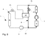
- This second operating mode can also operate when the thermal management circuit 1 comprises an IHX 13 as shown in figure 8 .
- the IHX 13 has no influence because it is crossed by a single flow of refrigerant.
- the thermal management circuit 1 by virtue of its architecture, allows cooling of the passenger compartment and / or of the charge air as required via direct cooling or via a cooling loop. coolant.
- a first compressor 3 and of a second compressor 7 it is possible to establish two pressure stages.
- the heat absorbed at the level of the third heat exchanger 11 and / or of the first heat exchanger 5 is for its part released into a flow of air outside the motor vehicle at the level of the second exchanger alone. heat 9.
Landscapes
- Engineering & Computer Science (AREA)
- Physics & Mathematics (AREA)
- Thermal Sciences (AREA)
- Mechanical Engineering (AREA)
- General Engineering & Computer Science (AREA)
- Air-Conditioning For Vehicles (AREA)
Claims (10)
- Wärmemanagementkreislauf (1) für ein Kraftfahrzeug, umfassend eine Kühlfluidschleife (A), in der ein Kühlfluid zirkuliert, wobei die Kühlfluidschleife (A) in der Zirkulationsrichtung des Kühlfluids Folgendes aufweist:- einen ersten Verdichter (3),- einen ersten Wärmetauscher (5), der stromabwärts des ersten Verdichters (3) angeordnet ist,- einen zweiten Verdichter (7),- einen zweiten Wärmetauscher (9), der stromabwärts des zweiten Verdichters (7) angeordnet ist, wobei der zweite Wärmetauscher (9) dazu vorgesehen ist, von einem Luftstrom von außerhalb des Kraftfahrzeugs durchströmt zu werden,- eine erste Expansionsvorrichtung (21), die stromabwärts des zweiten Wärmetauschers (9) angeordnet ist,- einen dritten Wärmetauscher (11), der stromabwärts der ersten Expansionsvorrichtung (21) angeordnet ist, wobei der dritte Wärmetauscher (11) dazu vorgesehen ist, von einem Innenluftstrom in Richtung des Fahrgastraums des Kraftfahrzeugs durchströmt zu werden,dadurch gekennzeichnet, dass die Kühlfluidschleife (A) ferner einen Bypass-Zweig (B) aufweist, der den Kühlfluidausgang des zweiten Wärmetauschers (9) mit dem Kühlfluideingang des erste Wärmetauschers (5) verbindet, wobei der Bypass-Zweig (B) eine zweite Expansionsvorrichtung (22) aufweist, die durch die Messung einer Zwischentemperatur des Kühlfluids am Ausgang des ersten Wärmetauschers (5) gesteuert wird.
- Wärmemanagementkreislauf (1) nach dem vorangehenden Anspruch, dadurch gekennzeichnet, dass er eine Vorrichtung zur Umleitung des vom zweiten Wärmetauscher (9) kommenden Kühlfluids zur ersten Expansionsvorrichtung (21) und/oder zur zweiten Expansionsvorrichtung (22) des Bypass-Zweigs (B) aufweist.
- Wärmemanagementkreislauf (1) nach einem der vorangehenden Ansprüche, dadurch gekennzeichnet, dass er eine Wärmeübertragungsfluidschleife (C) aufweist, die zumindest einen Ladeluftkühler aufweist, und dass der erste Wärmetauscher (5) ein Doppelfluidwärmetauscher ist, der mit der Wärmeübertragungsfluidschleife (C) verbunden ist.
- Wärmemanagementkreislauf (1) nach einem der Ansprüche 1 bis 3, dadurch gekennzeichnet, dass der erste Wärmetauscher (5) ein Ladeluftkühler ist.
- Indirekt reversibler Wärmemanagementkreislauf (1) nach einem der vorangehenden Ansprüche, dadurch gekennzeichnet, dass die zweite Expansionsvorrichtung (7) ein thermostatisches Expansionsventil ist, dessen Thermostatfühler am Ausgang des ersten Wärmetauschers (5) angeordnet ist.
- Wärmemanagementkreislauf (1) nach einem der vorangehenden Ansprüche, dadurch gekennzeichnet, dass er einen inneren Wärmetauscher (13) aufweist, wobei der innere Wärmetauscher (13) einen Wärmeaustausch zwischen dem Kühlfluid stromaufwärts der ersten Expansionsvorrichtung (21) mit dem Kühlfluid am Ausgang der zweiten Expansionsvorrichtung (22) ermöglicht.
- Verfahren zum Betreiben eines Wärmemanagementkreislaufs (1) nach einem der Ansprüche 1 bis 6 nach einer ersten Betriebsart, in der das Kühlfluid nacheinander im zweiten Verdichter (7) und im zweiten Wärmetauscher (9) zirkuliert und bei der am Ausgang des zweiten Wärmetauschers (9):- ein Teil des Kühlfluids in die erste Expansionsvorrichtung (21) gelangt, wo es einen Druckverlust erfährt, den dritten Wärmetauscher (11) durchströmt und durch den ersten Verdichter (3) gelangt,- ein weiterer Teil des Kühlfluids in den Bypass-Zweig (B) gelangt und die zweite Expansionsvorrichtung (22) durchströmt, wo es einen Druckverlust erfährt,wobei sich die Kühlfluide aus dem ersten Verdichter (3) und dem Bypass-Zweig (B) stromaufwärts des ersten Wärmetauschers (5) mischen, bevor sie diesen durchqueren und zum zweiten Verdichter (7) gelangen.
- Betriebsverfahren nach dem vorangehenden Anspruch und bei dem der Wärmemanagementkreislauf nach Anspruch 6 ist, wobei das Kühlfluid stromaufwärts der ersten Expansionsvorrichtung (21) den inneren Wärmetauscher (13) durchströmt, bevor es den dritten Wärmetauscher (11) erreicht, und das Kühlfluid am Ausgang der zweiten Expansionsvorrichtung (22) ebenfalls den inneren Wärmetauscher (13) durchströmt, bevor es aus dem Bypass-Zweig (B) austritt.
- Verfahren zum Betreiben eines Wärmemanagementkreislaufs (1) nach einem der Ansprüche 1 bis 6 nach einer zweiten Betriebsart, bei der das Kühlfluid nacheinander im zweiten Verdichter (7) und im zweiten Wärmetauscher (9) zirkuliert und bei dem am Ausgang des zweiten Wärmetauschers (9) das gesamte Kühlfluid in den Bypass-Zweig (B) strömt und die zweite Expansionsvorrichtung (22) durchströmt, wo es einen Druckverlust erfährt, wobei das Kühlfluid anschließend den ersten Wärmetauscher (5) durchströmt, bevor es zum zweiten Verdichter (7) gelangt.
- Betriebsverfahren nach einem der Ansprüche 7 bis 9 dadurch gekennzeichnet, dass die Menge des den Bypass-Zweig durchströmenden Kühlfluids von der Öffnung der zweiten Expansionsvorrichtung (22), die durch die Zwischentemperatur des Kühlfluids am Ausgang des ersten Wärmetauschers (5) gesteuert wird, abhängt.
Applications Claiming Priority (2)
| Application Number | Priority Date | Filing Date | Title |
|---|---|---|---|
| FR1658674A FR3056289B1 (fr) | 2016-09-16 | 2016-09-16 | Circuit de gestion thermique pour vehicule automobile |
| PCT/FR2017/052475 WO2018051038A1 (fr) | 2016-09-16 | 2017-09-15 | Circuit de gestion thermique pour vehicule automobile |
Publications (2)
| Publication Number | Publication Date |
|---|---|
| EP3513134A1 EP3513134A1 (de) | 2019-07-24 |
| EP3513134B1 true EP3513134B1 (de) | 2020-08-12 |
Family
ID=57680384
Family Applications (1)
| Application Number | Title | Priority Date | Filing Date |
|---|---|---|---|
| EP17780818.5A Active EP3513134B1 (de) | 2016-09-16 | 2017-09-15 | Wärmeverwaltungsschaltung für kraftfahrzeug |
Country Status (4)
| Country | Link |
|---|---|
| EP (1) | EP3513134B1 (de) |
| CN (1) | CN109791004B (de) |
| FR (1) | FR3056289B1 (de) |
| WO (1) | WO2018051038A1 (de) |
Cited By (1)
| Publication number | Priority date | Publication date | Assignee | Title |
|---|---|---|---|---|
| WO2023194473A1 (de) * | 2022-04-07 | 2023-10-12 | Efficient Energy Gmbh | Wärmepumpe |
Families Citing this family (5)
| Publication number | Priority date | Publication date | Assignee | Title |
|---|---|---|---|---|
| FR3088705B1 (fr) * | 2018-11-16 | 2020-11-27 | Valeo Systemes Thermiques | Dispositif de gestion thermique inversible d'un vehicule automobile |
| FR3101281B1 (fr) * | 2019-09-26 | 2022-06-24 | Valeo Systemes Thermiques | Systeme de traitement thermique destine a un vehicule automobile |
| FR3102552B1 (fr) * | 2019-10-29 | 2022-07-29 | Valeo Systemes Thermiques | Dispositif d’échange d’énergie calorifique comportant deux échangeurs de chaleur à plaques |
| FR3112720B1 (fr) * | 2020-07-27 | 2022-09-02 | Valeo Systemes Thermiques | Module de refroidissement pour véhicule automobile électrique ou hybride |
| FR3116766B1 (fr) | 2020-12-02 | 2022-10-14 | Valeo Systemes Thermiques | Circuit de fluide réfrigérant comprenant une branche de contournement d’un accumulateur |
Family Cites Families (9)
| Publication number | Priority date | Publication date | Assignee | Title |
|---|---|---|---|---|
| JP3600163B2 (ja) * | 2001-02-13 | 2004-12-08 | 三洋電機株式会社 | 車載空気調和機 |
| FR2830926B1 (fr) * | 2001-10-12 | 2004-04-02 | Peugeot Citroen Automobiles Sa | Dispositif de regulation thermique pour vehicule automobile, notamment de type electrique ou hybride |
| JP2003254661A (ja) * | 2002-02-27 | 2003-09-10 | Toshiba Corp | 冷蔵庫 |
| JP4569508B2 (ja) * | 2006-03-31 | 2010-10-27 | 株式会社デンソー | 超臨界サイクル及び冷凍サイクルに用いられる膨張弁 |
| WO2008105868A2 (en) * | 2007-02-26 | 2008-09-04 | Carrier Corporation | Economized refrigerant system utilizing expander with intermediate pressure port |
| FR2958327B1 (fr) * | 2010-03-31 | 2012-03-23 | Valeo Sys Controle Moteur Sas | Dispositif de refroidissement pour un circuit de recirculation de gaz d'echappement d'un moteur, notamment de vehicule automobile. |
| CN104661842A (zh) * | 2012-09-20 | 2015-05-27 | 冷王公司 | 电动运输制冷系统 |
| FR3015012B1 (fr) * | 2013-12-16 | 2016-09-02 | Valeo Systemes Thermiques | Dispositif de conditionnement thermique d'un habitacle et/ou d'un organe d'un vehicule automobile |
| FR3030700B1 (fr) * | 2014-12-18 | 2019-03-22 | Valeo Systemes Thermiques | Circuit de climatisation de vehicule automobile |
-
2016
- 2016-09-16 FR FR1658674A patent/FR3056289B1/fr not_active Expired - Fee Related
-
2017
- 2017-09-15 EP EP17780818.5A patent/EP3513134B1/de active Active
- 2017-09-15 CN CN201780056291.8A patent/CN109791004B/zh active Active
- 2017-09-15 WO PCT/FR2017/052475 patent/WO2018051038A1/fr not_active Ceased
Non-Patent Citations (1)
| Title |
|---|
| None * |
Cited By (1)
| Publication number | Priority date | Publication date | Assignee | Title |
|---|---|---|---|---|
| WO2023194473A1 (de) * | 2022-04-07 | 2023-10-12 | Efficient Energy Gmbh | Wärmepumpe |
Also Published As
| Publication number | Publication date |
|---|---|
| EP3513134A1 (de) | 2019-07-24 |
| WO2018051038A1 (fr) | 2018-03-22 |
| CN109791004B (zh) | 2021-04-06 |
| FR3056289B1 (fr) | 2018-09-28 |
| CN109791004A (zh) | 2019-05-21 |
| FR3056289A1 (fr) | 2018-03-23 |
Similar Documents
| Publication | Publication Date | Title |
|---|---|---|
| EP3513134B1 (de) | Wärmeverwaltungsschaltung für kraftfahrzeug | |
| EP3465025B1 (de) | Klimaanlagenkreislauf eines kraftfahrzeugs | |
| EP3606774B1 (de) | Indirekter reversibler klimatisierungskreislauf für ein kraftfahrzeug und zugehöriges betriebsverfahren | |
| EP3924673A1 (de) | Vorrichtung zur thermischen verwaltung eines elektrischen oder hybriden kraftfahrzeugs | |
| EP3496964B1 (de) | Indirekter reversibler klimaanlagenkreislauf für ein kraftfahrzeug und zugehöriges betriebsverfahren | |
| EP3914866B1 (de) | Klimaanlage eines kraftfahrzeugs und zugehöriges verwaltungsverfahren | |
| EP3924674A1 (de) | Temperatursteuerungsvorrichtung für ein elektrisches oder hybrides kraftfahrzeug | |
| WO2018211200A1 (fr) | Circuit de climatisation inversible indirect de vehicule automobile et procede de de gestion en mode pompe a chaleur | |
| WO2021116564A1 (fr) | Dispositif de gestion thermique inversible | |
| EP3263374A1 (de) | Reversibler klimatisierungskreislauf für ein kraftfahrzeug, und entsprechende funktionsweisen | |
| FR3033290A1 (fr) | Circuit de climatisation de vehicule automobile | |
| WO2020260814A1 (fr) | Procede de gestion d'un dispositif de gestion thermique pour vehicule automobile | |
| WO2020099798A1 (fr) | Dispositif de gestion thermique inversible d'un vehicule automobile | |
| EP3507114B1 (de) | Indirekter reversibler klimatisierungskreislauf für ein kraftfahrzeug und zugehöriges betriebsverfahren | |
| EP3433550B1 (de) | Klimaanlagenkreislauf eines kraftfahrzeugs | |
| FR3092162A1 (fr) | Circuit de climatisation de véhicule automobile et procédé de gestion associé | |
| WO2021152235A1 (fr) | Dispositif de gestion thermique pour vehicule automobile | |
| WO2020165513A1 (fr) | Dispositif de gestion thermique de véhicule automobile électrique ou hybride | |
| WO2020234057A1 (fr) | Dispositif de gestion thermique avec vanne de régulation de pression d'évaporation | |
| WO2018211199A1 (fr) | Circuit de climatisation inversible indirect de vehicule automobile et procede de gestion en mode de pompe a chaleur | |
| WO2017207038A1 (fr) | Système de gestion thermique d'air d'admission d'un moteur thermique suralimenté | |
| WO2023072586A1 (fr) | Systeme de gestion thermique pour vehicule hybride ou electrique | |
| FR3100607A1 (fr) | Dispositif de gestion thermique inversible d’un véhicule automobile comportant un module de redirection du fluide réfrigérant et module de redirection correspondant | |
| WO2023031149A1 (fr) | Dispositif de gestion thermique des batteries pour véhicule électrique ou hybride |
Legal Events
| Date | Code | Title | Description |
|---|---|---|---|
| STAA | Information on the status of an ep patent application or granted ep patent |
Free format text: STATUS: UNKNOWN |
|
| STAA | Information on the status of an ep patent application or granted ep patent |
Free format text: STATUS: THE INTERNATIONAL PUBLICATION HAS BEEN MADE |
|
| PUAI | Public reference made under article 153(3) epc to a published international application that has entered the european phase |
Free format text: ORIGINAL CODE: 0009012 |
|
| STAA | Information on the status of an ep patent application or granted ep patent |
Free format text: STATUS: REQUEST FOR EXAMINATION WAS MADE |
|
| 17P | Request for examination filed |
Effective date: 20190401 |
|
| AK | Designated contracting states |
Kind code of ref document: A1 Designated state(s): AL AT BE BG CH CY CZ DE DK EE ES FI FR GB GR HR HU IE IS IT LI LT LU LV MC MK MT NL NO PL PT RO RS SE SI SK SM TR |
|
| AX | Request for extension of the european patent |
Extension state: BA ME |
|
| DAV | Request for validation of the european patent (deleted) | ||
| DAX | Request for extension of the european patent (deleted) | ||
| GRAP | Despatch of communication of intention to grant a patent |
Free format text: ORIGINAL CODE: EPIDOSNIGR1 |
|
| STAA | Information on the status of an ep patent application or granted ep patent |
Free format text: STATUS: GRANT OF PATENT IS INTENDED |
|
| INTG | Intention to grant announced |
Effective date: 20200401 |
|
| GRAS | Grant fee paid |
Free format text: ORIGINAL CODE: EPIDOSNIGR3 |
|
| GRAA | (expected) grant |
Free format text: ORIGINAL CODE: 0009210 |
|
| STAA | Information on the status of an ep patent application or granted ep patent |
Free format text: STATUS: THE PATENT HAS BEEN GRANTED |
|
| AK | Designated contracting states |
Kind code of ref document: B1 Designated state(s): AL AT BE BG CH CY CZ DE DK EE ES FI FR GB GR HR HU IE IS IT LI LT LU LV MC MK MT NL NO PL PT RO RS SE SI SK SM TR |
|
| REG | Reference to a national code |
Ref country code: CH Ref legal event code: EP |
|
| REG | Reference to a national code |
Ref country code: IE Ref legal event code: FG4D Free format text: LANGUAGE OF EP DOCUMENT: FRENCH |
|
| REG | Reference to a national code |
Ref country code: DE Ref legal event code: R096 Ref document number: 602017021629 Country of ref document: DE |
|
| REG | Reference to a national code |
Ref country code: AT Ref legal event code: REF Ref document number: 1301941 Country of ref document: AT Kind code of ref document: T Effective date: 20200915 |
|
| REG | Reference to a national code |
Ref country code: LT Ref legal event code: MG4D |
|
| REG | Reference to a national code |
Ref country code: NL Ref legal event code: MP Effective date: 20200812 |
|
| PG25 | Lapsed in a contracting state [announced via postgrant information from national office to epo] |
Ref country code: SE Free format text: LAPSE BECAUSE OF FAILURE TO SUBMIT A TRANSLATION OF THE DESCRIPTION OR TO PAY THE FEE WITHIN THE PRESCRIBED TIME-LIMIT Effective date: 20200812 Ref country code: NO Free format text: LAPSE BECAUSE OF FAILURE TO SUBMIT A TRANSLATION OF THE DESCRIPTION OR TO PAY THE FEE WITHIN THE PRESCRIBED TIME-LIMIT Effective date: 20201112 Ref country code: BG Free format text: LAPSE BECAUSE OF FAILURE TO SUBMIT A TRANSLATION OF THE DESCRIPTION OR TO PAY THE FEE WITHIN THE PRESCRIBED TIME-LIMIT Effective date: 20201112 Ref country code: GR Free format text: LAPSE BECAUSE OF FAILURE TO SUBMIT A TRANSLATION OF THE DESCRIPTION OR TO PAY THE FEE WITHIN THE PRESCRIBED TIME-LIMIT Effective date: 20201113 Ref country code: LT Free format text: LAPSE BECAUSE OF FAILURE TO SUBMIT A TRANSLATION OF THE DESCRIPTION OR TO PAY THE FEE WITHIN THE PRESCRIBED TIME-LIMIT Effective date: 20200812 Ref country code: FI Free format text: LAPSE BECAUSE OF FAILURE TO SUBMIT A TRANSLATION OF THE DESCRIPTION OR TO PAY THE FEE WITHIN THE PRESCRIBED TIME-LIMIT Effective date: 20200812 Ref country code: HR Free format text: LAPSE BECAUSE OF FAILURE TO SUBMIT A TRANSLATION OF THE DESCRIPTION OR TO PAY THE FEE WITHIN THE PRESCRIBED TIME-LIMIT Effective date: 20200812 |
|
| REG | Reference to a national code |
Ref country code: AT Ref legal event code: MK05 Ref document number: 1301941 Country of ref document: AT Kind code of ref document: T Effective date: 20200812 |
|
| PG25 | Lapsed in a contracting state [announced via postgrant information from national office to epo] |
Ref country code: RS Free format text: LAPSE BECAUSE OF FAILURE TO SUBMIT A TRANSLATION OF THE DESCRIPTION OR TO PAY THE FEE WITHIN THE PRESCRIBED TIME-LIMIT Effective date: 20200812 Ref country code: LV Free format text: LAPSE BECAUSE OF FAILURE TO SUBMIT A TRANSLATION OF THE DESCRIPTION OR TO PAY THE FEE WITHIN THE PRESCRIBED TIME-LIMIT Effective date: 20200812 Ref country code: PL Free format text: LAPSE BECAUSE OF FAILURE TO SUBMIT A TRANSLATION OF THE DESCRIPTION OR TO PAY THE FEE WITHIN THE PRESCRIBED TIME-LIMIT Effective date: 20200812 Ref country code: NL Free format text: LAPSE BECAUSE OF FAILURE TO SUBMIT A TRANSLATION OF THE DESCRIPTION OR TO PAY THE FEE WITHIN THE PRESCRIBED TIME-LIMIT Effective date: 20200812 Ref country code: IS Free format text: LAPSE BECAUSE OF FAILURE TO SUBMIT A TRANSLATION OF THE DESCRIPTION OR TO PAY THE FEE WITHIN THE PRESCRIBED TIME-LIMIT Effective date: 20201212 |
|
| PG25 | Lapsed in a contracting state [announced via postgrant information from national office to epo] |
Ref country code: SM Free format text: LAPSE BECAUSE OF FAILURE TO SUBMIT A TRANSLATION OF THE DESCRIPTION OR TO PAY THE FEE WITHIN THE PRESCRIBED TIME-LIMIT Effective date: 20200812 Ref country code: CZ Free format text: LAPSE BECAUSE OF FAILURE TO SUBMIT A TRANSLATION OF THE DESCRIPTION OR TO PAY THE FEE WITHIN THE PRESCRIBED TIME-LIMIT Effective date: 20200812 Ref country code: DK Free format text: LAPSE BECAUSE OF FAILURE TO SUBMIT A TRANSLATION OF THE DESCRIPTION OR TO PAY THE FEE WITHIN THE PRESCRIBED TIME-LIMIT Effective date: 20200812 Ref country code: RO Free format text: LAPSE BECAUSE OF FAILURE TO SUBMIT A TRANSLATION OF THE DESCRIPTION OR TO PAY THE FEE WITHIN THE PRESCRIBED TIME-LIMIT Effective date: 20200812 Ref country code: EE Free format text: LAPSE BECAUSE OF FAILURE TO SUBMIT A TRANSLATION OF THE DESCRIPTION OR TO PAY THE FEE WITHIN THE PRESCRIBED TIME-LIMIT Effective date: 20200812 |
|
| REG | Reference to a national code |
Ref country code: CH Ref legal event code: PL |
|
| REG | Reference to a national code |
Ref country code: DE Ref legal event code: R097 Ref document number: 602017021629 Country of ref document: DE |
|
| PG25 | Lapsed in a contracting state [announced via postgrant information from national office to epo] |
Ref country code: MC Free format text: LAPSE BECAUSE OF FAILURE TO SUBMIT A TRANSLATION OF THE DESCRIPTION OR TO PAY THE FEE WITHIN THE PRESCRIBED TIME-LIMIT Effective date: 20200812 Ref country code: ES Free format text: LAPSE BECAUSE OF FAILURE TO SUBMIT A TRANSLATION OF THE DESCRIPTION OR TO PAY THE FEE WITHIN THE PRESCRIBED TIME-LIMIT Effective date: 20200812 Ref country code: AL Free format text: LAPSE BECAUSE OF FAILURE TO SUBMIT A TRANSLATION OF THE DESCRIPTION OR TO PAY THE FEE WITHIN THE PRESCRIBED TIME-LIMIT Effective date: 20200812 Ref country code: AT Free format text: LAPSE BECAUSE OF FAILURE TO SUBMIT A TRANSLATION OF THE DESCRIPTION OR TO PAY THE FEE WITHIN THE PRESCRIBED TIME-LIMIT Effective date: 20200812 |
|
| PLBE | No opposition filed within time limit |
Free format text: ORIGINAL CODE: 0009261 |
|
| REG | Reference to a national code |
Ref country code: BE Ref legal event code: MM Effective date: 20200930 |
|
| STAA | Information on the status of an ep patent application or granted ep patent |
Free format text: STATUS: NO OPPOSITION FILED WITHIN TIME LIMIT |
|
| PG25 | Lapsed in a contracting state [announced via postgrant information from national office to epo] |
Ref country code: LU Free format text: LAPSE BECAUSE OF NON-PAYMENT OF DUE FEES Effective date: 20200915 Ref country code: SK Free format text: LAPSE BECAUSE OF FAILURE TO SUBMIT A TRANSLATION OF THE DESCRIPTION OR TO PAY THE FEE WITHIN THE PRESCRIBED TIME-LIMIT Effective date: 20200812 |
|
| 26N | No opposition filed |
Effective date: 20210514 |
|
| PG25 | Lapsed in a contracting state [announced via postgrant information from national office to epo] |
Ref country code: IT Free format text: LAPSE BECAUSE OF FAILURE TO SUBMIT A TRANSLATION OF THE DESCRIPTION OR TO PAY THE FEE WITHIN THE PRESCRIBED TIME-LIMIT Effective date: 20200812 |
|
| PG25 | Lapsed in a contracting state [announced via postgrant information from national office to epo] |
Ref country code: BE Free format text: LAPSE BECAUSE OF NON-PAYMENT OF DUE FEES Effective date: 20200930 Ref country code: CH Free format text: LAPSE BECAUSE OF NON-PAYMENT OF DUE FEES Effective date: 20200930 Ref country code: SI Free format text: LAPSE BECAUSE OF FAILURE TO SUBMIT A TRANSLATION OF THE DESCRIPTION OR TO PAY THE FEE WITHIN THE PRESCRIBED TIME-LIMIT Effective date: 20200812 Ref country code: IE Free format text: LAPSE BECAUSE OF NON-PAYMENT OF DUE FEES Effective date: 20200915 Ref country code: LI Free format text: LAPSE BECAUSE OF NON-PAYMENT OF DUE FEES Effective date: 20200930 |
|
| GBPC | Gb: european patent ceased through non-payment of renewal fee |
Effective date: 20210915 |
|
| PG25 | Lapsed in a contracting state [announced via postgrant information from national office to epo] |
Ref country code: TR Free format text: LAPSE BECAUSE OF FAILURE TO SUBMIT A TRANSLATION OF THE DESCRIPTION OR TO PAY THE FEE WITHIN THE PRESCRIBED TIME-LIMIT Effective date: 20200812 Ref country code: MT Free format text: LAPSE BECAUSE OF FAILURE TO SUBMIT A TRANSLATION OF THE DESCRIPTION OR TO PAY THE FEE WITHIN THE PRESCRIBED TIME-LIMIT Effective date: 20200812 Ref country code: CY Free format text: LAPSE BECAUSE OF FAILURE TO SUBMIT A TRANSLATION OF THE DESCRIPTION OR TO PAY THE FEE WITHIN THE PRESCRIBED TIME-LIMIT Effective date: 20200812 |
|
| PG25 | Lapsed in a contracting state [announced via postgrant information from national office to epo] |
Ref country code: MK Free format text: LAPSE BECAUSE OF FAILURE TO SUBMIT A TRANSLATION OF THE DESCRIPTION OR TO PAY THE FEE WITHIN THE PRESCRIBED TIME-LIMIT Effective date: 20200812 |
|
| PG25 | Lapsed in a contracting state [announced via postgrant information from national office to epo] |
Ref country code: PT Free format text: LAPSE BECAUSE OF FAILURE TO SUBMIT A TRANSLATION OF THE DESCRIPTION OR TO PAY THE FEE WITHIN THE PRESCRIBED TIME-LIMIT Effective date: 20200812 Ref country code: GB Free format text: LAPSE BECAUSE OF NON-PAYMENT OF DUE FEES Effective date: 20210915 |
|
| P01 | Opt-out of the competence of the unified patent court (upc) registered |
Effective date: 20230528 |
|
| PGFP | Annual fee paid to national office [announced via postgrant information from national office to epo] |
Ref country code: DE Payment date: 20250916 Year of fee payment: 9 |
|
| PGFP | Annual fee paid to national office [announced via postgrant information from national office to epo] |
Ref country code: FR Payment date: 20250929 Year of fee payment: 9 |