EP3433550B1 - Motor vehicle air-conditioning circuit - Google Patents
Motor vehicle air-conditioning circuit Download PDFInfo
- Publication number
- EP3433550B1 EP3433550B1 EP17711251.3A EP17711251A EP3433550B1 EP 3433550 B1 EP3433550 B1 EP 3433550B1 EP 17711251 A EP17711251 A EP 17711251A EP 3433550 B1 EP3433550 B1 EP 3433550B1
- Authority
- EP
- European Patent Office
- Prior art keywords
- refrigerant
- heat exchanger
- ejector
- compressor
- conditioning circuit
- Prior art date
- Legal status (The legal status is an assumption and is not a legal conclusion. Google has not performed a legal analysis and makes no representation as to the accuracy of the status listed.)
- Active
Links
Images


Classifications
-
- F—MECHANICAL ENGINEERING; LIGHTING; HEATING; WEAPONS; BLASTING
- F25—REFRIGERATION OR COOLING; COMBINED HEATING AND REFRIGERATION SYSTEMS; HEAT PUMP SYSTEMS; MANUFACTURE OR STORAGE OF ICE; LIQUEFACTION SOLIDIFICATION OF GASES
- F25B—REFRIGERATION MACHINES, PLANTS OR SYSTEMS; COMBINED HEATING AND REFRIGERATION SYSTEMS; HEAT PUMP SYSTEMS
- F25B41/00—Fluid-circulation arrangements
-
- F—MECHANICAL ENGINEERING; LIGHTING; HEATING; WEAPONS; BLASTING
- F25—REFRIGERATION OR COOLING; COMBINED HEATING AND REFRIGERATION SYSTEMS; HEAT PUMP SYSTEMS; MANUFACTURE OR STORAGE OF ICE; LIQUEFACTION SOLIDIFICATION OF GASES
- F25B—REFRIGERATION MACHINES, PLANTS OR SYSTEMS; COMBINED HEATING AND REFRIGERATION SYSTEMS; HEAT PUMP SYSTEMS
- F25B5/00—Compression machines, plants or systems, with several evaporator circuits, e.g. for varying refrigerating capacity
- F25B5/02—Compression machines, plants or systems, with several evaporator circuits, e.g. for varying refrigerating capacity arranged in parallel
-
- F—MECHANICAL ENGINEERING; LIGHTING; HEATING; WEAPONS; BLASTING
- F25—REFRIGERATION OR COOLING; COMBINED HEATING AND REFRIGERATION SYSTEMS; HEAT PUMP SYSTEMS; MANUFACTURE OR STORAGE OF ICE; LIQUEFACTION SOLIDIFICATION OF GASES
- F25B—REFRIGERATION MACHINES, PLANTS OR SYSTEMS; COMBINED HEATING AND REFRIGERATION SYSTEMS; HEAT PUMP SYSTEMS
- F25B5/00—Compression machines, plants or systems, with several evaporator circuits, e.g. for varying refrigerating capacity
- F25B5/04—Compression machines, plants or systems, with several evaporator circuits, e.g. for varying refrigerating capacity arranged in series
-
- B—PERFORMING OPERATIONS; TRANSPORTING
- B60—VEHICLES IN GENERAL
- B60H—ARRANGEMENTS OF HEATING, COOLING, VENTILATING OR OTHER AIR-TREATING DEVICES SPECIALLY ADAPTED FOR PASSENGER OR GOODS SPACES OF VEHICLES
- B60H1/00—Heating, cooling or ventilating [HVAC] devices
- B60H1/32—Cooling devices
- B60H2001/3286—Constructional features
- B60H2001/3298—Ejector-type refrigerant circuits
-
- F—MECHANICAL ENGINEERING; LIGHTING; HEATING; WEAPONS; BLASTING
- F25—REFRIGERATION OR COOLING; COMBINED HEATING AND REFRIGERATION SYSTEMS; HEAT PUMP SYSTEMS; MANUFACTURE OR STORAGE OF ICE; LIQUEFACTION SOLIDIFICATION OF GASES
- F25B—REFRIGERATION MACHINES, PLANTS OR SYSTEMS; COMBINED HEATING AND REFRIGERATION SYSTEMS; HEAT PUMP SYSTEMS
- F25B2341/00—Details of ejectors not being used as compression device; Details of flow restrictors or expansion valves
- F25B2341/001—Ejectors not being used as compression device
- F25B2341/0012—Ejectors with the cooled primary flow at high pressure
-
- F—MECHANICAL ENGINEERING; LIGHTING; HEATING; WEAPONS; BLASTING
- F25—REFRIGERATION OR COOLING; COMBINED HEATING AND REFRIGERATION SYSTEMS; HEAT PUMP SYSTEMS; MANUFACTURE OR STORAGE OF ICE; LIQUEFACTION SOLIDIFICATION OF GASES
- F25B—REFRIGERATION MACHINES, PLANTS OR SYSTEMS; COMBINED HEATING AND REFRIGERATION SYSTEMS; HEAT PUMP SYSTEMS
- F25B2400/00—General features or devices for refrigeration machines, plants or systems, combined heating and refrigeration systems or heat-pump systems, i.e. not limited to a particular subgroup of F25B
- F25B2400/04—Refrigeration circuit bypassing means
- F25B2400/0409—Refrigeration circuit bypassing means for the evaporator
-
- F—MECHANICAL ENGINEERING; LIGHTING; HEATING; WEAPONS; BLASTING
- F25—REFRIGERATION OR COOLING; COMBINED HEATING AND REFRIGERATION SYSTEMS; HEAT PUMP SYSTEMS; MANUFACTURE OR STORAGE OF ICE; LIQUEFACTION SOLIDIFICATION OF GASES
- F25B—REFRIGERATION MACHINES, PLANTS OR SYSTEMS; COMBINED HEATING AND REFRIGERATION SYSTEMS; HEAT PUMP SYSTEMS
- F25B2400/00—General features or devices for refrigeration machines, plants or systems, combined heating and refrigeration systems or heat-pump systems, i.e. not limited to a particular subgroup of F25B
- F25B2400/04—Refrigeration circuit bypassing means
- F25B2400/0411—Refrigeration circuit bypassing means for the expansion valve or capillary tube
-
- F—MECHANICAL ENGINEERING; LIGHTING; HEATING; WEAPONS; BLASTING
- F25—REFRIGERATION OR COOLING; COMBINED HEATING AND REFRIGERATION SYSTEMS; HEAT PUMP SYSTEMS; MANUFACTURE OR STORAGE OF ICE; LIQUEFACTION SOLIDIFICATION OF GASES
- F25B—REFRIGERATION MACHINES, PLANTS OR SYSTEMS; COMBINED HEATING AND REFRIGERATION SYSTEMS; HEAT PUMP SYSTEMS
- F25B2400/00—General features or devices for refrigeration machines, plants or systems, combined heating and refrigeration systems or heat-pump systems, i.e. not limited to a particular subgroup of F25B
- F25B2400/23—Separators
Definitions
- the invention relates to the field of motor vehicles and more particularly to a motor vehicle air conditioning circuit.
- a refrigerant fluid passes successively in a compressor, a condenser placed in contact with an air flow outside the motor vehicle to release heat, an expansion device and an evaporator placed in contact with an air flow inside the motor vehicle to cool it.
- the performance of an air conditioning circuit is generally retranscribed by a coefficient of performance (COP for "coefficient of perfomance" in English) which corresponds to the quotient between the heat returned, at the condenser, and the work provided, in particular by the compressor .
- COP coefficient of performance
- the liquid phase of the refrigerant fluid is redirected towards the evaporator and the gas phase of the refrigerant fluid is in turn redirected to the compressor.
- the document FR-A-2 936 596 discloses an air conditioning circuit according to the preamble of claim 1.
- One of the aims of the present invention is therefore to at least partially overcome the disadvantages of the prior art and to provide an improved air conditioning circuit.
- the air conditioning circuit comprises a refrigerant management and distribution device from the ejector to the bypass line and / or the phase separation device.
- the management and distribution device comprises a first stop valve disposed between the first junction point and the phase separation device.
- the management and distribution device comprises a second stop valve disposed on the bypass line.
- the management and distribution device comprises a variable opening valve disposed on the bypass line.
- the management and distribution device comprises a variable-rate three-way valve disposed at the first junction point.
- the third heat exchanger is intended to be traversed by the interior air flow to the passenger compartment of the motor vehicle.
- the third heat exchanger is placed upstream of the second heat exchanger in the direction of flow of the interior air flow to the passenger compartment of the motor vehicle.
- the air conditioning circuit comprises an internal heat exchanger allowing a heat exchange between the refrigerant at the outlet of the first heat exchanger and the refrigerant at the outlet of the phase separation device and / or of the third heat exchanger.
- the refrigerant fluid at the outlet of the first heat exchanger passes into the internal heat exchanger before reaching the ejector, the gaseous phase of the refrigerant at the outlet of the phase separation device and the coolant at the outlet of the third heat exchanger mixes before passing into the internal heat exchanger and then back to the compressor.
- the air conditioning circuit is configured to operate in a second mode of operation where the refrigerant passes successively in the compressor, the first heat exchanger, the ejector, the third heat exchanger of the bypass before returning to the compressor.
- the refrigerant at the outlet of the first heat exchanger passes into the internal heat exchanger before reaching the ejector and the refrigerant at the outlet of the third heat exchanger passes through the heat exchanger. internal heat exchanger before returning to the compressor.
- the refrigerant at the outlet of the first heat exchanger passes into the internal heat exchanger before reaching the ejector and the gaseous phase of the refrigerant at the outlet of the phase separation device passes through the internal heat exchanger before returning to the compressor.
- first element or second element as well as first parameter and second parameter or else first criterion and second criterion, etc.
- first criterion and second criterion etc.
- it is a simple indexing to differentiate and name elements or parameters or criteria close but not identical.
- This indexing does not imply a priority of one element, parameter or criterion with respect to another, and it is easy to interchange such denominations without departing from the scope of the present description.
- This indexing does not imply either an order in time for example to appreciate this or that criterion.
- placed upstream means that one element is placed before another relative to the direction of flow of a fluid.
- downstream means that one element is placed after another relative to the direction of fluid flow.
- the refrigerant may in particular be carbon dioxide known in the field of air conditioning circuit under the name R744.
- the bypass line A also comprises a third heat exchanger 17.
- the air conditioning circuit may also include an internal heat exchanger 21 (IHX for "internai heat exchanger") allowing a heat exchange between the refrigerant at the outlet of the first heat exchanger 5 and the refrigerant at the outlet of the separation device 9 and / or the third heat exchanger 17.
- IHX internal heat exchanger
- bypass line A and the third heat exchanger 17 allows the air conditioning circuit 1 to operate according to a first operating mode illustrated in FIG. figure 3a where the flow direction of the coolant is represented by arrows.
- Curve B represents the saturation curve of the refrigerant fluid.
- the refrigerant at the inlet of the compressor 3 is in the gas phase at a pressure p1a and has an enthalpy h1a.
- the refrigerant is compressed, illustrated by the arrow 300, passing through the compressor 3 and goes to a pressure p2a for enthalpy h2a.
- the refrigerant passes through the first heat exchanger 5 and undergoes a loss of enthalpy, illustrated by the arrow 500, due to the heat dissipation in the outside air flow 100 and its passage in the liquid phase.
- the refrigerant then passes from an enthalpy h2a to an enthalpy h3a, while remaining at a constant pressure p2a.
- the refrigerant then passes into the first inlet 7a of the ejector 7.
- the refrigerant undergoes a loss of pressure, illustrated by the arrow 70a and crosses the saturation curve B, which makes it pass into a state of liquid mixture more gas.
- the refrigerant is then recompressed in the ejector 7 to reach the outlet 7c of said ejector 7, illustrated by point 70c.
- the coolant is at the pressure p1a and has an enthalpy h4a greater than the previous enthalpy h3a.
- Part of the refrigerant then passes into the phase separation device 9, while the other part of the coolant passes into the bypass line A.
- the liquid phase of the refrigerant fluid is separated from the gas phase.
- the enthalpy of the coolant in the liquid phase at the second outlet 9c of the phase separation device 9 decreases to reach the saturation curve B and reach a value h5a. This decrease is illustrated by the arrow 90c.
- the refrigerant then flows into the expansion device 11 where it undergoes a relaxation, illustrated by the arrow 110, passing from the pressure p1a to the pressure p3a.
- the refrigerant then passes through the second heat exchanger 13 where it undergoes evaporation, illustrated by the arrow 130.
- the refrigerant during its passage through the second heat exchanger 13 absorbs energy heat of the interior air flow 200 and passes from the enthalpy h5a to the enthalpy h6a.
- the refrigerant then flows back into the ejector 7 via its second inlet 7b, it again undergoes a loss of pressure and then a recompression in the ejector 7 to reach the point 70c, that is to say at a pressure p1a and an enthalpy h4a, as shown by arrow 70b.
- the gaseous phase of the refrigerant fluid is in turn redirected to the compressor 3. Due to the phase separation, the refrigerant fluid in the gaseous phase at the first outlet 9b of the separation device phase 9, tends to reach the saturation curve B gaining enthalpy, as shown by the arrow 90b. Before reaching the compressor 3 the refrigerant fluid from the first outlet 9a of the phase separation device 9 is mixed at the second junction point 15b with the refrigerant from the bypass line A.
- the refrigerant passes through the third heat exchanger 17 where it gains enthalpy as illustrated by the arrow 170.
- This mixture between the refrigerant in the gas phase from the separation device of phase 9 and the refrigerant resulting from the bypass line A makes it possible to reach the enthalpy h1a of the refrigerant which exceeds the saturation curve B.
- the refrigerant is therefore in a superheated gas state with enthalpy h1a and is at the pressure p1a before entering the compressor 3.
- the performance coefficient (COP for "coefficient of perfomance") is improved over a “conventional” air conditioning circuit in two ways.
- the COP is improved by the action of the ejector 7 which allows the refrigerant, at the inlet of the compressor 3, to have a pressure p1a greater than the pressure p3a where the heat exchange between the air flow 200 inside and the coolant takes place at the second heat exchanger 13. Less power at the compressor 3 is necessary to reach the pressure p2a.
- the COP is improved because of the presence of the third heat exchanger 17 which allows an overheating of the refrigerant before entering the compressor 3 and thus an enthalpy gain.
- the influence of the IHX 21 is visible on the pressure / enthalpy diagram of the figure 4b .
- the IHX 21 allows an increase in the enthalpy of the coolant, illustrated by the arrow 210a, before it enters the compressor 3.
- the refrigerant then passes from an enthalpy h1a to enthalpy h1'a and then to an enthalpy h2'a after passing through the compressor 3.
- This enthalpy h2'a is greater than the previous enthalpy h2a where there was no IHX 21.
- This increase in the enthalpy upstream of the compressor 3 is allowed by the decrease of the enthalpy of the refrigerant at the outlet of the first heat exchanger 5, illustrated by the arrow 210b.
- the IHX 21 improves the COP by decreasing the enthalpy of the refrigerant at the outlet of the first heat exchanger 5 and transferring it to the refrigerant before entering the compressor 3.
- the greater the enthalpy h3 'has fluid before arriving in the ejector 7 at the first inlet 7a is low, for example because of temperatures the lower the efficiency of the ejector 7 on the COP is good. Indeed, this limits the recompression of the refrigerant at the ejector 7 which allows the refrigerant to pass from the pressure p3a at the second heat exchanger 17 to the pressure p1a before entering the compressor 3. It should then increase the power of the compressor 3, and therefore reduce the COP, to compensate for this decrease in the pressure difference between p3a and p1a. For example, for low outside temperatures, the COP of an air conditioning circuit 1 with ejector 7 and IHX 21 may be less than a "conventional" air conditioning circuit including an IHX 21.
- the air conditioning circuit 1 comprises a bypass loop A comprising the third heat exchanger 17 limits this negative effect of the IHX 21 on the efficiency of the ejector 7. Indeed, the third heat exchanger This overheats the refrigerant which is thus at an enthalpy h1a before entering the IHX 21.
- the third heat exchanger 17 may for example be, like the second heat exchanger 13, to be traversed by an interior air flow 200 to the passenger compartment of the motor vehicle.
- said third heat exchanger 17 is preferably placed upstream of the second heat exchanger 13, in the direction of flow of the interior air flow 200 to the passenger compartment of the motor vehicle. Indeed, this allows the third heat exchanger 17 to be fed by a hot internal air flow 200 and to draw heat energy therefrom before said inner air flow 200 passes through the second heat exchanger 13. This also allows an increase in the exchange surface between the refrigerant and the internal air flow 200 and thus improves the heat exchange between said refrigerant and said indoor air flow 200.
- the latter may for example be a heat exchanger connected to another circuit exchange or thermal regulation of the vehicle with which it can exchange the heat. 'heat energy.
- the air conditioning circuit 1 may also include a management device and distribution 19 of the refrigerant from the ejector 7 to the bypass line A and / or the phase separation device 9. This management and distribution device 19 allows control of the circulation of the refrigerant.
- the management and distribution device 19 may comprise a first stop valve 191 disposed between the first junction point and the phase separation device 9.
- the latter comprises a second stop valve 193 disposed on the bypass line A, in addition to the first stop valve 191.
- FIG. figure 5b it includes a variable opening valve 195 disposed on the bypass line A in addition to the first stop valve 191.
- the management and distribution device 19 may comprise a three-way valve 197 variable flow disposed at the first junction point 15a.
- the presence of the management and distribution device 19 allows the air conditioning circuit 1 to adopt different modes of operation. Indeed, it is possible to control towards where the coolant is directed. It is even possible, as required, to vary the amount of refrigerant sent to the second heat exchanger 13 or in the bypass line A, when the management and distribution device 19 comprises a variable opening valve. or a three-way valve 197 with variable flow.
- the air conditioning circuit 1 can thus operate according to a second operating mode illustrated in FIG. figure 6a where the flow direction of the coolant is represented by arrows. In this second mode of operation, all the refrigerant at the outlet of the ejector 7 is redirected by the management and distribution device 19 to the third heat exchanger 17.
- the coolant passes successively in the compressor 3, the first heat exchanger 5, the ejector 7 and in the third heat exchanger 17 of the bypass line A before returning to the compressor 3.
- Curve B represents the saturation curve of the refrigerant fluid.
- the refrigerant at the inlet of the compressor 3 is in the gas phase at a pressure p1b and has an enthalpy h1b.
- the refrigerant is compressed, illustrated by the arrow 300, passing through the compressor 3 and goes to a pressure p2b and an enthalpy h2b.
- the refrigerant passes through the first heat exchanger 5 and undergoes a loss of enthalpy, illustrated by the arrow 500, due to the heat dissipation in the outside air flow 100 and its passage in the liquid phase.
- the refrigerant then passes from an enthalpy h2b to an enthalpy h3b, while remaining at a constant pressure p2b.
- the refrigerant then passes into the first inlet 7a of the ejector 7.
- the refrigerant undergoes a loss of pressure, illustrated by the arrow 700 and crosses the saturation curve B, which makes it pass into a state of liquid mixture more gas.
- the coolant is at the pressure p1b and has an enthalpy h3b.
- the refrigerant then passes into the management and distribution device 19 and is redirected in the bypass line A.
- the refrigerant passes through the third heat exchanger 17 where it gains enthalpy as illustrated by the arrow 170.
- the refrigerant then passes from enthalpy h3b to enthalpy h1b at the pressure p1b, before entering the compressor 3 again.
- the influence of the IHX 21 is visible on the pressure / enthalpy diagram of the figure 7b .
- the IHX 21 allows an increase in the enthalpy of the refrigerant fluid, illustrated by the arrow 210a, before it enters the compressor 3.
- the refrigerant then passes from an enthalpy h1b to an enthalpy h1'b and then to an enthalpy h2'b after passing through the compressor 3.
- This enthalpy h2'b is greater than the previous enthalpy h2b where there was no IHX 21.
- This increase in the enthalpy upstream of the compressor 3 is allowed by the decrease of the enthalpy of the refrigerant at the outlet of the first heat exchanger 5, illustrated by the arrow 210b.
- the IHX 21 improves the COP by decreasing the enthalpy of the refrigerant at the outlet of the first heat exchanger 5 and transferring it to the refrigerant before entering the compressor 3.
- This second mode of operation and its variant are equivalent to a "classic" operation of a “conventional” air conditioning circuit with and without IHX 21.
- the ejector 7 does not start and here has a simple regulator role.
- This second embodiment is preferably used for outside air temperatures at the inlet of the first heat exchanger less than 15 ° C and for refrigerants with a low thermal load.
- the air conditioning circuit 1 can also operate according to a third mode of operation illustrated in FIG. figure 8a where the flow direction of the coolant is represented by arrows. In this third mode of operation, all of the refrigerant at the outlet of the ejector 7 is redirected by the management and distribution device 19 to the phase separation device 9.
- Curve B represents the saturation curve of the refrigerant fluid.
- the refrigerant at the inlet of the compressor 3 is in the gas phase at a pressure p1c and has an enthalpy h1c.
- the refrigerant is compressed, illustrated by the arrow 300, passing through the compressor 3 and goes to a pressure p2c and an enthalpy h2c.
- the refrigerant passes through the first heat exchanger 5 and undergoes a loss of enthalpy, illustrated by the arrow 500, due to the heat dissipation in the outside air flow 100 and its passage in the liquid phase.
- the refrigerant then passes from an enthalpy h2c to an enthalpy h3c, while remaining at a constant pressure p2c.
- the refrigerant then passes into the first inlet 7a of the ejector 7.
- the refrigerant undergoes a loss of pressure, illustrated by the arrow 70a, and crosses the saturation curve B, which makes it pass into a state of liquid mixture more gas.
- the refrigerant is then recompressed in the ejector 7 to reach the outlet 7c of said ejector 7, illustrated by point 70c.
- the refrigerant is the pressure p1c and has an enthalpy h4c greater than the previous enthalpy h3a.
- the refrigerant then flows into the phase separation device 9.
- the liquid phase of the refrigerant is separated from the gas phase.
- the enthalpy of the refrigerant fluid in the liquid phase at the second output 9c of the phase separation device 9 decreases to reach the saturation curve B and reach a value h5c. This decrease is illustrated by the arrow 90c.
- the refrigerant then flows into the expansion device 11 where it undergoes an expansion, illustrated by the arrow 110, passing from the pressure p1c to the pressure p3c.
- the refrigerant then passes through the second heat exchanger 13 where it undergoes evaporation, illustrated by the arrow 130.
- the refrigerant during its passage through the second heat exchanger 13 absorbs heat energy from the interior air flow 200 and passes from enthalpy h5c to enthalpy h6c.
- the refrigerant then flows back into the ejector 7 via its second inlet 7b, it again undergoes a loss of pressure and then a recompression in the ejector 7 to reach the point 70c, that is to say at a pressure p1c and an enthalpy h4c, as shown by arrow 70b.
- the gas phase of the coolant is in turn redirected to the compressor 3. Because of the phase separation, the refrigerant in the gas phase at the first outlet 9b of the separation device of phase 9, tends to reach the saturation curve B by gaining enthalpy, as shown by the arrow 90b, and reaches the enthalpy h1c at the pressure p1c.
- the COP is improved compared to a "conventional" air conditioning circuit by the action of the ejector 7 which allows the refrigerant fluid at the inlet of said compressor 3 to have a pressure p1c greater than the pressure p3c where the heat exchange between the internal air flow 200 and the refrigerant, takes place at the second heat exchanger 13. Less power at the compressor 3 is necessary to reach the pressure p2c.
- This third mode of operation is preferably used for outside air temperatures at the inlet of the first heat exchanger 5 greater than 60 ° C and especially when the refrigerant is R744. Indeed, for such temperatures, the ejector 7 will subject the refrigerant a significant recompression and therefore the pressure within the phase separation device 9 will be too large and could damage the circuit.
- the influence of the IHX 21 is visible on the pressure / enthalpy diagram of the figure 9b .
- the IHX 21 allows an increase in the enthalpy of the refrigerant, illustrated by the arrow 210a, before it enters the compressor 3.
- the refrigerant then passes from an enthalpy h1c to an enthalpy h1'c and then to an enthalpy h2'c after passing through the compressor 3.
- This enthalpy h2'c is greater than the enthalpy h2c previous, where there was no IHX 21.
- This increase in the enthalpy upstream of the compressor 3 is enabled by the decrease of the enthalpy of the refrigerant at the outlet of the first heat exchanger 5, illustrated by the arrow 210b .
- the IHX 21 improves the COP by decreasing the enthalpy of the refrigerant at the outlet of the first heat exchanger 5 and transferring it to the refrigerant before entering the compressor 3.
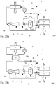
- the air conditioning circuit 1 can also operate in a fourth mode of operation illustrated in FIG. figure 10a .
- the refrigerant fluid passes successively into the compressor 3, the first heat exchanger 5, the ejector 7, springing through the second inlet 7b of the said ejector 7, passes through the second heat exchanger 13, the device 11, the phase separation device 9, passes through the bypass line A, passes through the third heat exchanger 17 before returning to the compressor 3.
- the air conditioning circuit 1 allows use in different modes of operation and also allows optimization of the COP.
Description
L'invention se rapporte au domaine des véhicules automobiles et plus particulièrement à un circuit de climatisation de véhicule automobile.The invention relates to the field of motor vehicles and more particularly to a motor vehicle air conditioning circuit.
Les véhicules automobiles actuels comportent de plus en plus souvent un circuit de climatisation. Généralement, dans un circuit de climatisation « classique », un fluide réfrigérant passe successivement dans un compresseur, un condenseur placé en contact avec un flux d'air extérieur au véhicule automobile pour libérer de la chaleur, un dispositif de détente et un évaporateur placé en contact avec un flux d'air intérieur du véhicule automobile pour le refroidir.Today's motor vehicles are increasingly equipped with an air conditioning system. Generally, in a "conventional" air conditioning circuit, a refrigerant fluid passes successively in a compressor, a condenser placed in contact with an air flow outside the motor vehicle to release heat, an expansion device and an evaporator placed in contact with an air flow inside the motor vehicle to cool it.
Les performances d'un circuit de climatisation sont généralement retranscrites par un coefficient de performance (COP pour « coefficient of perfomance » en anglais) qui correspond au quotient entre la chaleur restituée, au niveau du condenseur, et le travail fourni, notamment par le compresseur.The performance of an air conditioning circuit is generally retranscribed by a coefficient of performance (COP for "coefficient of perfomance" in English) which corresponds to the quotient between the heat returned, at the condenser, and the work provided, in particular by the compressor .
Afin d'améliorer le COP du circuit de climatisation il est connu d'utiliser comme dispositif de détente un éjecteur qui comporte :
- une première entrée de fluide réfrigérant en provenance du condenseur,
- une sortie de fluide réfrigérant en direction d'un dispositif de séparation de phases, et
- une deuxième entrée de fluide réfrigérant en provenance d'un évaporateur.
- a first refrigerant fluid inlet from the condenser,
- a coolant outlet to a phase separation device, and
- a second refrigerant fluid inlet from an evaporator.
Au niveau du dispositif de séparation de phases, la phase liquide du fluide réfrigérant est redirigée vers l'évaporateur et la phase gazeuse du fluide réfrigérant est quant à elle redirigée vers le compresseur.At the level of the phase separation device, the liquid phase of the refrigerant fluid is redirected towards the evaporator and the gas phase of the refrigerant fluid is in turn redirected to the compressor.
Cependant, lors de températures extérieures très basses, l'influence d'un éjecteur sur le COP peut être limitée voir s'inverser, c'est-à-dire que le COP peut diminuer et être inférieur à celui d'un circuit de climatisation « classique ».However, during very low external temperatures, the influence of an ejector on the COP can be limited or reversed, that is to say that the COP can decrease and be lower than that of an air conditioning circuit. "Classic".
Afin d'éviter cette diminution du COP, il est connu d'équiper le circuit de climatisation avec un échangeur de chaleur interne (IHX pour « internai heat exchanger » en anglais) qui permet un échange de chaleur entre le fluide réfrigérant en sortie du condenseur et le fluide réfrigérant en phase gazeuse en provenance du dispositif de séparation de phase.In order to avoid this reduction of the COP, it is known to equip the air conditioning circuit with an internal heat exchanger (IHX for "internai heat exchanger" in English) which allows a heat exchange between the refrigerant at the outlet of the condenser and the gas phase refrigerant from the phase separation device.
Cependant, l'utilisation d'un IHX diminue la température du fluide réfrigérant à l'entrée de l'éjecteur ce qui diminue l'efficacité dudit éjecteur et son impact sur le COP.However, the use of an IHX decreases the temperature of the refrigerant at the inlet of the ejector which decreases the effectiveness of said ejector and its impact on the COP.
Le document
Un des buts de la présente invention est donc de remédier au moins partiellement aux inconvénients de l'art antérieur et de proposer un circuit de climatisation amélioré.One of the aims of the present invention is therefore to at least partially overcome the disadvantages of the prior art and to provide an improved air conditioning circuit.
La présente invention concerne donc un circuit de climatisation pour véhicule automobile dans lequel circule un fluide réfrigérant et comportant dans le sens de circulation du fluide réfrigérant :
- ∘ un compresseur,
- ∘ un premier échangeur de chaleur destiné à être traversé par un flux d'air extérieur au véhicule automobile et disposé en aval du compresseur,
- ∘ un éjecteur disposé en aval du premier échangeur de chaleur, et comprenant :
- une première entrée de fluide réfrigérant, reliée audit premier échangeur de chaleur,
- une deuxième entrée de fluide réfrigérant, et
- une sortie de fluide réfrigérant,
- ∘ un dispositif de séparation de phases du fluide réfrigérant comportant :
- une entrée de fluide réfrigérant, reliée à la sortie de fluide réfrigérant de l'éjecteur,
- une première sortie de fluide réfrigérant en phase gazeuse, reliée au compresseur, et
- une deuxième sortie de fluide réfrigérant en phase liquide,
- ∘ un dispositif de détente disposé en aval de la deuxième sortie de fluide réfrigérant du dispositif de séparation de phases,
- ∘ un deuxième échangeur de chaleur destiné à être traversé par un flux d'air intérieur à destination de l'habitacle du véhicule automobile, ledit deuxième échangeur étant disposé en aval du dispositif de détente, entre ledit dispositif de détente et la deuxième entrée de fluide réfrigérant de l'éjecteur,
- ∘ un premier point de jonction disposé en aval de la sortie de fluide réfrigérant de l'éjecteur, entre ledit éjecteur et le dispositif de séparation de phases, et
- ∘ un deuxième point de jonction disposé en aval de la première sortie du dispositif de séparation de phases, entre ledit dispositif de séparation de phases et le compresseur,
- ∘ a compressor,
- A first heat exchanger intended to be traversed by a flow of air outside the motor vehicle and disposed downstream of the compressor,
- An ejector disposed downstream of the first heat exchanger, and comprising:
- a first refrigerant inlet connected to said first heat exchanger,
- a second refrigerant inlet, and
- a coolant outlet,
- A phase separation device for the refrigerant fluid comprising:
- a refrigerant inlet, connected to the coolant outlet of the ejector,
- a first coolant gas phase outlet connected to the compressor, and
- a second liquid phase refrigerant outlet,
- An expansion device disposed downstream of the second coolant outlet of the phase separation device,
- A second heat exchanger to be traversed by an interior air flow to the passenger compartment of the motor vehicle, said second exchanger being disposed downstream of the expansion device, between said expansion device and the second fluid inlet; refrigerant of the ejector,
- A first junction point disposed downstream of the ejector coolant outlet, between said ejector and the phase separation device, and
- A second junction point disposed downstream of the first output of the phase separation device, between said phase separation device and the compressor,
Selon un aspect de l'invention, le circuit de climatisation comporte un dispositif de gestion et de distribution du fluide réfrigérant en provenance de l'éjecteur vers la conduite de contournement et/ou le dispositif de séparation de phases.According to one aspect of the invention, the air conditioning circuit comprises a refrigerant management and distribution device from the ejector to the bypass line and / or the phase separation device.
Selon un autre aspect de l'invention, le dispositif de gestion et de distribution comporte une première vanne d'arrêt disposée entre le premier point de jonction et le dispositif de séparation de phases.According to another aspect of the invention, the management and distribution device comprises a first stop valve disposed between the first junction point and the phase separation device.
Selon un autre aspect de l'invention, le dispositif de gestion et de distribution comporte une deuxième vanne d'arrêt disposée sur la conduite de contournement.According to another aspect of the invention, the management and distribution device comprises a second stop valve disposed on the bypass line.
Selon un autre aspect de l'invention, le dispositif de gestion et de distribution comporte une vanne à ouverture variable disposée sur la conduite de contournement.According to another aspect of the invention, the management and distribution device comprises a variable opening valve disposed on the bypass line.
Selon un autre aspect de l'invention, le dispositif de gestion et de distribution comporte une vanne trois voies à débit variable disposée au niveau du premier point de jonction.According to another aspect of the invention, the management and distribution device comprises a variable-rate three-way valve disposed at the first junction point.
Selon un autre aspect de l'invention, le troisième échangeur de chaleur est destiné à être traversé par le flux d'air intérieur à destination de l'habitacle du véhicule automobile.According to another aspect of the invention, the third heat exchanger is intended to be traversed by the interior air flow to the passenger compartment of the motor vehicle.
Selon un autre aspect de l'invention, le troisième échangeur de chaleur est placé en amont du deuxième échangeur de chaleur dans le sens de circulation du flux d'air intérieur à destination de l'habitacle du véhicule automobile.According to another aspect of the invention, the third heat exchanger is placed upstream of the second heat exchanger in the direction of flow of the interior air flow to the passenger compartment of the motor vehicle.
Selon un autre aspect de l'invention, le circuit de climatisation comporte un échangeur de chaleur interne permettant un échange de chaleur entre le fluide réfrigérant en sortie du premier échangeur de chaleur et le fluide réfrigérant en sortie du dispositif de séparation de phases et/ou du troisième échangeur de chaleur.According to another aspect of the invention, the air conditioning circuit comprises an internal heat exchanger allowing a heat exchange between the refrigerant at the outlet of the first heat exchanger and the refrigerant at the outlet of the phase separation device and / or of the third heat exchanger.
Selon un autre aspect de l'invention, le circuit de climatisation est configuré pour fonctionner dans un premier mode de fonctionnement où le fluide réfrigérant passe successivement dans le compresseur, le premier échangeur de chaleur, l'éjecteur,
- ∘ une première portion de fluide réfrigérant passant par le dispositif de séparation de phases, et :
- ▪ la phase liquide du fluide réfrigérant passe ensuite dans le dispositif de détente, le deuxième échangeur de chaleur, le fluide réfrigérant revenant dans l'éjecteur,
- ▪ la phase gazeuse du fluide réfrigérant retourne vers le compresseur, et
- ∘ une deuxième portion du fluide réfrigérant passant par le troisième échangeur de chaleur de la conduite de contournement avant de retourner vers le compresseur.
- A first portion of refrigerant flowing through the phase separation device, and
- The liquid phase of the refrigerant then passes into the expansion device, the second heat exchanger, the refrigerant returning to the ejector,
- The gaseous phase of the refrigerant fluid returns to the compressor, and
- ∘ a second portion of the coolant passing through the third heat exchanger of the bypass pipe before returning to the compressor.
Selon un autre aspect de l'invention, le fluide réfrigérant en sortie du premier échangeur de chaleur passe dans l'échangeur de chaleur interne avant d'arriver à l'éjecteur, la phase gazeuse du fluide réfrigérant en sortie du dispositif de séparation de phases et le fluide réfrigérant en sortie du troisième échangeur de chaleur se mélange avant de passer dans l'échangeur de chaleur interne pour ensuite retourner vers le compresseur.According to another aspect of the invention, the refrigerant fluid at the outlet of the first heat exchanger passes into the internal heat exchanger before reaching the ejector, the gaseous phase of the refrigerant at the outlet of the phase separation device and the coolant at the outlet of the third heat exchanger mixes before passing into the internal heat exchanger and then back to the compressor.
Selon un autre aspect de l'invention, le circuit de climatisation est configuré pour fonctionner dans un deuxième mode de fonctionnement où le fluide réfrigérant passe successivement dans le compresseur, le premier échangeur de chaleur, l'éjecteur, le troisième échangeur de chaleur de la conduite de contournement avant de retourner vers le compresseur.According to another aspect of the invention, the air conditioning circuit is configured to operate in a second mode of operation where the refrigerant passes successively in the compressor, the first heat exchanger, the ejector, the third heat exchanger of the bypass before returning to the compressor.
Selon un autre aspect de l'invention, le fluide réfrigérant en sortie du premier échangeur de chaleur passe dans l'échangeur de chaleur interne avant d'arriver à l'éjecteur et le fluide réfrigérant en sortie du troisième échangeur de chaleur passe dans l'échangeur de chaleur interne avant de retourner vers le compresseur.According to another aspect of the invention, the refrigerant at the outlet of the first heat exchanger passes into the internal heat exchanger before reaching the ejector and the refrigerant at the outlet of the third heat exchanger passes through the heat exchanger. internal heat exchanger before returning to the compressor.
Selon un autre aspect de l'invention, le circuit de climatisation est configuré pour fonctionner dans un troisième mode de fonctionnement où le fluide réfrigérant passe successivement dans le compresseur, le premier échangeur de chaleur, l'éjecteur, le dispositif de séparation de phases, et :
- ∘ la phase liquide du fluide réfrigérant passe ensuite dans le dispositif de détente, le deuxième échangeur de chaleur, le fluide réfrigérant revenant dans l'éjecteur,
- ∘ la phase gazeuse du fluide réfrigérant retourne vers le compresseur.
- ∘ the liquid phase of the refrigerant then passes into the expansion device, the second heat exchanger, the refrigerant returning to the ejector,
- ∘ the gas phase of the coolant returns to the compressor.
Selon un autre aspect de l'invention, le fluide réfrigérant en sortie du premier échangeur de chaleur passe dans l'échangeur de chaleur interne avant d'arriver à l'éjecteur et la phase gazeuse du fluide réfrigérant en sortie du dispositif de séparation de phases passe dans l'échangeur de chaleur interne avant de retourner vers le compresseur.According to another aspect of the invention, the refrigerant at the outlet of the first heat exchanger passes into the internal heat exchanger before reaching the ejector and the gaseous phase of the refrigerant at the outlet of the phase separation device passes through the internal heat exchanger before returning to the compressor.
D'autres caractéristiques et avantages de l'invention apparaîtront plus clairement à la lecture de la description suivante, donnée à titre d'exemple illustratif et non limitatif, et des dessins annexés parmi lesquels :
- la
figure 1 montre une représentation schématique d'un circuit de climatisation selon un premier mode de réalisation, - la
figure 2 montre une représentation schématique d'un circuit de climatisation selon un deuxième mode de réalisation, - la
figure 3a montre une représentation schématique du circuit de climatisation de lafigure 1 selon un premier mode de fonctionnement, - la
figure 3b montre un diagramme pression / enthalpie du fluide réfrigérant selon le premier mode de fonctionnement de lafigure 3a , - la
figure 4a montre une représentation schématique du circuit de climatisation de lafigure 2 selon une variante du premier mode de fonctionnement, - la
figure 4b montre un diagramme pression / enthalpie du fluide réfrigérant selon la variante du premier mode de fonctionnement de lafigure 4a , - les
figures 5a à 5c montrent des représentations schématiques de dispositifs de gestion et de distribution selon différents modes de réalisation, - la
figure 6a montre une représentation schématique du circuit de climatisation de lafigure 1 selon un deuxième mode de fonctionnement, - la
figure 6b montre un diagramme pression / enthalpie du fluide réfrigérant selon le deuxième mode de fonctionnement de lafigure 6a . - la
figure 7a montre une représentation schématique du circuit de climatisation de lafigure 2 selon une variante du deuxième mode de fonctionnement, - la
figure 7b montre un diagramme pression / enthalpie du fluide réfrigérant selon la variante du deuxième mode de fonctionnement de lafigure 7a . - la
figure 8a montre une représentation schématique du circuit de climatisation de lafigure 1 selon un troisième mode de fonctionnement, - la
figure 8b montre un diagramme pression / enthalpie du fluide réfrigérant selon le troisième mode de fonctionnement de lafigure 8a . - la
figure 9a montre une représentation schématique du circuit de climatisation de lafigure 2 selon une variante du troisième mode de fonctionnement, - la
figure 9b montre un diagramme pression / enthalpie du fluide réfrigérant selon la variante du troisième mode de fonctionnement de lafigure 9a , - la
figure 10a montre une représentation schématique du circuit de climatisation de lafigure 1 selon un quatrième mode de fonctionnement, - la
figure 10b montre une représentation schématique du circuit de climatisation de lafigure 2 selon le quatrième mode de fonctionnement.
- the
figure 1 shows a schematic representation of an air conditioning circuit according to a first embodiment, - the
figure 2 shows a schematic representation of an air conditioning circuit according to a second embodiment, - the
figure 3a shows a schematic representation of the air conditioning circuit of thefigure 1 according to a first mode of operation, - the
figure 3b shows a pressure / enthalpy diagram of the refrigerant according to the first operating mode of thefigure 3a , - the
figure 4a shows a schematic representation of the air conditioning circuit of thefigure 2 according to a variant of the first mode of operation, - the
figure 4b shows a pressure / enthalpy diagram of the coolant according to the variant of the first operating mode of thefigure 4a , - the
Figures 5a to 5c show schematic representations of management and distribution devices according to different embodiments, - the
figure 6a shows a schematic representation of the air conditioning circuit of thefigure 1 according to a second mode of operation, - the
figure 6b shows a pressure / enthalpy diagram of the refrigerant according to the second mode of operation of thefigure 6a . - the
figure 7a shows a schematic representation of the air conditioning circuit of thefigure 2 according to a variant of the second mode of operation, - the
figure 7b shows a pressure / enthalpy diagram of the refrigerant according to the variant of the second operating mode of thefigure 7a . - the
figure 8a shows a schematic representation of the air conditioning circuit of thefigure 1 according to a third mode of operation, - the
figure 8b shows a pressure / enthalpy diagram of the refrigerant according to the third mode of operation of thefigure 8a . - the
figure 9a shows a schematic representation of the air conditioning circuit of thefigure 2 according to a variant of the third mode of operation, - the
figure 9b shows a pressure / enthalpy diagram of the coolant according to the variant of the third mode of operation of thefigure 9a , - the
figure 10a shows a schematic representation of the air conditioning circuit of thefigure 1 according to a fourth mode of operation, - the
figure 10b shows a schematic representation of the air conditioning circuit of thefigure 2 according to the fourth mode of operation.
Sur les différentes figures, les éléments identiques portent les mêmes numéros de référence.In the different figures, the identical elements bear the same reference numbers.
Les réalisations suivantes sont des exemples. Bien que la description se réfère à un ou plusieurs modes de réalisation, ceci ne signifie pas nécessairement que chaque référence concerne le même mode de réalisation, ou que les caractéristiques s'appliquent seulement à un seul mode de réalisation. De simples caractéristiques de différents modes de réalisation peuvent également être combinées et/ou interchangées pour fournir d'autres réalisations.The following achievements are examples. Although the description refers to one or more embodiments, this does not necessarily mean that each reference relates to the same embodiment, or that the features apply only to a single embodiment. Simple features of different embodiments may also be combined and / or interchanged to provide other embodiments.
Dans la présente description, on peut indexer certains éléments ou paramètres, comme par exemple premier élément ou deuxième élément ainsi que premier paramètre et second paramètre ou encore premier critère et deuxième critère etc. Dans ce cas, il s'agit d'un simple indexage pour différencier et dénommer des éléments ou paramètres ou critères proches mais non identiques. Cette indexation n'implique pas une priorité d'un élément, paramètre ou critère par rapport à un autre et on peut aisément interchanger de telles dénominations sans sortir du cadre de la présente description. Cette indexation n'implique pas non plus un ordre dans le temps par exemple pour apprécier tel ou tel critère.In the present description, it is possible to index certain elements or parameters, for example first element or second element as well as first parameter and second parameter or else first criterion and second criterion, etc. In this case, it is a simple indexing to differentiate and name elements or parameters or criteria close but not identical. This indexing does not imply a priority of one element, parameter or criterion with respect to another, and it is easy to interchange such denominations without departing from the scope of the present description. This indexing does not imply either an order in time for example to appreciate this or that criterion.
Dans la présente description, on entend par « placé en amont » qu'un élément est placé avant un autre par rapport au sens de circulation d'un fluide. A contrario, on entend par « placé en aval » qu'un élément est placé après un autre par rapport au sens de circulation du fluide.In the present description, the term "placed upstream" means that one element is placed before another relative to the direction of flow of a fluid. Conversely, "downstream" means that one element is placed after another relative to the direction of fluid flow.
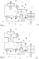
La
∘ un compresseur 3,- ∘ un premier échangeur de chaleur 5 destiné à être traversé par un flux d'air extérieur 100 au véhicule automobile et disposé en aval du compresseur 3,
∘ un éjecteur 7 disposé en aval du premier échangeur de chaleur 5, et comprenant :- une première entrée 7a de fluide réfrigérant, reliée audit premier échangeur de chaleur 5,
- une deuxième entrée 7b de fluide réfrigérant, et
une sortie 7c de fluide réfrigérant,
- ∘ un dispositif de séparation de phases 9 du fluide réfrigérant comportant :
- une entrée de fluide réfrigérant 9a, reliée à la
sortie 7c de fluide réfrigérant de l'éjecteur 7, une première sortie 9b de fluide réfrigérant en phase gazeuse, reliée au compresseur 3, et- une deuxième sortie 9c de fluide réfrigérant en phase liquide,
- une entrée de fluide réfrigérant 9a, reliée à la
- ∘ un dispositif de détente 11 disposé en aval de la deuxième sortie 9c de fluide réfrigérant du dispositif de séparation de phases 9,
- ∘ un deuxième échangeur de chaleur 13 destiné à être traversé par un flux d'air intérieur 200 à destination de l'habitacle du véhicule automobile, ledit deuxième échangeur 13 étant disposé en aval du dispositif de détente 11, entre ledit dispositif de détente 11 et la deuxième entrée 7b de fluide réfrigérant de l'éjecteur 7.
- ∘ a
compressor 3, - A first heat exchanger intended to be traversed by an
external air flow 100 to the motor vehicle and disposed downstream of thecompressor 3, - An
ejector 7 disposed downstream of thefirst heat exchanger 5, and comprising:- a
first coolant inlet 7a, connected to saidfirst heat exchanger 5, - a
second coolant inlet 7b, and - an
outlet 7c of refrigerant,
- a
- A
phase separation device 9 for the refrigerant fluid comprising:- a
refrigerant inlet 9a, connected to theoutlet 7c of the refrigerant of theejector 7, - a
first outlet 9b of refrigerant in the gas phase, connected to thecompressor 3, and - a
second outlet 9c of coolant in the liquid phase,
- a
- An
expansion device 11 arranged downstream of thesecond coolant outlet 9c of thephase separation device 9, - A
second heat exchanger 13 to be traversed by aninterior air flow 200 to the passenger compartment of the motor vehicle, saidsecond exchanger 13 being disposed downstream of theexpansion device 11, between saidexpansion device 11 and thesecond coolant inlet 7b of theejector 7.
Le fluide réfrigérant peut notamment être du dioxyde de carbone connu dans le domaine des circuit de climatisation sous le nom R744.The refrigerant may in particular be carbon dioxide known in the field of air conditioning circuit under the name R744.
Le circuit de climatisation 1 comporte en outre une conduite de contournement A du dispositif de séparation de phases 9 et reliant :
- ∘ un premier point de jonction 15a disposé en aval de la
sortie 7c de fluide réfrigérant de l'éjecteur 7, entre ledit éjecteur 7 et le dispositif de séparation de phases 9, et - ∘ un deuxième point de jonction 15b disposé en aval de la première
sortie 9b du dispositif de séparation de phases 9, entre ledit dispositif de séparation de phases 9 et le compresseur 3.
- A
first junction point 15a disposed downstream of thecoolant outlet 7c of theejector 7, between saidejector 7 and thephase separation device 9, and - A
second junction point 15b disposed downstream of thefirst output 9b of thephase separation device 9 between saidphase separation device 9 and thecompressor 3.
La conduite de contournement A comporte également un troisième échangeur de chaleur 17.The bypass line A also comprises a
Comme le montre la
La présence de la conduite de contournement A et du troisième échangeur de chaleur 17 permet au circuit de climatisation 1 de fonctionner selon un premier mode de fonctionnement illustré à la
Dans ce premier mode de fonctionnement de la
- ∘ une première portion de fluide réfrigérant passe par le dispositif de séparation de phases 9, et :
- ▪ la phase liquide du fluide réfrigérant passe ensuite dans le dispositif de détente 11, le deuxième échangeur de chaleur 13, le fluide réfrigérant revenant dans l'éjecteur 7,
- ▪ la phase gazeuse du fluide réfrigérant retourne vers le compresseur 3, et
- ∘ une deuxième portion du fluide réfrigérant passe par le troisième échangeur de chaleur 17 de la conduite de contournement A avant de retourner vers le compresseur 3, via le deuxième point de jonction 15b.
- A first portion of refrigerant fluid passes through the
phase separation device 9, and- The liquid phase of the refrigerant then passes into the
expansion device 11, thesecond heat exchanger 13, the refrigerant returning to theejector 7, - The gaseous phase of the refrigerant fluid returns to the
compressor 3, and
- The liquid phase of the refrigerant then passes into the
- A second portion of the coolant passes through the
third heat exchanger 17 of the bypass line A before returning to thecompressor 3, via thesecond junction point 15b.
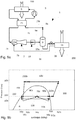
Les variations de pression et d'enthalpie que subit le fluide réfrigérant lors de ce premier mode de fonctionnement, sont illustrées sur le diagramme pression / enthalpie de la
Le fluide réfrigérant à l'entrée du compresseur 3 est en phase gazeuse à une pression p1a et a une enthalpie h1a. Le fluide réfrigérant subit une compression, illustrée par la flèche 300, en passant dans le compresseur 3 et passe à une pression p2a pour une enthalpie h2a.The refrigerant at the inlet of the
Le fluide réfrigérant traverse le premier échangeur de chaleur 5 et subit une perte d'enthalpie, illustrée par la flèche 500, du fait de la dissipation de chaleur dans le flux d'air extérieur 100 et de son passage en phase liquide. Le fluide réfrigérant passe alors d'une enthalpie h2a à une enthalpie h3a, tout en restant à une pression constante p2a.The refrigerant passes through the
Le fluide réfrigérant passe ensuite dans la première entrée 7a de l'éjecteur 7. Le fluide réfrigérant subit une perte de pression, illustrée par la flèche 70a et croise la courbe de saturation B, ce qui le fait passer dans un état de mélange liquide plus gaz. Le fluide réfrigérant subit ensuite une recompression dans l'éjecteur 7, pour atteindre la sortie 7c dudit l'éjecteur 7, illustrée par le point 70c. A la sortie 7c de l'éjecteur 7, le fluide réfrigérant est à la pression p1a et a une enthalpie h4a supérieure à l'enthalpie h3a précédente.The refrigerant then passes into the
Une partie du fluide réfrigérant passe ensuite dans le dispositif de séparation de phases 9, alors que l'autre partie du fluide réfrigérant passe dans la conduite de contournement A.Part of the refrigerant then passes into the
Au niveau du dispositif de séparation de phases 9, la phase liquide du fluide réfrigérant est séparée de la phase gazeuse. De ce fait, l'enthalpie du fluide réfrigérant en phase liquide à la deuxième sortie 9c du dispositif de séparation de phases 9, diminue pour rejoindre la courbe de saturation B et atteindre une valeur h5a. Cette diminution est illustrée par la flèche 90c. Le fluide réfrigérant passe ensuite dans le dispositif de détente 11 où il subit une détente, illustrée par la flèche 110, passant de la pression p1a à la pression p3a. Le fluide réfrigérant traverse ensuite le deuxième échangeur de chaleur 13 où il subit une évaporation, illustrée par la flèche 130. Le fluide réfrigérant lors de sa traversée du deuxième échangeur de chaleur 13 absorbe de l'énergie calorifique du flux d'air intérieur 200 et passe de l'enthalpie h5a à l'enthalpie h6a. Le fluide réfrigérant repasse ensuite dans l'éjecteur 7 via sa deuxième entrée 7b, il subit de nouveau une perte de pression puis une recompression dans l'éjecteur 7 pour rejoindre le point 70c, c'est à dire à une pression p1a et une enthalpie h4a, comme le montre la flèche 70b.At the level of the
Toujours au niveau du dispositif de séparation de phases 9, la phase gazeuse du fluide réfrigérant est quant à elle redirigée vers le compresseur 3. Du fait de la séparation de phases, le fluide réfrigérant en phase gazeuse à la première sortie 9b du dispositif de séparation de phases 9, tend à atteindre la courbe de saturation B en gagnant de l'enthalpie, comme le montre la flèche 90b. Avant d'atteindre le compresseur 3 le fluide réfrigérant issue de la première sortie 9a du dispositif de séparation de phases 9 se mélange au niveau du deuxième point de jonction 15b avec le fluide réfrigérant en provenance de la conduite de contournement A.Still at the level of the
Au sein de la conduite de contournement A, le fluide réfrigérant passe au travers du troisième échangeur de chaleur 17 où il gagne de l'enthalpie comme illustré par la flèche 170. Ce mélange entre le fluide réfrigérant en phase gazeuse issu du dispositif de séparation de phases 9 et le fluide réfrigérant issue de la conduite de contournement A, permet d'atteindre l'enthalpie h1a du fluide réfrigérant qui dépasse la courbe de saturation B. Le fluide réfrigérant est donc en état de gaz surchauffé à l'enthalpie h1a et est à la pression p1a avant d'entrer dans le compresseur 3.In the bypass line A, the refrigerant passes through the
Le coefficient de performance (COP pour « coefficient of perfomance ») est amélioré par rapport à un circuit de climatisation « classique » de deux façons.The performance coefficient (COP for "coefficient of perfomance") is improved over a "conventional" air conditioning circuit in two ways.
Premièrement, le COP est amélioré par l'action de l'éjecteur 7 qui permet au fluide réfrigérant, en entrée du compresseur 3, d'avoir une pression p1a supérieure à la pression p3a où l'échange de chaleur entre le flux d'air intérieur 200 et le fluide réfrigérant a lieu au niveau du deuxième échangeur de chaleur 13. Moins de puissance au niveau du compresseur 3 est donc nécessaire pour atteindre la pression p2a.First, the COP is improved by the action of the
Deuxièmement, le COP est amélioré du fait de la présence du troisième échangeur de chaleur 17 qui permet une surchauffe du fluide réfrigérant avant son entrée dans le compresseur 3 et donc un gain d'enthalpie.Second, the COP is improved because of the presence of the
Selon une variante, le premier mode de fonctionnement peut fonctionner lorsque le circuit de climatisation 1 comporte un IHX 21, comme cela est illustré à la
- avant d'arriver dans l'éjecteur 7 au niveau de la première entrée 7a, le fluide réfrigérant passe
par l'IHX 21, et - avant d'arriver dans le compresseur 3, le mélange de fluide réfrigérant issue de la première
sortie 9b du dispositif de séparation de phases 9 et du fluide réfrigérant en provenance de la conduite de contournement A passe égalementpar l'IHX 21.
- before reaching the
ejector 7 at thefirst inlet 7a, the coolant passes through theIHX 21, and - before arriving in the
compressor 3, the refrigerant mixture from thefirst outlet 9b of thephase separation device 9 and the refrigerant from the bypass line A also passes through theIHX 21.
L'influence de l'IHX 21 est visible sur le diagramme pression /enthalpie de la
Néanmoins, plus l'enthalpie h3'a du fluide avant d'arriver dans l'éjecteur 7 au niveau de la première entrée 7a est faible, par exemple du fait de températures extérieures basses, moins l'efficacité de l'éjecteur 7 sur le COP est bonne. En effet, cela limite la recompression du fluide réfrigérant au niveau de l'éjecteur 7 qui permet au fluide réfrigérant de passer de la pression p3a au niveau du deuxième échangeur de chaleur 17 à la pression p1a avant son entrée dans le compresseur 3. Il faudrait alors augmenter la puissance du compresseur 3, et donc diminuer le COP, pour compenser cette diminution de la différence de pression entre p3a et p1a. Par exemple, pour des températures extérieures basses, le COP d'un circuit de climatisation 1 avec éjecteur 7 et IHX 21 peut être inférieur à un circuit de climatisation « classique » comprenant un IHX 21.Nevertheless, the greater the enthalpy h3 'has fluid before arriving in the
Le fait que le circuit de climatisation 1 comporte une boucle de contournement A comprenant le troisième échangeur de chaleur 17 permet de limiter cet effet négatif de l'IHX 21 sur l'efficacité de l'éjecteur 7. En effet, le troisième échangeur de chaleur 17 surchauffe le fluide réfrigérant qui est ainsi à une enthalpie h1a avant d'entrer dans l'IHX 21. Le fait que le fluide réfrigérant en provenance du dispositif de séparation de phase 9 et de la boucle de contournement A soit plus chaud, diminue l'efficacité de l'IHX 21 et donc l'enthalpie h3'a du fluide réfrigérant avant d'arriver dans l'éjecteur 7 au niveau de la première entrée 7a, sera moins faible et donc permettra à l'éjecteur 7 d'être efficace sur le COP du circuit de climatisation 1.The fact that the
Le troisième échangeur de chaleur 17 peut par exemple être, à l'instar du deuxième échangeur de chaleur 13, destiné à être traversé par un flux d'air intérieur 200 à destination de l'habitacle du véhicule automobile. Dans ce cas de figure, ledit troisième échangeur de chaleur 17 est de préférence placé en amont du deuxième échangeur de chaleur 13, dans le sens de circulation du flux d'air intérieur 200 à destination de l'habitacle du véhicule automobile. En effet, cela permet au troisième échangeur de chaleur 17 d'être alimenté par un flux d'air intérieur 200 chaud et d'y puiser de l'énergie calorifique avant que ledit flux d'air intérieur 200 ne traverse le deuxième échangeur de chaleur 13. Cela permet également une augmentation de la surface d'échange entre le fluide réfrigérant et le flux d'air intérieur 200 et ainsi améliore les échanges de chaleur entre ledit fluide réfrigérant et ledit flux d'air intérieur 200.The
Il est cependant tout à fait possible d'imaginer une position différente du troisième échangeur de chaleur 17. Ce dernier peut par exemple être un échangeur de chaleur branché sur autre circuit d'échange ou de régulation thermique du véhicule avec lequel il peut échanger de l'énergie calorifique.However, it is quite possible to imagine a different position of the
Le circuit de climatisation 1 peut également comporter un dispositif de gestion et de distribution 19 du fluide réfrigérant en provenance de l'éjecteur 7 vers la conduite de contournement A et/ou le dispositif de séparation de phases 9. Ce dispositif de gestion et de distribution 19 permet le contrôle de la circulation du fluide réfrigérant.The
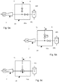
Comme illustré sur les
Selon un premier mode de réalisation du dispositif de gestion et de distribution 19 illustré à la
Selon un deuxième mode de réalisation du dispositif de gestion et de distribution 19 illustré à la
Comme illustré sur la
La présence du dispositif de gestion et de distribution 19 permet au circuit de climatisation 1 d'adopter différents modes de fonctionnement. En effet, il est possible de contrôler vers où le fluide réfrigérant est dirigé. Il est même possible, selon les besoins, de faire varier la quantité de fluide réfrigérant envoyée vers le deuxième échangeur de chaleur 13 ou dans la conduite de contournement A, lorsque que le dispositif de gestion et de distribution 19 comporte une vanne à ouverture variable 195 ou une vanne trois voies 197 à débit variable.The presence of the management and
Le circuit de climatisation 1 peut ainsi fonctionner selon un deuxième mode de fonctionnement illustré à la
Dans ce deuxième mode de fonctionnement, le fluide réfrigérant passe successivement dans le compresseur 3, le premier échangeur de chaleur 5, l'éjecteur 7 et dans le troisième échangeur de chaleur 17 de la conduite de contournement A avant de retourner vers le compresseur 3.In this second mode of operation, the coolant passes successively in the
Les variations de pression et d'enthalpie que subit le fluide réfrigérant lors de ce deuxième mode de fonctionnement, sont illustrées sur le diagramme pression / enthalpie de la
Le fluide réfrigérant à l'entrée du compresseur 3 est en phase gazeuse à une pression p1b et a une enthalpie h1b. Le fluide réfrigérant subit une compression, illustrée par la flèche 300, en passant dans le compresseur 3 et passe à une pression p2b et à une enthalpie h2b.The refrigerant at the inlet of the
Le fluide réfrigérant traverse le premier échangeur de chaleur 5 et subit une perte d'enthalpie, illustrée par la flèche 500, du fait de la dissipation de chaleur dans le flux d'air extérieur 100 et de son passage en phase liquide. Le fluide réfrigérant passe alors d'une enthalpie h2b à une enthalpie h3b, tout en restant à une pression constante p2b.The refrigerant passes through the
Le fluide réfrigérant passe ensuite dans la première entrée 7a de l'éjecteur 7. Le fluide réfrigérant subit une perte de pression, illustrée par la flèche 700 et croise la courbe de saturation B, ce qui le fait passer dans un état de mélange liquide plus gaz. A la sortie 7c de l'éjecteur 7, le fluide réfrigérant est à la pression p1b et a une enthalpie h3b.The refrigerant then passes into the
Le fluide réfrigérant passe ensuite dans le dispositif de gestion et de distribution 19 et est redirigé dans la conduite de contournement A.The refrigerant then passes into the management and
Au sein de la conduite de contournement A, le fluide réfrigérant passe au travers du troisième échangeur de chaleur 17 où il gagne de l'enthalpie comme illustré par la flèche 170. Le fluide réfrigérant passe alors de l'enthalpie h3b à l'enthalpie h1b à la pression p1b, avant de rentrer de nouveau dans le compresseur 3.In the bypass line A, the refrigerant passes through the
Selon une variante, le deuxième mode de fonctionnement peut fonctionner lorsque le circuit de climatisation 1 comporte un IHX 21 comme cela est illustré à la
- avant d'arriver dans l'éjecteur 7 au niveau de la première entrée 7a, le fluide réfrigérant passe
par l'IHX 21, et - avant d'arriver dans le compresseur 3, le fluide réfrigérant en provenance de la conduite de contournement A passe également
par l'IHX 21.
- before reaching the
ejector 7 at thefirst inlet 7a, the coolant passes through theIHX 21, and - before reaching the
compressor 3, the refrigerant from the bypass line A also passes through theIHX 21.
L'influence de l'IHX 21 est visible sur le diagramme pression /enthalpie de la
Ce deuxième mode de fonctionnement et sa variante sont des équivalents à un fonctionnement « classique » d'un circuit de climatisation « classique » avec et sans IHX 21. L'éjecteur 7 n'amorce pas et a ici un rôle de détendeur simple. Ce deuxième mode de réalisation est de préférence utilisé pour des températures d'air extérieur en entrée du premier échangeur de chaleur 5 inférieures à 15° C et pour des fluides réfrigérant à faible charge thermique.This second mode of operation and its variant are equivalent to a "classic" operation of a "conventional" air conditioning circuit with and without
Le circuit de climatisation 1 peut également fonctionner selon un troisième mode de fonctionnement illustré à la
Dans ce troisième mode de fonctionnement, le fluide réfrigérant passe successivement dans le compresseur 3, le premier échangeur de chaleur 5, l'éjecteur 7, le dispositif de séparation de phases 9, et :
- ∘ la phase liquide du fluide réfrigérant passe ensuite dans le dispositif de détente 11, le deuxième échangeur de chaleur 13, le fluide réfrigérant revenant dans l'éjecteur 7,
- ∘ la phase gazeuse du fluide réfrigérant retourne vers le compresseur 3.
- ∘ the liquid phase of the refrigerant then passes into the
expansion device 11, thesecond heat exchanger 13, the refrigerant returning to theejector 7, - ∘ the gaseous phase of the coolant returns to the
compressor 3.
Les variations de pression et d'enthalpie que subit le fluide réfrigérant lors de ce troisième mode de fonctionnement, sont illustrées sur le diagramme pression / enthalpie de la
Le fluide réfrigérant à l'entrée du compresseur 3 est en phase gazeuse à une pression p1c et a une enthalpie h1c. Le fluide réfrigérant subit une compression, illustrée par la flèche 300, en passant dans le compresseur 3 et passe à une pression p2c et à une enthalpie h2c.The refrigerant at the inlet of the
Le fluide réfrigérant traverse le premier échangeur de chaleur 5 et subit une perte d'enthalpie, illustrée par la flèche 500, du fait de la dissipation de chaleur dans le flux d'air extérieur 100 et de son passage en phase liquide. Le fluide réfrigérant passe alors d'une enthalpie h2c à une enthalpie h3c, tout en restant à une pression constante p2c.The refrigerant passes through the
Le fluide réfrigérant passe ensuite dans la première entrée 7a de l'éjecteur 7. Le fluide réfrigérant subit une perte de pression, illustrée par la flèche 70a, et croise la courbe de saturation B, ce qui le fait passer dans un état de mélange liquide plus gaz. Le fluide réfrigérant subit ensuite une recompression dans l'éjecteur 7 pour atteindre la sortie 7c dudit l'éjecteur 7, illustrée par le point 70c. A la sortie 7c de l'éjecteur 7, le fluide réfrigérant est la pression p1c et a une enthalpie h4c supérieure à l'enthalpie h3a précédente.The refrigerant then passes into the
Le fluide réfrigérant passe ensuite dans le dispositif de séparation de phases 9. Au niveau du dispositif de séparation de phases 9, la phase liquide du fluide réfrigérant est séparée de la phase gazeuse. De ce fait, l'enthalpie du fluide réfrigérant en phase liquide à la deuxième sortie 9c du dispositif de séparation de phases 9, diminue pour rejoindre la courbe de saturation B et atteindre une valeur h5c. Cette diminution est illustrée par la flèche 90c. Le fluide réfrigérant passe ensuite dans le dispositif de détente 11 où il subit une détente, illustrée par la flèche 110, passant de la pression p1c à la pression p3c. Le fluide réfrigérant traverse ensuite le deuxième échangeur de chaleur 13 où il subit une évaporation, illustrée par la flèche 130. Le fluide réfrigérant lors de sa traversée du deuxième échangeur de chaleur 13 absorbe de l'énergie calorifique du flux d'air intérieur 200 et passe de l'enthalpie h5c à l'enthalpie h6c. Le fluide réfrigérant repasse ensuite dans l'éjecteur 7 via sa deuxième entrée 7b, il subit de nouveau une perte de pression puis une recompression dans l'éjecteur 7 pour rejoindre le point 70c, c'est à dire à une pression p1c et une enthalpie h4c, comme le montre la flèche 70b.The refrigerant then flows into the
Toujours au niveau du dispositif de séparation de phases 9, la phase gazeuse du fluide réfrigérant est quant à elle redirigée vers le compresseur 3. Du fait de la séparation de phase, le fluide réfrigérant en phase gazeuse à la première sortie 9b du dispositif de séparation de phases 9, tend à atteindre la courbe de saturation B en gagnant de l'enthalpie, comme montré par la flèche 90b, et atteint l'enthalpie h1c à la pression p1c.Still at the level of the
Le COP est amélioré par rapport à un circuit de climatisation « classique » par l'action de l'éjecteur 7 qui permet au fluide réfrigérant en entrée dudit compresseur 3 d'avoir une pression p1c supérieure à la pression p3c où l'échange de chaleur, entre le flux d'air intérieur 200 et le fluide réfrigérant, a lieu au niveau du deuxième échangeur de chaleur 13. Moins de puissance au niveau du compresseur 3 est donc nécessaire pour atteindre la pression p2c.The COP is improved compared to a "conventional" air conditioning circuit by the action of the
Ce troisième mode de fonctionnement est de préférence utilisé pour des températures d'air extérieur en entrée du premier échangeur de chaleur 5 supérieures à 60° C et notamment lorsque le fluide réfrigérant est du R744. En effet pour ce telles températures, l'éjecteur 7 fera subir au fluide réfrigérant une recompression importante et donc la pression au sein du dispositif de séparation de phases 9 sera trop importante et pourrait endommager le circuit.This third mode of operation is preferably used for outside air temperatures at the inlet of the
Selon une variante, le troisième mode de fonctionnement peut fonctionner lorsque le circuit de climatisation 1 comporte un IHX 21 comme cela est illustré à la
- avant d'arriver dans l'éjecteur 7 au niveau de la première entrée 7a, le fluide réfrigérant passe
par l'IHX 21, et - avant d'arriver dans le compresseur 3, le mélange de fluide réfrigérant issue de la première
sortie 9b du dispositif de séparation dephase 9 passe égalementpar l'IHX 21.
- before reaching the
ejector 7 at thefirst inlet 7a, the coolant passes through theIHX 21, and - before reaching the
compressor 3, the coolant mixture from thefirst outlet 9b of thephase separation device 9 also passes through theIHX 21.
L'influence de l'IHX 21 est visible sur le diagramme pression /enthalpie de la
Le circuit de climatisation 1 peut également fonctionner dans un quatrième mode de fonctionnement illustré à la
Dans ce quatrième mode de fonctionnement, le fluide réfrigérant passe successivement dans le compresseur 3, le premier échangeur de chaleur 5, l'éjecteur 7, ressort par la deuxième entrée 7b dudit éjecteur 7, passe par le deuxième échangeur de chaleur 13, le dispositif de détente 11, le dispositif de séparation de phase 9, passe dans la conduite de contournement A, traverse le troisième échangeur de chaleur 17 avant de retourner au compresseur 3.In this fourth mode of operation, the refrigerant fluid passes successively into the
Selon une variante, le quatrième mode de fonctionnement peut fonctionner lorsque le circuit de climatisation 1 comporte un IHX 21 comme cela est illustré à la
- avant d'arriver dans l'éjecteur 7 au niveau de la première entrée 7a, le fluide réfrigérant passe
par l'IHX 21, et - avant d'arriver dans le compresseur 3, le mélange de fluide réfrigérant en provenance du troisième échangeur de chaleur 17 passe
également par l'IHX 21.
- before reaching the
ejector 7 at thefirst inlet 7a, the coolant passes through theIHX 21, and - before arriving in the
compressor 3, the coolant mixture from thethird heat exchanger 17 also passes through theIHX 21.
Ainsi, on voit bien que de part son architecture, le circuit de climatisation 1 selon l'invention permet une utilisation selon différents modes de fonctionnement et permet également une optimisation du COP.Thus, it is clear that its architecture, the
Claims (15)
- Air conditioning circuit (1) for a motor vehicle, through which there circulates a refrigerant and which comprises, in the direction in which the refrigerant circulates:∘ a compressor (3),∘ a first heat exchanger (5) intended to have passing through it a flow (100) of air external to the motor vehicle and positioned downstream of the compressor (3),∘ an ejector (7) positioned downstream of the first heat exchanger (5) and comprising:• a first refrigerant inlet (7a), connected to said first heat exchanger (5),• a second refrigerant inlet (7b), and• a refrigerant outlet (7c),∘ a refrigerant phase-separation device (9) comprising:• a refrigerant inlet (9a) connected to the refrigerant outlet (7c) of the ejector (7),• a first refrigerant outlet (9b) for refrigerant in the gaseous phase, which is connected to the compressor (3), and• a second refrigerant outlet (9c) for refrigerant in the liquid phase,∘ an expansion device (11) positioned downstream of the second refrigerant outlet (9c) of the phase-separation device (9),∘ a second heat exchanger (13) intended to have passing through it a flow (200) of internal air intended for the motor vehicle interior, said second exchanger (13) being positioned downstream of the expansion device (11), between said expansion device (11) and the second refrigerant inlet (7b) of the ejector (7),characterized in that the air conditioning circuit (1) further comprises a bypass line (A) bypassing the phase-separation device (9) and connecting:∘ a first junction point (15a) positioned downstream of the refrigerant outlet (7c) of the ejector (7), between said ejector (7) and the phase-separation device (9), and∘ a second junction point (15b) positioned downstream of the first outlet (9b) of the phase-separation device (9), between said phase-separation device (9) and the compressor (3), said bypass line (A) comprising a third heat exchanger (17).
- Air conditioning circuit (1) according to the preceding claim, characterized in that the air conditioning circuit (1) comprises a management and distribution device (19) for the refrigerant coming from the ejector (7) towards the bypass line (A) and/or the phase-separation device (9).
- Air conditioning circuit (1) according to Claim 2, characterized in that the management and distribution device (19) comprises a first shut-off valve (191) positioned between the first junction point and the phase-separation device (9).
- Air conditioning circuit (1) according to Claim 3, characterized in that the management and distribution device (19) comprises a second shut-off valve (193) positioned on the bypass line (A).
- Air conditioning circuit (1) according to Claim 3, characterized in that the management and distribution device (19) comprises a variable-opening valve (195) positioned on the bypass line (A).
- Air conditioning circuit (1) according to Claim 2, characterized in that the management and distribution device (19) comprises a variable throughput three-way valve (197) positioned at the first junction point (15a).
- Air conditioning circuit (1) according to one of the preceding claims, characterized in that the third heat exchanger (17) is intended to have passing through it the flow (200) of interior air intended for the motor vehicle interior.
- Air conditioning circuit (1) according to the preceding claim, characterized in that the third heat exchanger (17) is sited upstream of the second heat exchanger (13) in the direction in which the flow (200) of interior air intended for the motor vehicle interior circulates.
- Air conditioning circuit (1) according to one of the preceding claims, characterized in that it comprises an internal heat exchanger (21) allowing an exchange of heat between the refrigerant leaving the first heat exchanger (5) and the refrigerant leaving the phase-separation device (9) and/or the third heat exchanger (17).
- Air conditioning circuit (1) according to one of Claims 1 to 8, characterized in that it is configured to operate in a first mode of operation in which the refrigerant passes in succession through the compressor (3), the first heat exchanger (5), the ejector (7),∘ a first portion of refrigerant passing through the phase-separation device (9), and:▪ the liquid phase of the refrigerant then passes into the expansion device (11), the second heat exchanger (13), the refrigerant coming back to the ejector (7),▪ the gaseous phase of the refrigerant returns to the compressor (3), and∘ a second portion of the refrigerant passing through the third heat exchanger (17) of the bypass line (A) before returning to the compressor (3).
- Air conditioning circuit (1) according to Claims 9 and 10, characterized in that the refrigerant leaving the first heat exchanger (5) passes into the internal heat exchanger (21) before arriving at the ejector (7), the gaseous phase of the refrigerant leaving the phase-separation device (9) and the refrigerant leaving the third heat exchanger (17) mix before passing into the internal heat exchanger (21) to then return to the compressor (3).
- Air conditioning circuit (1) according to one of Claims 2 to 8, characterized in that it is configured to operate in a second mode of operation in which the refrigerant passes in succession into the compressor (3), the first heat exchanger (5), the ejector (7), the third heat exchanger (17) of the bypass line (A) before returning to the compressor (3).
- Air conditioning circuit (1) according to Claims 9 and 12, characterized in that the refrigerant leaving the first heat exchanger (5) passes into the internal heat exchanger (21) before arriving at the ejector (7) and the refrigerant leaving the third heat exchanger (17) passes into the internal heat exchanger (21) before returning to the compressor (3).
- Air conditioning circuit (1) according to one of Claims 2 to 8, characterized in that it is configured to operate in a third mode of operation in which the refrigerant passes in succession into the compressor (3), the first heat exchanger (5), the ejector (7), the phase-separation device (9), and:∘ the liquid phase of the refrigerant then passes into the expansion device (11), the second heat exchanger (13), the refrigerant coming back to the ejector (7),∘ the gaseous phase of the refrigerant returns to the compressor (3).
- Air conditioning circuit (1) according to Claims 9 and 14, characterized in that the refrigerant leaving the first heat exchanger (5) passes into the internal heat exchanger (21) before arriving at the ejector (7) and the gaseous phase of the refrigerant leaving the phase-separation device (9) passes into the internal heat exchanger (21) before returning to the compressor (3).
Applications Claiming Priority (2)
| Application Number | Priority Date | Filing Date | Title |
|---|---|---|---|
| FR1652619A FR3049340B1 (en) | 2016-03-25 | 2016-03-25 | AIR CONDITIONING CIRCUIT FOR A MOTOR VEHICLE |
| PCT/FR2017/050339 WO2017162940A1 (en) | 2016-03-25 | 2017-02-14 | Motor vehicle air-conditioning circuit |
Publications (2)
| Publication Number | Publication Date |
|---|---|
| EP3433550A1 EP3433550A1 (en) | 2019-01-30 |
| EP3433550B1 true EP3433550B1 (en) | 2019-10-09 |
Family
ID=56119566
Family Applications (1)
| Application Number | Title | Priority Date | Filing Date |
|---|---|---|---|
| EP17711251.3A Active EP3433550B1 (en) | 2016-03-25 | 2017-02-14 | Motor vehicle air-conditioning circuit |
Country Status (4)
| Country | Link |
|---|---|
| EP (1) | EP3433550B1 (en) |
| CN (1) | CN109073291B (en) |
| FR (1) | FR3049340B1 (en) |
| WO (1) | WO2017162940A1 (en) |
Families Citing this family (1)
| Publication number | Priority date | Publication date | Assignee | Title |
|---|---|---|---|---|
| CN114754513A (en) * | 2022-04-26 | 2022-07-15 | 九江湖心科技产业发展有限公司 | Ejector type grading refrigeration cycle system and method for hydrogen liquefaction |
Family Cites Families (6)
| Publication number | Priority date | Publication date | Assignee | Title |
|---|---|---|---|---|
| JP4358832B2 (en) * | 2005-03-14 | 2009-11-04 | 三菱電機株式会社 | Refrigeration air conditioner |
| JP5050563B2 (en) * | 2007-02-27 | 2012-10-17 | 株式会社デンソー | Ejector and ejector type refrigeration cycle unit |
| FR2936596B1 (en) * | 2008-10-01 | 2013-12-06 | Valeo Systemes Thermiques | EJECTOR FOR A CLIMATE LOOP |
| CN202145068U (en) * | 2011-07-01 | 2012-02-15 | 浙江盾安机械有限公司 | Heat pump type refrigeration and heating air-conditioning system for electric motor car |
| CN103192675B (en) * | 2012-01-05 | 2016-05-25 | 杭州三花研究院有限公司 | A kind of automotive air-conditioning system |
| CN103256746B (en) * | 2012-02-16 | 2016-12-14 | 杭州三花研究院有限公司 | A kind of automotive air-conditioning system |
-
2016
- 2016-03-25 FR FR1652619A patent/FR3049340B1/en not_active Expired - Fee Related
-
2017
- 2017-02-14 EP EP17711251.3A patent/EP3433550B1/en active Active
- 2017-02-14 WO PCT/FR2017/050339 patent/WO2017162940A1/en active Application Filing
- 2017-02-14 CN CN201780018342.8A patent/CN109073291B/en active Active
Non-Patent Citations (1)
| Title |
|---|
| None * |
Also Published As
| Publication number | Publication date |
|---|---|
| FR3049340A1 (en) | 2017-09-29 |
| CN109073291A (en) | 2018-12-21 |
| WO2017162940A1 (en) | 2017-09-28 |
| EP3433550A1 (en) | 2019-01-30 |
| FR3049340B1 (en) | 2018-03-16 |
| CN109073291B (en) | 2020-12-01 |
Similar Documents
| Publication | Publication Date | Title |
|---|---|---|
| EP2933586B1 (en) | A thermal conditioning device of a space | |
| WO2017212158A1 (en) | Motor vehicle air-conditioning circuit | |
| EP3606774B1 (en) | Indirect reversible air-conditioning circuit for a motor vehicle and corresponding operating method | |
| EP3496964A1 (en) | Indirect reversible air-conditioning circuit for a motor vehicle and corresponding operating method | |
| EP3263374A1 (en) | Reversible air-conditioning circuit of a motor vehicle and operating methods | |
| FR3028016A1 (en) | THERMAL MANAGEMENT DEVICE FOR A MOTOR VEHICLE | |
| EP3513134B1 (en) | Motor vehicle thermal management circuit | |
| EP3433550B1 (en) | Motor vehicle air-conditioning circuit | |
| WO2018211200A1 (en) | Indirect reversible air-conditioning circuit for a motor vehicle, and method for managing same in heat pump mode | |
| WO2007074264A1 (en) | Device for cooling intake air and recycled exhaust gases | |
| EP3507114A1 (en) | Indirect reversible air-conditioning circuit for a motor vehicle and corresponding operating method | |
| FR3058783A1 (en) | INDIRECT INDIRECT AIR CONDITIONING CIRCUIT FOR A MOTOR VEHICLE AND METHOD OF OPERATING THE SAME | |
| FR3033290A1 (en) | AIR CONDITIONING CIRCUIT FOR A MOTOR VEHICLE | |
| EP3914866A1 (en) | Motor vehicle air-conditioning circuit and related management method | |
| WO2021116564A1 (en) | Reversible thermal-management device | |
| WO2021249934A1 (en) | Device for the thermal management of an electric or hybrid motor vehicle comprising a heat-transfer fluid circuit | |
| EP3924674A1 (en) | Thermal management device for an electric or hybrid motor vehicle | |
| WO2020234057A1 (en) | Thermal management device with evaporating pressure control valve | |
| WO2020165513A1 (en) | Thermal management device for an electric or a hybrid motor vehicle | |
| FR3030700A1 (en) | AIR CONDITIONING CIRCUIT FOR A MOTOR VEHICLE | |
| WO2018211199A1 (en) | Indirect reversible air-conditioning circuit for a motor vehicle, and method for managing same in heat pump mode | |
| EP2641037A1 (en) | Air-conditioning loop provided with a solenoid valve and operating as a heat pump | |
| WO2017207038A1 (en) | System for the thermal management of intake air for a supercharged combustion engine | |
| FR3092523A1 (en) | Thermal management device of a motor vehicle with constant pressure valve | |
| EP3521073A1 (en) | Circuit for thermal management of a hybrid vehicle |
Legal Events
| Date | Code | Title | Description |
|---|---|---|---|
| STAA | Information on the status of an ep patent application or granted ep patent |
Free format text: STATUS: UNKNOWN |
|
| STAA | Information on the status of an ep patent application or granted ep patent |
Free format text: STATUS: THE INTERNATIONAL PUBLICATION HAS BEEN MADE |
|
| PUAI | Public reference made under article 153(3) epc to a published international application that has entered the european phase |
Free format text: ORIGINAL CODE: 0009012 |
|
| STAA | Information on the status of an ep patent application or granted ep patent |
Free format text: STATUS: REQUEST FOR EXAMINATION WAS MADE |
|
| 17P | Request for examination filed |
Effective date: 20180918 |
|
| AK | Designated contracting states |
Kind code of ref document: A1 Designated state(s): AL AT BE BG CH CY CZ DE DK EE ES FI FR GB GR HR HU IE IS IT LI LT LU LV MC MK MT NL NO PL PT RO RS SE SI SK SM TR |
|
| AX | Request for extension of the european patent |
Extension state: BA ME |
|
| DAV | Request for validation of the european patent (deleted) | ||
| DAX | Request for extension of the european patent (deleted) | ||
| GRAP | Despatch of communication of intention to grant a patent |
Free format text: ORIGINAL CODE: EPIDOSNIGR1 |
|
| STAA | Information on the status of an ep patent application or granted ep patent |
Free format text: STATUS: GRANT OF PATENT IS INTENDED |
|
| INTG | Intention to grant announced |
Effective date: 20190715 |
|
| GRAS | Grant fee paid |
Free format text: ORIGINAL CODE: EPIDOSNIGR3 |
|
| GRAA | (expected) grant |
Free format text: ORIGINAL CODE: 0009210 |
|
| STAA | Information on the status of an ep patent application or granted ep patent |
Free format text: STATUS: THE PATENT HAS BEEN GRANTED |
|
| AK | Designated contracting states |
Kind code of ref document: B1 Designated state(s): AL AT BE BG CH CY CZ DE DK EE ES FI FR GB GR HR HU IE IS IT LI LT LU LV MC MK MT NL NO PL PT RO RS SE SI SK SM TR |
|
| REG | Reference to a national code |
Ref country code: GB Ref legal event code: FG4D Free format text: NOT ENGLISH |
|
| REG | Reference to a national code |
Ref country code: CH Ref legal event code: EP |
|
| REG | Reference to a national code |
Ref country code: IE Ref legal event code: FG4D Free format text: LANGUAGE OF EP DOCUMENT: FRENCH |
|
| REG | Reference to a national code |
Ref country code: DE Ref legal event code: R096 Ref document number: 602017007696 Country of ref document: DE |
|
| REG | Reference to a national code |
Ref country code: AT Ref legal event code: REF Ref document number: 1189307 Country of ref document: AT Kind code of ref document: T Effective date: 20191115 |
|
| REG | Reference to a national code |
Ref country code: NL Ref legal event code: MP Effective date: 20191009 |
|
| REG | Reference to a national code |
Ref country code: LT Ref legal event code: MG4D |
|
| REG | Reference to a national code |
Ref country code: AT Ref legal event code: MK05 Ref document number: 1189307 Country of ref document: AT Kind code of ref document: T Effective date: 20191009 |
|
| PG25 | Lapsed in a contracting state [announced via postgrant information from national office to epo] |
Ref country code: ES Free format text: LAPSE BECAUSE OF FAILURE TO SUBMIT A TRANSLATION OF THE DESCRIPTION OR TO PAY THE FEE WITHIN THE PRESCRIBED TIME-LIMIT Effective date: 20191009 Ref country code: PT Free format text: LAPSE BECAUSE OF FAILURE TO SUBMIT A TRANSLATION OF THE DESCRIPTION OR TO PAY THE FEE WITHIN THE PRESCRIBED TIME-LIMIT Effective date: 20200210 Ref country code: AT Free format text: LAPSE BECAUSE OF FAILURE TO SUBMIT A TRANSLATION OF THE DESCRIPTION OR TO PAY THE FEE WITHIN THE PRESCRIBED TIME-LIMIT Effective date: 20191009 Ref country code: LT Free format text: LAPSE BECAUSE OF FAILURE TO SUBMIT A TRANSLATION OF THE DESCRIPTION OR TO PAY THE FEE WITHIN THE PRESCRIBED TIME-LIMIT Effective date: 20191009 Ref country code: NL Free format text: LAPSE BECAUSE OF FAILURE TO SUBMIT A TRANSLATION OF THE DESCRIPTION OR TO PAY THE FEE WITHIN THE PRESCRIBED TIME-LIMIT Effective date: 20191009 Ref country code: FI Free format text: LAPSE BECAUSE OF FAILURE TO SUBMIT A TRANSLATION OF THE DESCRIPTION OR TO PAY THE FEE WITHIN THE PRESCRIBED TIME-LIMIT Effective date: 20191009 Ref country code: BG Free format text: LAPSE BECAUSE OF FAILURE TO SUBMIT A TRANSLATION OF THE DESCRIPTION OR TO PAY THE FEE WITHIN THE PRESCRIBED TIME-LIMIT Effective date: 20200109 Ref country code: NO Free format text: LAPSE BECAUSE OF FAILURE TO SUBMIT A TRANSLATION OF THE DESCRIPTION OR TO PAY THE FEE WITHIN THE PRESCRIBED TIME-LIMIT Effective date: 20200109 Ref country code: PL Free format text: LAPSE BECAUSE OF FAILURE TO SUBMIT A TRANSLATION OF THE DESCRIPTION OR TO PAY THE FEE WITHIN THE PRESCRIBED TIME-LIMIT Effective date: 20191009 Ref country code: GR Free format text: LAPSE BECAUSE OF FAILURE TO SUBMIT A TRANSLATION OF THE DESCRIPTION OR TO PAY THE FEE WITHIN THE PRESCRIBED TIME-LIMIT Effective date: 20200110 Ref country code: LV Free format text: LAPSE BECAUSE OF FAILURE TO SUBMIT A TRANSLATION OF THE DESCRIPTION OR TO PAY THE FEE WITHIN THE PRESCRIBED TIME-LIMIT Effective date: 20191009 Ref country code: SE Free format text: LAPSE BECAUSE OF FAILURE TO SUBMIT A TRANSLATION OF THE DESCRIPTION OR TO PAY THE FEE WITHIN THE PRESCRIBED TIME-LIMIT Effective date: 20191009 |
|
| PG25 | Lapsed in a contracting state [announced via postgrant information from national office to epo] |
Ref country code: HR Free format text: LAPSE BECAUSE OF FAILURE TO SUBMIT A TRANSLATION OF THE DESCRIPTION OR TO PAY THE FEE WITHIN THE PRESCRIBED TIME-LIMIT Effective date: 20191009 Ref country code: RS Free format text: LAPSE BECAUSE OF FAILURE TO SUBMIT A TRANSLATION OF THE DESCRIPTION OR TO PAY THE FEE WITHIN THE PRESCRIBED TIME-LIMIT Effective date: 20191009 Ref country code: IS Free format text: LAPSE BECAUSE OF FAILURE TO SUBMIT A TRANSLATION OF THE DESCRIPTION OR TO PAY THE FEE WITHIN THE PRESCRIBED TIME-LIMIT Effective date: 20200224 |
|
| PG25 | Lapsed in a contracting state [announced via postgrant information from national office to epo] |
Ref country code: AL Free format text: LAPSE BECAUSE OF FAILURE TO SUBMIT A TRANSLATION OF THE DESCRIPTION OR TO PAY THE FEE WITHIN THE PRESCRIBED TIME-LIMIT Effective date: 20191009 |
|
| REG | Reference to a national code |
Ref country code: DE Ref legal event code: R097 Ref document number: 602017007696 Country of ref document: DE |
|
| PG2D | Information on lapse in contracting state deleted |
Ref country code: IS |
|
| PG25 | Lapsed in a contracting state [announced via postgrant information from national office to epo] |
Ref country code: RO Free format text: LAPSE BECAUSE OF FAILURE TO SUBMIT A TRANSLATION OF THE DESCRIPTION OR TO PAY THE FEE WITHIN THE PRESCRIBED TIME-LIMIT Effective date: 20191009 Ref country code: DK Free format text: LAPSE BECAUSE OF FAILURE TO SUBMIT A TRANSLATION OF THE DESCRIPTION OR TO PAY THE FEE WITHIN THE PRESCRIBED TIME-LIMIT Effective date: 20191009 Ref country code: EE Free format text: LAPSE BECAUSE OF FAILURE TO SUBMIT A TRANSLATION OF THE DESCRIPTION OR TO PAY THE FEE WITHIN THE PRESCRIBED TIME-LIMIT Effective date: 20191009 Ref country code: CZ Free format text: LAPSE BECAUSE OF FAILURE TO SUBMIT A TRANSLATION OF THE DESCRIPTION OR TO PAY THE FEE WITHIN THE PRESCRIBED TIME-LIMIT Effective date: 20191009 Ref country code: IS Free format text: LAPSE BECAUSE OF FAILURE TO SUBMIT A TRANSLATION OF THE DESCRIPTION OR TO PAY THE FEE WITHIN THE PRESCRIBED TIME-LIMIT Effective date: 20200209 |
|
| PLBE | No opposition filed within time limit |
Free format text: ORIGINAL CODE: 0009261 |
|
| STAA | Information on the status of an ep patent application or granted ep patent |
Free format text: STATUS: NO OPPOSITION FILED WITHIN TIME LIMIT |
|
| PG25 | Lapsed in a contracting state [announced via postgrant information from national office to epo] |
Ref country code: SM Free format text: LAPSE BECAUSE OF FAILURE TO SUBMIT A TRANSLATION OF THE DESCRIPTION OR TO PAY THE FEE WITHIN THE PRESCRIBED TIME-LIMIT Effective date: 20191009 Ref country code: IT Free format text: LAPSE BECAUSE OF FAILURE TO SUBMIT A TRANSLATION OF THE DESCRIPTION OR TO PAY THE FEE WITHIN THE PRESCRIBED TIME-LIMIT Effective date: 20191009 Ref country code: SK Free format text: LAPSE BECAUSE OF FAILURE TO SUBMIT A TRANSLATION OF THE DESCRIPTION OR TO PAY THE FEE WITHIN THE PRESCRIBED TIME-LIMIT Effective date: 20191009 |
|
| 26N | No opposition filed |
Effective date: 20200710 |
|
| REG | Reference to a national code |
Ref country code: CH Ref legal event code: PL |
|
| REG | Reference to a national code |
Ref country code: BE Ref legal event code: MM Effective date: 20200229 |
|
| PG25 | Lapsed in a contracting state [announced via postgrant information from national office to epo] |
Ref country code: MC Free format text: LAPSE BECAUSE OF FAILURE TO SUBMIT A TRANSLATION OF THE DESCRIPTION OR TO PAY THE FEE WITHIN THE PRESCRIBED TIME-LIMIT Effective date: 20191009 Ref country code: LU Free format text: LAPSE BECAUSE OF NON-PAYMENT OF DUE FEES Effective date: 20200214 |
|
| PG25 | Lapsed in a contracting state [announced via postgrant information from national office to epo] |
Ref country code: SI Free format text: LAPSE BECAUSE OF FAILURE TO SUBMIT A TRANSLATION OF THE DESCRIPTION OR TO PAY THE FEE WITHIN THE PRESCRIBED TIME-LIMIT Effective date: 20191009 Ref country code: LI Free format text: LAPSE BECAUSE OF NON-PAYMENT OF DUE FEES Effective date: 20200229 Ref country code: CH Free format text: LAPSE BECAUSE OF NON-PAYMENT OF DUE FEES Effective date: 20200229 |
|
| PG25 | Lapsed in a contracting state [announced via postgrant information from national office to epo] |
Ref country code: IE Free format text: LAPSE BECAUSE OF NON-PAYMENT OF DUE FEES Effective date: 20200214 |
|
| PG25 | Lapsed in a contracting state [announced via postgrant information from national office to epo] |
Ref country code: BE Free format text: LAPSE BECAUSE OF NON-PAYMENT OF DUE FEES Effective date: 20200229 |
|
| GBPC | Gb: european patent ceased through non-payment of renewal fee |
Effective date: 20210214 |
|
| PG25 | Lapsed in a contracting state [announced via postgrant information from national office to epo] |
Ref country code: GB Free format text: LAPSE BECAUSE OF NON-PAYMENT OF DUE FEES Effective date: 20210214 |
|
| PG25 | Lapsed in a contracting state [announced via postgrant information from national office to epo] |
Ref country code: TR Free format text: LAPSE BECAUSE OF FAILURE TO SUBMIT A TRANSLATION OF THE DESCRIPTION OR TO PAY THE FEE WITHIN THE PRESCRIBED TIME-LIMIT Effective date: 20191009 Ref country code: MT Free format text: LAPSE BECAUSE OF FAILURE TO SUBMIT A TRANSLATION OF THE DESCRIPTION OR TO PAY THE FEE WITHIN THE PRESCRIBED TIME-LIMIT Effective date: 20191009 Ref country code: CY Free format text: LAPSE BECAUSE OF FAILURE TO SUBMIT A TRANSLATION OF THE DESCRIPTION OR TO PAY THE FEE WITHIN THE PRESCRIBED TIME-LIMIT Effective date: 20191009 |
|
| PG25 | Lapsed in a contracting state [announced via postgrant information from national office to epo] |
Ref country code: MK Free format text: LAPSE BECAUSE OF FAILURE TO SUBMIT A TRANSLATION OF THE DESCRIPTION OR TO PAY THE FEE WITHIN THE PRESCRIBED TIME-LIMIT Effective date: 20191009 |
|
| PGFP | Annual fee paid to national office [announced via postgrant information from national office to epo] |
Ref country code: FR Payment date: 20230227 Year of fee payment: 7 |
|
| PGFP | Annual fee paid to national office [announced via postgrant information from national office to epo] |
Ref country code: DE Payment date: 20230207 Year of fee payment: 7 |
|
| P01 | Opt-out of the competence of the unified patent court (upc) registered |
Effective date: 20230528 |