EP3433475B1 - Abgasnachbehandlungssystem - Google Patents
Abgasnachbehandlungssystem Download PDFInfo
- Publication number
- EP3433475B1 EP3433475B1 EP17714112.4A EP17714112A EP3433475B1 EP 3433475 B1 EP3433475 B1 EP 3433475B1 EP 17714112 A EP17714112 A EP 17714112A EP 3433475 B1 EP3433475 B1 EP 3433475B1
- Authority
- EP
- European Patent Office
- Prior art keywords
- engine
- soot
- treatment system
- catalyst
- dpf
- Prior art date
- Legal status (The legal status is an assumption and is not a legal conclusion. Google has not performed a legal analysis and makes no representation as to the accuracy of the status listed.)
- Active
Links
Images

Classifications
-
- F—MECHANICAL ENGINEERING; LIGHTING; HEATING; WEAPONS; BLASTING
- F01—MACHINES OR ENGINES IN GENERAL; ENGINE PLANTS IN GENERAL; STEAM ENGINES
- F01N—GAS-FLOW SILENCERS OR EXHAUST APPARATUS FOR MACHINES OR ENGINES IN GENERAL; GAS-FLOW SILENCERS OR EXHAUST APPARATUS FOR INTERNAL-COMBUSTION ENGINES
- F01N3/00—Exhaust or silencing apparatus having means for purifying, rendering innocuous, or otherwise treating exhaust
- F01N3/08—Exhaust or silencing apparatus having means for purifying, rendering innocuous, or otherwise treating exhaust for rendering innocuous
- F01N3/10—Exhaust or silencing apparatus having means for purifying, rendering innocuous, or otherwise treating exhaust for rendering innocuous by thermal or catalytic conversion of noxious components of exhaust
- F01N3/103—Oxidation catalysts for HC and CO only
-
- B—PERFORMING OPERATIONS; TRANSPORTING
- B01—PHYSICAL OR CHEMICAL PROCESSES OR APPARATUS IN GENERAL
- B01D—SEPARATION
- B01D53/00—Separation of gases or vapours; Recovering vapours of volatile solvents from gases; Chemical or biological purification of waste gases, e.g. engine exhaust gases, smoke, fumes, flue gases, aerosols
- B01D53/34—Chemical or biological purification of waste gases
- B01D53/92—Chemical or biological purification of waste gases of engine exhaust gases
- B01D53/94—Chemical or biological purification of waste gases of engine exhaust gases by catalytic processes
- B01D53/9404—Removing only nitrogen compounds
- B01D53/9409—Nitrogen oxides
- B01D53/9413—Processes characterised by a specific catalyst
- B01D53/9418—Processes characterised by a specific catalyst for removing nitrogen oxides by selective catalytic reduction [SCR] using a reducing agent in a lean exhaust gas
-
- B—PERFORMING OPERATIONS; TRANSPORTING
- B01—PHYSICAL OR CHEMICAL PROCESSES OR APPARATUS IN GENERAL
- B01D—SEPARATION
- B01D53/00—Separation of gases or vapours; Recovering vapours of volatile solvents from gases; Chemical or biological purification of waste gases, e.g. engine exhaust gases, smoke, fumes, flue gases, aerosols
- B01D53/34—Chemical or biological purification of waste gases
- B01D53/92—Chemical or biological purification of waste gases of engine exhaust gases
- B01D53/94—Chemical or biological purification of waste gases of engine exhaust gases by catalytic processes
- B01D53/9404—Removing only nitrogen compounds
- B01D53/9436—Ammonia
-
- B—PERFORMING OPERATIONS; TRANSPORTING
- B01—PHYSICAL OR CHEMICAL PROCESSES OR APPARATUS IN GENERAL
- B01D—SEPARATION
- B01D53/00—Separation of gases or vapours; Recovering vapours of volatile solvents from gases; Chemical or biological purification of waste gases, e.g. engine exhaust gases, smoke, fumes, flue gases, aerosols
- B01D53/34—Chemical or biological purification of waste gases
- B01D53/92—Chemical or biological purification of waste gases of engine exhaust gases
- B01D53/94—Chemical or biological purification of waste gases of engine exhaust gases by catalytic processes
- B01D53/944—Simultaneously removing carbon monoxide, hydrocarbons or carbon making use of oxidation catalysts
-
- B—PERFORMING OPERATIONS; TRANSPORTING
- B01—PHYSICAL OR CHEMICAL PROCESSES OR APPARATUS IN GENERAL
- B01D—SEPARATION
- B01D53/00—Separation of gases or vapours; Recovering vapours of volatile solvents from gases; Chemical or biological purification of waste gases, e.g. engine exhaust gases, smoke, fumes, flue gases, aerosols
- B01D53/34—Chemical or biological purification of waste gases
- B01D53/92—Chemical or biological purification of waste gases of engine exhaust gases
- B01D53/94—Chemical or biological purification of waste gases of engine exhaust gases by catalytic processes
- B01D53/9459—Removing one or more of nitrogen oxides, carbon monoxide, or hydrocarbons by multiple successive catalytic functions; systems with more than one different function, e.g. zone coated catalysts
- B01D53/9463—Removing one or more of nitrogen oxides, carbon monoxide, or hydrocarbons by multiple successive catalytic functions; systems with more than one different function, e.g. zone coated catalysts with catalysts positioned on one brick
- B01D53/9468—Removing one or more of nitrogen oxides, carbon monoxide, or hydrocarbons by multiple successive catalytic functions; systems with more than one different function, e.g. zone coated catalysts with catalysts positioned on one brick in different layers
-
- B—PERFORMING OPERATIONS; TRANSPORTING
- B01—PHYSICAL OR CHEMICAL PROCESSES OR APPARATUS IN GENERAL
- B01D—SEPARATION
- B01D53/00—Separation of gases or vapours; Recovering vapours of volatile solvents from gases; Chemical or biological purification of waste gases, e.g. engine exhaust gases, smoke, fumes, flue gases, aerosols
- B01D53/34—Chemical or biological purification of waste gases
- B01D53/92—Chemical or biological purification of waste gases of engine exhaust gases
- B01D53/94—Chemical or biological purification of waste gases of engine exhaust gases by catalytic processes
- B01D53/9459—Removing one or more of nitrogen oxides, carbon monoxide, or hydrocarbons by multiple successive catalytic functions; systems with more than one different function, e.g. zone coated catalysts
- B01D53/9477—Removing one or more of nitrogen oxides, carbon monoxide, or hydrocarbons by multiple successive catalytic functions; systems with more than one different function, e.g. zone coated catalysts with catalysts positioned on separate bricks, e.g. exhaust systems
-
- F—MECHANICAL ENGINEERING; LIGHTING; HEATING; WEAPONS; BLASTING
- F01—MACHINES OR ENGINES IN GENERAL; ENGINE PLANTS IN GENERAL; STEAM ENGINES
- F01N—GAS-FLOW SILENCERS OR EXHAUST APPARATUS FOR MACHINES OR ENGINES IN GENERAL; GAS-FLOW SILENCERS OR EXHAUST APPARATUS FOR INTERNAL-COMBUSTION ENGINES
- F01N13/00—Exhaust or silencing apparatus characterised by constructional features
- F01N13/009—Exhaust or silencing apparatus characterised by constructional features having two or more separate purifying devices arranged in series
- F01N13/0097—Exhaust or silencing apparatus characterised by constructional features having two or more separate purifying devices arranged in series the purifying devices are arranged in a single housing
-
- F—MECHANICAL ENGINEERING; LIGHTING; HEATING; WEAPONS; BLASTING
- F01—MACHINES OR ENGINES IN GENERAL; ENGINE PLANTS IN GENERAL; STEAM ENGINES
- F01N—GAS-FLOW SILENCERS OR EXHAUST APPARATUS FOR MACHINES OR ENGINES IN GENERAL; GAS-FLOW SILENCERS OR EXHAUST APPARATUS FOR INTERNAL-COMBUSTION ENGINES
- F01N3/00—Exhaust or silencing apparatus having means for purifying, rendering innocuous, or otherwise treating exhaust
- F01N3/02—Exhaust or silencing apparatus having means for purifying, rendering innocuous, or otherwise treating exhaust for cooling, or for removing solid constituents of, exhaust
- F01N3/021—Exhaust or silencing apparatus having means for purifying, rendering innocuous, or otherwise treating exhaust for cooling, or for removing solid constituents of, exhaust by means of filters
- F01N3/022—Exhaust or silencing apparatus having means for purifying, rendering innocuous, or otherwise treating exhaust for cooling, or for removing solid constituents of, exhaust by means of filters characterised by specially adapted filtering structure, e.g. honeycomb, mesh or fibrous
- F01N3/0222—Exhaust or silencing apparatus having means for purifying, rendering innocuous, or otherwise treating exhaust for cooling, or for removing solid constituents of, exhaust by means of filters characterised by specially adapted filtering structure, e.g. honeycomb, mesh or fibrous the structure being monolithic, e.g. honeycombs
-
- F—MECHANICAL ENGINEERING; LIGHTING; HEATING; WEAPONS; BLASTING
- F01—MACHINES OR ENGINES IN GENERAL; ENGINE PLANTS IN GENERAL; STEAM ENGINES
- F01N—GAS-FLOW SILENCERS OR EXHAUST APPARATUS FOR MACHINES OR ENGINES IN GENERAL; GAS-FLOW SILENCERS OR EXHAUST APPARATUS FOR INTERNAL-COMBUSTION ENGINES
- F01N3/00—Exhaust or silencing apparatus having means for purifying, rendering innocuous, or otherwise treating exhaust
- F01N3/02—Exhaust or silencing apparatus having means for purifying, rendering innocuous, or otherwise treating exhaust for cooling, or for removing solid constituents of, exhaust
- F01N3/021—Exhaust or silencing apparatus having means for purifying, rendering innocuous, or otherwise treating exhaust for cooling, or for removing solid constituents of, exhaust by means of filters
- F01N3/023—Exhaust or silencing apparatus having means for purifying, rendering innocuous, or otherwise treating exhaust for cooling, or for removing solid constituents of, exhaust by means of filters using means for regenerating the filters, e.g. by burning trapped particles
- F01N3/0231—Exhaust or silencing apparatus having means for purifying, rendering innocuous, or otherwise treating exhaust for cooling, or for removing solid constituents of, exhaust by means of filters using means for regenerating the filters, e.g. by burning trapped particles using special exhaust apparatus upstream of the filter for producing nitrogen dioxide, e.g. for continuous filter regeneration systems [CRT]
-
- F—MECHANICAL ENGINEERING; LIGHTING; HEATING; WEAPONS; BLASTING
- F01—MACHINES OR ENGINES IN GENERAL; ENGINE PLANTS IN GENERAL; STEAM ENGINES
- F01N—GAS-FLOW SILENCERS OR EXHAUST APPARATUS FOR MACHINES OR ENGINES IN GENERAL; GAS-FLOW SILENCERS OR EXHAUST APPARATUS FOR INTERNAL-COMBUSTION ENGINES
- F01N3/00—Exhaust or silencing apparatus having means for purifying, rendering innocuous, or otherwise treating exhaust
- F01N3/02—Exhaust or silencing apparatus having means for purifying, rendering innocuous, or otherwise treating exhaust for cooling, or for removing solid constituents of, exhaust
- F01N3/021—Exhaust or silencing apparatus having means for purifying, rendering innocuous, or otherwise treating exhaust for cooling, or for removing solid constituents of, exhaust by means of filters
- F01N3/033—Exhaust or silencing apparatus having means for purifying, rendering innocuous, or otherwise treating exhaust for cooling, or for removing solid constituents of, exhaust by means of filters in combination with other devices
- F01N3/035—Exhaust or silencing apparatus having means for purifying, rendering innocuous, or otherwise treating exhaust for cooling, or for removing solid constituents of, exhaust by means of filters in combination with other devices with catalytic reactors
-
- F—MECHANICAL ENGINEERING; LIGHTING; HEATING; WEAPONS; BLASTING
- F01—MACHINES OR ENGINES IN GENERAL; ENGINE PLANTS IN GENERAL; STEAM ENGINES
- F01N—GAS-FLOW SILENCERS OR EXHAUST APPARATUS FOR MACHINES OR ENGINES IN GENERAL; GAS-FLOW SILENCERS OR EXHAUST APPARATUS FOR INTERNAL-COMBUSTION ENGINES
- F01N3/00—Exhaust or silencing apparatus having means for purifying, rendering innocuous, or otherwise treating exhaust
- F01N3/08—Exhaust or silencing apparatus having means for purifying, rendering innocuous, or otherwise treating exhaust for rendering innocuous
- F01N3/10—Exhaust or silencing apparatus having means for purifying, rendering innocuous, or otherwise treating exhaust for rendering innocuous by thermal or catalytic conversion of noxious components of exhaust
- F01N3/105—General auxiliary catalysts, e.g. upstream or downstream of the main catalyst
- F01N3/106—Auxiliary oxidation catalysts
-
- F—MECHANICAL ENGINEERING; LIGHTING; HEATING; WEAPONS; BLASTING
- F01—MACHINES OR ENGINES IN GENERAL; ENGINE PLANTS IN GENERAL; STEAM ENGINES
- F01N—GAS-FLOW SILENCERS OR EXHAUST APPARATUS FOR MACHINES OR ENGINES IN GENERAL; GAS-FLOW SILENCERS OR EXHAUST APPARATUS FOR INTERNAL-COMBUSTION ENGINES
- F01N3/00—Exhaust or silencing apparatus having means for purifying, rendering innocuous, or otherwise treating exhaust
- F01N3/08—Exhaust or silencing apparatus having means for purifying, rendering innocuous, or otherwise treating exhaust for rendering innocuous
- F01N3/10—Exhaust or silencing apparatus having means for purifying, rendering innocuous, or otherwise treating exhaust for rendering innocuous by thermal or catalytic conversion of noxious components of exhaust
- F01N3/18—Exhaust or silencing apparatus having means for purifying, rendering innocuous, or otherwise treating exhaust for rendering innocuous by thermal or catalytic conversion of noxious components of exhaust characterised by methods of operation; Control
- F01N3/20—Exhaust or silencing apparatus having means for purifying, rendering innocuous, or otherwise treating exhaust for rendering innocuous by thermal or catalytic conversion of noxious components of exhaust characterised by methods of operation; Control specially adapted for catalytic conversion
- F01N3/206—Adding periodically or continuously substances to exhaust gases for promoting purification, e.g. catalytic material in liquid form, NOx reducing agents
- F01N3/2066—Selective catalytic reduction [SCR]
-
- B—PERFORMING OPERATIONS; TRANSPORTING
- B01—PHYSICAL OR CHEMICAL PROCESSES OR APPARATUS IN GENERAL
- B01D—SEPARATION
- B01D2255/00—Catalysts
- B01D2255/90—Physical characteristics of catalysts
- B01D2255/902—Multilayered catalyst
- B01D2255/9022—Two layers
-
- B—PERFORMING OPERATIONS; TRANSPORTING
- B01—PHYSICAL OR CHEMICAL PROCESSES OR APPARATUS IN GENERAL
- B01D—SEPARATION
- B01D2255/00—Catalysts
- B01D2255/90—Physical characteristics of catalysts
- B01D2255/904—Multiple catalysts
-
- B—PERFORMING OPERATIONS; TRANSPORTING
- B01—PHYSICAL OR CHEMICAL PROCESSES OR APPARATUS IN GENERAL
- B01D—SEPARATION
- B01D2255/00—Catalysts
- B01D2255/90—Physical characteristics of catalysts
- B01D2255/91—NOx-storage component incorporated in the catalyst
-
- F—MECHANICAL ENGINEERING; LIGHTING; HEATING; WEAPONS; BLASTING
- F01—MACHINES OR ENGINES IN GENERAL; ENGINE PLANTS IN GENERAL; STEAM ENGINES
- F01N—GAS-FLOW SILENCERS OR EXHAUST APPARATUS FOR MACHINES OR ENGINES IN GENERAL; GAS-FLOW SILENCERS OR EXHAUST APPARATUS FOR INTERNAL-COMBUSTION ENGINES
- F01N2240/00—Combination or association of two or more different exhaust treating devices, or of at least one such device with an auxiliary device, not covered by indexing codes F01N2230/00 or F01N2250/00, one of the devices being
- F01N2240/40—Combination or association of two or more different exhaust treating devices, or of at least one such device with an auxiliary device, not covered by indexing codes F01N2230/00 or F01N2250/00, one of the devices being a hydrolysis catalyst
-
- F—MECHANICAL ENGINEERING; LIGHTING; HEATING; WEAPONS; BLASTING
- F01—MACHINES OR ENGINES IN GENERAL; ENGINE PLANTS IN GENERAL; STEAM ENGINES
- F01N—GAS-FLOW SILENCERS OR EXHAUST APPARATUS FOR MACHINES OR ENGINES IN GENERAL; GAS-FLOW SILENCERS OR EXHAUST APPARATUS FOR INTERNAL-COMBUSTION ENGINES
- F01N2330/00—Structure of catalyst support or particle filter
- F01N2330/30—Honeycomb supports characterised by their structural details
- F01N2330/48—Honeycomb supports characterised by their structural details characterised by the number of flow passages, e.g. cell density
-
- F—MECHANICAL ENGINEERING; LIGHTING; HEATING; WEAPONS; BLASTING
- F01—MACHINES OR ENGINES IN GENERAL; ENGINE PLANTS IN GENERAL; STEAM ENGINES
- F01N—GAS-FLOW SILENCERS OR EXHAUST APPARATUS FOR MACHINES OR ENGINES IN GENERAL; GAS-FLOW SILENCERS OR EXHAUST APPARATUS FOR INTERNAL-COMBUSTION ENGINES
- F01N2340/00—Dimensional characteristics of the exhaust system, e.g. length, diameter or volume of the exhaust apparatus; Spatial arrangements of exhaust apparatuses
- F01N2340/02—Distance of the exhaust apparatus to the engine or between two exhaust apparatuses
-
- F—MECHANICAL ENGINEERING; LIGHTING; HEATING; WEAPONS; BLASTING
- F01—MACHINES OR ENGINES IN GENERAL; ENGINE PLANTS IN GENERAL; STEAM ENGINES
- F01N—GAS-FLOW SILENCERS OR EXHAUST APPARATUS FOR MACHINES OR ENGINES IN GENERAL; GAS-FLOW SILENCERS OR EXHAUST APPARATUS FOR INTERNAL-COMBUSTION ENGINES
- F01N2570/00—Exhaust treating apparatus eliminating, absorbing or adsorbing specific elements or compounds
- F01N2570/18—Ammonia
-
- F—MECHANICAL ENGINEERING; LIGHTING; HEATING; WEAPONS; BLASTING
- F01—MACHINES OR ENGINES IN GENERAL; ENGINE PLANTS IN GENERAL; STEAM ENGINES
- F01N—GAS-FLOW SILENCERS OR EXHAUST APPARATUS FOR MACHINES OR ENGINES IN GENERAL; GAS-FLOW SILENCERS OR EXHAUST APPARATUS FOR INTERNAL-COMBUSTION ENGINES
- F01N2610/00—Adding substances to exhaust gases
-
- Y—GENERAL TAGGING OF NEW TECHNOLOGICAL DEVELOPMENTS; GENERAL TAGGING OF CROSS-SECTIONAL TECHNOLOGIES SPANNING OVER SEVERAL SECTIONS OF THE IPC; TECHNICAL SUBJECTS COVERED BY FORMER USPC CROSS-REFERENCE ART COLLECTIONS [XRACs] AND DIGESTS
- Y02—TECHNOLOGIES OR APPLICATIONS FOR MITIGATION OR ADAPTATION AGAINST CLIMATE CHANGE
- Y02A—TECHNOLOGIES FOR ADAPTATION TO CLIMATE CHANGE
- Y02A50/00—TECHNOLOGIES FOR ADAPTATION TO CLIMATE CHANGE in human health protection, e.g. against extreme weather
- Y02A50/20—Air quality improvement or preservation, e.g. vehicle emission control or emission reduction by using catalytic converters
-
- Y—GENERAL TAGGING OF NEW TECHNOLOGICAL DEVELOPMENTS; GENERAL TAGGING OF CROSS-SECTIONAL TECHNOLOGIES SPANNING OVER SEVERAL SECTIONS OF THE IPC; TECHNICAL SUBJECTS COVERED BY FORMER USPC CROSS-REFERENCE ART COLLECTIONS [XRACs] AND DIGESTS
- Y02—TECHNOLOGIES OR APPLICATIONS FOR MITIGATION OR ADAPTATION AGAINST CLIMATE CHANGE
- Y02T—CLIMATE CHANGE MITIGATION TECHNOLOGIES RELATED TO TRANSPORTATION
- Y02T10/00—Road transport of goods or passengers
- Y02T10/10—Internal combustion engine [ICE] based vehicles
- Y02T10/12—Improving ICE efficiencies
Definitions
- This disclosure relates generally to engine systems and, more particularly, to exhaust after-treatment systems and methods.
- One known method for abating certain diesel engine exhaust constituents is by use of an exhaust after-treatment system that utilizes Selective Catalytic Reduction (SCR) of nitrogen oxides.
- SCR Selective Catalytic Reduction
- urea or a urea-based water solution is mixed with exhaust gas.
- a urea solution is injected directly into an exhaust passage through a specialized injector device.
- the injected urea solution which is sometimes referred to as diesel exhaust fluid (DEF) mixes with exhaust gas and breaks down to provide ammonia (NH 3 ) in the exhaust stream.
- the ammonia then reacts with nitrogen oxides (NO x ) in the exhaust at a catalyst to provide nitrogen gas (N 2 ) and water (H 2 O).
- DPF diesel particulate filters
- SCR sulfur-driven diesel particulate filter
- Such systems are generally quite effective in filtering soot while also converting NOx emissions from diesel exhaust, but such systems are also relatively large in volume.
- a typical combined DPF/SCR after-treatment system which may also include AMOX and DOC catalysts, can be approximately 3-6 times engine displacement in volume, which makes it challenging to design and integrate into a vehicle or engine system and also increases overall machine weight and cost.
- US 8 413 432 A describing a regeneration control system for a vehicle that includes a regeneration control module and a regeneration interrupt module.
- the regeneration control module selectively provides fuel to an oxidation catalyst for a regeneration event of a particulate filter that occurs during a predetermined melting period for frozen dosing agent.
- the regeneration interrupt module selectively interrupts the regeneration event and disables the provision of fuel to the oxidation catalyst before the regeneration event is complete when a temperature of a dosing agent injector that is located between the oxidation catalyst and the particulate filter is greater than a predetermined temperature.
- this system requires active regeneration.
- US 2010 319 324 A1 discloses an exhaust gas treatment system for a diesel engine, the system including a hydrocarbon selective catalytic reduction catalyst (HC-SCR) in fluid communication with a diesel engine to receive an exhaust gas flow therefrom. It also includes a two-way catalyst in fluid communication with the HC-SCR to receive the exhaust gas flow therefrom, the two-way catalyst comprising a urea selective catalytic reduction catalyst and a diesel particulate filter (DPF).
- HC-SCR hydrocarbon selective catalytic reduction catalyst
- DPF diesel particulate filter
- US 2010 326 059 A1 discloses a selective catalytic reduction exhaust aftertreatment system and an engine incorporating the same.
- the system includes an oxidation catalyst (OC) configured to receive an exhaust gas flow from an engine, an uncoated particulate filter (PF) configured to receive the exhaust gas flow from the OC, an exhaust fluid (EF) dosing device configured for dosing of an EF into the exhaust gas flow upstream of the uncoated PF, and a selective catalyst reduction (SCR) catalyst configured to receive the exhaust gas flow from the uncoated PF.
- OC oxidation catalyst
- PF uncoated particulate filter
- EF exhaust fluid
- SCR selective catalyst reduction
- the OC, the PF, such as an urea device, and the SCR catalyst comprise an exhaust aftertreatment system.
- EP 2 466 084 A1 relates to an exhaust system for an automotive vehicle and a purification method of exhaust gas produced by an internal combustion engine of said vehicle.
- EP 2 530 268 A1 discloses an exhaust purification device for a diesel engine and a respective method utilizing the exhaust purification device comprising post-processing units for enabling utilization of exhaust gas heat and for reducing the size of the device.
- WO 2013 104 543 A2 relates to a cylinder block arrangement with a cylinder block and an exhaust gas system comprising a turbocharger, an oxidation catalyst, a feed device for a urea/water solution, a particle filter and an SCR catalyst arranged one behind the other when seen in the flow direction of an exhaust gas flow and arranged together on the cylinder block along a face of the cylinder block, said face being oriented substantially perpendicular to an output side of the cylinder block.
- US 2009/173063 A1 discloses an emission treatment system for treating an exhaust stream containing nitrogen oxides and particulate matter comprising a flow-through oxidation catalyst, a reductant injector, a device comprising a particulate filter that does not contain an SCR catalyst and an SCR catalyst located downstream from the particulate filter, and an ammonia oxidation catalyst located downstream from the SCR catalyst.
- an after-treatment system for use with an engine as set forth in Claim 1 is provided. Further embodiments of the invention are inter alia disclosed in the dependent claims.
- the after-treatment system is suitable for use, for example, with a machine that includes an engine having an exhaust conduit, which is adapted to route a flow of exhaust gas from the engine during operation.
- the after-treatment system may be connected to the exhaust conduit and disposed to receive and treat the flow of exhaust gas from the engine.
- the after-treatment system includes a diesel oxidation catalyst (DOC) connected to the exhaust conduit and arranged to receive the flow of exhaust gas from the engine, a transfer conduit connected in a downstream end of the DOC, a diesel exhaust fluid (DEF) delivery device associated with the transfer conduit and adapted to selectively inject DEF into the transfer conduit to be carried in a downstream direction by gas passing through the transfer conduit during operation, a soot-reducing device connected to a downstream end of the transfer conduit, the soot-reducing device arranged to receive the gas passing through the transfer conduit during operation, and a selective catalytic reduction (SCR) catalyst connected to a downstream end of the DPF opposite the transfer conduit, the SCR catalyst arranged to receive the gas passing through the soot-reducing device during operation.
- DOC diesel oxidation catalyst
- DEF diesel exhaust fluid
- SCR selective catalytic reduction
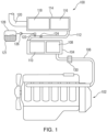
- FIGS. 1 and 2 are representations of an exhaust after-treatment system 100, which is known in the art.
- the system 100 includes a first module 104 that is fluidly connected to an exhaust conduit 106 of the engine 102.
- the first module 104 is arranged to internally receive engine exhaust gas from the conduit 106.
- the first module 104 contains a diesel oxidation catalyst (DOC) 108 arranged in series, upstream from a diesel particulate filter (DPF) 110, each of which has a relatively large frame.
- DOC diesel oxidation catalyst
- DPF diesel particulate filter
- the CDPF 110 is a coated DPF (CDPF).
- Exhaust gas provided to the first module 104 by the engine 102 first passes through the DOC 108 and then through the CDPF 110 before entering a transfer conduit 112.
- the transfer conduit 112 fluidly interconnects the first module 104 with a second module 114 such that exhaust gas from the engine 102 may pass through the first and second modules 104 and 114 in series before being released at a stack 120 that is connected to the second module.
- the second module 114 encloses a SCR catalyst 116 and an Ammonia Oxidation Catalyst (AMOX) 118, each formed on its own respective substrate.
- the SCR catalyst 116 and AMOX 118 operate to treat exhaust gas from the engine 102 in the presence of ammonia, which is provided after degradation of DEF injected into the exhaust gas in the transfer conduit 112.
- a regeneration device 130 is disposed upstream of the first module 104 along the conduit 106.
- the regeneration device 130 which can be implemented as a fuel-fired heater, increases exhaust gas temperature for an active regeneration of the CDPF 110, selectively during operation as is known.
- the DEF 121 is injected into the transfer conduit 112 by a DEF injector 122.
- the DEF 121 is contained within a reservoir 128 and is provided to the DEF injector 122 by a pump 126.
- a mixer 124 may be disposed along the transfer conduit 112.
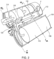
- FIG. 2 is a partially sectioned outline view of the system 100, where same or similar structures as corresponding structures previously described are denoted by the same reference numerals previously used for simplicity. As shown in FIG.
- the first and second modules 104 and 114 are disposed next to one another, with the transfer conduit 112 disposed between them.
- the DEF injector 122 is disposed on an upstream end of the transfer conduit 112 relative to a direction of exhaust gas flow, F.
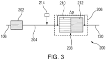
- FIG. 3 is a block diagram of an after-treatment system 200 in accordance with the invention.
- the system 200 is configured to replace the system 100 for the engine 102 ( FIG. 1 ) but without necessarily use of the regeneration device 130 and with a smaller package size, as will be described hereinafter.
- the system 200 includes a DOC 202, which in this embodiment has a smaller diameter and an overall smaller volume than the DOC 108 ( FIG. 1 ).
- the DOC 202 may optionally further include a relatively small NOx absorber to improve flow temperature of exhaust gas temperature flowing there through.
- the system 200 is arranged such that the exhaust conduit 106 from the engine 102 ( FIG. 1 ) provides exhaust gas from the engine 102 to the DOC 202, which operates in the known fashion.
- a transfer conduit 204 fluidly interconnects the DOC 202 to a treatment module 206, which is connected to the stack 120 (also see FIG. 1 ) either directly or through a muffler (not shown).
- the treatment module 206 includes a series-compact device 208, which in the illustrated embodiment includes a DPF 210, and a combined SCR plus AMOx (SCR/AMOx) 212.
- a DEF injector 214 is disposed along the transfer conduit 204 and arranged to inject DEF therein between the DOC 202 and the series-compact device 208 during operation such that injection of DEF occurs downstream of the DOC 202 and upstream of the series-compact device 208.
- the DPF 210 in the illustrated embodiment is a monolithic, wall-flow type substrate that is made from advanced cordierite (AC) or aluminum titanate (AT) having an asymmetric channel (ACT) construction with larger inlet and smaller outlet channels.
- the DPF 210 shown has about 47 channels per cm 2 (300 channels per square inch (cpsi)) and is uncoated, uncatalyzed or includes a hydrolysis coating.
- the DOC 202 creates NO 2 from NO and O 2 present in the exhaust stream.
- the NO 2 created by the DOC 202 is carried to the DPF 210 to support a passive regeneration of the DPF 210 at a relatively low temperature of about 200 def. C.
- the SCR/AMOx 212 of the system 200 in the illustrated embodiment is built on a substrate having about 93 channels per cm 2 (600 cpsi) that is physically connected to the substrate of the DPF 210 or is otherwise in close proximity thereto within the treatment module 206 to act as a single substrate.
- the system 200 operates to remove more than 98% of engine soot on a mass or particulate count basis, and reduces NOx by more than 96% on a mass basis.
- the after-treatment system 200 may include additional or alternative structures for treating the exhaust gas stream provided from the engine 102.
- a soot-reducing, soot-filtering or soot-removing device such as an electrostatic precipitator, a plasma burner or any other known soot-removing device may be used instead of, or in addition to, the DPF 210 in the after-treatment system 200.
- soot-reducing device is contemplated to include any structure that operates to at least partially remove soot and/or other particulates from an exhaust stream of an engine as the exhaust stream passes through, over or around the soot-reducing device.
- the after-treatment system 200 may be configured and/or sized to remove an optimized fraction of soot, for example, between 10% and 90% on a mass or particulate count basis, and to reduce NOx by an optimized fraction, for example, more than 70% on a mass basis, from the flow of exhaust from the engine.
- This disclosure relates to after-treatment systems for diesel engines used alone or in conjunction with other power sources and types in a machine. More particularly, the disclosure describes use of an uncatalyzed or hydrolysis coated low backpressure DPF, which allows DEF dosing upstream of a single can with a series DPF and SCR catalyst.
- DPF uncatalyzed or hydrolysis coated low backpressure
- One challenge in designing and integrating a combined DPF/SCR system for an engine in a machine is the requirement for DEF injection to be downstream of the DOC or a catalyzed DPF to avoid ammonia oxidation to NOx.
- the described embodiments advantageously reduce package size and weight for the after-treatment devices as compared with known systems while maintaining passive soot oxidation capability, i.e., the ability to avoid using active DPF regeneration, which avoid the cost, complexity and fuel consumption increase associated with active regeneration.
- the described systems and methods therefore, provide greater flexibility than known systems have to integrate low or high temperature thermal management.
- the systems in accordance with the disclosure provide the capability of moving or relocating the DPF from in-series with the DOC, as is the case in known systems, to a remote location, for example, on the engine. This flexibility also allows the DOC aspect ratio to be optimized for packaging resulting in considerable height and width reductions of 15% or more as compared to previously known systems. Overall, the disclosed systems and methods provide a compact, high efficiency package that works with low or high temperature DPF regeneration.
- the present disclosure is applicable to internal combustion engines operating in mobile or stationary applications.
- the disclosed systems are advantageously more compact the systems having comparable emission constituent abatement performance.
- the systems in accordance with the present disclosure are simpler and more cost effective to operate in that the DPF used is suitable for both passive and active regeneration, which makes use of an active regeneration device optional.
- the DPF 210 and SCR/AMOx 212 may have a diameter that is comparable to the SCR catalyst 116 and AMOX 118 ( FIG. 1 )
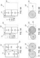
- the combined series-compact device 208 has an overall length that is quite shorter than the overall combined substrate length of all devices used in the system 100 ( FIG. 1 ), which greatly reduces the overall package size of the various systems. This is discussed below relative to FIGS. 4A and 4B as compared to FIGS. 5A, 5B, 6A and 6B .
- FIG. 4A qualitatively shows a packaging envelope 302 for the components of the system 100 ( FIG. 1 ), in block form, from a top perspective
- FIG. 4B shows the packaging envelope 302 from a front perspective.
- a footprint of the packaging envelope 302 is defined by the space that is required to accommodate arrangement of the DOC 108 and CDPF 110 on the right side, and the SCR catalyst 116 and AMOx 118 on the left side of FIG. 4A in the orientation shown.
- a cross sectional area of the packaging envelope 302 is similarly defined by the diameters of the various substrates mentioned above, as well as by the diameter of the transfer conduit 112, as shown in FIG. 4B .
- FIGS. 5A and 5B show the components of the system 200 in accordance with the invention arranged within the packaging envelope 302 of the system 100 for comparison and to illustrate the space-saving nature of the system 200 over the system 100.
- the arrangement of the smaller-diameter DOC 202 allows the centerline of the series-combined substrates for the DPF 210 and the SCR/AMOx 212 to move closer to a centerline of the DOC 202, which results in an overall narrower combined width for these components and more space being available to route the transfer conduit 112. Therefore, and as can be seen from FIGS. 5A and 5B , the volume 304 required to contain or package the system 200 is about 15% less than the volume occupied by the packaging envelope 302, with additional space being available around the components to route other machine components, add shielding, and the like.
- FIGS. 6A and 6B show the components of the system in accordance with an alternative embodiment of the invention, in which the DOC 202 is mounted remotely from the remaining components of the system 200, for example, on the engine or anywhere along the exhaust conduit supplying exhaust gas from the engine to the system 200.
- the DOC 202 is placed outside from the packaging envelope 302 due to its remote mounting.
- the series-combined substrates for the DPF 210 and the SCR/AMOx 212 are moved to one side of the envelope thus reducing the volume 306 required to contain or package the system 200 by about 50% or more relative to the volume occupied by the packaging envelope 302.
- FIG. 7 A qualitative graph showing the soot loading in the DPF of the system 200 as compared to the system 100 over time is shown in FIG. 7 .
- the horizontal axis 308 represents time, for example, in hours
- the vertical axis 310 represents soot loading, for example, as a percentage of a critical soot loading 312 at which the DPF plugging with soot particles is beyond a desired extent and may render the DPF essentially plugged.
- the graph shows two curves, a first curve 314 and a second curve 316.
- the first curve 314 represents a soot loading over time of the CDPF 110 ( FIG. 1 ) of the system 100, which is considered as the baseline system.
- the second curve 316 represents a soot loading over time of the DPF 210 of the system 200 ( FIG. 3 ) of the system 200 in accordance with the disclosure.
- the soot loading in both DPFs increases initially before stabilizing and reaching a balance point over time because in both systems 100, 200 the DPF continuously regenerates during operation and reaches a steady-state soot loading.
- the loading in the DPF 210 in the system 200 settles at a soot loading that is higher than the corresponding soot loading in the CDPF 110 in the system 100.
- the soot loading in the DPF 210 is higher than the loading in the CDPF 110, both are still below the critical soot loading 312.
- the higher soot loading in the DPF 210 which may increase the pressure drop across the DPF, will not appreciably affect engine operation given the relatively higher cell density of the SCR/AMOx 212 used in the system 200 as compared to the system 100.
Landscapes
- Engineering & Computer Science (AREA)
- Chemical & Material Sciences (AREA)
- Combustion & Propulsion (AREA)
- Chemical Kinetics & Catalysis (AREA)
- Mechanical Engineering (AREA)
- General Engineering & Computer Science (AREA)
- Health & Medical Sciences (AREA)
- Toxicology (AREA)
- Biomedical Technology (AREA)
- Environmental & Geological Engineering (AREA)
- Analytical Chemistry (AREA)
- General Chemical & Material Sciences (AREA)
- Oil, Petroleum & Natural Gas (AREA)
- Materials Engineering (AREA)
- Exhaust Gas After Treatment (AREA)
- Processes For Solid Components From Exhaust (AREA)
Claims (8)
- Nachbehandlungssystem (200) zur Verwendung mit einem Motor (102), wobei der Motor (102) eine Abgasleitung (106) aufweist, wobei die Abgasleitung (106) angepasst ist, um einen Abgasstrom von dem Motor (102) während eines Betriebs des Motors (102) zu leiten, wobei das Nachbehandlungssystem (200) für eine Verbindung mit der Abgasleitung (106) angepasst und angeordnet ist, um den Abgasstrom von dem Motor (102) aufzunehmen und zu behandeln, das Nachbehandlungssystem (200) umfassend:einen Dieseloxidationskatalysator, DOC, (202), der mit der Abgasleitung (106) verbunden und angeordnet ist, um den Abgasstrom von dem Motor (102) aufzunehmen;eine Transferleitung (204), die in einem nachgelagerten Ende des DOC (202) verbunden ist;eine Abgabevorrichtung (214) für Dieselabgasfluid, DEF, (121), die mit der Transferleitung (204) verknüpft und angepasst ist, um das DEF (121) in die Transferleitung (204) selektiv einzuspritzen, um in einer nachgelagerten Richtung mittels Gas, das während des Betriebs des Motors (102) durch die Transferleitung (204) läuft, getragen zu werden; undeine Reihenkompaktvorrichtung (208), umfassend:eine Rußreduzierungsvorrichtung (210), umfassend ein Substrat und die mit einem nachgelagerten Ende der Transferleitung (204) verbunden ist, wobei die Rußreduzierungsvorrichtung (210) angeordnet ist, um das Gas, das während des Betriebs des Motors (102) durch die Transferleitung (204) läuft, aufzunehmen; undein kombinierter Katalysator (212) für selektive katalytische Reduktion, SCR, plus Ammoniakoxidation, AMOx, wobei der AMOx-Katalysator als eine Beschichtung an dem SCR-Katalysator (212) ausgebildet ist, wobei der kombinierte SCR/AMOx-Katalysator (212) ein Substrat umfasst, das mit einem nachgelagerten Ende des Substrats der Rußreduzierungsvorrichtung (210) gegenüber der Transferleitung (204) physisch verbunden ist, wobei der SCR-Katalysator (212) angeordnet ist, um das Gas, das durch die Rußreduzierungsvorrichtung (210) während des Betriebs des Motors (102) läuft, aufzunehmen;wobei die Rußreduzierungsvorrichtung (210) ein Dieselpartikelfilter, DPF, ist, der aus einem monolithischen Substrat einer Dünnwandstromart hergestellt ist, das aus fortschrittlichem Cordierit, AC, oder Aluminiumtitanat, AT, hergestellt ist, und eine asymmetrische Kanalkonstruktion, ACT-Konstruktion, derart aufweist, dass eine Größe von Einlasskanälen des DPF (210) größer als eine Größe von Auslasskanälen des DPF (210) ist.
- Nachbehandlungssystem (200) nach Anspruch 1, wobei die Rußreduzierungsvorrichtung mindestens eines ist von:nicht katalysiert;unbeschichtet;eine Hydrolysebeschichtung einschließt; undeinen Hydrolysekatalysator einschließt.
- Nachbehandlungssystem (200) nach Anspruch 1, wobei das Substrat des DPF (210) etwa 47 Kanäle pro cm2 (300 Kanäle pro Quadratzoll) aufweist.
- Nachbehandlungssystem (200) nach Anspruch 1, wobei das Substrat des kombinierten SCR/AMOx-Katalysators (212) etwa 93 Kanäle pro cm2 (600 Kanäle pro Quadratzoll) aufweist, und wobei das Substrat des SCR-Katalysators (212) in einem gemeinsamen Gehäuse (206) mit dem Substrat der Rußreduzierungsvorrichtung (210) eingebaut ist.
- Nachbehandlungssystem (200) nach Anspruch 1, wobei jedes von dem DOC (202), der Rußreduzierungsvorrichtung (210) und dem SCR-Katalysator (212) eine im Allgemeinen zylindrische Form aufweist, die einen jeweiligen Außendurchmesser aufweist, und wobei ein Durchmesser des DOC (202) kleiner als ein Durchmesser der Rußreduzierungsvorrichtung (210) und ein Durchmesser des SCR-Katalysators (212) ist.
- Nachbehandlungssystem (200) nach Anspruch 1, wobei ein Gasstrom durch das Nachbehandlungssystem (200) definiert ist, der an dem Motor (102) beginnt, durch den DOC (202) läuft, durch die Transferleitung (204) und vorbei an der DEF-Abgabevorrichtung (214) läuft, durch die Rußreduzierungsvorrichtung (210) läuft und durch den SCR-Katalysator (212) läuft.
- Nachbehandlungssystem (200) nach Anspruch 1, wobei der DOC (202) näher an dem Motor (102) als an der Rußreduzierungsvorrichtung (210) montiert ist.
- Nachbehandlungssystem (200) nach Anspruch 1, wobei der Dieselpartikelfilter, DPF, für eine passive Regeneration bei einer Temperatur von etwa 200 Grad C konfiguriert ist.
Applications Claiming Priority (2)
| Application Number | Priority Date | Filing Date | Title |
|---|---|---|---|
| US15/080,841 US9879581B2 (en) | 2016-03-25 | 2016-03-25 | After-treatment system |
| PCT/US2017/022672 WO2017165184A1 (en) | 2016-03-25 | 2017-03-16 | Exhaust after-treatment system |
Publications (2)
| Publication Number | Publication Date |
|---|---|
| EP3433475A1 EP3433475A1 (de) | 2019-01-30 |
| EP3433475B1 true EP3433475B1 (de) | 2023-05-03 |
Family
ID=58428406
Family Applications (1)
| Application Number | Title | Priority Date | Filing Date |
|---|---|---|---|
| EP17714112.4A Active EP3433475B1 (de) | 2016-03-25 | 2017-03-16 | Abgasnachbehandlungssystem |
Country Status (4)
| Country | Link |
|---|---|
| US (1) | US9879581B2 (de) |
| EP (1) | EP3433475B1 (de) |
| CN (1) | CN108779694A (de) |
| WO (1) | WO2017165184A1 (de) |
Families Citing this family (10)
| Publication number | Priority date | Publication date | Assignee | Title |
|---|---|---|---|---|
| CN108150250A (zh) * | 2018-01-04 | 2018-06-12 | 中国第汽车股份有限公司 | 一种集成式后处理设备 |
| WO2020083260A1 (zh) * | 2018-10-24 | 2020-04-30 | 欧普照明股份有限公司 | 一种照明灯具 |
| US11268418B2 (en) | 2019-01-18 | 2022-03-08 | Caterpillar Inc. | Engine system and operating strategy for selective in situ and ex situ limiting of NOx production |
| CN109653853B (zh) * | 2019-01-28 | 2020-12-18 | 江苏大学 | 柴油机尾气联合处理系统与控制方法 |
| US11156143B2 (en) | 2019-10-28 | 2021-10-26 | Caterpillar Inc. | Aftertreatment system and method |
| US11143078B2 (en) | 2019-12-17 | 2021-10-12 | Caterpillar Inc. | Aftertreatment system and method |
| CN111255550A (zh) * | 2020-01-21 | 2020-06-09 | 中国重汽集团济南动力有限公司 | 一种柴油国六后处理器总成 |
| CN111845772A (zh) * | 2020-05-27 | 2020-10-30 | 联合汽车电子有限公司 | Gpf主动再生方法、电子设备及可读存储介质 |
| CN112727567B (zh) * | 2020-12-15 | 2023-03-10 | 济南大学 | 柴油机用颗粒物过滤器及其在一体化减少柴油机冷启动阶段NOx和碳烟颗粒排放中的应用 |
| CN113756920B (zh) * | 2021-09-29 | 2024-03-19 | 广西玉柴机器股份有限公司 | 一种柴油发动机测试台架尾气处理控制装置 |
Citations (3)
| Publication number | Priority date | Publication date | Assignee | Title |
|---|---|---|---|---|
| US20050066639A1 (en) * | 2003-09-25 | 2005-03-31 | Frost Rodney I. | Asymmetric honeycomb wall-flow filter having improved structural strength |
| US20090173063A1 (en) * | 2008-01-07 | 2009-07-09 | Boorse R Samuel | Mitigation of Particulates and NOx in Engine Exhaust |
| US20110271664A1 (en) * | 2010-05-05 | 2011-11-10 | Basf Corporation | Integrated SCR and AMOX Catalyst Systems |
Family Cites Families (17)
| Publication number | Priority date | Publication date | Assignee | Title |
|---|---|---|---|---|
| US7229597B2 (en) * | 2003-08-05 | 2007-06-12 | Basfd Catalysts Llc | Catalyzed SCR filter and emission treatment system |
| US20070256407A1 (en) | 2006-05-05 | 2007-11-08 | Eaton Corporation | Reformer temperature control with leading temperature estimation |
| US20100077739A1 (en) * | 2008-09-30 | 2010-04-01 | Rodman Anthony C | Exhaust system implementing dual stage SCR |
| US8555617B2 (en) * | 2009-03-26 | 2013-10-15 | GM Global Technology Operations LLC | Exhaust gas treatment system including a four-way catalyst and urea SCR catalyst and method of using the same |
| US8904760B2 (en) | 2009-06-17 | 2014-12-09 | GM Global Technology Operations LLC | Exhaust gas treatment system including an HC-SCR and two-way catalyst and method of using the same |
| US20100326059A1 (en) | 2009-06-26 | 2010-12-30 | Gm Global Technology Operations, Inc. | Selective catalytic reduction exhaust aftertreatment system and engine incorporating the same |
| JP5630024B2 (ja) | 2010-01-25 | 2014-11-26 | いすゞ自動車株式会社 | ディーゼルエンジンの排気浄化装置及び排気浄化方法 |
| US8413432B2 (en) | 2010-06-30 | 2013-04-09 | GM Global Technology Operations LLC | Particulate filter regeneration interruption systems and methods |
| FR2968711B1 (fr) | 2010-12-14 | 2014-12-26 | Peugeot Citroen Automobiles Sa | Ligne d'echappement pour vehicule automobile et methode d'epuration de gaz d'echappement produits par un moteur thermique equipant ce vehicule |
| FR2971810B1 (fr) | 2011-02-18 | 2013-03-15 | Peugeot Citroen Automobiles Sa | Ensemble de post-traitement des gaz d'echappement d'un moteur a combustion suralimente, et vehicule automobile comportant un tel ensemble |
| DK177536B1 (en) | 2011-07-19 | 2013-09-16 | Ictalcare As | Method for detecting seizures |
| DE102012000591A1 (de) * | 2012-01-14 | 2013-07-18 | Daimler Ag | Motorblock-Anordnung mit einem Abgassystem |
| US8800275B2 (en) * | 2012-02-27 | 2014-08-12 | Caterpillar Inc. | Mounting assembly for a reductant injector |
| US9556770B2 (en) * | 2013-03-28 | 2017-01-31 | Yanmar Co., Ltd. | Engine device |
| US20140331645A1 (en) * | 2013-05-13 | 2014-11-13 | Caterpillar Inc. | System and Method for Injector Fault Remediation |
| DE102015000955B4 (de) | 2014-01-20 | 2025-01-23 | Cummins Inc. | Systeme und Verfahren zur Minderung von NOx- und HC-Emissionen |
| DE112014006379T5 (de) * | 2014-02-18 | 2016-11-24 | Faurecia Emissions Control Technologies, Usa, Llc | Plenumkammer für eine Abgasanlage |
-
2016
- 2016-03-25 US US15/080,841 patent/US9879581B2/en active Active
-
2017
- 2017-03-16 EP EP17714112.4A patent/EP3433475B1/de active Active
- 2017-03-16 CN CN201780017883.9A patent/CN108779694A/zh active Pending
- 2017-03-16 WO PCT/US2017/022672 patent/WO2017165184A1/en not_active Ceased
Patent Citations (3)
| Publication number | Priority date | Publication date | Assignee | Title |
|---|---|---|---|---|
| US20050066639A1 (en) * | 2003-09-25 | 2005-03-31 | Frost Rodney I. | Asymmetric honeycomb wall-flow filter having improved structural strength |
| US20090173063A1 (en) * | 2008-01-07 | 2009-07-09 | Boorse R Samuel | Mitigation of Particulates and NOx in Engine Exhaust |
| US20110271664A1 (en) * | 2010-05-05 | 2011-11-10 | Basf Corporation | Integrated SCR and AMOX Catalyst Systems |
Also Published As
| Publication number | Publication date |
|---|---|
| US9879581B2 (en) | 2018-01-30 |
| CN108779694A (zh) | 2018-11-09 |
| EP3433475A1 (de) | 2019-01-30 |
| WO2017165184A1 (en) | 2017-09-28 |
| US20170276044A1 (en) | 2017-09-28 |
Similar Documents
| Publication | Publication Date | Title |
|---|---|---|
| EP3433475B1 (de) | Abgasnachbehandlungssystem | |
| US9458750B2 (en) | Integrated exhaust treatment device having compact configuration | |
| JP5630024B2 (ja) | ディーゼルエンジンの排気浄化装置及び排気浄化方法 | |
| EP2826974B1 (de) | Abgasreinigungsvorrichtung | |
| EP2530265B1 (de) | Abgasreinigungsvorrichtung und abgasreinigungsverfahren für einen dieselmotor | |
| US8978368B2 (en) | Exhaust-gas aftertreatment system and method for exhaust-gas aftertreatment | |
| CN102822464B (zh) | 内燃机排出气体的后处理装置 | |
| WO2016109321A1 (en) | Compact side inlet and outlet exhaust aftertreatment system | |
| US20170276053A1 (en) | After-Treatment System | |
| EP3438426B1 (de) | Abgasreinigungssystem | |
| US9957866B2 (en) | Exhaust treatment apparatus and method | |
| US10138795B2 (en) | Plenum chamber for exhaust system | |
| US8850801B2 (en) | Catalytic converter and muffler | |
| CN104121075A (zh) | 内燃发动机和排气后处理系统 | |
| US12291987B2 (en) | Exhaust treatment method and apparatus having particulate filters and SCR | |
| CN102168596A (zh) | 用于减少柴油发动机系统中的氮氧化物排放的设备 | |
| KR102316701B1 (ko) | 배기가스 후처리 장치 및 이를 포함하는 콤바인 | |
| CN113847123A (zh) | 车辆及其尾气后处理系统 | |
| WO2018057170A1 (en) | After-treatment system | |
| JP6729008B2 (ja) | 排気浄化装置 | |
| CN110770420A (zh) | 废气净化系统 |
Legal Events
| Date | Code | Title | Description |
|---|---|---|---|
| STAA | Information on the status of an ep patent application or granted ep patent |
Free format text: STATUS: UNKNOWN |
|
| STAA | Information on the status of an ep patent application or granted ep patent |
Free format text: STATUS: THE INTERNATIONAL PUBLICATION HAS BEEN MADE |
|
| PUAI | Public reference made under article 153(3) epc to a published international application that has entered the european phase |
Free format text: ORIGINAL CODE: 0009012 |
|
| STAA | Information on the status of an ep patent application or granted ep patent |
Free format text: STATUS: REQUEST FOR EXAMINATION WAS MADE |
|
| 17P | Request for examination filed |
Effective date: 20180823 |
|
| AK | Designated contracting states |
Kind code of ref document: A1 Designated state(s): AL AT BE BG CH CY CZ DE DK EE ES FI FR GB GR HR HU IE IS IT LI LT LU LV MC MK MT NL NO PL PT RO RS SE SI SK SM TR |
|
| AX | Request for extension of the european patent |
Extension state: BA ME |
|
| DAV | Request for validation of the european patent (deleted) | ||
| DAX | Request for extension of the european patent (deleted) | ||
| STAA | Information on the status of an ep patent application or granted ep patent |
Free format text: STATUS: EXAMINATION IS IN PROGRESS |
|
| 17Q | First examination report despatched |
Effective date: 20200508 |
|
| GRAP | Despatch of communication of intention to grant a patent |
Free format text: ORIGINAL CODE: EPIDOSNIGR1 |
|
| STAA | Information on the status of an ep patent application or granted ep patent |
Free format text: STATUS: GRANT OF PATENT IS INTENDED |
|
| INTG | Intention to grant announced |
Effective date: 20221214 |
|
| GRAS | Grant fee paid |
Free format text: ORIGINAL CODE: EPIDOSNIGR3 |
|
| GRAA | (expected) grant |
Free format text: ORIGINAL CODE: 0009210 |
|
| STAA | Information on the status of an ep patent application or granted ep patent |
Free format text: STATUS: THE PATENT HAS BEEN GRANTED |
|
| AK | Designated contracting states |
Kind code of ref document: B1 Designated state(s): AL AT BE BG CH CY CZ DE DK EE ES FI FR GB GR HR HU IE IS IT LI LT LU LV MC MK MT NL NO PL PT RO RS SE SI SK SM TR |
|
| REG | Reference to a national code |
Ref country code: GB Ref legal event code: FG4D |
|
| REG | Reference to a national code |
Ref country code: AT Ref legal event code: REF Ref document number: 1564766 Country of ref document: AT Kind code of ref document: T Effective date: 20230515 Ref country code: CH Ref legal event code: EP |
|
| REG | Reference to a national code |
Ref country code: DE Ref legal event code: R096 Ref document number: 602017068276 Country of ref document: DE |
|
| REG | Reference to a national code |
Ref country code: IE Ref legal event code: FG4D |
|
| REG | Reference to a national code |
Ref country code: LT Ref legal event code: MG9D |
|
| REG | Reference to a national code |
Ref country code: NL Ref legal event code: MP Effective date: 20230503 |
|
| REG | Reference to a national code |
Ref country code: AT Ref legal event code: MK05 Ref document number: 1564766 Country of ref document: AT Kind code of ref document: T Effective date: 20230503 |
|
| PG25 | Lapsed in a contracting state [announced via postgrant information from national office to epo] |
Ref country code: SE Free format text: LAPSE BECAUSE OF FAILURE TO SUBMIT A TRANSLATION OF THE DESCRIPTION OR TO PAY THE FEE WITHIN THE PRESCRIBED TIME-LIMIT Effective date: 20230503 Ref country code: PT Free format text: LAPSE BECAUSE OF FAILURE TO SUBMIT A TRANSLATION OF THE DESCRIPTION OR TO PAY THE FEE WITHIN THE PRESCRIBED TIME-LIMIT Effective date: 20230904 Ref country code: NO Free format text: LAPSE BECAUSE OF FAILURE TO SUBMIT A TRANSLATION OF THE DESCRIPTION OR TO PAY THE FEE WITHIN THE PRESCRIBED TIME-LIMIT Effective date: 20230803 Ref country code: NL Free format text: LAPSE BECAUSE OF FAILURE TO SUBMIT A TRANSLATION OF THE DESCRIPTION OR TO PAY THE FEE WITHIN THE PRESCRIBED TIME-LIMIT Effective date: 20230503 Ref country code: ES Free format text: LAPSE BECAUSE OF FAILURE TO SUBMIT A TRANSLATION OF THE DESCRIPTION OR TO PAY THE FEE WITHIN THE PRESCRIBED TIME-LIMIT Effective date: 20230503 Ref country code: AT Free format text: LAPSE BECAUSE OF FAILURE TO SUBMIT A TRANSLATION OF THE DESCRIPTION OR TO PAY THE FEE WITHIN THE PRESCRIBED TIME-LIMIT Effective date: 20230503 |
|
| PG25 | Lapsed in a contracting state [announced via postgrant information from national office to epo] |
Ref country code: RS Free format text: LAPSE BECAUSE OF FAILURE TO SUBMIT A TRANSLATION OF THE DESCRIPTION OR TO PAY THE FEE WITHIN THE PRESCRIBED TIME-LIMIT Effective date: 20230503 Ref country code: PL Free format text: LAPSE BECAUSE OF FAILURE TO SUBMIT A TRANSLATION OF THE DESCRIPTION OR TO PAY THE FEE WITHIN THE PRESCRIBED TIME-LIMIT Effective date: 20230503 Ref country code: LV Free format text: LAPSE BECAUSE OF FAILURE TO SUBMIT A TRANSLATION OF THE DESCRIPTION OR TO PAY THE FEE WITHIN THE PRESCRIBED TIME-LIMIT Effective date: 20230503 Ref country code: LT Free format text: LAPSE BECAUSE OF FAILURE TO SUBMIT A TRANSLATION OF THE DESCRIPTION OR TO PAY THE FEE WITHIN THE PRESCRIBED TIME-LIMIT Effective date: 20230503 Ref country code: IS Free format text: LAPSE BECAUSE OF FAILURE TO SUBMIT A TRANSLATION OF THE DESCRIPTION OR TO PAY THE FEE WITHIN THE PRESCRIBED TIME-LIMIT Effective date: 20230903 Ref country code: HR Free format text: LAPSE BECAUSE OF FAILURE TO SUBMIT A TRANSLATION OF THE DESCRIPTION OR TO PAY THE FEE WITHIN THE PRESCRIBED TIME-LIMIT Effective date: 20230503 Ref country code: GR Free format text: LAPSE BECAUSE OF FAILURE TO SUBMIT A TRANSLATION OF THE DESCRIPTION OR TO PAY THE FEE WITHIN THE PRESCRIBED TIME-LIMIT Effective date: 20230804 |
|
| PG25 | Lapsed in a contracting state [announced via postgrant information from national office to epo] |
Ref country code: FI Free format text: LAPSE BECAUSE OF FAILURE TO SUBMIT A TRANSLATION OF THE DESCRIPTION OR TO PAY THE FEE WITHIN THE PRESCRIBED TIME-LIMIT Effective date: 20230503 |
|
| PG25 | Lapsed in a contracting state [announced via postgrant information from national office to epo] |
Ref country code: SK Free format text: LAPSE BECAUSE OF FAILURE TO SUBMIT A TRANSLATION OF THE DESCRIPTION OR TO PAY THE FEE WITHIN THE PRESCRIBED TIME-LIMIT Effective date: 20230503 |
|
| PG25 | Lapsed in a contracting state [announced via postgrant information from national office to epo] |
Ref country code: SM Free format text: LAPSE BECAUSE OF FAILURE TO SUBMIT A TRANSLATION OF THE DESCRIPTION OR TO PAY THE FEE WITHIN THE PRESCRIBED TIME-LIMIT Effective date: 20230503 Ref country code: SK Free format text: LAPSE BECAUSE OF FAILURE TO SUBMIT A TRANSLATION OF THE DESCRIPTION OR TO PAY THE FEE WITHIN THE PRESCRIBED TIME-LIMIT Effective date: 20230503 Ref country code: RO Free format text: LAPSE BECAUSE OF FAILURE TO SUBMIT A TRANSLATION OF THE DESCRIPTION OR TO PAY THE FEE WITHIN THE PRESCRIBED TIME-LIMIT Effective date: 20230503 Ref country code: EE Free format text: LAPSE BECAUSE OF FAILURE TO SUBMIT A TRANSLATION OF THE DESCRIPTION OR TO PAY THE FEE WITHIN THE PRESCRIBED TIME-LIMIT Effective date: 20230503 Ref country code: DK Free format text: LAPSE BECAUSE OF FAILURE TO SUBMIT A TRANSLATION OF THE DESCRIPTION OR TO PAY THE FEE WITHIN THE PRESCRIBED TIME-LIMIT Effective date: 20230503 Ref country code: CZ Free format text: LAPSE BECAUSE OF FAILURE TO SUBMIT A TRANSLATION OF THE DESCRIPTION OR TO PAY THE FEE WITHIN THE PRESCRIBED TIME-LIMIT Effective date: 20230503 |
|
| REG | Reference to a national code |
Ref country code: DE Ref legal event code: R097 Ref document number: 602017068276 Country of ref document: DE |
|
| PLBE | No opposition filed within time limit |
Free format text: ORIGINAL CODE: 0009261 |
|
| STAA | Information on the status of an ep patent application or granted ep patent |
Free format text: STATUS: NO OPPOSITION FILED WITHIN TIME LIMIT |
|
| 26N | No opposition filed |
Effective date: 20240206 |
|
| PG25 | Lapsed in a contracting state [announced via postgrant information from national office to epo] |
Ref country code: SI Free format text: LAPSE BECAUSE OF FAILURE TO SUBMIT A TRANSLATION OF THE DESCRIPTION OR TO PAY THE FEE WITHIN THE PRESCRIBED TIME-LIMIT Effective date: 20230503 |
|
| PG25 | Lapsed in a contracting state [announced via postgrant information from national office to epo] |
Ref country code: SI Free format text: LAPSE BECAUSE OF FAILURE TO SUBMIT A TRANSLATION OF THE DESCRIPTION OR TO PAY THE FEE WITHIN THE PRESCRIBED TIME-LIMIT Effective date: 20230503 Ref country code: IT Free format text: LAPSE BECAUSE OF FAILURE TO SUBMIT A TRANSLATION OF THE DESCRIPTION OR TO PAY THE FEE WITHIN THE PRESCRIBED TIME-LIMIT Effective date: 20230503 |
|
| REG | Reference to a national code |
Ref country code: CH Ref legal event code: PL |
|
| PG25 | Lapsed in a contracting state [announced via postgrant information from national office to epo] |
Ref country code: BG Free format text: LAPSE BECAUSE OF FAILURE TO SUBMIT A TRANSLATION OF THE DESCRIPTION OR TO PAY THE FEE WITHIN THE PRESCRIBED TIME-LIMIT Effective date: 20230503 |
|
| PG25 | Lapsed in a contracting state [announced via postgrant information from national office to epo] |
Ref country code: LU Free format text: LAPSE BECAUSE OF NON-PAYMENT OF DUE FEES Effective date: 20240316 |
|
| PG25 | Lapsed in a contracting state [announced via postgrant information from national office to epo] |
Ref country code: MC Free format text: LAPSE BECAUSE OF FAILURE TO SUBMIT A TRANSLATION OF THE DESCRIPTION OR TO PAY THE FEE WITHIN THE PRESCRIBED TIME-LIMIT Effective date: 20230503 |
|
| PG25 | Lapsed in a contracting state [announced via postgrant information from national office to epo] |
Ref country code: MC Free format text: LAPSE BECAUSE OF FAILURE TO SUBMIT A TRANSLATION OF THE DESCRIPTION OR TO PAY THE FEE WITHIN THE PRESCRIBED TIME-LIMIT Effective date: 20230503 Ref country code: LU Free format text: LAPSE BECAUSE OF NON-PAYMENT OF DUE FEES Effective date: 20240316 Ref country code: BG Free format text: LAPSE BECAUSE OF FAILURE TO SUBMIT A TRANSLATION OF THE DESCRIPTION OR TO PAY THE FEE WITHIN THE PRESCRIBED TIME-LIMIT Effective date: 20230503 |
|
| REG | Reference to a national code |
Ref country code: BE Ref legal event code: MM Effective date: 20240331 |
|
| PG25 | Lapsed in a contracting state [announced via postgrant information from national office to epo] |
Ref country code: BE Free format text: LAPSE BECAUSE OF NON-PAYMENT OF DUE FEES Effective date: 20240331 |
|
| PG25 | Lapsed in a contracting state [announced via postgrant information from national office to epo] |
Ref country code: FR Free format text: LAPSE BECAUSE OF NON-PAYMENT OF DUE FEES Effective date: 20240331 |
|
| PG25 | Lapsed in a contracting state [announced via postgrant information from national office to epo] |
Ref country code: IE Free format text: LAPSE BECAUSE OF NON-PAYMENT OF DUE FEES Effective date: 20240316 |
|
| PG25 | Lapsed in a contracting state [announced via postgrant information from national office to epo] |
Ref country code: IE Free format text: LAPSE BECAUSE OF NON-PAYMENT OF DUE FEES Effective date: 20240316 Ref country code: FR Free format text: LAPSE BECAUSE OF NON-PAYMENT OF DUE FEES Effective date: 20240331 Ref country code: BE Free format text: LAPSE BECAUSE OF NON-PAYMENT OF DUE FEES Effective date: 20240331 Ref country code: CH Free format text: LAPSE BECAUSE OF NON-PAYMENT OF DUE FEES Effective date: 20240331 |
|
| PGFP | Annual fee paid to national office [announced via postgrant information from national office to epo] |
Ref country code: DE Payment date: 20250218 Year of fee payment: 9 |
|
| PGFP | Annual fee paid to national office [announced via postgrant information from national office to epo] |
Ref country code: GB Payment date: 20250221 Year of fee payment: 9 |
|
| PG25 | Lapsed in a contracting state [announced via postgrant information from national office to epo] |
Ref country code: CY Free format text: LAPSE BECAUSE OF FAILURE TO SUBMIT A TRANSLATION OF THE DESCRIPTION OR TO PAY THE FEE WITHIN THE PRESCRIBED TIME-LIMIT; INVALID AB INITIO Effective date: 20170316 |
|
| PG25 | Lapsed in a contracting state [announced via postgrant information from national office to epo] |
Ref country code: HU Free format text: LAPSE BECAUSE OF FAILURE TO SUBMIT A TRANSLATION OF THE DESCRIPTION OR TO PAY THE FEE WITHIN THE PRESCRIBED TIME-LIMIT; INVALID AB INITIO Effective date: 20170316 |
|
| PG25 | Lapsed in a contracting state [announced via postgrant information from national office to epo] |
Ref country code: TR Free format text: LAPSE BECAUSE OF FAILURE TO SUBMIT A TRANSLATION OF THE DESCRIPTION OR TO PAY THE FEE WITHIN THE PRESCRIBED TIME-LIMIT Effective date: 20230503 |