EP3432050B1 - Anzeigeabbildungssystem und -verfahren sowie fahrzeug mit der system - Google Patents
Anzeigeabbildungssystem und -verfahren sowie fahrzeug mit der system Download PDFInfo
- Publication number
- EP3432050B1 EP3432050B1 EP17765678.2A EP17765678A EP3432050B1 EP 3432050 B1 EP3432050 B1 EP 3432050B1 EP 17765678 A EP17765678 A EP 17765678A EP 3432050 B1 EP3432050 B1 EP 3432050B1
- Authority
- EP
- European Patent Office
- Prior art keywords
- light
- polarized light
- bands
- transflective film
- angle
- Prior art date
- Legal status (The legal status is an assumption and is not a legal conclusion. Google has not performed a legal analysis and makes no representation as to the accuracy of the status listed.)
- Active
Links
Images


Classifications
-
- G—PHYSICS
- G02—OPTICS
- G02B—OPTICAL ELEMENTS, SYSTEMS OR APPARATUS
- G02B27/00—Optical systems or apparatus not provided for by any of the groups G02B1/00 - G02B26/00, G02B30/00
- G02B27/01—Head-up displays
- G02B27/0101—Head-up displays characterised by optical features
-
- B—PERFORMING OPERATIONS; TRANSPORTING
- B60—VEHICLES IN GENERAL
- B60K—ARRANGEMENT OR MOUNTING OF PROPULSION UNITS OR OF TRANSMISSIONS IN VEHICLES; ARRANGEMENT OR MOUNTING OF PLURAL DIVERSE PRIME-MOVERS IN VEHICLES; AUXILIARY DRIVES FOR VEHICLES; INSTRUMENTATION OR DASHBOARDS FOR VEHICLES; ARRANGEMENTS IN CONNECTION WITH COOLING, AIR INTAKE, GAS EXHAUST OR FUEL SUPPLY OF PROPULSION UNITS IN VEHICLES
- B60K35/00—Instruments specially adapted for vehicles; Arrangement of instruments in or on vehicles
- B60K35/20—Output arrangements, i.e. from vehicle to user, associated with vehicle functions or specially adapted therefor
- B60K35/21—Output arrangements, i.e. from vehicle to user, associated with vehicle functions or specially adapted therefor using visual output, e.g. blinking lights or matrix displays
- B60K35/23—Head-up displays [HUD]
-
- G—PHYSICS
- G02—OPTICS
- G02B—OPTICAL ELEMENTS, SYSTEMS OR APPARATUS
- G02B27/00—Optical systems or apparatus not provided for by any of the groups G02B1/00 - G02B26/00, G02B30/00
- G02B27/01—Head-up displays
-
- G—PHYSICS
- G02—OPTICS
- G02B—OPTICAL ELEMENTS, SYSTEMS OR APPARATUS
- G02B27/00—Optical systems or apparatus not provided for by any of the groups G02B1/00 - G02B26/00, G02B30/00
- G02B27/10—Beam splitting or combining systems
- G02B27/14—Beam splitting or combining systems operating by reflection only
- G02B27/144—Beam splitting or combining systems operating by reflection only using partially transparent surfaces without spectral selectivity
-
- G—PHYSICS
- G02—OPTICS
- G02B—OPTICAL ELEMENTS, SYSTEMS OR APPARATUS
- G02B5/00—Optical elements other than lenses
- G02B5/30—Polarising elements
-
- B—PERFORMING OPERATIONS; TRANSPORTING
- B60—VEHICLES IN GENERAL
- B60K—ARRANGEMENT OR MOUNTING OF PROPULSION UNITS OR OF TRANSMISSIONS IN VEHICLES; ARRANGEMENT OR MOUNTING OF PLURAL DIVERSE PRIME-MOVERS IN VEHICLES; AUXILIARY DRIVES FOR VEHICLES; INSTRUMENTATION OR DASHBOARDS FOR VEHICLES; ARRANGEMENTS IN CONNECTION WITH COOLING, AIR INTAKE, GAS EXHAUST OR FUEL SUPPLY OF PROPULSION UNITS IN VEHICLES
- B60K2360/00—Indexing scheme associated with groups B60K35/00 or B60K37/00 relating to details of instruments or dashboards
- B60K2360/20—Optical features of instruments
- B60K2360/27—Optical features of instruments using semi-transparent optical elements
-
- B—PERFORMING OPERATIONS; TRANSPORTING
- B60—VEHICLES IN GENERAL
- B60K—ARRANGEMENT OR MOUNTING OF PROPULSION UNITS OR OF TRANSMISSIONS IN VEHICLES; ARRANGEMENT OR MOUNTING OF PLURAL DIVERSE PRIME-MOVERS IN VEHICLES; AUXILIARY DRIVES FOR VEHICLES; INSTRUMENTATION OR DASHBOARDS FOR VEHICLES; ARRANGEMENTS IN CONNECTION WITH COOLING, AIR INTAKE, GAS EXHAUST OR FUEL SUPPLY OF PROPULSION UNITS IN VEHICLES
- B60K2360/00—Indexing scheme associated with groups B60K35/00 or B60K37/00 relating to details of instruments or dashboards
- B60K2360/20—Optical features of instruments
- B60K2360/33—Illumination features
- B60K2360/334—Projection means
-
- B—PERFORMING OPERATIONS; TRANSPORTING
- B60—VEHICLES IN GENERAL
- B60K—ARRANGEMENT OR MOUNTING OF PROPULSION UNITS OR OF TRANSMISSIONS IN VEHICLES; ARRANGEMENT OR MOUNTING OF PLURAL DIVERSE PRIME-MOVERS IN VEHICLES; AUXILIARY DRIVES FOR VEHICLES; INSTRUMENTATION OR DASHBOARDS FOR VEHICLES; ARRANGEMENTS IN CONNECTION WITH COOLING, AIR INTAKE, GAS EXHAUST OR FUEL SUPPLY OF PROPULSION UNITS IN VEHICLES
- B60K2360/00—Indexing scheme associated with groups B60K35/00 or B60K37/00 relating to details of instruments or dashboards
- B60K2360/60—Structural details of dashboards or instruments
- B60K2360/66—Projection screens or combiners
-
- B—PERFORMING OPERATIONS; TRANSPORTING
- B60—VEHICLES IN GENERAL
- B60K—ARRANGEMENT OR MOUNTING OF PROPULSION UNITS OR OF TRANSMISSIONS IN VEHICLES; ARRANGEMENT OR MOUNTING OF PLURAL DIVERSE PRIME-MOVERS IN VEHICLES; AUXILIARY DRIVES FOR VEHICLES; INSTRUMENTATION OR DASHBOARDS FOR VEHICLES; ARRANGEMENTS IN CONNECTION WITH COOLING, AIR INTAKE, GAS EXHAUST OR FUEL SUPPLY OF PROPULSION UNITS IN VEHICLES
- B60K2360/00—Indexing scheme associated with groups B60K35/00 or B60K37/00 relating to details of instruments or dashboards
- B60K2360/77—Instrument locations other than the dashboard
- B60K2360/785—Instrument locations other than the dashboard on or in relation to the windshield or windows
-
- G—PHYSICS
- G02—OPTICS
- G02B—OPTICAL ELEMENTS, SYSTEMS OR APPARATUS
- G02B1/00—Optical elements characterised by the material of which they are made; Optical coatings for optical elements
- G02B1/10—Optical coatings produced by application to, or surface treatment of, optical elements
- G02B1/11—Anti-reflection coatings
-
- G—PHYSICS
- G02—OPTICS
- G02B—OPTICAL ELEMENTS, SYSTEMS OR APPARATUS
- G02B27/00—Optical systems or apparatus not provided for by any of the groups G02B1/00 - G02B26/00, G02B30/00
- G02B27/01—Head-up displays
- G02B27/0101—Head-up displays characterised by optical features
- G02B2027/0118—Head-up displays characterised by optical features comprising devices for improving the contrast of the display / brillance control visibility
-
- G—PHYSICS
- G02—OPTICS
- G02B—OPTICAL ELEMENTS, SYSTEMS OR APPARATUS
- G02B27/00—Optical systems or apparatus not provided for by any of the groups G02B1/00 - G02B26/00, G02B30/00
- G02B27/01—Head-up displays
- G02B2027/0192—Supplementary details
- G02B2027/0196—Supplementary details having transparent supporting structure for display mounting, e.g. to a window or a windshield
Definitions
- a transparent displaying system typically consists of an image source and an imaging window.
- An imaging window is usually composed of a substrate and a reflective surface, and most of the imaging windows adopt the structure in which the reflective surface serves as an interlayer in the substrate.
- these p-polarized light based imaging methods generally have the following drawbacks: if a relatively high reflectivity is required, then the transmissivity will be lowered, thereby reducing the viewing effect of the external environment, resulting in a relatively high demand on the brightness of the image source.
- Chinese patent CN2694293Y discloses a full color multiband stack film applied in a head-up display which utilizes the interference principle of the multi-layer film of the dielectric layer.
- the disadvantage of this technique is that the transmissivity of light of a specific wavelength is not high. For example, the low transmissivity for particular wavelengths such as red, green, blue light will greatly reduce the light (red, green, yellow light) emitted from traffic signal lamps, causing a big potential safety hazard.
- the imaging angle of said technique is limited, and the imaging effect is not good; besides, the technique requires coating about 70 layers of films, so that the manufacturing process is too complicated.
- an antireflection film is disposed on the second surface; the antireflection film increases the average transmissivity of the imaging window for visible light by 3% or more.
- the N spectral lines or bands comprise at least three spectral lines or bands, wherein a peak position of the first spectral line or band is in the range of 410 nm to 480 nm; a peak position of the second spectral line or band is in the range of 500 nm to 565 nm, and a peak position of the third spectral line or band is in the range of 590 nm to 690 nm.
- the second angle range is 55 degrees to 70 degrees.
- the transflective film has an average transmissivity greater than 80% for the p-polarized light in the visible range.
- the angle is in the range of 80 to 90 degrees.
- a head-up display comprising a displaying system as described above.
- Figure 1 is an exemplary structural diagram of a displaying system according to one embodiment of the present invention.
- the system includes an image source 1 and an imaging window 2.
- the imaging window 2 comprises a transparent substrate and a transflective film 3 attached to one side of the substrate.
- the image source 1 emits s-polarized light.
- the s-polarized light has N spectral lines or bands in the visible light band, wherein N is a positive integer not less than 1, and the FWHM of the spectral lines or bands is 60 nm or less.
- the s-polarized light is incident on the imaging window 2 through the transflective film 3.
- the transflective film 3 has an average reflectivity greater than 50% for a waveband within the FWHM of at least one of the N spectral lines or bands of the s-polarized light emitted by the image source.
- the image source 1 may be a displaying apparatus, or a virtual image or a real image formed by such displaying apparatus.
- the displaying apparatus may be a liquid crystal screen, wherein the backlight light source of the liquid crystal screen may be a laser, a light emitting diode, an organic light emitting diode, an excited fluorescent light emitting material, a quantum dot excitation light source, or combinations thereof; the displaying apparatus may also be an active emitting lattice screen composed of a light-emitting point light source such as an LED, an OLED, a plasma light emitting point, or the like; the displaying apparatus may also be a projection imaging system based on such projection techniques such as DLP, LCOS and LCD, with the light source of LED, OLED, laser, or fluorescent light source or a combination thereof, reflected or transmitted through a display panel such as a DMD, an LCOS, and an LCD, and projected onto a projection screen via a projection lens for imaging; the displaying apparatus may also be a projection imaging system which images as the laser beams scan on a screen.
- the backlight light source of the liquid crystal screen may be a laser,
- the real or virtual image formed by all the above-mentioned displaying apparatuses through a single or multiple times of refractions or reflections can also be used as an image source.
- the transflective film 3 may be arranged to cover the entire inner surface of the substrate, or may cover part of the inner surface of the substrate.
- the transflective film 3 is formed by stacking multiple film layers having different refractive indexes, wherein the composition of each film layer is selected from oxides, fluorides, nitrides, and the like, such as tantalum pentoxide, titanium oxide, magnesium oxide, zinc oxide, zirconium oxide, silicon dioxide, magnesium fluoride, silicon nitride, silicon oxynitride, aluminum fluoride, or combinations thereof.
- the average reflectivity of the transflective film 3 for wavebands within FWHM of at least one of the N spectral lines or bands of the s-polarized light emitted by the image source is greater than a specific reflectivity, for example, greater than 50%, preferably greater than 60%, 70%, 80%, or 90%, and more preferably greater than 95%; the average reflectivity of the transflective film 3 for visible light band outside the FWHM of the N spectral lines or bands of the s-polarized light emitted by the image source is lower than the average reflectivity of the transflective film 3 for the waveband within FWHM of the N spectral lines or bands of the s-polarized light emitted by the image source which is greater than said specific reflectivity by at least 5%, preferably 10%, 15%, or even 20%
- the average reflectivity of the transflective film 3 for a waveband within FWHM of the N spectral lines or bands of the s-polarized light emitted by the image source 1 is not greater than 50%, but in the range between 25% and 50%.
- an antireflection film 4 is used (the antireflection film 4 will be described in detail later).
- the s-polarized light incident on the transflective film 3 from the image source also has three spectral lines or bands in the visible light band.
- the transflective film 3 has an average reflectivity greater than 50% for the waveband within the FWHM of just one or two of the three spectral lines or bands.
- the transflective film 3 has an average reflectivity for the visible light band outside the FWHM of the three spectral lines or bands of the s-polarized light emitted from the image source 1 lower than the average reflectivity for the waveband within the FWHM of the three spectral lines or bands of the s-polarized light emitted from the image source by at least 5% or even 10%.
- the number of spectral lines or bands of the s-polarized light incident on the transflective film 3 from the image source in the visible light band may be any positive integer not less than 1 (denoted by n).
- the transflective film 3 has an average reflectivity greater than 50% for a waveband within the FWHM of at least one of the N spectral lines or bands.
- the transflective film 3 has an average reflectivity for the visible light band outside the FWHM of the N spectral lines or bands of the s-polarized light emitted from the image source 1 lower than the average reflectivity (which is greater than 50%) for a waveband within the FWHM of the N spectral lines or bands of the s-polarized light emitted from the image source by at least 5% or even 10%.
- the s-polarized light emitted by the image source 1 is incident on the transflective film 3 of the imaging window 2.
- the transflective film 3 has an average reflectivity greater than, for example, 60% for wavebands within the FWHM of at least one of N spectral lines or bands of s-polarized light, whereby the image of the image source 1 is re-imaged through the imaging window 2.
- the ambient light outside the imaging window 2 can penetrate through the imaging window at a relatively high transmissivity (for example, 70% or more), which can form a clear and natural image when incident on the observer's eyes.
- a relatively high transmissivity for example, 70% or more
- FIG. 3 is an exemplary structural diagram of an imaging window according to an embodiment of the present invention.
- the imaging window 2 includes a substrate having an inner surface and an outer surface.
- a transflective film 3 is disposed on the inner surface of the substrate, and an antireflection film 4 is further provided on the outer surface.
- the image source 1 may use s-polarized light having three colors of red, green and blue.
- the three colors are in the three wavebands of 630 nm ⁇ 10 nm (red), 540 nm ⁇ 10 nm (green), 450 nm ⁇ 10 nm (blue), respectively.
- the ghost image problem is first analyzed in the absence of an antireflection film. Assuming that the transflective film on the inner surface has an average reflectivity of 70% for a particular s-polarized light having one or more spectral lines or bands and has an average transmissivity greater than 70% for other bands; and the outer surface has a transmissivity of 90% for natural light. Then when the s-polarized light having said one or more optical bands is incident on the transflective film and reflected by the transflective film, the intensity of the primary reflection light of the s-polarized light is about 70% of the intensity of the incident light and the intensity of the s-polarized light refracted into the substrate is about 30% of the intensity of the incident light.
- the imaging window of the present invention further significantly reduces the ghost image problem.
- the present invention can achieve a sum of the average transmissivity for visible light T and the average reflectivity R for a particular light source of the image source greater than 148.5% (T + R> 148.5%), thereby obtaining an imaging effect with both high transmissivity and high reflectivity.
- the light source for a set of image sources shown in FIG. 2 consists of a three-color laser with the peak positions of the three colors being 445 nm (blue), 532 nm (green), 635 nm (red), respectively.
- the FWHM of each peak is only about 1-2 nm (see the laser projection spectrum indicated by solid line in FIG. 2 ).
- a special corresponding transflective film is adopted for a particular angle range, for example, a range where the first angle is 55 degrees to 65 degrees.
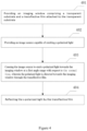
- FIG. 4 is an exemplary flow chart of a displaying method. As shown, the method comprises:
- the s-polarized light has N spectral lines or bands in the visible light band, where N is a positive integer not less than 1, and preferably N is equal to or greater than 3; the FWHM of the spectral lines or bands is less than or equal to 60 nm; wherein within said first angle range, the transflective film has an average reflectivity in the range of 25% to 50% for wavebands within the FWHM of the 3 or more spectral lines or bands of the s-polarized light emitted by the image source, and has an average reflectivity for visible light band outside the FWHM of the N spectral lines or bands of the s-polarized light at least 5% lower than the average reflectivity for the former; and said transflective film has an average transmissivity greater than 60% for p-polarized light in the visible range within said second angle range with respect to the normal line.
- the displaying system of the present invention can be applied in a variety of applications, e.g., to various head-up displays (HUDs) when used together with a base or pedestal; of course, they can also be used in vehicles such as automobiles or aircrafts.
- HUDs head-up displays
- light from the image source and ambient light can be incident to the observer's eyes at the same time to form a clear image, thereby presenting the image of the image source to the observer's eyes without affecting the observer's observation of the external environment.
- s-polarized three-color lights are used as the image source of reflection, and meanwhile an imaging window with s-polarized narrow-band high-reflectivity film is used.
- the spectral bands of the image source and the transflective film are well matched, and since the s-polarized light is not affected by a Brewster's angle, the reflectivity of the light from the image source is greatly improved as compared with the conventional technique, the utilization efficiency of the reflection light is high, and thus the entire optical system can be realized with a lower power consumption.
- the ghost image problem can be well suppressed.
- the observer's perception of the ambient light is almost not affected, since the same optical information can be obtained from the p-polarized ambient light, even if some band of the s-polarized spectrum of the ambient light is filtered.
Landscapes
- Physics & Mathematics (AREA)
- General Physics & Mathematics (AREA)
- Optics & Photonics (AREA)
- Engineering & Computer Science (AREA)
- Chemical & Material Sciences (AREA)
- Combustion & Propulsion (AREA)
- Transportation (AREA)
- Mechanical Engineering (AREA)
- Spectroscopy & Molecular Physics (AREA)
- Polarising Elements (AREA)
- Instrument Panels (AREA)
Claims (16)
- Anzeigesystem, umfassend:ein Abbildungsfenster (2), beinhaltend ein transparentes Substrat und einen transflektiven Film (3), angebracht an einer ersten Fläche des transparenten Substrats; undeine Bildquelle (1), die s-polarisiertes Licht emittiert, das durch den transflektiven Film (3) auf das Abbildungsfenster (2) auftrifft,dadurch gekennzeichnet, dassLicht, das durch die Bildquelle (1) emittiert wurde, bevor es den transflektiven Film (3) erreicht, nur das s-polarisierte Licht aufweist, wobei das durch die Bildquelle (1) emittierte s-polarisierte Licht, bevor es den transflektiven Film (3) erreicht, N Spektrallinien oder -bänder in dem sichtbaren Band aufweist, wobei N eine positive ganze Zahl nicht kleiner als 1 ist;wobei die N Spektrallinien oder -bänder jeweils eine volle Halbwertsbreite bzw. Full-Width-at-Half-Maximum, FWHM, kleiner oder gleich 60 nm aufweisen, und für jede bzw. jedes der N Spektrallinien oder -bänder in dem sichtbaren Spektrum des von der Bildquelle (1) emittierten s-polarisierten Lichts ein Hauptband definiert ist als das Spektralband, das an der Spitze der Linie oder des Bands zentriert ist und sich bis zu der FWHM erstreckt, so dass die N Spektrallinien oder -bänder N Hauptbänder beinhalten;der transflektive Film (3) in der Lage ist zum Reflektieren des von der Bildquelle (1) emittierten s-polarisierten Lichts unter einem ersten Winkel relativ zu der Normalenlinie und auch in der Lage ist zum Transmittieren von Umgebungslicht unter einem zweiten Winkel relativ zu der Normalenlinie, wobei der erste Winkel einen ersten Winkelbereich von 30 bis 89 Grad aufweist und der zweite Winkel einen zweiten Winkelbereich von 30 bis 80 Grad aufweist;wobei der transflektive Film (3) unter dem ersten Winkel eine erste durchschnittliche Reflektivität für das durch die Bildquelle (1) emittierte s-polarisierte Licht in mindestens einem Hauptband der N Hauptbänder aufweist und eine zweite durchschnittliche Reflektivität für das durch die Bildquelle (1) emittierte s-polarisierte Licht in sichtbaren Bändern außerhalb des mindestens einen Hauptbands aufweist, wobei sich die erste durchschnittliche Reflektivität von der zweiten durchschnittlichen Reflektivität unterscheidet,wobei, unter dem ersten Winkel, eine durchschnittliche Reflektivität des transflektiven Films (3) für das durch die Bildquelle (1) emittierte s-polarisierte Licht in jedem der N Hauptbänder größer als 50 % ist; wobei unter dem ersten Winkel eine durchschnittliche s-Polarisation-Reflektivität des transflektiven Films (3) für sichtbare Bänder mindestens 5 % geringer als die für das mindestens eine Hauptband ist;wobei der transflektive Film (3) unter dem zweiten Winkel eine durchschnittliche Transmissivität für p-polarisiertes Licht von größer als 60 % in sowohl dem mindestens einen Hauptband als auch in den sichtbaren Bändern außerhalb des mindestens einen Hauptbands aufweist, wobeider transflektive Film (3) durch Stapeln von mindestens zwei Arten von Filmschichten, die unterschiedliche Brechungsindices aufweisen, gebildet wird, wobei die Zusammensetzung der Filmschicht ausgewählt wird aus einem oder mehreren von Tantalpentoxid, Titanoxid, Magnesiumoxid, Zinkoxid, Zirconiumoxid, Siliciumdioxid, Magnesiumfluorid, Siliciumnitrid, Siliciumoxinitrid und Aluminiumfluorid.
- Anzeigesystem nach Anspruch 1, wobeider transflektive Film (3) einen ersten Anteil des s-polarisierten Lichts unter dem ersten Winkel relativ zu der Normalenlinie als erstes Licht reflektiert,das transparente Substrat ferner eine zweite Fläche, der ersten Fläche gegenüberliegend, aufweist, wobei die zweite Fläche einen zweiten Anteil des s-polarisierten Lichts als zweites Licht reflektiert und einen dritten Anteil des s-polarisierten Lichts als drittes Licht transmittiert und, wobeidas erste Licht, das zweite Licht und das dritte Licht allesamt s-polarisiertes Licht sind.
- Anzeigesystem nach Anspruch 2, wobei ein Antireflexionsfilm (4) auf der zweiten Fläche des transparenten Substrats angeordnet ist, so dass das s-polarisierte Licht nacheinander durch den transflektiven Film (3), das transparente Substrat und den Antireflexionsfilm (4) auf das Abbildungsfenster (2);wobei der Antireflexionsfilm (4) den zweiten Anteil des s-polarisierten Lichts als das zweite Licht reflektiert und den dritten Anteil des s-polarisierten Lichts als das dritte Licht in die Luft transmittiert;wobei der Antireflexionsfilm (4) eine durchschnittliche Transmissivität des Anzeigefensters (2) für sichtbares Licht um 3 % oder mehr erhöht, im Vergleich mit einer Situation, in der der Antireflexionsfilm (4) nicht aufgebracht ist.
- Anzeigesystem nach Anspruch 1, wobei die N Spektrallinien oder -bänder mindestens drei Spektrallinien oder -bänder umfassen, wobei eine Spitzenposition der ersten Spektrallinie oder des ersten Spektralbands im Bereich von 410 nm bis 480 nm liegt, eine Spitzenposition der zweiten Spektrallinie oder des zweiten Spektralbands im Bereich von 500 nm bis 565 nm liegt, und eine Spitzenposition der dritten Spektrallinie oder des dritten Spektralbands im Bereich von 590 nm bis 690 nm liegt.
- Anzeigesystem nach Anspruch 1, wobei der erste Winkelbereich 50 Grad bis 75 Grad beträgt und/oder der zweite Winkelbereich 55 Grad bis 70 Grad beträgt.
- Anzeigesystem nach Anspruch 1, wobei der transflektive Film (3), innerhalb des zweiten Winkelbereichs, eine durchschnittliche Transmissivität größer als 80 % für das p-polarisierte Licht im sichtbaren Bereich aufweist.
- Anzeigesystem nach Anspruch 1, wobei der transflektive Film (3) eine durchschnittliche Reflektivität größer als 70 % für die N Hauptbänder innerhalb des ersten Winkelbereichs aufweist; und der transflektive Film (3) eine durchschnittliche Reflektivität kleiner als 50 % für sichtbares Licht außerhalb der N Hauptbänder aufweist.
- Anzeigesystem nach einem der Ansprüche 1-7, wobei die Bildquelle (1) eine Anzeigevorrichtung ist, die ein virtuelles Bild oder ein reelles Bild, oder ein durch eine solche Anzeigevorrichtung gebildetes virtuelles oder reelles Bild emittiert.
- Anzeigesystem nach einem der Ansprüche 1-7, wobei eine Lichtquelle der Bildquelle (1) einen Laser, eine Leuchtdiode, eine organische Leuchtdiode, ein angeregtes fluoreszierendes Leuchtmaterial, eine Quantenpunktanregungslichtquelle oder irgendeine Kombination davon umfasst.
- Anzeigesystem, umfassend:ein Abbildungsfenster (2), beinhaltend ein transparentes Substrat, das eine erste Fläche und eine zweite Fläche aufweist, und einen transflektiven Film (3), angebracht an der ersten Fläche des transparenten Substrats; undeine Bildquelle (1) zum Emittieren von s-polarisiertem Licht, das durch den transflektiven Film auf das Abbildungsfenster (2) auftrifft,dadurch gekennzeichnet, dassLicht, das durch die Bildquelle (1) emittiert wurde, bevor es den transflektiven Film (3) erreicht, nur das s-polarisierte Licht aufweist, wobei das durch die Bildquelle (1) emittierte s-polarisierte Licht, bevor es den transflektiven Film (3) erreicht, N Spektrallinien oder -bänder in dem sichtbaren Band aufweist, wobei N eine positive ganze Zahl nicht kleiner als 1 ist;wobei die Spektrallinien oder -bänder eine FWHM kleiner oder gleich 60 nm aufweisen, und für jede bzw. jedes der N Spektrallinien oder -bänder in dem sichtbaren Spektrum des von der Bildquelle (1) emittierten s-polarisierten Lichts ein Hauptband definiert ist als das Spektralband, das an der Spitze der Linie oder des Bands zentriert ist und sich bis zu der FWHM erstreckt;der transflektive Film (3) in der Lage ist zum Reflektieren des von der Bildquelle (1) emittierten s-polarisierten Lichts unter einem ersten Winkel relativ zu der Normalenlinie und auch in der Lage ist zum Transmittieren von Umgebungslicht unter einem zweiten Winkel relativ zu der Normalenlinie, wobei der erste Winkel einen ersten Winkelbereich von 30 bis 89 Grad aufweist und der zweite Winkel einen zweiten Winkelbereich von 30 bis 80 Grad aufweist;wobei unter dem ersten Winkel, der transflektive Film (3) eine durchschnittliche Reflektivität im Bereich von 25 % bis 50 % für die N Hauptbänder aufweist; der transflektive Film (3) eine durchschnittliche Reflektivität für sichtbares Licht außerhalb der N Hauptbänder von mindestens 5 % weniger als der durchschnittlichen Reflektivität für die N Hauptbänder aufweist;der transflektive Film (3) eine durchschnittliche Transmissivität größer als 60 % für p-polarisiertes Licht in dem sichtbaren Bereich unter dem zweiten Winkel aufweist; undwobei das Anzeigesystem ferner einen Antireflexionsfilm (4), angebracht an der zweiten Fläche des transparenten Substrats, umfasst, wobei der Antireflexionsfilm (3) die durchschnittliche Transmissivität des Abbildungsfensters (2) für sichtbares Licht um mindestens 3 % erhöht, im Vergleich mit einer Situation, in der der Antireflexionsfilm (4) nicht aufgebracht ist, wobeidas s-polarisierte Licht nacheinander durch den transflektiven Film (3), das transparente Substrat und den Antireflexionsfilm (4) auf das Abbildungsfenster (2), so dass der transflektive Film (3) einen ersten Anteil des s-polarisierten Lichts unter dem ersten Winkel relativ zu der Normalenlinie als erstes Licht reflektiert, wobei der Antireflexionsfilm (4) einen zweiten Anteil des s-polarisierten Lichts als zweites Licht reflektiert und einen dritten Anteil des s-polarisierten Lichts als drittes Licht in die Luft transmittiert, und wobei das erste Licht, das zweite Licht und das dritte Licht allesamt s-polarisiertes Licht sind, und wobeider transflektive Film (3) durch Stapeln von mindestens zwei Arten von Filmschichten, die unterschiedliche Brechungsindices aufweisen, gebildet wird, wobei die Zusammensetzung der Filmschicht ausgewählt wird aus einem oder mehreren von Tantalpentoxid, Titanoxid, Magnesiumoxid, Zinkoxid, Zirconiumoxid, Siliciumdioxid, Magnesiumfluorid, Siliciumnitrid, Siliciumoxinitrid und Aluminiumfluorid.
- Anzeigesystem nach Anspruch 10, wobei die N Spektrallinien oder -bänder mindestens drei Spektrallinien oder -bänder umfassen, wobei eine Spitzenposition der ersten Spektrallinie oder des ersten Spektralbands im Bereich von 410 nm bis 480 nm liegt; eine Spitzenposition der zweiten Spektrallinie oder des zweiten Spektralbands im Bereich von 500 nm bis 565 nm liegt, und eine Spitzenposition der dritten Spektrallinie oder des dritten Spektralbands im Bereich von 590 nm bis 690 nm liegt.
- Anzeigesystem nach Anspruch 10, wobei der erste Winkelbereich 50 Grad bis 75 Grad beträgt und/oder der zweite Winkelbereich 55 Grad bis 70 Grad beträgt.
- Anzeigesystem nach Anspruch 10, wobei der transflektive Film (3), innerhalb des zweiten Winkelbereichs, eine durchschnittliche Transmissivität größer als 80 % für das p-polarisierte Licht im sichtbaren Bereich aufweist.
- Anzeigesystem nach einem der Ansprüche 10-13,
wobei die Bildquelle (1) eine Anzeigevorrichtung ist, die ein virtuelles Bild oder ein reelles Bild, oder ein durch eine solche Anzeigevorrichtung gebildetes virtuelles oder reelles Bild emittiert. - Anzeigesystem nach einem der Ansprüche 10-13, wobei eine Lichtquelle der Bildquelle (1) einen Laser, eine Leuchtdiode, eine organische Leuchtdiode, ein angeregtes fluoreszierendes Leuchtmaterial, eine Quantenpunktanregungslichtquelle oder irgendeine Kombination davon umfasst.
- Fahrzeug, das ein Anzeigesystem nach einem der Ansprüche 1 bis 15 umfasst.
Applications Claiming Priority (3)
| Application Number | Priority Date | Filing Date | Title |
|---|---|---|---|
| CN201610151142 | 2016-03-17 | ||
| CN201610971143.6A CN107203042B (zh) | 2016-03-17 | 2016-11-09 | 显示成像系统及方法、带该系统的交通工具 |
| PCT/CN2017/074181 WO2017157136A1 (zh) | 2016-03-17 | 2017-02-20 | 显示成像系统及方法、带该系统的交通工具 |
Publications (4)
| Publication Number | Publication Date |
|---|---|
| EP3432050A1 EP3432050A1 (de) | 2019-01-23 |
| EP3432050A4 EP3432050A4 (de) | 2019-11-20 |
| EP3432050C0 EP3432050C0 (de) | 2023-12-27 |
| EP3432050B1 true EP3432050B1 (de) | 2023-12-27 |
Family
ID=59904504
Family Applications (1)
| Application Number | Title | Priority Date | Filing Date |
|---|---|---|---|
| EP17765678.2A Active EP3432050B1 (de) | 2016-03-17 | 2017-02-20 | Anzeigeabbildungssystem und -verfahren sowie fahrzeug mit der system |
Country Status (4)
| Country | Link |
|---|---|
| EP (1) | EP3432050B1 (de) |
| JP (1) | JP7315194B2 (de) |
| KR (1) | KR102746159B1 (de) |
| CN (1) | CN107203042B (de) |
Families Citing this family (14)
| Publication number | Priority date | Publication date | Assignee | Title |
|---|---|---|---|---|
| US10684492B2 (en) * | 2016-12-08 | 2020-06-16 | Futurus Technology Co., Ltd. | System for imaging in the air |
| CN108181708B (zh) * | 2018-01-02 | 2020-12-15 | 京东方科技集团股份有限公司 | 一种抬头显示系统及其控制方法 |
| CN111458869A (zh) * | 2019-01-21 | 2020-07-28 | 未来(北京)黑科技有限公司 | 一种反射式透明显示装置及其应用 |
| CN111458870A (zh) * | 2019-01-21 | 2020-07-28 | 未来(北京)黑科技有限公司 | 一种透明显像装置及其应用 |
| CN111458871A (zh) * | 2019-01-21 | 2020-07-28 | 未来(北京)黑科技有限公司 | 一种显像系统及显像方法 |
| CN111458919A (zh) * | 2019-01-21 | 2020-07-28 | 未来(北京)黑科技有限公司 | 一种显示系统及显示方法 |
| CN110045502A (zh) * | 2019-03-23 | 2019-07-23 | 深圳京龙睿信科技有限公司 | 抬头显示器 |
| JP7702966B2 (ja) * | 2020-05-08 | 2025-07-04 | スリーエム イノベイティブ プロパティズ カンパニー | 乗物用ディスプレイシステム |
| CN111766604B (zh) * | 2020-06-09 | 2023-03-03 | 中国电子科技集团公司第十一研究所 | 一种复合测距方法及系统 |
| CN112130325B (zh) * | 2020-09-25 | 2022-07-12 | 东风汽车有限公司 | 车载抬头显示器视差矫正系统、方法、存储介质和电子设备 |
| CN113960795B (zh) | 2021-09-18 | 2023-03-28 | 福耀玻璃工业集团股份有限公司 | 显示车窗及车辆 |
| CN115327779A (zh) * | 2022-09-02 | 2022-11-11 | 深圳市光途显示科技有限公司 | 一种显示装置 |
| CN115527472B (zh) * | 2022-09-23 | 2025-07-04 | 业成光电(深圳)有限公司 | 抬头显示器的鬼影测量方法 |
| WO2024066880A1 (zh) * | 2022-09-26 | 2024-04-04 | 未来(北京)黑科技有限公司 | S偏振光透反膜、挡风窗、显示装置和交通设备 |
Citations (1)
| Publication number | Priority date | Publication date | Assignee | Title |
|---|---|---|---|---|
| JPH11249062A (ja) * | 1998-03-04 | 1999-09-17 | Asahi Glass Co Ltd | 情報表示装置 |
Family Cites Families (16)
| Publication number | Priority date | Publication date | Assignee | Title |
|---|---|---|---|---|
| DE69423651T2 (de) * | 1993-12-21 | 2000-09-21 | Minnesota Mining And Mfg. Co., Saint Paul | Mehrschichtiger optischer film |
| JPH10148787A (ja) * | 1996-11-20 | 1998-06-02 | Central Glass Co Ltd | 表示装置 |
| US6447120B2 (en) * | 1999-07-28 | 2002-09-10 | Moxtex | Image projection system with a polarizing beam splitter |
| WO2003100517A2 (en) * | 2002-05-22 | 2003-12-04 | Chelix Technologies Corp. | Real image configuration for a high efficiency heads-up display (hud) using a polarizing mirror and a polarization preserving screen |
| FR2847988B1 (fr) * | 2002-12-03 | 2005-02-25 | Essilor Int | Separateur de polarisation, procede pour sa fabrication et lentille ophtalmique presentant des inserts de projection le contenant |
| US6952312B2 (en) * | 2002-12-31 | 2005-10-04 | 3M Innovative Properties Company | Head-up display with polarized light source and wide-angle p-polarization reflective polarizer |
| US7158095B2 (en) * | 2003-07-17 | 2007-01-02 | Big Buddy Performance, Inc. | Visual display system for displaying virtual images onto a field of vision |
| US7482996B2 (en) * | 2004-06-28 | 2009-01-27 | Honeywell International Inc. | Head-up display |
| JP5101257B2 (ja) * | 2007-11-26 | 2012-12-19 | 株式会社東芝 | ヘッドアップディスプレイ用光学フィルム、ヘッドアップディスプレイ及び移動体 |
| WO2012042793A1 (ja) * | 2010-10-01 | 2012-04-05 | パナソニック株式会社 | シースルーディスプレイ装置及びシースルーディスプレイ装置を搭載した車両 |
| CN103018796B (zh) * | 2012-10-31 | 2015-02-18 | 南京工业大学 | 一种光学显示用双膜系pc镜片及其制备方法 |
| JP2015025977A (ja) * | 2013-07-26 | 2015-02-05 | 日本精機株式会社 | 走査型投影装置 |
| JP6340807B2 (ja) * | 2014-02-05 | 2018-06-13 | 株式会社リコー | 画像表示装置及び移動体 |
| WO2015142654A1 (en) * | 2014-03-18 | 2015-09-24 | 3M Innovative Properties Company | Low profile image combiner for near-eye displays |
| WO2015177833A1 (ja) | 2014-05-19 | 2015-11-26 | パイオニア株式会社 | 虚像生成素子及びヘッドアップディスプレイ |
| CN105093534A (zh) * | 2015-08-21 | 2015-11-25 | 杨毅 | 显示屏和显示装置 |
-
2016
- 2016-11-09 CN CN201610971143.6A patent/CN107203042B/zh active Active
-
2017
- 2017-02-20 EP EP17765678.2A patent/EP3432050B1/de active Active
- 2017-02-20 KR KR1020187029811A patent/KR102746159B1/ko active Active
- 2017-02-20 JP JP2018568476A patent/JP7315194B2/ja active Active
Patent Citations (1)
| Publication number | Priority date | Publication date | Assignee | Title |
|---|---|---|---|---|
| JPH11249062A (ja) * | 1998-03-04 | 1999-09-17 | Asahi Glass Co Ltd | 情報表示装置 |
Also Published As
| Publication number | Publication date |
|---|---|
| KR20190009278A (ko) | 2019-01-28 |
| JP7315194B2 (ja) | 2023-07-26 |
| JP2019512754A (ja) | 2019-05-16 |
| CN107203042B (zh) | 2021-12-24 |
| EP3432050A1 (de) | 2019-01-23 |
| CN107203042A (zh) | 2017-09-26 |
| EP3432050C0 (de) | 2023-12-27 |
| EP3432050A4 (de) | 2019-11-20 |
| KR102746159B1 (ko) | 2024-12-26 |
Similar Documents
| Publication | Publication Date | Title |
|---|---|---|
| EP3432050A1 (de) | Anzeigeabbildungssystem und -verfahren sowie fahrzeug mit der system | |
| US11397323B2 (en) | Displaying system, method, and vehicle | |
| US6952312B2 (en) | Head-up display with polarized light source and wide-angle p-polarization reflective polarizer | |
| US7320534B2 (en) | Display device | |
| US12403674B2 (en) | Glass laminate including reflective film | |
| CN109219767B (zh) | 平视显示器装置以及冷光镜 | |
| CN106990530B (zh) | 平视显示器装置的冷光镜以及平视显示器装置 | |
| RU2667310C2 (ru) | Устройство визуализации для прозрачных стекол | |
| CN106255917A (zh) | 反射投影型显示装置 | |
| CA2485672A1 (en) | Projection display system | |
| CN114077052A (zh) | 多层图像显示装置、抬头显示器以及交通设备 | |
| WO2018025518A1 (ja) | ヘッドアップディスプレイ装置 | |
| JP2003344801A (ja) | 表示装置 | |
| US20220187603A1 (en) | An optical system | |
| JP2022090496A (ja) | 虚像表示装置、およびコールドミラー | |
| JP4507506B2 (ja) | 画像表示システム | |
| US10663743B2 (en) | Optical wavelength conversion module and illumination module | |
| US20260003186A1 (en) | Windshield glass and head-up display system | |
| CN218824979U (zh) | 抬头显示装置及交通设备 | |
| EP4147088A1 (de) | Anzeigesystem für ein fahrzeug | |
| WO2020244035A1 (zh) | 一种虚像显示装置 | |
| HK1087181A (en) | Head-up display with polarized light source and wide-angle p-polarization reflective polarizer |
Legal Events
| Date | Code | Title | Description |
|---|---|---|---|
| STAA | Information on the status of an ep patent application or granted ep patent |
Free format text: STATUS: THE INTERNATIONAL PUBLICATION HAS BEEN MADE |
|
| PUAI | Public reference made under article 153(3) epc to a published international application that has entered the european phase |
Free format text: ORIGINAL CODE: 0009012 |
|
| STAA | Information on the status of an ep patent application or granted ep patent |
Free format text: STATUS: REQUEST FOR EXAMINATION WAS MADE |
|
| 17P | Request for examination filed |
Effective date: 20180912 |
|
| AK | Designated contracting states |
Kind code of ref document: A1 Designated state(s): AL AT BE BG CH CY CZ DE DK EE ES FI FR GB GR HR HU IE IS IT LI LT LU LV MC MK MT NL NO PL PT RO RS SE SI SK SM TR |
|
| AX | Request for extension of the european patent |
Extension state: BA ME |
|
| DAV | Request for validation of the european patent (deleted) | ||
| DAX | Request for extension of the european patent (deleted) | ||
| RAP1 | Party data changed (applicant data changed or rights of an application transferred) |
Owner name: FUTURUS TECHNOLOGY CO., LTD. |
|
| A4 | Supplementary search report drawn up and despatched |
Effective date: 20191021 |
|
| RIC1 | Information provided on ipc code assigned before grant |
Ipc: G02B 5/30 20060101ALI20191015BHEP Ipc: B60K 35/00 20060101ALI20191015BHEP Ipc: G02B 1/11 20150101ALN20191015BHEP Ipc: G02B 27/01 20060101AFI20191015BHEP |
|
| STAA | Information on the status of an ep patent application or granted ep patent |
Free format text: STATUS: EXAMINATION IS IN PROGRESS |
|
| 17Q | First examination report despatched |
Effective date: 20191220 |
|
| GRAP | Despatch of communication of intention to grant a patent |
Free format text: ORIGINAL CODE: EPIDOSNIGR1 |
|
| STAA | Information on the status of an ep patent application or granted ep patent |
Free format text: STATUS: GRANT OF PATENT IS INTENDED |
|
| RIC1 | Information provided on ipc code assigned before grant |
Ipc: G02B 1/11 20150101ALN20230707BHEP Ipc: G02B 5/30 20060101ALI20230707BHEP Ipc: B60K 35/00 20060101ALI20230707BHEP Ipc: G02B 27/01 20060101AFI20230707BHEP |
|
| INTG | Intention to grant announced |
Effective date: 20230728 |
|
| GRAS | Grant fee paid |
Free format text: ORIGINAL CODE: EPIDOSNIGR3 |
|
| GRAA | (expected) grant |
Free format text: ORIGINAL CODE: 0009210 |
|
| STAA | Information on the status of an ep patent application or granted ep patent |
Free format text: STATUS: THE PATENT HAS BEEN GRANTED |
|
| AK | Designated contracting states |
Kind code of ref document: B1 Designated state(s): AL AT BE BG CH CY CZ DE DK EE ES FI FR GB GR HR HU IE IS IT LI LT LU LV MC MK MT NL NO PL PT RO RS SE SI SK SM TR |
|
| REG | Reference to a national code |
Ref country code: GB Ref legal event code: FG4D |
|
| REG | Reference to a national code |
Ref country code: CH Ref legal event code: EP |
|
| REG | Reference to a national code |
Ref country code: DE Ref legal event code: R096 Ref document number: 602017077925 Country of ref document: DE |
|
| REG | Reference to a national code |
Ref country code: IE Ref legal event code: FG4D |
|
| U01 | Request for unitary effect filed |
Effective date: 20231229 |
|
| U07 | Unitary effect registered |
Designated state(s): AT BE BG DE DK EE FI FR IT LT LU LV MT NL PT SE SI Effective date: 20240112 |
|
| PG25 | Lapsed in a contracting state [announced via postgrant information from national office to epo] |
Ref country code: GR Free format text: LAPSE BECAUSE OF FAILURE TO SUBMIT A TRANSLATION OF THE DESCRIPTION OR TO PAY THE FEE WITHIN THE PRESCRIBED TIME-LIMIT Effective date: 20240328 |
|
| PG25 | Lapsed in a contracting state [announced via postgrant information from national office to epo] |
Ref country code: ES Free format text: LAPSE BECAUSE OF FAILURE TO SUBMIT A TRANSLATION OF THE DESCRIPTION OR TO PAY THE FEE WITHIN THE PRESCRIBED TIME-LIMIT Effective date: 20231227 |
|
| PG25 | Lapsed in a contracting state [announced via postgrant information from national office to epo] |
Ref country code: GR Free format text: LAPSE BECAUSE OF FAILURE TO SUBMIT A TRANSLATION OF THE DESCRIPTION OR TO PAY THE FEE WITHIN THE PRESCRIBED TIME-LIMIT Effective date: 20240328 Ref country code: ES Free format text: LAPSE BECAUSE OF FAILURE TO SUBMIT A TRANSLATION OF THE DESCRIPTION OR TO PAY THE FEE WITHIN THE PRESCRIBED TIME-LIMIT Effective date: 20231227 |
|
| PG25 | Lapsed in a contracting state [announced via postgrant information from national office to epo] |
Ref country code: RS Free format text: LAPSE BECAUSE OF FAILURE TO SUBMIT A TRANSLATION OF THE DESCRIPTION OR TO PAY THE FEE WITHIN THE PRESCRIBED TIME-LIMIT Effective date: 20231227 Ref country code: NO Free format text: LAPSE BECAUSE OF FAILURE TO SUBMIT A TRANSLATION OF THE DESCRIPTION OR TO PAY THE FEE WITHIN THE PRESCRIBED TIME-LIMIT Effective date: 20240327 Ref country code: HR Free format text: LAPSE BECAUSE OF FAILURE TO SUBMIT A TRANSLATION OF THE DESCRIPTION OR TO PAY THE FEE WITHIN THE PRESCRIBED TIME-LIMIT Effective date: 20231227 |
|
| PG25 | Lapsed in a contracting state [announced via postgrant information from national office to epo] |
Ref country code: IS Free format text: LAPSE BECAUSE OF FAILURE TO SUBMIT A TRANSLATION OF THE DESCRIPTION OR TO PAY THE FEE WITHIN THE PRESCRIBED TIME-LIMIT Effective date: 20240427 |
|
| PG25 | Lapsed in a contracting state [announced via postgrant information from national office to epo] |
Ref country code: CZ Free format text: LAPSE BECAUSE OF FAILURE TO SUBMIT A TRANSLATION OF THE DESCRIPTION OR TO PAY THE FEE WITHIN THE PRESCRIBED TIME-LIMIT Effective date: 20231227 |
|
| U21 | Renewal fee for the european patent with unitary effect paid with additional fee |
Year of fee payment: 8 Effective date: 20240619 |
|
| PG25 | Lapsed in a contracting state [announced via postgrant information from national office to epo] |
Ref country code: SK Free format text: LAPSE BECAUSE OF FAILURE TO SUBMIT A TRANSLATION OF THE DESCRIPTION OR TO PAY THE FEE WITHIN THE PRESCRIBED TIME-LIMIT Effective date: 20231227 |
|
| PG25 | Lapsed in a contracting state [announced via postgrant information from national office to epo] |
Ref country code: SM Free format text: LAPSE BECAUSE OF FAILURE TO SUBMIT A TRANSLATION OF THE DESCRIPTION OR TO PAY THE FEE WITHIN THE PRESCRIBED TIME-LIMIT Effective date: 20231227 Ref country code: SK Free format text: LAPSE BECAUSE OF FAILURE TO SUBMIT A TRANSLATION OF THE DESCRIPTION OR TO PAY THE FEE WITHIN THE PRESCRIBED TIME-LIMIT Effective date: 20231227 Ref country code: RO Free format text: LAPSE BECAUSE OF FAILURE TO SUBMIT A TRANSLATION OF THE DESCRIPTION OR TO PAY THE FEE WITHIN THE PRESCRIBED TIME-LIMIT Effective date: 20231227 Ref country code: IS Free format text: LAPSE BECAUSE OF FAILURE TO SUBMIT A TRANSLATION OF THE DESCRIPTION OR TO PAY THE FEE WITHIN THE PRESCRIBED TIME-LIMIT Effective date: 20240427 Ref country code: CZ Free format text: LAPSE BECAUSE OF FAILURE TO SUBMIT A TRANSLATION OF THE DESCRIPTION OR TO PAY THE FEE WITHIN THE PRESCRIBED TIME-LIMIT Effective date: 20231227 |
|
| PG25 | Lapsed in a contracting state [announced via postgrant information from national office to epo] |
Ref country code: PL Free format text: LAPSE BECAUSE OF FAILURE TO SUBMIT A TRANSLATION OF THE DESCRIPTION OR TO PAY THE FEE WITHIN THE PRESCRIBED TIME-LIMIT Effective date: 20231227 |
|
| PG25 | Lapsed in a contracting state [announced via postgrant information from national office to epo] |
Ref country code: PL Free format text: LAPSE BECAUSE OF FAILURE TO SUBMIT A TRANSLATION OF THE DESCRIPTION OR TO PAY THE FEE WITHIN THE PRESCRIBED TIME-LIMIT Effective date: 20231227 |
|
| PG25 | Lapsed in a contracting state [announced via postgrant information from national office to epo] |
Ref country code: MC Free format text: LAPSE BECAUSE OF FAILURE TO SUBMIT A TRANSLATION OF THE DESCRIPTION OR TO PAY THE FEE WITHIN THE PRESCRIBED TIME-LIMIT Effective date: 20231227 |
|
| REG | Reference to a national code |
Ref country code: DE Ref legal event code: R097 Ref document number: 602017077925 Country of ref document: DE Ref country code: CH Ref legal event code: PL |
|
| PG25 | Lapsed in a contracting state [announced via postgrant information from national office to epo] |
Ref country code: CH Free format text: LAPSE BECAUSE OF NON-PAYMENT OF DUE FEES Effective date: 20240229 |
|
| PG25 | Lapsed in a contracting state [announced via postgrant information from national office to epo] |
Ref country code: CH Free format text: LAPSE BECAUSE OF NON-PAYMENT OF DUE FEES Effective date: 20240229 |
|
| PLBE | No opposition filed within time limit |
Free format text: ORIGINAL CODE: 0009261 |
|
| STAA | Information on the status of an ep patent application or granted ep patent |
Free format text: STATUS: NO OPPOSITION FILED WITHIN TIME LIMIT |
|
| 26N | No opposition filed |
Effective date: 20240930 |
|
| PG25 | Lapsed in a contracting state [announced via postgrant information from national office to epo] |
Ref country code: IE Free format text: LAPSE BECAUSE OF NON-PAYMENT OF DUE FEES Effective date: 20240220 |
|
| PG25 | Lapsed in a contracting state [announced via postgrant information from national office to epo] |
Ref country code: IE Free format text: LAPSE BECAUSE OF NON-PAYMENT OF DUE FEES Effective date: 20240220 |
|
| U20 | Renewal fee for the european patent with unitary effect paid |
Year of fee payment: 9 Effective date: 20250107 |
|
| PG25 | Lapsed in a contracting state [announced via postgrant information from national office to epo] |
Ref country code: CY Free format text: LAPSE BECAUSE OF FAILURE TO SUBMIT A TRANSLATION OF THE DESCRIPTION OR TO PAY THE FEE WITHIN THE PRESCRIBED TIME-LIMIT; INVALID AB INITIO Effective date: 20170220 |
|
| PG25 | Lapsed in a contracting state [announced via postgrant information from national office to epo] |
Ref country code: HU Free format text: LAPSE BECAUSE OF FAILURE TO SUBMIT A TRANSLATION OF THE DESCRIPTION OR TO PAY THE FEE WITHIN THE PRESCRIBED TIME-LIMIT; INVALID AB INITIO Effective date: 20170220 |
|
| PG25 | Lapsed in a contracting state [announced via postgrant information from national office to epo] |
Ref country code: TR Free format text: LAPSE BECAUSE OF FAILURE TO SUBMIT A TRANSLATION OF THE DESCRIPTION OR TO PAY THE FEE WITHIN THE PRESCRIBED TIME-LIMIT Effective date: 20231227 |
|
| U20 | Renewal fee for the european patent with unitary effect paid |
Year of fee payment: 10 Effective date: 20260106 |
|
| PGFP | Annual fee paid to national office [announced via postgrant information from national office to epo] |
Ref country code: GB Payment date: 20260106 Year of fee payment: 10 |