EP3431969B1 - Vorrichtung und verfahren zur analyse von fehlern in einem rohrförmigen element - Google Patents
Vorrichtung und verfahren zur analyse von fehlern in einem rohrförmigen element Download PDFInfo
- Publication number
- EP3431969B1 EP3431969B1 EP18183074.6A EP18183074A EP3431969B1 EP 3431969 B1 EP3431969 B1 EP 3431969B1 EP 18183074 A EP18183074 A EP 18183074A EP 3431969 B1 EP3431969 B1 EP 3431969B1
- Authority
- EP
- European Patent Office
- Prior art keywords
- carousel
- tubular member
- frame
- motor
- side sections
- Prior art date
- Legal status (The legal status is an assumption and is not a legal conclusion. Google has not performed a legal analysis and makes no representation as to the accuracy of the status listed.)
- Active
Links
Images


Classifications
-
- G—PHYSICS
- G01—MEASURING; TESTING
- G01N—INVESTIGATING OR ANALYSING MATERIALS BY DETERMINING THEIR CHEMICAL OR PHYSICAL PROPERTIES
- G01N23/00—Investigating or analysing materials by the use of wave or particle radiation, e.g. X-rays or neutrons, not covered by groups G01N3/00 – G01N17/00, G01N21/00 or G01N22/00
- G01N23/02—Investigating or analysing materials by the use of wave or particle radiation, e.g. X-rays or neutrons, not covered by groups G01N3/00 – G01N17/00, G01N21/00 or G01N22/00 by transmitting the radiation through the material
- G01N23/06—Investigating or analysing materials by the use of wave or particle radiation, e.g. X-rays or neutrons, not covered by groups G01N3/00 – G01N17/00, G01N21/00 or G01N22/00 by transmitting the radiation through the material and measuring the absorption
- G01N23/18—Investigating the presence of flaws defects or foreign matter
-
- G—PHYSICS
- G01—MEASURING; TESTING
- G01N—INVESTIGATING OR ANALYSING MATERIALS BY DETERMINING THEIR CHEMICAL OR PHYSICAL PROPERTIES
- G01N23/00—Investigating or analysing materials by the use of wave or particle radiation, e.g. X-rays or neutrons, not covered by groups G01N3/00 – G01N17/00, G01N21/00 or G01N22/00
- G01N23/02—Investigating or analysing materials by the use of wave or particle radiation, e.g. X-rays or neutrons, not covered by groups G01N3/00 – G01N17/00, G01N21/00 or G01N22/00 by transmitting the radiation through the material
- G01N23/04—Investigating or analysing materials by the use of wave or particle radiation, e.g. X-rays or neutrons, not covered by groups G01N3/00 – G01N17/00, G01N21/00 or G01N22/00 by transmitting the radiation through the material and forming images of the material
- G01N23/046—Investigating or analysing materials by the use of wave or particle radiation, e.g. X-rays or neutrons, not covered by groups G01N3/00 – G01N17/00, G01N21/00 or G01N22/00 by transmitting the radiation through the material and forming images of the material using tomography, e.g. computed tomography [CT]
-
- G—PHYSICS
- G01—MEASURING; TESTING
- G01N—INVESTIGATING OR ANALYSING MATERIALS BY DETERMINING THEIR CHEMICAL OR PHYSICAL PROPERTIES
- G01N23/00—Investigating or analysing materials by the use of wave or particle radiation, e.g. X-rays or neutrons, not covered by groups G01N3/00 – G01N17/00, G01N21/00 or G01N22/00
- G01N23/02—Investigating or analysing materials by the use of wave or particle radiation, e.g. X-rays or neutrons, not covered by groups G01N3/00 – G01N17/00, G01N21/00 or G01N22/00 by transmitting the radiation through the material
- G01N23/06—Investigating or analysing materials by the use of wave or particle radiation, e.g. X-rays or neutrons, not covered by groups G01N3/00 – G01N17/00, G01N21/00 or G01N22/00 by transmitting the radiation through the material and measuring the absorption
- G01N23/083—Investigating or analysing materials by the use of wave or particle radiation, e.g. X-rays or neutrons, not covered by groups G01N3/00 – G01N17/00, G01N21/00 or G01N22/00 by transmitting the radiation through the material and measuring the absorption the radiation being X-rays
-
- G—PHYSICS
- G01—MEASURING; TESTING
- G01N—INVESTIGATING OR ANALYSING MATERIALS BY DETERMINING THEIR CHEMICAL OR PHYSICAL PROPERTIES
- G01N2223/00—Investigating materials by wave or particle radiation
- G01N2223/30—Accessories, mechanical or electrical features
- G01N2223/33—Accessories, mechanical or electrical features scanning, i.e. relative motion for measurement of successive object-parts
- G01N2223/3303—Accessories, mechanical or electrical features scanning, i.e. relative motion for measurement of successive object-parts object fixed; source and detector move
-
- G—PHYSICS
- G01—MEASURING; TESTING
- G01N—INVESTIGATING OR ANALYSING MATERIALS BY DETERMINING THEIR CHEMICAL OR PHYSICAL PROPERTIES
- G01N2223/00—Investigating materials by wave or particle radiation
- G01N2223/60—Specific applications or type of materials
- G01N2223/628—Specific applications or type of materials tubes, pipes
-
- G—PHYSICS
- G01—MEASURING; TESTING
- G01N—INVESTIGATING OR ANALYSING MATERIALS BY DETERMINING THEIR CHEMICAL OR PHYSICAL PROPERTIES
- G01N2223/00—Investigating materials by wave or particle radiation
- G01N2223/60—Specific applications or type of materials
- G01N2223/646—Specific applications or type of materials flaws, defects
Definitions
- the present invention relates to the inspection of tubular members to analyze flaws or defects such as cracks or pitting in the tubular member, e.g., a pipeline. More particularly, the present invention relates to a method and apparatus for evaluating flaws in a pipeline after an in-line inspection.
- in-line inspection INFRA
- smart pigging In the case of buried pipelines, it is common to conduct in-line inspection (ILI) by a technology referred to as “smart pigging".
- IPI in-line inspection
- engineers have developed devices called pigs that are sent through buried pipe to perform inspections.
- the pigs are carried through the pipe by the flow of the liquid or gas and can travel or perform inspections over very large distances.
- the pigs carry a small computer to collect, store, and transmit data for analysis.
- Pigs typically use ultrasonics or electro-magnetic acoustics to perform the inspections. In this regard, the measurements from these tools historically have been found to be inaccurate by as much as 50% or more.
- Direct assessment methods used today are Phased Array Ultrasonics, and Manual Ultrasonics testing. These non-destructive methods are capable of detecting the pipe wall anomalies/flaws, however they are incapable of accurately sizing an anomaly/flaw in all three dimensional planes, e.g., length (X), width (Y), and depth (Z). In point of fact, the Z dimension is the most important since it shows how far the flaw extends between the inner and outer surfaces of the pipeline.
- XCT X-ray Computed Tomography
- US 20050041775 A1 and US 3445655 disclose systems for radiographic inspection of tubular bodies or elongated pipes but do not disclose an apparatus where a flat panel X-ray detector is selectively movable.
- the present invention relates to an apparatus for analyzing flaws in a tubular member, particularly a metallic tubular member, as defined in claim 1.
- the present invention relates to a method for analyzing flaws in a structure, in situ, to determine the three-dimensional morphology of a flaw, e.g., a crack, as defined in claim 14.
- Fig. 1 there is shown one arrangement of an x-ray source and a flat panel detector plate in relation to a tubular member to be inspected using the method and inspection apparatus of the present invention.
- the x-ray source S is positioned, in the schematic shown in Fig. 1 , diametrically opposite detector D which emits an x-ray beam which can be a cone beam shown generally as having a centerline C which is focused on the area of interest X on the tubular member T.
- the detector plate D is positioned relative to the tubular member T such that the x-ray cone spread on detector plate D is as large as possible.
- the source S and the detector D are always centered on one another.
- tubular member T may or can be off center to the source S and the detector D, depending upon the O.D. of tubular member T, the source S and detector D remain centered upon one another.
- the source S can be moved or shifted in a right or left direction as viewed with respect to Fig. 1 and as indicated by the arrows P, Q.
- This same freedom of movement in detector D can also be done as shown by the arrows P', Q'.
- the detector would generally be shifted to the left or right, i.e., the center of the detector D would not lie on the diameter of the tubular member.
- the source S can be moved vertically, again with reference to viewing Fig. 1 , such that the source S is further away or closer to the tubular member T thereby spreading or coalescing the spread of the ray cone from the source S on the tubular member T and the detector D.
- the pipe inspection apparatus of the present invention shown generally as 10 comprises first and second, axially spaced, annular frame members shown generally as 12 and 14.
- Frame member 12 has first and second frame segments 16 and 18 while frame member 14 has first and second frame segments 20 and 22.
- a carousel, shown generally as 30, which has first and second axially spaced, annular rims or side sections shown generally as 32 and 34.
- Rim 32 which is connected to frame member 12 has first and second segments 36 and 38 while rim 34 which is connected to frame member 14 has first and second segments 40 and 42.
- Rim segments 36 and 40 are connected together by two spacers/braces, only one of which, spacer 50 is shown.
- segments 38 and 42 are connected together by two spacers or braces, only one of which, spacer 52, is shown.
- a pair of adjustable, releasable toggle clamps 54 and 56 hold rim segments 36 and 38 together.
- clamp 58 hold rim segments 40 and 42 together.
- a plurality of circumferentially spaced threaded grippers 59 which, as shown in this embodiment, are elongated set screws, which are received through threaded throughbores in frame members 12 and 14 and which, as seen, can be selectively adjusted so as to engage and position the frame members 12 and 14 around the outer wall of tubular member T.
- the number, type, and spacing of grippers 59 can be varied, the only proviso being that if it is desired to position inspection apparatus 10 concentrically with respect to tubular member T, there would generally be at least three such grippers 59, preferably spaced approximately 120° apart. It will be understood that any type of gripping or centering assemblies can be used to engage the pipe to be examined.
- Carrier 60 Interconnected to rim segments 38 and 42 is an x-ray source carrier shown generally as 60.
- Carrier 60 is comprised of first and second axially spaced trunnions or mounts 62 and 64 having socket members 62A and 64A, respectively, socket members 62A and 64A rotatably receiving opposite ends of a threaded rod 66.
- a stepper motor 68 Operatively attached to threaded rod 66 is a stepper motor 68, which can rotate rod 66.
- An x-ray source, shown generally as 70 is mounted in a cradle 71.
- Cradle 71 includes a collar 73 which is internally threaded and which receives threaded rod 66 in a rack and pinion type arrangement. Accordingly, it will be appreciated that if stepper motor 68 rotates rod 66, cradle 71 and hence x-ray source 70 will be moved longitudinally along rod 66.
- angle irons 73 and 75 attached to rims 32 and 38 are angle irons 73 and 75, respectively.
- Bolted to trunnions 62 and 64 are plates 63 and 67 which extend under one leg of the angle irons 75 and 73, respectively.
- the cross members 77, 79 form a track or rail on which carrier 71 rides as x-ray source 70 is moved along the length of threaded rod 66. It will be understood that by suitable shimming the x-ray source 70 could be moved further, laterally outwardly from the rims. Further, it will be appreciated that the x-ray source could be suitably mounted so as to be nearer, indeed between the rims.
- Fig. 2 the inspection apparatus of the present invention is shown in its assembled condition.
- respective pairs of the frame segments and the rim segments are generally semicircular and accordingly have surfaces or faces which when apparatus 10 is assembled are in abutting relationship with one another.
- the abutting diametric faces of the rim segment pairs 36, 38 and 40, 42 have overlapping leaf formations (see Fig. 6 ), 76 and 78, which are diametrically opposite leaf formations 80 and 82.
- each of the leaf formations has a series of holes which when the abutting faces of rim segments 36 and 38 are brought together in abutting relationship are in register whereby nut/bolt combinations 84 and 86 can be received in the registering bores to connect the segments 36 and 38.
- a like structure is also present on rim segments 40 and 42.
- each pair of rim segments are also connected by releasable clamps 54 and 56.
- each of the rim segments carrying a hinge assembly shown generally as 90 and 92, the hinge assemblies comprising a bracket 94 secured to rim segment 38 by nut and bolt combinations.
- Bracket 94 extends laterally outwardly from the periphery of rim segment 38 and carries a pivot pin 96.
- An L-shaped hinge member 98 has an elongate slot 100 through which pivot pin 96 is received. As seen in Fig. 2 in the assembled position, one leg of hinge member 98 is secured to rim segment 36 by means of nut and bolt assembly 102.
- frame members 16 and 18 on their diametric abutting faces have registering bores in which are received dowel pins 110 and 112, respectively.
- the dowel pins 110 and 112 assure proper alignment when assembling the apparatus of the present invention in surrounding relationship to a tubular member.
- Figs. 3, 4 , and 5 there are first and second motors 200 and 202 connected by brackets 204 and 205 to frame segments 16 and 20, respectively.
- motor shaft 206 is connected to a spur gear 208.
- Spur gear 208 engages a ring gear 210 which is positioned in an annular recess 212 of frame segment 16.
- axles 214 There are a plurality of circumferentially spaced axles 214 extending through frame segment 16 on which are mounted rollers 216.
- Rim segment 20 is connected to ring gear 210 via a series of circumferentially spaced bolts 220 extending through an annular spacer plate 222, bolts 220 being received in circumferentially spaced threaded bores in ring gear 210.
- a like arrangement appears with respect to the motor 202 and rim segment 42.
- motor 200 rotates shaft 206 and spur gear 208
- the engaged teeth of spur gear 208 and ring gear 210 drive ring gear 210 which rides on rollers 216.
- ring gear 210 is connected to rim segment 38, the result is rotation of rim 32.
- This same construction and method of operation also describes the action of motor 202 and the rotation of rim 34.
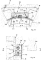
- a worm drive assembly shown generally as 700 is depicted.
- Worm drive assembly 700 comprises a gear box 702 in which is rotatably journaled a worm assembly shown generally as 704.
- Worm 704 comprises a shaft 706, the ends of which are rotatably journaled in bearings 708 and 709.
- a worm screw 710 and beveled gear 712 are mounted on and are rotatable with shaft 706.
- worm wheel 720 Connected to rim 32 by bolts is a worm wheel 720, the teeth of which are engageable with the teeth of worm screw 710.
- a substantially annular shroud 722 overlies worm wheel 720, shroud 722 being connected to gear box 702.
- gear box 702 is connected to frame 16.
- worm wheel 720 is connected to rim segment 38.
- Fig. 14 also depicts how the worm screw 710 is keyed to shaft 706.
- Worm wheel 720 rides on a plurality of circumferentially spaced rollers 740, only one of which is shown in Fig. 14 .
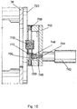
- a motor 742 which as best seen in Fig. 15 drives worm screw 710.
- motor 742 is connected to gear box 702 and has a drive shaft 744 which is connected to the beveled gear shaft 746 of beveled gear 748. It can thus be seen that as motor 742 rotates shaft 746, beveled gear 748 engaged with beveled gear 712 drives shaft 706 and accordingly worm screw 710 which in turn drives worm wheel 720. It will be understood that the worm drive arrangement shown in Figs. 13-15 may be desirable in lieu of the drive assembly shown in Fig. 4 since it has the advantage of transmitting higher torque. However, it is to be understood that any drive assembly can be used to rotate carousel 30. Further, it is to be understood that while the drive system described above, e.g., Figs. 4 and 13-15 , contemplates a drive assembly on each rim, in certain cases only a single drive system on one rim can be used.
- FIGs. 7 and 8 there is shown a connection of a flat panel x-ray detector to the carousel 30 of the present invention.
- Two circumferentially spaced crossbars 300 and 302 are connected at their opposite ends to the spaced rims of carousel 30.
- the bars 300 and 302 have angled slots 304, 306, and 308, 310, respectively.
- Crossbar 300 is connected to laterally spaced posts 312 and 314 while crossbar 302 is connected to laterally spaced posts 316 and 318.
- posts 312, 314, 316, and 318 project through bores which are in open communication with slots 304, 306, 308, and 310.
- the x-ray detector plate 320 will be as close as possible to the outer wall of tubular member T, while at other times it will be at some predetermined distance from the circumference of tubular member T.
- the x-ray detector plate 320 can be selectively positionable relative to tubular member T, not only with respect to its lateral positioning as discussed above with respect to Fig. 1 , but also its radial distance from tubular member T.
- four adjustment bolts, 322, 324, 326, and 328 are received in respective bores to extend through slots 304, 306, 308, and 310, respectively.
- the adjustment bolts 322, 324, 326, and 328 When the adjustment bolts 322, 324, 326, and 328 are loosened, it will be apparent that they will allow the slots to expand slightly whereby the frame 319 connected to the post can move in the directions indicated by arrow A of Fig. 7 . In other words, the flat panel detector can be moved closer or further away from tubular member T. Once positioned in the desired location, the adjustment screws 322, 324, 326, and 328 can then be tightened to hold frame 319 and hence the flat panel x-ray detector in position.
- detector plate 320 it is also preferable for detector plate 320 to be adjustable in the directions of arrow C, i.e., transversely with respect to tubular member T.
- frame 319 has opposed side flanges 321 and 323 in which are formed longitudinally extending slots 325 and 327, respectively. Accordingly, when adjustment bolts 322, 324, 326, 328 are loosened, the posts and hence frame 319 to which the posts are attached, are free to move in the direction of arrow C so as to properly position detector plate 320 with respect to tubular member T.
- Figs. 9 , 10 , and 11 there is shown another embodiment of the invention wherein the grippers used to grab the tubular member T also include driving mechanisms for translating the apparatus 10 along the length of the tubular member T.
- frame segment 400 has a radially outwardly extending, annular flange portion 402, flange portion 402 having an annular, radially outwardly projecting tongue 406.
- An outer ring segment 408 has an annular, radially inwardly extending groove 410 which is complementary to tongue 406.
- ring segment 408 and flange portion 402 are precluded from relative lateral movement.
- ring 408, as seen hereinafter has limited relative rotational freedom relative to flange 402.
- idler roller assembly 420 There are two idler roller assemblies shown generally as 420 and 422, and two driven roller assemblies shown generally as 424 and 426.
- idler roller assembly 420 comprises a roller 430 rotatably carried by an axle 428 mounted in a fork 431.
- Fork 430 has upper and lower ears 432 and 434.
- Pivotally connected to ear 434 is a link 436 which is also pivotally connected to a pin 439 carried by frame segment 400.
- L-shaped link 438 Pivotally connected to ear 432 is a generally L-shaped link 438, link 438 being positioned on a pivot pin 440 anchored in flange portion 402.
- L-shaped link 438 is pivotally connected to a link arm 442 which in turn is pivotally mounted on a pin 444 anchored in ring 408.
- Link 442 is pivotally connected to pin 444 and to L-shaped link 438 by means of the pivot pin 441.
- the grippers/rollers 430 are in gripping engagement with tubular member T.
- a piston cylinder assembly 500 the cylinder 502 being pivotally secured to the flange portion 402 of ring segment 400.
- the piston 504 has a distal end which is pivotally connected to a pivot pin 444.
- outer ring 408 is rotated in the direction of arrow C, the parallelogram type linkage system described above forcing the roller assemblies comprised of forks 431 and rollers 430 into engagement with tubular member T.
- This motor can be seen with respect to arrow E. It will be understood that while the degree of rotation of ring 408 relative to flange 402 is limited it is sufficient to allow the linkage system to force the rollers 430 into gripping engagement with the outer wall of tubular member T.
- roller assemblies 420 and 422 are idler rollers while rollers assemblies 424 and 426 are driven roller assemblies.
- driven roller assembly 424 will be described, it being understood that driven roller assembly 426 is of like construction.
- the driven roller assemblies have the same linkage interconnecting the fork of the roller assemblies and ring 408.
- Mounted on ring segment 400 is a gear motor 560 which has a shaft (not shown) connected to a face gear assembly in a gear box 562, the face gear assembly being in turn connected to shaft 564 which in turn is fixedly connected to roller 566 whereby rotation of motor 560 via the face gear assembly in gear box 562 rotates shaft 564 and hence roller 566.
- the motors 560 when the motors 560 are activated, the driven rollers 566 which are in gripping engagement with the outside wall of tubular member T will translate the inspection apparatus along the length of tubular member T.
- the motors can be battery powered and activated by remote control.
- a schematic flow sheet generally outlining the method of the present invention.
- the apparatus of the present invention is positioned in surrounding relationship to a tubular member, e.g., the pipeline to be inspected. It is significant that with the present invention, in situ inspection of a pipeline can be conducted without the necessity to cut out the section of interest of the pipeline and have it inspected at a remote laboratory site.
- a computer program is used to set a motion control parameter of movement of the carousel around the circumference of the tubular member, the computer program being operable to set motion control parameters based on the size of the tubular member.
- a first two dimensional x-ray image is taken at a first position on the periphery of the tubular member.
- metadata representative of the two dimensional image is collected and stored, steps 604 and 606 being repeated as indicated in step 608 for a full 360° rotation around the tubular member.
- the collected metadata is merged into a single image stack.
- computer software converts the merged two dimensional image stack into a three dimensional image.
- step 614 rendering software or other suitable software generates a three dimensional image of any suspicious areas on the tubular member.
- the computer program isolates specific flaws/anomalies which may be present in the suspicious areas and which deserve further analysis.
- step 618 the computer program sizes the flaws/anomalies to provide X-Y-Z dimensions of the flaws/anomalies.
- step 620 the computer program provides a detailed report of the flaws/anomalies measured including their X-Y-Z morphology. It will be readily apparent that the flaws/anomalies and their morphology/dimensional characteristics can be displayed in real time at the site of the inspection or at a suitable remote location.
Landscapes
- Health & Medical Sciences (AREA)
- General Physics & Mathematics (AREA)
- General Health & Medical Sciences (AREA)
- Pathology (AREA)
- Immunology (AREA)
- Life Sciences & Earth Sciences (AREA)
- Physics & Mathematics (AREA)
- Chemical & Material Sciences (AREA)
- Biochemistry (AREA)
- Analytical Chemistry (AREA)
- Nuclear Medicine, Radiotherapy & Molecular Imaging (AREA)
- Theoretical Computer Science (AREA)
- Engineering & Computer Science (AREA)
- Radiology & Medical Imaging (AREA)
- Pulmonology (AREA)
- Toxicology (AREA)
- Analysing Materials By The Use Of Radiation (AREA)
Claims (14)
- Vorrichtung (10) zur Analyse von Fehlern in einem rohrförmigen Element (T), umfassend:einen Rahmen mit ersten und zweiten axial beabstandeten Seitenteilen (12, 14), wobei jedes der ersten und zweiten Seitenteile (12, 14) erste (16, 20) und zweite Segmente (18, 22) hat, wobei der Rahmen geeignet ist, um ein rohrförmiges Element (T) herum positioniert zu werden; undein Karussell (30), das drehbar auf den Rahmen montiert und geeignet ist, um das rohrförmige Element (T) herum positioniert zu werden, wobei das Karussell (30) dritte und vierte axial beabstandete Seitenteile (32, 34) hat, wobei jeder der dritten und vierten Seitenteile (32, 34) fünfte (36, 40) und sechste Segmente (38, 42) hat;eine auf das Karussell (30) montierte Röntgenquelle (70);einen auf das Karussell (30) in einem Abstand in Umfangsabstand zur Röntgenquelle (70) montierten Flachbild-Röntgenstrahldetektor (D), wobei der Flachbild-Röntgenstrahldetektor (D) bezüglich der dritten und vierten Seitenteile (32, 34) des Karussells (30) selektiv radial nach innen und radial nach außen beweglich ist und/oder wobei der Flachbild-Röntgenstrahldetektor (D) parallel zu den dritten und vierten Seitenteilen (32, 34) des Karussells (30) selektiv in einer zweiten Richtung beweglich ist; undeine Antriebsvorrichtung, die auf den Rahmen montiert ist und mit dem Karussell (30) in Wirkverbindung steht, um das Karussell (30) bezüglich des Rahmens zu drehen.
- Vorrichtung nach Anspruch 1, weiter umfassend:eine erste Vielzahl von am Umfang beabstandeten, selektiv betätigbaren Greifern (59/430) des rohrförmigen Elements, die mit dem ersten Seitenteil (12) des Rahmens verbunden sind; undeine zweite Vielzahl von am Umfang beabstandeten, selektiv betätigbaren Greifern (59/430) des rohrförmigen Elements, die mit dem zweiten Seitenteil (14) des Rahmens verbunden sind.
- Vorrichtung nach Anspruch 1, wobei die fünften (36, 40) und sechsten Segmente (38, 42) jedes der dritten (32) und vierten Seitenteile (34) gelenkig verbunden sind.
- Vorrichtung nach Anspruch 1, wobei der Rahmen und das Karussell (30) ringförmig sind.
- Vorrichtung nach Anspruch 1, wobei der Antrieb einen ersten Motor (200) in Wirkverbindung mit dem dritten Seitenteil (32) des Karussells (30) umfasst.
- Vorrichtung nach Anspruch 5, wobei es einen zweiten Motor (202) in Wirkverbindung mit dem vierten Seitenteil (34) des Karussells (30) gibt.
- Vorrichtung nach Anspruch 5, wobei es ein erstes Rädergetriebe gibt, das den ersten Motor (200) mit dem dritten Seitenteil (32) des Karussells (30) verbindet.
- Vorrichtung nach Anspruch 7, wobei das erste Rädergetriebe ein erstes Stirnrad (208) verbunden mit dem ersten Motor (200) und ein erstes Hohlrad (210) verbunden mit dem dritten Seitenteil (32) des Karussells (30) umfasst.
- Vorrichtung nach Anspruch 7, wobei es ein zweites Rädergetriebe gibt, das den zweiten Motor (202) mit dem vierten Seitenteil (34) des Karussells (30) verbindet.
- Vorrichtung nach Anspruch 9, wobei das zweite Rädergetriebe ein zweites Stirnrad (208) verbunden mit dem zweiten Motor (202) und ein zweites Hohlrad (210) verbunden mit dem vierten Seitenteil (34) des Karussells (30) umfasst.
- Vorrichtung nach Anspruch 7, wobei das erste Rädergetriebe ein erstes Schneckengetriebe (700) umfasst, das eine Schneckenschraube (710) und ein Schneckenrad (720) hat, wobei vorzugsweise erste und zweite Kegelräder (712, 748) die Schneckenschraube (710) des ersten Schneckengetriebes mit dem ersten Motor (200) antriebsmäßig verbinden.
- Vorrichtung nach Anspruch 9, wobei das zweite Rädergetriebe ein zweites Schneckengetriebe (700) umfasst, das eine Schneckenschraube (710) und ein Schneckenrad (720) hat, wobei vorzugsweise dritte und vierte Kegelräder (712, 748) die Schneckenschraube (710) des zweiten Schneckengetriebes (700) mit dem zweiten Motor (202) antriebsmäßig verbinden.
- Vorrichtung nach Anspruch 1, wobei die Röntgenquelle (70) auf einer Achse quer zu den dritten und vierten Seitenteilen (32, 34) des Karussells (30) selektiv beweglich ist.
- Verfahren zur Analyse von Fehlern in einem rohrförmigen Element (T), das eine Wand mit einer inneren Wandfläche und einer äußeren Wandfläche hat, umfassend:1) Positionieren eines Rahmens um die äußere Wand des rohrförmigen Elements (T) herum, wobei der Rahmen ein drehbares Karussell (30) in umgebender Beziehung mit dem rohrförmigen Element (T) enthält;2) Montieren einer Röntgenquelle (70) auf das Karussell (30);3) Montieren eines Flachbild-Röntgenstrahldetektors (D) auf das Karussell (30) in einem Abstand in Umfangsabstand zur Röntgenquelle (70), wobei der Flachbild-Röntgenstrahldetektor (D) bezüglich der dritten und vierten Seitenteile (32, 34) des Karussells (30) selektiv radial nach innen und radial nach außen beweglich ist und/oder wobei der Flachbild-Röntgenstrahldetektor (D) parallel zu den dritten und vierten Seitenteilen (32, 34) des Karussells (30) selektiv in einer zweiten Richtung beweglich ist;4) Aufnehmen eines ersten zweidimensionalen Röntgenbilds in einer ersten Stellung auf dem rohrförmigen Element (T);5) Speichern des ersten Bilds in einer Datenbank;6) Wiederholen der Schritte 4) und 5) in aufeinanderfolgenden Abständen der Drehung des Karussells (30) über einen vorbestimmten Bogen der äußeren Wand des rohrförmigen Elements (T), um eine Vielzahl zweidimensionaler Bilder zu erzeugen, wobei der Bogen mindestens halbkreisförmig ist;7) Zusammenfügen der Vielzahl zweidimensionaler Bilder in einen einzigen zweidimensionalen Bildstapel;8) Umformen des einzigen zweidimensionalen Bildstapels in ein dreidimensionales Bild;9) Analysieren des dreidimensionalen Bilds, um jeden Fehler im rohrförmigen Element einzugrenzen; und10) Berechnen der dreidimensionalen Merkmale des Fehlers.
Applications Claiming Priority (1)
| Application Number | Priority Date | Filing Date | Title |
|---|---|---|---|
| US201762533538P | 2017-07-17 | 2017-07-17 |
Publications (2)
| Publication Number | Publication Date |
|---|---|
| EP3431969A1 EP3431969A1 (de) | 2019-01-23 |
| EP3431969B1 true EP3431969B1 (de) | 2021-09-01 |
Family
ID=62947973
Family Applications (1)
| Application Number | Title | Priority Date | Filing Date |
|---|---|---|---|
| EP18183074.6A Active EP3431969B1 (de) | 2017-07-17 | 2018-07-12 | Vorrichtung und verfahren zur analyse von fehlern in einem rohrförmigen element |
Country Status (5)
| Country | Link |
|---|---|
| US (1) | US10852258B2 (de) |
| EP (1) | EP3431969B1 (de) |
| CA (1) | CA3011066A1 (de) |
| DK (1) | DK3431969T3 (de) |
| ES (1) | ES2890858T3 (de) |
Families Citing this family (4)
| Publication number | Priority date | Publication date | Assignee | Title |
|---|---|---|---|---|
| CN111983176B (zh) * | 2020-08-26 | 2022-09-30 | 浙江双森金属科技股份有限公司 | 一种不锈钢管缺陷检测装置 |
| CN114508651A (zh) * | 2021-12-17 | 2022-05-17 | 安庆精诚石化检测有限公司 | 一种自适应管道探伤承载装置 |
| CN114441569B (zh) * | 2021-12-22 | 2024-06-25 | 江苏至上检测科技有限公司 | 一种焊缝射线检测装置及检测方法 |
| CN117124259A (zh) * | 2023-10-18 | 2023-11-28 | 广西壮族自治区特种设备检验研究院 | 一种压力管道无损检测辅助工具 |
Family Cites Families (15)
| Publication number | Priority date | Publication date | Assignee | Title |
|---|---|---|---|---|
| US3445655A (en) * | 1966-08-18 | 1969-05-20 | Leonard O Curry | Apparatus for the support and movement of radiographic equipment on an elongated pipe |
| DE2044887A1 (de) * | 1969-09-11 | 1971-04-08 | Kurokawa, Toshio, Tokio, Nishiyama, Shoji, Hachinohe, Aomon, Tokyo Shibaura Electric Co , Ltd , Kawasaki, (Japan) | Rontgenaufnahmegerat |
| US3650514A (en) * | 1969-11-07 | 1972-03-21 | Gerald A Stunkard | Self centering pipe working machine |
| US3938492A (en) * | 1973-09-05 | 1976-02-17 | Boyar Schultz Corporation | Over the wheel dresser |
| US3921440A (en) * | 1975-01-02 | 1975-11-25 | Air Prod & Chem | Ultrasonic pipe testing system |
| US4284895A (en) | 1978-02-21 | 1981-08-18 | Ira Lon Morgan | Method and apparatus for tomographic examination of an object by penetrating radiation |
| US5107121A (en) * | 1989-10-27 | 1992-04-21 | Trionix Research Laboratory, Inc. | Gantry and pallet assembly used in nuclear imaging |
| NL9002031A (nl) | 1990-09-14 | 1992-04-01 | Voskuilen Woudenberg Bv | Inrichting voor het bewerken van een uitwendig buisoppervlak. |
| TW439003B (en) | 1995-11-17 | 2001-06-07 | Semiconductor Energy Lab | Display device |
| US6272200B1 (en) * | 1999-07-28 | 2001-08-07 | Arch Development Corporation | Fourier and spline-based reconstruction of helical CT images |
| US6925145B2 (en) * | 2003-08-22 | 2005-08-02 | General Electric Company | High speed digital radiographic inspection of piping |
| US7003070B1 (en) * | 2004-08-03 | 2006-02-21 | William Barry Chen | Upright CT scanner |
| KR100687846B1 (ko) * | 2005-01-21 | 2007-02-27 | 경희대학교 산학협력단 | 국부 고해상도 엑스선 단층 영상 재구성 방법 및 국부고해상도 엑스선 단층 영상 재구성 장치 |
| US8141442B2 (en) | 2009-05-04 | 2012-03-27 | Westinghouse Electric Company Llc | Pipe scanner |
| CN103476340B (zh) * | 2010-11-27 | 2017-02-15 | 艾赛克有限公司 | 计算机断层摄影和断层合成系统 |
-
2018
- 2018-07-06 US US16/029,210 patent/US10852258B2/en active Active
- 2018-07-11 CA CA3011066A patent/CA3011066A1/en active Pending
- 2018-07-12 EP EP18183074.6A patent/EP3431969B1/de active Active
- 2018-07-12 DK DK18183074.6T patent/DK3431969T3/da active
- 2018-07-12 ES ES18183074T patent/ES2890858T3/es active Active
Also Published As
| Publication number | Publication date |
|---|---|
| DK3431969T3 (da) | 2021-11-22 |
| US20190017944A1 (en) | 2019-01-17 |
| EP3431969A1 (de) | 2019-01-23 |
| CA3011066A1 (en) | 2019-01-17 |
| US10852258B2 (en) | 2020-12-01 |
| ES2890858T3 (es) | 2022-01-24 |
Similar Documents
| Publication | Publication Date | Title |
|---|---|---|
| EP3431969B1 (de) | Vorrichtung und verfahren zur analyse von fehlern in einem rohrförmigen element | |
| US4718277A (en) | Method and apparatus for characterizing defects in tubular members | |
| US6925145B2 (en) | High speed digital radiographic inspection of piping | |
| US8723943B2 (en) | Pipeline inspection system | |
| US8061208B2 (en) | Non-destructive pipe scanner | |
| US8301401B2 (en) | Low profile encircling ultrasonic probe for the inspection of in-situ piping in immersion mode | |
| US8215174B2 (en) | Inspection apparatus for tubular members | |
| US5600069A (en) | Ultrasonic testing apparatus and method for multiple diameter oilfield tubulars | |
| CN108180346A (zh) | 一种管道巡视机器人 | |
| KR101530337B1 (ko) | 압력용기 카테고리 용접부 전용 자동 위상배열 초음파 검사장치 | |
| CN208255098U (zh) | 一种用于不同直径管道环焊缝x射线检测的装置 | |
| EP2270487B2 (de) | Vorrichtung zur Ultraschallprüfung von Radsatzwellen von Eisenbahn-Güterwagen im eingebauten Zustand | |
| CN217332273U (zh) | 一种管道无损检测装置 | |
| Komori et al. | Inspection robots for gas pipelines of Tokyo Gas | |
| CN104979027A (zh) | 核电站控制棒驱动组件下部ω焊缝涡流扫查器 | |
| An et al. | Tube inner wall defect detection method based on rotary scanning micro laser distance sensor | |
| CN110967400A (zh) | 大型储罐底板缺陷的兰姆波层析成像方法 | |
| CN117825634A (zh) | 一种管道内壁无损检测装置 | |
| CN207751906U (zh) | 一种放射源现场防护屏蔽装置 | |
| RU75750U1 (ru) | Автономный магнитный дефектоскоп наружного контроля трубопроводов | |
| Wang et al. | Development of new pipeline maintenance system for repairing early-built offshore oil pipelines | |
| CN110018242B (zh) | 一种用于横向裂纹的自动扫查装置 | |
| RU2692868C1 (ru) | Носитель датчиков дефектоскопа внутритрубного ультразвукового | |
| CN219389417U (zh) | 在线管道扫描建模及壁厚监测设备 | |
| JP3045570B2 (ja) | 管内超音波自動探傷装置 |
Legal Events
| Date | Code | Title | Description |
|---|---|---|---|
| PUAI | Public reference made under article 153(3) epc to a published international application that has entered the european phase |
Free format text: ORIGINAL CODE: 0009012 |
|
| STAA | Information on the status of an ep patent application or granted ep patent |
Free format text: STATUS: THE APPLICATION HAS BEEN PUBLISHED |
|
| AK | Designated contracting states |
Kind code of ref document: A1 Designated state(s): AL AT BE BG CH CY CZ DE DK EE ES FI FR GB GR HR HU IE IS IT LI LT LU LV MC MK MT NL NO PL PT RO RS SE SI SK SM TR |
|
| AX | Request for extension of the european patent |
Extension state: BA ME |
|
| STAA | Information on the status of an ep patent application or granted ep patent |
Free format text: STATUS: REQUEST FOR EXAMINATION WAS MADE |
|
| 17P | Request for examination filed |
Effective date: 20190723 |
|
| RBV | Designated contracting states (corrected) |
Designated state(s): AL AT BE BG CH CY CZ DE DK EE ES FI FR GB GR HR HU IE IS IT LI LT LU LV MC MK MT NL NO PL PT RO RS SE SI SK SM TR |
|
| GRAP | Despatch of communication of intention to grant a patent |
Free format text: ORIGINAL CODE: EPIDOSNIGR1 |
|
| STAA | Information on the status of an ep patent application or granted ep patent |
Free format text: STATUS: GRANT OF PATENT IS INTENDED |
|
| INTG | Intention to grant announced |
Effective date: 20210518 |
|
| GRAS | Grant fee paid |
Free format text: ORIGINAL CODE: EPIDOSNIGR3 |
|
| GRAA | (expected) grant |
Free format text: ORIGINAL CODE: 0009210 |
|
| STAA | Information on the status of an ep patent application or granted ep patent |
Free format text: STATUS: THE PATENT HAS BEEN GRANTED |
|
| AK | Designated contracting states |
Kind code of ref document: B1 Designated state(s): AL AT BE BG CH CY CZ DE DK EE ES FI FR GB GR HR HU IE IS IT LI LT LU LV MC MK MT NL NO PL PT RO RS SE SI SK SM TR |
|
| REG | Reference to a national code |
Ref country code: GB Ref legal event code: FG4D |
|
| REG | Reference to a national code |
Ref country code: CH Ref legal event code: EP Ref country code: AT Ref legal event code: REF Ref document number: 1426731 Country of ref document: AT Kind code of ref document: T Effective date: 20210915 |
|
| REG | Reference to a national code |
Ref country code: DE Ref legal event code: R096 Ref document number: 602018022692 Country of ref document: DE |
|
| REG | Reference to a national code |
Ref country code: IE Ref legal event code: FG4D |
|
| REG | Reference to a national code |
Ref country code: NL Ref legal event code: FP |
|
| REG | Reference to a national code |
Ref country code: DK Ref legal event code: T3 Effective date: 20211116 |
|
| REG | Reference to a national code |
Ref country code: SE Ref legal event code: TRGR |
|
| REG | Reference to a national code |
Ref country code: LT Ref legal event code: MG9D |
|
| REG | Reference to a national code |
Ref country code: NO Ref legal event code: T2 Effective date: 20210901 |
|
| REG | Reference to a national code |
Ref country code: ES Ref legal event code: FG2A Ref document number: 2890858 Country of ref document: ES Kind code of ref document: T3 Effective date: 20220124 |
|
| PG25 | Lapsed in a contracting state [announced via postgrant information from national office to epo] |
Ref country code: LT Free format text: LAPSE BECAUSE OF FAILURE TO SUBMIT A TRANSLATION OF THE DESCRIPTION OR TO PAY THE FEE WITHIN THE PRESCRIBED TIME-LIMIT Effective date: 20210901 Ref country code: BG Free format text: LAPSE BECAUSE OF FAILURE TO SUBMIT A TRANSLATION OF THE DESCRIPTION OR TO PAY THE FEE WITHIN THE PRESCRIBED TIME-LIMIT Effective date: 20211201 Ref country code: RS Free format text: LAPSE BECAUSE OF FAILURE TO SUBMIT A TRANSLATION OF THE DESCRIPTION OR TO PAY THE FEE WITHIN THE PRESCRIBED TIME-LIMIT Effective date: 20210901 Ref country code: HR Free format text: LAPSE BECAUSE OF FAILURE TO SUBMIT A TRANSLATION OF THE DESCRIPTION OR TO PAY THE FEE WITHIN THE PRESCRIBED TIME-LIMIT Effective date: 20210901 Ref country code: FI Free format text: LAPSE BECAUSE OF FAILURE TO SUBMIT A TRANSLATION OF THE DESCRIPTION OR TO PAY THE FEE WITHIN THE PRESCRIBED TIME-LIMIT Effective date: 20210901 |
|
| REG | Reference to a national code |
Ref country code: AT Ref legal event code: MK05 Ref document number: 1426731 Country of ref document: AT Kind code of ref document: T Effective date: 20210901 |
|
| PG25 | Lapsed in a contracting state [announced via postgrant information from national office to epo] |
Ref country code: PL Free format text: LAPSE BECAUSE OF FAILURE TO SUBMIT A TRANSLATION OF THE DESCRIPTION OR TO PAY THE FEE WITHIN THE PRESCRIBED TIME-LIMIT Effective date: 20210901 Ref country code: LV Free format text: LAPSE BECAUSE OF FAILURE TO SUBMIT A TRANSLATION OF THE DESCRIPTION OR TO PAY THE FEE WITHIN THE PRESCRIBED TIME-LIMIT Effective date: 20210901 Ref country code: GR Free format text: LAPSE BECAUSE OF FAILURE TO SUBMIT A TRANSLATION OF THE DESCRIPTION OR TO PAY THE FEE WITHIN THE PRESCRIBED TIME-LIMIT Effective date: 20211202 |
|
| PG25 | Lapsed in a contracting state [announced via postgrant information from national office to epo] |
Ref country code: AT Free format text: LAPSE BECAUSE OF FAILURE TO SUBMIT A TRANSLATION OF THE DESCRIPTION OR TO PAY THE FEE WITHIN THE PRESCRIBED TIME-LIMIT Effective date: 20210901 |
|
| PG25 | Lapsed in a contracting state [announced via postgrant information from national office to epo] |
Ref country code: IS Free format text: LAPSE BECAUSE OF FAILURE TO SUBMIT A TRANSLATION OF THE DESCRIPTION OR TO PAY THE FEE WITHIN THE PRESCRIBED TIME-LIMIT Effective date: 20220101 Ref country code: SM Free format text: LAPSE BECAUSE OF FAILURE TO SUBMIT A TRANSLATION OF THE DESCRIPTION OR TO PAY THE FEE WITHIN THE PRESCRIBED TIME-LIMIT Effective date: 20210901 Ref country code: SK Free format text: LAPSE BECAUSE OF FAILURE TO SUBMIT A TRANSLATION OF THE DESCRIPTION OR TO PAY THE FEE WITHIN THE PRESCRIBED TIME-LIMIT Effective date: 20210901 Ref country code: RO Free format text: LAPSE BECAUSE OF FAILURE TO SUBMIT A TRANSLATION OF THE DESCRIPTION OR TO PAY THE FEE WITHIN THE PRESCRIBED TIME-LIMIT Effective date: 20210901 Ref country code: PT Free format text: LAPSE BECAUSE OF FAILURE TO SUBMIT A TRANSLATION OF THE DESCRIPTION OR TO PAY THE FEE WITHIN THE PRESCRIBED TIME-LIMIT Effective date: 20220103 Ref country code: EE Free format text: LAPSE BECAUSE OF FAILURE TO SUBMIT A TRANSLATION OF THE DESCRIPTION OR TO PAY THE FEE WITHIN THE PRESCRIBED TIME-LIMIT Effective date: 20210901 Ref country code: CZ Free format text: LAPSE BECAUSE OF FAILURE TO SUBMIT A TRANSLATION OF THE DESCRIPTION OR TO PAY THE FEE WITHIN THE PRESCRIBED TIME-LIMIT Effective date: 20210901 Ref country code: AL Free format text: LAPSE BECAUSE OF FAILURE TO SUBMIT A TRANSLATION OF THE DESCRIPTION OR TO PAY THE FEE WITHIN THE PRESCRIBED TIME-LIMIT Effective date: 20210901 |
|
| REG | Reference to a national code |
Ref country code: DE Ref legal event code: R097 Ref document number: 602018022692 Country of ref document: DE |
|
| PLBE | No opposition filed within time limit |
Free format text: ORIGINAL CODE: 0009261 |
|
| STAA | Information on the status of an ep patent application or granted ep patent |
Free format text: STATUS: NO OPPOSITION FILED WITHIN TIME LIMIT |
|
| 26N | No opposition filed |
Effective date: 20220602 |
|
| PG25 | Lapsed in a contracting state [announced via postgrant information from national office to epo] |
Ref country code: SI Free format text: LAPSE BECAUSE OF FAILURE TO SUBMIT A TRANSLATION OF THE DESCRIPTION OR TO PAY THE FEE WITHIN THE PRESCRIBED TIME-LIMIT Effective date: 20210901 |
|
| PG25 | Lapsed in a contracting state [announced via postgrant information from national office to epo] |
Ref country code: MC Free format text: LAPSE BECAUSE OF FAILURE TO SUBMIT A TRANSLATION OF THE DESCRIPTION OR TO PAY THE FEE WITHIN THE PRESCRIBED TIME-LIMIT Effective date: 20210901 |
|
| PG25 | Lapsed in a contracting state [announced via postgrant information from national office to epo] |
Ref country code: LU Free format text: LAPSE BECAUSE OF NON-PAYMENT OF DUE FEES Effective date: 20220712 |
|
| P01 | Opt-out of the competence of the unified patent court (upc) registered |
Effective date: 20230516 |
|
| PG25 | Lapsed in a contracting state [announced via postgrant information from national office to epo] |
Ref country code: IE Free format text: LAPSE BECAUSE OF NON-PAYMENT OF DUE FEES Effective date: 20220712 |
|
| PG25 | Lapsed in a contracting state [announced via postgrant information from national office to epo] |
Ref country code: HU Free format text: LAPSE BECAUSE OF FAILURE TO SUBMIT A TRANSLATION OF THE DESCRIPTION OR TO PAY THE FEE WITHIN THE PRESCRIBED TIME-LIMIT; INVALID AB INITIO Effective date: 20180712 |
|
| PG25 | Lapsed in a contracting state [announced via postgrant information from national office to epo] |
Ref country code: MK Free format text: LAPSE BECAUSE OF FAILURE TO SUBMIT A TRANSLATION OF THE DESCRIPTION OR TO PAY THE FEE WITHIN THE PRESCRIBED TIME-LIMIT Effective date: 20210901 Ref country code: CY Free format text: LAPSE BECAUSE OF FAILURE TO SUBMIT A TRANSLATION OF THE DESCRIPTION OR TO PAY THE FEE WITHIN THE PRESCRIBED TIME-LIMIT Effective date: 20210901 |
|
| PG25 | Lapsed in a contracting state [announced via postgrant information from national office to epo] |
Ref country code: TR Free format text: LAPSE BECAUSE OF FAILURE TO SUBMIT A TRANSLATION OF THE DESCRIPTION OR TO PAY THE FEE WITHIN THE PRESCRIBED TIME-LIMIT Effective date: 20210901 |
|
| PGFP | Annual fee paid to national office [announced via postgrant information from national office to epo] |
Ref country code: NL Payment date: 20240726 Year of fee payment: 7 |
|
| PG25 | Lapsed in a contracting state [announced via postgrant information from national office to epo] |
Ref country code: MT Free format text: LAPSE BECAUSE OF FAILURE TO SUBMIT A TRANSLATION OF THE DESCRIPTION OR TO PAY THE FEE WITHIN THE PRESCRIBED TIME-LIMIT Effective date: 20210901 |
|
| PGFP | Annual fee paid to national office [announced via postgrant information from national office to epo] |
Ref country code: DK Payment date: 20240725 Year of fee payment: 7 |
|
| PGFP | Annual fee paid to national office [announced via postgrant information from national office to epo] |
Ref country code: BE Payment date: 20240729 Year of fee payment: 7 |
|
| PGFP | Annual fee paid to national office [announced via postgrant information from national office to epo] |
Ref country code: FR Payment date: 20240725 Year of fee payment: 7 |
|
| PGFP | Annual fee paid to national office [announced via postgrant information from national office to epo] |
Ref country code: CH Payment date: 20240801 Year of fee payment: 7 Ref country code: ES Payment date: 20240801 Year of fee payment: 7 |
|
| PGFP | Annual fee paid to national office [announced via postgrant information from national office to epo] |
Ref country code: NO Payment date: 20240729 Year of fee payment: 7 Ref country code: SE Payment date: 20240727 Year of fee payment: 7 Ref country code: IT Payment date: 20240719 Year of fee payment: 7 |
|
| PGFP | Annual fee paid to national office [announced via postgrant information from national office to epo] |
Ref country code: DE Payment date: 20250729 Year of fee payment: 8 |
|
| PGFP | Annual fee paid to national office [announced via postgrant information from national office to epo] |
Ref country code: GB Payment date: 20250728 Year of fee payment: 8 |
|
| REG | Reference to a national code |
Ref country code: DK Ref legal event code: EBP Effective date: 20250731 |
|
| REG | Reference to a national code |
Ref country code: CH Ref legal event code: H13 Free format text: ST27 STATUS EVENT CODE: U-0-0-H10-H13 (AS PROVIDED BY THE NATIONAL OFFICE) Effective date: 20260224 |
|
| REG | Reference to a national code |
Ref country code: NL Ref legal event code: MM Effective date: 20250801 |
|
| REG | Reference to a national code |
Ref country code: BE Ref legal event code: MM Effective date: 20250731 |
|
| PG25 | Lapsed in a contracting state [announced via postgrant information from national office to epo] |
Ref country code: NO Free format text: LAPSE BECAUSE OF NON-PAYMENT OF DUE FEES Effective date: 20250731 |
|
| PG25 | Lapsed in a contracting state [announced via postgrant information from national office to epo] |
Ref country code: BE Free format text: LAPSE BECAUSE OF NON-PAYMENT OF DUE FEES Effective date: 20250731 |
|
| PG25 | Lapsed in a contracting state [announced via postgrant information from national office to epo] |
Ref country code: NL Free format text: LAPSE BECAUSE OF NON-PAYMENT OF DUE FEES Effective date: 20250801 |
|
| PG25 | Lapsed in a contracting state [announced via postgrant information from national office to epo] |
Ref country code: FR Free format text: LAPSE BECAUSE OF NON-PAYMENT OF DUE FEES Effective date: 20250731 |
|
| PG25 | Lapsed in a contracting state [announced via postgrant information from national office to epo] |
Ref country code: CH Free format text: LAPSE BECAUSE OF NON-PAYMENT OF DUE FEES Effective date: 20250731 |