EP3431913B1 - Erwärmungsvorrichtung für fluide in einem kfz - Google Patents
Erwärmungsvorrichtung für fluide in einem kfz Download PDFInfo
- Publication number
- EP3431913B1 EP3431913B1 EP18183596.8A EP18183596A EP3431913B1 EP 3431913 B1 EP3431913 B1 EP 3431913B1 EP 18183596 A EP18183596 A EP 18183596A EP 3431913 B1 EP3431913 B1 EP 3431913B1
- Authority
- EP
- European Patent Office
- Prior art keywords
- heating device
- housing
- heat exchanger
- base plate
- pins
- Prior art date
- Legal status (The legal status is an assumption and is not a legal conclusion. Google has not performed a legal analysis and makes no representation as to the accuracy of the status listed.)
- Active
Links
Images


Classifications
-
- F—MECHANICAL ENGINEERING; LIGHTING; HEATING; WEAPONS; BLASTING
- F28—HEAT EXCHANGE IN GENERAL
- F28D—HEAT-EXCHANGE APPARATUS, NOT PROVIDED FOR IN ANOTHER SUBCLASS, IN WHICH THE HEAT-EXCHANGE MEDIA DO NOT COME INTO DIRECT CONTACT
- F28D9/00—Heat-exchange apparatus having stationary plate-like or laminated conduit assemblies for both heat-exchange media, the media being in contact with different sides of a conduit wall
- F28D9/0031—Heat-exchange apparatus having stationary plate-like or laminated conduit assemblies for both heat-exchange media, the media being in contact with different sides of a conduit wall the conduits for one heat-exchange medium being formed by paired plates touching each other
- F28D9/0037—Heat-exchange apparatus having stationary plate-like or laminated conduit assemblies for both heat-exchange media, the media being in contact with different sides of a conduit wall the conduits for one heat-exchange medium being formed by paired plates touching each other the conduits for the other heat-exchange medium also being formed by paired plates touching each other
-
- F—MECHANICAL ENGINEERING; LIGHTING; HEATING; WEAPONS; BLASTING
- F01—MACHINES OR ENGINES IN GENERAL; ENGINE PLANTS IN GENERAL; STEAM ENGINES
- F01N—GAS-FLOW SILENCERS OR EXHAUST APPARATUS FOR MACHINES OR ENGINES IN GENERAL; GAS-FLOW SILENCERS OR EXHAUST APPARATUS FOR INTERNAL-COMBUSTION ENGINES
- F01N13/00—Exhaust or silencing apparatus characterised by constructional features
- F01N13/18—Construction facilitating manufacture, assembly, or disassembly
- F01N13/1888—Construction facilitating manufacture, assembly, or disassembly the housing of the assembly consisting of two or more parts, e.g. two half-shells
-
- F—MECHANICAL ENGINEERING; LIGHTING; HEATING; WEAPONS; BLASTING
- F01—MACHINES OR ENGINES IN GENERAL; ENGINE PLANTS IN GENERAL; STEAM ENGINES
- F01N—GAS-FLOW SILENCERS OR EXHAUST APPARATUS FOR MACHINES OR ENGINES IN GENERAL; GAS-FLOW SILENCERS OR EXHAUST APPARATUS FOR INTERNAL-COMBUSTION ENGINES
- F01N3/00—Exhaust or silencing apparatus having means for purifying, rendering innocuous, or otherwise treating exhaust
- F01N3/08—Exhaust or silencing apparatus having means for purifying, rendering innocuous, or otherwise treating exhaust for rendering innocuous
- F01N3/10—Exhaust or silencing apparatus having means for purifying, rendering innocuous, or otherwise treating exhaust for rendering innocuous by thermal or catalytic conversion of noxious components of exhaust
- F01N3/18—Exhaust or silencing apparatus having means for purifying, rendering innocuous, or otherwise treating exhaust for rendering innocuous by thermal or catalytic conversion of noxious components of exhaust characterised by methods of operation; Control
- F01N3/20—Exhaust or silencing apparatus having means for purifying, rendering innocuous, or otherwise treating exhaust for rendering innocuous by thermal or catalytic conversion of noxious components of exhaust characterised by methods of operation; Control specially adapted for catalytic conversion
- F01N3/206—Adding periodically or continuously substances to exhaust gases for promoting purification, e.g. catalytic material in liquid form, NOx reducing agents
- F01N3/2066—Selective catalytic reduction [SCR]
-
- F—MECHANICAL ENGINEERING; LIGHTING; HEATING; WEAPONS; BLASTING
- F02—COMBUSTION ENGINES; HOT-GAS OR COMBUSTION-PRODUCT ENGINE PLANTS
- F02M—SUPPLYING COMBUSTION ENGINES IN GENERAL WITH COMBUSTIBLE MIXTURES OR CONSTITUENTS THEREOF
- F02M25/00—Engine-pertinent apparatus for adding non-fuel substances or small quantities of secondary fuel to combustion-air, main fuel or fuel-air mixture
- F02M25/022—Adding fuel and water emulsion, water or steam
- F02M25/0221—Details of the water supply system, e.g. pumps or arrangement of valves
-
- F—MECHANICAL ENGINEERING; LIGHTING; HEATING; WEAPONS; BLASTING
- F24—HEATING; RANGES; VENTILATING
- F24H—FLUID HEATERS, e.g. WATER OR AIR HEATERS, HAVING HEAT-GENERATING MEANS, e.g. HEAT PUMPS, IN GENERAL
- F24H1/00—Water heaters, e.g. boilers, continuous-flow heaters or water-storage heaters
- F24H1/10—Continuous-flow heaters, i.e. heaters in which heat is generated only while the water is flowing, e.g. with direct contact of the water with the heating medium
- F24H1/12—Continuous-flow heaters, i.e. heaters in which heat is generated only while the water is flowing, e.g. with direct contact of the water with the heating medium in which the water is kept separate from the heating medium
- F24H1/121—Continuous-flow heaters, i.e. heaters in which heat is generated only while the water is flowing, e.g. with direct contact of the water with the heating medium in which the water is kept separate from the heating medium using electric energy supply
-
- F—MECHANICAL ENGINEERING; LIGHTING; HEATING; WEAPONS; BLASTING
- F28—HEAT EXCHANGE IN GENERAL
- F28F—DETAILS OF HEAT-EXCHANGE AND HEAT-TRANSFER APPARATUS, OF GENERAL APPLICATION
- F28F3/00—Plate-like or laminated elements; Assemblies of plate-like or laminated elements
- F28F3/02—Elements or assemblies thereof with means for increasing heat-transfer area, e.g. with fins, with recesses, with corrugations
- F28F3/022—Elements or assemblies thereof with means for increasing heat-transfer area, e.g. with fins, with recesses, with corrugations the means being wires or pins
-
- F—MECHANICAL ENGINEERING; LIGHTING; HEATING; WEAPONS; BLASTING
- F28—HEAT EXCHANGE IN GENERAL
- F28F—DETAILS OF HEAT-EXCHANGE AND HEAT-TRANSFER APPARATUS, OF GENERAL APPLICATION
- F28F9/00—Casings; Header boxes; Auxiliary supports for elements; Auxiliary members within casings
- F28F9/001—Casings in the form of plate-like arrangements; Frames enclosing a heat exchange core
-
- F—MECHANICAL ENGINEERING; LIGHTING; HEATING; WEAPONS; BLASTING
- F01—MACHINES OR ENGINES IN GENERAL; ENGINE PLANTS IN GENERAL; STEAM ENGINES
- F01N—GAS-FLOW SILENCERS OR EXHAUST APPARATUS FOR MACHINES OR ENGINES IN GENERAL; GAS-FLOW SILENCERS OR EXHAUST APPARATUS FOR INTERNAL-COMBUSTION ENGINES
- F01N2240/00—Combination or association of two or more different exhaust treating devices, or of at least one such device with an auxiliary device, not covered by indexing codes F01N2230/00 or F01N2250/00, one of the devices being
- F01N2240/02—Combination or association of two or more different exhaust treating devices, or of at least one such device with an auxiliary device, not covered by indexing codes F01N2230/00 or F01N2250/00, one of the devices being a heat exchanger
-
- F—MECHANICAL ENGINEERING; LIGHTING; HEATING; WEAPONS; BLASTING
- F01—MACHINES OR ENGINES IN GENERAL; ENGINE PLANTS IN GENERAL; STEAM ENGINES
- F01N—GAS-FLOW SILENCERS OR EXHAUST APPARATUS FOR MACHINES OR ENGINES IN GENERAL; GAS-FLOW SILENCERS OR EXHAUST APPARATUS FOR INTERNAL-COMBUSTION ENGINES
- F01N2240/00—Combination or association of two or more different exhaust treating devices, or of at least one such device with an auxiliary device, not covered by indexing codes F01N2230/00 or F01N2250/00, one of the devices being
- F01N2240/16—Combination or association of two or more different exhaust treating devices, or of at least one such device with an auxiliary device, not covered by indexing codes F01N2230/00 or F01N2250/00, one of the devices being an electric heater, i.e. a resistance heater
-
- F—MECHANICAL ENGINEERING; LIGHTING; HEATING; WEAPONS; BLASTING
- F01—MACHINES OR ENGINES IN GENERAL; ENGINE PLANTS IN GENERAL; STEAM ENGINES
- F01N—GAS-FLOW SILENCERS OR EXHAUST APPARATUS FOR MACHINES OR ENGINES IN GENERAL; GAS-FLOW SILENCERS OR EXHAUST APPARATUS FOR INTERNAL-COMBUSTION ENGINES
- F01N2610/00—Adding substances to exhaust gases
- F01N2610/02—Adding substances to exhaust gases the substance being ammonia or urea
-
- F—MECHANICAL ENGINEERING; LIGHTING; HEATING; WEAPONS; BLASTING
- F01—MACHINES OR ENGINES IN GENERAL; ENGINE PLANTS IN GENERAL; STEAM ENGINES
- F01N—GAS-FLOW SILENCERS OR EXHAUST APPARATUS FOR MACHINES OR ENGINES IN GENERAL; GAS-FLOW SILENCERS OR EXHAUST APPARATUS FOR INTERNAL-COMBUSTION ENGINES
- F01N2610/00—Adding substances to exhaust gases
- F01N2610/10—Adding substances to exhaust gases the substance being heated, e.g. by heating tank or supply line of the added substance
-
- F—MECHANICAL ENGINEERING; LIGHTING; HEATING; WEAPONS; BLASTING
- F01—MACHINES OR ENGINES IN GENERAL; ENGINE PLANTS IN GENERAL; STEAM ENGINES
- F01N—GAS-FLOW SILENCERS OR EXHAUST APPARATUS FOR MACHINES OR ENGINES IN GENERAL; GAS-FLOW SILENCERS OR EXHAUST APPARATUS FOR INTERNAL-COMBUSTION ENGINES
- F01N2610/00—Adding substances to exhaust gases
- F01N2610/14—Arrangements for the supply of substances, e.g. conduits
- F01N2610/1486—Means to prevent the substance from freezing
-
- F—MECHANICAL ENGINEERING; LIGHTING; HEATING; WEAPONS; BLASTING
- F28—HEAT EXCHANGE IN GENERAL
- F28D—HEAT-EXCHANGE APPARATUS, NOT PROVIDED FOR IN ANOTHER SUBCLASS, IN WHICH THE HEAT-EXCHANGE MEDIA DO NOT COME INTO DIRECT CONTACT
- F28D21/00—Heat-exchange apparatus not covered by any of the groups F28D1/00 - F28D20/00
- F28D2021/0019—Other heat exchangers for particular applications; Heat exchange systems not otherwise provided for
- F28D2021/008—Other heat exchangers for particular applications; Heat exchange systems not otherwise provided for for vehicles
-
- F—MECHANICAL ENGINEERING; LIGHTING; HEATING; WEAPONS; BLASTING
- F28—HEAT EXCHANGE IN GENERAL
- F28F—DETAILS OF HEAT-EXCHANGE AND HEAT-TRANSFER APPARATUS, OF GENERAL APPLICATION
- F28F21/00—Constructions of heat-exchange apparatus characterised by the selection of particular materials
- F28F21/06—Constructions of heat-exchange apparatus characterised by the selection of particular materials of plastics material
- F28F21/067—Details
-
- F—MECHANICAL ENGINEERING; LIGHTING; HEATING; WEAPONS; BLASTING
- F28—HEAT EXCHANGE IN GENERAL
- F28F—DETAILS OF HEAT-EXCHANGE AND HEAT-TRANSFER APPARATUS, OF GENERAL APPLICATION
- F28F21/00—Constructions of heat-exchange apparatus characterised by the selection of particular materials
- F28F21/08—Constructions of heat-exchange apparatus characterised by the selection of particular materials of metal
- F28F21/081—Heat exchange elements made from metals or metal alloys
- F28F21/084—Heat exchange elements made from metals or metal alloys from aluminium or aluminium alloys
-
- F—MECHANICAL ENGINEERING; LIGHTING; HEATING; WEAPONS; BLASTING
- F28—HEAT EXCHANGE IN GENERAL
- F28F—DETAILS OF HEAT-EXCHANGE AND HEAT-TRANSFER APPARATUS, OF GENERAL APPLICATION
- F28F21/00—Constructions of heat-exchange apparatus characterised by the selection of particular materials
- F28F21/08—Constructions of heat-exchange apparatus characterised by the selection of particular materials of metal
- F28F21/081—Heat exchange elements made from metals or metal alloys
- F28F21/085—Heat exchange elements made from metals or metal alloys from copper or copper alloys
-
- F—MECHANICAL ENGINEERING; LIGHTING; HEATING; WEAPONS; BLASTING
- F28—HEAT EXCHANGE IN GENERAL
- F28F—DETAILS OF HEAT-EXCHANGE AND HEAT-TRANSFER APPARATUS, OF GENERAL APPLICATION
- F28F2265/00—Safety or protection arrangements; Arrangements for preventing malfunction
- F28F2265/14—Safety or protection arrangements; Arrangements for preventing malfunction for preventing damage by freezing, e.g. for accommodating volume expansion
-
- F—MECHANICAL ENGINEERING; LIGHTING; HEATING; WEAPONS; BLASTING
- F28—HEAT EXCHANGE IN GENERAL
- F28F—DETAILS OF HEAT-EXCHANGE AND HEAT-TRANSFER APPARATUS, OF GENERAL APPLICATION
- F28F2275/00—Fastening; Joining
- F28F2275/20—Fastening; Joining with threaded elements
- F28F2275/205—Fastening; Joining with threaded elements with of tie-rods
-
- F—MECHANICAL ENGINEERING; LIGHTING; HEATING; WEAPONS; BLASTING
- F28—HEAT EXCHANGE IN GENERAL
- F28F—DETAILS OF HEAT-EXCHANGE AND HEAT-TRANSFER APPARATUS, OF GENERAL APPLICATION
- F28F3/00—Plate-like or laminated elements; Assemblies of plate-like or laminated elements
- F28F3/02—Elements or assemblies thereof with means for increasing heat-transfer area, e.g. with fins, with recesses, with corrugations
- F28F3/04—Elements or assemblies thereof with means for increasing heat-transfer area, e.g. with fins, with recesses, with corrugations the means being integral with the element
-
- F—MECHANICAL ENGINEERING; LIGHTING; HEATING; WEAPONS; BLASTING
- F28—HEAT EXCHANGE IN GENERAL
- F28F—DETAILS OF HEAT-EXCHANGE AND HEAT-TRANSFER APPARATUS, OF GENERAL APPLICATION
- F28F3/00—Plate-like or laminated elements; Assemblies of plate-like or laminated elements
- F28F3/02—Elements or assemblies thereof with means for increasing heat-transfer area, e.g. with fins, with recesses, with corrugations
- F28F3/06—Elements or assemblies thereof with means for increasing heat-transfer area, e.g. with fins, with recesses, with corrugations the means being attachable to the element
-
- Y—GENERAL TAGGING OF NEW TECHNOLOGICAL DEVELOPMENTS; GENERAL TAGGING OF CROSS-SECTIONAL TECHNOLOGIES SPANNING OVER SEVERAL SECTIONS OF THE IPC; TECHNICAL SUBJECTS COVERED BY FORMER USPC CROSS-REFERENCE ART COLLECTIONS [XRACs] AND DIGESTS
- Y02—TECHNOLOGIES OR APPLICATIONS FOR MITIGATION OR ADAPTATION AGAINST CLIMATE CHANGE
- Y02A—TECHNOLOGIES FOR ADAPTATION TO CLIMATE CHANGE
- Y02A50/00—TECHNOLOGIES FOR ADAPTATION TO CLIMATE CHANGE in human health protection, e.g. against extreme weather
- Y02A50/20—Air quality improvement or preservation, e.g. vehicle emission control or emission reduction by using catalytic converters
-
- Y—GENERAL TAGGING OF NEW TECHNOLOGICAL DEVELOPMENTS; GENERAL TAGGING OF CROSS-SECTIONAL TECHNOLOGIES SPANNING OVER SEVERAL SECTIONS OF THE IPC; TECHNICAL SUBJECTS COVERED BY FORMER USPC CROSS-REFERENCE ART COLLECTIONS [XRACs] AND DIGESTS
- Y02—TECHNOLOGIES OR APPLICATIONS FOR MITIGATION OR ADAPTATION AGAINST CLIMATE CHANGE
- Y02T—CLIMATE CHANGE MITIGATION TECHNOLOGIES RELATED TO TRANSPORTATION
- Y02T10/00—Road transport of goods or passengers
- Y02T10/10—Internal combustion engine [ICE] based vehicles
- Y02T10/12—Improving ICE efficiencies
Definitions
- the invention relates to a heating device for fluids, in particular fuel additives such as water or urea solution in a motor vehicle.
- a heating device with the features specified in the preamble of claim 1 is from DE 10 2010 029 663 A1 , EP 0 854 345 A1 as US 2014/0091453 A1 known.
- the temperature in the combustion chamber can best be reduced by using water for cooling in the combustion chamber itself. For this purpose, this can be injected into the combustion chamber at high pressure. Another possibility is the injection into the combustion air in the intake tract. In another alternative, the fuel is mixed with water before it is injected and then injected as an emulsion.
- the water required for this can be obtained from the exhaust gas or the air conditioning system via a condenser, or it can also be refueled. In all cases it can be temporarily stored in a storage container. At temperatures below the freezing temperature, the water in this storage tank and in the lines of the water circuit can freeze, so that it can no longer be fed into the combustion chamber.
- urea solution which is required for the use of SCR systems, also freezes at -8 ° C in the storage tank and the associated pipe system.
- other fluids that can freeze are also used in the motor vehicle.
- the task is therefore to develop a suitable heating device that can thaw frozen liquids again or can keep the liquids above freezing point.
- the heating device should be light and compact and have a high power density and high efficiency.
- a monolithic heat exchanger starting from a base plate, has pins on both sides through which different fluids flow.
- multi-part, in particular two-part heat exchangers are also possible, each having pins on only one side starting from a base plate, the sides facing away from the pins then being connected in a thermally conductive manner, for example by soldering, pressing, gluing, screwing, friction welding, etc.
- a heating element for example a ceramic PTC heating element, can be arranged between these two base plates.
- the at least one heat exchanger is advantageously produced as an extruded part made of aluminum or copper, extremely advantageously by a combined forward and backward extrusion.
- the flow resistance and the heat transfer surface can be optimally adapted to the requirements through the number, geometry and arrangement of the pins, although this can be designed differently for the two sides, both in the case of multi-part and monolithic heat exchangers.
- the number of pins that are formed in one piece with a base plate can largely be selected freely.
- a base plate can have five or more pins, in particular ten or more pins, on one side.
- An advantageous development of the invention provides that at least twenty pins, preferably 50 pins or more, are formed in one piece with a base plate on one side of the base plate. However, more than 500 pens are usually not associated with any additional advantages.
- the housing has a fluid inlet and a fluid outlet for a fluid to be heated.
- the housing preferably additionally has a second fluid inlet and a second fluid outlet for a fluid to be cooled, for example for a coolant of a cooling circuit.
- the interior of the housing can be divided into two halves by the one base plate or the two base plates so that only the fluid to be heated flows through one half and only the fluid to be cooled flows through the other half.
- the heat-emitting fluid is preferably the coolant of the coolant circuit in a motor vehicle.
- the heating device is extremely advantageously arranged in a lockable bypass of the coolant circuit, so that the coolant can also flow past the heating device.
- the heat-absorbing medium is advantageously guided in a circuit which leads from a storage container to the heating device and back into the storage container. As a result, the fluid in the storage tank is gradually warmed up or thawed without a heating device having to be provided in the storage container itself.
- the line to the consumer can be integrated into this circuit or lead there as a separate line from the storage container. All lines of this system can still be heated.
- the heat-absorbing fluid is water, which is to be introduced into the combustion chamber to lower the temperature.
- the upstanding pins have an average height of 5mm to 15mm, especially 5mm to 10mm, and / or an average cross-sectional area of 1.5 mm 2 to 10 mm 2, in particular 2 mm to 6mm 2. 2 Both together result in good heat transfer, especially for liquids, since it has been shown that long, thin pins are rather disadvantageous here in contrast to heat dissipation in air.
- the monolithic or the connected heat exchanger is tightly surrounded by a housing on both sides, so that a reliable separation of the two fluid circuits is guaranteed.
- the opposite sides of one or the base plates are each sealed against the housing, which is advantageously designed in several parts, in particular in two parts. This means that even if there is a leak, it is still not possible to mix the fluids.
- a circumferential seal in contact with the base plate, which can be inserted into a groove or a shoulder on the housing or heat exchanger, is extremely preferably provided as a seal.
- the seals are preferably pressed by clipping or screwing the two housing halves to the heat exchanger located between them.
- the housing is made of plastic. As injection molded parts, this enables inexpensive, versatile variants in terms of the geometry and the hydraulic inlet and outlet.
- Deflection devices or separating webs which influence and direct the direction of the flow can preferably also be integrated into the housing. As a result, labyrinth-like fluid paths can be produced which enable heat to be transferred even more effectively.
- the deflection devices or partitions extend to the base plate of the heat exchanger.
- Such deflection devices or separating webs can be attached, for example, to an inner surface of the housing, in particular an inner surface of a housing cover or a housing bottom.
- an electrical heating element is integrated into the heat exchanger.
- the heat exchanger cannot emit any heat in the start-up phase if the coolant is not yet heated.
- this task can be taken over by a heating element that is connected to the heat exchanger in a thermally conductive manner.
- the heating element is preferably introduced into an opening and connected to it with good heat conductivity.
- the heating element is a PTC element, which has a high power output especially at lower temperatures.
- the opening and thus the connection area for the heating element are furthermore advantageously led out of the heat exchanger in the area which lies between the sealed through-flow areas. As a result, there is no need for an expensive seal against the fluids.
- the heating element can also be arranged between the facing sides of the base plates.
- temperature monitoring and / or regulating elements such as sensors or valve units (for example with an expansion element) are integrated into the heating device.
- the heating device for the cooling water circuit is blocked. If an additional heating element is then provided in the heating device, its output benefits exclusively the liquid to be heated. Additional openings or bores can be provided in the housings or in the heat exchanger for the temperature elements.
- a compressible expansion element is arranged within the housing in a further advantageous embodiment.
- This can, for example, be based on a closed-cell foam or a gas-filled bag, e.g. be welded together from foils.
- the expansion element can, for example, be attached to the housing or to the base plate
- the heat exchanger is provided with a coating at least on the surfaces in contact with a liquid.
- a coating can be a plastic coating, but a galvanic coating such as nickel plating is extremely preferred.
- FIGs 1 to 3 are different representations of an embodiment of the heating device 1 with a monolithic heat exchanger 2 and two separate housing halves 6, 7.
- individual pins 2.2, 2.3 protrude on both sides of an essentially flat base plate 2.1, which are formed in one piece with the base plate 2.1.
- the pins 2.2, 2.3 are produced by extrusion. They each have a constant diameter over their length and protrude vertically from the base plate 2.1.
- the pins can have any other cross-sectional shape such as oval or angular, although they can also differ from one another in height, thickness and shape.
- the geometry with respect to one another can also be designed as desired, for example in order to influence the fluid flow or to be able to adapt it to webs of the housing.
- the number of pins can largely be chosen freely.
- at least five pins 2.2, 2.3 should be formed in one piece with the base plate 2.1. Good results are achieved in particular with base plates 2.1 which have ten or more pins 2.2, 2.3, for example at least twenty pins 2.2, 2.3 or even more than 50 pins 2.2, 2.3.
- Both sides of the base plate 2.1 are each surrounded by a housing half 6, 7, so the base plate 2.1 lies between the housing halves 6, 7.
- the base plate 2.1 lies between the housing halves 6, 7.
- each of these two openings 6.1, 7.1 are located on opposite sides (the second opening in the drawings is not closed see) designed as a fluid inlet and fluid outlet.
- further openings or bores 6.2, 7.2 e.g. for temperature elements.
- Seals 4, 5 are provided around the pins 2.2, 2.3 on both sides of the base plate 2.1, which seal the fluids in the housing 6, 7 of the heating device 1 to the outside. As a result, each fluid is sealed for itself. Mixing of the fluids can therefore not occur even if one of the seals is defective.
- openings 6.3, 7.3 which are aligned with respect to the housing halves, are provided in order to assemble the heating device comprising the heat exchanger 2 and the housing halves 6, 7.
- the housing halves 6, 7 with the heat exchanger 2 located between them are tightly braced against one another by compressing the seals 4, 5.
- this takes place by means of a screw connection, that is to say screws extending through the through-holes.
- the openings 6.3, 7.3 are arranged in a flange on opposite longitudinal sides of the housing.
- Other types of bracing, e.g. Clipping even without the openings 6.3, 7.3 are also conceivable.
- each part can be attached to the heat exchanger in a sealed manner.
- Fig. 4 exemplary liquid circuits through the heating device 1 are shown.
- the heating device 1 has a motor vehicle coolant flowing through it.
- the coolant flow is divided before it flows through the heating device.
- One part 8.2 is passed through the heating device 1, another part 8.1 past it.
- How the coolant is guided can be controlled by valves 9.1, 9.2, in particular with the aid of temperature sensors such as 9.3. Both functions together can, for example, also be performed by thermostatic valves with an expansion element.
- water is circulated through the upper half of the heating device 1 to lower the temperature in the combustion chamber from the storage container 10 to the heating device and back again.
- a line 11.1 branches off from this in the direction of the combustion chamber.
- the storage container is fed through the supply line 11.2, which supplies water from a condenser or by refueling.
- a pump 12 can furthermore be integrated into the circuit.
- the pump can be controlled as a function of a sensor 13, for example.
- the heating device 1 has an electrical heating element, in particular a PTC heating element in a thermally conductive connection to the heat exchanger.
- the heating element can for example be attached in or on the housing. If two base plates 2.1 are provided, each of which has pins 2.2 only on one side, the heating element can also be arranged between the two base plates.
Landscapes
- Engineering & Computer Science (AREA)
- General Engineering & Computer Science (AREA)
- Mechanical Engineering (AREA)
- Chemical & Material Sciences (AREA)
- Thermal Sciences (AREA)
- Physics & Mathematics (AREA)
- Combustion & Propulsion (AREA)
- Health & Medical Sciences (AREA)
- Chemical Kinetics & Catalysis (AREA)
- Water Supply & Treatment (AREA)
- Public Health (AREA)
- Toxicology (AREA)
- Air-Conditioning For Vehicles (AREA)
Description
- Die Erfindung betrifft eine Erwärmungsvorrichtung für Fluide, insbesondere Brennstoffadditive wie Wasser oder Harnstofflösung in einem Kraftfahrzeug. Eine Erwärmungsvorrichtung mit den im Oberbegriff des Anspruchs 1 angegebenen Merkmalen ist aus
DE 10 2010 029 663 A1 ,EP 0 854 345 A1 sowieUS 2014/0091453 A1 bekannt. - Verbrennungsmotoren in Kraftfahrzeugen erreichen immer bessere Wirkungsgrade. Trotzdem sollen die Abgase immer weniger Rückstände wie Ruß oder Stickoxide enthalten. Dies gleichzeitig zu erreichen ist oftmals schwierig. So steigt beispielsweise mit immer weiter fortschreitender Optimierung der Verbrennung die Temperatur im Verbrennungsraum, wodurch sich in nachteiliger Weise erhöhte Stickstoff-Emissionen ergeben. Eine Reduzierung kann beispielsweise durch eine Abgasrückführung oder ein SCR-System erreicht werden. Allerdings steht bei einer Abgasrückführung dann im Volllastbetrieb zu wenig Sauerstoff zur Verfügung. Rußbildung und schlechter Wirkungsgrad durch unvollständige Verbrennung sind die Folge. Dagegen hilft die Reduktion der Temperatur im Verbrennungsraum, denn je höher die Temperatur ist, desto intensiver ist die Reaktion von Stickstoff mit Sauerstoff zu Stickoxiden.
- Die Temperatur im Verbrennungsraum kann neben der regulären Kühlung der Zylinderwand am besten gesenkt werden, indem Wasser für die Kühlung im Verbrennungsraum selbst verwendet wird. Dazu kann dieses mit hohem Druck in den Verbrennungsraum eingespritzt werden. Eine andere Möglichkeit ist das Einspritzen in die Verbrennungsluft im Ansaugtrakt. In einer weiteren Alternativen wird der Kraftstoff schon vor dem Einspritzen mit Wasser gemischt und dann als Emulsion eingespritzt.
- Das dazu benötigte Wasser kann über einen Kondensator aus dem Abgas oder der Klimaanlage gewonnen werden, oder aber auch zugetankt werden. In allen Fällen kann es in einem Vorratsbehälter zwischengelagert werden. Bei Temperaturen unterhalb der Gefriertemperatur kann das Wasser in diesem Vorratsbehälter und in den Leitungen des Wasserkreislaufes gefrieren, wodurch es nicht mehr dem Verbrennungsraum zugeführt werden kann.
- Aber auch Harnstofflösung, die für den Einsatz von SCR-Systemen benötigt wird, friert bei -8°C im Vorratstank und dem zugehörigen Leitungssystem ein. Darüber hinaus sind auch noch andere Flüssigkeiten im Kraftfahrzeug im Einsatz, die einfrieren können.
- Aufgabe ist es daher, eine geeignete Erwärmungsvorrichtung zu entwickeln, die eingefrorene Flüssigkeiten wieder auftauten kann bzw. die Flüssigkeiten über dem Gefrierpunkt halten kann. Dabei soll die Erwärmungsvorrichtung leicht und kompakt sein und eine hohe Leistungsdichte und einen hohen Wirkungsgrad haben.
- Gelöst wird dies durch eine Erwärmungsvorrichtung nach Anspruch 1.
- In einer vorteilhaften Ausführung weist ein monolithischer Wärmeübertrager ausgehend von einer Grundplatte beidseitig Stifte auf, die jeweils von unterschiedlichen Fluiden durchströmt werden.
- Ebenso sind aber auch mehrteilige, insbesondere zweiteilige Wärmeübertrager möglich, die jeweils von einer Grundplatte ausgehend nur einseitig Stifte aufweisen, wobei dann die den Stiften abgewandten Seiten wärmeleitend, beispielsweise durch Verlöten, Verpressen, Verkleben, Verschrauben Reibschweißen usw., verbunden sind. Zwischen diesen beiden Grundplatten kann ein Heizelement angeordnet sein, beispielsweise ein keramisches PTC-Heizelement.
- Vorteilhaft ist der mindestens eine Wärmeübertrager als Fließpressteil aus Aluminium oder Kupfer hergestellt, äußerst vorteilhaft durch ein kombiniertes Vorwärts- und Rückwärtsfließpressen. Dadurch kann der Strömungswiderstand und die Wärmeübertragungsfläche durch Anzahl, Geometrie und Anordnung der Stifte jeweils optimal an die Anforderungen angepasst werden, wobei diese durchaus für die beiden Seiten, sowohl bei mehrteiligen, als auch bei einem monolithischen Wärmeübertrager, verschieden ausgeführt sein kann.
- Die Anzahl der Stifte, die einstückig mit einer Grundplatte ausgebildet sind, kann weitgehend frei gewählt werden. Beispielsweise kann eine Grundplatte auf einer Seite fünf oder mehr Stifte, insbesondere zehn oder mehr Stifte aufweisen. Eine vorteilhafte Weiterbildung der Erfindung sieht vor, dass einstückig mit einer Grundplatte auf einer Seite der Grundplatte wenigstens zwanzig Stifte, vorzugsweise 50 Stifte oder mehr ausgebildet sind. Mehr als 500 Stifte sind aber in der Regel mit keinen zusätzlichen Vorteilen verbunden.
- Eine vorteilhafte Weiterbildung der Erfindung sieht vor, dass das Gehäuse einen Fluideinlass und einen Fluidauslass für ein zu erwärmendes Fluid aufweist. Bevorzugt weist das Gehäuse zusätzliche einen zweiten Fluideinlasse und einen zweiten Fluidauslass für ein zu kühlendes Fluid auf, beispielsweise für ein Kühlmittel eines Kühlkreislaufs. In diesem Fall kann der Innenraum des Gehäuses durch die eine Grundplatte oder die beiden Grundplatten in zwei Hälften geteilt werden, so dass durch die eine Hälfte nur das zu erwärmende und durch die andere Hälfte nur das zu kühlende Fluid strömt.
- Bevorzugt ist das wärmeabgebende Fluid das Kühlmittel des Kühlmittelkreislaufes in einem Kfz. Dabei ist die Erwärmungsvorrichtung äußerst vorteilhaft in einem absperrbaren Bypass des Kühlmittelkreislaufs angeordnet, sodass das Kühlmittel auch an der Erwärmungsvorrichtung vorbeiströmen kann. Weiterhin vorteilhaft ist das wärmeaufnehmende Medium in einem Kreislauf geführt, der von einem Vorratsbehälter zur Erwärmungsvorrichtung und wieder in den Vorratsbehälter zurückführt. Dadurch wird das Fluid im Vorratstank allmählich aufgewärmt oder aufgetaut, ohne dass im Vorratsbehälter selbst eine Heizeinrichtung vorgesehen werden muss. Die Leitung zum Verbraucher kann in diesen Kreislauf integriert sein oder als separate Leitung vom Vorratsbehälter aus dorthin führen. Alle Leitungen dieses Systems können weiterhin beheizbar sein. Bei einer äußerst bevorzugten Ausführung ist das wärmeaufnehmende Fluid Wasser, das in den Verbrennungsraum zur Senkung der Temperatur eingebracht werden soll.
- In einer vorteilhaften Ausbildung haben die aufragenden Stifte eine durchschnittliche Höhe von 5mm bis 15mm, insbesondere 5mm bis 10mm, und/oder eine durchschnittliche Querschnittsfläche von 1,5mm2 bis 10mm2 insbesondere 2mm2 bis 6mm2. Beides zusammen ergibt vor allem für Flüssigkeiten eine gute Wärmeübertragung, da sich gezeigt hat, dass lange, dünne Stifte im Gegensatz zur Wärmeabgabe an Luft hier eher nachteilig sind.
- Auf beiden Seiten ist der monolithische oder der verbundene Wärmeübertrager von einem Gehäuse dicht umgeben, sodass eine sichere Trennung der beiden Fluidkreisläufe gewährleistet ist. Hierzu sind die gegenüberliegenden Seiten einer bzw. der Grundplatten jeweils für sich gegen das Gehäuse abgedichtet, das vorteilhaft mehrteilig, insbesondere zweiteilig, ausgeführt ist. Somit ist auch bei einer undichten Stelle immer noch keine Vermischung der Fluide möglich. Als Abdichtung ist äußerst bevorzugt hierbei eine umlaufende Dichtung in Kontakt mit der Grundplatte vorgesehen, die in eine Nut oder einen Absatz am Gehäuse oder Wärmeübertrager eingelegt sein kann.
- Verpresst sind die Dichtungen bevorzugt durch Verklipsen oder Verschrauben der beiden Gehäusehälften mit dem zwischenliegenden Wärmeübertrager.
- In einer vorteilhaften Weiterbildung ist das Gehäuse aus Kunststoff hergestellt. Dies ermöglicht als Spritzgussteile günstige, vielseitig ausgestaltbare Varianten bei der Geometrie und dem hydraulischen Ein- und Auslass.
- Bevorzugt lassen sich in das Gehäuse noch Umlenkeinrichtungen oder Trennstege integrieren, die die Strömung in ihrer Richtung beeinflussen und lenken. Dadurch können labyrinthartige Fluidwege hergestellt sein, die noch effektiver eine Wärmeübertagung ermöglichen. Äußerst bevorzugt reichen dabei die Umlenkeinrichtungen oder Trennstege bis an die Grundplatte des Wärmeübertragers. Derartige Umlenkeinrichtungen oder Trennstege können beispielsweise an einer Innenfläche des Gehäuses angebracht sein, insbesondere einer Innenfläche einer Gehäusedecke oder eines Gehäusebodens.
- Erfindungsgemäß ist in den Wärmeübertrager ein elektrisches Heizelement integriert. So kann zum Beispiel bei dem Fall, bei dem das wärmeabgebende Medium Kühlmittel ist, der Wärmeübertrager in der Startphase bei noch nicht erwärmten Kühlmittel keine Wärme abgeben. Diese Aufgabe kann in dieser Zeit von einem Heizelement übernommen werden, das wärmeleitend mit dem Wärmeübertrager verbunden ist. Bevorzugt ist dabei bei einem monolithischen Wärmeübertrager das Heizelement in eine Öffnung eingebracht und gut wärmeleitend mit diesem verbunden. Bei dem Heizelement handelt es sich um ein PTC-Element, das gerade bei geringeren Temperaturen eine hohe Leistungsabgabe hat. Weiter vorteilhaft ist die Öffnung und damit der Anschlussbereich für das Heizelement in dem Bereich aus dem Wärmeübertrager herausgeführt, der zwischen den abgedichteten Durchströmungsbereichen liegt. Dadurch kann auf eine aufwendige Abdichtung gegen die Fluide verzichtet werden. Bei einem mehrteiligen, insbesondere zweiteiligen Wärmeübertrager kann das Heizelement auch zwischen den sich zugewandten Seiten der Grundplatten angeordnet sein.
- In einer weiteren bevorzugten Ausbildung sind in die Erwärmungsvorrichtung Temperaturüberwachungs- und/oder -regulierungselemente wie Sensoren oder Ventileinheiten (z. B. mit einem Dehnstoffelement) integriert. So kann z.B. in der Anfangsphase die Erwärmungsvorrichtung für den Kühlwasserkreislauf gesperrt werden. Ist dann ein zusätzliches Heizelement in der Erwärmungsvorrichtung vorgesehen, so kommt dessen Leistung ausschließlich der zu erwärmenden Flüssigkeit zugute. Für die Temperaturelemente können weitere Durchbrüche oder Bohrungen in den Gehäusen oder auch im Wärmeübertrager vorgesehen sein.
- Da die zu erwärmenden Fluide wie Wasser oder Harnstofflösung im gefrorenen Zustand ein größeres Volumen als im flüssigen Zustand einnehmen, ist innerhalb des Gehäuses in einer weiteren vorteilhaften Ausbildung ein komprimierbares Ausdehnungselement angeordnet. Dieses kann beispielsweise auf Basis eines geschlossenzelligen Schaumstoffes, oder eines gasgefüllten Beutels, z.B. aus Folien zusammengeschweißt, hergestellt sein. Das Ausdehnungselement kann beispielsweise an dem Gehäuse oder an der Grundplatte befestigt sein
- In einer weiteren bevorzugten Ausführung ist der Wärmeübertrager zumindest an den mit einer Flüssigkeit in Kontakt stehenden Flächen mit einer Beschichtung versehen. Dies kann eine Kunststoffbeschichtung sein, äußerst bevorzugt ist jedoch eine galvanische Beschichtung wie eine Vernickelung vorgesehen.
- Weitere Vorteile und Merkmale ergeben sich aus den Ansprüchen und den Ausführungsbeispielen, die den Zeichnungen und der zugehörigen Beschreibung zu entnehmen sind. Dabei zeigt
-
Fig. 1 eine perspektivische Darstellung der Erwärmungsvorrichtung ohne obere Gehäusehälfte -
Fig. 2 eine perspektivische Darstellung des Wärmeübertragers in monolithischer Ausführung -
Fig. 3 eine perspektivische Darstellung der Gehäusehälften mit innenliegenden, hier nicht sichtbaren Wärmeübertrager -
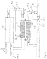
Fig. 4 eine schematische Darstellung der Flüssigkeitskreisläufe durch die Erwärmungsvorrichtung - Die
Figuren 1 bis 3 sind verschiedene Darstellungen einer Ausführungsvariante der Erwärmungsvorrichtung 1 mit einem monolithischen Wärmeübertrager 2 und zwei getrennten Gehäusehälften 6, 7. Wie inFig. 2 zu sehen ist, ragen beiderseits einer im Wesentlichen ebenen Grundplatte 2.1 einzelne Stifte 2.2, 2.3 auf, die einstückig mit der Grundplatte 2.1 ausgebildet sind. Die Stifte 2.2, 2.3 sind durch Fließpressen hergestellt. Sie haben über ihre Länge jeweils einen gleichbleibenden Durchmesser und ragen senkrecht von der Grundplatte 2.1 auf. - Die hier gezeigte runde Querschnittsversion ist nur beispielhaft. Je nach Strömungsanforderungen können die Stifte jede andere Querschnittsform wie oval oder eckig haben, wobei sie auch untereinander in Höhe, Dicke und Form verschieden sein können. Auch die Geometrie zueinander kann beliebig ausgestaltet sein, etwa um den Fluidstrom zu beeinflussen oder um sie auf Stege des Gehäuses abstimmen zu können. Die Anzahl der Stifte kann weitgehend frei gewählt werden. Um eine gute Wärmeübertragung zu erzielen sollten wenigstens fünf Stifte 2.2, 2.3 einstückig mit der Grundplatte 2.1 ausgebildet sein. Gute Ergebnisse werden insbesondere mit Grundplatten 2.1 erzielt, die zehn oder mehr Stifte 2.2, 2.3 aufweisen, beispielsweise wenigsten zwanzig Stifte 2.2, 2.3 oder sogar mehr als 50 Stifte 2.2, 2.3.
- Beide Seiten der Grundplatte 2.1 sind jeweils von einer Gehäusehälfte 6, 7 umgeben, die Grundplatte 2.1 liegt also zwischen den Gehäusehälften 6, 7. In diesen sind jeweils zwei Öffnungen 6.1, 7.1 an sich gegenüberliegenden Seiten (jeweils 2. Öffnung in den Zeichnungen nicht zu sehen) als Fluideinlass und Fluidauslass ausgebildet. Zusätzlich können auch noch weitere Öffnungen oder Bohrungen 6.2, 7.2 z.B. für Temperaturelemente vorhanden sein.
- Umlaufend um die Stifte 2.2, 2.3 sind auf beiden Seiten der Grundplatte 2.1 Dichtungen 4, 5 vorhanden, die die Fluide im Gehäuse 6, 7 der Erwärmungsvorrichtung 1 nach außen abdichten. Dadurch ist jedes Fluid für sich abgedichtet. Zur Vermischung der Fluide kann es daher auch dann nicht kommen, wenn eine der Dichtungen defekt ist.
- Weitere, bezogen auf die Gehäusehälften fluchtende, Durchbrüche 6.3, 7.3 sind vorgesehen, um die Erwärmungsvorrichtung aus Wärmeübertrager 2 und Gehäusehälften 6, 7 zu montieren. Mit Hilfe dieser Durchbrüche 6.3, 7.3 sind die Gehäusehälften 6, 7 mit zwischenliegenden Wärmeübertrager 2 dicht durch Komprimieren der Dichtungen 4, 5 gegeneinander verspannt. Dies erfolgt in diesem Ausführungsbeispiel durch eine Verschraubung, also durch die Durchbrühe hindurchgreifende Schrauben. Die Durchbrüche 6.3, 7.3 sind in einem Flansch auf gegenüberliegenden Längsseiten des Gehäuses angeordnet. Andere Arten der Verspannung, z.B. Verklipsen, auch ohne die Durchbrüche 6.3, 7.3 sind ebenso denkbar. Weiterhin kann auch bei einem mehrteiligen Gehäuse jedes Teil für sich dicht am Wärmeübertrager befestigt sein.
- In
Fig. 4 sind beispielhafte Flüssigkeitskreisläufe durch die Erwärmungsvorrichtung 1 dargestellt. Auf der unteren Hälfte im Bild wird die Erwärmungsvorrichtung 1 vom Kühlmittel eines Kfz durchflossen. Vor dem Durchfluss durch die Erwärmungsvorrichtung ist der Kühlmittelstrom aufgeteilt. Ein Teil 8.2 wird durch die Erwärmungsvorrichtung 1 geführt, ein anderer Teil 8.1 daran vorbei. Wie das Kühlmittel geführt wird, kann durch Ventile 9.1, 9.2 gesteuert werden, insbesondere mit Hilfe von Temperatursensoren wie 9.3. Beide Funktionen zusammen können beispielsweise auch von Thermostatventilen mit einem Dehnstoffelement wahrgenommen werden. - Nach dem Gegenstromprinzip, denkbar wäre aber auch das Gleichstrom- oder Kreuzstromprinzip, wird durch die obere Hälfte der Erwärmungsvorrichtung 1 Wasser zum Absenken der Temperatur im Verbrennungsraum vom Vorratsbehälter 10 zur Erwärmungsvorrichtung und wieder zurück als Kreislauf geführt. Davon zweigt eine Leitung 11.1 in Richtung Verbrennungsraum ab. Gespeist wird der Vorratsbehälter durch die Zuleitung 11.2, die Wasser von einem Kondensator oder durch Betankung zuführt. Um den Kreislauf aufrecht zu erhalten, kann weiterhin eine Pumpe 12 in den Kreislauf integriert sein. Die Pumpe kann beispielweise in Abhängigkeit von einem Sensor 13 gesteuert werden.
- Alle Leitungen des Systems können eine Beheizung 14 aufweisen. Zudem weist die Erwärmungsvorrichtung 1 ein elektrisches Heizelement, insbesondere ein PTC-Heizelement in wärmeleitender Verbindung zum Wärmeübertrager auf. Das Heizelement kann beispielsweise in oder an dem Gehäuse angebracht sein. Wenn zwei Grundplatten 2.1 vorgesehen sind, die jeweils nur auf einer Seite Stifte 2.2 aufweisen, kann das Heizelement auch zwischen den beiden Grundplatte angeordnet sein.
Claims (14)
- Erwärmungsvorrichtung für Fluide in einem Kraftfahrzeug mit mindestens einem Gehäuse und einem Wärmeübertrager (2), wobei der Wärmeübertrager (2) aufragend von einer Grundplatte (2.1) einzelne, einstückig mit der Grundplatte (2.1) verbundene Stifte (2.2, 2.3) zur Vergrößerung der Wärmeübertragungsfläche aufweist, dadurch gekennzeichnet, dass sie ein elektrisches PTC-Heizelement in wärmeleitender Verbindung zum Wärmeübertrager (2) aufweist.
- Erwärmungsvorrichtung nach Anspruch 1, dadurch gekennzeichnet, dass der Wärmeübertrager (2) beidseitig aufragend von einer Grundplatte (2.1) einzelne, einstückig mit der Grundplatte (2.1) verbundene Stifte (2.2, 2.3) aufweist.
- Erwärmungsvorrichtung nach Anspruch 1 oder 2, dadurch gekennzeichnet, dass der Wärmeübertrager (2) im Fließpressverfahren aus einem gut wärmeleitenden Material wie Aluminium oder Kupfer oder jeweils einer Legierung davon hergestellt ist, insbesondere im kombinierten Vorwärts- und Rückwärtsfließpressverfahren.
- Erwärmungsvorrichtung nach mindestens einem der vorhergehenden Ansprüche, dadurch gekennzeichnet, dass das Gehäuse von zwei getrennten, gegeneinander abgedichteten Fluiden durchströmt wird, die dabei Wärme austauschen.
- Erwärmungsvorrichtung nach mindestens einem der vorhergehenden Ansprüche, dadurch gekennzeichnet, dass ein durchströmendes Fluid das Kühlwasser eines Kühlwasserkreislaufes in einem Kfz ist.
- Erwärmungsvorrichtung nach mindestens einem der vorhergehenden Ansprüche, dadurch gekennzeichnet, dass ein durchströmendes Fluid ein Brennstoffadditiv zur Senkung der ausgestoßenen Schadstoffe wie Wasser oder Harnstofflösung ist.
- Erwärmungsvorrichtung nach mindestens einem der vorhergehenden Ansprüche, dadurch gekennzeichnet, dass das Gehäuse ein mehrteiliges Gehäuse, insbesondere zweiteiliges Gehäuse ist, das die beiden Fluidströme jeweils gegen den Wärmeübertrager (2) abdichtet.
- Erwärmungsvorrichtung nach Anspruch 7, dadurch gekennzeichnet, dass mindestens zwei Gehäuseteile (6, 7) des mehrteiligen Gehäuses mit dem zwischenliegenden Wärmeübertrager (2) gegeneinander verspannt sind.
- Erwärmungsvorrichtung nach Anspruch 8, dadurch gekennzeichnet, dass zwischen jedem der beiden Gehäuseteile (6, 7) und der Grundplatte (2.1) jeweils wenigstens eine Dichtung (4, 5) angeordnet ist.
- Erwärmungsvorrichtung nach Anspruch 8 oder 9, dadurch gekennzeichnet, dass jeder der beiden Gehäuseteile (6, 7) jeweils einen Fluideinlass (6.1, 7.1) und einen Fluidauslass (6.1, 7.1) aufweist.
- Erwärmungsvorrichtung nach eine der Ansprüche 8 bis 10, dadurch gekennzeichnet, dass die beiden Gehäuseteile (6, 7) an gegenüberliegenden Längsseiten eine Flansch aufweisen, der Durchbrüche (6.3, 7.3) für die beiden Gehäuseteile (6, 7) verbindende Schrauben aufweist.
- Erwärmungsvorrichtung nach mindestens einem der vorhergehenden Ansprüche, dadurch gekennzeichnet, dass das Gehäuse Umlenkeinrichtungen oder Trennstege aufweist, die die Strömung in ihrer Richtung beeinflussen.
- Erwärmungsvorrichtung nach mindestens einem der vorhergehenden Ansprüche, dadurch gekennzeichnet, dass das Gehäuse ein komprimierbares Ausdehnungselement aufweist.
- Erwärmungsvorrichtung nach mindestens einem der vorhergehenden Ansprüche, dadurch gekennzeichnet, dass die Grundplatte (2.1) einstückig mit wenigstens fünf Stiften (2.2. 2.3), vorzugsweise wenigstens zehn Stiften (2.2, 2.3) ausgebildet ist.
Applications Claiming Priority (1)
| Application Number | Priority Date | Filing Date | Title |
|---|---|---|---|
| DE102017006719.8A DE102017006719A1 (de) | 2017-07-17 | 2017-07-17 | Erwärmungsvorrichtung für Fluide in einem Kfz |
Publications (2)
| Publication Number | Publication Date |
|---|---|
| EP3431913A1 EP3431913A1 (de) | 2019-01-23 |
| EP3431913B1 true EP3431913B1 (de) | 2020-10-14 |
Family
ID=62975891
Family Applications (1)
| Application Number | Title | Priority Date | Filing Date |
|---|---|---|---|
| EP18183596.8A Active EP3431913B1 (de) | 2017-07-17 | 2018-07-16 | Erwärmungsvorrichtung für fluide in einem kfz |
Country Status (2)
| Country | Link |
|---|---|
| EP (1) | EP3431913B1 (de) |
| DE (1) | DE102017006719A1 (de) |
Families Citing this family (1)
| Publication number | Priority date | Publication date | Assignee | Title |
|---|---|---|---|---|
| WO2020159417A1 (en) * | 2019-02-03 | 2020-08-06 | Rolf Eriksson | Heat exchanger |
Citations (2)
| Publication number | Priority date | Publication date | Assignee | Title |
|---|---|---|---|---|
| DE3715194A1 (de) * | 1987-05-07 | 1988-11-24 | Kromberg & Schubert | Heizung fuer den fahrgastraum von kraftfahrzeugen |
| DE10320750A1 (de) * | 2003-05-09 | 2004-12-09 | Daimlerchrysler Ag | Klimaanlage |
Family Cites Families (5)
| Publication number | Priority date | Publication date | Assignee | Title |
|---|---|---|---|---|
| DE19701833A1 (de) * | 1997-01-21 | 1998-07-23 | Viessmann Werke Kg | Wärmetauscher |
| DE10315225B4 (de) * | 2003-03-31 | 2005-06-30 | Alutec Metallwaren Gmbh & Co. | Wärmetauscher |
| DE102010029663A1 (de) * | 2010-06-02 | 2011-12-08 | Willy Kretz | Wärmetauscher mit modularem Wärmeleitelement |
| JP6262422B2 (ja) * | 2012-10-02 | 2018-01-17 | 昭和電工株式会社 | 冷却装置および半導体装置 |
| WO2017093238A1 (de) * | 2015-12-02 | 2017-06-08 | Eichenauer Heizelemente Gmbh & Co. Kg | Reduktionsmittelsystem mit einem beheizbaren tank und verwendung einer heizeinrichtung zum beheizen eines reduktionsmitteltanks |
-
2017
- 2017-07-17 DE DE102017006719.8A patent/DE102017006719A1/de active Pending
-
2018
- 2018-07-16 EP EP18183596.8A patent/EP3431913B1/de active Active
Patent Citations (2)
| Publication number | Priority date | Publication date | Assignee | Title |
|---|---|---|---|---|
| DE3715194A1 (de) * | 1987-05-07 | 1988-11-24 | Kromberg & Schubert | Heizung fuer den fahrgastraum von kraftfahrzeugen |
| DE10320750A1 (de) * | 2003-05-09 | 2004-12-09 | Daimlerchrysler Ag | Klimaanlage |
Also Published As
| Publication number | Publication date |
|---|---|
| DE102017006719A1 (de) | 2019-01-17 |
| EP3431913A1 (de) | 2019-01-23 |
Similar Documents
| Publication | Publication Date | Title |
|---|---|---|
| EP1642076A1 (de) | Vorrichtung zum mehrstufigen wärmeaustausch und verfahren zur herstellung einer derartigen vorrichtung | |
| EP2501912A1 (de) | Saugrohr für einen verbrennungsmotor | |
| DE102008036277A1 (de) | Kühlanlage mit isolierten Kühlkreisläufen | |
| EP1911946A2 (de) | Vorrichtung zur Ladeluftkühlung für einen Verbrennungsmotor, System mit einer Vorrichtung zur Ladeluftkühlung | |
| DE60220700T2 (de) | Wärmetauschermodul mit hauptkühler und nebenkühler | |
| EP1955001A1 (de) | Kühlvorrichtung für eine verbrennungskraftmaschine | |
| EP2476975A2 (de) | Vorrichtung zur Wärmeübertragung für ein Fahrzeug | |
| DE102018113341B4 (de) | Vorrichtungen zur Wärmeübertragung | |
| EP1941224A1 (de) | Wärmetauscher | |
| WO2013190105A1 (de) | Thermoelektrisches modul mit wärmetauscher | |
| DE10160380A1 (de) | Vorrichtung zur Wärmeübertragung | |
| EP3521583B1 (de) | Kühlvorrichtung mit mindestens zwei kühlkreisläufen und einer gekühlten füllleitung | |
| DE2105657C3 (de) | Wärmetauscher | |
| EP3431913A1 (de) | Erwärmungsvorrichtung für fluide in einem kfz | |
| EP1977473A1 (de) | Batteriehalter | |
| WO2019072853A1 (de) | Abgaswärmeübertrager | |
| DE102014113868A1 (de) | Vorrichtung zur Wärmeübertragung | |
| WO2018158286A1 (de) | Heizeinrichtung | |
| DE69103044T2 (de) | Wärmetauscher mit kreisförmiger Strömung. | |
| EP3384138B1 (de) | Reduktionsmittelsystem mit einem beheizbaren tank und verwendung einer heizeinrichtung zum beheizen eines reduktionsmitteltanks | |
| EP3592967B1 (de) | Vorwärmeinrichtung | |
| DE10012197A1 (de) | Thermomanagement für ein Kraftfahrzeug mit einem Kühlmittelkreislauf und einer Klimaanlage | |
| EP1734324A2 (de) | Verstellbarer innerer Wärmeübertrager | |
| DE102021133181B4 (de) | Traktionsbatterie für ein elektrisch oder teilelektrisch angetriebenes Fahrzeug | |
| DE102024209401A1 (de) | Fluidverteilungsgehäuse, Thermomanagementsystem, Fahrzeug und Gebäude mit einem solchen Fluidverteilungsgehäuse |
Legal Events
| Date | Code | Title | Description |
|---|---|---|---|
| PUAI | Public reference made under article 153(3) epc to a published international application that has entered the european phase |
Free format text: ORIGINAL CODE: 0009012 |
|
| STAA | Information on the status of an ep patent application or granted ep patent |
Free format text: STATUS: THE APPLICATION HAS BEEN PUBLISHED |
|
| AK | Designated contracting states |
Kind code of ref document: A1 Designated state(s): AL AT BE BG CH CY CZ DE DK EE ES FI FR GB GR HR HU IE IS IT LI LT LU LV MC MK MT NL NO PL PT RO RS SE SI SK SM TR |
|
| AX | Request for extension of the european patent |
Extension state: BA ME |
|
| STAA | Information on the status of an ep patent application or granted ep patent |
Free format text: STATUS: REQUEST FOR EXAMINATION WAS MADE |
|
| 17P | Request for examination filed |
Effective date: 20190701 |
|
| RBV | Designated contracting states (corrected) |
Designated state(s): AL AT BE BG CH CY CZ DE DK EE ES FI FR GB GR HR HU IE IS IT LI LT LU LV MC MK MT NL NO PL PT RO RS SE SI SK SM TR |
|
| RIC1 | Information provided on ipc code assigned before grant |
Ipc: F28D 9/00 20060101ALI20200306BHEP Ipc: F28F 3/02 20060101AFI20200306BHEP Ipc: B60H 1/22 20060101ALI20200306BHEP |
|
| GRAP | Despatch of communication of intention to grant a patent |
Free format text: ORIGINAL CODE: EPIDOSNIGR1 |
|
| STAA | Information on the status of an ep patent application or granted ep patent |
Free format text: STATUS: GRANT OF PATENT IS INTENDED |
|
| INTG | Intention to grant announced |
Effective date: 20200429 |
|
| GRAS | Grant fee paid |
Free format text: ORIGINAL CODE: EPIDOSNIGR3 |
|
| GRAA | (expected) grant |
Free format text: ORIGINAL CODE: 0009210 |
|
| STAA | Information on the status of an ep patent application or granted ep patent |
Free format text: STATUS: THE PATENT HAS BEEN GRANTED |
|
| AK | Designated contracting states |
Kind code of ref document: B1 Designated state(s): AL AT BE BG CH CY CZ DE DK EE ES FI FR GB GR HR HU IE IS IT LI LT LU LV MC MK MT NL NO PL PT RO RS SE SI SK SM TR |
|
| REG | Reference to a national code |
Ref country code: GB Ref legal event code: FG4D Free format text: NOT ENGLISH |
|
| REG | Reference to a national code |
Ref country code: AT Ref legal event code: REF Ref document number: 1323988 Country of ref document: AT Kind code of ref document: T Effective date: 20201015 Ref country code: CH Ref legal event code: EP |
|
| REG | Reference to a national code |
Ref country code: DE Ref legal event code: R096 Ref document number: 502018002718 Country of ref document: DE |
|
| REG | Reference to a national code |
Ref country code: IE Ref legal event code: FG4D Free format text: LANGUAGE OF EP DOCUMENT: GERMAN |
|
| REG | Reference to a national code |
Ref country code: NL Ref legal event code: MP Effective date: 20201014 |
|
| PG25 | Lapsed in a contracting state [announced via postgrant information from national office to epo] |
Ref country code: GR Free format text: LAPSE BECAUSE OF FAILURE TO SUBMIT A TRANSLATION OF THE DESCRIPTION OR TO PAY THE FEE WITHIN THE PRESCRIBED TIME-LIMIT Effective date: 20210115 Ref country code: NO Free format text: LAPSE BECAUSE OF FAILURE TO SUBMIT A TRANSLATION OF THE DESCRIPTION OR TO PAY THE FEE WITHIN THE PRESCRIBED TIME-LIMIT Effective date: 20210114 Ref country code: FI Free format text: LAPSE BECAUSE OF FAILURE TO SUBMIT A TRANSLATION OF THE DESCRIPTION OR TO PAY THE FEE WITHIN THE PRESCRIBED TIME-LIMIT Effective date: 20201014 Ref country code: RS Free format text: LAPSE BECAUSE OF FAILURE TO SUBMIT A TRANSLATION OF THE DESCRIPTION OR TO PAY THE FEE WITHIN THE PRESCRIBED TIME-LIMIT Effective date: 20201014 Ref country code: PT Free format text: LAPSE BECAUSE OF FAILURE TO SUBMIT A TRANSLATION OF THE DESCRIPTION OR TO PAY THE FEE WITHIN THE PRESCRIBED TIME-LIMIT Effective date: 20210215 |
|
| REG | Reference to a national code |
Ref country code: LT Ref legal event code: MG4D |
|
| PG25 | Lapsed in a contracting state [announced via postgrant information from national office to epo] |
Ref country code: BG Free format text: LAPSE BECAUSE OF FAILURE TO SUBMIT A TRANSLATION OF THE DESCRIPTION OR TO PAY THE FEE WITHIN THE PRESCRIBED TIME-LIMIT Effective date: 20210114 Ref country code: PL Free format text: LAPSE BECAUSE OF FAILURE TO SUBMIT A TRANSLATION OF THE DESCRIPTION OR TO PAY THE FEE WITHIN THE PRESCRIBED TIME-LIMIT Effective date: 20201014 Ref country code: LV Free format text: LAPSE BECAUSE OF FAILURE TO SUBMIT A TRANSLATION OF THE DESCRIPTION OR TO PAY THE FEE WITHIN THE PRESCRIBED TIME-LIMIT Effective date: 20201014 Ref country code: IS Free format text: LAPSE BECAUSE OF FAILURE TO SUBMIT A TRANSLATION OF THE DESCRIPTION OR TO PAY THE FEE WITHIN THE PRESCRIBED TIME-LIMIT Effective date: 20210214 Ref country code: SE Free format text: LAPSE BECAUSE OF FAILURE TO SUBMIT A TRANSLATION OF THE DESCRIPTION OR TO PAY THE FEE WITHIN THE PRESCRIBED TIME-LIMIT Effective date: 20201014 Ref country code: ES Free format text: LAPSE BECAUSE OF FAILURE TO SUBMIT A TRANSLATION OF THE DESCRIPTION OR TO PAY THE FEE WITHIN THE PRESCRIBED TIME-LIMIT Effective date: 20201014 |
|
| PG25 | Lapsed in a contracting state [announced via postgrant information from national office to epo] |
Ref country code: NL Free format text: LAPSE BECAUSE OF FAILURE TO SUBMIT A TRANSLATION OF THE DESCRIPTION OR TO PAY THE FEE WITHIN THE PRESCRIBED TIME-LIMIT Effective date: 20201014 Ref country code: HR Free format text: LAPSE BECAUSE OF FAILURE TO SUBMIT A TRANSLATION OF THE DESCRIPTION OR TO PAY THE FEE WITHIN THE PRESCRIBED TIME-LIMIT Effective date: 20201014 |
|
| REG | Reference to a national code |
Ref country code: DE Ref legal event code: R097 Ref document number: 502018002718 Country of ref document: DE |
|
| PG25 | Lapsed in a contracting state [announced via postgrant information from national office to epo] |
Ref country code: SM Free format text: LAPSE BECAUSE OF FAILURE TO SUBMIT A TRANSLATION OF THE DESCRIPTION OR TO PAY THE FEE WITHIN THE PRESCRIBED TIME-LIMIT Effective date: 20201014 Ref country code: EE Free format text: LAPSE BECAUSE OF FAILURE TO SUBMIT A TRANSLATION OF THE DESCRIPTION OR TO PAY THE FEE WITHIN THE PRESCRIBED TIME-LIMIT Effective date: 20201014 Ref country code: CZ Free format text: LAPSE BECAUSE OF FAILURE TO SUBMIT A TRANSLATION OF THE DESCRIPTION OR TO PAY THE FEE WITHIN THE PRESCRIBED TIME-LIMIT Effective date: 20201014 Ref country code: LT Free format text: LAPSE BECAUSE OF FAILURE TO SUBMIT A TRANSLATION OF THE DESCRIPTION OR TO PAY THE FEE WITHIN THE PRESCRIBED TIME-LIMIT Effective date: 20201014 Ref country code: SK Free format text: LAPSE BECAUSE OF FAILURE TO SUBMIT A TRANSLATION OF THE DESCRIPTION OR TO PAY THE FEE WITHIN THE PRESCRIBED TIME-LIMIT Effective date: 20201014 Ref country code: RO Free format text: LAPSE BECAUSE OF FAILURE TO SUBMIT A TRANSLATION OF THE DESCRIPTION OR TO PAY THE FEE WITHIN THE PRESCRIBED TIME-LIMIT Effective date: 20201014 |
|
| PLBE | No opposition filed within time limit |
Free format text: ORIGINAL CODE: 0009261 |
|
| STAA | Information on the status of an ep patent application or granted ep patent |
Free format text: STATUS: NO OPPOSITION FILED WITHIN TIME LIMIT |
|
| PG25 | Lapsed in a contracting state [announced via postgrant information from national office to epo] |
Ref country code: DK Free format text: LAPSE BECAUSE OF FAILURE TO SUBMIT A TRANSLATION OF THE DESCRIPTION OR TO PAY THE FEE WITHIN THE PRESCRIBED TIME-LIMIT Effective date: 20201014 |
|
| 26N | No opposition filed |
Effective date: 20210715 |
|
| PG25 | Lapsed in a contracting state [announced via postgrant information from national office to epo] |
Ref country code: IT Free format text: LAPSE BECAUSE OF FAILURE TO SUBMIT A TRANSLATION OF THE DESCRIPTION OR TO PAY THE FEE WITHIN THE PRESCRIBED TIME-LIMIT Effective date: 20201014 Ref country code: AL Free format text: LAPSE BECAUSE OF FAILURE TO SUBMIT A TRANSLATION OF THE DESCRIPTION OR TO PAY THE FEE WITHIN THE PRESCRIBED TIME-LIMIT Effective date: 20201014 |
|
| PG25 | Lapsed in a contracting state [announced via postgrant information from national office to epo] |
Ref country code: SI Free format text: LAPSE BECAUSE OF FAILURE TO SUBMIT A TRANSLATION OF THE DESCRIPTION OR TO PAY THE FEE WITHIN THE PRESCRIBED TIME-LIMIT Effective date: 20201014 |
|
| REG | Reference to a national code |
Ref country code: CH Ref legal event code: PL |
|
| PG25 | Lapsed in a contracting state [announced via postgrant information from national office to epo] |
Ref country code: MC Free format text: LAPSE BECAUSE OF FAILURE TO SUBMIT A TRANSLATION OF THE DESCRIPTION OR TO PAY THE FEE WITHIN THE PRESCRIBED TIME-LIMIT Effective date: 20201014 |
|
| REG | Reference to a national code |
Ref country code: BE Ref legal event code: MM Effective date: 20210731 |
|
| PG25 | Lapsed in a contracting state [announced via postgrant information from national office to epo] |
Ref country code: LI Free format text: LAPSE BECAUSE OF NON-PAYMENT OF DUE FEES Effective date: 20210731 Ref country code: CH Free format text: LAPSE BECAUSE OF NON-PAYMENT OF DUE FEES Effective date: 20210731 |
|
| PG25 | Lapsed in a contracting state [announced via postgrant information from national office to epo] |
Ref country code: IS Free format text: LAPSE BECAUSE OF FAILURE TO SUBMIT A TRANSLATION OF THE DESCRIPTION OR TO PAY THE FEE WITHIN THE PRESCRIBED TIME-LIMIT Effective date: 20210214 Ref country code: LU Free format text: LAPSE BECAUSE OF NON-PAYMENT OF DUE FEES Effective date: 20210716 |
|
| PG25 | Lapsed in a contracting state [announced via postgrant information from national office to epo] |
Ref country code: IE Free format text: LAPSE BECAUSE OF NON-PAYMENT OF DUE FEES Effective date: 20210716 Ref country code: BE Free format text: LAPSE BECAUSE OF NON-PAYMENT OF DUE FEES Effective date: 20210731 |
|
| GBPC | Gb: european patent ceased through non-payment of renewal fee |
Effective date: 20220716 |
|
| PG25 | Lapsed in a contracting state [announced via postgrant information from national office to epo] |
Ref country code: GB Free format text: LAPSE BECAUSE OF NON-PAYMENT OF DUE FEES Effective date: 20220716 |
|
| PG25 | Lapsed in a contracting state [announced via postgrant information from national office to epo] |
Ref country code: CY Free format text: LAPSE BECAUSE OF FAILURE TO SUBMIT A TRANSLATION OF THE DESCRIPTION OR TO PAY THE FEE WITHIN THE PRESCRIBED TIME-LIMIT Effective date: 20201014 |
|
| PG25 | Lapsed in a contracting state [announced via postgrant information from national office to epo] |
Ref country code: HU Free format text: LAPSE BECAUSE OF FAILURE TO SUBMIT A TRANSLATION OF THE DESCRIPTION OR TO PAY THE FEE WITHIN THE PRESCRIBED TIME-LIMIT; INVALID AB INITIO Effective date: 20180716 |
|
| P01 | Opt-out of the competence of the unified patent court (upc) registered |
Effective date: 20230629 |
|
| PG25 | Lapsed in a contracting state [announced via postgrant information from national office to epo] |
Ref country code: MK Free format text: LAPSE BECAUSE OF FAILURE TO SUBMIT A TRANSLATION OF THE DESCRIPTION OR TO PAY THE FEE WITHIN THE PRESCRIBED TIME-LIMIT Effective date: 20201014 |
|
| REG | Reference to a national code |
Ref country code: AT Ref legal event code: MM01 Ref document number: 1323988 Country of ref document: AT Kind code of ref document: T Effective date: 20230716 |
|
| PG25 | Lapsed in a contracting state [announced via postgrant information from national office to epo] |
Ref country code: MT Free format text: LAPSE BECAUSE OF FAILURE TO SUBMIT A TRANSLATION OF THE DESCRIPTION OR TO PAY THE FEE WITHIN THE PRESCRIBED TIME-LIMIT Effective date: 20201014 |
|
| PG25 | Lapsed in a contracting state [announced via postgrant information from national office to epo] |
Ref country code: AT Free format text: LAPSE BECAUSE OF NON-PAYMENT OF DUE FEES Effective date: 20230716 |
|
| PG25 | Lapsed in a contracting state [announced via postgrant information from national office to epo] |
Ref country code: AT Free format text: LAPSE BECAUSE OF NON-PAYMENT OF DUE FEES Effective date: 20230716 |
|
| PGFP | Annual fee paid to national office [announced via postgrant information from national office to epo] |
Ref country code: DE Payment date: 20250731 Year of fee payment: 8 |
|
| PGFP | Annual fee paid to national office [announced via postgrant information from national office to epo] |
Ref country code: FR Payment date: 20250731 Year of fee payment: 8 |
|
| PG25 | Lapsed in a contracting state [announced via postgrant information from national office to epo] |
Ref country code: TR Free format text: LAPSE BECAUSE OF FAILURE TO SUBMIT A TRANSLATION OF THE DESCRIPTION OR TO PAY THE FEE WITHIN THE PRESCRIBED TIME-LIMIT Effective date: 20201014 |
|
| PGFP | Annual fee paid to national office [announced via postgrant information from national office to epo] |
Ref country code: AT Payment date: 20260410 Year of fee payment: 5 |