EP3431855A1 - Scr-verbindungsstelle - Google Patents
Scr-verbindungsstelle Download PDFInfo
- Publication number
- EP3431855A1 EP3431855A1 EP18176665.0A EP18176665A EP3431855A1 EP 3431855 A1 EP3431855 A1 EP 3431855A1 EP 18176665 A EP18176665 A EP 18176665A EP 3431855 A1 EP3431855 A1 EP 3431855A1
- Authority
- EP
- European Patent Office
- Prior art keywords
- connector body
- housing
- scr
- fluid line
- fluid
- Prior art date
- Legal status (The legal status is an assumption and is not a legal conclusion. Google has not performed a legal analysis and makes no representation as to the accuracy of the status listed.)
- Granted
Links
Images


Classifications
-
- F—MECHANICAL ENGINEERING; LIGHTING; HEATING; WEAPONS; BLASTING
- F16—ENGINEERING ELEMENTS AND UNITS; GENERAL MEASURES FOR PRODUCING AND MAINTAINING EFFECTIVE FUNCTIONING OF MACHINES OR INSTALLATIONS; THERMAL INSULATION IN GENERAL
- F16L—PIPES; JOINTS OR FITTINGS FOR PIPES; SUPPORTS FOR PIPES, CABLES OR PROTECTIVE TUBING; MEANS FOR THERMAL INSULATION IN GENERAL
- F16L53/00—Heating of pipes or pipe systems; Cooling of pipes or pipe systems
- F16L53/30—Heating of pipes or pipe systems
- F16L53/35—Ohmic-resistance heating
- F16L53/38—Ohmic-resistance heating using elongate electric heating elements, e.g. wires or ribbons
-
- F—MECHANICAL ENGINEERING; LIGHTING; HEATING; WEAPONS; BLASTING
- F16—ENGINEERING ELEMENTS AND UNITS; GENERAL MEASURES FOR PRODUCING AND MAINTAINING EFFECTIVE FUNCTIONING OF MACHINES OR INSTALLATIONS; THERMAL INSULATION IN GENERAL
- F16L—PIPES; JOINTS OR FITTINGS FOR PIPES; SUPPORTS FOR PIPES, CABLES OR PROTECTIVE TUBING; MEANS FOR THERMAL INSULATION IN GENERAL
- F16L25/00—Construction or details of pipe joints not provided for in, or of interest apart from, groups F16L13/00 - F16L23/00
- F16L25/01—Construction or details of pipe joints not provided for in, or of interest apart from, groups F16L13/00 - F16L23/00 specially adapted for realising electrical conduction between the two pipe ends of the joint or between parts thereof
-
- F—MECHANICAL ENGINEERING; LIGHTING; HEATING; WEAPONS; BLASTING
- F16—ENGINEERING ELEMENTS AND UNITS; GENERAL MEASURES FOR PRODUCING AND MAINTAINING EFFECTIVE FUNCTIONING OF MACHINES OR INSTALLATIONS; THERMAL INSULATION IN GENERAL
- F16L—PIPES; JOINTS OR FITTINGS FOR PIPES; SUPPORTS FOR PIPES, CABLES OR PROTECTIVE TUBING; MEANS FOR THERMAL INSULATION IN GENERAL
- F16L37/00—Couplings of the quick-acting type
- F16L37/08—Couplings of the quick-acting type in which the connection between abutting or axially overlapping ends is maintained by locking members
- F16L37/12—Couplings of the quick-acting type in which the connection between abutting or axially overlapping ends is maintained by locking members using hooks, pawls, or other movable or insertable locking members
- F16L37/1225—Couplings of the quick-acting type in which the connection between abutting or axially overlapping ends is maintained by locking members using hooks, pawls, or other movable or insertable locking members using a retaining member the extremities of which, e.g. in the form of a U, engage behind a shoulder of both parts
-
- F—MECHANICAL ENGINEERING; LIGHTING; HEATING; WEAPONS; BLASTING
- F16—ENGINEERING ELEMENTS AND UNITS; GENERAL MEASURES FOR PRODUCING AND MAINTAINING EFFECTIVE FUNCTIONING OF MACHINES OR INSTALLATIONS; THERMAL INSULATION IN GENERAL
- F16L—PIPES; JOINTS OR FITTINGS FOR PIPES; SUPPORTS FOR PIPES, CABLES OR PROTECTIVE TUBING; MEANS FOR THERMAL INSULATION IN GENERAL
- F16L41/00—Branching pipes; Joining pipes to walls
- F16L41/02—Branch units, e.g. made in one piece, welded, riveted
- F16L41/021—T- or cross-pieces
Definitions
- the invention relates to an SCR connection point, comprising a connector body, at least two fluid conduits and a housing surrounding the connector body and the end portions of the fluid conduits facing the connector body, wherein the connector body interconnects at least two fluid conduits and is insertable into the housing with the connected fluid conduits at least one fluid line is introduced into the connection point via an attachment point of the connector body in an insertion direction and is releasably connected to the connector body in the state not inserted in the housing, wherein the releasably connected fluid line has a holding means on its outer circumference, by means of which the fluid line in the connection point below Co-operation with a in the housing in the insertion direction of the fluid line in front of the connection point of the connector body arranged fixing element in the inserted state in the housing against loosening entge is secured gen the insertion direction.
- SCR junctions of the type described above are known in practice in various embodiments.
- aqueous urea solutions are known to be used in so-called SCR (Selective Catalytic Reduction) processes in motor vehicles in order to reduce the nitrogen content of exhaust gases. Due to this volume expansion or the associated pressure, the connectors and / or fluid lines can be damaged or even completely destroyed. This is especially true for connectors and fluid lines, which are used for the passage of aqueous urea solutions.
- the aqueous urea solution freezes Low temperatures and volume expansion, and by increasing the pressure can be connector or fluid lines of the SCR system damaged or completely destroyed. In principle, it is known to heat such connectors and / or the connected fluid lines. Nevertheless, an additional remedy for the occurrence of freezing of the solutions is desired.
- the holding means is supported via a spring element on a fixing element arranged in the housing, which is designed as a transverse wall in a leg of the housing, wherein the holding means is displaceable against the restoring force of the spring element in the direction of the fixing element.
- the assembly or manufacturing is relatively complicated, since the various spring elements must be placed before the insertion of the connector body together with the fluid lines in the housing on the fluid lines and must be kept under bias during insertion of the connector body with the inserted fluid lines so that they can be supported in the housing in the assembled state on the fixing.
- the heating conductors of the fluid lines must each be passed through a central opening through the fixing element and the spring element.
- both the fluid lines with the holding element relative to the connector body and the connector body relative to the housing in the housing between the fixing elements or the spring elements slidably. This may cause unwanted vibration in the SCR junction.
- the invention has for its object to provide an SCR junction of the aforementioned type, in which the above-described problems and disadvantages can be effectively avoided.
- the object is achieved by the features of the characterizing part of claim 1. Characterized in that in the housing at least one abutment is arranged, that fixes the connector body in the inserted state in the housing against displacement at least in the direction of insertion of the fluid line in the housing and in particular in that the abutment in such a way is formed and / or arranged that it fixes the connector body in the inserted state in the housing against tilting in the housing, unwanted movements and potential vibrations of the connector body are avoided.
- the fixing element or the holding element is designed to be elastically deformable counter to the insertion direction of the fluid line or, alternatively, an elastically deformable tolerance compensation element is arranged between the fixing element and the holding element.
- a play-free fit preferably a press fit, formed for receiving the connector body and the holding means or the connector body, the holding means and the tolerance compensation element. This reduces the required accuracy of the manufacturing tolerances of the individual parts of the fit and acts as a damping means to avoid vibrations.
- At least one heating conductor of at least one fluid line for heating the connector body is arranged on the outer circumference of the connector body.
- a fluid line is firmly connected to the connector body cohesively. This allows a particularly simple continuation of the heating of the fluid line to the connector body and a simple heating of the connector body.
- the heating wires of different fluid lines are formed on the inner wall of the housing guide channels for guiding the heating wires and / or receiving spaces for receiving connecting points, in particular electrical contact plugs. This facilitates the manufacture of the SCR joint and additionally reduces possible vibrations.
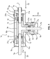
- FIG. 1 shows a first embodiment of an inventive SCR junction 1a.
- the SCR connection point 1a has a T-shaped connector body 3a which has at its three free ends in each case a connection point 5a for connecting a respective fluid line 7a, wherein the connection points 5a are fluidically connected to one another by means of a channel running through the connector body 3a.
- the connection points 5a are designed in particular as sleeves with an insertion opening 9 for insertion of the respective fluid line 7a, wherein they preferably have sealing means 12 on the inner circumference of the insertion opening 9.
- the fluid line 7a has a tube or a hose, at the end portions of which a holding means 11a arranged on the outer circumference of the fluid line 7a is arranged.
- the holding means 11a is in particular formed as an annular projection and preferably connected to the tube or hose by material bonding, in particular by means of laser welding.
- the holding means 11a closes up to reconcilsteckenden free end of the fluid line 7a, a male portion 13 of the fluid line 7a, which is preferably formed by the free end of the hose or tube.
- the fluid lines 7a are inserted with their insertion region 13 in each case in the connection point 5a of the connector body 3a.
- the SCR connection point 1a has a housing 15a enclosing the connector body 3a and the end sections of the fluid lines 7a.
- the housing 15a is preferably formed as a two-piece cap-shaped molding, which is preferably divided along a plane parallel to the longitudinal axis L of the connector body 3a.
- the fluid lines 7a are preferably first inserted into the connector body 3a, and then the connector body 3a, together with the inserted fluid lines 7a, inserted into a first housing half of the housing 15a. Thereafter, the first housing half is closed with a second housing half of the housing 15a.
- fixing elements 17a are formed in the housing 15a.
- the fixing elements 17a are designed such that they limit a movement of the holding means 11a of the fluid line 7a counter to the insertion direction E1, E2, E3 of the respective fluid line 7a.
- the fixing elements 17a are preferably designed as a stop bearing arranged in the insertion direction E1, E2, E3 of the respective fluid line 7a in front of the insertion opening 9 of the connector body 3a.
- the fixing element 17a is spaced from the insertion opening 9 such that the holding means 11a of the respective fluid line 7a is fixed between the fixing element 17a and an outer wall of the connector body 3a in the respective insertion direction E1, E2, E3 and counter to the respective insertion direction E1, E2, E3 ,
- the fixing elements 17a are formed as formed on the inner wall of the housing 15a lugs.
- the fixing element 17a is formed elastically deformable counter to the insertion direction E1, E2, E3 of the fluid line 7a.
- the fixing element 17a is preferably formed from an elastic plastic, in particular from a thermoplastic elastomer.
- At least one abutment 21a is arranged in the housing 15a, which fix the connector body 3a against displacement in the direction of one of the directions of insertion E1, E2, E3 of the respective fluid lines 7a in the housing 15a.
- the abutments 21a can also be designed such that they fix the connector body 3a against tilting in the housing 15a.
- the abutments 21a absorb the normal forces and moments occurring on the connector body 3a and prevent displacement or rotation of the connector body 3a in the housing 15a.
- Between the abutment 21a and the fixing element 17a is in particular a play-free fit, preferably a press fit, for receiving the connector body 3a and the holding means 11a formed.
- the abutment 21a is formed as an integrally formed on the inner wall of the housing 15a approach, which bears against the outer wall of the connector body 3a.
- a fixation pocket (not shown) is formed in the inner wall of the housing 15a, which receives the connector body 3a in a form-fitting manner and fixes it in the housing 15a.
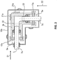
- FIG. 2 shows a second embodiment of the SCR junction 1b.
- the SCR junction 1b has an L-shaped connector body 3b having at its three free ends each a connection point 5a according to the first embodiment for connecting each of a fluid line 7a according to the first embodiment, wherein the connection points 5a by means of a connector body 3b current channel are fluidly interconnected.
- the second embodiment largely corresponds to the structure of the first embodiment according to FIG. 1 , wherein in the second embodiment according to FIG.
- abutment elements 22 are arranged, which prevent tilting of the connector body 3b in the housing 15b and / or center the connector body 3b in the housing 15b between the two housing halves of the housing 15b.
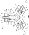
- FIG. 3 shows a third embodiment of the SCR junction 1c.
- the SCR connection point 1c has a Y-shaped connector body 3c which has at its three free ends in each case a connection point 5b for connecting a respective fluid line 7b, wherein the connection points 5b are fluidically connected to one another by means of a channel running through the connector body 3c.
- the connection points 5b are designed in particular as a plug-in section with a plug-in socket 10 for attaching the respective fluid line 7b, wherein they preferably have sealing means 12 on the outer circumference of the plug-in socket 10.
- the fluid line 7b has a tube or hose, on whose end portions a holding means 11b arranged on the outer circumference of the fluid line 7b is arranged.
- the holding means 11b is designed, in particular, as a connecting sleeve 25 placed on the free end of the tube or hose, which in the direction of the connector body 3b forms an insertion opening 9b for receiving the insertion piece 10 of the connector body 3c and in the direction of the fluid line 7b a receiving sleeve 26 for receiving having a hose or tube.
- the connecting sleeve 25 in the region of the receiving sleeve 26 with the hose or tube cohesively connected and in particular laser welded.
- the connecting sleeve 25 forms at its outer periphery in the transition from the receiving sleeve 26 to the insertion 9b a step-shaped stop 27.
- the fluid lines 7b are plugged with their connecting sleeves 25 each on the connection point 5b of the connector body 3c.
- the third embodiment of the SCR junction 1c has a case 15c surrounding the connector body 3c and the end portions of the fluid lines 7b.
- the housing 15c corresponds functionally as much as possible to the housing 15a of the first or 15b of the second embodiment, but is adapted to the different Y-shape of the third embodiment.
- fixing elements 17a are formed in the housing 15c according to the first embodiment.
- the fixing elements 17a are designed such that they move the holding means 11b of the fluid line 7b counter to the insertion direction E1, E2, E3 limit the respective fluid line 7b.
- the fixing elements 17a are designed as a stop bearing arranged in the insertion direction E1, E2, E3 of the respective fluid line 7b in front of the insertion piece 10 of the connector body 3c.
- the fixing element 17a is spaced from the insertion piece 10 such that the holding means 11b of the respective fluid line 7b is fixed between the fixing element 17a and an outer wall of the connector body 3c in the respective insertion direction E1, E2, E3 and counter to the respective insertion direction E1, E2, E3 ,
- At least one, in particular two, preferably three abutments 21b are arranged in the housing 15c, which fix the connector body 3c against displacement in the direction of one of the directions of insertion E1, E2, E3 of the respective fluid lines 7b in the housing 15c.
- the abutments 21b can also be designed such that they fix the connector body 3c against tilting in the housing 15c.
- the abutments 21b absorb the normal forces and moments occurring on the connector body 3c and prevent displacement or rotation of the connector body 3c in the housing 15c.
- Between the abutment 21a, 21b and the fixing element 17a is in particular a play-free fit, preferably a press fit, for receiving the connector body 3c and the holding means 11a, 11b formed.
- the abutment 21b is formed as an integrally formed on the inner wall of the housing 15c approach, which bears against the outer wall of the connector body 3c.
- a fixation pocket (not shown) is formed in the inner wall of the housing 15c, which receives the connector body 3c in a form-fitting manner and fixes it in the housing 15c.
- molded abutment elements 22 advantageously be present.
- FIGS. 4a and 4b show an alternative advantageous embodiment for the fixation of the fluid lines 7a, 7b at the connection points 5a, 5b of the connector body 3a, 3b, 3c according to the first three embodiments.
- On the fluid line 7a, 7b is preferably an elastically deformable tolerance compensation element 31 between the holding means 11a, 11b of the fluid line 7a, 7b and the fixing elements 17a of the housing 15a, 15b, 15c arranged.
- the fixing elements 17a are preferably rigid.
- the tolerance compensation element 31 is formed in particular as an O-ring of a thermoplastic elastomer.
- the tolerance compensation element 31 is designed such that it is arranged positionally stable on the fluid line 7a, 7b, so that it does not shift during insertion of the fluid line 7a, 7b in the connection points 5a, 5b.
- abutment 21a, 21b and the fixing element 17a is in particular a play-free fit, preferably a press fit, for receiving the connector body 3a, 3b, 3c, the tolerance compensation element 31 and the holding means 11a, 11b formed.
- the tolerance compensation element 31 can also be formed integrally with the holding means 11c.
- the holding means 11c is formed in particular as a two-component part, wherein on the end face of the holding means 11c facing the fixing element 17c, the tolerance-compensating function is formed of a thermoplastic elastomer component 33.
- the holding element 11c may be formed as a deformable in the insertion direction E1, E2, E3 mold element with a elastic effect giving shape, such as an S-dash or Z-blow in cross-section.
- the rigidly formed fixing element 17a can preferably be formed directly by the inner wall of the housing 15a (embodiment not shown), so that the retaining means 11c is arranged directly between the inner wall of the housing 15a and the connector body 3a.
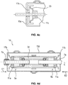
- FIG. 4d shows a fourth embodiment of an inventive SCR junction 1d.
- the SCR junction 1d has a cylindrical connector body 3d, which at its two free ends in each case one Connection point 5a according to the first or second embodiment for connecting each having a fluid line 7a according to the first or second embodiment, wherein the connection points 5a are fluidly connected to each other by means of a running through the connector body 3d channel.
- the SCR connection point 1d has a housing 15d enclosing the connector body 3d and the end sections of the fluid lines 7a.
- the housing 15d is preferably formed as a two-part cap-shaped molded part, which is preferably divided along a plane parallel to the longitudinal axis L of the connector body 3d.
- FIG. 4d a further alternative advantageous embodiment of a separate tolerance compensation element 31.
- the tolerance compensation function is achieved in one piece by means of an elastically deformable fixing element 17b.
- that fixing element 17b as a counter to the insertion direction E1, E2 deformable molding element with a elastic effect giving shaping, such as an S-shock or Z-blow in cross-section, or an elastic material selection, such as a thermoplastic elastomer formed his.
- abutment 21a, 21b and the fixing element 17b is in particular a play-free fit, preferably a press fit, for receiving the connector body 3a, 3b, 3c, 3d and the holding means 11a, 11b formed.
- the shape of the SCR connection point 1a, 1b, 1c, 1d as Y, T, corner, or cylinder part is basically independent of the type of connection points 5a, 5b, the type of fluid lines 7a, 7b and thus the holding means 11a , 11b or the type of fixing elements 17a, 17b. It is also fundamentally conceivable that not all connected fluid lines 7a, 7b are connected to connection points 5a, 5b of an SCR connection point 1a, 1b, 1c, 1d and / or fixed with fixing elements 17a, 17b.
- FIG. 5 shows a further advantageous embodiment of an SCR junction 1e.
- the SCR junction 1e is similar to the first embodiment as a T-shaped SCR junction 1e formed with three connected fluid lines.
- two connection points 5b of the connector body 3e according to the second embodiment are formed with fluid lines 7b according to the second embodiment, wherein the fixing elements 17b for the two fluid lines 7b according to the embodiment in FIG. 4d are formed.
- the third fluid line 7c without holding element 11a, 11b is formed and is only connected directly in an insertion with the connector body 3e cohesively.
- the connector body 3e may already be prefabricated with a fluid line 7c.
- the fluid lines 7a, 7b, 7c of the above-described embodiments of the SCR junctions 1a, 1b, 1c, 1d, 1e each have, in particular, two heating conductors 35a, 35b, 35c.
- FIG. 6 shows a sketch of the use of the heating element 35a for heating a connector body 3e. It is particularly advantageous if at least one heating conductor 35a of at least one fluid line 7c for heating the connector body 3e is arranged on the outer circumference of the connector body 3e. In particular, as in FIG. 6 both heating conductors 35a of a fluid line 7c for heating the connector body 3e are arranged on the outer circumference of the connector body 3e for heating.
- FIG. 7 shows a sketch of an SCR junction 1e according to FIG. 5 , wherein the left fluid line 7c is firmly connected to the connector body 3e cohesively, and wherein fixing 17a and tolerance compensation elements 31 according to the FIG. 4b are arranged. It is particularly advantageous if only the heating lines 35a of the permanently connected fluid line 7c for heating the connector body 3e are arranged on the outer circumference of the connector body 3e or the outer circumference of the connector body 3e is wrapped by these heating lines 35a.
- the heating conductors 35b, 35c of the fluid lines 7b inserted in the connection points 5b in the insertion direction E1, E2, E3 are guided laterally past the fixing elements 17a between the inner wall of the housing 15a and the connector body 3e, with a heating conductor 35a firmly connected Fluid line 7c is electrically connected to a heating conductor 35b of the one inserted fluid line 7b, and the other heating conductor 35b of the one inserted fluid line 7b is electrically connected to a heating conductor 35c of the other inserted fluid line 7b, and the other heating conductor 35c of the other inserted fluid line 7b the other arranged around the connector body 3e heating conductor 35a of the permanently connected fluid line 7c is electrically connected.
- heating wires 35a can already be arranged or wrapped before being inserted into the housing 15a on the connector body 3e which is prefabricated with a fluid line 7c.
- only one heating conductor 35a of the firmly cohesively connected fluid line 7c is used for heating the fluid body 3e.
- the described arrangement and interconnection of the heating conductors 35a, 35b, 35c is of principle independent of the various embodiments and can be used in all described embodiments, adapted to the number of fluid lines 7a, 7b, 7c used.
- the guide channels, bearings 39 or receiving spaces allow for easier installation and prevent slippage of the heating wires 35a, 35b, 35c and the connection points 37th
- the heating wires 35a, 35b, 35c are preferably connected to one another by means of electrical contact plugs which, on their outer circumference, have projections or diameter discontinuities relative to their joining direction (not shown).
- the receiving space on the inner wall of the housing 35a, 35b, 35c is formed such that a pair of assembled electrical contact plug are fitted form-fitting in the receiving space, so that the electrical contact plug positionally stable in the housing 15a, 15b, 15c are stored and prevents loosening of the electrical contact plug becomes. This allows easy insertion of the connection points 37 of the heating wires 35a, 35b, 35c in the housing half together with the connector body 3a, 3b, 3c, 3d and the fluid lines 7a, 7b, 7c.
- the fixing elements 17a and the abutments 21a are shown spaced apart in the figures from their adjacent elements, the retaining lug 11 of the fluid line 7a and the connector body 3a, although they are arranged as a transition fit or interference fit. This is merely illustrated in the handwritten drawing, but is not intended to mean an inevitable play between the fixing elements 17a and the holding lug 11 or the connector body 3a and between the abutment 21a and the connector body 3a.
- the invention is not limited to the illustrated and described embodiments, but also includes all the same in the context of the invention embodiments. It is expressly emphasized that the exemplary embodiments are not limited to all the features in combination, but rather each individual partial feature may also have an inventive meaning independently of all other partial features. Furthermore, the invention has hitherto not been limited to the feature combination defined in claim 1, but may also be defined by any other combination of certain features of all the individual features disclosed overall. This means that basically every single feature of claim 1 omitted or replaced by at least one disclosed elsewhere in the application individual feature.
Landscapes
- Engineering & Computer Science (AREA)
- General Engineering & Computer Science (AREA)
- Mechanical Engineering (AREA)
- Quick-Acting Or Multi-Walled Pipe Joints (AREA)
Abstract
Description
- Die Erfindung betrifft eine SCR-Verbindungsstelle, aufweisend einen Verbinderkörper, mindestens zwei Fluidleitungen und ein den Verbinderkörper und die dem Verbinderkörper zugewandten Endbereiche der Fluidleitungen umschließendes Gehäuse, wobei der Verbinderkörper mindestens zwei Fluidleitungen miteinander verbindet und mit den verbundenen Fluidleitungen in das Gehäuse einsetzbar ist, wobei mindestens eine Fluidleitung über eine Anschlussstelle des Verbinderkörpers in einer Einführrichtung in die Anschlussstelle eingeführt und im nicht in dem Gehäuse eingesetzten Zustand lösbar mit dem Verbinderkörper verbunden ist, wobei die lösbar verbundene Fluidleitung an ihrem Außenumfang ein Haltemittel aufweist, mittels dem die Fluidleitung in der Anschlussstelle unter Zusammenwirkung mit einem in dem Gehäuse in Einführrichtung der Fluidleitung vor der Anschlussstelle des Verbinderkörpers angeordneten Fixierelement im in dem Gehäuse eingesetzten Zustand gegen ein Lösen entgegen der Einführrichtung gesichert ist.
- SCR-Verbindungsstellen der vorstehend beschriebenen Art sind aus der Praxis in unterschiedlichen Ausführungsformen bekannt. Bei Verbindern und Fluidleitungen für die Durchleitung von wässrigen Medien besteht das Problem, dass bei niedrigen Temperaturen das wässrige Medium unter Volumenausdehnung gefriert. Solche wässrigen Harnstofflösungen werden bekanntlich im Rahmen so genannter SCR-Verfahren (Selective Catalytic Reduction) in Kraftfahrzeugen verwendet, um den Stickstoffgehalt von Abgasen zu reduzieren. Aufgrund dieser Volumenausdehnung bzw. des damit einhergehenden Drucks können die Verbinder und/oder Fluidleitungen beschädigt oder sogar vollständig zerstört werden. Das gilt vor allem auch für Verbinder und Fluidleitungen, die zur Durchleitung von wässrigen Harnstofflösungen eingesetzt werden. Die wässrige Harnstofflösung gefriert bei niedrigen Temperaturen unter Volumenausdehnung, und durch entsprechende Druckerhöhung können Verbinder und Fluidleitungen des SCR-Systems beschädigt oder vollständig zerstört werden. Grundsätzlich ist es bekannt, solche Verbinder und/oder die angeschlossenen Fluidleitungen zu beheizen. Nichtsdestoweniger ist eine zusätzliche Abhilfe beim Auftreten eines Gefrierens der Lösungen erwünscht.
- Bei bekannten SCR-Verbindungsstellen ist das Haltemittel über ein Federelement an einem in dem Gehäuse angeordnetes Fixierelement, dass als Querwand in einem Schenkel des Gehäuses ausgebildet ist, abgestützt, wobei das Haltemittel gegen die Rückstellkraft des Federelementes in Richtung des Fixierelementes verschiebbar ist. Bei dieser bekannten SCR-Verbindungsstelle ist die Montage beziehungsweise Herstellung relativ kompliziert, da die verschiedenen Federelemente vor dem Einsetzen des Verbinderkörpers zusammen mit den Fluidleitungen in das Gehäuse jeweils auf die Fluidleitungen aufgesetzt und während des Einsetzens des Verbinderkörpers mit den eingesteckten Fluidleitungen unter Vorspannung gehalten werden müssen, so dass sie sich im montierten Zustand im Gehäuse am Fixierelement abstützen können. Zudem müssen die Heizleiter der Fluidleitungen jeweils durch eine mittige Öffnung durch das Fixierelement und am Federelement vorbei geführt werden. Außerdem sowohl die Fluidleitungen mit dem Halteelement gegenüber dem Verbinderkörper als auch der Verbinderkörper gegenüber dem Gehäuse in dem Gehäuse zwischen den Fixierelementen beziehungsweise den Federelementen verschiebbar. Dadurch können ungewünschte Vibrationen in der SCR-Verbindungsstelle auftreten.
- Der Erfindung liegt die Aufgabe zugrunde, eine SCR-Verbindungsstelle der eingangs genannten Art zur Verfügung zu stellen, bei dem die vorstehend geschilderten Probleme und Nachteile effektiv vermieden werden können.
- Die Aufgabe wird erfindungsgemäß durch die Merkmale des kennzeichnenden Teils des Anspruchs 1 gelöst. Dadurch, dass in dem Gehäuse mindestens ein Widerlager angeordnet ist, dass den Verbinderkörper im in dem Gehäuse eingesetzten Zustand gegen ein Verschieben zumindest in Richtung der Einführrichtung der Fluidleitung in dem Gehäuse fixiert und insbesondere dadurch, dass das Widerlager derart ausgebildet und/oder angeordnet ist, dass es den Verbinderkörper im in dem Gehäuse eingesetzten Zustand gegen ein Verkippen in dem Gehäuse fixiert, werden ungewünschte Bewegungen und potentielle Vibrationen des Verbinderkörpers vermieden.
- Vorteilhafterweise ist das Fixierelement oder das Halteelement entgegen der Einführrichtung der Fluidleitung elastisch verformbar ausgebildet oder alternativ dazu zwischen Fixierelement und Halteelement ein elastisch verformbares Toleranzausgleichselement angeordnet. Insbesondere ist zwischen dem Widerlager und dem Fixierelement eine spielfreie Passung, vorzugsweise eine Presspassung, zur Aufnahme des Verbinderkörpers und des Haltemittels beziehungsweise des Verbinderkörpers, des Haltemittels und des Toleranzausgleichselementes ausgebildet. Dies reduziert die benötigte Genauigkeit der Herstellungstoleranzen der einzelnen Teile der Passung und wirkt als Dämpfungsmittel zur Vermeidung von Vibrationen.
- Besonders bevorzugt ist mindestens ein Heizleiter mindestens einer Fluidleitung zur Beheizung des Verbinderkörpers auf dem Außenumfang des Verbinderkörpers angeordnet ist. Insbesondere ist eine Fluidleitung fest mit dem Verbinderkörper stoffschlüssig verbunden ist. Dies ermöglicht eine besonders einfache Weiterführung des Heizleiters der Fluidleitung zum Verbinderkörper und eine einfache Beheizung des Verbinderkörpers.
- Insbesondere sind an der Innenwandung des Gehäuses Führungskanäle zur Führung der Heizdrähte und/oder Aufnahmeräume zur Aufnahme von Verbindungsstellen, insbesondere Elektrokontaktsteckern, der Heizdrähte unterschiedlicher Fluidleitungen ausgebildet. Dies erleichtert die Herstellung der SCR-Verbindungsstelle und reduziert zusätzlich mögliche Vibrationen.
- Weitere vorteilhafte Ausgestaltungen der Erfindung ergeben sich aus der folgenden Figurenbeschreibung und den abhängigen Unteransprüchen.
- Es zeigen:
- Fig. 1
- eine Skizze eines Längsschnitts einer ersten Ausführungsform einer erfindungsgemäßen SCR-Verbindungsstelle,
- Fig. 2
- eine Skizze eines Längsschnitts einer zweiten Ausführungsform einer erfindungsgemäßen SCR-Verbindungsstelle,
- Fig. 3
- eine Skizze eines Längsschnitts einer dritten Ausführungsform einer erfindungsgemäßen SCR-Verbindungsstelle,
- Fig. 4a
- eine Skizze eines Ausschnitts einer vorteilhaften Ausführung mit Toleranzausgleichselement im Bereich einer Anschlussstelle einer erfindungsgemäßen SCR-Verbindungsstelle,
- Fig. 4b
- eine Skizze eines Ausschnitts einer vorteilhaften Ausführung mit Toleranzausgleichselement im Bereich einer alternativen Anschlussstelle einer erfindungsgemäßen SCR-Verbindungsstelle,
- Fig. 4c
- eine Skizze eines Ausschnitts einer vorteilhaften Ausführung mit einem einteiligen Haltemittel mit Toleranzausgleich im Bereich einer Anschlussstelle einer erfindungsgemäßen SCR-Verbindungsstelle,
- Fig. 4d
- eine Skizze eines Längsschnitts einer vierten Ausführungsform einer erfindungsgemäßen SCR-Verbindungsstelle,
- Fig. 5
- eine Skizze eines Längsschnitts einer fünften Ausführungsform einer erfindungsgemäßen SCR-Verbindungsstelle mit einer stoffschlüssig verbundenen Fluidleitung,
- Fig. 6
- eine Skizze eine beispielhaften Verlaufs der Heizdrähte bei einer erfindungsgemäßen SCR-Verbindungsstelle,
- Fig. 7
- eine Skizze eines alternativen beispielhaften Verlaufs der Heizdrähte bei einer erfindungsgemäßen SCR-Verbindungsstelle.
- In den verschiedenen Figuren der Zeichnung sind gleiche Teile stets mit denselben Bezugszeichen versehen.
- Zu der anschließenden Beschreibung wird beansprucht, dass die Erfindung nicht auf die Ausführungsbeispiele und dabei nicht auf alle oder mehrere Merkmale von beschriebenen Merkmalskombinationen beschränkt ist, vielmehr ist jedes einzelne Teilmerkmal des/jedes Ausführungsbeispiels auch losgelöst von allen anderen im Zusammenhang damit beschriebenen Teilmerkmalen für sich und auch in Kombination mit beliebigen Merkmalen eines anderen Ausführungsbeispiels von Bedeutung für den Gegenstand der Erfindung.
-
Figur 1 zeigt eine erste Ausführungsform einer erfindungsgemäßen SCR-Verbindungsstelle 1a. Die SCR-Verbindungsstelle 1a weist einen T-förmigen Verbinderkörper 3a auf, der an seinen drei freien Enden jeweils eine Anschlussstelle 5a zum Verbinden jeweils einer Fluidleitung 7a aufweist, wobei die Anschlussstellen 5a mittels eines durch den Verbinderkörper 3a laufenden Kanals fluidisch miteinander verbunden sind. Die Anschlussstellen 5a sind insbesondere als Muffen mit einer Einstecköffnung 9 zum Einstecken der jeweiligen Fluidleitung 7a ausgebildet, wobei sie am Innenumfang der Einstecköffnung 9 vorzugsweise Dichtmittel 12 aufweisen. - Die Fluidleitung 7a weist ein Rohr oder einen Schlauch auf, an dessen Endabschnitten ein am Außenumfang der Fluidleitung 7a angeordnetes Haltemittel 11a angeordnet ist. Das Haltemittel 11a ist insbesondere als ein ringförmiger Ansatz ausgebildet uns vorzugsweise stoffschlüssig, insbesondere mittels Laserschweißen, mit dem Rohr oder Schlauch verbunden. An das Haltemittel 11a schließt sich bis zum einzusteckenden freien Ende der Fluidleitung 7a ein Einsteckbereich 13 der Fluidleitung 7a an, der vorzugsweise durch das freie Ende des Schlauches oder Rohres gebildet ist. Die Fluidleitungen 7a sind mit ihrem Einsteckbereich 13 jeweils in die Anschlussstelle 5a des Verbinderkörpers 3a eingesteckt.
- Zudem weist die SCR-Verbindungsstelle 1a ein den Verbinderkörper 3a und die Endabschnitte der Fluidleitungen 7a umhüllendes Gehäuse 15a auf. Das Gehäuse 15a ist vorzugsweise als ein zweiteiliges kappenförmiges Formteil ausgebildet, das vorzugsweise entlang einer Ebene parallel zur Längsachse L des Verbinderkörpers 3a geteilt ist. Bei der Montage werden vorzugsweise zunächst die Fluidleitungen 7a in den Verbinderkörper 3a eingesteckt und anschließend der Verbinderkörper 3a zusammen mit den eingesteckten Fluidleitungen 7a in eine erste Gehäusehälfte des Gehäuses 15a eingesetzt. Danach wird die erste Gehäusehälfte mit einer zweiten Gehäusehälfte des Gehäuses 15a verschlossen.
- Zur Fixierung der Verbindung der Fluidleitungen 7a mit dem Verbinderkörper 3a sind in dem Gehäuse 15a Fixierelemente 17a ausgebildet. Die Fixierelemente 17a sind derart ausgebildet, dass sie eine Bewegung des Haltemittels 11a der Fluidleitung 7a entgegen der Einführrichtung E1, E2, E3 der jeweiligen Fluidleitung 7a begrenzen. Vorzugsweise sind die Fixierelemente 17a als ein in Einführrichtung E1, E2, E3 der jeweiligen Fluidleitung 7a vor der Einstecköffnung 9 des Verbinderkörpers 3a angeordnetes Anschlaglager ausgebildet. Das Fixierelement 17a ist von der Einstecköffnung 9 derart beabstandet, dass das Haltemittel 11a der jeweiligen Fluidleitung 7a zwischen dem Fixierelement 17a und einer Außenwand des Verbinderkörpers 3a in der jeweiligen Einführrichtung E1, E2, E3 und entgegen der jeweiligen Einführrichtung E1, E2, E3 fixiert ist. Insbesondere sind die Fixierelemente 17a als an der Innenwand des Gehäuses 15a angeformte Ansätze ausgebildet. Vorteilhafterweise ist das Fixierelement 17a entgegen der Einführrichtung E1, E2, E3 der Fluidleitung 7a elastisch verformbar ausgebildet. Dazu ist das Fixierelement 17a vorzugsweise aus einem elastischen Kunststoff, insbesondere aus einem thermoplastischen Elastomer ausgebildet.
- Vorteilhafterweise ist in dem Gehäuse 15a mindestens ein Widerlager 21a angeordnet, das den Verbinderkörper 3a gegen ein Verschieben in Richtung einer der Einführrichtungen E1, E2, E3 der jeweiligen Fluidleitungen 7a in dem Gehäuse 15a fixieren. Zudem können die Widerlager 21a auch derart ausgebildet sein, dass sie den Verbinderkörper 3a gegen ein Verkippen in dem Gehäuse 15a fixieren. Die Widerlager 21a nehmen die an dem Verbinderkörper 3a auftretenden Normalkräfte und Momente und verhindern eine Verschiebung oder Drehung des Verbinderkörpers 3a in dem Gehäuse 15a. Zwischen dem Widerlager 21a und dem Fixierelement 17a ist insbesondere eine spielfreie Passung, vorzugsweise eine Presspassung, zur Aufnahme des Verbinderkörpers 3a und des Haltemittels 11a ausgebildet.
- Insbesondere ist das Widerlager 21a als ein an der Innenwand des Gehäuses 15a angeformter Ansatz ausgebildet, der an der Außenwandung des Verbinderkörpers 3a anliegt. Alternativ zum angeformten Ansatz ist in der Innenwand des Gehäuses 15a eine nicht dargestellte Fixiertasche geformt, die den Verbinderkörper 3a formschlüssig aufnimmt und in dem Gehäuse 15a fixiert.
-
Figur 2 zeigt eine zweite Ausführungsform der SCR-Verbindungsstelle 1b. Die SCR-Verbindungsstelle 1b weist einen L-förmigen Verbinderkörper 3b auf, der an seinen drei freien Enden jeweils eine Anschlussstelle 5a gemäß der ersten Ausführungsform zum Verbinden jeweils einer Fluidleitung 7a gemäß der ersten Ausführungsform aufweist, wobei die Anschlussstellen 5a mittels eines durch den Verbinderkörper 3b laufenden Kanals fluidisch miteinander verbunden sind. Ansonsten entspricht die zweite Ausführungsform weitestgehend dem Aufbau der ersten Ausführungsform gemäßFigur 1 , wobei bei der zweiten Ausführungsform gemäßFigur 2 am Außenumfang des Verbinderkörpers 3b oder am Innenumfang des Gehäuses 15b vorzugsweise Anlageelemente 22 angeordnet sind, die ein Verkippen des Verbinderkörpers 3b in dem Gehäuse 15b verhindern und/oder den Verbinderkörper 3b in dem Gehäuse 15b zwischen den beiden Gehäusehälften des Gehäuses 15b zentrieren. -
Figur 3 zeigt eine dritte Ausführungsform der SCR-Verbindungsstelle 1c. Die SCR-Verbindungsstelle 1c weist einen Y-förmigen Verbinderkörper 3c auf, der an seinen drei freien Enden jeweils eine Anschlussstelle 5b zum Verbinden jeweils einer Fluidleitung 7b aufweist, wobei die Anschlussstellen 5b mittels eines durch den Verbinderkörper 3c laufenden Kanals fluidisch miteinander verbunden sind. Die Anschlussstellen 5b sind insbesondere als Steckabschnitt mit einem Einsteckstutzen 10 zum Aufstecken der jeweiligen Fluidleitung 7b ausgebildet, wobei sie am Außenumfang des Einsteckstutzens 10 vorzugsweise Dichtmittel 12 aufweisen. - Die Fluidleitung 7b weist ein Rohr oder Schlauch auf, an dessen Endabschnitten ein am Außenumfang der Fluidleitung 7b angeordnetes Haltemittel 11b angeordnet ist. Das Haltemittel 11b ist insbesondere als eine auf dem freien Ende des Rohres oder des Schlauches aufgesetzte Verbindungsmuffe 25 ausgebildet, die in Richtung des Verbinderkörpers 3b eine Einstecköffnung 9b zur Aufnahme des Einsteckstutzens 10 des Verbinderkörpers 3c bildet und in Richtung der Fluidleitung 7b eine Aufnahmehülse 26 zur Aufnahme eines Schlauches oder Rohres aufweist. Vorzugsweise ist die Verbindungsmuffe 25 im Bereich der Aufnahmehülse 26 mit dem Schlauch oder Rohr stoffschlüssig verbunden und insbesondere lasergeschweißt. Dabei bildet die Verbindungsmuffe 25 an ihrem Außenumfang im Übergang von der Aufnahmehülse 26 zur Einstecköffnung 9b einen stufenförmigen Anschlag 27. Die Fluidleitungen 7b sind mit ihren Verbindungsmuffen 25 jeweils auf die Anschlussstelle 5b des Verbinderkörpers 3c aufgesteckt.
- Die dritte Ausführungsform der SCR-Verbindungsstelle 1c weist ein den Verbinderkörper 3c und die Endabschnitte der Fluidleitungen 7b umhüllendes Gehäuse 15c auf. Das Gehäuse 15c entspricht funktional weitestgehend dem Gehäuse 15a der ersten oder 15b der zweiten Ausführungsform, ist jedoch an die unterschiedliche Y-Form der dritten Ausführungsform angepasst.
- Zur Fixierung der Verbindung der Fluidleitungen 7b mit dem Verbinderkörper 3c sind in dem Gehäuse 15c entsprechend der ersten Ausführungsform Fixierelemente 17a ausgebildet. Die Fixierelemente 17a sind derart ausgebildet, dass sie eine Bewegung des Haltemittels 11b der Fluidleitung 7b entgegen der Einführrichtung E1, E2, E3 der jeweiligen Fluidleitung 7b begrenzen. Vorzugsweise sind die Fixierelemente 17a als ein in Einführrichtung E1, E2, E3 der jeweiligen Fluidleitung 7b vor dem Einsteckstutzen 10 des Verbinderkörpers 3c angeordnetes Anschlaglager ausgebildet. Das Fixierelement 17a ist von dem Einsteckstutzen 10 derart beabstandet, dass das Haltemittel 11b der jeweiligen Fluidleitung 7b zwischen dem Fixierelement 17a und einer Außenwand des Verbinderkörpers 3c in der jeweiligen Einführrichtung E1, E2, E3 und entgegen der jeweiligen Einführrichtung E1, E2, E3 fixiert ist.
- Vorteilhafterweise sind in dem Gehäuse 15c mindestens ein, insbesondere zwei, vorzugsweise drei Widerlager 21b angeordnet, die den Verbinderkörper 3c gegen ein Verschieben in Richtung einer der Einführrichtungen E1, E2, E3 der jeweiligen Fluidleitungen 7b in dem Gehäuse 15c fixieren. Zudem können die Widerlager 21b auch derart ausgebildet sein, dass sie den Verbinderkörper 3c gegen ein Verkippen in dem Gehäuse 15c fixieren. Die Widerlagen 21b nehmen die an dem Verbinderkörper 3c auftretenden Normalkräfte und Momente und verhindern eine Verschiebung oder Drehung des Verbinderkörpers 3c in dem Gehäuse 15c. Zwischen dem Widerlager 21a, 21b und dem Fixierelement 17a ist insbesondere eine spielfreie Passung, vorzugsweise eine Presspassung, zur Aufnahme des Verbinderkörpers 3c und des Haltemittels 11a, 11b ausgebildet.
- Insbesondere ist das Widerlager 21b als ein an der Innenwand des Gehäuses 15c angeformter Ansatz ausgebildet, der an der Außenwandung des Verbinderkörpers 3c anliegt. Alternativ zum angeformten Ansatz ist in der Innenwand des Gehäuses 15c eine nicht dargestellte Fixiertasche geformt, die den Verbinderkörper 3c formschlüssig aufnimmt und in dem Gehäuse 15c fixiert. Zudem können auch, wie bei der zweiten Ausführungsform gemäß
Figur 2 , angeformte Anlageelemente 22 vorteilhafterweise vorhanden sein. -
Figur 4a und 4b zeigen eine alternative vorteilhafte Ausführung für die Fixierung der Fluidleitungen 7a, 7b an den Anschlussstellen 5a, 5b der Verbinderkörper 3a, 3b, 3c gemäß den ersten drei Ausführungsformen. Auf der Fluidleitung 7a, 7b ist vorzugsweise ein elastisch verformbares Toleranzausgleichselement 31 zwischen den Haltemitteln 11a, 11b der Fluidleitung 7a, 7b und den Fixierelementen 17a des Gehäuses 15a, 15b, 15c angeordnet. Bei dieser Ausführungsform sind die Fixierelemente 17a vorzugsweise starr ausgebildet. Das Toleranzausgleichselement 31 ist insbesondere als O-Ring aus einem thermoplastischen Elastomer ausgebildet. Bei der Konfektionierung der Fluidleitung wird dazu das Toleranzausgleichselement 31 auf das Rohr oder den Schlauch geschoben, bevor das Haltemittel 11a, 11b auf dem Rohr oder dem Schlauch befestigt wird. Vorzugsweise ist das Toleranzausgleichselement 31 derart ausgebildet, dass es auf der Fluidleitung 7a, 7b positionsstabil angeordnet ist, so dass es sich beim Einstecken der Fluidleitung 7a, 7b in die Anschlussstellen 5a, 5b nicht verschiebt. Zwischen dem Widerlager 21a, 21b und dem Fixierelement 17a ist insbesondere eine spielfreie Passung, vorzugsweise eine Presspassung, zur Aufnahme des Verbinderkörpers 3a, 3b, 3c, des Toleranzausgleichselementes 31 und des Haltemittels 11a, 11b ausgebildet. - Gemäß
Figur 4c kann alternativ zu einem separaten Toleranzausgleichselement 31 das Toleranzausgleichselement 31 auch einteilig mit den Haltemitteln 11c gebildet werden. Dazu wird das Haltemittel 11c insbesondere als Zwei-Komponenten-Teil ausgebildet, wobei an der dem Fixierelement 17a zugewandten Stirnseite des Haltemittels 11c die den Toleranzausgleich gebende Funktion aus einer thermoplastischen Elastomer-Komponente 33 ausgebildet ist. Alternativ oder ergänzend kann das Halteelement 11c als ein in der Einführrichtung E1, E2, E3 verformbares Formelement mit einer einen elastischen Effekt gebenden Formgebung, wie zum Beispiel ein S-Schlag oder Z-Schlag im Querschnitt, ausgebildet sein. - Vorzugsweise kann das starr ausgebildete Fixierelement 17a direkt durch die Innenwandung des Gehäuses 15a gebildet sein (Ausführung nicht dargestellt), so dass sich das Haltemittel 11c unmittelbar zwischen Innenwandung des Gehäuses 15a und Verbinderkörper 3a angeordnet ist.
-
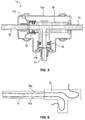
Figur 4d zeigt eine vierte Ausführungsform einer erfindungsgemäßen SCR-Verbindungsstelle 1d. Die SCR-Verbindungsstelle 1d weist einen zylinderförmigen Verbinderkörper 3d auf, der an seinen zwei freien Enden jeweils eine Anschlussstelle 5a gemäß der ersten oder zweiten Ausführungsform zum Verbinden jeweils einer Fluidleitung 7a gemäß der ersten oder zweiten Ausführungsform aufweist, wobei die Anschlussstellen 5a mittels eines durch den Verbinderkörper 3d laufenden Kanals fluidisch miteinander verbunden sind. - Zudem weist die SCR-Verbindungsstelle 1d ein den Verbinderkörper 3d und die Endabschnitte der Fluidleitungen 7a umhüllendes Gehäuse 15d auf. Das Gehäuse 15d ist vorzugsweise als ein zweiteiliges kappenförmiges Formteil ausgebildet, das vorzugsweise entlang einer Ebene parallel zur Längsachse L des Verbinderkörpers 3d geteilt ist.
- Zudem zeigt
Figur 4d eine weitere alternative vorteilhafte Ausführung zu einem separaten Toleranzausgleichselement 31. Dabei wird die den Toleranzausgleich gebende Funktion einteilig mittels eines elastisch verformbaren Fixierelementes 17b erreicht. Dazu kann dass Fixierelement 17b als ein entgegen der Einführrichtung E1, E2 verformbares Formelement mit einer einen elastischen Effekt gebenden Formgebung, wie zum Beispiel ein S-Schlag oder Z-Schlag im Querschnitt, oder einer elastischen Materialauswahl, wie zum Beispiel einem thermoplastischen Elastomer, ausgebildet sein. Zwischen dem Widerlager 21a, 21b und dem Fixierelement 17b ist insbesondere eine spielfreie Passung, vorzugsweise eine Presspassung, zur Aufnahme des Verbinderkörpers 3a, 3b, 3c, 3d und des Haltemittels 11a, 11b ausgebildet. - Grundsätzlich können die Merkmale der verschiedenen Ausführungsformen auch miteinander kombiniert werden. So ist die Formgebung der SCR-Verbindungsstelle 1a, 1b, 1c, 1d als Y-, T-, Eck-, oder Zylinderteil grundsätzlich unabhängig von der Art der Anschlussstellen 5a, 5b, der Art der Fluidleitungen 7a, 7b und damit der Haltemittel 11a, 11b oder der Art der Fixierelemente 17a, 17b. Auch ist es grundsätzlich denkbar, dass nicht alle angeschlossenen Fluidleitungen 7a, 7b mit Anschlussstellen 5a, 5b einer SCR-Verbindungsstelle 1a, 1b, 1c, 1d verbunden werden und/oder mit Fixierelementen 17a, 17b fixiert werden.
-
Figur 5 zeigt eine weitere vorteilhafte Ausführungsform einer SCR-Verbindungstelle 1e. Die SCR-Verbindungstelle 1e ist ähnlich zur ersten Ausführungsform als T-förmige SCR-Verbindungsstelle 1e mit drei angeschlossenen Fluidleitungen ausgebildet. Davon sind zwei Anschlussstellen 5b des Verbinderkörpers 3e gemäß der zweiten Ausführungsform mit Fluidleitungen 7b gemäß der zweiten Ausführungsform ausgebildet, wobei die Fixierelemente 17b für die beiden Fluidleitungen 7b gemäß der Ausführung inFigur 4d ausgebildet sind. Vorteilhafterweise ist die dritte Fluidleitung 7c ohne Halteelement 11a, 11b ausgebildet und wird lediglich unmittelbar in einer Einstecköffnung mit dem Verbinderkörper 3e stoffschlüssig verbunden. Insofern kann der Verbinderkörper 3e bereits mit einer Fluidleitung 7c vorkonfektioniert ausgebildet sein. - Die Fluidleitungen 7a, 7b, 7c der oben beschrieben Ausführungsformen der SCR-Verbindungsstellen 1a, 1b, 1c, 1d, 1e weisen jeweils insbesondere zwei Heizleiter 35a, 35b, 35c auf.
-
Figur 6 zeigt eine Skizze der Verwendung der Heizleiter 35a zur Beheizung eines Verbinderkörpers 3e. Dabei ist es besonders vorteilhaft, wenn mindestens ein Heizleiter 35a mindestens einer Fluidleitung 7c zur Beheizung des Verbinderkörpers 3e auf dem Außenumfang des Verbinderkörpers 3e angeordnet ist. Insbesondere sind wie inFigur 6 gezeigt beide Heizleiter 35a einer Fluidleitung 7c zur Beheizung des Verbinderkörpers 3e auf dem Außenumfang des Verbinderkörpers 3e zur Beheizung angeordnet. -
Figur 7 zeigt eine Skizze einer SCR-Verbindungsstelle 1e gemäßFigur 5 , wobei die linke Fluidleitung 7c fest mit dem Verbinderkörper 3e stoffschlüssig verbunden ist, und wobei Fixierelemente 17a und Toleranzausgleichselemente 31 gemäß derFigur 4b angeordnet sind. Dabei ist es besonders vorteilhaft, wenn nur die Heizleitungen 35a der fest verbundenen Fluidleitung 7c zur Beheizung des Verbinderkörpers 3e am Außenumfang des Verbinderkörpers 3e angeordnet sind beziehungsweise der Außenumfang des Verbinderkörpers 3e von diesen Heizleitungen 35a umwickelt ist. - Vorzugsweise werden die Heizleiter 35b, 35c der in die Anschlussstellen 5b gesteckten Fluidleitungen 7b in Einführrichtung E1, E2, E3 vor den Fixierelementen 17a seitlich an den Fixierelementen 17a zwischen der Innenwand des Gehäuses 15a und dem Verbinderkörper 3e vorbeigeführt, wobei ein Heizleiter 35a der fest verbundenen Fluidleitung 7c elektrisch mit einem Heizleiter 35b der einen gesteckten Fluidleitung 7b elektrisch verbunden ist, und der andere Heizleiter 35b der einen gesteckten Fluidleitung 7b elektrisch mit einem Heizleiter 35c der anderen gesteckten Fluidleitung 7b verbunden ist, und der andere Heizleiter 35c der anderen gesteckten Fluidleitung 7b mit dem anderen um den Verbinderkörper 3e angeordneten Heizleiter 35a der fest verbundenen Fluidleitung 7c elektrisch verbunden ist.
- Dies ermöglicht ein einfacheres Umwickeln, da hier keine Fixierelemente 17b oder Toleranzausgleichselemente 31 beim Führen der Heizdrähte 35a, 35b, 35c im Weg stehen. Zudem können die Heizdrähte 35a schon vor dem Einsetzen in das Gehäuse 15a an dem mit einer Fluidleitung 7c vorkonfektionierten Verbinderkörper 3e angeordnet beziehungsweise umwickelt werden. In einer weiter vorteilhaften Gestaltung wird nur genau ein Heizleiter 35a der fest stoffschlüssig verbundenen Fluidleitung 7c zur Beheizung des Fluidkörpers 3e verwendet.
- Die beschriebene Anordnung und Verschaltung der Heizleiter 35a, 35b, 35c ist vom Prinzip unabhängig von den verschiedenen Ausführungsformen und kann bei allen beschriebenen Ausführungsformen, angepasst an die Anzahl der verwendeten Fluidleitungen 7a, 7b, 7c, verwendet werden.
- In einer weiteren vorteilhaften Ausgestaltung sind an der Innenwandung des Gehäuses 15a, 15b, 15c, 15d Führungskanäle zur Führung der Heizdrähte 35a, 35b, 35c und/oder Lagerstellen 39 und/oder Aufnahmeräume zur Aufnahme von Verbindungsstellen 37, wie zum Beispiel Crimpstellen oder zusammengesteckte Elektrokontaktstecker der Heizdrähte 35a, 35b, 35c, ausgebildet. Die Führungskanäle, Lagerstellen 39 oder Aufnahmeräume ermöglichen eine einfachere Montage und verhindern ein Verrutschen der Heizdrähte 35a, 35b, 35c und der Verbindungsstellen 37.
- Vorzugsweise werden die Heizdrähte 35a, 35b, 35c mittels Elektrokontaktstecker miteinander verbunden, die an Ihrem Außenumfang bezogen auf ihre Fügerichtung Vorsprünge beziehungsweise Durchmessersprünge aufweisen (nicht dargestellt). Dabei ist der Aufnahmeraum an der Innenwand des Gehäuses 35a, 35b, 35c derart ausgebildet, dass ein Paar zusammengesetzte Elektrokontaktstecker formschlüssig in dem Aufnahmeraum eingepasst sind, so dass die Elektrokontaktstecker positionsstabil in dem Gehäuse 15a, 15b, 15c gelagert sind und ein Lösen der Elektrokontaktstecker verhindert wird. Dies ermöglicht ein einfaches Einsetzen der Verbindungsstellen 37 der Heizdrähte 35a, 35b, 35c in die Gehäusehälfte zusammen mit dem Verbinderkörper 3a, 3b, 3c, 3d und den Fluidleitungen 7a, 7b, 7c.
- Die Fixierelemente 17a und die Widerlager 21a sind in den Figuren von ihren benachbarten Elementen, dem Halteansatz 11 der Fluidleitung 7a beziehungsweise dem Verbinderkörper 3a beabstandet dargestellt, obwohl diese als Übergangspassung oder Presspassung angeordnet sind. Dies ist lediglich in der handschriftlichen Zeichnung so dargestellt, soll aber kein zwangsläufiges Spiel zwischen den Fixierelementen 17a und dem Halteansatz 11 oder dem Verbinderkörper 3a und zwischen dem Widerlager 21a und dem Verbinderkörper 3a bedeuten.
- Die Erfindung ist nicht auf die dargestellten und beschriebenen Ausführungsbeispiele beschränkt, sondern umfasst auch alle im Sinne der Erfindung gleichwirkenden Ausführungen. Es wird ausdrücklich betont, dass die Ausführungsbeispiele nicht auf alle Merkmale in Kombination beschränkt sind, vielmehr kann jedes einzelne Teilmerkmal auch losgelöst von allen anderen Teilmerkmalen für sich eine erfinderische Bedeutung haben. Ferner ist die Erfindung bislang auch noch nicht auf die im Anspruch 1 definierte Merkmalskombination beschränkt, sondern kann auch durch jede beliebige andere Kombination von bestimmten Merkmalen aller insgesamt offenbarten Einzelmerkmale definiert sind. Dies bedeutet, dass grundsätzlich praktisch jedes Einzelmerkmal des Anspruchs 1 weggelassen beziehungsweise durch mindestens ein an anderer Stelle der Anmeldung offenbartes Einzelmerkmal ersetzt werden kann.
-
- 1a, 1b, 1c, 1d, 1e
- SCR-Verbindungsstelle
- 3a, 3b, 3c, 3d, 3e
- Verbinderkörper
- 5a, 5b
- Anschlussstelle
- 7a, 7b, 7c
- Fluidleitung
- 9
- Einstecköffnung
- 10
- Einsteckstutzen
- 11a, 11b, 11c
- Haltemittel
- 12
- Dichtmittel
- 13
- Einsteckbereich
- 15a, 15b, 15c, 15d
- Gehäuse
- 17a, 17b, 17c
- Fixierelement
- 21a, 21b
- Widerlager
- 22
- Anlageelemente
- 25
- Verbindungsmuffe
- 26
- Aufnahmehülse
- 31
- Toleranzausgleichelement
- 33
- Elastisch verformbare Komponente
- 35a, 35b, 35c
- Heizleiter
- 37
- Verbindungsstellen
- 39
- Lagerstellen
- E1, E2, E3
- Einführrichtung
- L
- Längsachse
Claims (17)
- SCR-Verbindungsstelle (1a, 1b, 1c, 1d, 1e), aufweisend einen Verbinderkörper (3a, 3b, 3c, 3d, 3e), mindestens zwei Fluidleitungen (7a, 7b, 7c) und ein den Verbinderkörper (3a, 3b, 3c, 3d, 3e) und die dem Verbinderkörper (3a, 3b, 3c, 3d, 3e) zugewandten Endbereiche der Fluidleitungen (7a, 7b, 7c) umschließendes Gehäuse (15a, 15b, 15c, 15d), wobei der Verbinderkörper (3a, 3b, 3c, 3d, 3e) mindestens zwei Fluidleitungen (7a, 7b, 7c) miteinander verbindet und mit den verbundenen Fluidleitungen (7a, 7b, 7c) in das Gehäuse (15a, 15b, 15c, 15d) einsetzbar ist, wobei mindestens eine Fluidleitung (7a, 7b) über eine Anschlussstelle (5a, 5b) des Verbinderkörpers (3a, 3b, 3c, 3d, 3e) in einer Einführrichtung (E1, E2, E3) in die Anschlussstelle (5a, 5b) eingeführt und im nicht in dem Gehäuse (15a, 15b, 15c, 15d) eingesetzten Zustand lösbar mit dem Verbinderkörper (3a, 3b, 3c, 3d, 3e) verbunden ist, wobei die lösbar verbundene Fluidleitung (7a, 7b) an ihrem Außenumfang ein Haltemittel (11a, 11b) aufweist, mittels dem die Fluidleitung (7a, 7b) in der Anschlussstelle (5a, 5b) unter Zusammenwirkung mit einem in dem Gehäuse (15a, 15b, 15c, 15d) in Einführrichtung (E1, E2, E3) der Fluidleitung (7a, 7b) vor der Anschlussstelle (5a, 5b) des Verbinderkörpers (3a, 3b, 3c, 3d, 3e) angeordneten Fixierelement (17a, 17b, 17c) im in dem Gehäuse (15a, 15b, 15c, 15d) eingesetzten Zustand gegen ein Lösen entgegen der Einführrichtung (E1, E2, E3) gesichert ist,
dadurch gekennzeichnet, dass
in dem Gehäuse mindestens ein Widerlager (21a, 21b) angeordnet ist, dass den Verbinderkörper (3a, 3b, 3c, 3d, 3e) im in dem Gehäuse eingesetzten Zustand gegen ein Verschieben zumindest in Richtung der Einführrichtung (E1, E2, E3) der Fluidleitung (7a, 7b, 7c) in dem Gehäuse (15a, 15b, 15c, 15d) fixiert. - SCR-Verbindungsstelle (1a, 1b, 1c, 1d, 1e) nach Anspruch 1,
dadurch gekennzeichnet, dass
das Widerlager (21a, 21b) derart ausgebildet und/oder angeordnet ist, dass es den Verbinderkörper (3a, 3b, 3c, 3d, 3e) im in dem Gehäuse (15a, 15b, 15c, 15d) eingesetzten Zustand gegen ein Verkippen in dem Gehäuse (15a, 15b, 15c, 15d) fixiert. - SCR-Verbindungsstelle (1a, 1b, 1c, 1d, 1e) nach Anspruch 1 oder 2,
dadurch gekennzeichnet, dass
am Außenumfang des Verbinderkörpers (3a, 3b, 3c, 3d, 3e) oder am Innenumfang des Gehäuses (15a, 15b, 15c, 15d) Anlageelemente (22) angeordnet sind, die ein Verkippen des Verbinderkörpers (3a, 3b, 3c, 3d, 3e) in dem Gehäuse (15a, 15b, 15c, 15d) verhindern. - SCR-Verbindungsstelle (1a, 1b, 1c, 1d, 1e) nach einem der Ansprüche 1 bis 3,
dadurch gekennzeichnet, dass
das Fixierelement (17a, 17b, 17c) entgegen der Einführrichtung (E1, E2, E3) der Fluidleitung (7a, 7b, 7c) oder das Halteelement (11a, 11b, 11c) in Einführrichtung der Fluidleitung (7a, 7b, 7c) elastisch verformbar ausgebildet ist. - SCR-Verbindungsstelle (1a, 1b, 1c, 1d, 1e) nach Anspruch 4,
dadurch gekennzeichnet, dass
das Halteelement (11a, 11b, 11c) als ein Zwei-Komponenten-Teil ausgebildet ist und eine elastisch verformbare Komponente (33) einteilig mit dem Halteelement (11a, 11b, 11c) auf der dem Fixierelement (17a, 17b, 17c) gegenüberliegenden Seite des Halteelementes (11a, 11b, 11c) ausgebildet ist. - SCR-Verbindungsstelle (1a, 1b, 1c, 1d, 1e) nach Anspruch 4,
dadurch gekennzeichnet, dass
das Halteelement (11a, 11b, 11c) als ein in der Einführrichtung (E1, E2, E3) verformbares Formelement mit einer einen elastischen Effekt gebenden Formgebung ausgebildet ist. - SCR-Verbindungsstelle (1a, 1b, 1c, 1d, 1e) nach einem der Ansprüche 4 bis 6,
dadurch gekennzeichnet, dass
zwischen dem Widerlager (21a, 21b) und dem Fixierelement (17a, 17b, 17c) eine spielfreie Passung, vorzugsweise eine Presspassung, zur Aufnahme des Verbinderkörpers (3a, 3b, 3c, 3d, 3e) und des Haltemittels (11a, 11b) ausgebildet ist. - SCR-Verbindungsstelle (1a, 1b, 1c, 1d, 1e) nach einem der Ansprüche 1 bis 3,
dadurch gekennzeichnet, dass
zwischen Fixierelement (17a, 17b, 17c) und Halteelement (11a, 11b, 11c) ein elastisch verformbares Toleranzausgleichselement (31) angeordnet ist. - SCR-Verbindungsstelle (1a, 1b, 1c, 1d, 1e) nach Anspruch 8,
dadurch gekennzeichnet, dass
das Toleranzausgleichselement (31) aus einem thermoplastischen Elastomer ausgebildet ist. - SCR-Verbindungsstelle (1a, 1b, 1c, 1d, 1e) nach Anspruch 8 oder 9,
dadurch gekennzeichnet, dass
das Toleranzausgleichselement (31) als ein auf der Fluidleitung (7a, 7b, 7c) sitzender O-Ring ausgebildet ist. - SCR-Verbindungsstelle (1a, 1b, 1c, 1d, 1e) nach Anspruch 8, 9 oder 10,
dadurch gekennzeichnet, dass
zwischen dem Widerlager (21a, 21b) und dem Fixierelement (17a, 17b, 17c) eine spielfreie Passung, vorzugsweise eine Presspassung, zur Aufnahme des Verbinderkörpers (3a, 3b, 3c, 3d, 3e), des Haltemittels (11a, 11b) und des Toleranzausgleichselementes (31) ausgebildet ist. - SCR-Verbindungsstelle (1a, 1b, 1c, 1d, 1e) nach einem der Ansprüche 1 bis 11,
dadurch gekennzeichnet, dass
mindestens ein Heizleiter (35a, 35b, 35c) mindestens einer Fluidleitung (7a, 7b, 7c) zur Beheizung des Verbinderkörpers (3a, 3b, 3c, 3d, 3e) auf dem Außenumfang des Verbinderkörpers (3a, 3b, 3c, 3d, 3e) angeordnet ist. - SCR-Verbindungsstelle (1a, 1b, 1c, 1d, 1e) nach einem der Ansprüche 1 bis 12,
dadurch gekennzeichnet, dass
eine Fluidleitung (7a, 7b, 7c) fest mit dem Verbinderkörper (3a, 3b, 3c, 3d, 3e) stoffschlüssig verbunden ist. - SCR-Verbindungsstelle (1a, 1b, 1c, 1d, 1e) nach Anspruch 13,
dadurch gekennzeichnet, dass
nur die Heizleitungen (35a, 35b, 35c) der fest verbundenen Fluidleitung (7a, 7b, 7c) zur Beheizung des Verbinderkörpers (3a, 3b, 3c, 3d, 3e) am Außenumfang des Verbinderkörpers (3a, 3b, 3c, 3d, 3e) angeordnet sind. - SCR-Verbindungsstelle (1a, 1b, 1c, 1d, 1e) nach einem der Ansprüche 12 bis 14,
dadurch gekennzeichnet, dass
die Heizleiter (35a, 35b, 35c) der in die Anschlussstellen (5a, 5b) gesteckten Fluidleitungen (7a, 7b, 7c) in Einführrichtung (E1, E2, E3) vor den Fixierelementen (17a, 17b, 17c) seitlich an den Fixierelementen (17a, 17b, 17c) zwischen der Innenwand des Gehäuses (15a, 15b, 15c, 15d) und dem Verbinderkörper (3a, 3b, 3c, 3d, 3e) vorbeigeführt sind. - SCR-Verbindungsstelle (1a, 1b, 1c, 1d, 1e) nach einem der Ansprüche 1 bis 15,
dadurch gekennzeichnet, dass
an der Innenwandung des Gehäuses (15a, 15b, 15c, 15d) Führungskanäle zur Führung der Heizdrähte (35a, 35b, 35c) und/oder Lagerstellen (39) und/oder Aufnahmeräume zur Aufnahme von Verbindungsstellen (37) der Heizdrähte (35a, 35b, 35c) ausgebildet sind. - SCR-Verbindungsstelle (1a, 1b, 1c, 1d, 1e) nach Anspruch 16,
dadurch gekennzeichnet, dass
der Aufnahmeraum zur Aufnahme von Verbindungsstellen (37) der Heizdrähte (35a, 35b, 35c) an der Innenwand des Gehäuses (35a, 35b, 35c) derart ausgebildet ist, dass ein Paar zusammengesetzte Elektrokontaktstecker der Heizdrähte (35a, 35b, 35c) formschlüssig in dem Aufnahmeraum eingepasst ist.
Applications Claiming Priority (1)
| Application Number | Priority Date | Filing Date | Title |
|---|---|---|---|
| DE202017104371.1U DE202017104371U1 (de) | 2017-07-21 | 2017-07-21 | SCR-Verbindungsstelle |
Publications (2)
| Publication Number | Publication Date |
|---|---|
| EP3431855A1 true EP3431855A1 (de) | 2019-01-23 |
| EP3431855B1 EP3431855B1 (de) | 2020-12-16 |
Family
ID=62567516
Family Applications (1)
| Application Number | Title | Priority Date | Filing Date |
|---|---|---|---|
| EP18176665.0A Active EP3431855B1 (de) | 2017-07-21 | 2018-06-08 | Scr-verbindungsstelle |
Country Status (2)
| Country | Link |
|---|---|
| EP (1) | EP3431855B1 (de) |
| DE (1) | DE202017104371U1 (de) |
Cited By (4)
| Publication number | Priority date | Publication date | Assignee | Title |
|---|---|---|---|---|
| CN109812638A (zh) * | 2019-03-27 | 2019-05-28 | 陆挚译 | 一种大口径三通管 |
| WO2019134803A1 (de) * | 2018-01-02 | 2019-07-11 | Voss Automotive Gmbh | Leitungssystem zum transport von wässrigen reduktionsmitteln für die abgasnachbehandlung |
| WO2020011484A1 (de) * | 2018-07-13 | 2020-01-16 | Voss Automotive Gmbh | Verbindungsanordnung, insbesondere zum durchführen von wässrigen harnstofflösungen |
| IT201900007010A1 (it) * | 2019-05-20 | 2020-11-20 | Hutchinson Srl | Linea per un fluido riscaldabile comprendente più condotti, in particolare per un sistema SCR o un sistema di iniezione ad acqua, e processo di assemblaggio. |
Citations (4)
| Publication number | Priority date | Publication date | Assignee | Title |
|---|---|---|---|---|
| DE202007010502U1 (de) * | 2007-07-26 | 2008-11-27 | Voss Automotive Gmbh | Konfektionierte Medienleitung |
| DE202011051325U1 (de) * | 2011-09-16 | 2011-12-01 | Parker Hannifin Manufacturing Germany GmbH & Co. KG | Unter Druck drehbare Anschluss- und Verbindungsvorrichtung für Hochdruckleitungen |
| DE102013103534A1 (de) * | 2013-04-09 | 2014-10-09 | Voss Automotive Gmbh | "Steckverbindungsteil für einen Leitungsverbinder, insbesondere für eine konfektionierte Medienleitung" |
| DE202017101274U1 (de) * | 2017-03-06 | 2017-03-24 | TI Automotive (Fuldabrück) GmbH | Verbindungsaggregat |
-
2017
- 2017-07-21 DE DE202017104371.1U patent/DE202017104371U1/de active Active
-
2018
- 2018-06-08 EP EP18176665.0A patent/EP3431855B1/de active Active
Patent Citations (4)
| Publication number | Priority date | Publication date | Assignee | Title |
|---|---|---|---|---|
| DE202007010502U1 (de) * | 2007-07-26 | 2008-11-27 | Voss Automotive Gmbh | Konfektionierte Medienleitung |
| DE202011051325U1 (de) * | 2011-09-16 | 2011-12-01 | Parker Hannifin Manufacturing Germany GmbH & Co. KG | Unter Druck drehbare Anschluss- und Verbindungsvorrichtung für Hochdruckleitungen |
| DE102013103534A1 (de) * | 2013-04-09 | 2014-10-09 | Voss Automotive Gmbh | "Steckverbindungsteil für einen Leitungsverbinder, insbesondere für eine konfektionierte Medienleitung" |
| DE202017101274U1 (de) * | 2017-03-06 | 2017-03-24 | TI Automotive (Fuldabrück) GmbH | Verbindungsaggregat |
Cited By (6)
| Publication number | Priority date | Publication date | Assignee | Title |
|---|---|---|---|---|
| WO2019134803A1 (de) * | 2018-01-02 | 2019-07-11 | Voss Automotive Gmbh | Leitungssystem zum transport von wässrigen reduktionsmitteln für die abgasnachbehandlung |
| WO2020011484A1 (de) * | 2018-07-13 | 2020-01-16 | Voss Automotive Gmbh | Verbindungsanordnung, insbesondere zum durchführen von wässrigen harnstofflösungen |
| US11486529B2 (en) | 2018-07-13 | 2022-11-01 | Voss Automotive Gmbh | Connection assembly, in particular for conducting aqueous urea solutions |
| CN109812638A (zh) * | 2019-03-27 | 2019-05-28 | 陆挚译 | 一种大口径三通管 |
| IT201900007010A1 (it) * | 2019-05-20 | 2020-11-20 | Hutchinson Srl | Linea per un fluido riscaldabile comprendente più condotti, in particolare per un sistema SCR o un sistema di iniezione ad acqua, e processo di assemblaggio. |
| WO2020234738A1 (en) * | 2019-05-20 | 2020-11-26 | Hutchinson S.R.L. | Line for a heated fluid comprising more conduits, in particular for an scr system or an injection system for water and assembly process |
Also Published As
| Publication number | Publication date |
|---|---|
| EP3431855B1 (de) | 2020-12-16 |
| DE202017104371U1 (de) | 2018-10-23 |
Similar Documents
| Publication | Publication Date | Title |
|---|---|---|
| EP1617517B1 (de) | Verbindung zwischen einem Kabelendstück und einem Kabelende | |
| DE3143015C2 (de) | ||
| DE102006062894B4 (de) | Schutzkappe | |
| EP3431855B1 (de) | Scr-verbindungsstelle | |
| DE69713990T2 (de) | Axial belastbare Verbindungsanordnung | |
| EP1939514A1 (de) | Verbindungsanordnung mit Rohrstutzen zum Verbinden von Fluidaufnahmeteilen | |
| DE102014221970A1 (de) | Stifteinheit für ein Verbindergehäuse und Verbindergehäuse hiermit | |
| EP3270028B1 (de) | Kupplungsteil für einen steckverbinder zur herstellung von schlauch- und/oder rohrverbindungen und steckverbinder mit einem derartigen kupplungsteil | |
| DE4307514C2 (de) | Verbinder für dünne Rohre | |
| DE102016117219A1 (de) | Geführte Steckverbindung | |
| DE202017101274U1 (de) | Verbindungsaggregat | |
| WO2022078941A1 (de) | Elastischer steckverbinder | |
| WO2006039882A1 (de) | Anschlussanordnung zum anschliessen einer rohrleitung an ein system | |
| DE102017103039B3 (de) | Heizeinheit zum Beheizen von Flüssigkeiten in einem Kraftfahrzeug | |
| DE102014111436A1 (de) | Kupplungsanordnung, insbesondere Rohrkupplung | |
| DE102023113116A1 (de) | Temperierbare Stromleitungsvorrichtung, Verfahren zu deren Herstellung und Verfahren zum Temperieren einer Stromleitung | |
| DE102013113813A1 (de) | Steckverbinder zum Anbinden einer medienführenden Fluidleitung eines Kraftfahrzeugs | |
| DE202012008100U1 (de) | Vorrichtung zum schwingungsentkoppelten Verbinden zweier Einrichtungen einer Abgasanlage | |
| EP1513225A2 (de) | Verriegelungselement für eine Steckverbindung | |
| EP3821162B1 (de) | Verbindungsanordnung, insbesondere zum durchführen von wässrigen harnstofflösungen | |
| DE102022105073B4 (de) | Kontaktbuchse | |
| DE1765099B2 (de) | Elektrische steckvorrichtung | |
| EP1970614B1 (de) | Schlaucharmatur für einen Schlauch mit mehreren Schlauchkammern | |
| EP3982027A1 (de) | Steckverbinder mit rückstellelement | |
| DE102022211532A1 (de) | Kühler und Verfahren zur Herstellung eines Kühlers |
Legal Events
| Date | Code | Title | Description |
|---|---|---|---|
| PUAI | Public reference made under article 153(3) epc to a published international application that has entered the european phase |
Free format text: ORIGINAL CODE: 0009012 |
|
| STAA | Information on the status of an ep patent application or granted ep patent |
Free format text: STATUS: THE APPLICATION HAS BEEN PUBLISHED |
|
| AK | Designated contracting states |
Kind code of ref document: A1 Designated state(s): AL AT BE BG CH CY CZ DE DK EE ES FI FR GB GR HR HU IE IS IT LI LT LU LV MC MK MT NL NO PL PT RO RS SE SI SK SM TR |
|
| AX | Request for extension of the european patent |
Extension state: BA ME |
|
| STAA | Information on the status of an ep patent application or granted ep patent |
Free format text: STATUS: REQUEST FOR EXAMINATION WAS MADE |
|
| 17P | Request for examination filed |
Effective date: 20190717 |
|
| RBV | Designated contracting states (corrected) |
Designated state(s): AL AT BE BG CH CY CZ DE DK EE ES FI FR GB GR HR HU IE IS IT LI LT LU LV MC MK MT NL NO PL PT RO RS SE SI SK SM TR |
|
| RIC1 | Information provided on ipc code assigned before grant |
Ipc: F16L 41/02 20060101ALI20200330BHEP Ipc: F16L 53/38 20180101AFI20200330BHEP Ipc: F16L 25/01 20060101ALI20200330BHEP Ipc: F16L 37/12 20060101ALI20200330BHEP |
|
| GRAP | Despatch of communication of intention to grant a patent |
Free format text: ORIGINAL CODE: EPIDOSNIGR1 |
|
| STAA | Information on the status of an ep patent application or granted ep patent |
Free format text: STATUS: GRANT OF PATENT IS INTENDED |
|
| INTG | Intention to grant announced |
Effective date: 20200511 |
|
| GRAS | Grant fee paid |
Free format text: ORIGINAL CODE: EPIDOSNIGR3 |
|
| GRAJ | Information related to disapproval of communication of intention to grant by the applicant or resumption of examination proceedings by the epo deleted |
Free format text: ORIGINAL CODE: EPIDOSDIGR1 |
|
| GRAL | Information related to payment of fee for publishing/printing deleted |
Free format text: ORIGINAL CODE: EPIDOSDIGR3 |
|
| STAA | Information on the status of an ep patent application or granted ep patent |
Free format text: STATUS: REQUEST FOR EXAMINATION WAS MADE |
|
| INTC | Intention to grant announced (deleted) | ||
| GRAR | Information related to intention to grant a patent recorded |
Free format text: ORIGINAL CODE: EPIDOSNIGR71 |
|
| STAA | Information on the status of an ep patent application or granted ep patent |
Free format text: STATUS: GRANT OF PATENT IS INTENDED |
|
| GRAA | (expected) grant |
Free format text: ORIGINAL CODE: 0009210 |
|
| STAA | Information on the status of an ep patent application or granted ep patent |
Free format text: STATUS: THE PATENT HAS BEEN GRANTED |
|
| INTG | Intention to grant announced |
Effective date: 20201105 |
|
| AK | Designated contracting states |
Kind code of ref document: B1 Designated state(s): AL AT BE BG CH CY CZ DE DK EE ES FI FR GB GR HR HU IE IS IT LI LT LU LV MC MK MT NL NO PL PT RO RS SE SI SK SM TR |
|
| REG | Reference to a national code |
Ref country code: GB Ref legal event code: FG4D Free format text: NOT ENGLISH |
|
| REG | Reference to a national code |
Ref country code: DE Ref legal event code: R096 Ref document number: 502018003299 Country of ref document: DE |
|
| REG | Reference to a national code |
Ref country code: IE Ref legal event code: FG4D Free format text: LANGUAGE OF EP DOCUMENT: GERMAN |
|
| REG | Reference to a national code |
Ref country code: AT Ref legal event code: REF Ref document number: 1345914 Country of ref document: AT Kind code of ref document: T Effective date: 20210115 |
|
| PG25 | Lapsed in a contracting state [announced via postgrant information from national office to epo] |
Ref country code: FI Free format text: LAPSE BECAUSE OF FAILURE TO SUBMIT A TRANSLATION OF THE DESCRIPTION OR TO PAY THE FEE WITHIN THE PRESCRIBED TIME-LIMIT Effective date: 20201216 Ref country code: RS Free format text: LAPSE BECAUSE OF FAILURE TO SUBMIT A TRANSLATION OF THE DESCRIPTION OR TO PAY THE FEE WITHIN THE PRESCRIBED TIME-LIMIT Effective date: 20201216 Ref country code: NO Free format text: LAPSE BECAUSE OF FAILURE TO SUBMIT A TRANSLATION OF THE DESCRIPTION OR TO PAY THE FEE WITHIN THE PRESCRIBED TIME-LIMIT Effective date: 20210316 Ref country code: GR Free format text: LAPSE BECAUSE OF FAILURE TO SUBMIT A TRANSLATION OF THE DESCRIPTION OR TO PAY THE FEE WITHIN THE PRESCRIBED TIME-LIMIT Effective date: 20210317 |
|
| REG | Reference to a national code |
Ref country code: NL Ref legal event code: MP Effective date: 20201216 |
|
| PG25 | Lapsed in a contracting state [announced via postgrant information from national office to epo] |
Ref country code: BG Free format text: LAPSE BECAUSE OF FAILURE TO SUBMIT A TRANSLATION OF THE DESCRIPTION OR TO PAY THE FEE WITHIN THE PRESCRIBED TIME-LIMIT Effective date: 20210316 Ref country code: SE Free format text: LAPSE BECAUSE OF FAILURE TO SUBMIT A TRANSLATION OF THE DESCRIPTION OR TO PAY THE FEE WITHIN THE PRESCRIBED TIME-LIMIT Effective date: 20201216 Ref country code: LV Free format text: LAPSE BECAUSE OF FAILURE TO SUBMIT A TRANSLATION OF THE DESCRIPTION OR TO PAY THE FEE WITHIN THE PRESCRIBED TIME-LIMIT Effective date: 20201216 |
|
| PG25 | Lapsed in a contracting state [announced via postgrant information from national office to epo] |
Ref country code: NL Free format text: LAPSE BECAUSE OF FAILURE TO SUBMIT A TRANSLATION OF THE DESCRIPTION OR TO PAY THE FEE WITHIN THE PRESCRIBED TIME-LIMIT Effective date: 20201216 Ref country code: HR Free format text: LAPSE BECAUSE OF FAILURE TO SUBMIT A TRANSLATION OF THE DESCRIPTION OR TO PAY THE FEE WITHIN THE PRESCRIBED TIME-LIMIT Effective date: 20201216 |
|
| REG | Reference to a national code |
Ref country code: LT Ref legal event code: MG9D |
|
| PG25 | Lapsed in a contracting state [announced via postgrant information from national office to epo] |
Ref country code: CZ Free format text: LAPSE BECAUSE OF FAILURE TO SUBMIT A TRANSLATION OF THE DESCRIPTION OR TO PAY THE FEE WITHIN THE PRESCRIBED TIME-LIMIT Effective date: 20201216 Ref country code: EE Free format text: LAPSE BECAUSE OF FAILURE TO SUBMIT A TRANSLATION OF THE DESCRIPTION OR TO PAY THE FEE WITHIN THE PRESCRIBED TIME-LIMIT Effective date: 20201216 Ref country code: SM Free format text: LAPSE BECAUSE OF FAILURE TO SUBMIT A TRANSLATION OF THE DESCRIPTION OR TO PAY THE FEE WITHIN THE PRESCRIBED TIME-LIMIT Effective date: 20201216 Ref country code: RO Free format text: LAPSE BECAUSE OF FAILURE TO SUBMIT A TRANSLATION OF THE DESCRIPTION OR TO PAY THE FEE WITHIN THE PRESCRIBED TIME-LIMIT Effective date: 20201216 Ref country code: SK Free format text: LAPSE BECAUSE OF FAILURE TO SUBMIT A TRANSLATION OF THE DESCRIPTION OR TO PAY THE FEE WITHIN THE PRESCRIBED TIME-LIMIT Effective date: 20201216 Ref country code: PT Free format text: LAPSE BECAUSE OF FAILURE TO SUBMIT A TRANSLATION OF THE DESCRIPTION OR TO PAY THE FEE WITHIN THE PRESCRIBED TIME-LIMIT Effective date: 20210416 Ref country code: LT Free format text: LAPSE BECAUSE OF FAILURE TO SUBMIT A TRANSLATION OF THE DESCRIPTION OR TO PAY THE FEE WITHIN THE PRESCRIBED TIME-LIMIT Effective date: 20201216 |
|
| PG25 | Lapsed in a contracting state [announced via postgrant information from national office to epo] |
Ref country code: PL Free format text: LAPSE BECAUSE OF FAILURE TO SUBMIT A TRANSLATION OF THE DESCRIPTION OR TO PAY THE FEE WITHIN THE PRESCRIBED TIME-LIMIT Effective date: 20201216 |
|
| REG | Reference to a national code |
Ref country code: DE Ref legal event code: R097 Ref document number: 502018003299 Country of ref document: DE |
|
| PG25 | Lapsed in a contracting state [announced via postgrant information from national office to epo] |
Ref country code: IS Free format text: LAPSE BECAUSE OF FAILURE TO SUBMIT A TRANSLATION OF THE DESCRIPTION OR TO PAY THE FEE WITHIN THE PRESCRIBED TIME-LIMIT Effective date: 20210416 |
|
| PLBE | No opposition filed within time limit |
Free format text: ORIGINAL CODE: 0009261 |
|
| STAA | Information on the status of an ep patent application or granted ep patent |
Free format text: STATUS: NO OPPOSITION FILED WITHIN TIME LIMIT |
|
| PG25 | Lapsed in a contracting state [announced via postgrant information from national office to epo] |
Ref country code: AL Free format text: LAPSE BECAUSE OF FAILURE TO SUBMIT A TRANSLATION OF THE DESCRIPTION OR TO PAY THE FEE WITHIN THE PRESCRIBED TIME-LIMIT Effective date: 20201216 Ref country code: IT Free format text: LAPSE BECAUSE OF FAILURE TO SUBMIT A TRANSLATION OF THE DESCRIPTION OR TO PAY THE FEE WITHIN THE PRESCRIBED TIME-LIMIT Effective date: 20201216 |
|
| 26N | No opposition filed |
Effective date: 20210917 |
|
| PG25 | Lapsed in a contracting state [announced via postgrant information from national office to epo] |
Ref country code: DK Free format text: LAPSE BECAUSE OF FAILURE TO SUBMIT A TRANSLATION OF THE DESCRIPTION OR TO PAY THE FEE WITHIN THE PRESCRIBED TIME-LIMIT Effective date: 20201216 |
|
| PG25 | Lapsed in a contracting state [announced via postgrant information from national office to epo] |
Ref country code: MC Free format text: LAPSE BECAUSE OF FAILURE TO SUBMIT A TRANSLATION OF THE DESCRIPTION OR TO PAY THE FEE WITHIN THE PRESCRIBED TIME-LIMIT Effective date: 20201216 Ref country code: ES Free format text: LAPSE BECAUSE OF FAILURE TO SUBMIT A TRANSLATION OF THE DESCRIPTION OR TO PAY THE FEE WITHIN THE PRESCRIBED TIME-LIMIT Effective date: 20201216 |
|
| REG | Reference to a national code |
Ref country code: CH Ref legal event code: PL |
|
| PG25 | Lapsed in a contracting state [announced via postgrant information from national office to epo] |
Ref country code: SI Free format text: LAPSE BECAUSE OF FAILURE TO SUBMIT A TRANSLATION OF THE DESCRIPTION OR TO PAY THE FEE WITHIN THE PRESCRIBED TIME-LIMIT Effective date: 20201216 |
|
| REG | Reference to a national code |
Ref country code: BE Ref legal event code: MM Effective date: 20210630 |
|
| PG25 | Lapsed in a contracting state [announced via postgrant information from national office to epo] |
Ref country code: LU Free format text: LAPSE BECAUSE OF NON-PAYMENT OF DUE FEES Effective date: 20210608 |
|
| PG25 | Lapsed in a contracting state [announced via postgrant information from national office to epo] |
Ref country code: LI Free format text: LAPSE BECAUSE OF NON-PAYMENT OF DUE FEES Effective date: 20210630 Ref country code: IE Free format text: LAPSE BECAUSE OF NON-PAYMENT OF DUE FEES Effective date: 20210608 Ref country code: CH Free format text: LAPSE BECAUSE OF NON-PAYMENT OF DUE FEES Effective date: 20210630 |
|
| PG25 | Lapsed in a contracting state [announced via postgrant information from national office to epo] |
Ref country code: IS Free format text: LAPSE BECAUSE OF FAILURE TO SUBMIT A TRANSLATION OF THE DESCRIPTION OR TO PAY THE FEE WITHIN THE PRESCRIBED TIME-LIMIT Effective date: 20210416 |
|
| PG25 | Lapsed in a contracting state [announced via postgrant information from national office to epo] |
Ref country code: BE Free format text: LAPSE BECAUSE OF NON-PAYMENT OF DUE FEES Effective date: 20210630 |
|
| GBPC | Gb: european patent ceased through non-payment of renewal fee |
Effective date: 20220608 |
|
| PG25 | Lapsed in a contracting state [announced via postgrant information from national office to epo] |
Ref country code: GB Free format text: LAPSE BECAUSE OF NON-PAYMENT OF DUE FEES Effective date: 20220608 |
|
| PG25 | Lapsed in a contracting state [announced via postgrant information from national office to epo] |
Ref country code: CY Free format text: LAPSE BECAUSE OF FAILURE TO SUBMIT A TRANSLATION OF THE DESCRIPTION OR TO PAY THE FEE WITHIN THE PRESCRIBED TIME-LIMIT Effective date: 20201216 |
|
| P01 | Opt-out of the competence of the unified patent court (upc) registered |
Effective date: 20230526 |
|
| PG25 | Lapsed in a contracting state [announced via postgrant information from national office to epo] |
Ref country code: HU Free format text: LAPSE BECAUSE OF FAILURE TO SUBMIT A TRANSLATION OF THE DESCRIPTION OR TO PAY THE FEE WITHIN THE PRESCRIBED TIME-LIMIT; INVALID AB INITIO Effective date: 20180608 |
|
| PG25 | Lapsed in a contracting state [announced via postgrant information from national office to epo] |
Ref country code: MK Free format text: LAPSE BECAUSE OF FAILURE TO SUBMIT A TRANSLATION OF THE DESCRIPTION OR TO PAY THE FEE WITHIN THE PRESCRIBED TIME-LIMIT Effective date: 20201216 |
|
| REG | Reference to a national code |
Ref country code: AT Ref legal event code: MM01 Ref document number: 1345914 Country of ref document: AT Kind code of ref document: T Effective date: 20230608 |
|
| PG25 | Lapsed in a contracting state [announced via postgrant information from national office to epo] |
Ref country code: MT Free format text: LAPSE BECAUSE OF FAILURE TO SUBMIT A TRANSLATION OF THE DESCRIPTION OR TO PAY THE FEE WITHIN THE PRESCRIBED TIME-LIMIT Effective date: 20201216 |
|
| PG25 | Lapsed in a contracting state [announced via postgrant information from national office to epo] |
Ref country code: AT Free format text: LAPSE BECAUSE OF NON-PAYMENT OF DUE FEES Effective date: 20230608 |
|
| PG25 | Lapsed in a contracting state [announced via postgrant information from national office to epo] |
Ref country code: AT Free format text: LAPSE BECAUSE OF NON-PAYMENT OF DUE FEES Effective date: 20230608 |
|
| PGFP | Annual fee paid to national office [announced via postgrant information from national office to epo] |
Ref country code: FR Payment date: 20250509 Year of fee payment: 8 |
|
| PGFP | Annual fee paid to national office [announced via postgrant information from national office to epo] |
Ref country code: DE Payment date: 20250821 Year of fee payment: 8 |
|
| PG25 | Lapsed in a contracting state [announced via postgrant information from national office to epo] |
Ref country code: TR Free format text: LAPSE BECAUSE OF FAILURE TO SUBMIT A TRANSLATION OF THE DESCRIPTION OR TO PAY THE FEE WITHIN THE PRESCRIBED TIME-LIMIT Effective date: 20201216 |
|
| PGFP | Annual fee paid to national office [announced via postgrant information from national office to epo] |
Ref country code: AT Payment date: 20260410 Year of fee payment: 5 |