EP3431815B1 - Belt tensioning device - Google Patents
Belt tensioning device Download PDFInfo
- Publication number
- EP3431815B1 EP3431815B1 EP18182163.8A EP18182163A EP3431815B1 EP 3431815 B1 EP3431815 B1 EP 3431815B1 EP 18182163 A EP18182163 A EP 18182163A EP 3431815 B1 EP3431815 B1 EP 3431815B1
- Authority
- EP
- European Patent Office
- Prior art keywords
- tensioning device
- tensioning
- bearing sleeve
- belt
- spring
- Prior art date
- Legal status (The legal status is an assumption and is not a legal conclusion. Google has not performed a legal analysis and makes no representation as to the accuracy of the status listed.)
- Active
Links
- 230000004323 axial length Effects 0.000 claims description 11
- 239000004033 plastic Substances 0.000 claims description 6
- 229920003023 plastic Polymers 0.000 claims description 6
- 239000004952 Polyamide Substances 0.000 claims description 3
- 229920002647 polyamide Polymers 0.000 claims description 3
- 238000013016 damping Methods 0.000 description 15
- 239000000463 material Substances 0.000 description 5
- 229910000831 Steel Inorganic materials 0.000 description 4
- 239000002184 metal Substances 0.000 description 4
- 229920001343 polytetrafluoroethylene Polymers 0.000 description 4
- 239000004810 polytetrafluoroethylene Substances 0.000 description 4
- 239000010959 steel Substances 0.000 description 4
- 230000000694 effects Effects 0.000 description 3
- 238000009434 installation Methods 0.000 description 3
- 239000007769 metal material Substances 0.000 description 3
- 239000007858 starting material Substances 0.000 description 3
- 239000011248 coating agent Substances 0.000 description 2
- 238000000576 coating method Methods 0.000 description 2
- 238000002485 combustion reaction Methods 0.000 description 2
- 238000005520 cutting process Methods 0.000 description 2
- 238000005553 drilling Methods 0.000 description 2
- 230000002349 favourable effect Effects 0.000 description 2
- 238000004519 manufacturing process Methods 0.000 description 2
- -1 polytetrafluoroethylene Polymers 0.000 description 2
- 238000005381 potential energy Methods 0.000 description 2
- 230000036316 preload Effects 0.000 description 2
- XLYOFNOQVPJJNP-UHFFFAOYSA-N water Substances O XLYOFNOQVPJJNP-UHFFFAOYSA-N 0.000 description 2
- 241000310247 Amyna axis Species 0.000 description 1
- 229920002430 Fibre-reinforced plastic Polymers 0.000 description 1
- 238000004378 air conditioning Methods 0.000 description 1
- 238000005452 bending Methods 0.000 description 1
- 238000002788 crimping Methods 0.000 description 1
- 239000011151 fibre-reinforced plastic Substances 0.000 description 1
- 238000005058 metal casting Methods 0.000 description 1
- 238000000034 method Methods 0.000 description 1
- 230000000149 penetrating effect Effects 0.000 description 1
- 230000035515 penetration Effects 0.000 description 1
- 239000005060 rubber Substances 0.000 description 1
Images


Classifications
-
- F—MECHANICAL ENGINEERING; LIGHTING; HEATING; WEAPONS; BLASTING
- F16—ENGINEERING ELEMENTS AND UNITS; GENERAL MEASURES FOR PRODUCING AND MAINTAINING EFFECTIVE FUNCTIONING OF MACHINES OR INSTALLATIONS; THERMAL INSULATION IN GENERAL
- F16H—GEARING
- F16H7/00—Gearings for conveying rotary motion by endless flexible members
- F16H7/08—Means for varying tension of belts, ropes, or chains
- F16H7/10—Means for varying tension of belts, ropes, or chains by adjusting the axis of a pulley
- F16H7/12—Means for varying tension of belts, ropes, or chains by adjusting the axis of a pulley of an idle pulley
- F16H7/1254—Means for varying tension of belts, ropes, or chains by adjusting the axis of a pulley of an idle pulley without vibration damping means
- F16H7/1281—Means for varying tension of belts, ropes, or chains by adjusting the axis of a pulley of an idle pulley without vibration damping means where the axis of the pulley moves along a substantially circular path
-
- F—MECHANICAL ENGINEERING; LIGHTING; HEATING; WEAPONS; BLASTING
- F16—ENGINEERING ELEMENTS AND UNITS; GENERAL MEASURES FOR PRODUCING AND MAINTAINING EFFECTIVE FUNCTIONING OF MACHINES OR INSTALLATIONS; THERMAL INSULATION IN GENERAL
- F16H—GEARING
- F16H7/00—Gearings for conveying rotary motion by endless flexible members
- F16H7/08—Means for varying tension of belts, ropes, or chains
- F16H7/10—Means for varying tension of belts, ropes, or chains by adjusting the axis of a pulley
- F16H7/12—Means for varying tension of belts, ropes, or chains by adjusting the axis of a pulley of an idle pulley
- F16H7/1209—Means for varying tension of belts, ropes, or chains by adjusting the axis of a pulley of an idle pulley with vibration damping means
- F16H7/1218—Means for varying tension of belts, ropes, or chains by adjusting the axis of a pulley of an idle pulley with vibration damping means of the dry friction type
-
- F—MECHANICAL ENGINEERING; LIGHTING; HEATING; WEAPONS; BLASTING
- F16—ENGINEERING ELEMENTS AND UNITS; GENERAL MEASURES FOR PRODUCING AND MAINTAINING EFFECTIVE FUNCTIONING OF MACHINES OR INSTALLATIONS; THERMAL INSULATION IN GENERAL
- F16H—GEARING
- F16H7/00—Gearings for conveying rotary motion by endless flexible members
- F16H7/08—Means for varying tension of belts, ropes, or chains
- F16H7/10—Means for varying tension of belts, ropes, or chains by adjusting the axis of a pulley
- F16H7/12—Means for varying tension of belts, ropes, or chains by adjusting the axis of a pulley of an idle pulley
-
- F—MECHANICAL ENGINEERING; LIGHTING; HEATING; WEAPONS; BLASTING
- F16—ENGINEERING ELEMENTS AND UNITS; GENERAL MEASURES FOR PRODUCING AND MAINTAINING EFFECTIVE FUNCTIONING OF MACHINES OR INSTALLATIONS; THERMAL INSULATION IN GENERAL
- F16H—GEARING
- F16H7/00—Gearings for conveying rotary motion by endless flexible members
- F16H7/08—Means for varying tension of belts, ropes, or chains
- F16H2007/0802—Actuators for final output members
- F16H2007/0806—Compression coil springs
-
- F—MECHANICAL ENGINEERING; LIGHTING; HEATING; WEAPONS; BLASTING
- F16—ENGINEERING ELEMENTS AND UNITS; GENERAL MEASURES FOR PRODUCING AND MAINTAINING EFFECTIVE FUNCTIONING OF MACHINES OR INSTALLATIONS; THERMAL INSULATION IN GENERAL
- F16H—GEARING
- F16H7/00—Gearings for conveying rotary motion by endless flexible members
- F16H7/08—Means for varying tension of belts, ropes, or chains
- F16H2007/0802—Actuators for final output members
- F16H2007/081—Torsion springs
-
- F—MECHANICAL ENGINEERING; LIGHTING; HEATING; WEAPONS; BLASTING
- F16—ENGINEERING ELEMENTS AND UNITS; GENERAL MEASURES FOR PRODUCING AND MAINTAINING EFFECTIVE FUNCTIONING OF MACHINES OR INSTALLATIONS; THERMAL INSULATION IN GENERAL
- F16H—GEARING
- F16H7/00—Gearings for conveying rotary motion by endless flexible members
- F16H7/08—Means for varying tension of belts, ropes, or chains
- F16H2007/0863—Finally actuated members, e.g. constructional details thereof
- F16H2007/0865—Pulleys
-
- F—MECHANICAL ENGINEERING; LIGHTING; HEATING; WEAPONS; BLASTING
- F16—ENGINEERING ELEMENTS AND UNITS; GENERAL MEASURES FOR PRODUCING AND MAINTAINING EFFECTIVE FUNCTIONING OF MACHINES OR INSTALLATIONS; THERMAL INSULATION IN GENERAL
- F16H—GEARING
- F16H7/00—Gearings for conveying rotary motion by endless flexible members
- F16H7/08—Means for varying tension of belts, ropes, or chains
- F16H2007/0863—Finally actuated members, e.g. constructional details thereof
- F16H2007/0874—Two or more finally actuated members
-
- F—MECHANICAL ENGINEERING; LIGHTING; HEATING; WEAPONS; BLASTING
- F16—ENGINEERING ELEMENTS AND UNITS; GENERAL MEASURES FOR PRODUCING AND MAINTAINING EFFECTIVE FUNCTIONING OF MACHINES OR INSTALLATIONS; THERMAL INSULATION IN GENERAL
- F16H—GEARING
- F16H7/00—Gearings for conveying rotary motion by endless flexible members
- F16H7/08—Means for varying tension of belts, ropes, or chains
- F16H2007/0889—Path of movement of the finally actuated member
- F16H2007/0893—Circular path
-
- F—MECHANICAL ENGINEERING; LIGHTING; HEATING; WEAPONS; BLASTING
- F16—ENGINEERING ELEMENTS AND UNITS; GENERAL MEASURES FOR PRODUCING AND MAINTAINING EFFECTIVE FUNCTIONING OF MACHINES OR INSTALLATIONS; THERMAL INSULATION IN GENERAL
- F16H—GEARING
- F16H7/00—Gearings for conveying rotary motion by endless flexible members
- F16H7/08—Means for varying tension of belts, ropes, or chains
- F16H2007/0889—Path of movement of the finally actuated member
- F16H2007/0897—External to internal direction
Definitions
- the slack drum is formed between the crankshaft and the unit, usually the generator, which is adjacent in the direction of rotation of the belt.
- the belt is pretensioned by means of a tensioning roller of the belt tensioning device.
- a belt tensioning device with a base body, a first tensioning arm rotatably mounted thereon and a second tensioning arm pivotably mounted on the first tensioning arm.
- a damping structure is provided in order to dampen the first tensioning arm with respect to the base body.
- the damping structure comprises a plate spring which is arranged between the first tensioning arm and the base body with axial pretension.
- a first and second ring bushing are provided which can be axially pretensioned in order to dampen a rotary movement of the first tensioning arm with respect to the housing.
- the present invention is based on the object of proposing a belt tensioning device which has low positional tolerances and good damping properties.
- the bearing bushing can have a plurality of slots or meander-like web sections distributed over the circumference and extending in the axial direction.
- the slots or meander-like web sections distributed over the circumference make it possible for the bearing bush to be radially expanded or reduced.
- the radial forces introduced by the prestressing means are transmitted in the radial direction to the component that can be rotated for this purpose, so that a backlash-free mounting between the clamping arm and the base body is established.
- the bearing bushing can for example be a plastic part, in particular a plastic part made of polyamide.
- the bearing bush can be coated with a friction-reducing coating, for example made of polytetrafluoroethylene (PTFE).
- PTFE polytetrafluoroethylene
- the base body can for example be made of a metallic material, for example as a light metal cast component or in the form of a sheet metal part made of sheet steel, the production of plastic, in particular fiber-reinforced plastic, also being conceivable.
- the first and / or second clamping arm can be made from a metallic material, in particular a steel material or light metal casting.
- the pretensioning means can in principle be designed as desired. All elements are conceivable with which a radially acting prestressing force can be generated on the bearing bush.
- the pretensioning means comprise at least one spring element which extends in the circumferential direction between the bearing bush and the part non-rotatably connected to it, in particular around a circumferential extent of at least 30 ° and / or at most 90 °.
- the circumferential extension of a spring element can, for example, also be at least 10 ° and / or at most 30 ° in relation to the pivot axis.
- the spring element can in particular be designed as a leaf spring.
- the damping force can be designed as required. If greater damping is required, two or more spring elements can be arranged distributed over the circumference.
- the spring elements are preferably arranged in such a way that the radial forces generated by the spring elements at least partially cancel one another.
- a favorable compromise with regard to manufacturing and assembly costs on the one hand and good radial preload on the other hand is the use of two spring elements, which are preferably arranged at least approximately diametrically opposite one another, for example by 180 ° ⁇ 10 °.
- These spring elements are preferably designed the same as one another.
- the spring elements can be designed, for example, in the form of leaf springs or corrugated springs, with other elastic elements such as rubber elements also being conceivable in principle.
- the at least one spring element can have a curvature which deviates from the curvature of the support surface of the bearing bush or of the part connected to it in a rotationally fixed manner (clamping arm or base body).
- the spring element can have a greater curvature than the support surface, a straight configuration also being included in particular.
- the spring element can also have a smaller curvature than the support surface. Due to the curvature deviating from the support surface, a radial force is exerted by the spring element on the bearing bush, which is radially elastic in the circumferential direction. As a result, the bearing bush is elastically expanded radially and acts on the part (clamping arm or base body) that is rotatable relative thereto in the radial direction and thus acts like a brake.
- the bearing bush is non-rotatably connected to one of the parts, the base body or the clamping arm.
- form-locking means can be provided between the bearing bushing and the component non-rotatably connected to it, which interlock with one another in a form-locking manner.
- the form-locking means can, for example, have a web extending in the axial direction which positively engages in a corresponding groove extending in the axial direction, so that the bearing bush is secured against rotation with respect to the connecting component.
- one spring element can be installed in the circumferential surface of the part connected in a rotationally fixed manner to the bearing bush
- the bearing bush is non-rotatably connected to the base body, and the first clamping arm is rotatable with respect to the bearing bush.
- the at least one spring element is radially supported on the base body and acts on the bearing bush in the direction of the bearing ring of the tensioning arm.
- the bearing bushing is connected to the tensioning arm in a rotationally fixed manner, and the structural unit comprising the bearing ring and tensioning arm can be rotated relative to the base body.
- the at least one spring element is supported radially on the tensioning arm and acts on the bearing bush in the direction of the sleeve attachment of the base body.
- the base body can have a fastening section for fastening the belt tensioning device to a stationary component, for example the unit or the motor housing.
- the fastening section can protrude in the manner of a flange from the sleeve or ring section through which the drive shaft is guided. It is favorable if the fastening section has several fastening points at which the base body can be connected to the unit.
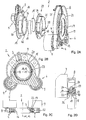
- the Figures 1A to 1C which are jointly described below, show a belt tensioning device 2 according to the invention in a first embodiment.
- the belt tensioning device 2 comprises a base body 3, a first tensioning arm 4 with a first tensioning roller 5, a second tensioning arm 6 with a second tensioning roller 7 and a spring arrangement 8, via which the two tensioning arms 4, 6 are resiliently supported against one another in the direction of rotation.
- the base body 3 can be attached to a stationary component such as an assembly.
- the unit can in principle be any machine that is part of the belt drive, that is to say in particular each of the auxiliary units such as a generator, water pump or the like driven by the main engine of the motor vehicle.
- the base body 3 has a fastening section 9, in particular with three radially outwardly projecting flange projections 10 distributed over the circumference with bores through which screws for fastening to the stationary component can be inserted.
- the belt tensioning device 2 according to the present embodiment is designed in such a way that the fastening section 9 of the base body 3 and the tensioning rollers 5, 7 lie on a common side with respect to the bearings 22, 23, 24 of the tensioning arms 4, 6.
- the base body 3 also has a flange section 11 which adjoins the fastening section 9 radially on the inside and which serves to axially support the second tensioning arm 6.
- the flange section 11 merges radially on the inside into a sleeve section 15 on which the first and second clamping arms 4, 6 are mounted radially.
- an annular disk 21 is fixed as a termination. In the present case, this is done by crimping an end edge of the sleeve section 15, other fastening methods being also conceivable.
- the annular disk 21 forms a support surface for the axial support of the first and second clamping arms 4, 6.
- the annular disk 21, the sleeve section 15 and the flange section 11 form an approximately C-shaped receptacle for the two clamping arms 4, 6 in half longitudinal section.
- the base body 3, the first clamping arm 4 and the second clamping arm 6 are in the present case made of metallic material, such as light metal cast or steel. Steel components have the advantage of high strength with low material usage, so that in particular the clamping arms 4, 6 can be made axially flat.
- the axial length of the two clamping arms 4, 6 is shorter than the axial length in the area of the bearing Length of the spring assembly 8.
- the first clamping arm 4 is mounted pivotably about a first pivot axis A4 by means of the first bearing 22.
- the second clamping arm 6 is mounted pivotably about a second pivot axis A6 by means of the second bearing 24.
- the two bearings 22, 24 are arranged coaxially to one another, that is to say the two pivot axes A4, A6 coincide. In principle, however, it is also conceivable for certain applications that the two pivot axes can be arranged parallel or eccentrically to one another.
- the spring arrangement 8 extending in the circumferential direction around the pivot axes A4, A6 counteracts a relative pivoting movement of the two tensioning arms 4, 6.
- the two tensioning arms 4, 6 can be rotated to a limited extent relative to one another by the interposed spring arrangement 8 and, together with the spring arrangement 8, can be freely rotated around the axes A4, A6 with respect to the base body, that is to say by 360 ° and more. In the mounted state on the stationary component, this free rotatability is only given to the extent that the installation position permits. It is provided that the pivot axes A4, A6 lie within an opening 36 of the base body 3 in the assembled state of the belt tensioning device 2.
- the tensioning arms 4, 6 each have a support section 12, 13 which protrudes radially outward from an annular bearing section 19, 20 of the respective tensioning arm 4, 6.
- An associated tensioning roller 5, 7 is fastened to the carrier section 12, 13 and is rotatably supported by means of corresponding bearings 18, 18 'about axes of rotation A5, A7 parallel to the pivot axes A4, A6.
- the bearing 18 is clamped to the carrier section by means of a screw 14.
- the second tensioning roller 7 is rotatably mounted in an analogous manner on a bearing element of the second tensioning arm 6 and is fastened to the tensioning arm 6 by means of a screw connection 14 ′. Washers 16, 16 'prevent dirt from penetrating into the bearings 18, 18' of the tensioning rollers 5, 7.
- the first clamping arm 4 has a bearing section 19 radially on the inside for rotatable mounting on the base body 3.
- the second clamping arm 5 has a bearing section 20 for rotatable mounting relative to the first bearing section 19 or to the base body 3. It can be seen that the first bearing section 19 and the second bearing section 20 are axially and radially supported against one another.
- the first bearing section 19 is approximately C-shaped in a half longitudinal section and is rotatably mounted on the base body 3 by means of the first bearing 22.
- the second bearing section 20 is approximately rectangular in section and is rotatably seated in the C-shaped first bearing section 19.
- the first bearing 22 comprises a bearing bush 29 which is approximately L-shaped in cross-section and which forms an axial and radial bearing for the first clamping arm 4 with respect to the base body 3, as well as a bearing disk 30 connected to the bearing bush 29, which the first clamping arm 4 in the opposite second slid in the axial direction.
- the L-shaped bearing bush 29 and the bearing washer 30 together form an approximately C-shaped bearing receiving space in which the bearing sections 19, 20 of the clamping arms 4, 5 are received.
- the first bearing 22 is axially supported against the annular disk 21, which is firmly connected to the sleeve section 15.
- the bearing bush 29 sits on the sleeve section 15 of the base body 3 and forms a radial bearing for the C-shaped ring section 19 of the first clamping arm 4.
- the second bearing section 20 is via a second bearing 24, which is designed in particular in the form of a C-shaped sliding ring, mounted axially and radially in the C-shaped first bearing section 19.
- the assembly can take place in such a way that the bearing arrangement consisting of the second bearing 24, second tensioning arm 6, axial bearing 23, first tensioning arm 4 and first bearing 22 is pushed onto the sleeve attachment 15. Then the annular disk 21 is pushed onto the sleeve section 15 and then the end collar of the sleeve section 15 is flanged.
- the tensioning arms 4, 6 lie axially between the fastening section 11 and the annular disk 21.
- the axial length of the base body 3 or the sleeve section 15 is less than three times the axial length of the spiral spring 25, so that the axial installation space is particularly small.
- Ring seals 41, 42 are provided between the components 3, 4, 6, which are rotatable relative to one another, and prevent undesired penetration of dirt into the bearings.
- pretensioning means 17 are provided, which are arranged radially between an outer circumferential surface of the base body 3 and an inner circumferential surface of the bearing bush 29 in order to exert a radial force radially outward in the direction of the annular section 19 which is rotatable relative thereto.
- the bearing bush 29 is, for example, a plastic part, in particular a plastic part made of polyamide, which can be coated with a friction-reducing coating, for example made of polytetrafluoroethylene (PTFE).
- bearing bush 29 is held in a rotationally fixed manner with respect to the sleeve attachment 15 of the base body.
- positive locking means are provided, which in the present case comprise several radial projections 45 on the inner circumferential surface of the bearing bush 29, which can be inserted into corresponding recesses 46 or grooves open on one side, so that the two components are positively connected to one another in the circumferential direction.
- the bearing bush 29 is approximately L-shaped in section and has a flange-shaped section 34 which is axially supported against the flange section 11 of the base body 3 and forms an axial sliding bearing surface for the bearing ring 19 of the first clamping arm 4, as well as a sleeve-shaped section 35 which forms a circumferential sliding bearing surface for the bearing ring 19.
- the bearing bush 29 has a plurality of slots or meander-like web sections 39 distributed over the circumference and extending in the axial direction.
- the slots or meander-like web sections 39 distributed over the circumference enable the bearing bush 29 to be expanded radially. Due to the radial-elastic deformability, the radial forces introduced by the prestressing means 17 are transmitted radially outward to the bearing ring 19 of the first clamping arm 4, so that there is play-free support between the clamping arm 4 and the base body 3.
- the pretensioning means 17 comprise a spring element which extends in the circumferential direction between the sleeve section 15 of the base body 3 and the bearing bush 29 connected to it in a rotationally fixed manner.
- the damping force can be designed as required by appropriate design of the spring element 17, in particular the size and strength.
- a spring element 17 can for example extend over a circumferential extent of between 30 ° and 90 ° with respect to the pivot axis A4.
- the axial length of a spring element 17 can be at least half the axial length of the bearing bush 29.
- the spring element 17 has a curvature in the unassembled state which deviates from the curvature of the support surface of the base body 3. It is provided in particular that the spring element is designed as a straight leaf spring. As a result of the curvature deviating from the support surface, a radial force is exerted by the spring element 17 on the radially elastic bearing bush 29 arranged coaxially therewith. The bearing bush 29 is thereby radially elastically expanded and acts on the annular bearing section 19 of the first tensioning arm 4.
- the biasing means 17, in cooperation with the bearing bushing 29, have a braking or damping effect on the tensioning arm 4 are designated.
- the spring arrangement 8 comprises a bow spring 25 which is supported in the circumferential direction with a first support section 26 on the first tensioning arm 4 and with a second support section 27 on the second tensioning arm.
- the support sections 26, 27 form the ends of the bow spring 25 and can therefore also be referred to as end sections.
- the end sections are arcuate and engage in corresponding circumferential grooves of a support element 31, 32 each connected to the associated clamping arm 4, 6.
- the support elements 31, 32 are each slipped onto the associated carrier element 17 of the tensioning arm 4, 6 from below. Due to the positive engagement of the end sections 26, 27 in the associated support elements 31, 32, the bow spring 25 is fixed in the axial direction and in the circumferential direction.
- the free spring section of the bow spring extends between the two support sections 26, 27 25, in which potential energy is stored when the spring is expanded.
- the bow spring 25 is designed to be mirror-symmetrical with respect to a central plane extending between the two end sections.
- the bow spring 25 has a circumferential extension of less than 360 ° around the first and second pivot axes A4, A6.
- a mean radius of the spring section of the bow spring 25 is larger than a largest radius of the annular bearing sections 19, 20 of the two tensioning arms 4, 6.
- the total axial length of the bow spring 25 is greater than the annular bearing sections 19, 20 of the two tensioning arms 4, 6 , so that an overall axially compact structure is given.
- the bow spring is made of flat material. With flat material is meant in particular that a sheet metal strip with a rectangular cross section is used as the starting material.
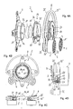
- FIG. 2A to 2D A slightly modified second embodiment of the belt tensioning device is shown, which largely corresponds to the belt tensioning device from FIG. 1, to the description of which reference is made in terms of the similarities. The same or modified details are provided with the same reference symbols as in FIG Figure 1 .
- FIG. 3A to 3C a belt tensioning device 2 according to the invention is shown in a further embodiment.
- the present embodiment largely corresponds to the belt tensioning device from Figure 1 , to the description of which reference is made in terms of the similarities.
- the same or corresponding details are provided with the same reference symbols as in FIG Figure 1 .
- a first difference of the present embodiment is that the belt tensioning device 2 is designed in such a way that the bearing 22, 24 of the tensioning arms 4, 6 on the base body 3 is axially between the fastening section 9 of the base body 3 on the one hand and a center plane of the tensioning rollers 5, 7 or the Belt is arranged on the other hand.
- the belt plane is defined as the plane that is spanned by the middle of the belt in the assembled state.
- the spring arrangement 8 in the present case comprises two bow springs 25, 25 'which are identical to one another designed and arranged parallel to each other.
- the two bow springs 25, 25 ' can be connected to one another by means of one or more fastening elements while forming an axial gap.
- the end sections 26, 27; 26 ', 27' are received in support elements 31, 32, which each have two arc-shaped grooves.
- the support elements 31, 32 are as in the embodiment according to FIGS Figures 1 or 2 connected to the respective clamping arm 4, 6.
- the two bow springs 25, 25 ' are in the present case made of round material, that is, they have a round cross-section over their length.
- FIG. 4A to 4D a further embodiment of the belt tensioning device 2 according to the invention is shown. This largely corresponds to the belt tensioning device Figure 3 , to the description of which reference is made in terms of the similarities. The same or corresponding details are provided with the same reference symbols as in FIG Figure 3 .
Description
Die Erfindung betrifft eine Riemenspannvorrichtung für einen Riementrieb mit riemengetriebenen Starter-Generator. Ein Riementrieb umfasst üblicherweise einen endlosen Riemen und zumindest zwei Riemenscheiben, von denen eine als Antrieb und eine als Abtrieb des Riementriebs fungieren kann. Derartige Riementriebe kommen insbesondere an Verbrennungsmotoren eines Kraftfahrzeugs zum Antreiben von Nebenaggregaten zum Einsatz, wobei eine erste Riemenscheibe auf der Kurbelwelle des Verbrennungsmotors sitzt und den Riemen antreibt. Weitere Riemenscheiben sind den Nebenaggregaten zugeordnet, wie beispielsweise Wasserpumpe, Lichtmaschine oder Klimaanlagenkompressor, und werden vom Riemenantrieb drehend angetrieben. Bei herkömmlichen Riementrieben sind die Nebenaggregate als Verbraucher ausgelegt, das heißt sie werden von der Riemenscheibe der Kurbelwelle über den Riemen angetrieben. Dabei ist zwischen der Kurbelwelle und dem in Umlaufrichtung des Riemens benachbarten Aggregat, in der Regel der Generator, das Lostrum ausgebildet. Um hier eine ausreichende Umschlingung des Riemens um die Riemenscheibe zu gewährleisten, wird der Riemen mittels einer Spannrolle der Riemenspannvorrichtung vorgespannt.The invention relates to a belt tensioning device for a belt drive with a belt-driven starter generator. A belt drive usually comprises an endless belt and at least two belt pulleys, one of which can function as the drive and one as the output of the belt drive. Belt drives of this type are used in particular on internal combustion engines of a motor vehicle to drive auxiliary units, a first belt pulley sitting on the crankshaft of the internal combustion engine and driving the belt. Additional pulleys are assigned to the auxiliary units, such as the water pump, alternator or air conditioning compressor, and are driven in rotation by the belt drive. In conventional belt drives, the ancillary units are designed as consumers, that is, they are driven by the belt pulley of the crankshaft via the belt. The slack drum is formed between the crankshaft and the unit, usually the generator, which is adjacent in the direction of rotation of the belt. In order to ensure a sufficient looping of the belt around the pulley, the belt is pretensioned by means of a tensioning roller of the belt tensioning device.
Aus der
Aus der
Aus der
Der vorliegenden Erfindung liegt die Aufgabe zugrunde, eine Riemenspannvorrichtung vorzuschlagen, die geringe Lagetoleranzen und gute Dämpfungseigenschaften aufweist.The present invention is based on the object of proposing a belt tensioning device which has low positional tolerances and good damping properties.
Zur Lösung wird eine Riemenspannvorrichtung vorgeschlagen, die die Merkmale des Anspruchs 1 umfasst.To solve this, a belt tensioning device is proposed which comprises the features of claim 1.
Ein Vorteil dieser Riemenspannvorrichtung ist, dass die radial wirkenden Vorspannmittel keinen nachteiligen Einfluss auf die Lagerung und Führung der am Grundkörper schwenkbar gelagerten Spannarme haben. Die Anordnung zwischen Grundkörper, Lagerbuchse und hierauf schwenkbar gelagertem Spannarm ist aufgrund der radialen Vorspannkraft radial spielfrei. Insgesamt werden auf diese Weise gute Dämpfungseigenschaften bei gleichzeitig geringen Lagetoleranzen für die Spannarme erreicht. Durch geeignete Auswahl und Ausgestaltung der Vorspannmittel können die gewünschten Dämpfungseigenschaften der Riemenspannvorrichtung nach Bedarf angepasst werden, insbesondere auf die im Start-, Boost- beziehungsweise Rekuperationsbetrieb gewünschten Eigenschaften.One advantage of this belt tensioning device is that the radially acting pretensioning means have no disadvantageous influence on the mounting and guidance of the clamping arms pivotably mounted on the base body. The arrangement between the base body, the bearing bush and the clamping arm pivotably mounted thereon is free of radial play due to the radial prestressing force. Overall, good damping properties with low positional tolerances for the clamping arms are achieved in this way. By suitable selection and design of the pretensioning means, the desired damping properties of the belt tensioning device can be adapted as required, in particular to the properties desired in the start, boost or recuperation operation.
Der Aufbau und das Wirkprinzip sind allgemein so, dass die drei Bauteile Grundkörper, Lagerbuchse und Spannarm koaxial ineinander angeordnet sind, wobei die Lagerbuchse mit einem von den beiden Teilen, Grundkörper oder Spannarm, drehfest verbunden und gegenüber dem andern der genannten Teile, Spannarm oder Grundkörper, drehbar ist. Die Vorspannmittel sind radial zwischen den beiden drehfest miteinander verbundenen Bauteilen wirksam angeordnet und beaufschlagen die radial-elastische Lagerbuchse radial in Richtung zum relativ hierzu drehbaren Bauteil.The structure and the operating principle are generally such that the three components base body, bearing bushing and clamping arm are arranged coaxially one inside the other, with the bearing bushing non-rotatably connected to one of the two parts, base body or clamping arm, and with respect to the other of the named parts, clamping arm or base body , is rotatable. The pretensioning means are effectively arranged radially between the two components that are connected to one another in a rotationally fixed manner and act on the radially elastic bearing bushing radially in the direction of the component that is rotatable relative thereto.
Die Lagerbuchse kann mehrere über den Umfang verteilte, sich in axiale Richtung erstreckende Schlitze beziehungsweise mäanderartige Stegabschnitte aufweisen. Die über den Umfang verteilten Schlitze beziehungsweise mäanderartigen Stegabschnitte ermöglichen, dass die Lagerbuchse radial aufgeweitet oder verkleinert werden kann. Durch die radial-elastische Verformbarkeit werden die von den Vorspannmitteln eingeleiteten Radialkräfte in radiale Richtung auf das hierzu drehbare Bauteil übertragen, so dass eine spielfreie Lagerung zwischen Spannarm und Grundkörper hergestellt ist.The bearing bushing can have a plurality of slots or meander-like web sections distributed over the circumference and extending in the axial direction. The slots or meander-like web sections distributed over the circumference make it possible for the bearing bush to be radially expanded or reduced. As a result of the radial-elastic deformability, the radial forces introduced by the prestressing means are transmitted in the radial direction to the component that can be rotated for this purpose, so that a backlash-free mounting between the clamping arm and the base body is established.
Die Lagerbuchse kann beispielsweise ein Kunststoffteil sein, insbesondere ein aus Polyamid hergestelltes Kunststoffteil. Die Lagerbuchse kann mit einer reibungsmindernden Beschichtung, beispielsweise aus Polytetrafluoräthylen (PTFE) beschichtet sein.The bearing bushing can for example be a plastic part, in particular a plastic part made of polyamide. The bearing bush can be coated with a friction-reducing coating, for example made of polytetrafluoroethylene (PTFE).
Der Grundkörper kann beispielsweise aus einem metallischen Werkstoff, beispielsweise als Leichtmetallgussbauteil oder in Form eines Blechformteils aus Stahlblech hergestellt sein, wobei die Herstellung aus Kunststoff, insbesondere faserverstärkten Kunststoff ebenso denkbar ist.The base body can for example be made of a metallic material, for example as a light metal cast component or in the form of a sheet metal part made of sheet steel, the production of plastic, in particular fiber-reinforced plastic, also being conceivable.
Der erste und/oder zweite Spannarm können aus einem metallischen Werkstoff, insbesondere einem Stahlwerkstoff oder Leichtmetallguss hergestellt sein.The first and / or second clamping arm can be made from a metallic material, in particular a steel material or light metal casting.
Die Vorspannmittel können prinzipiell beliebig gestaltet sein. Es sind alle Elemente denkbar, mit denen eine radial wirkende Vorspannkraft auf die Lagerbuchse erzeugt werden kann. Nach einer möglichen Ausführungsform umfassen die Vorspannmittel zumindest ein Federelement, das sich in Umfangsrichtung zwischen der Lagerbuchse und dem hiermit drehfest verbundenen Teil erstreckt, insbesondere um eine Umfangserstreckung von mindestens 30° und/oder höchstens 90°. Die Umfangserstreckung eines Federelements kann beispielsweise auch mindestens 10° und/oder höchstens 30° in Bezug um die Schwenkachse betragen. Das Federelement kann insbesondere als Blattfeder gestaltet sein.The pretensioning means can in principle be designed as desired. All elements are conceivable with which a radially acting prestressing force can be generated on the bearing bush. According to one possible embodiment, the pretensioning means comprise at least one spring element which extends in the circumferential direction between the bearing bush and the part non-rotatably connected to it, in particular around a circumferential extent of at least 30 ° and / or at most 90 °. The circumferential extension of a spring element can, for example, also be at least 10 ° and / or at most 30 ° in relation to the pivot axis. The spring element can in particular be designed as a leaf spring.
Durch entsprechende Auswahl der Anzahl, Stärke und/oder Anordnung der Federelemente kann die Dämpfungskraft bedarfsgerecht ausgelegt werden. Bei größerer gewünschter Dämpfung können zwei oder mehr Federelement über den Umfang verteilt angeordnet werden. Vorzugsweise werden die Federelemente dabei so angeordnet, dass die von den Federelementen generierten Radialkräfte einander zumindest teilweise aufheben. Ein günstiger Kompromiss hinsichtlich Fertigungs- und Montageaufwand einerseits und guter radialer Vorspannung andererseits ist die Verwendung von zwei Federelementen, die einander vorzugsweise zumindest etwa diametral gegenüberliegend angeordnet sind, beispielsweise um 180° ± 10°. Bei Verwendung mehrerer Federelemente sind diese vorzugsweise untereinander gleich gestaltet. Die Federelemente können beispielsweise in Form von Blattfedern oder Wellfedern gestaltet sein, wobei prinzipiell auch andere elastische Elemente wie Gummielemente denkbar sind.By appropriate selection of the number, strength and / or arrangement of the spring elements, the damping force can be designed as required. If greater damping is required, two or more spring elements can be arranged distributed over the circumference. The spring elements are preferably arranged in such a way that the radial forces generated by the spring elements at least partially cancel one another. A favorable compromise with regard to manufacturing and assembly costs on the one hand and good radial preload on the other hand is the use of two spring elements, which are preferably arranged at least approximately diametrically opposite one another, for example by 180 ° ± 10 °. When using multiple These spring elements are preferably designed the same as one another. The spring elements can be designed, for example, in the form of leaf springs or corrugated springs, with other elastic elements such as rubber elements also being conceivable in principle.
Das mindestens eine Federelement kann in unmontiertem Zustand eine Krümmung aufweisen, die von der Krümmung der Stützfläche der Lagerbuchse beziehungsweise des hiermit drehfest verbundenen Teils (Spannarm oder Grundkörper) abweicht. Nach einer ersten Möglichkeit kann das Federelement eine größere Krümmung aufweisen als die Stützfläche, wobei insbesondere auch eine gerade Ausgestaltung mit umfasst ist. Alternativ hierzu kann das Federelement auch eine kleinere Krümmung aufweisen als die Stützfläche. Durch die von der Stützfläche abweichenden Krümmung wird von dem Federelement eine Radialkraft auf die in Umfangsrichtung radial-elastische Lagerbuchse ausgeübt. Die Lagerbuchse wird dadurch radial elastisch aufgeweitet und beaufschlagt das relativ hierzu drehbare Teil (Spannarm oder Grundkörper) in radiale Richtung und wirkt damit wie eine Bremse.In the unassembled state, the at least one spring element can have a curvature which deviates from the curvature of the support surface of the bearing bush or of the part connected to it in a rotationally fixed manner (clamping arm or base body). According to a first possibility, the spring element can have a greater curvature than the support surface, a straight configuration also being included in particular. Alternatively, the spring element can also have a smaller curvature than the support surface. Due to the curvature deviating from the support surface, a radial force is exerted by the spring element on the bearing bush, which is radially elastic in the circumferential direction. As a result, the bearing bush is elastically expanded radially and acts on the part (clamping arm or base body) that is rotatable relative thereto in the radial direction and thus acts like a brake.
Für eine möglichst hohe und gleichmäßige Dämpfungskraft ist es günstig, wenn die Vorspannmittel eine möglichst große Kontaktfläche haben. Hierfür können die Vorspannmittel eine axiale Länge aufweisen, die mindestens der halben axialen Länge der Lagerbuchse entspricht.For a damping force that is as high and uniform as possible, it is advantageous if the pretensioning means have the largest possible contact surface. For this purpose, the preloading means can have an axial length which corresponds to at least half the axial length of the bearing bush.
Wie oben beschrieben, ist die Lagerbuchse mit einem der Teile, Grundkörper oder Spannarm, drehfest verbunden. Zur drehfesten Verbindung können insbesondere Formschlussmittel zwischen der Lagerbuchse und dem hiermit drehfest verbundenen Bauteil vorgesehen sein, die formschlüssig ineinander greifen. Die Formschlussmittel können beispielsweise einen sich in axiale Richtung erstreckenden Steg aufweisen, der in eine entsprechende sich in axiale Richtung erstreckende Nut formschlüssig eingreift, so dass die Lagerbuchse gegenüber dem Anschlussbauteil verdrehgesichert ist.As described above, the bearing bush is non-rotatably connected to one of the parts, the base body or the clamping arm. For the non-rotatable connection, in particular form-locking means can be provided between the bearing bushing and the component non-rotatably connected to it, which interlock with one another in a form-locking manner. The form-locking means can, for example, have a web extending in the axial direction which positively engages in a corresponding groove extending in the axial direction, so that the bearing bush is secured against rotation with respect to the connecting component.
Damit das zumindest eine Federelement zuverlässig gehalten ist, kann in der Umfangsfläche des mit der Lagerbuchse drehfest verbundenen Teils je Federelement eineSo that the at least one spring element is held reliably, one spring element can be installed in the circumferential surface of the part connected in a rotationally fixed manner to the bearing bush
Ausnehmung vorgesehen sein, in der jeweils ein Federelement aufgenommen ist. Dabei ist insbesondere vorgesehen, dass die Federelemente in Umfangsrichtung an Seitenflächen der Ausnehmung abgestützt sind. Nach einer möglichen ersten Ausführungsform ist die Lagerbuchse mit dem Grundkörper drehfest verbunden ist, und der erste Spannarm gegenüber der Lagerbuchse drehbar. In diesem Fall ist das zumindest eine Federelement am Grundkörper radial abgestützt und beaufschlagt die Lagerbuchse in Richtung Lagerring des Spannarms. Nach einer hierzu alternativen zweiten Ausführungsform ist die Lagerbuchse mit dem Spannarm drehfest verbunden ist, und die Baueinheit aus Lagerring und Spannarm ist gegenüber dem Grundkörper drehbar. In diesem Fall ist das zumindest eine Federelement am Spannarm radial abgestützt und beaufschlagt die Lagerbuchse in Richtung Hülsenansatz des Grundkörpers.Be provided recess in each of which a spring element is received. It is provided in particular that the spring elements are supported in the circumferential direction on side surfaces of the recess. According to a possible first embodiment, the bearing bush is non-rotatably connected to the base body, and the first clamping arm is rotatable with respect to the bearing bush. In this case, the at least one spring element is radially supported on the base body and acts on the bearing bush in the direction of the bearing ring of the tensioning arm. According to a second embodiment alternative to this, the bearing bushing is connected to the tensioning arm in a rotationally fixed manner, and the structural unit comprising the bearing ring and tensioning arm can be rotated relative to the base body. In this case, the at least one spring element is supported radially on the tensioning arm and acts on the bearing bush in the direction of the sleeve attachment of the base body.
Nach einer Ausführungsform weist die Federanordnung zumindest eine Bügelfeder auf, die im Einbauzustand eine Umfangserstreckung um die Schwenkachsen der Spannarme von weniger als 360°, insbesondere von weniger als 330° aufweist. Die Bügelfeder hat an ihren Enden jeweils einen Stützabschnitt, mit dem die Feder an dem jeweiligen Spannarm in Umfangsrichtung abgestützt ist, um die beiden Spannarme gegeneinander zu beaufschlagen. Die Stützabschnitte können bogenförmig gestaltet sein und in einer entsprechenden Umfangsnut an dem Spannarm einsitzen, so dass die Feder in axialer Richtung und in Umfangsrichtung durch die Aufnahme in den beiden Umfangsnuten der beiden Spannarme fixiert ist. Zwischen den beiden Stützabschnitten liegt ein Federabschnitt, in dem beim elastischen Aufweiten der Feder potentielle Energie gespeichert wird. Der Federabschnitt, welcher auch als Bügelabschnitt bezeichnet werden kann, wird beim elastischen Aufweiten insbesondere auf Biegung beansprucht. Die zumindest eine Bügelfeder kann aus Runddraht oder Rechteckdraht hergestellt sein. Es können ein oder zwei Federn vorgesehen sein.According to one embodiment, the spring arrangement has at least one bow spring which, in the installed state, has a circumferential extent around the pivot axes of the clamping arms of less than 360 °, in particular of less than 330 °. At each of its ends, the bow spring has a support section with which the spring is supported in the circumferential direction on the respective tensioning arm in order to act on the two tensioning arms against one another. The support sections can be arcuate and sit in a corresponding circumferential groove on the tensioning arm so that the spring is fixed in the axial direction and in the circumferential direction by the receptacle in the two circumferential grooves of the two tensioning arms. Between the two support sections there is a spring section in which potential energy is stored when the spring is elastically expanded. The spring section, which can also be referred to as a bracket section, is particularly stressed in terms of bending during elastic expansion. The at least one bow spring can be made from round wire or rectangular wire. One or two springs can be provided.
Der Grundkörper kann einen Befestigungsabschnitt zum Befestigen der Riemenspannvorrichtung an einem ortsfesten Bauteil, beispielsweise dem Aggregat oder Motorgehäuse aufweisen. Der Befestigungsabschnitt kann flanschartig von dem Hülsen- oder Ringabschnitt, durch den die Antriebswelle geführt ist, abstehen. Günstig ist es, wenn der Befestigungsabschnitt mehrere Befestigungspunkte hat, an denen der Grundkörper mit dem Aggregat verbunden werden kann.The base body can have a fastening section for fastening the belt tensioning device to a stationary component, for example the unit or the motor housing. The fastening section can protrude in the manner of a flange from the sleeve or ring section through which the drive shaft is guided. It is favorable if the fastening section has several fastening points at which the base body can be connected to the unit.
Bevorzugte Ausführungsbeispiele werden nachstehend anhand der Zeichnungsfiguren erläutert. Hierin zeigt
- Figur 1
- eine erfindungsgemäße Riemenspannvorrichtung in einer ersten Ausführungsform mit einer Biegefeder
- A) in perspektivischer Explosionsdarstellung;
- B) im Querschnitt;
- C) im Halblängsschnitt;
Figur 2- eine erfindungsgemäße Riemenspannvorrichtung in einer abgewandelten zweiten Ausführungsform mit einer Biegefeder
- A) in perspektivischer Explosionsdarstellung;
- B) im Querschnitt;
- C) im Längsschnitt;
- D) im Halblängsschnitt, in vergrößerter Darstellung;
Figur 3- eine erfindungsgemäße Riemenspannvorrichtung in einer dritten Ausführungsform mit zwei Biegefedern
- A) in perspektivischer Explosionsdarstellung;
- B) im Querschnitt durch eine Schnittebene zwischen den Biegefedern;
- C) im Längsschnitt;
Figur 4- eine erfindungsgemäße Riemenspannvorrichtung in einer abgewandelten zweiten Ausführungsform mit einer Biegefeder
- A) in perspektivischer Explosionsdarstellung;
- B) im Querschnitt durch eine Schnittebene zwischen den Biegefedern;
- C) im Halblängsschnitt;
- D) im Halblängsschnitt, in vergrößerter Darstellung.
- Figure 1
- a belt tensioning device according to the invention in a first embodiment with a spiral spring
- A) in a perspective exploded view;
- B) in cross section;
- C) in half longitudinal section;
- Figure 2
- a belt tensioning device according to the invention in a modified second embodiment with a spiral spring
- A) in a perspective exploded view;
- B) in cross section;
- C) in longitudinal section;
- D) in half longitudinal section, in an enlarged view;
- Figure 3
- a belt tensioning device according to the invention in a third embodiment with two spiral springs
- A) in a perspective exploded view;
- B) in cross section through a cutting plane between the spiral springs;
- C) in longitudinal section;
- Figure 4
- a belt tensioning device according to the invention in a modified second embodiment with a spiral spring
- A) in a perspective exploded view;
- B) in cross section through a cutting plane between the spiral springs;
- C) in half longitudinal section;
- D) in half longitudinal section, enlarged view.
Die
Der Grundkörper 3 kann an einem ortsfesten Bauteil wie einem Aggregat befestigt werden. Das Aggregat kann prinzipiell jede Maschine sein, die Teil des Riementriebes ist, das heißt insbesondere jedes der vom Hauptmotor des Kraftfahrzeugs angetriebenen Nebenaggregate wie Generator, Wasserpumpe oder dergleichen. Zur Verbindung mit dem ortsfesten Bauteil hat der Grundkörper 3 einen Befestigungsabschnitt 9, mit insbesondere drei über den Umfang verteilten nach radial außen vorstehende Flanschvorsprüngen 10 mit Bohrungen, durch die Schrauben zur Befestigung an dem ortsfesten Bauteil durchgesteckt werden können. Die Riemenspannvorrichtung 2 gemäß der vorliegenden Ausführungsform ist so gestaltet, dass der Befestigungsabschnitt 9 des Grundkörpers 3, und die Spannrollen 5, 7 auf einer gemeinsamen Seite in Bezug auf die Lagerung 22, 23, 24 der Spannarme 4, 6 liegen.The
Der Grundkörper 3 hat ferner einen radial innen an den Befestigungsabschnitt 9 anschließenden Flanschabschnitt 11, der zur axialen Abstützung des zweiten Spannarms 6 dient. Der Flanschabschnitt 11 geht radial innen in einen Hülsenabschnitt 15 über, an dem der erste beziehungsweise zweite Spannarm 4, 6 radial gelagert sind. Am freien Ende des Hülsenabschnitts 15 ist eine Ringscheibe 21 als Abschluss fixiert. Dies erfolgt vorliegend durch Umbördeln eines endseitigen Randes des Hülsenabschnitts 15, wobei andere Befestigungsmethoden ebenso denkbar sind. Die Ringscheibe 21 bildet eine Stützfläche zur axialen Abstützung des ersten beziehungsweise zweiten Spannarms 4, 6. Insgesamt bilden die Ringscheibe 21, der Hülsenabschnitt 15 und der Flanschabschnitt 11 eine im Halblängsschnitt etwa C-förmige Aufnahme für die beiden Spannarme 4, 6.The
Der Grundkörper 3, der erste Spannarm 4 und der zweite Spannarm 6 sind vorliegend aus metallischen Material, wie Leichtmetallguss oder aus Stahl ausgeführt. Stahlbauteile haben den Vorteil einer hohen Festigkeit bei niedrigem Materialeinsatz, so dass insbesondere die Spannarme 4, 6 axial flach ausgeführt werden können. Die axiale Länge der beiden Spannarme 4, 6 ist im Bereich der Lagerung kürzer als die axiale Länge der Federanordnung 8.The
Der erste Spannarm 4 ist mittels des ersten Lagers 22 um eine erste Schwenkachse A4 schwenkbar gelagert. Der zweite Spannarm 6 ist mittels des zweiten Lagers 24 um eine zweite Schwenkachse A6 schwenkbar gelagert. Vorliegend sind die beiden Lager 22, 24 koaxial zueinander angeordnet, das heißt die beiden Schwenkachsen A4, A6 fallen zusammen. Grundsätzlich ist es jedoch für bestimmte Anwendungen auch denkbar, dass die beiden Schwenkachsen parallel beziehungsweise exzentrisch zueinander angeordnet sein können. Die sich in Umfangsrichtung um die Schwenkachsen A4, A6 erstreckende Federanordnung 8 wirkt einer relativen Schwenkbewegung der beiden Spannarme 4, 6 entgegen. Die beiden Spannarme 4, 6 sind durch die zwischengeschaltete Federanordnung 8 relativ zueinander begrenzt drehbar und zusammen mit der Federanordnung 8 gegenüber dem Grundkörper um die Achsen A4, A6 frei drehbar, das heißt um 360° und mehr. Im an das ortsfeste Bauteil montierten Zustand ist diese freie Drehbarkeit nur insoweit gegeben wie es die Einbaulage zulässt. Es ist vorgesehen, dass die Schwenkachsen A4, A6 in montiertem Zustand der Riemenspannvorrichtung 2 innerhalb einer Öffnung 36 des Grundkörpers 3 liegen.The
Die Spannarme 4, 6 haben jeweils einen Trägerabschnitt 12, 13, der von einem ringförmigen Lagerabschnitt 19, 20 des jeweiligen Spannarms 4, 6 nach radial außen vorsteht. An dem Trägerabschnitt 12, 13 ist jeweils eine zugehörige Spannrolle 5, 7 befestigt und mittels entsprechender Lager 18, 18' um zu den Schwenkachsen A4, A6 parallele Drehachsen A5, A7 drehbar gelagert. Das Lager 18 ist mittels einer Schraube 14 mit dem Trägerabschnitt verspannt. Die zweite Spannrolle 7 ist in analoger Form auf einem Lagerelement des zweiten Spannarms 6 drehbar gelagert und mittels einer Schraubverbindung 14' an dem Spannarm 6 befestigt. Scheiben 16, 16' verhindern das Eindringen von Schmutz in die Lager 18, 18' der Spannrollen 5, 7.The tensioning
Im Folgenden wird näher auf die Lageranordnung der Riemenspannvorrichtung eingegangen, welche als Detail insbesondere in
Das erste Lager 22 umfasst eine im Querschnitt etwa L-förmigen Lagerbuchse 29, die eine axiale und radiale Lagerung für den ersten Spannarm 4 gegenüber dem Grundkörper 3 bildet, sowie eine mit der Lagerbuchse 29 verbundene Lagerscheibe 30, die den ersten Spannarm 4 in entgegengesetzter zweiter axialer Richtung gleitend lagert. Die L-förmige Lagerbuchse 29 und die Lagerscheibe 30 bilden gemeinsam einen etwa C-förmigen Lageraufnahmeraum, in dem die Lagerabschnitte 19, 20 der Spannarme 4, 5 aufgenommen sind. Das erste Lager 22 ist axial gegen die Ringscheibe 21 abgestützt, welche mit dem Hülsenabschnitt 15 fest verbunden ist. Die Lagerbuchse 29 sitzt auf dem Hülsenabschnitt 15 des Grundkörpers 3 und bildet ein Radiallager für den C-förmigen Ringabschnitt 19 des ersten Spannarms 4. Der zweite Lagerabschnitt 20 ist über ein zweites Lager 24, das insbesondere in Form eines C-förmigen Gleitrings gestaltet ist, in dem C-förmigen ersten Lagerabschnitt 19 axial und radial gelagert.The
Die Montage kann derart erfolgen, dass die Lageranordnung bestehend aus zweitem Lager 24, zweitem Spannarm 6, Axiallager 23, erstem Spannarm 4 und erstem Lager 22 auf den Hülsenansatz 15 aufgeschoben wird. Dann wird die Ringscheibe 21 auf den Hülsenabschnitt 15 aufgeschoben und anschließend der endseitige Bund des Hülsenabschnitts 15 umgebördelt. In montiertem Zustand liegen die Spannarme 4, 6 axial zwischen dem Befestigungsabschnitt 11 und der Ringscheibe 21. Die axiale Länge des Grundkörpers 3 beziehungsweise des Hülsenabschnitts 15 ist kleiner als die Dreifache axiale Länge der Biegefeder 25, so dass der axiale Bauraum besonders gering ist. Zwischen den jeweils zueinander drehbaren Bauteilen 3, 4, 6, sind Ringdichtungen 41, 42 vorgesehen, welche ein ungewünschtes Eindringen von Schmutz in die Lager verhindern.The assembly can take place in such a way that the bearing arrangement consisting of the
Eine Besonderheit der vorliegenden Ausführungsform ist, dass Vorspannmittel 17 vorgesehen sind, die radial zwischen einer Außenumfangsfläche des Grundkörpers 3 und einer Innenumfangsfläche der Lagerbuchse 29 angeordnet sind, um eine Radialkraft nach radial außen in Richtung dem relativ hierzu drehbaren Ringabschnitt 19 auszuüben. Die Lagerbuchse 29 ist beispielsweise ein Kunststoffteil, insbesondere ein aus Polyamid hergestelltes Kunststoffteil, das mit einer reibungsmindernden Beschichtung, beispielsweise aus Polytetrafluorethylen (PTFE) beschichtet sein kann.A special feature of the present embodiment is that pretensioning means 17 are provided, which are arranged radially between an outer circumferential surface of the
Die Lagerbuchse 29 ist drehfest gegenüber dem Hülsenansatz 15 des Grundkörpers gehalten. Zur drehfesten Verbindung sind Formschlussmittel vorgesehen, die vorliegend mehrere radiale Vorsprünge 45 an der Innenumfangsfläche der Lagerbuchse 29 umfassen, die in entsprechende einseitig offene Ausnehmungen 46 beziehungsweise Nuten eingeschoben werden können, so dass die beiden Bauteile in Umfangsrichtung formschlüssig miteinander verbunden sind. Die Lagerbuchse 29 ist im Schnitt etwa L-förmig gestaltet und hat einen flanschförmigen Abschnitt 34, der gegen den Flanschabschnitt 11 des Grundkörpers 3 axial abgestützt ist und eine axiale Gleitlagerfläche für den Lagerring 19 des ersten Spannarms 4 bildet, sowie einen hülsenförmigen Abschnitt 35, der eine Umfangsgleitlagerfläche für den Lagerring 19 bildet.The bearing
Es ist insbesondere in
Die Vorspannmittel 17 umfassen bei der vorliegenden Ausführungsform ein Federelement, das sich in Umfangsrichtung zwischen dem Hülsenabschnitt 15 des Grundkörpers 3 und hiermit drehfest verbundenen der Lagerbuchse 29 erstreckt. Durch entsprechende Ausgestaltung des Federelements 17, insbesondere Größe und Stärke kann die Dämpfungskraft bedarfsgerecht ausgelegt werden. Ein Federelement 17 kann sich beispielsweise über eine Umfangserstreckung von zwischen 30° und 90° in Bezug auf die Schwenkachse A4 erstrecken. Die axiale Länge eines Federelements 17 kann mindestens die halben axiale Länge der Lagerbuchse 29 betragen.In the present embodiment, the pretensioning means 17 comprise a spring element which extends in the circumferential direction between the
Anders als dargestellt, hat das Federelement 17 in unmontiertem Zustand eine Krümmung, die von der Krümmung der Stützfläche des Grundkörpers 3 abweicht. Es ist insbesondere vorgesehen, dass das Federelement als gerade Blattfeder gestaltet ist. Durch die von der Stützfläche abweichende Krümmung wird von dem Federelement 17 eine Radialkraft auf die in koaxial hierzu angeordnete radial-elastische Lagerbuchse 29 ausgeübt. Die Lagerbuchse 29 wird dadurch radial elastisch aufgeweitet und beaufschlagt den ringförmigen Lagerabschnitt 19 ersten Spannarms 4. Insofern haben die Vorspannmittel 17 im Zusammenwirken mit der Lagerbuchse 29 eine bremsende beziehungsweise dämpfende Wirkung auf den Spannarm 4. Vorspannmittel 17 und Lagerbuchse 29 können daher auch gemeinsam als Dämpfungsmittel bezeichnet werden.In contrast to what is shown, the
Es ist insbesondere in
Die Federanordnung 8 umfasst eine Bügelfeder 25, die mit einem ersten Stützabschnitt 26 an dem ersten Spannarm 4 und mit einem zweiten Stützabschnitt 27 an dem zweiten Spannarm in Umfangsrichtung abgestützt ist. Die Stützabschnitte 26, 27 bilden die Enden der Bügelfeder 25 und können daher auch als Endabschnitte bezeichnet werden. Die Endabschnitte sind bogenförmig gestaltet und greifen in entsprechende Umfangsnuten eines jeweils mit dem zugehörigen Spannarm 4, 6 verbundenen Stützelements 31, 32 ein. Die Stützelemente 31, 32 sind jeweils von unten auf das zugehörige Trägerelement 17 des Spannarms 4, 6 aufgesteckt. Durch den formschlüssigen Eingriff der Endabschnitte 26, 27 in den zugehörigen Stützelementen 31, 32 wird die Bügelfeder 25 in axialer Richtung und in Umfangsrichtung fixiert. Zwischen den beiden Stützabschnitten 26, 27 erstreckt sich der freie Federabschnitt der Bügelfeder 25, in dem beim Aufweiten der Feder potentielle Energie gespeichert wird. Die Bügelfeder 25 ist in Bezug auf eine sich zwischen den beiden Endabschnitte erstreckende Mittelebene spiegelsymmetrisch gestaltet.The
Die Bügelfeder 25 hat eine Umfangserstreckung von weniger als 360° um die erste und zweite Schwenkachse A4, A6. Dabei ist ein mittlerer Radius des Federabschnitts der Bügelfeder 25 größer ist als ein größter Radius der ringförmigen Lagerabschnitte 19, 20 der beiden Spannarme 4, 6. Die axiale Gesamtlänge der Bügelfeder 25 ist größer ist als ringförmigen Lagerabschnitte 19, 20 der beiden Spannarme 4, 6, so dass ein insgesamt axial kompakter Aufbau gegeben ist. Die Bügelfeder ist bei der vorliegenden Ausführungsform aus Flachmaterial hergestellt. Mit Flachmaterial ist insbesondere gemeint, dass als Ausgangsmaterial ein Blechstreifen mit einem rechteckigen Querschnitt verwendet wird.The
Die Bügelfeder 25 steht im Einbauzustand unter starker Druckvorspannung in Umfangsrichtung, das heißt die Feder ist gegenüber ihrem entspannten Zustand aufgeweitet, so dass die Feder die beiden Spannarme 4, 6 in Richtung aufeinander zu beaufschlagt. Zum (vorübergehenden) Fixieren der vorgespannten Stellung werden die Spannarme 4, 6 entgegen der Vorspannkraft der Feder voneinander weg bewegt und ein Sicherungsstift 33 in eine erste Bohrung im ersten Spannarm 4 eingesteckt, der gegen einen radialen Vorsprung am zweiten Spannarm 6 in Umfangsrichtung abgestützt ist. Nach dem Montieren der Riemenspannvorrichtung 2 an einem Aggregat und Auflegen des Riemens wird der Sicherungsstift 33 gezogen, so dass die Spannarme 4, 6 von der Bügelfeder 25 in Umfangsrichtung aufeinander zu beaufschlagt werden und die Spannrollen 5, 7 den Riemen vorspannen.In the installed state, the
Der Grundkörper 3 beziehungsweise die Riemenspannvorrichtung 2 sind derart gestaltet, dass - in montiertem Zustand der Riemenspannvorrichtung 2 an ein Aggregat - die Schwenkachsen A4, A6 der Spannarme 4, 6 innerhalb des Außendurchmessers der Antriebswelle, insbesondere im Wesentlichen koaxial zur Antriebsdrehachse, angeordnet ist.The
In den
Im Unterschied zur Ausführung nach
In den
Ein erster Unterscheid der vorliegenden Ausführungsform besteht darin, dass die Riemenspannvorrichtung 2 so gestaltet ist, dass die Lagerung 22, 24 der Spannarme 4, 6 am Grundkörper 3 axial zwischen dem Befestigungsabschnitt 9 des Grundkörpers 3 einerseits und einer Mittelebene der Spannrollen 5, 7 beziehungsweise des Riemens andererseits angeordnet ist. Als Riemenebene ist die Ebene definiert, welche durch die Riemenmitte in montiertem Zustand aufgespannt wird.A first difference of the present embodiment is that the
Ein weiterer Unterschied betrifft die Ausgestaltung der Federanordnung 8. Die Federanordnung 8 umfasst vorliegend zwei Bügelfedern 25, 25', die untereinander gleich gestaltet und parallel zueinander angeordnet sind. Die beiden Bügelfedern 25, 25' können mittels eines oder mehreren Befestigungselementen unter Ausbildung eines axialen Spalts miteinander verbunden werden. Die Endabschnitte 26, 27; 26', 27' sind in Stützelementen 31, 32 aufgenommen, welche jeweils zwei bogenförmige Nuten aufweisen. Die Stützelemente 31, 32 sind wie bei der Ausführungsform gemäß den
Bei der vorliegenden Ausführungsform gemäß
In den
Im Unterschied zur Ausführung nach
Für alle vorstehend beschriebenen Ausführungsformen besteht ein Vorteil darin, dass die Anordnung zwischen Grundkörper 3, Lagerbuchse 29 und hierauf schwenkbar gelagertem Spannarm 4 aufgrund der radialen Vorspannkraft der Vorspannmittel radial spielfrei ist. Insgesamt werden auf diese Weise gute Dämpfungseigenschaften bei gleichzeitig geringen Lagetoleranzen für die Spannarme 4, 6 erreicht. Durch geeignete Auswahl und Ausgestaltung der Vorspannmittel können die gewünschten Dämpfungseigenschaften der Riemenspannvorrichtung nach Bedarf angepasst werden.For all of the embodiments described above, there is an advantage that the arrangement between the
- 22
- RiemenspannvorrichtungBelt tensioning device
- 33
- GrundkörperBase body
- 44th
- erster Spannarmfirst clamping arm
- 55
- erste Spannrollefirst tension pulley
- 66th
- zweiter Spannarmsecond clamping arm
- 77th
- zweite Spannrollesecond tension pulley
- 88th
- FederanordnungSpring arrangement
- 99
- BefestigungsabschnittFastening section
- 1010
- FlanschvorsprungFlange protrusion
- 1111
- FlanschabschnittFlange section
- 1212
- TrägerabschnittBeam section
- 1313
- TrägerabschnittBeam section
- 1414th
- Schraubescrew
- 1515th
- HülsenabschnittSleeve section
- 1616
- Scheibedisc
- 17, 17'17, 17 '
- VorspannmittelPretensioning means
- 1818th
- Lagerwarehouse
- 1919th
- LagerabschnittWarehouse section
- 2020th
- LagerabschnittWarehouse section
- 2121st
- RingscheibeWasher
- 2222nd
- Lagerwarehouse
- 2323
- Lagerwarehouse
- 2424
- Lagerwarehouse
- 25, 25'25, 25 '
- BügelfederBow spring
- 26, 26'26, 26 '
- StützabschnittSupport section
- 27, 27'27, 27 '
- StützabschnittSupport section
- 28, 28'28, 28 '
- FederabschnittSpring section
- 2929
- LagerbuchseBearing bush
- 3030th
- LagerscheibeBearing washer
- 3131
- StützelementSupport element
- 3232
- StützelementSupport element
- 3333
- Bohrungdrilling
- 3434
- FlanschabschnittFlange section
- 3535
- HülsenabschnittSleeve section
- 3636
- Bohrungdrilling
- 3939
- StegabschnittWeb section
- 4040
- AusnehmungRecess
- 4141
- RingdichtungRing seal
- 4242
- RingdichtungRing seal
- AA.
- Achseaxis
Claims (13)
- Belt tensioning device comprising:a base member (3) having a sleeve projection (15);a first tensioning arm (4), which is pivotably supported by a bearing sleeve (29) on the sleeve projection (15) of the base member (3) around a first pivot axis (A4) and which comprises a first tensioning roller (5) that is rotatable around a first axis of rotation (A5), wherein the bearing sleeve (29) is connected to one of the components base member and first tensioning arm (3, 4) in a rotationally fixed manner and is rotatable relative to the other one of the components base member and the tensioning arm (4, 3);a second tensioning arm (6), which is pivotably supported on the base member (3) around a second pivot axis (A6) and which comprises a second tensioning roller (7) that is rotatable around a second axis of rotation (A7);a spring arrangement (8) that is arranged between the first tensioning arm (4) and the second tensioning arm (6) such that the first tensioning arm (4) and the second tensioning arm (6) are pre-tensioned relative to each other in circumferential direction by the spring arrangement (8);and characterized in that the bearing sleeve (29) is configured radially-elastic, and the belt tensioning device comprises pre-tensioning means (17, 17') that are arranged radially between a circumferential face of the bearing sleeve (29) and a circumferential face of the component (3, 4) connected to the bearing sleeve (29) in a rotationally fixed manner, to exert a radial force in direction toward the other component (4, 3) rotatable relative thereto.
- Belt tensioning device according to claim 1,
characterised in
that the pre-tensioning means (17, 17') comprise at least one spring element that extends in circumferential direction between the bearing sleeve (29) and the component (3, 4) connected thereto in a rotationally fixed manner, in particular around a circumferential extension of at least 30º and/or at most 90º. - Belt tensioning device according to claim 1 or 2,
characterised in
that the pre-tensioning means (17, 17') comprise at least two spring elements that are arranged around the circumference, wherein the spring elements are arranged such that the radial forces generated by the spring elements cancel each other out at least partially. - Belt tensioning device according to claim 3,
characterised in
that the spring elements are designed equal to one another. - Belt tensioning device according to any of claims 2 to 4,
characterised in
that in the non-mounted condition the at least one spring element has a curvature that deviates from the curvature of the component (3, 4) connected to the bearing sleeve (29) in a rotationally fixed manner. - Belt tensioning device according to any of claims 1 to 5,
characterised in
that the pre-tensioning means (17, 17') have an axial length that corresponds to at least half the axial length of the bearing sleeve (29). - Belt tensioning device according to any of claims 2 to 6,
characterised in
that the circumferential face of the component (3, 4) connected to the bearing sleeve (29) in a rotationally fixed manner has a recess (40) for each spring element, in which recess respectively one spring element is accommodated. - Belt tensioning device according to any of claims 1 to 7,
characterised in
that the bearing sleeve (29) is rotationally fixedly connected to the base member (3), and that the first tensioning arm (4) is rotatable relative to the bearing sleeve (29). - Belt tensioning device according to any of claims 1 to 8,
characterised in
that the sleeve projection (15) of the base member (3) has at least one recess (46) in the outer circumferential face, which recess interacts with a corresponding radial projection (45) on the inner circumferential face of the first bearing sleeve (29) for locking against rotation. - Belt tensioning device according to any of claims 1 to 9,
characterised in
that the bearing sleeve (29) comprises several slots (39) distributed along the circumference and extending in axial direction. - Belt tensioning device according to any of claims 1 to 10,
characterised in
that the bearing sleeve (29) is a plastics component, in particular made from polyamide. - Belt tensioning device according to any of claims 1 to 11,
characterised in
that the spring arrangement (8) has at least one bow-shaped spring (25, 25') that has a circumferential extension (U25) of less than 360º around the first and the second pivot axis (A4, A6). - Belt tensioning device according to claim 12,
characterised in
that the base member (3) has an opening (36) formed such that a drive shaft and/or drive belt pulley of an auxiliary unit can extend into the opening (36) without contact.
Priority Applications (1)
| Application Number | Priority Date | Filing Date | Title |
|---|---|---|---|
| PL18182163T PL3431815T3 (en) | 2017-07-17 | 2018-07-06 | Belt tensioning device |
Applications Claiming Priority (1)
| Application Number | Priority Date | Filing Date | Title |
|---|---|---|---|
| DE102017116000.0A DE102017116000A1 (en) | 2017-07-17 | 2017-07-17 | Belt tensioner |
Publications (2)
| Publication Number | Publication Date |
|---|---|
| EP3431815A1 EP3431815A1 (en) | 2019-01-23 |
| EP3431815B1 true EP3431815B1 (en) | 2020-10-07 |
Family
ID=62874753
Family Applications (1)
| Application Number | Title | Priority Date | Filing Date |
|---|---|---|---|
| EP18182163.8A Active EP3431815B1 (en) | 2017-07-17 | 2018-07-06 | Belt tensioning device |
Country Status (8)
| Country | Link |
|---|---|
| US (1) | US10920860B2 (en) |
| EP (1) | EP3431815B1 (en) |
| JP (1) | JP7229687B2 (en) |
| KR (1) | KR20190008811A (en) |
| CN (1) | CN109268461B (en) |
| DE (1) | DE102017116000A1 (en) |
| ES (1) | ES2835337T3 (en) |
| PL (1) | PL3431815T3 (en) |
Families Citing this family (11)
| Publication number | Priority date | Publication date | Assignee | Title |
|---|---|---|---|---|
| DE102016217933B4 (en) * | 2016-09-20 | 2020-06-04 | Schaeffler Technologies AG & Co. KG | Belt tensioner |
| US10962092B2 (en) * | 2017-09-08 | 2021-03-30 | Gates Corporation | Tensioner and method |
| DE102017217645A1 (en) * | 2017-10-05 | 2019-04-11 | Bayerische Motoren Werke Aktiengesellschaft | Belt tensioner |
| DE102017124783B3 (en) * | 2017-10-24 | 2019-03-21 | Muhr Und Bender Kg | jig |
| US10746264B2 (en) * | 2017-11-16 | 2020-08-18 | Gates Corporation | Rotary tensioner |
| US10514086B2 (en) * | 2018-02-07 | 2019-12-24 | Ford Global Technologies, Llc | System and method to align belt integrated starter generator tensioners |
| KR102552020B1 (en) * | 2018-10-19 | 2023-07-05 | 현대자동차 주식회사 | Tensioner for hybrid electric vehicle |
| US11333223B2 (en) * | 2019-08-06 | 2022-05-17 | Gates Corporation | Orbital tensioner |
| IT202000015877A1 (en) * | 2020-07-01 | 2022-01-01 | Dayco Europe Srl | TENSIONER FOR AN ACCESSORY TRANSMISSION OF A MOTOR VEHICLE AND AN ACCESSORY TRANSMISSION EQUIPPED WITH SUCH TENSIONER |
| DE102020004335A1 (en) * | 2020-07-20 | 2022-01-20 | Muhr Und Bender Kg | Belt tensioning device and belt drive with such a belt tensioning device |
| DE102021102099A1 (en) | 2021-01-29 | 2022-08-04 | Süddeutsche Gelenkscheibenfabrik Gesellschaft mit beschränkter Haftung & Co. KG. | spring unit |
Family Cites Families (27)
| Publication number | Priority date | Publication date | Assignee | Title |
|---|---|---|---|---|
| DE19926615A1 (en) * | 1999-06-11 | 2000-12-14 | Schaeffler Waelzlager Ohg | Tensioning device for traction devices such as belts or chains |
| US7588507B2 (en) * | 2001-04-13 | 2009-09-15 | Unitta Company | Thin autotensioner |
| DE102008025552B4 (en) | 2008-05-28 | 2020-06-10 | Muhr Und Bender Kg | Belt tensioner for starter-generator application |
| DE102009014263B4 (en) * | 2009-03-20 | 2019-03-28 | Schaeffler Technologies AG & Co. KG | Traction drive with vibration damper |
| DE102011082764A1 (en) * | 2010-10-13 | 2012-04-19 | Schaeffler Technologies Gmbh & Co. Kg | Clamping device for a traction mechanism drive of an internal combustion engine |
| DE102011082330B4 (en) * | 2011-08-12 | 2014-08-07 | Schaeffler Technologies Gmbh & Co. Kg | Clamping device for a belt drive and electric machine with such a clamping device |
| US20130095966A1 (en) * | 2011-10-17 | 2013-04-18 | GM Global Technology Operations LLC | Flexible rotary belt drive tensioner |
| DE102011084680B3 (en) * | 2011-10-18 | 2012-11-22 | Schaeffler Technologies AG & Co. KG | Clamping device for belt drive of electric machine e.g. generator, has bearing support with bearing point on which slide bearing is supported with respect to side of drive wheel of housing |
| JP5865789B2 (en) * | 2012-06-28 | 2016-02-17 | 三ツ星ベルト株式会社 | Auto tensioner |
| CN104884842B (en) * | 2012-12-26 | 2017-11-14 | 利滕斯汽车合伙公司 | track tensioner assembly |
| DE102013002993A1 (en) * | 2013-02-22 | 2014-08-28 | Schaeffler Technologies Gmbh & Co. Kg | Starter Generator - Belt Tensioner |
| DE102013102562B4 (en) * | 2013-03-13 | 2021-05-27 | Muhr Und Bender Kg | Use of a spring in a belt tensioning device, belt tensioning device and assembly arrangement |
| US20150300462A1 (en) * | 2014-02-06 | 2015-10-22 | Gates Corporation | Tensioner |
| US9291217B2 (en) * | 2014-04-08 | 2016-03-22 | Dayco Ip Holdings, Llc | Pulley assembly with radially oriented decoupling mechanism |
| US20150308545A1 (en) * | 2014-04-28 | 2015-10-29 | The Gates Corporation | Orbital tensioner |
| JP6503385B2 (en) * | 2014-06-26 | 2019-04-17 | リテンズ オートモーティヴ パートナーシップ | Track tensioner assembly |
| DE102014117094A1 (en) * | 2014-11-21 | 2016-05-25 | Muhr Und Bender Kg | Belt tensioner |
| FR3032746B1 (en) * | 2015-02-16 | 2018-08-03 | Valeo Equipements Electriques Moteur | ROTATING ELECTRIC MACHINE WITH BELT RECEIVING PULLEY AND BELT TENSION ADJUSTING DEVICE |
| DE102015210002B4 (en) * | 2015-06-01 | 2020-03-26 | Schaeffler Technologies AG & Co. KG | Belt tensioner |
| DE102015212927A1 (en) * | 2015-07-10 | 2017-01-12 | Schaeffler Technologies AG & Co. KG | Pendulum clamp with adjustable axial play and belt drive |
| DE102015215421A1 (en) * | 2015-08-13 | 2017-02-16 | Schaeffler Technologies AG & Co. KG | Ring tensioner with identical ring lever bearing |
| DE102015222203B4 (en) * | 2015-11-11 | 2020-03-12 | Schaeffler Technologies AG & Co. KG | Backlash-free pendulum bearing on the decoupling clamp |
| US9976634B2 (en) * | 2016-07-06 | 2018-05-22 | Gates Corporation | Rotary tensioner |
| US10066708B2 (en) * | 2016-08-04 | 2018-09-04 | Ford Global Technologies, Llc | External spring to increase tension on belt tensioner for internal combustion engine |
| CN106931111B (en) * | 2017-05-04 | 2023-06-23 | 青岛泰德汽车轴承股份有限公司 | Double-swing-arm type automatic tensioner |
| US10514086B2 (en) * | 2018-02-07 | 2019-12-24 | Ford Global Technologies, Llc | System and method to align belt integrated starter generator tensioners |
| US10876606B2 (en) * | 2018-03-13 | 2020-12-29 | Gates Corporation | Orbital tensioner |
-
2017
- 2017-07-17 DE DE102017116000.0A patent/DE102017116000A1/en not_active Withdrawn
-
2018
- 2018-07-06 PL PL18182163T patent/PL3431815T3/en unknown
- 2018-07-06 ES ES18182163T patent/ES2835337T3/en active Active
- 2018-07-06 EP EP18182163.8A patent/EP3431815B1/en active Active
- 2018-07-10 US US16/031,001 patent/US10920860B2/en active Active
- 2018-07-12 KR KR1020180080882A patent/KR20190008811A/en unknown
- 2018-07-13 JP JP2018132949A patent/JP7229687B2/en active Active
- 2018-07-17 CN CN201810783285.9A patent/CN109268461B/en active Active
Non-Patent Citations (1)
| Title |
|---|
| None * |
Also Published As
| Publication number | Publication date |
|---|---|
| JP2019019982A (en) | 2019-02-07 |
| US20190017579A1 (en) | 2019-01-17 |
| DE102017116000A1 (en) | 2019-01-17 |
| PL3431815T3 (en) | 2021-04-06 |
| JP7229687B2 (en) | 2023-02-28 |
| ES2835337T3 (en) | 2021-06-22 |
| US10920860B2 (en) | 2021-02-16 |
| CN109268461B (en) | 2023-04-28 |
| CN109268461A (en) | 2019-01-25 |
| KR20190008811A (en) | 2019-01-25 |
| EP3431815A1 (en) | 2019-01-23 |
Similar Documents
| Publication | Publication Date | Title |
|---|---|---|
| EP3431815B1 (en) | Belt tensioning device | |
| EP3023670B1 (en) | Belt tensioning device | |
| DE102013102562B4 (en) | Use of a spring in a belt tensioning device, belt tensioning device and assembly arrangement | |
| EP2573423B9 (en) | Belt tensioning device for a belt drive and machine arrangement with belt tensioning device | |
| EP3374666B1 (en) | Clearance-free self-aligning bearing on the decoupling tensioner | |
| EP2005029B2 (en) | Tensioner for an endless drive | |
| EP3477154B1 (en) | Clamping device | |
| EP3121484B1 (en) | Clamping device | |
| WO2009003829A2 (en) | Damping device of a mechanical tensioning system for a traction mechanism drive | |
| EP3144563B1 (en) | Belt tensioning device | |
| DE8510144U1 (en) | Belt tensioning device for the automatic tensioning of an endless drive belt | |
| EP2128489A2 (en) | Belt tensioning device for starter-generator application | |
| DE102006010270B4 (en) | gearing | |
| EP2957793A2 (en) | Belt tensioning device | |
| DE10157020A1 (en) | Pulley unit | |
| DE102008026064B4 (en) | Belt tensioner arrangement for a belt drive | |
| EP3943778A1 (en) | Belt tensioning device and belt drive comprising such a belt tensioning device | |
| WO2008074577A1 (en) | Tensioning device for a traction mechanism drive | |
| DE102005052453A1 (en) | Clamping device for a traction means, in particular a belt | |
| DE10349171A1 (en) | Operating device for friction clutch has spring with positive connection to cylinder and/or piston and under bend load | |
| WO2005064203A1 (en) | Belt tensioning device | |
| DE102005059576A1 (en) | Clamping device for belt and chain drive with pivot lever arranged in drag bearing having coupling and damping installation with friction bearing bush arranged between bearing pin and casing | |
| WO2008028782A1 (en) | Clamping device for a traction mechanism drive | |
| DE102006051576A1 (en) | Belt tensioner for belt drive of internal-combustion engine, has spiral spring with radial inner and outer ends fixed at hub and stopper, where hub is designed as square in cross section, on which inner end is fixed in form fit manner | |
| EP3699416A1 (en) | Flap device |
Legal Events
| Date | Code | Title | Description |
|---|---|---|---|
| PUAI | Public reference made under article 153(3) epc to a published international application that has entered the european phase |
Free format text: ORIGINAL CODE: 0009012 |
|
| STAA | Information on the status of an ep patent application or granted ep patent |
Free format text: STATUS: THE APPLICATION HAS BEEN PUBLISHED |
|
| AK | Designated contracting states |
Kind code of ref document: A1 Designated state(s): AL AT BE BG CH CY CZ DE DK EE ES FI FR GB GR HR HU IE IS IT LI LT LU LV MC MK MT NL NO PL PT RO RS SE SI SK SM TR |
|
| AX | Request for extension of the european patent |
Extension state: BA ME |
|
| STAA | Information on the status of an ep patent application or granted ep patent |
Free format text: STATUS: REQUEST FOR EXAMINATION WAS MADE |
|
| 17P | Request for examination filed |
Effective date: 20190326 |
|
| RBV | Designated contracting states (corrected) |
Designated state(s): AL AT BE BG CH CY CZ DE DK EE ES FI FR GB GR HR HU IE IS IT LI LT LU LV MC MK MT NL NO PL PT RO RS SE SI SK SM TR |
|
| GRAP | Despatch of communication of intention to grant a patent |
Free format text: ORIGINAL CODE: EPIDOSNIGR1 |
|
| RIC1 | Information provided on ipc code assigned before grant |
Ipc: F16H 7/12 20060101AFI20200402BHEP |
|
| STAA | Information on the status of an ep patent application or granted ep patent |
Free format text: STATUS: GRANT OF PATENT IS INTENDED |
|
| INTG | Intention to grant announced |
Effective date: 20200507 |
|
| GRAS | Grant fee paid |
Free format text: ORIGINAL CODE: EPIDOSNIGR3 |
|
| GRAA | (expected) grant |
Free format text: ORIGINAL CODE: 0009210 |
|
| STAA | Information on the status of an ep patent application or granted ep patent |
Free format text: STATUS: THE PATENT HAS BEEN GRANTED |
|
| AK | Designated contracting states |
Kind code of ref document: B1 Designated state(s): AL AT BE BG CH CY CZ DE DK EE ES FI FR GB GR HR HU IE IS IT LI LT LU LV MC MK MT NL NO PL PT RO RS SE SI SK SM TR |
|
| REG | Reference to a national code |
Ref country code: GB Ref legal event code: FG4D Free format text: NOT ENGLISH |
|
| REG | Reference to a national code |
Ref country code: CH Ref legal event code: EP Ref country code: AT Ref legal event code: REF Ref document number: 1321472 Country of ref document: AT Kind code of ref document: T Effective date: 20201015 |
|
| REG | Reference to a national code |
Ref country code: IE Ref legal event code: FG4D Free format text: LANGUAGE OF EP DOCUMENT: GERMAN |
|
| REG | Reference to a national code |
Ref country code: DE Ref legal event code: R096 Ref document number: 502018002662 Country of ref document: DE |
|
| REG | Reference to a national code |
Ref country code: SK Ref legal event code: T3 Ref document number: E 36207 Country of ref document: SK |
|
| REG | Reference to a national code |
Ref country code: NL Ref legal event code: MP Effective date: 20201007 |
|
| PG25 | Lapsed in a contracting state [announced via postgrant information from national office to epo] |
Ref country code: NO Free format text: LAPSE BECAUSE OF FAILURE TO SUBMIT A TRANSLATION OF THE DESCRIPTION OR TO PAY THE FEE WITHIN THE PRESCRIBED TIME-LIMIT Effective date: 20210107 Ref country code: GR Free format text: LAPSE BECAUSE OF FAILURE TO SUBMIT A TRANSLATION OF THE DESCRIPTION OR TO PAY THE FEE WITHIN THE PRESCRIBED TIME-LIMIT Effective date: 20210108 Ref country code: PT Free format text: LAPSE BECAUSE OF FAILURE TO SUBMIT A TRANSLATION OF THE DESCRIPTION OR TO PAY THE FEE WITHIN THE PRESCRIBED TIME-LIMIT Effective date: 20210208 Ref country code: RS Free format text: LAPSE BECAUSE OF FAILURE TO SUBMIT A TRANSLATION OF THE DESCRIPTION OR TO PAY THE FEE WITHIN THE PRESCRIBED TIME-LIMIT Effective date: 20201007 Ref country code: FI Free format text: LAPSE BECAUSE OF FAILURE TO SUBMIT A TRANSLATION OF THE DESCRIPTION OR TO PAY THE FEE WITHIN THE PRESCRIBED TIME-LIMIT Effective date: 20201007 |
|
| REG | Reference to a national code |
Ref country code: LT Ref legal event code: MG4D |
|
| PG25 | Lapsed in a contracting state [announced via postgrant information from national office to epo] |
Ref country code: LV Free format text: LAPSE BECAUSE OF FAILURE TO SUBMIT A TRANSLATION OF THE DESCRIPTION OR TO PAY THE FEE WITHIN THE PRESCRIBED TIME-LIMIT Effective date: 20201007 Ref country code: IS Free format text: LAPSE BECAUSE OF FAILURE TO SUBMIT A TRANSLATION OF THE DESCRIPTION OR TO PAY THE FEE WITHIN THE PRESCRIBED TIME-LIMIT Effective date: 20210207 Ref country code: SE Free format text: LAPSE BECAUSE OF FAILURE TO SUBMIT A TRANSLATION OF THE DESCRIPTION OR TO PAY THE FEE WITHIN THE PRESCRIBED TIME-LIMIT Effective date: 20201007 Ref country code: BG Free format text: LAPSE BECAUSE OF FAILURE TO SUBMIT A TRANSLATION OF THE DESCRIPTION OR TO PAY THE FEE WITHIN THE PRESCRIBED TIME-LIMIT Effective date: 20210107 |
|
| REG | Reference to a national code |
Ref country code: ES Ref legal event code: FG2A Ref document number: 2835337 Country of ref document: ES Kind code of ref document: T3 Effective date: 20210622 |
|
| PG25 | Lapsed in a contracting state [announced via postgrant information from national office to epo] |
Ref country code: HR Free format text: LAPSE BECAUSE OF FAILURE TO SUBMIT A TRANSLATION OF THE DESCRIPTION OR TO PAY THE FEE WITHIN THE PRESCRIBED TIME-LIMIT Effective date: 20201007 Ref country code: NL Free format text: LAPSE BECAUSE OF FAILURE TO SUBMIT A TRANSLATION OF THE DESCRIPTION OR TO PAY THE FEE WITHIN THE PRESCRIBED TIME-LIMIT Effective date: 20201007 |
|
| REG | Reference to a national code |
Ref country code: DE Ref legal event code: R097 Ref document number: 502018002662 Country of ref document: DE |
|
| PG25 | Lapsed in a contracting state [announced via postgrant information from national office to epo] |
Ref country code: EE Free format text: LAPSE BECAUSE OF FAILURE TO SUBMIT A TRANSLATION OF THE DESCRIPTION OR TO PAY THE FEE WITHIN THE PRESCRIBED TIME-LIMIT Effective date: 20201007 Ref country code: RO Free format text: LAPSE BECAUSE OF FAILURE TO SUBMIT A TRANSLATION OF THE DESCRIPTION OR TO PAY THE FEE WITHIN THE PRESCRIBED TIME-LIMIT Effective date: 20201007 Ref country code: LT Free format text: LAPSE BECAUSE OF FAILURE TO SUBMIT A TRANSLATION OF THE DESCRIPTION OR TO PAY THE FEE WITHIN THE PRESCRIBED TIME-LIMIT Effective date: 20201007 Ref country code: SM Free format text: LAPSE BECAUSE OF FAILURE TO SUBMIT A TRANSLATION OF THE DESCRIPTION OR TO PAY THE FEE WITHIN THE PRESCRIBED TIME-LIMIT Effective date: 20201007 |
|
| PLBE | No opposition filed within time limit |
Free format text: ORIGINAL CODE: 0009261 |
|
| STAA | Information on the status of an ep patent application or granted ep patent |
Free format text: STATUS: NO OPPOSITION FILED WITHIN TIME LIMIT |
|
| PG25 | Lapsed in a contracting state [announced via postgrant information from national office to epo] |
Ref country code: DK Free format text: LAPSE BECAUSE OF FAILURE TO SUBMIT A TRANSLATION OF THE DESCRIPTION OR TO PAY THE FEE WITHIN THE PRESCRIBED TIME-LIMIT Effective date: 20201007 |
|
| 26N | No opposition filed |
Effective date: 20210708 |
|
| PG25 | Lapsed in a contracting state [announced via postgrant information from national office to epo] |
Ref country code: AL Free format text: LAPSE BECAUSE OF FAILURE TO SUBMIT A TRANSLATION OF THE DESCRIPTION OR TO PAY THE FEE WITHIN THE PRESCRIBED TIME-LIMIT Effective date: 20201007 |
|
| PG25 | Lapsed in a contracting state [announced via postgrant information from national office to epo] |
Ref country code: SI Free format text: LAPSE BECAUSE OF FAILURE TO SUBMIT A TRANSLATION OF THE DESCRIPTION OR TO PAY THE FEE WITHIN THE PRESCRIBED TIME-LIMIT Effective date: 20201007 |
|
| REG | Reference to a national code |
Ref country code: CH Ref legal event code: PL |
|
| PG25 | Lapsed in a contracting state [announced via postgrant information from national office to epo] |
Ref country code: MC Free format text: LAPSE BECAUSE OF FAILURE TO SUBMIT A TRANSLATION OF THE DESCRIPTION OR TO PAY THE FEE WITHIN THE PRESCRIBED TIME-LIMIT Effective date: 20201007 |
|
| REG | Reference to a national code |
Ref country code: BE Ref legal event code: MM Effective date: 20210731 |
|
| PG25 | Lapsed in a contracting state [announced via postgrant information from national office to epo] |
Ref country code: LI Free format text: LAPSE BECAUSE OF NON-PAYMENT OF DUE FEES Effective date: 20210731 Ref country code: CH Free format text: LAPSE BECAUSE OF NON-PAYMENT OF DUE FEES Effective date: 20210731 |
|
| PG25 | Lapsed in a contracting state [announced via postgrant information from national office to epo] |
Ref country code: IS Free format text: LAPSE BECAUSE OF FAILURE TO SUBMIT A TRANSLATION OF THE DESCRIPTION OR TO PAY THE FEE WITHIN THE PRESCRIBED TIME-LIMIT Effective date: 20210207 Ref country code: LU Free format text: LAPSE BECAUSE OF NON-PAYMENT OF DUE FEES Effective date: 20210706 |
|
| PG25 | Lapsed in a contracting state [announced via postgrant information from national office to epo] |
Ref country code: IE Free format text: LAPSE BECAUSE OF NON-PAYMENT OF DUE FEES Effective date: 20210706 Ref country code: BE Free format text: LAPSE BECAUSE OF NON-PAYMENT OF DUE FEES Effective date: 20210731 |
|
| GBPC | Gb: european patent ceased through non-payment of renewal fee |
Effective date: 20220706 |
|
| PG25 | Lapsed in a contracting state [announced via postgrant information from national office to epo] |
Ref country code: GB Free format text: LAPSE BECAUSE OF NON-PAYMENT OF DUE FEES Effective date: 20220706 |
|
| PG25 | Lapsed in a contracting state [announced via postgrant information from national office to epo] |
Ref country code: CY Free format text: LAPSE BECAUSE OF FAILURE TO SUBMIT A TRANSLATION OF THE DESCRIPTION OR TO PAY THE FEE WITHIN THE PRESCRIBED TIME-LIMIT Effective date: 20201007 |
|
| PG25 | Lapsed in a contracting state [announced via postgrant information from national office to epo] |
Ref country code: HU Free format text: LAPSE BECAUSE OF FAILURE TO SUBMIT A TRANSLATION OF THE DESCRIPTION OR TO PAY THE FEE WITHIN THE PRESCRIBED TIME-LIMIT; INVALID AB INITIO Effective date: 20180706 |
|
| PGFP | Annual fee paid to national office [announced via postgrant information from national office to epo] |
Ref country code: CZ Payment date: 20230602 Year of fee payment: 6 |
|
| PGFP | Annual fee paid to national office [announced via postgrant information from national office to epo] |
Ref country code: SK Payment date: 20230607 Year of fee payment: 6 Ref country code: PL Payment date: 20230606 Year of fee payment: 6 |
|
| PGFP | Annual fee paid to national office [announced via postgrant information from national office to epo] |
Ref country code: IT Payment date: 20230620 Year of fee payment: 6 Ref country code: ES Payment date: 20230801 Year of fee payment: 6 |
|
| PGFP | Annual fee paid to national office [announced via postgrant information from national office to epo] |
Ref country code: FR Payment date: 20230726 Year of fee payment: 6 Ref country code: DE Payment date: 20230704 Year of fee payment: 6 |