EP3431375B1 - Dämpferregelvorrichtung und aufhängevorrichtung - Google Patents
Dämpferregelvorrichtung und aufhängevorrichtung Download PDFInfo
- Publication number
- EP3431375B1 EP3431375B1 EP17766373.9A EP17766373A EP3431375B1 EP 3431375 B1 EP3431375 B1 EP 3431375B1 EP 17766373 A EP17766373 A EP 17766373A EP 3431375 B1 EP3431375 B1 EP 3431375B1
- Authority
- EP
- European Patent Office
- Prior art keywords
- damping force
- damper
- stroke
- dampers
- extension
- Prior art date
- Legal status (The legal status is an assumption and is not a legal conclusion. Google has not performed a legal analysis and makes no representation as to the accuracy of the status listed.)
- Active
Links
Images

Classifications
-
- F—MECHANICAL ENGINEERING; LIGHTING; HEATING; WEAPONS; BLASTING
- F16—ENGINEERING ELEMENTS AND UNITS; GENERAL MEASURES FOR PRODUCING AND MAINTAINING EFFECTIVE FUNCTIONING OF MACHINES OR INSTALLATIONS; THERMAL INSULATION IN GENERAL
- F16F—SPRINGS; SHOCK-ABSORBERS; MEANS FOR DAMPING VIBRATION
- F16F9/00—Springs, vibration-dampers, shock-absorbers, or similarly-constructed movement-dampers using a fluid or the equivalent as damping medium
- F16F9/32—Details
- F16F9/50—Special means providing automatic damping adjustment, i.e. self-adjustment of damping by particular sliding movements of a valve element, other than flexions or displacement of valve discs; Special means providing self-adjustment of spring characteristics
-
- B—PERFORMING OPERATIONS; TRANSPORTING
- B60—VEHICLES IN GENERAL
- B60G—VEHICLE SUSPENSION ARRANGEMENTS
- B60G17/00—Resilient suspensions having means for adjusting the spring or vibration-damper characteristics, for regulating the distance between a supporting surface and a sprung part of vehicle or for locking suspension during use to meet varying vehicular or surface conditions, e.g. due to speed or load
- B60G17/015—Resilient suspensions having means for adjusting the spring or vibration-damper characteristics, for regulating the distance between a supporting surface and a sprung part of vehicle or for locking suspension during use to meet varying vehicular or surface conditions, e.g. due to speed or load the regulating means comprising electric or electronic elements
- B60G17/016—Resilient suspensions having means for adjusting the spring or vibration-damper characteristics, for regulating the distance between a supporting surface and a sprung part of vehicle or for locking suspension during use to meet varying vehicular or surface conditions, e.g. due to speed or load the regulating means comprising electric or electronic elements characterised by their responsiveness, when the vehicle is travelling, to specific motion, a specific condition, or driver input
- B60G17/0165—Resilient suspensions having means for adjusting the spring or vibration-damper characteristics, for regulating the distance between a supporting surface and a sprung part of vehicle or for locking suspension during use to meet varying vehicular or surface conditions, e.g. due to speed or load the regulating means comprising electric or electronic elements characterised by their responsiveness, when the vehicle is travelling, to specific motion, a specific condition, or driver input to an external condition, e.g. rough road surface, side wind
-
- B—PERFORMING OPERATIONS; TRANSPORTING
- B62—LAND VEHICLES FOR TRAVELLING OTHERWISE THAN ON RAILS
- B62K—CYCLES; CYCLE FRAMES; CYCLE STEERING DEVICES; RIDER-OPERATED TERMINAL CONTROLS SPECIALLY ADAPTED FOR CYCLES; CYCLE AXLE SUSPENSIONS; CYCLE SIDE-CARS, FORECARS, OR THE LIKE
- B62K25/00—Axle suspensions
- B62K25/04—Axle suspensions for mounting axles resiliently on cycle frame or fork
- B62K25/06—Axle suspensions for mounting axles resiliently on cycle frame or fork with telescopic fork, e.g. including auxiliary rocking arms
- B62K25/08—Axle suspensions for mounting axles resiliently on cycle frame or fork with telescopic fork, e.g. including auxiliary rocking arms for front wheel
-
- F—MECHANICAL ENGINEERING; LIGHTING; HEATING; WEAPONS; BLASTING
- F16—ENGINEERING ELEMENTS AND UNITS; GENERAL MEASURES FOR PRODUCING AND MAINTAINING EFFECTIVE FUNCTIONING OF MACHINES OR INSTALLATIONS; THERMAL INSULATION IN GENERAL
- F16F—SPRINGS; SHOCK-ABSORBERS; MEANS FOR DAMPING VIBRATION
- F16F9/00—Springs, vibration-dampers, shock-absorbers, or similarly-constructed movement-dampers using a fluid or the equivalent as damping medium
- F16F9/32—Details
- F16F9/3292—Sensor arrangements
-
- F—MECHANICAL ENGINEERING; LIGHTING; HEATING; WEAPONS; BLASTING
- F16—ENGINEERING ELEMENTS AND UNITS; GENERAL MEASURES FOR PRODUCING AND MAINTAINING EFFECTIVE FUNCTIONING OF MACHINES OR INSTALLATIONS; THERMAL INSULATION IN GENERAL
- F16F—SPRINGS; SHOCK-ABSORBERS; MEANS FOR DAMPING VIBRATION
- F16F9/00—Springs, vibration-dampers, shock-absorbers, or similarly-constructed movement-dampers using a fluid or the equivalent as damping medium
- F16F9/32—Details
- F16F9/44—Means on or in the damper for manual or non-automatic adjustment; such means combined with temperature correction
- F16F9/46—Means on or in the damper for manual or non-automatic adjustment; such means combined with temperature correction allowing control from a distance, i.e. location of means for control input being remote from site of valves, e.g. on damper external wall
-
- B—PERFORMING OPERATIONS; TRANSPORTING
- B60—VEHICLES IN GENERAL
- B60G—VEHICLE SUSPENSION ARRANGEMENTS
- B60G2300/00—Indexing codes relating to the type of vehicle
- B60G2300/12—Cycles; Motorcycles
-
- B—PERFORMING OPERATIONS; TRANSPORTING
- B60—VEHICLES IN GENERAL
- B60G—VEHICLE SUSPENSION ARRANGEMENTS
- B60G2400/00—Indexing codes relating to detected, measured or calculated conditions or factors
- B60G2400/25—Stroke; Height; Displacement
- B60G2400/252—Stroke; Height; Displacement vertical
-
- B—PERFORMING OPERATIONS; TRANSPORTING
- B60—VEHICLES IN GENERAL
- B60G—VEHICLE SUSPENSION ARRANGEMENTS
- B60G2500/00—Indexing codes relating to the regulated action or device
- B60G2500/10—Damping action or damper
-
- B—PERFORMING OPERATIONS; TRANSPORTING
- B62—LAND VEHICLES FOR TRAVELLING OTHERWISE THAN ON RAILS
- B62K—CYCLES; CYCLE FRAMES; CYCLE STEERING DEVICES; RIDER-OPERATED TERMINAL CONTROLS SPECIALLY ADAPTED FOR CYCLES; CYCLE AXLE SUSPENSIONS; CYCLE SIDE-CARS, FORECARS, OR THE LIKE
- B62K25/00—Axle suspensions
- B62K25/04—Axle suspensions for mounting axles resiliently on cycle frame or fork
- B62K2025/044—Suspensions with automatic adjustment
-
- B—PERFORMING OPERATIONS; TRANSPORTING
- B62—LAND VEHICLES FOR TRAVELLING OTHERWISE THAN ON RAILS
- B62K—CYCLES; CYCLE FRAMES; CYCLE STEERING DEVICES; RIDER-OPERATED TERMINAL CONTROLS SPECIALLY ADAPTED FOR CYCLES; CYCLE AXLE SUSPENSIONS; CYCLE SIDE-CARS, FORECARS, OR THE LIKE
- B62K25/00—Axle suspensions
- B62K25/04—Axle suspensions for mounting axles resiliently on cycle frame or fork
- B62K2025/045—Suspensions with ride-height adjustment
-
- B—PERFORMING OPERATIONS; TRANSPORTING
- B62—LAND VEHICLES FOR TRAVELLING OTHERWISE THAN ON RAILS
- B62K—CYCLES; CYCLE FRAMES; CYCLE STEERING DEVICES; RIDER-OPERATED TERMINAL CONTROLS SPECIALLY ADAPTED FOR CYCLES; CYCLE AXLE SUSPENSIONS; CYCLE SIDE-CARS, FORECARS, OR THE LIKE
- B62K25/00—Axle suspensions
- B62K25/04—Axle suspensions for mounting axles resiliently on cycle frame or fork
- B62K25/06—Axle suspensions for mounting axles resiliently on cycle frame or fork with telescopic fork, e.g. including auxiliary rocking arms
-
- F—MECHANICAL ENGINEERING; LIGHTING; HEATING; WEAPONS; BLASTING
- F16—ENGINEERING ELEMENTS AND UNITS; GENERAL MEASURES FOR PRODUCING AND MAINTAINING EFFECTIVE FUNCTIONING OF MACHINES OR INSTALLATIONS; THERMAL INSULATION IN GENERAL
- F16F—SPRINGS; SHOCK-ABSORBERS; MEANS FOR DAMPING VIBRATION
- F16F2230/00—Purpose; Design features
- F16F2230/18—Control arrangements
-
- F—MECHANICAL ENGINEERING; LIGHTING; HEATING; WEAPONS; BLASTING
- F16—ENGINEERING ELEMENTS AND UNITS; GENERAL MEASURES FOR PRODUCING AND MAINTAINING EFFECTIVE FUNCTIONING OF MACHINES OR INSTALLATIONS; THERMAL INSULATION IN GENERAL
- F16F—SPRINGS; SHOCK-ABSORBERS; MEANS FOR DAMPING VIBRATION
- F16F9/00—Springs, vibration-dampers, shock-absorbers, or similarly-constructed movement-dampers using a fluid or the equivalent as damping medium
- F16F9/10—Springs, vibration-dampers, shock-absorbers, or similarly-constructed movement-dampers using a fluid or the equivalent as damping medium using liquid only; using a fluid of which the nature is immaterial
- F16F9/14—Devices with one or more members, e.g. pistons, vanes, moving to and fro in chambers and using throttling effect
- F16F9/16—Devices with one or more members, e.g. pistons, vanes, moving to and fro in chambers and using throttling effect involving only straight-line movement of the effective parts
- F16F9/18—Devices with one or more members, e.g. pistons, vanes, moving to and fro in chambers and using throttling effect involving only straight-line movement of the effective parts with a closed cylinder and a piston separating two or more working spaces therein
- F16F9/19—Devices with one or more members, e.g. pistons, vanes, moving to and fro in chambers and using throttling effect involving only straight-line movement of the effective parts with a closed cylinder and a piston separating two or more working spaces therein with a single cylinder and of single-tube type
Definitions
- the present invention relates to improvement of a damper control device, and a suspension device.
- This control device sets the extension side damping force of the rear wheel side damper to be small, with a state where the throttle position is equal to or less than the reference position and the brake is not applied, as jump start time, sets the rear wheel side damper to be easy to extend during the jump, and stabilizes posture of the motorcycle during the jump.
- WO 03/040586 A1 relates to a shock absorber comprising a cylinder section and a piston section that can be moved therein, the piston section and cylinder section each being provided with fixings for connection with the parts that can be moved with respect to one another and said piston section being sealed with respect to said cylinder section in order to delimit chambers on either side thereof.
- US 2004/0124049 A1 relates generally to the field of suspension devices. More particularly, the present invention relates to control systems and methods that utilize a specially tuned damper, controller, and sensor to trigger an end stop function.
- JP HO4 11511 A relates to improve the riding comfortableness while preventing the delay of a damping force by having the damping force determined in accordance with a piston position.
- JP HO2 182518 A relates to prevent a damper from bottoming, to secure the steady landing of a motorcycle, by controlling in a motorcycle damper the damping force determined by the current of a linear solenoid, and by specifying the optimal damping force characteristics in the compression stroke.
- the conventional damper control device has a problem that the damping force suitable for the magnitude of the jump of the vehicle of cannot be exerted by the damper.
- an object of the present invention is to provide a damper control device and a suspension device in which the damper can exert an optimum damping force for the magnitude of jump of a vehicle.
- the invention provides a damper control device in accordance with independent claim 1.
- the invention provides a suspension device in accordance with independent claim 4. Further aspects of the invention are set forth in the dependent claims, the drawings and the following description.
- the damper control device and the suspension device of the present invention control the damping force of the damper based on an extension time, when the jump of the vehicle is small, the damping force of the damper does not become excessively large, or when the jump of the vehicle is large, the damping force of the damper does not become excessively small, and a large shock is not applied to a rider of the vehicle V.
- a suspension device S is configured to include a front wheel side damper DF interposed between a body B and a front wheel WF of a vehicle V that is a straddle-type vehicle, a rear wheel side damper DR that is a rear wheel side damper interposed between the body B and a rear wheel WR, and a damper control device C.
- the vehicle V is assumed to be a motorcycle that is the straddle-type vehicle in this example.
- the front wheel side damper DF is built in a front fork F interposed between the body B and the front wheel WF together with a front wheel side suspension spring not shown so as to exert damping force at the time of extension and contraction.
- the rear wheel side damper DR is interposed between the body B and a swing arm A that rotatably holds the rear wheel WR, together with a rear wheel side suspension spring not shown, and exerts damping force at the time of extension and contraction.
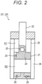
- both the front wheel side damper DF and the rear wheel side damper DR are configured to include: a cylinder 20; a piston 21 that is slidably inserted into the cylinder 20 and partitions the cylinder 20 into an extension side chamber R1 and a compression side chamber R2; a piston rod 22 that is movably inserted to the cylinder 20, and is connected to the piston 21; a damping valve 23 that is provided in the piston 21, and makes the extension side chamber R1 and the compression side chamber R2 communicate with each other; a bypass passage 24 that makes the extension side chamber R1 and the compression side chamber R2 communicate with each other by bypassing the damping valve 23; a damping force adjustment valve 25 provided in the middle of the bypass passage 24; a reservoir 26 that supplies and discharges hydraulic fluid that is excessive or insufficient in the cylinder 20 by the piston rod 22 that enters and exits the cylinder 20; a suction passage 28 that allows only a flow of the hydraulic fluid from the reservoir 26 to the compression side chamber
- the damping force adjustment valve 25 is an electromagnetic valve in this example, and can change the resistance applied to the flow of the passing hydraulic fluid by adjusting an opening degree.
- the damping force adjustment valve 25 applies resistance to both flow of the hydraulic fluid from the extension side chamber R1 to the compression side chamber R2 and flow of the hydraulic fluid from the compression side chamber R2 to the extension side chamber R1.
- the damping force adjustment valve 25 may be an electromagnetic relief valve capable of adjusting an valve opening pressure, or may be a rotary valve driven by a rotary actuator such as a stepping motor, and may be used as long as the damping force adjustment valve 25 at least can adjust the damping force in the compression side exerted by the dampers DF, DR.
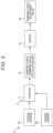
- control device C is configured to include: stroke sensors SF, SR that detect a stroke of the dampers DF, DR; and a control unit 2 that counts the extension time of the dampers DF, DR from the stroke detected by the stroke sensors SF, SR, adjusts the resistance applied to hydraulic fluid by the damping force adjustment valve 25, and controls the damping force exerted by the dampers DF, DR.
- the stroke sensors SF, SR detect the stroke of the corresponding dampers DF, DR, respectively.
- the stroke sensors SF, SR may be built in the dampers DF, DR, or may be interposed between the body B, and the front wheel WF and the rear wheel WR.
- the control unit 2 processes the signals output from the stroke sensors SF, SR described above, counts the extension time of the dampers DF, DR, obtains a damping force command value including a command given to the damping force adjustment valve 25 according to the extension time, and supplies a current to the damping force adjustment valve 25 as instructed by the damping force command value.
- the control unit 2 includes: a counter 11 that counts the extension time of the dampers DF, DR; a damping force command value calculation unit 12 that obtains a damping force command value from the extension time; and a driver 13 that supplies a current to the damping force adjustment valve 25 as instructed by the damping force command value.
- the counter 11 detects switching of the dampers DF, DR from the contraction stroke to the extension stroke from the signals output by the stroke sensors SF, SR, and counts the time with this switching time as a starting point. This counting is continued until an extension and contraction direction is switched to contraction. More specifically, the stroke sensors SF, SR detect the stroke lengths of the dampers DF, DR at a predetermined sampling period. Therefore, the counter 11 determines whether the dampers DF, DR are in the extension stroke or the contraction stroke from the difference between the stroke lengths of the dampers DF, DR obtained in the previous sampling period and the stroke lengths of the dampers DF, DR obtained in the current sampling period.
- the counter 11 counts the time during which the dampers DF, DR are in the extension stroke with a time point in which switching is recognized, as a starting point.
- the counter 11 stops the counting and resets the extension time to zero. It should be noted that the counter 11 continues counting even when the dampers DF, DR are in a stop state in which the dampers DF, DR do not extend or contract after being switched to the extension stroke. That is, the extension time is the time from when the dampers DF, DR are switched from the contraction stroke to the extension stroke until the dampers DF, DR are switched to the contraction stroke.
- the damping force command value calculation unit 12 obtains the damping force command value for increasing the damping force of the dampers DF, DR according to the obtained extension time.
- the damping force command value calculation unit 12 since the damping force adjustment valve 25 adjusts the opening degree, in order to increase the damping force of the dampers DF, DR in proportion to the extension time, the damping force command value calculation unit 12 obtains the damping force command value so that damping coefficients of the dampers DF, DR increase. More specifically, the damping force command value calculation unit 12 obtains the damping force command value so that the opening degree of the damping force adjustment valve 25 becomes smaller as the extension time becomes longer.
- control unit 2 counts the extension time for each of the dampers DF, DR, and adjusts the opening degree of the damping force adjustment valve 25 separately for the dampers DF, DR. Therefore, the damping force command value calculation unit 12 obtains the damping force command value for each of the dampers DF, DR.
- the damping force command value calculation unit 12 obtains the damping force command value so that the damping coefficients of the dampers DF, DR increase in proportion to the obtained extension time.
- the damping force command value may be obtained so that the damping coefficients of the dampers DF, DR are increased stepwise according to the extension time or in proportion to a value of n-th power (n is a value larger than 1) of the extension time.
- the damping force command value may be obtained by preparing a map for obtaining the damping force command value with the extension time of the dampers DF, DR as a parameter, and performing map calculation from the extension time by the damping force command value calculation unit 12.
- the damping force command value calculation unit 12 may increase the damping force by obtaining the damping force command value so that the valve opening pressure of the damping force adjustment valve 25 is larger as the obtained extension time is longer. Since there is a limit in increasing of the damping force, the damping force command value may be limited to the damping force command value that maximizes the damping force or the damping coefficients of the dampers DF, DR.
- the damping force command value calculation unit 12 maintains the damping force command value for a predetermined time after the extension time of the counter 11 is reset. In this way, the damping force generated by the dampers DF, DR is maintained to be high for a while even when the dampers DF, DR are switched from the extension stroke to the contraction stroke. It is expected that, as the extension time is longer, required time for shrinkage is longer. Thus, the predetermined time may be changed so as to become longer as the extension time is longer depending on the extension time.
- the driver 13 has a drive circuit for supplying a current to the damping force adjustment valve 25 and supplies a current to the damping force adjustment valve 25 according to an instruction of the damping force command value obtained as described above.
- the driver 13 may detect the current flowing through the damping force adjustment valve 25 and control the current flowing through the damping force adjustment valve 25 by current feedback control. In this way, the driver 13 supplies the current to the damping force adjustment valve 25, the opening degree of the damping force adjustment valve 25 is adjusted according to the instruction of the damping force command value, and the damping force of the dampers DF, DR is controlled.
- control unit 2 counts the extension time for each of the dampers DF, DR, and increases the damping force generated by the dampers DF, DR as the extension time of the dampers DF, DR is longer.
- a hardware resource in each part of the control unit 2 described above may be configured as a known system including: an amplifier for amplifying the signals output by the stroke sensors SF, SR; a converter that converts an analog signal into a digital signal; a computer system composed of a storage device such as a central processing unit (CPU) or a read only memory (ROM), a random access memory (RAM), a crystal oscillator, and a bus line connecting these components; and a drive circuit that drives the damping force adjustment valve 25 forming part of the driver 13.
- a control processing procedure for processing each signal to obtain the damping force command value and controlling the driver 13 may be stored in advance in the ROM or another storage device, as a program.
- the control unit 2 is a known computer system as hardware.
- the control unit 2 may be integrated into the ECU without being separately provided.
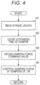
- the control unit 2 reads the stroke lengths detected by the stroke sensors SF, SR (step 101). Subsequently, the control unit 2 counts the extension time of the dampers DF, DR (step 102). When the dampers DF, DR are in the contraction stroke, the counter 11 resets the extension time. The control unit 2 obtains the damping force command value from the counted extension time (step 103). The control unit 2 supplies a current from the driver 13 to the damping force adjustment valve 25 to control the damping force of each of the dampers DF, DR (step 104). The control unit 2 repeatedly processes from steps 101 to 104 described above, and controls the damping force of the dampers DF, DR.
- control unit 2 executes the series of processes described above, thereby realizing the processes of each part of the counter 11, the damping force command value calculation unit 12, and the driver 13.
- Each part described above is realized by reading the program described above and executing each calculation processing described above by the CPU.
- the damper control device C and the suspension device S are configured as described above and control the damping force of the dampers DF, DR based on the extension time of the dampers DF, DR.
- the dampers DF, DR are not subjected to the compressive force from the wheels WF, WR, and therefore extend. That is, when the vehicle V jumps, the dampers DF, DR are always switched to the extension stroke.
- the longer air time of the vehicle V is, the longer the extension time described above becomes. Therefore, when the extension time is long, the maximum separation distance between the ground and the vehicle V increases for the extent of the extension time, and the jump becomes large.
- the jump includes not only a case where the vehicle V jumps upward against the force of gravity but also a case where the vehicle V falls to the ground that is deep from a high place. Even when the vehicle V falls from a high place, if the air time is long, the magnitude of the jump increases as similar to a case of jumping upward.
- the damper control device C and the suspension device S of the present invention control the damping force of the dampers DF, DR based on the extension time, the damping force exerted by the dampers DF, DR can be optimally controlled according to the magnitude of the jump of the vehicle V. Therefore, in the damper control device C and the suspension device S of the present invention, the damping force of the dampers DF, DR does not become excessively large when the jump of the vehicle V is small or the damping force of the dampers DF, DR does not become excessively small when the jump of the vehicle V is large. Therefore, in the damper control device C and the suspension device S of the present invention, a large shock is not applied to the rider of the vehicle V. As described above, according to the damper control device C and the suspension device S of the present invention, the dampers DF, DR can exert the optimum damping force according to the magnitude of the jump of the vehicle V.
- the damping force of the dampers DF, DR When the extension side damping force of the dampers DF, DR is also increased according to the length of the extension time, the damping force of the dampers DF, DR after the landing of when the contraction stroke is made transition to the extension stroke also can be large. Thus, sudden extension of the suspension spring can also be suppressed and rebound of the vehicle V can be suppressed.
- stroke sensors SF, SR for detecting the stroke lengths of the dampers DF, DR are provided, and the extension time is obtained from the stroke lengths. Since the extension time is obtained from the stroke length in the damper control device C in this way, counting of the extension time becomes highly easy and correct extension time can be obtained. Since the stroke sensors SF, SR for detecting the stroke lengths of the dampers DF, DR are provided, in the case where there is a plurality of dampers in the damper control device C, the extension time of the dampers DF, DR are obtained, and the damping force of the dampers DF, DR can be optimally controlled.
- the present invention can be applied only to the front side damper DF or the rear side damper DR. Since the stroke sensors SF, SR detect the stroke lengths of the dampers DF, DR, the stroke sensors SF, SR can be incorporated in the dampers DF, DR, so that it is not necessary to provide a special structure for attaching the stroke sensors SF, SR in the vehicle V.
- the damping force command value calculation unit 12 obtains the damping force command value so that the damping coefficients of the dampers DF, DR are set to predetermined values regardless of the extension time.
- the damping force adjustment valve 25 can directly control the damping force of the dampers DF, DR
- the damping force command value calculation unit 12 obtains the damping force command value so that the damping force command value is a predetermined value regardless of the extension time.
- control in the damper control device C may be used in combination with other control.
- control may be performed by using this control together with posture control of the vehicle body B by skyhook control or the like, comparing the damping force command value by the posture control with the damping force command value by the control of the present invention, and adopting the damping force command value that increases the generation damping force of the dampers DF, DR.
- control device C and the suspension device S can be used for controlling a damper of an automobile or the like.
- control device C and the suspension device S are effective when being adopted to a saddle-ride vehicle with which the vehicle V is utilized for a motocross or off-road, and the jump frequently occurs.
- an electrode or coil for applying an electric or magnetic field may be provided so that the damping force adjustment can be performed.
- the bypass passage 24 may also be eliminated, and instead of the damping valve 23, an electrode or a coil may be provided in a passage communicating the extension side chamber R1 and the compression side chamber R2.
Landscapes
- Engineering & Computer Science (AREA)
- General Engineering & Computer Science (AREA)
- Mechanical Engineering (AREA)
- Axle Suspensions And Sidecars For Cycles (AREA)
- Vehicle Body Suspensions (AREA)
- Fluid-Damping Devices (AREA)
Claims (4)
- Dämpfersteuerungsvorrichtung (C) zum Steuern einer Dämpfungskraft eines Dämpfers (DF, DR) basierend auf einer Ausfahrzeit des Dämpfers (DF, DR), die die Dämpfungskraft einstellen kann und zwischen einer Karosserie (B) und einem Rad (WF, WR) in einem Fahrzeug (V) angeordnet ist, umfassend:Hubsensoren (SF, SR), die einen Hub des Dämpfers (DF, DR) erfassen; undeinen Zähler (11), der ein Umschalten des Dämpfers (DF, DR) vom Einfahrhub zum Ausfahrhub ausgehend von den von den Hubsensoren (SF, SR) ausgegebenen Signalen detektiert und die Ausfahrzeit mit dieser Umschaltzeit als Startpunkt zählt,wobei der Zähler (11) die Zählung stoppt und die Ausfahrzeit auf Null zurücksetzt wenn der Dämpfer (DF, DR) vom Ausfahrhub in den Einfahrhub umgeschaltet wird, und die Zählung fortsetzt selbst wenn sich der Dämpfer (DF, DR) in einem Stoppzustand befindet, in dem der Dämpfer (DF, DR) nach dem Umschalten in den Ausfahrhub weder ausfährt noch einfährt,und die Dämpfersteuerungsvorrichtung (C) die Dämpfungskraft in einer Druckseite des Dämpfers (DF, DR) so einstellt, dass sie umso größer ist, je länger die Ausfahrzeit des Dämpfers (DF, DR) ist.
- Dämpfersteuerungsvorrichtung (C) nach Anspruch 1, wobei
die Dämpfersteuerungsvorrichtung (C) die Dämpfungskraft in einer Ausfahrseite des Dämpfers (DF, DR) so einstellt, dass sie umso größer ist, je länger die Ausfahrzeit des Dämpfers (DF, DR) ist. - Dämpfersteuerungsvorrichtung (C) nach Anspruch 1, wobeidie Dämpfersteuerungsvorrichtung (C) einen Hubsensor (SF, SR) enthält, der eine Hublänge des Dämpfers (DF, DR) erfasst unddie Ausfahrzeit aus der Hublänge ermittelt.
- Aufhängevorrichtung (C), umfassend:einen Dämpfer (DF, DR), der eine Dämpfungskraft einstellen kann und so konfiguriert ist, dass er zwischen einer Karosserie (B) und einem Rad (WF, WR) eines Zweiradfahrzeugs (V) angeordnet ist, unddie Dämpfersteuerungsvorrichtung (C) nach einem der Ansprüche 1 bis 3.
Applications Claiming Priority (2)
| Application Number | Priority Date | Filing Date | Title |
|---|---|---|---|
| JP2016053224A JP6744733B2 (ja) | 2016-03-17 | 2016-03-17 | 緩衝器の制御装置およびサスペンション装置 |
| PCT/JP2017/008159 WO2017159370A1 (ja) | 2016-03-17 | 2017-03-01 | 緩衝器の制御装置およびサスペンション装置 |
Publications (3)
| Publication Number | Publication Date |
|---|---|
| EP3431375A1 EP3431375A1 (de) | 2019-01-23 |
| EP3431375A4 EP3431375A4 (de) | 2019-10-23 |
| EP3431375B1 true EP3431375B1 (de) | 2023-08-09 |
Family
ID=59852208
Family Applications (1)
| Application Number | Title | Priority Date | Filing Date |
|---|---|---|---|
| EP17766373.9A Active EP3431375B1 (de) | 2016-03-17 | 2017-03-01 | Dämpferregelvorrichtung und aufhängevorrichtung |
Country Status (4)
| Country | Link |
|---|---|
| US (1) | US20190072149A1 (de) |
| EP (1) | EP3431375B1 (de) |
| JP (1) | JP6744733B2 (de) |
| WO (1) | WO2017159370A1 (de) |
Families Citing this family (4)
| Publication number | Priority date | Publication date | Assignee | Title |
|---|---|---|---|---|
| JP6581511B2 (ja) * | 2016-01-05 | 2019-09-25 | Kyb株式会社 | フロントフォーク |
| JP6444472B1 (ja) * | 2017-10-19 | 2018-12-26 | 株式会社ショーワ | 懸架装置及び記録媒体 |
| JP2021187296A (ja) | 2020-05-29 | 2021-12-13 | ロベルト・ボッシュ・ゲゼルシャフト・ミト・ベシュレンクテル・ハフツングRobert Bosch Gmbh | 制御装置、車両及び制御方法 |
| DE102022108403A1 (de) * | 2022-04-07 | 2023-10-12 | Bayerische Motoren Werke Aktiengesellschaft | Verfahren und Vorrichtung zur Ermittlung des Beladungszustands eines Motorrads |
Citations (4)
| Publication number | Priority date | Publication date | Assignee | Title |
|---|---|---|---|---|
| JPS6137511A (ja) * | 1984-07-31 | 1986-02-22 | Nissan Motor Co Ltd | 車両用シヨツクアブソ−バ制御装置 |
| US5133574A (en) * | 1988-11-18 | 1992-07-28 | Atsugi Unisia Corporation | Variable damping characteristics suspension system for automotive suspension system with variable damping characteristics shock absorber with input vibration frequency dependent variation characteristics |
| US20120247888A1 (en) * | 2011-03-30 | 2012-10-04 | Hiroshi Chikuma | Suspension apparatus |
| WO2015041298A1 (ja) * | 2013-09-19 | 2015-03-26 | カヤバ工業株式会社 | 緩衝装置 |
Family Cites Families (14)
| Publication number | Priority date | Publication date | Assignee | Title |
|---|---|---|---|---|
| US4726604A (en) * | 1985-01-28 | 1988-02-23 | Toyota Jidosha Kabushiki Kaisha | Rear suspension controller |
| JP2589067B2 (ja) * | 1985-10-01 | 1997-03-12 | トヨタ自動車株式会社 | サスペンシヨン制御装置 |
| JPS6395991U (de) * | 1986-12-12 | 1988-06-21 | ||
| JP2788463B2 (ja) * | 1989-01-09 | 1998-08-20 | ヤマハ発動機株式会社 | 減衰器の減衰力制御装置 |
| JP2954976B2 (ja) * | 1990-04-27 | 1999-09-27 | ヤマハ発動機株式会社 | 減衰器の減衰力制御装置 |
| JP3088552B2 (ja) * | 1991-10-15 | 2000-09-18 | カヤバ工業株式会社 | 車高調整装置 |
| US6360148B1 (en) * | 1999-11-16 | 2002-03-19 | Michael W. Halpin | Method and apparatus for controlling hydraulic dampers |
| NL1019313C2 (nl) * | 2001-11-06 | 2003-05-12 | Koni Bv | Schokdemper met frequentie afhankelijke demping. |
| US7942248B2 (en) * | 2002-12-31 | 2011-05-17 | Lord Corporation | Adjustable damping control with end stop |
| US7931286B2 (en) * | 2003-05-02 | 2011-04-26 | Melcher Thomas W | Vehicle lean and alignment control system |
| GB2406548A (en) * | 2003-10-03 | 2005-04-06 | Trelleborg Ab | Air suspension system |
| JP2005199944A (ja) | 2004-01-19 | 2005-07-28 | Yamaha Motor Co Ltd | 自動二輪車用減衰器の減衰力制御装置 |
| DE102013021892A1 (de) * | 2013-12-23 | 2015-06-25 | Dt Swiss Ag | Fahrwerksteuerung für ein Zweirad und Verfahren |
| JP6482909B2 (ja) * | 2015-03-12 | 2019-03-13 | 株式会社ショーワ | 車両懸架システム |
-
2016
- 2016-03-17 JP JP2016053224A patent/JP6744733B2/ja active Active
-
2017
- 2017-03-01 EP EP17766373.9A patent/EP3431375B1/de active Active
- 2017-03-01 WO PCT/JP2017/008159 patent/WO2017159370A1/ja not_active Ceased
- 2017-03-01 US US16/084,639 patent/US20190072149A1/en not_active Abandoned
Patent Citations (4)
| Publication number | Priority date | Publication date | Assignee | Title |
|---|---|---|---|---|
| JPS6137511A (ja) * | 1984-07-31 | 1986-02-22 | Nissan Motor Co Ltd | 車両用シヨツクアブソ−バ制御装置 |
| US5133574A (en) * | 1988-11-18 | 1992-07-28 | Atsugi Unisia Corporation | Variable damping characteristics suspension system for automotive suspension system with variable damping characteristics shock absorber with input vibration frequency dependent variation characteristics |
| US20120247888A1 (en) * | 2011-03-30 | 2012-10-04 | Hiroshi Chikuma | Suspension apparatus |
| WO2015041298A1 (ja) * | 2013-09-19 | 2015-03-26 | カヤバ工業株式会社 | 緩衝装置 |
Also Published As
| Publication number | Publication date |
|---|---|
| WO2017159370A1 (ja) | 2017-09-21 |
| US20190072149A1 (en) | 2019-03-07 |
| JP2017165298A (ja) | 2017-09-21 |
| EP3431375A4 (de) | 2019-10-23 |
| JP6744733B2 (ja) | 2020-08-19 |
| EP3431375A1 (de) | 2019-01-23 |
Similar Documents
| Publication | Publication Date | Title |
|---|---|---|
| US11549565B2 (en) | Method and apparatus for an adjustable damper | |
| US12145415B2 (en) | Suspension with hydraulic preload adjust | |
| EP3431375B1 (de) | Dämpferregelvorrichtung und aufhängevorrichtung | |
| US9278599B2 (en) | Suspension control apparatus | |
| US20190203798A1 (en) | Position sensitive suspension damping with an active valve | |
| JP5934470B2 (ja) | サスペンション装置 | |
| KR101728254B1 (ko) | 댐퍼 제어 장치 | |
| EP2939857A2 (de) | Verfahren und vorrichtung für einen verstellbaren dämpfer | |
| JP5503328B2 (ja) | 減衰力可変ダンパの制御装置 | |
| US20070029711A1 (en) | Suspension apparatus for vehicle | |
| US10618367B2 (en) | Damper control device and suspension apparatus | |
| EP3163115B1 (de) | Dämpfersteuerungsvorrichtung | |
| EP3431376B1 (de) | Dämpfersteuerungsvorrichtung und aufhängungsvorrichtung | |
| CN110573416A (zh) | 悬挂装置及悬挂控制装置 | |
| EP3663605A1 (de) | Positionsempfindliche aufhängungsdämpfung mit einem aktiven ventil | |
| EP1628039B1 (de) | Hydraulischer Stossdämpfer | |
| JP2015083469A (ja) | サスペンション装置 | |
| JP2010155474A (ja) | サスペンション制御装置、及びサスペンション制御方法 |
Legal Events
| Date | Code | Title | Description |
|---|---|---|---|
| STAA | Information on the status of an ep patent application or granted ep patent |
Free format text: STATUS: THE INTERNATIONAL PUBLICATION HAS BEEN MADE |
|
| PUAI | Public reference made under article 153(3) epc to a published international application that has entered the european phase |
Free format text: ORIGINAL CODE: 0009012 |
|
| STAA | Information on the status of an ep patent application or granted ep patent |
Free format text: STATUS: REQUEST FOR EXAMINATION WAS MADE |
|
| 17P | Request for examination filed |
Effective date: 20181008 |
|
| AK | Designated contracting states |
Kind code of ref document: A1 Designated state(s): AL AT BE BG CH CY CZ DE DK EE ES FI FR GB GR HR HU IE IS IT LI LT LU LV MC MK MT NL NO PL PT RO RS SE SI SK SM TR |
|
| AX | Request for extension of the european patent |
Extension state: BA ME |
|
| DAV | Request for validation of the european patent (deleted) | ||
| DAX | Request for extension of the european patent (deleted) | ||
| A4 | Supplementary search report drawn up and despatched |
Effective date: 20190923 |
|
| RIC1 | Information provided on ipc code assigned before grant |
Ipc: F16F 9/46 20060101AFI20190917BHEP Ipc: B60G 17/0165 20060101ALI20190917BHEP Ipc: F16F 9/32 20060101ALI20190917BHEP Ipc: B62K 25/06 20060101ALI20190917BHEP Ipc: F16F 9/19 20060101ALN20190917BHEP |
|
| STAA | Information on the status of an ep patent application or granted ep patent |
Free format text: STATUS: EXAMINATION IS IN PROGRESS |
|
| 17Q | First examination report despatched |
Effective date: 20201014 |
|
| REG | Reference to a national code |
Ref country code: DE Free format text: PREVIOUS MAIN CLASS: B62K0025040000 Ipc: F16F0009460000 Ref country code: DE Ref legal event code: R079 Ref document number: 602017072477 Country of ref document: DE Free format text: PREVIOUS MAIN CLASS: B62K0025040000 Ipc: F16F0009460000 |
|
| RIC1 | Information provided on ipc code assigned before grant |
Ipc: B62K 25/04 20060101ALN20230116BHEP Ipc: F16F 9/19 20060101ALN20230116BHEP Ipc: B62K 25/08 20060101ALI20230116BHEP Ipc: B60G 17/0165 20060101ALI20230116BHEP Ipc: F16F 9/32 20060101ALI20230116BHEP Ipc: F16F 9/46 20060101AFI20230116BHEP |
|
| GRAP | Despatch of communication of intention to grant a patent |
Free format text: ORIGINAL CODE: EPIDOSNIGR1 |
|
| STAA | Information on the status of an ep patent application or granted ep patent |
Free format text: STATUS: GRANT OF PATENT IS INTENDED |
|
| INTG | Intention to grant announced |
Effective date: 20230228 |
|
| GRAS | Grant fee paid |
Free format text: ORIGINAL CODE: EPIDOSNIGR3 |
|
| GRAA | (expected) grant |
Free format text: ORIGINAL CODE: 0009210 |
|
| STAA | Information on the status of an ep patent application or granted ep patent |
Free format text: STATUS: THE PATENT HAS BEEN GRANTED |
|
| AK | Designated contracting states |
Kind code of ref document: B1 Designated state(s): AL AT BE BG CH CY CZ DE DK EE ES FI FR GB GR HR HU IE IS IT LI LT LU LV MC MK MT NL NO PL PT RO RS SE SI SK SM TR |
|
| REG | Reference to a national code |
Ref country code: GB Ref legal event code: FG4D |
|
| REG | Reference to a national code |
Ref country code: CH Ref legal event code: EP |
|
| REG | Reference to a national code |
Ref country code: DE Ref legal event code: R096 Ref document number: 602017072477 Country of ref document: DE |
|
| REG | Reference to a national code |
Ref country code: IE Ref legal event code: FG4D |
|
| REG | Reference to a national code |
Ref country code: SE Ref legal event code: TRGR |
|
| REG | Reference to a national code |
Ref country code: LT Ref legal event code: MG9D |
|
| REG | Reference to a national code |
Ref country code: NL Ref legal event code: MP Effective date: 20230809 |
|
| PG25 | Lapsed in a contracting state [announced via postgrant information from national office to epo] |
Ref country code: GR Free format text: LAPSE BECAUSE OF FAILURE TO SUBMIT A TRANSLATION OF THE DESCRIPTION OR TO PAY THE FEE WITHIN THE PRESCRIBED TIME-LIMIT Effective date: 20231110 |
|
| PG25 | Lapsed in a contracting state [announced via postgrant information from national office to epo] |
Ref country code: IS Free format text: LAPSE BECAUSE OF FAILURE TO SUBMIT A TRANSLATION OF THE DESCRIPTION OR TO PAY THE FEE WITHIN THE PRESCRIBED TIME-LIMIT Effective date: 20231209 |
|
| PG25 | Lapsed in a contracting state [announced via postgrant information from national office to epo] |
Ref country code: RS Free format text: LAPSE BECAUSE OF FAILURE TO SUBMIT A TRANSLATION OF THE DESCRIPTION OR TO PAY THE FEE WITHIN THE PRESCRIBED TIME-LIMIT Effective date: 20230809 Ref country code: PT Free format text: LAPSE BECAUSE OF FAILURE TO SUBMIT A TRANSLATION OF THE DESCRIPTION OR TO PAY THE FEE WITHIN THE PRESCRIBED TIME-LIMIT Effective date: 20231211 Ref country code: NO Free format text: LAPSE BECAUSE OF FAILURE TO SUBMIT A TRANSLATION OF THE DESCRIPTION OR TO PAY THE FEE WITHIN THE PRESCRIBED TIME-LIMIT Effective date: 20231109 Ref country code: NL Free format text: LAPSE BECAUSE OF FAILURE TO SUBMIT A TRANSLATION OF THE DESCRIPTION OR TO PAY THE FEE WITHIN THE PRESCRIBED TIME-LIMIT Effective date: 20230809 Ref country code: LV Free format text: LAPSE BECAUSE OF FAILURE TO SUBMIT A TRANSLATION OF THE DESCRIPTION OR TO PAY THE FEE WITHIN THE PRESCRIBED TIME-LIMIT Effective date: 20230809 Ref country code: LT Free format text: LAPSE BECAUSE OF FAILURE TO SUBMIT A TRANSLATION OF THE DESCRIPTION OR TO PAY THE FEE WITHIN THE PRESCRIBED TIME-LIMIT Effective date: 20230809 Ref country code: IS Free format text: LAPSE BECAUSE OF FAILURE TO SUBMIT A TRANSLATION OF THE DESCRIPTION OR TO PAY THE FEE WITHIN THE PRESCRIBED TIME-LIMIT Effective date: 20231209 Ref country code: HR Free format text: LAPSE BECAUSE OF FAILURE TO SUBMIT A TRANSLATION OF THE DESCRIPTION OR TO PAY THE FEE WITHIN THE PRESCRIBED TIME-LIMIT Effective date: 20230809 Ref country code: GR Free format text: LAPSE BECAUSE OF FAILURE TO SUBMIT A TRANSLATION OF THE DESCRIPTION OR TO PAY THE FEE WITHIN THE PRESCRIBED TIME-LIMIT Effective date: 20231110 Ref country code: FI Free format text: LAPSE BECAUSE OF FAILURE TO SUBMIT A TRANSLATION OF THE DESCRIPTION OR TO PAY THE FEE WITHIN THE PRESCRIBED TIME-LIMIT Effective date: 20230809 |
|
| PG25 | Lapsed in a contracting state [announced via postgrant information from national office to epo] |
Ref country code: PL Free format text: LAPSE BECAUSE OF FAILURE TO SUBMIT A TRANSLATION OF THE DESCRIPTION OR TO PAY THE FEE WITHIN THE PRESCRIBED TIME-LIMIT Effective date: 20230809 |
|
| PG25 | Lapsed in a contracting state [announced via postgrant information from national office to epo] |
Ref country code: ES Free format text: LAPSE BECAUSE OF FAILURE TO SUBMIT A TRANSLATION OF THE DESCRIPTION OR TO PAY THE FEE WITHIN THE PRESCRIBED TIME-LIMIT Effective date: 20230809 |
|
| PG25 | Lapsed in a contracting state [announced via postgrant information from national office to epo] |
Ref country code: SM Free format text: LAPSE BECAUSE OF FAILURE TO SUBMIT A TRANSLATION OF THE DESCRIPTION OR TO PAY THE FEE WITHIN THE PRESCRIBED TIME-LIMIT Effective date: 20230809 Ref country code: RO Free format text: LAPSE BECAUSE OF FAILURE TO SUBMIT A TRANSLATION OF THE DESCRIPTION OR TO PAY THE FEE WITHIN THE PRESCRIBED TIME-LIMIT Effective date: 20230809 Ref country code: ES Free format text: LAPSE BECAUSE OF FAILURE TO SUBMIT A TRANSLATION OF THE DESCRIPTION OR TO PAY THE FEE WITHIN THE PRESCRIBED TIME-LIMIT Effective date: 20230809 Ref country code: EE Free format text: LAPSE BECAUSE OF FAILURE TO SUBMIT A TRANSLATION OF THE DESCRIPTION OR TO PAY THE FEE WITHIN THE PRESCRIBED TIME-LIMIT Effective date: 20230809 Ref country code: DK Free format text: LAPSE BECAUSE OF FAILURE TO SUBMIT A TRANSLATION OF THE DESCRIPTION OR TO PAY THE FEE WITHIN THE PRESCRIBED TIME-LIMIT Effective date: 20230809 Ref country code: CZ Free format text: LAPSE BECAUSE OF FAILURE TO SUBMIT A TRANSLATION OF THE DESCRIPTION OR TO PAY THE FEE WITHIN THE PRESCRIBED TIME-LIMIT Effective date: 20230809 Ref country code: SK Free format text: LAPSE BECAUSE OF FAILURE TO SUBMIT A TRANSLATION OF THE DESCRIPTION OR TO PAY THE FEE WITHIN THE PRESCRIBED TIME-LIMIT Effective date: 20230809 |
|
| REG | Reference to a national code |
Ref country code: DE Ref legal event code: R097 Ref document number: 602017072477 Country of ref document: DE |
|
| PLBE | No opposition filed within time limit |
Free format text: ORIGINAL CODE: 0009261 |
|
| STAA | Information on the status of an ep patent application or granted ep patent |
Free format text: STATUS: NO OPPOSITION FILED WITHIN TIME LIMIT |
|
| 26N | No opposition filed |
Effective date: 20240513 |
|
| PG25 | Lapsed in a contracting state [announced via postgrant information from national office to epo] |
Ref country code: SI Free format text: LAPSE BECAUSE OF FAILURE TO SUBMIT A TRANSLATION OF THE DESCRIPTION OR TO PAY THE FEE WITHIN THE PRESCRIBED TIME-LIMIT Effective date: 20230809 |
|
| REG | Reference to a national code |
Ref country code: CH Ref legal event code: PL |
|
| PG25 | Lapsed in a contracting state [announced via postgrant information from national office to epo] |
Ref country code: BG Free format text: LAPSE BECAUSE OF FAILURE TO SUBMIT A TRANSLATION OF THE DESCRIPTION OR TO PAY THE FEE WITHIN THE PRESCRIBED TIME-LIMIT Effective date: 20230809 |
|
| PG25 | Lapsed in a contracting state [announced via postgrant information from national office to epo] |
Ref country code: LU Free format text: LAPSE BECAUSE OF NON-PAYMENT OF DUE FEES Effective date: 20240301 |
|
| PG25 | Lapsed in a contracting state [announced via postgrant information from national office to epo] |
Ref country code: MC Free format text: LAPSE BECAUSE OF FAILURE TO SUBMIT A TRANSLATION OF THE DESCRIPTION OR TO PAY THE FEE WITHIN THE PRESCRIBED TIME-LIMIT Effective date: 20230809 |
|
| GBPC | Gb: european patent ceased through non-payment of renewal fee |
Effective date: 20240301 |
|
| PG25 | Lapsed in a contracting state [announced via postgrant information from national office to epo] |
Ref country code: MC Free format text: LAPSE BECAUSE OF FAILURE TO SUBMIT A TRANSLATION OF THE DESCRIPTION OR TO PAY THE FEE WITHIN THE PRESCRIBED TIME-LIMIT Effective date: 20230809 Ref country code: LU Free format text: LAPSE BECAUSE OF NON-PAYMENT OF DUE FEES Effective date: 20240301 Ref country code: BG Free format text: LAPSE BECAUSE OF FAILURE TO SUBMIT A TRANSLATION OF THE DESCRIPTION OR TO PAY THE FEE WITHIN THE PRESCRIBED TIME-LIMIT Effective date: 20230809 |
|
| REG | Reference to a national code |
Ref country code: BE Ref legal event code: MM Effective date: 20240331 |
|
| PG25 | Lapsed in a contracting state [announced via postgrant information from national office to epo] |
Ref country code: BE Free format text: LAPSE BECAUSE OF NON-PAYMENT OF DUE FEES Effective date: 20240331 |
|
| PG25 | Lapsed in a contracting state [announced via postgrant information from national office to epo] |
Ref country code: GB Free format text: LAPSE BECAUSE OF NON-PAYMENT OF DUE FEES Effective date: 20240301 |
|
| PG25 | Lapsed in a contracting state [announced via postgrant information from national office to epo] |
Ref country code: FR Free format text: LAPSE BECAUSE OF NON-PAYMENT OF DUE FEES Effective date: 20240331 |
|
| PG25 | Lapsed in a contracting state [announced via postgrant information from national office to epo] |
Ref country code: IE Free format text: LAPSE BECAUSE OF NON-PAYMENT OF DUE FEES Effective date: 20240301 |
|
| PG25 | Lapsed in a contracting state [announced via postgrant information from national office to epo] |
Ref country code: IE Free format text: LAPSE BECAUSE OF NON-PAYMENT OF DUE FEES Effective date: 20240301 Ref country code: GB Free format text: LAPSE BECAUSE OF NON-PAYMENT OF DUE FEES Effective date: 20240301 Ref country code: FR Free format text: LAPSE BECAUSE OF NON-PAYMENT OF DUE FEES Effective date: 20240331 Ref country code: BE Free format text: LAPSE BECAUSE OF NON-PAYMENT OF DUE FEES Effective date: 20240331 Ref country code: CH Free format text: LAPSE BECAUSE OF NON-PAYMENT OF DUE FEES Effective date: 20240331 |
|
| PGFP | Annual fee paid to national office [announced via postgrant information from national office to epo] |
Ref country code: SE Payment date: 20250321 Year of fee payment: 9 |
|
| PGFP | Annual fee paid to national office [announced via postgrant information from national office to epo] |
Ref country code: DE Payment date: 20250319 Year of fee payment: 9 |
|
| PGFP | Annual fee paid to national office [announced via postgrant information from national office to epo] |
Ref country code: AT Payment date: 20250320 Year of fee payment: 9 |
|
| PGFP | Annual fee paid to national office [announced via postgrant information from national office to epo] |
Ref country code: IT Payment date: 20250325 Year of fee payment: 9 |
|
| PG25 | Lapsed in a contracting state [announced via postgrant information from national office to epo] |
Ref country code: CY Free format text: LAPSE BECAUSE OF FAILURE TO SUBMIT A TRANSLATION OF THE DESCRIPTION OR TO PAY THE FEE WITHIN THE PRESCRIBED TIME-LIMIT; INVALID AB INITIO Effective date: 20170301 |
|
| PG25 | Lapsed in a contracting state [announced via postgrant information from national office to epo] |
Ref country code: HU Free format text: LAPSE BECAUSE OF FAILURE TO SUBMIT A TRANSLATION OF THE DESCRIPTION OR TO PAY THE FEE WITHIN THE PRESCRIBED TIME-LIMIT; INVALID AB INITIO Effective date: 20170301 |
|
| PG25 | Lapsed in a contracting state [announced via postgrant information from national office to epo] |
Ref country code: TR Free format text: LAPSE BECAUSE OF FAILURE TO SUBMIT A TRANSLATION OF THE DESCRIPTION OR TO PAY THE FEE WITHIN THE PRESCRIBED TIME-LIMIT Effective date: 20230809 |
|
| REG | Reference to a national code |
Ref country code: AT Ref legal event code: UEP Ref document number: 1597849 Country of ref document: AT Kind code of ref document: T Effective date: 20230809 |