EP3431322A1 - Laterally expandable photovoltaic device and solar powered automobile - Google Patents
Laterally expandable photovoltaic device and solar powered automobile Download PDFInfo
- Publication number
- EP3431322A1 EP3431322A1 EP18750305.7A EP18750305A EP3431322A1 EP 3431322 A1 EP3431322 A1 EP 3431322A1 EP 18750305 A EP18750305 A EP 18750305A EP 3431322 A1 EP3431322 A1 EP 3431322A1
- Authority
- EP
- European Patent Office
- Prior art keywords
- movable plate
- vehicle body
- photovoltaic device
- vehicle
- solar
- Prior art date
- Legal status (The legal status is an assumption and is not a legal conclusion. Google has not performed a legal analysis and makes no representation as to the accuracy of the status listed.)
- Withdrawn
Links
Images


Classifications
-
- B—PERFORMING OPERATIONS; TRANSPORTING
- B60—VEHICLES IN GENERAL
- B60K—ARRANGEMENT OR MOUNTING OF PROPULSION UNITS OR OF TRANSMISSIONS IN VEHICLES; ARRANGEMENT OR MOUNTING OF PLURAL DIVERSE PRIME-MOVERS IN VEHICLES; AUXILIARY DRIVES FOR VEHICLES; INSTRUMENTATION OR DASHBOARDS FOR VEHICLES; ARRANGEMENTS IN CONNECTION WITH COOLING, AIR INTAKE, GAS EXHAUST OR FUEL SUPPLY OF PROPULSION UNITS IN VEHICLES
- B60K16/00—Arrangements in connection with power supply of propulsion units in vehicles from forces of nature, e.g. sun or wind
-
- B—PERFORMING OPERATIONS; TRANSPORTING
- B60—VEHICLES IN GENERAL
- B60L—PROPULSION OF ELECTRICALLY-PROPELLED VEHICLES; SUPPLYING ELECTRIC POWER FOR AUXILIARY EQUIPMENT OF ELECTRICALLY-PROPELLED VEHICLES; ELECTRODYNAMIC BRAKE SYSTEMS FOR VEHICLES IN GENERAL; MAGNETIC SUSPENSION OR LEVITATION FOR VEHICLES; MONITORING OPERATING VARIABLES OF ELECTRICALLY-PROPELLED VEHICLES; ELECTRIC SAFETY DEVICES FOR ELECTRICALLY-PROPELLED VEHICLES
- B60L8/00—Electric propulsion with power supply from forces of nature, e.g. sun or wind
-
- B—PERFORMING OPERATIONS; TRANSPORTING
- B60—VEHICLES IN GENERAL
- B60L—PROPULSION OF ELECTRICALLY-PROPELLED VEHICLES; SUPPLYING ELECTRIC POWER FOR AUXILIARY EQUIPMENT OF ELECTRICALLY-PROPELLED VEHICLES; ELECTRODYNAMIC BRAKE SYSTEMS FOR VEHICLES IN GENERAL; MAGNETIC SUSPENSION OR LEVITATION FOR VEHICLES; MONITORING OPERATING VARIABLES OF ELECTRICALLY-PROPELLED VEHICLES; ELECTRIC SAFETY DEVICES FOR ELECTRICALLY-PROPELLED VEHICLES
- B60L53/00—Methods of charging batteries, specially adapted for electric vehicles; Charging stations or on-board charging equipment therefor; Exchange of energy storage elements in electric vehicles
- B60L53/50—Charging stations characterised by energy-storage or power-generation means
- B60L53/51—Photovoltaic means
-
- B—PERFORMING OPERATIONS; TRANSPORTING
- B60—VEHICLES IN GENERAL
- B60L—PROPULSION OF ELECTRICALLY-PROPELLED VEHICLES; SUPPLYING ELECTRIC POWER FOR AUXILIARY EQUIPMENT OF ELECTRICALLY-PROPELLED VEHICLES; ELECTRODYNAMIC BRAKE SYSTEMS FOR VEHICLES IN GENERAL; MAGNETIC SUSPENSION OR LEVITATION FOR VEHICLES; MONITORING OPERATING VARIABLES OF ELECTRICALLY-PROPELLED VEHICLES; ELECTRIC SAFETY DEVICES FOR ELECTRICALLY-PROPELLED VEHICLES
- B60L8/00—Electric propulsion with power supply from forces of nature, e.g. sun or wind
- B60L8/003—Converting light into electric energy, e.g. by using photo-voltaic systems
-
- B—PERFORMING OPERATIONS; TRANSPORTING
- B60—VEHICLES IN GENERAL
- B60R—VEHICLES, VEHICLE FITTINGS, OR VEHICLE PARTS, NOT OTHERWISE PROVIDED FOR
- B60R16/00—Electric or fluid circuits specially adapted for vehicles and not otherwise provided for; Arrangement of elements of electric or fluid circuits specially adapted for vehicles and not otherwise provided for
- B60R16/02—Electric or fluid circuits specially adapted for vehicles and not otherwise provided for; Arrangement of elements of electric or fluid circuits specially adapted for vehicles and not otherwise provided for electric constitutive elements
- B60R16/03—Electric or fluid circuits specially adapted for vehicles and not otherwise provided for; Arrangement of elements of electric or fluid circuits specially adapted for vehicles and not otherwise provided for electric constitutive elements for supply of electrical power to vehicle subsystems or for
- B60R16/0307—Electric or fluid circuits specially adapted for vehicles and not otherwise provided for; Arrangement of elements of electric or fluid circuits specially adapted for vehicles and not otherwise provided for electric constitutive elements for supply of electrical power to vehicle subsystems or for using generators driven by a machine different from the vehicle motor
-
- H—ELECTRICITY
- H02—GENERATION; CONVERSION OR DISTRIBUTION OF ELECTRIC POWER
- H02S—GENERATION OF ELECTRIC POWER BY CONVERSION OF INFRARED RADIATION, VISIBLE LIGHT OR ULTRAVIOLET LIGHT, e.g. USING PHOTOVOLTAIC [PV] MODULES
- H02S10/00—PV power plants; Combinations of PV energy systems with other systems for the generation of electric power
- H02S10/40—Mobile PV generator systems
-
- H—ELECTRICITY
- H02—GENERATION; CONVERSION OR DISTRIBUTION OF ELECTRIC POWER
- H02S—GENERATION OF ELECTRIC POWER BY CONVERSION OF INFRARED RADIATION, VISIBLE LIGHT OR ULTRAVIOLET LIGHT, e.g. USING PHOTOVOLTAIC [PV] MODULES
- H02S20/00—Supporting structures for PV modules
- H02S20/30—Supporting structures being movable or adjustable, e.g. for angle adjustment
-
- H—ELECTRICITY
- H02—GENERATION; CONVERSION OR DISTRIBUTION OF ELECTRIC POWER
- H02S—GENERATION OF ELECTRIC POWER BY CONVERSION OF INFRARED RADIATION, VISIBLE LIGHT OR ULTRAVIOLET LIGHT, e.g. USING PHOTOVOLTAIC [PV] MODULES
- H02S30/00—Structural details of PV modules other than those related to light conversion
-
- B—PERFORMING OPERATIONS; TRANSPORTING
- B60—VEHICLES IN GENERAL
- B60K—ARRANGEMENT OR MOUNTING OF PROPULSION UNITS OR OF TRANSMISSIONS IN VEHICLES; ARRANGEMENT OR MOUNTING OF PLURAL DIVERSE PRIME-MOVERS IN VEHICLES; AUXILIARY DRIVES FOR VEHICLES; INSTRUMENTATION OR DASHBOARDS FOR VEHICLES; ARRANGEMENTS IN CONNECTION WITH COOLING, AIR INTAKE, GAS EXHAUST OR FUEL SUPPLY OF PROPULSION UNITS IN VEHICLES
- B60K16/00—Arrangements in connection with power supply of propulsion units in vehicles from forces of nature, e.g. sun or wind
- B60K2016/003—Arrangements in connection with power supply of propulsion units in vehicles from forces of nature, e.g. sun or wind solar power driven
-
- Y—GENERAL TAGGING OF NEW TECHNOLOGICAL DEVELOPMENTS; GENERAL TAGGING OF CROSS-SECTIONAL TECHNOLOGIES SPANNING OVER SEVERAL SECTIONS OF THE IPC; TECHNICAL SUBJECTS COVERED BY FORMER USPC CROSS-REFERENCE ART COLLECTIONS [XRACs] AND DIGESTS
- Y02—TECHNOLOGIES OR APPLICATIONS FOR MITIGATION OR ADAPTATION AGAINST CLIMATE CHANGE
- Y02B—CLIMATE CHANGE MITIGATION TECHNOLOGIES RELATED TO BUILDINGS, e.g. HOUSING, HOUSE APPLIANCES OR RELATED END-USER APPLICATIONS
- Y02B10/00—Integration of renewable energy sources in buildings
- Y02B10/10—Photovoltaic [PV]
-
- Y—GENERAL TAGGING OF NEW TECHNOLOGICAL DEVELOPMENTS; GENERAL TAGGING OF CROSS-SECTIONAL TECHNOLOGIES SPANNING OVER SEVERAL SECTIONS OF THE IPC; TECHNICAL SUBJECTS COVERED BY FORMER USPC CROSS-REFERENCE ART COLLECTIONS [XRACs] AND DIGESTS
- Y02—TECHNOLOGIES OR APPLICATIONS FOR MITIGATION OR ADAPTATION AGAINST CLIMATE CHANGE
- Y02E—REDUCTION OF GREENHOUSE GAS [GHG] EMISSIONS, RELATED TO ENERGY GENERATION, TRANSMISSION OR DISTRIBUTION
- Y02E10/00—Energy generation through renewable energy sources
- Y02E10/50—Photovoltaic [PV] energy
-
- Y—GENERAL TAGGING OF NEW TECHNOLOGICAL DEVELOPMENTS; GENERAL TAGGING OF CROSS-SECTIONAL TECHNOLOGIES SPANNING OVER SEVERAL SECTIONS OF THE IPC; TECHNICAL SUBJECTS COVERED BY FORMER USPC CROSS-REFERENCE ART COLLECTIONS [XRACs] AND DIGESTS
- Y02—TECHNOLOGIES OR APPLICATIONS FOR MITIGATION OR ADAPTATION AGAINST CLIMATE CHANGE
- Y02T—CLIMATE CHANGE MITIGATION TECHNOLOGIES RELATED TO TRANSPORTATION
- Y02T10/00—Road transport of goods or passengers
- Y02T10/60—Other road transportation technologies with climate change mitigation effect
- Y02T10/70—Energy storage systems for electromobility, e.g. batteries
-
- Y—GENERAL TAGGING OF NEW TECHNOLOGICAL DEVELOPMENTS; GENERAL TAGGING OF CROSS-SECTIONAL TECHNOLOGIES SPANNING OVER SEVERAL SECTIONS OF THE IPC; TECHNICAL SUBJECTS COVERED BY FORMER USPC CROSS-REFERENCE ART COLLECTIONS [XRACs] AND DIGESTS
- Y02—TECHNOLOGIES OR APPLICATIONS FOR MITIGATION OR ADAPTATION AGAINST CLIMATE CHANGE
- Y02T—CLIMATE CHANGE MITIGATION TECHNOLOGIES RELATED TO TRANSPORTATION
- Y02T10/00—Road transport of goods or passengers
- Y02T10/60—Other road transportation technologies with climate change mitigation effect
- Y02T10/7072—Electromobility specific charging systems or methods for batteries, ultracapacitors, supercapacitors or double-layer capacitors
-
- Y—GENERAL TAGGING OF NEW TECHNOLOGICAL DEVELOPMENTS; GENERAL TAGGING OF CROSS-SECTIONAL TECHNOLOGIES SPANNING OVER SEVERAL SECTIONS OF THE IPC; TECHNICAL SUBJECTS COVERED BY FORMER USPC CROSS-REFERENCE ART COLLECTIONS [XRACs] AND DIGESTS
- Y02—TECHNOLOGIES OR APPLICATIONS FOR MITIGATION OR ADAPTATION AGAINST CLIMATE CHANGE
- Y02T—CLIMATE CHANGE MITIGATION TECHNOLOGIES RELATED TO TRANSPORTATION
- Y02T90/00—Enabling technologies or technologies with a potential or indirect contribution to GHG emissions mitigation
- Y02T90/10—Technologies relating to charging of electric vehicles
- Y02T90/12—Electric charging stations
Definitions
- the present disclosure relates to the technical field of new energy vehicles, and in particular to a laterally deployable photovoltaic device and a solar vehicle.
- Solar vehicles are new energy vehicles which integrate solar cell modules which convert solar energy into electrical energy to drive the vehicles.
- the photovoltaic device includes at least one movable plate on which a solar cell module is arranged, a rotation drive apparatus which fixedly connects the movable plate to a vehicle body and a flipping apparatus.
- the rotation drive apparatus includes a fixed end and a drive end, and is secured to the vehicle body via the fixed end, the drive end of the rotation drive apparatus is fixedly connected to the movable plate, and the movable plate is driven by the rotation drive apparatus to rotate to a side of the vehicle body.
- a fixed end of the flipping apparatus is fixedly connected to the vehicle body, and a flipping adjusting end of the flipping apparatus is fixedly connected to the movable plate, for adjusting an angle of the movable plate relative to the vehicle body.
- the rotation drive apparatus drives the movable plate to rotate to retract the movable plate from the side of the vehicle body.
- the above laterally deployable photovoltaic device optionally, further includes a fixed plate on which a solar cell module is arranged.
- the rotation drive apparatus drives the movable plate to rotate to retract the movable plate from the side of the vehicle body to a position under the fixed plate.
- the number of the movable plate is one or more than one.
- the more than one movable plate is arranged to overlap with each other after the rotation drive apparatus drives the movable plate to rotate to retract the movable plate from the side of the vehicle body.
- the rotation drive apparatus is a motor.
- the above laterally deployable photovoltaic device optionally, further includes a height adjusting apparatus.
- a fixed end of the height adjusting apparatus is fixedly connected to the vehicle body, and a height adjusting end of the height adjusting apparatus is fixedly connected to the movable plate, for adjusting a height of the movable plate relative to the vehicle body.
- a solar vehicle is further provided according to the present disclosure.
- the solar vehicle includes the laterally deployable photovoltaic device according to the present disclosure.
- the photovoltaic device is arranged on a roof of the solar vehicle.
- the roof of the solar vehicle is provided with a solar cell module.
- the rotation drive apparatus and the movable plate are provided.
- the rotation drive apparatus drives the movable plate to deploy the movable plate on a side of the vehicle body when the solar vehicle stops travelling, to increase an effective area for collecting solar energy, and drives the movable plate to retract the movable plate when the solar vehicle travels so as not to affect travel of the vehicle.
- the solar energy collection capability of the laterally deployable photovoltaic device and the solar vehicle provided according to the present disclosure is greatly improved.
- FIG. 1 is a schematic diagram of a solar vehicle on which a movable plate is deployed according to an embodiment of the present disclosure.
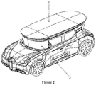
- Figure 2 is a schematic diagram of a solar vehicle on which a movable plate is retracted according to an embodiment of the present disclosure.
- the laterally deployable photovoltaic device according to the embodiment of the present disclosure includes at least one movable plate 2 on which a solar cell module is arranged and a rotation drive apparatus which fixedly connects the movable plate 2 to a vehicle body 3.
- Figure 3 is a schematic diagram of a laterally deployable photovoltaic device in which a movable plate is deployed according to an embodiment of the present disclosure.
- Figure 4 is a schematic diagram of a laterally deployable photovoltaic device in which a movable plate is retracted according to an embodiment of the present disclosure.
- a rotation drive apparatus 4 includes a fixed end and a drive end. The rotation drive apparatus 4 is secured to the vehicle body 3 via the fixed end. The drive end of the rotation drive apparatus 4 is fixedly connected to the movable plate 2. The movable plate 2 is driven by the rotation drive apparatus 4 to rotate to a side of the vehicle body 3.
- the rotation drive apparatus 4 may be implemented in many ways, such as a motor, a cylinder, an oil cylinder and other power devices.
- the rotation drive apparatus 4 in the embodiment may be a motor.
- a fixed end of the motor may be fixedly connected to the vehicle body 3 via a screw and a bolt or may be soldered to the vehicle body 3.
- the drive end may be a rotating shaft of the motor.
- the motor drives the rotating shaft to rotate, thereby driving the movable plate 2 to laterally deploy and laterally retract the movable plate 2.
- the motor may be powered by energy converted from solar energy, thereby further effectively using solar energy.
- the laterally deployable photovoltaic device according to the embodiment of the present disclosure may be applied to the vehicle or may other devices which utilize solar energy.
- the movable plate When applied to the vehicle, the movable plate may be deployed to increase an effective area for collecting solar energy.
- the rotation drive apparatus 4 is further configured to drive the movable plate 2 to rotate to retract the movable plate 2 from the side of the vehicle body 3.
- the movable plate is retracted under control of the rotation drive apparatus when the solar vehicle travels so as not to affect travel of the vehicle.
- the photovoltaic device further includes a fixed plate 1 on which a solar cell module is arranged.
- the above rotation drive apparatus 4 may drive the movable plate 2 to rotate to retract the movable plate 2 from the side of the vehicle body 3 to a position under the fixed plate 1.
- the fixed plate 1 may be configured such that the fixed plate 1 absorbs solar energy together with the movable plate 2 when the movable plate 2 is deployed, thereby further improving solar energy collection capability of the solar vehicle.
- the number of the movable plate 2 may be one or more than one.
- 4 movable plates 2 are provided. After the rotation drive apparatus 4 drives the movable plate 2 to rotate to retract the movable plate 2 from the side of the vehicle body, the more than one movable plate 2 may be arranged to overlap with each other, such that the vehicle occupies smaller space when the vehicle stops travelling.
- the laterally deployable photovoltaic device further includes a height adjusting apparatus which is configured to adjust a height of the movable plate 2 relative to the vehicle body 3.
- a fixed end of the height adjusting apparatus is fixedly connected to the vehicle body 3, and a height adjusting end of the height adjusting apparatus is fixedly connected to the movable plate 2.
- the height adjusting apparatus may be implemented by an elevating cylinder.
- the laterally deployable photovoltaic device may further include a flipping apparatus which is configured to adjust an angle of the movable plate 2 relative to the vehicle body 3.
- a fixed end of the flipping apparatus is fixedly connected to the vehicle body 3, and a flipping adjusting end of the flipping apparatus is fixedly connected to the movable plate 2.
- the flipping apparatus may be implemented by a flipping cylinder.
- a flipping angle of the movable plate 2 may be adjusted in different parts of the day such that the movable plate can receive solar energy with a maximum area.
- a solar vehicle is further provided in the embodiment of the present disclosure.
- the solar vehicle includes the laterally deployable photovoltaic device provided according to any one of the embodiments of the present disclosure, where the photovoltaic device is located on the roof of the solar vehicle.
- the roof of the solar vehicle is provided a solar cell module.
- the solar cell module on the roof of the vehicle and the solar cell module on the movable plate 2 may absorb solar energy together to increase an absorption rate of solar energy.
- the roof may not be provided with the solar cell module and only the fixed plate 1 is provided with the solar cell module. In this way, in a case where the movable plate 2 is retracted, solar energy may be absorbed through the solar cell module on the fixed plate 1.
Landscapes
- Engineering & Computer Science (AREA)
- Mechanical Engineering (AREA)
- Transportation (AREA)
- Power Engineering (AREA)
- Chemical & Material Sciences (AREA)
- Combustion & Propulsion (AREA)
- Photovoltaic Devices (AREA)
- Body Structure For Vehicles (AREA)
- Arrangement Or Mounting Of Propulsion Units For Vehicles (AREA)
Abstract
Description
- The present application claims the priority to Chinese Patent Application No.
201720585146.6 - The present disclosure relates to the technical field of new energy vehicles, and in particular to a laterally deployable photovoltaic device and a solar vehicle.
- Solar vehicles are new energy vehicles which integrate solar cell modules which convert solar energy into electrical energy to drive the vehicles.
- For the traditional solar vehicle, an area on which a solar cell module can be arranged is limited due to the restriction on the vehicle structure, resulting in a relatively small amount of solar energy which can be collected by the solar vehicle. Therefore, electrical power converted from solar energy is limited and is far from the actual power requirement of the solar vehicle.
- It is an object of the present disclosure to provide a laterally deployable photovoltaic device and a solar vehicle, to solve the problem in the conventional technology and improve solar energy collection capability of a solar vehicle.
- A laterally deployable photovoltaic device is provided according to the present disclosure. The photovoltaic device includes at least one movable plate on which a solar cell module is arranged, a rotation drive apparatus which fixedly connects the movable plate to a vehicle body and a flipping apparatus.
- The rotation drive apparatus includes a fixed end and a drive end, and is secured to the vehicle body via the fixed end, the drive end of the rotation drive apparatus is fixedly connected to the movable plate, and the movable plate is driven by the rotation drive apparatus to rotate to a side of the vehicle body.
- A fixed end of the flipping apparatus is fixedly connected to the vehicle body, and a flipping adjusting end of the flipping apparatus is fixedly connected to the movable plate, for adjusting an angle of the movable plate relative to the vehicle body.
- In the above laterally deployable photovoltaic device, optionally, the rotation drive apparatus drives the movable plate to rotate to retract the movable plate from the side of the vehicle body.
- The above laterally deployable photovoltaic device, optionally, further includes a fixed plate on which a solar cell module is arranged. The rotation drive apparatus drives the movable plate to rotate to retract the movable plate from the side of the vehicle body to a position under the fixed plate.
- In the above laterally deployable photovoltaic device, optionally, the number of the movable plate is one or more than one.
- In the above laterally deployable photovoltaic device, optionally, the more than one movable plate is arranged to overlap with each other after the rotation drive apparatus drives the movable plate to rotate to retract the movable plate from the side of the vehicle body.
- In the above laterally deployable photovoltaic device, optionally, the rotation drive apparatus is a motor.
- The above laterally deployable photovoltaic device, optionally, further includes a height adjusting apparatus. A fixed end of the height adjusting apparatus is fixedly connected to the vehicle body, and a height adjusting end of the height adjusting apparatus is fixedly connected to the movable plate, for adjusting a height of the movable plate relative to the vehicle body.
- A solar vehicle is further provided according to the present disclosure. The solar vehicle includes the laterally deployable photovoltaic device according to the present disclosure. The photovoltaic device is arranged on a roof of the solar vehicle.
- In the above solar vehicle, optionally, the roof of the solar vehicle is provided with a solar cell module.
- In the laterally deployable photovoltaic device and the solar vehicle provided according to the present disclosure, the rotation drive apparatus and the movable plate are provided. The rotation drive apparatus drives the movable plate to deploy the movable plate on a side of the vehicle body when the solar vehicle stops travelling, to increase an effective area for collecting solar energy, and drives the movable plate to retract the movable plate when the solar vehicle travels so as not to affect travel of the vehicle. Compared with the conventional technology, the solar energy collection capability of the laterally deployable photovoltaic device and the solar vehicle provided according to the present disclosure is greatly improved.
-
-
Figure 1 is a schematic diagram of a solar vehicle on which a movable plate is deployed according to an embodiment of the present disclosure; -
Figure 2 is a schematic diagram of a solar vehicle on which a movable plate is retracted according to an embodiment of the present disclosure; -
Figure 3 is a schematic diagram of a laterally deployable photovoltaic device in which a movable plate is deployed according to an embodiment of the present disclosure; and -
Figure 4 is a schematic diagram of a laterally deployable photovoltaic device in which a movable plate is retracted according to an embodiment of the present disclosure. - Reference signs in the drawings are listed as follows:
1-fixed plate 2-movable plate 3-vehicle body 4-rotation drive apparatus - The embodiments of the present disclosure are described in detail hereinafter, and are illustrated in drawings, in which the same or similar reference signs represent the same or similar elements or elements with the same or similar functions throughout the description. The embodiments described in the following with reference to the drawings are only exemplary embodiments which are used to explain the present disclosure, and should not be construed to limit the present disclosure.
- A laterally deployable photovoltaic device is provided according to the embodiment of the present disclosure, which may be applied to a roof of a solar vehicle.
Figure 1 is a schematic diagram of a solar vehicle on which a movable plate is deployed according to an embodiment of the present disclosure.Figure 2 is a schematic diagram of a solar vehicle on which a movable plate is retracted according to an embodiment of the present disclosure. As shown inFigure 1 andFigure 2 , the laterally deployable photovoltaic device according to the embodiment of the present disclosure includes at least onemovable plate 2 on which a solar cell module is arranged and a rotation drive apparatus which fixedly connects themovable plate 2 to avehicle body 3. -
Figure 3 is a schematic diagram of a laterally deployable photovoltaic device in which a movable plate is deployed according to an embodiment of the present disclosure.Figure 4 is a schematic diagram of a laterally deployable photovoltaic device in which a movable plate is retracted according to an embodiment of the present disclosure. Reference is made toFigures 1 to 4 , arotation drive apparatus 4 includes a fixed end and a drive end. Therotation drive apparatus 4 is secured to thevehicle body 3 via the fixed end. The drive end of therotation drive apparatus 4 is fixedly connected to themovable plate 2. Themovable plate 2 is driven by therotation drive apparatus 4 to rotate to a side of thevehicle body 3. - The
rotation drive apparatus 4 may be implemented in many ways, such as a motor, a cylinder, an oil cylinder and other power devices. Optionally, therotation drive apparatus 4 in the embodiment may be a motor. A fixed end of the motor may be fixedly connected to thevehicle body 3 via a screw and a bolt or may be soldered to thevehicle body 3. The drive end may be a rotating shaft of the motor. The motor drives the rotating shaft to rotate, thereby driving themovable plate 2 to laterally deploy and laterally retract themovable plate 2. The motor may be powered by energy converted from solar energy, thereby further effectively using solar energy. - The laterally deployable photovoltaic device according to the embodiment of the present disclosure may be applied to the vehicle or may other devices which utilize solar energy. When applied to the vehicle, the movable plate may be deployed to increase an effective area for collecting solar energy.
- Optionally, the
rotation drive apparatus 4 is further configured to drive themovable plate 2 to rotate to retract themovable plate 2 from the side of thevehicle body 3. The movable plate is retracted under control of the rotation drive apparatus when the solar vehicle travels so as not to affect travel of the vehicle. - As a preferred implementation, the photovoltaic device further includes a
fixed plate 1 on which a solar cell module is arranged. The aboverotation drive apparatus 4 may drive themovable plate 2 to rotate to retract themovable plate 2 from the side of thevehicle body 3 to a position under thefixed plate 1. Thefixed plate 1 may be configured such that thefixed plate 1 absorbs solar energy together with themovable plate 2 when themovable plate 2 is deployed, thereby further improving solar energy collection capability of the solar vehicle. - Based on a design requirement, the number of the
movable plate 2 may be one or more than one. In the embodiment, 4movable plates 2 are provided. After therotation drive apparatus 4 drives themovable plate 2 to rotate to retract themovable plate 2 from the side of the vehicle body, the more than onemovable plate 2 may be arranged to overlap with each other, such that the vehicle occupies smaller space when the vehicle stops travelling. - Based on the above embodiment, the laterally deployable photovoltaic device according to the embodiment of the present disclosure further includes a height adjusting apparatus which is configured to adjust a height of the
movable plate 2 relative to thevehicle body 3. A fixed end of the height adjusting apparatus is fixedly connected to thevehicle body 3, and a height adjusting end of the height adjusting apparatus is fixedly connected to themovable plate 2. The height adjusting apparatus may be implemented by an elevating cylinder. When the solar vehicle is parked in a parking space, themovable plate 2 is elevated to a certain height through the height adjusting apparatus, thereby avoiding conflict with a vehicle in a neighboring parking space. - Furthermore, the laterally deployable photovoltaic device may further include a flipping apparatus which is configured to adjust an angle of the
movable plate 2 relative to thevehicle body 3. A fixed end of the flipping apparatus is fixedly connected to thevehicle body 3, and a flipping adjusting end of the flipping apparatus is fixedly connected to themovable plate 2. The flipping apparatus may be implemented by a flipping cylinder. A flipping angle of themovable plate 2 may be adjusted in different parts of the day such that the movable plate can receive solar energy with a maximum area. - A solar vehicle is further provided in the embodiment of the present disclosure. As shown in
Figure 1 andFigure 2 , the solar vehicle includes the laterally deployable photovoltaic device provided according to any one of the embodiments of the present disclosure, where the photovoltaic device is located on the roof of the solar vehicle. - Further, the roof of the solar vehicle is provided a solar cell module. After the
movable plate 2 rotates to be deployed, the solar cell module on the roof of the vehicle and the solar cell module on themovable plate 2 may absorb solar energy together to increase an absorption rate of solar energy. It should be understood by those skilled in the art that in a case where the above laterally deployable photovoltaic device includes the fixedplate 1, the roof may not be provided with the solar cell module and only the fixedplate 1 is provided with the solar cell module. In this way, in a case where themovable plate 2 is retracted, solar energy may be absorbed through the solar cell module on the fixedplate 1. - Structure, characteristics and effects of the present disclosure are described above in detail based on the embodiments illustrated in drawings. The embodiments described above are only preferred embodiments of the present disclosure. The present disclosure is not limited to the scope of implementation as illustrated by the drawings. Any simple changes, equivalents and modifications made to the embodiments based on the technical essence of the present disclosure without departing from the technical solution of the present disclosure fall within the protection scope of the technical solution of the present disclosure.
Claims (9)
- A laterally deployable photovoltaic device, comprising: at least one movable plate on which a solar cell module is arranged, a rotation drive apparatus which fixedly connects the movable plate to a vehicle body and a flipping apparatus; wherein
the rotation drive apparatus comprises a fixed end and a drive end, and is secured to the vehicle body via the fixed end, the drive end of the rotation drive apparatus is fixedly connected to the movable plate, and the movable plate is driven by the rotation drive apparatus to rotate to a side of the vehicle body; and
a fixed end of the flipping apparatus is fixedly connected to the vehicle body, and a flipping adjusting end of the flipping apparatus is fixedly connected to the movable plate, for adjusting an angle of the movable plate relative to the vehicle body. - The laterally deployable photovoltaic device according to claim 1, wherein the rotation drive apparatus drives the movable plate to rotate to retract the movable plate from the side of the vehicle body.
- The laterally deployable photovoltaic device according to any one of claims 1 to 2, further comprising: a fixed plate on which a solar cell module is arranged, wherein the rotation drive apparatus drives the movable plate to rotate to retract the movable plate from the side of the vehicle body to a position under the fixed plate.
- The laterally deployable photovoltaic device according to any one of claims 1 to 2, wherein the number of the movable plate is one or more than one.
- The laterally deployable photovoltaic device according claim 4, wherein the more than one movable plate is arranged to overlap with each other after the rotation drive apparatus drives the movable plate to rotate to retract the movable plate from the side of the vehicle body.
- The laterally deployable photovoltaic device according claim 1, wherein the rotation drive apparatus is a motor.
- The laterally deployable photovoltaic device according claim 1, further comprising a height adjusting apparatus, wherein a fixed end of the height adjusting apparatus is fixedly connected to the vehicle body, and a height adjusting end of the height adjusting apparatus is fixedly connected to the movable plate, for adjusting a height of the movable plate relative to the vehicle body.
- A solar vehicle, comprising the laterally deployable photovoltaic device according to any one of claims 1 to 7, wherein the photovoltaic device is arranged on a roof of the solar vehicle.
- The solar vehicle according to claim 8, wherein the roof of the solar vehicle is provided with a solar cell module.
Applications Claiming Priority (2)
| Application Number | Priority Date | Filing Date | Title |
|---|---|---|---|
| CN201720585146.6U CN206812807U (en) | 2017-05-24 | 2017-05-24 | The photovoltaic devices and solar telephone that can laterally deploy |
| PCT/CN2018/087110 WO2018214786A1 (en) | 2017-05-24 | 2018-05-16 | Laterally expandable photovoltaic device and solar powered automobile |
Publications (3)
| Publication Number | Publication Date |
|---|---|
| EP3431322A1 true EP3431322A1 (en) | 2019-01-23 |
| EP3431322A8 EP3431322A8 (en) | 2019-07-31 |
| EP3431322A4 EP3431322A4 (en) | 2019-09-18 |
Family
ID=60756145
Family Applications (1)
| Application Number | Title | Priority Date | Filing Date |
|---|---|---|---|
| EP18750305.7A Withdrawn EP3431322A4 (en) | 2017-05-24 | 2018-05-16 | PHOTOVOLTAIC DEVICE WITH SIDE EXTENSION AND AUTOMOTIVE WITH SOLAR ENERGY |
Country Status (11)
| Country | Link |
|---|---|
| US (1) | US20210188096A1 (en) |
| EP (1) | EP3431322A4 (en) |
| JP (1) | JP2019522451A (en) |
| KR (1) | KR20190087988A (en) |
| CN (1) | CN206812807U (en) |
| AU (1) | AU2018214115A1 (en) |
| BR (1) | BR212018069792U2 (en) |
| RU (1) | RU190498U1 (en) |
| SG (1) | SG11201806708YA (en) |
| WO (1) | WO2018214786A1 (en) |
| ZA (1) | ZA201805876B (en) |
Families Citing this family (14)
| Publication number | Priority date | Publication date | Assignee | Title |
|---|---|---|---|---|
| CN206812807U (en) * | 2017-05-24 | 2017-12-29 | 东汉新能源汽车技术有限公司 | The photovoltaic devices and solar telephone that can laterally deploy |
| CN108621806B (en) * | 2018-05-14 | 2019-11-01 | 福建三龙新能源汽车有限公司 | A kind of energy conservation intelligent electric vintage car |
| CN108749913B (en) * | 2018-05-30 | 2023-05-09 | 西安工业大学 | Solar walking vehicle |
| CN109035601A (en) * | 2018-07-27 | 2018-12-18 | 东汉新能源汽车技术有限公司 | Shared vehicle and its billing control method and state monitoring method |
| CN110936819A (en) * | 2018-09-21 | 2020-03-31 | 武汉华志机器人产业技术研究院有限公司 | Multi-power-source mechanism applied to transportation means |
| CN110936820A (en) * | 2018-09-21 | 2020-03-31 | 武汉华志机器人产业技术研究院有限公司 | Multi-power-source system applied to transportation tool |
| CN110936809A (en) * | 2018-09-21 | 2020-03-31 | 武汉华志机器人产业技术研究院有限公司 | Multi-power-source equipment |
| CN110936818A (en) * | 2018-09-21 | 2020-03-31 | 武汉华志机器人产业技术研究院有限公司 | Energy-saving system |
| US11410545B2 (en) * | 2019-07-19 | 2022-08-09 | Ford Global Technologies, Llc | Dynamic vehicle perimeter definition and reporting |
| CN110979020A (en) * | 2019-12-04 | 2020-04-10 | 秦皇岛博硕光电设备股份有限公司 | Solar cell power generation device for vehicle and retractable roof |
| CN114911283A (en) * | 2021-02-09 | 2022-08-16 | 天津城建大学 | Movable solar energy cold-hot electricity triple-generation intelligent trailer carriage |
| US20230173928A1 (en) * | 2021-12-03 | 2023-06-08 | George F. White, III | Photovoltaic Charging System for an Electric Vehicle Internal Battery |
| CN116208073B (en) * | 2022-09-09 | 2024-01-23 | 苏州吉弘能源科技有限公司 | Photovoltaic power generation system |
| CN117984796A (en) * | 2024-03-04 | 2024-05-07 | 吉林大学 | A deployable photovoltaic power generation device based on automobile |
Family Cites Families (27)
| Publication number | Priority date | Publication date | Assignee | Title |
|---|---|---|---|---|
| JPH01141160U (en) * | 1988-03-24 | 1989-09-27 | ||
| RU2053142C1 (en) * | 1992-11-10 | 1996-01-27 | Предприятие "ЭМ" | Heliomobile |
| US20080100258A1 (en) * | 2006-08-23 | 2008-05-01 | Ward Thomas A | Hybrid vehicle with adjustable modular solar panel to increase charge generation |
| RU2381426C2 (en) * | 2007-10-25 | 2010-02-10 | Открытое акционерное общество Завод "Красное знамя" | Turning device for solar power module |
| DE102008046798A1 (en) * | 2008-09-11 | 2010-03-18 | Schaeffler Kg | motor vehicle |
| US20100193260A1 (en) * | 2009-02-03 | 2010-08-05 | Benjamin Freeman | Electric car with maximized solar assist |
| US20100193261A1 (en) * | 2009-02-03 | 2010-08-05 | Benjamin David Freeman | Cost effective system for supplying solar electricity to both an extended range electric vehicle and a nearby building |
| CN102019856A (en) * | 2009-09-18 | 2011-04-20 | 马建民 | Solar energy powered electric automobile with wind-powered moving assistant |
| US20120073885A1 (en) * | 2010-09-23 | 2012-03-29 | Kenergy Development Corp. | Motorized vehicle with expanded solar panel capacity |
| CN202231036U (en) * | 2011-10-14 | 2012-05-23 | 河南光之源太阳能科技有限公司 | Automatic flip photoelectric panel for solar automobile |
| JP2013255405A (en) * | 2012-06-05 | 2013-12-19 | Pai Cho | Auxiliary charging device for electric vehicle |
| WO2014018015A1 (en) * | 2012-07-24 | 2014-01-30 | Empire Technology Development Llc | Stowable tracking photovoltaic array |
| US20140297072A1 (en) * | 2013-03-28 | 2014-10-02 | Benjamin David Freeman | Group of systems for making a solar electric vehicle more practical |
| CN203318153U (en) * | 2013-04-24 | 2013-12-04 | 王晓岚 | Solar electromobile device with four-directional self-unfolding wings |
| US20150075880A1 (en) * | 2013-09-13 | 2015-03-19 | GK Machine, Inc. | Electric cart for facilitating the harvesting of berries and other crops |
| CN105656407A (en) * | 2014-11-11 | 2016-06-08 | 西安银河网电智能电气有限公司 | Photovoltaic panel assembly of folding solar photovoltaic power generation mechanism for automobiles |
| CN204340714U (en) * | 2014-12-24 | 2015-05-20 | 湖州佳力机电科技有限公司 | A kind of solar electric vehicle with combined battery plate |
| CN204801530U (en) * | 2015-06-06 | 2015-11-25 | 曹智 | Energy -saving car |
| US10439549B2 (en) * | 2015-08-26 | 2019-10-08 | Ravi Nagarajarao KURLAGUNDA | Vehicle attached photovoltaic charging systems |
| CN205417211U (en) * | 2016-01-28 | 2016-08-03 | 中电海康集团有限公司 | Solar -energy charging device |
| CN205439921U (en) * | 2016-02-26 | 2016-08-10 | 温州市龙湾区职业技术学校 | Solar car of scalable expansion in both sides |
| CN205523727U (en) * | 2016-04-08 | 2016-08-31 | 北京创新纪技术开发有限公司 | Full angle solar energy dislocation generation car |
| CN205651965U (en) * | 2016-05-04 | 2016-10-19 | 江西共青城汉能薄膜太阳能有限公司 | Photovoltaic power generation device that new energy automobile used |
| CN205754180U (en) * | 2016-07-13 | 2016-11-30 | 浙江启鑫新能源科技股份有限公司 | For the solar panel to electric motor car energy storage |
| CN205853901U (en) * | 2016-08-16 | 2017-01-04 | 张明永 | A kind of solar panel for body of a motor car |
| CN205930263U (en) * | 2016-08-28 | 2017-02-08 | 山东国金汽车工程技术有限公司 | Electric automobile's portable solar charging panel |
| CN206812807U (en) * | 2017-05-24 | 2017-12-29 | 东汉新能源汽车技术有限公司 | The photovoltaic devices and solar telephone that can laterally deploy |
-
2017
- 2017-05-24 CN CN201720585146.6U patent/CN206812807U/en not_active Expired - Fee Related
-
2018
- 2018-05-16 SG SG11201806708YA patent/SG11201806708YA/en unknown
- 2018-05-16 BR BR212018069792-9U patent/BR212018069792U2/en not_active IP Right Cessation
- 2018-05-16 WO PCT/CN2018/087110 patent/WO2018214786A1/en not_active Ceased
- 2018-05-16 US US16/078,627 patent/US20210188096A1/en not_active Abandoned
- 2018-05-16 JP JP2018544359A patent/JP2019522451A/en active Pending
- 2018-05-16 AU AU2018214115A patent/AU2018214115A1/en not_active Abandoned
- 2018-05-16 RU RU2018134034U patent/RU190498U1/en not_active IP Right Cessation
- 2018-05-16 KR KR1020187024360A patent/KR20190087988A/en not_active Ceased
- 2018-05-16 EP EP18750305.7A patent/EP3431322A4/en not_active Withdrawn
- 2018-08-31 ZA ZA2018/05876A patent/ZA201805876B/en unknown
Also Published As
| Publication number | Publication date |
|---|---|
| SG11201806708YA (en) | 2018-12-28 |
| JP2019522451A (en) | 2019-08-08 |
| KR20190087988A (en) | 2019-07-25 |
| BR212018069792U2 (en) | 2020-03-10 |
| WO2018214786A1 (en) | 2018-11-29 |
| EP3431322A8 (en) | 2019-07-31 |
| CN206812807U (en) | 2017-12-29 |
| RU190498U1 (en) | 2019-07-02 |
| EP3431322A4 (en) | 2019-09-18 |
| AU2018214115A1 (en) | 2018-08-23 |
| ZA201805876B (en) | 2023-01-25 |
| US20210188096A1 (en) | 2021-06-24 |
Similar Documents
| Publication | Publication Date | Title |
|---|---|---|
| US20210188096A1 (en) | Laterally deployable photovoltaic device and solar vehicle | |
| CN106185716A (en) | A kind of vehicular unmanned plane lifting platform system | |
| CN207427064U (en) | A kind of photovoltaic module stretched automatically | |
| CN110936810A (en) | Improvement type new energy automobile | |
| CN105676876A (en) | Vehicle-mounted solar tracking power generation system | |
| HK40002485A (en) | Laterally expandable photovoltaic device and solar powered automobile | |
| CN206968411U (en) | The photovoltaic devices and solar telephone that can be moved forward | |
| DE202014005964U1 (en) | Traceable photovoltaic module | |
| CN207630988U (en) | Photovoltaic devices with function day by day and solar telephone | |
| CN221177623U (en) | Sun tracking device for photovoltaic module | |
| CN219420691U (en) | Supporting device of solar photovoltaic power generation plate | |
| CN112693304A (en) | Automatic tracking device for vehicle-mounted solar panel | |
| CN119401923A (en) | A steering device capable of adjusting the direction of a photovoltaic solar panel | |
| CN215360920U (en) | A vehicle-mounted solar panel automatic tracking device | |
| CN211172755U (en) | Green roof | |
| CN204506546U (en) | It is a kind of that vehicle-mounted sun charging board is structural dodges draw off gear | |
| CN206765806U (en) | The photovoltaic devices and solar telephone that can be moved rearwards | |
| CN105904472A (en) | Control method and device of mechanical arm for quickly approaching to solar panel | |
| CN217037096U (en) | Solar photovoltaic aluminum frame protection structure | |
| CN221190584U (en) | Wind turbine generator system yaw system snatchs tilting mechanism | |
| CN118849850B (en) | Photovoltaic energy storage charging pile and use method thereof | |
| CN220252452U (en) | Sun tracking device for solar power generation device | |
| CN112780085A (en) | Solar photovoltaic environment-friendly car shed | |
| CN115276557B (en) | A distributed photovoltaic measurement device that can be connected to the power grid and its use method | |
| CN207889506U (en) | A kind of Telescopic sun visor for car |
Legal Events
| Date | Code | Title | Description |
|---|---|---|---|
| STAA | Information on the status of an ep patent application or granted ep patent |
Free format text: STATUS: UNKNOWN |
|
| STAA | Information on the status of an ep patent application or granted ep patent |
Free format text: STATUS: THE INTERNATIONAL PUBLICATION HAS BEEN MADE |
|
| PUAI | Public reference made under article 153(3) epc to a published international application that has entered the european phase |
Free format text: ORIGINAL CODE: 0009012 |
|
| STAA | Information on the status of an ep patent application or granted ep patent |
Free format text: STATUS: REQUEST FOR EXAMINATION WAS MADE |
|
| 17P | Request for examination filed |
Effective date: 20180817 |
|
| AK | Designated contracting states |
Kind code of ref document: A1 Designated state(s): AL AT BE BG CH CY CZ DE DK EE ES FI FR GB GR HR HU IE IS IT LI LT LU LV MC MK MT NL NO PL PT RO RS SE SI SK SM TR |
|
| AX | Request for extension of the european patent |
Extension state: BA ME |
|
| RAP1 | Party data changed (applicant data changed or rights of an application transferred) |
Owner name: DONG HAN NEW ENERGY AUTOMOTIVE TECHNOLOGY CO., LTD |
|
| A4 | Supplementary search report drawn up and despatched |
Effective date: 20190820 |
|
| RIC1 | Information provided on ipc code assigned before grant |
Ipc: B60L 50/50 20190101ALI20190813BHEP Ipc: H02S 20/30 20140101ALI20190813BHEP Ipc: B60L 8/00 20060101AFI20190813BHEP Ipc: H02S 10/40 20140101ALI20190813BHEP Ipc: B60R 16/033 20060101ALI20190813BHEP Ipc: B60K 16/00 20060101ALI20190813BHEP |
|
| REG | Reference to a national code |
Ref country code: HK Ref legal event code: DE Ref document number: 40002485 Country of ref document: HK |
|
| DAV | Request for validation of the european patent (deleted) | ||
| DAX | Request for extension of the european patent (deleted) | ||
| STAA | Information on the status of an ep patent application or granted ep patent |
Free format text: STATUS: THE APPLICATION IS DEEMED TO BE WITHDRAWN |
|
| 18D | Application deemed to be withdrawn |
Effective date: 20200603 |
|
| REG | Reference to a national code |
Ref country code: HK Ref legal event code: WD Ref document number: 40002485 Country of ref document: HK |