EP3431032A1 - Robot surgical platform - Google Patents
Robot surgical platform Download PDFInfo
- Publication number
- EP3431032A1 EP3431032A1 EP18184849.0A EP18184849A EP3431032A1 EP 3431032 A1 EP3431032 A1 EP 3431032A1 EP 18184849 A EP18184849 A EP 18184849A EP 3431032 A1 EP3431032 A1 EP 3431032A1
- Authority
- EP
- European Patent Office
- Prior art keywords
- screw
- surgical
- location
- trajectory
- user
- Prior art date
- Legal status (The legal status is an assumption and is not a legal conclusion. Google has not performed a legal analysis and makes no representation as to the accuracy of the status listed.)
- Granted
Links
- 210000000988 bone and bone Anatomy 0.000 claims abstract description 146
- 239000007943 implant Substances 0.000 claims abstract description 127
- 239000012636 effector Substances 0.000 claims description 196
- 230000033001 locomotion Effects 0.000 claims description 124
- 238000002591 computed tomography Methods 0.000 claims description 116
- 238000003825 pressing Methods 0.000 claims description 45
- 230000000977 initiatory effect Effects 0.000 claims description 16
- 238000003780 insertion Methods 0.000 claims description 16
- 230000037431 insertion Effects 0.000 claims description 16
- 238000003384 imaging method Methods 0.000 abstract description 26
- 238000013170 computed tomography imaging Methods 0.000 abstract description 9
- 239000003550 marker Substances 0.000 description 100
- 238000000034 method Methods 0.000 description 70
- 238000002594 fluoroscopy Methods 0.000 description 44
- 210000003484 anatomy Anatomy 0.000 description 40
- 238000012795 verification Methods 0.000 description 40
- 239000003381 stabilizer Substances 0.000 description 28
- 230000008569 process Effects 0.000 description 26
- 230000006870 function Effects 0.000 description 24
- 238000001356 surgical procedure Methods 0.000 description 19
- 239000003826 tablet Substances 0.000 description 17
- 238000010586 diagram Methods 0.000 description 14
- 239000000523 sample Substances 0.000 description 13
- 238000004590 computer program Methods 0.000 description 11
- 238000004891 communication Methods 0.000 description 8
- 238000009826 distribution Methods 0.000 description 8
- 238000003860 storage Methods 0.000 description 8
- 241001631457 Cannula Species 0.000 description 7
- 238000003491 array Methods 0.000 description 7
- 238000012546 transfer Methods 0.000 description 7
- 230000006835 compression Effects 0.000 description 6
- 238000007906 compression Methods 0.000 description 6
- 238000007726 management method Methods 0.000 description 6
- 210000000115 thoracic cavity Anatomy 0.000 description 6
- 210000001519 tissue Anatomy 0.000 description 6
- 241000284156 Clerodendrum quadriloculare Species 0.000 description 5
- 230000008859 change Effects 0.000 description 5
- 230000007246 mechanism Effects 0.000 description 5
- 230000003287 optical effect Effects 0.000 description 5
- 238000000926 separation method Methods 0.000 description 5
- 230000009471 action Effects 0.000 description 4
- 238000003032 molecular docking Methods 0.000 description 4
- 238000012545 processing Methods 0.000 description 4
- 238000012360 testing method Methods 0.000 description 4
- 101710194177 Glutamate-methylamine ligase Proteins 0.000 description 3
- 230000010339 dilation Effects 0.000 description 3
- 230000000694 effects Effects 0.000 description 3
- 230000004807 localization Effects 0.000 description 3
- 239000000463 material Substances 0.000 description 3
- 239000002184 metal Substances 0.000 description 3
- 238000012986 modification Methods 0.000 description 3
- 230000004048 modification Effects 0.000 description 3
- 230000006641 stabilisation Effects 0.000 description 3
- 238000011105 stabilization Methods 0.000 description 3
- 230000000007 visual effect Effects 0.000 description 3
- 210000000707 wrist Anatomy 0.000 description 3
- 244000223072 Narcissus jonquilla Species 0.000 description 2
- 235000013862 Narcissus jonquilla Nutrition 0.000 description 2
- 208000003152 Yellow Fever Diseases 0.000 description 2
- 230000003213 activating effect Effects 0.000 description 2
- 238000013500 data storage Methods 0.000 description 2
- 230000000916 dilatatory effect Effects 0.000 description 2
- 210000003811 finger Anatomy 0.000 description 2
- 238000004519 manufacturing process Methods 0.000 description 2
- 239000013307 optical fiber Substances 0.000 description 2
- 230000000644 propagated effect Effects 0.000 description 2
- 239000007787 solid Substances 0.000 description 2
- 238000012800 visualization Methods 0.000 description 2
- 241001155961 Baris Species 0.000 description 1
- 239000004696 Poly ether ether ketone Substances 0.000 description 1
- 241000283984 Rodentia Species 0.000 description 1
- 244000090125 Solidago odora Species 0.000 description 1
- 241000700605 Viruses Species 0.000 description 1
- 238000010521 absorption reaction Methods 0.000 description 1
- 230000002411 adverse Effects 0.000 description 1
- 238000013459 approach Methods 0.000 description 1
- JUPQTSLXMOCDHR-UHFFFAOYSA-N benzene-1,4-diol;bis(4-fluorophenyl)methanone Chemical compound OC1=CC=C(O)C=C1.C1=CC(F)=CC=C1C(=O)C1=CC=C(F)C=C1 JUPQTSLXMOCDHR-UHFFFAOYSA-N 0.000 description 1
- 238000003339 best practice Methods 0.000 description 1
- 238000004364 calculation method Methods 0.000 description 1
- 239000003086 colorant Substances 0.000 description 1
- 238000001816 cooling Methods 0.000 description 1
- 230000001419 dependent effect Effects 0.000 description 1
- 238000005553 drilling Methods 0.000 description 1
- 230000009977 dual effect Effects 0.000 description 1
- 238000005516 engineering process Methods 0.000 description 1
- 238000007667 floating Methods 0.000 description 1
- 210000005224 forefinger Anatomy 0.000 description 1
- 230000004927 fusion Effects 0.000 description 1
- 210000004247 hand Anatomy 0.000 description 1
- 230000006872 improvement Effects 0.000 description 1
- 238000009434 installation Methods 0.000 description 1
- 230000003993 interaction Effects 0.000 description 1
- 239000010977 jade Substances 0.000 description 1
- 239000007788 liquid Substances 0.000 description 1
- 239000004973 liquid crystal related substance Substances 0.000 description 1
- 238000013507 mapping Methods 0.000 description 1
- 239000000203 mixture Substances 0.000 description 1
- 229920002530 polyetherether ketone Polymers 0.000 description 1
- 238000002360 preparation method Methods 0.000 description 1
- 238000012552 review Methods 0.000 description 1
- 238000005096 rolling process Methods 0.000 description 1
- 210000003131 sacroiliac joint Anatomy 0.000 description 1
- 238000009781 safety test method Methods 0.000 description 1
- 239000004065 semiconductor Substances 0.000 description 1
- 210000003625 skull Anatomy 0.000 description 1
- 238000001228 spectrum Methods 0.000 description 1
- 238000002672 stereotactic surgery Methods 0.000 description 1
- 230000001954 sterilising effect Effects 0.000 description 1
- 238000004659 sterilization and disinfection Methods 0.000 description 1
- 230000004083 survival effect Effects 0.000 description 1
- 210000003813 thumb Anatomy 0.000 description 1
Images


Classifications
-
- A—HUMAN NECESSITIES
- A61—MEDICAL OR VETERINARY SCIENCE; HYGIENE
- A61B—DIAGNOSIS; SURGERY; IDENTIFICATION
- A61B17/00—Surgical instruments, devices or methods, e.g. tourniquets
- A61B17/16—Bone cutting, breaking or removal means other than saws, e.g. Osteoclasts; Drills or chisels for bones; Trepans
- A61B17/1662—Bone cutting, breaking or removal means other than saws, e.g. Osteoclasts; Drills or chisels for bones; Trepans for particular parts of the body
- A61B17/1671—Bone cutting, breaking or removal means other than saws, e.g. Osteoclasts; Drills or chisels for bones; Trepans for particular parts of the body for the spine
-
- A—HUMAN NECESSITIES
- A61—MEDICAL OR VETERINARY SCIENCE; HYGIENE
- A61B—DIAGNOSIS; SURGERY; IDENTIFICATION
- A61B17/00—Surgical instruments, devices or methods, e.g. tourniquets
- A61B17/56—Surgical instruments or methods for treatment of bones or joints; Devices specially adapted therefor
-
- A—HUMAN NECESSITIES
- A61—MEDICAL OR VETERINARY SCIENCE; HYGIENE
- A61B—DIAGNOSIS; SURGERY; IDENTIFICATION
- A61B17/00—Surgical instruments, devices or methods, e.g. tourniquets
- A61B17/56—Surgical instruments or methods for treatment of bones or joints; Devices specially adapted therefor
- A61B17/58—Surgical instruments or methods for treatment of bones or joints; Devices specially adapted therefor for osteosynthesis, e.g. bone plates, screws, setting implements or the like
- A61B17/68—Internal fixation devices, including fasteners and spinal fixators, even if a part thereof projects from the skin
- A61B17/70—Spinal positioners or stabilisers ; Bone stabilisers comprising fluid filler in an implant
- A61B17/7001—Screws or hooks combined with longitudinal elements which do not contact vertebrae
-
- A—HUMAN NECESSITIES
- A61—MEDICAL OR VETERINARY SCIENCE; HYGIENE
- A61B—DIAGNOSIS; SURGERY; IDENTIFICATION
- A61B17/00—Surgical instruments, devices or methods, e.g. tourniquets
- A61B17/56—Surgical instruments or methods for treatment of bones or joints; Devices specially adapted therefor
- A61B17/58—Surgical instruments or methods for treatment of bones or joints; Devices specially adapted therefor for osteosynthesis, e.g. bone plates, screws, setting implements or the like
- A61B17/68—Internal fixation devices, including fasteners and spinal fixators, even if a part thereof projects from the skin
- A61B17/70—Spinal positioners or stabilisers ; Bone stabilisers comprising fluid filler in an implant
- A61B17/7074—Tools specially adapted for spinal fixation operations other than for bone removal or filler handling
- A61B17/7083—Tools for guidance or insertion of tethers, rod-to-anchor connectors, rod-to-rod connectors, or longitudinal elements
-
- A—HUMAN NECESSITIES
- A61—MEDICAL OR VETERINARY SCIENCE; HYGIENE
- A61B—DIAGNOSIS; SURGERY; IDENTIFICATION
- A61B34/00—Computer-aided surgery; Manipulators or robots specially adapted for use in surgery
- A61B34/10—Computer-aided planning, simulation or modelling of surgical operations
-
- A—HUMAN NECESSITIES
- A61—MEDICAL OR VETERINARY SCIENCE; HYGIENE
- A61B—DIAGNOSIS; SURGERY; IDENTIFICATION
- A61B34/00—Computer-aided surgery; Manipulators or robots specially adapted for use in surgery
- A61B34/20—Surgical navigation systems; Devices for tracking or guiding surgical instruments, e.g. for frameless stereotaxis
-
- A—HUMAN NECESSITIES
- A61—MEDICAL OR VETERINARY SCIENCE; HYGIENE
- A61B—DIAGNOSIS; SURGERY; IDENTIFICATION
- A61B34/00—Computer-aided surgery; Manipulators or robots specially adapted for use in surgery
- A61B34/25—User interfaces for surgical systems
-
- A—HUMAN NECESSITIES
- A61—MEDICAL OR VETERINARY SCIENCE; HYGIENE
- A61B—DIAGNOSIS; SURGERY; IDENTIFICATION
- A61B34/00—Computer-aided surgery; Manipulators or robots specially adapted for use in surgery
- A61B34/30—Surgical robots
-
- A—HUMAN NECESSITIES
- A61—MEDICAL OR VETERINARY SCIENCE; HYGIENE
- A61B—DIAGNOSIS; SURGERY; IDENTIFICATION
- A61B34/00—Computer-aided surgery; Manipulators or robots specially adapted for use in surgery
- A61B34/70—Manipulators specially adapted for use in surgery
-
- A—HUMAN NECESSITIES
- A61—MEDICAL OR VETERINARY SCIENCE; HYGIENE
- A61B—DIAGNOSIS; SURGERY; IDENTIFICATION
- A61B34/00—Computer-aided surgery; Manipulators or robots specially adapted for use in surgery
- A61B34/70—Manipulators specially adapted for use in surgery
- A61B34/71—Manipulators operated by drive cable mechanisms
-
- A—HUMAN NECESSITIES
- A61—MEDICAL OR VETERINARY SCIENCE; HYGIENE
- A61B—DIAGNOSIS; SURGERY; IDENTIFICATION
- A61B34/00—Computer-aided surgery; Manipulators or robots specially adapted for use in surgery
- A61B34/70—Manipulators specially adapted for use in surgery
- A61B34/74—Manipulators with manual electric input means
-
- A—HUMAN NECESSITIES
- A61—MEDICAL OR VETERINARY SCIENCE; HYGIENE
- A61B—DIAGNOSIS; SURGERY; IDENTIFICATION
- A61B6/00—Apparatus for radiation diagnosis, e.g. combined with radiation therapy equipment
- A61B6/48—Diagnostic techniques
- A61B6/486—Diagnostic techniques involving generating temporal series of image data
- A61B6/487—Diagnostic techniques involving generating temporal series of image data involving fluoroscopy
-
- A—HUMAN NECESSITIES
- A61—MEDICAL OR VETERINARY SCIENCE; HYGIENE
- A61B—DIAGNOSIS; SURGERY; IDENTIFICATION
- A61B6/00—Apparatus for radiation diagnosis, e.g. combined with radiation therapy equipment
- A61B6/54—Control of apparatus or devices for radiation diagnosis
- A61B6/547—Control of apparatus or devices for radiation diagnosis involving tracking of position of the device or parts of the device
-
- A—HUMAN NECESSITIES
- A61—MEDICAL OR VETERINARY SCIENCE; HYGIENE
- A61B—DIAGNOSIS; SURGERY; IDENTIFICATION
- A61B90/00—Instruments, implements or accessories specially adapted for surgery or diagnosis and not covered by any of the groups A61B1/00 - A61B50/00, e.g. for luxation treatment or for protecting wound edges
- A61B90/36—Image-producing devices or illumination devices not otherwise provided for
- A61B90/37—Surgical systems with images on a monitor during operation
-
- G—PHYSICS
- G06—COMPUTING; CALCULATING OR COUNTING
- G06F—ELECTRIC DIGITAL DATA PROCESSING
- G06F3/00—Input arrangements for transferring data to be processed into a form capable of being handled by the computer; Output arrangements for transferring data from processing unit to output unit, e.g. interface arrangements
- G06F3/01—Input arrangements or combined input and output arrangements for interaction between user and computer
- G06F3/048—Interaction techniques based on graphical user interfaces [GUI]
- G06F3/0487—Interaction techniques based on graphical user interfaces [GUI] using specific features provided by the input device, e.g. functions controlled by the rotation of a mouse with dual sensing arrangements, or of the nature of the input device, e.g. tap gestures based on pressure sensed by a digitiser
- G06F3/0488—Interaction techniques based on graphical user interfaces [GUI] using specific features provided by the input device, e.g. functions controlled by the rotation of a mouse with dual sensing arrangements, or of the nature of the input device, e.g. tap gestures based on pressure sensed by a digitiser using a touch-screen or digitiser, e.g. input of commands through traced gestures
-
- G—PHYSICS
- G06—COMPUTING; CALCULATING OR COUNTING
- G06T—IMAGE DATA PROCESSING OR GENERATION, IN GENERAL
- G06T19/00—Manipulating 3D models or images for computer graphics
- G06T19/006—Mixed reality
-
- G—PHYSICS
- G16—INFORMATION AND COMMUNICATION TECHNOLOGY [ICT] SPECIALLY ADAPTED FOR SPECIFIC APPLICATION FIELDS
- G16H—HEALTHCARE INFORMATICS, i.e. INFORMATION AND COMMUNICATION TECHNOLOGY [ICT] SPECIALLY ADAPTED FOR THE HANDLING OR PROCESSING OF MEDICAL OR HEALTHCARE DATA
- G16H30/00—ICT specially adapted for the handling or processing of medical images
- G16H30/20—ICT specially adapted for the handling or processing of medical images for handling medical images, e.g. DICOM, HL7 or PACS
-
- G—PHYSICS
- G16—INFORMATION AND COMMUNICATION TECHNOLOGY [ICT] SPECIALLY ADAPTED FOR SPECIFIC APPLICATION FIELDS
- G16H—HEALTHCARE INFORMATICS, i.e. INFORMATION AND COMMUNICATION TECHNOLOGY [ICT] SPECIALLY ADAPTED FOR THE HANDLING OR PROCESSING OF MEDICAL OR HEALTHCARE DATA
- G16H40/00—ICT specially adapted for the management or administration of healthcare resources or facilities; ICT specially adapted for the management or operation of medical equipment or devices
- G16H40/60—ICT specially adapted for the management or administration of healthcare resources or facilities; ICT specially adapted for the management or operation of medical equipment or devices for the operation of medical equipment or devices
- G16H40/63—ICT specially adapted for the management or administration of healthcare resources or facilities; ICT specially adapted for the management or operation of medical equipment or devices for the operation of medical equipment or devices for local operation
-
- A—HUMAN NECESSITIES
- A61—MEDICAL OR VETERINARY SCIENCE; HYGIENE
- A61B—DIAGNOSIS; SURGERY; IDENTIFICATION
- A61B17/00—Surgical instruments, devices or methods, e.g. tourniquets
- A61B2017/00017—Electrical control of surgical instruments
- A61B2017/00199—Electrical control of surgical instruments with a console, e.g. a control panel with a display
-
- A—HUMAN NECESSITIES
- A61—MEDICAL OR VETERINARY SCIENCE; HYGIENE
- A61B—DIAGNOSIS; SURGERY; IDENTIFICATION
- A61B34/00—Computer-aided surgery; Manipulators or robots specially adapted for use in surgery
- A61B34/10—Computer-aided planning, simulation or modelling of surgical operations
- A61B2034/101—Computer-aided simulation of surgical operations
- A61B2034/102—Modelling of surgical devices, implants or prosthesis
-
- A—HUMAN NECESSITIES
- A61—MEDICAL OR VETERINARY SCIENCE; HYGIENE
- A61B—DIAGNOSIS; SURGERY; IDENTIFICATION
- A61B34/00—Computer-aided surgery; Manipulators or robots specially adapted for use in surgery
- A61B34/10—Computer-aided planning, simulation or modelling of surgical operations
- A61B2034/107—Visualisation of planned trajectories or target regions
-
- A—HUMAN NECESSITIES
- A61—MEDICAL OR VETERINARY SCIENCE; HYGIENE
- A61B—DIAGNOSIS; SURGERY; IDENTIFICATION
- A61B34/00—Computer-aided surgery; Manipulators or robots specially adapted for use in surgery
- A61B34/10—Computer-aided planning, simulation or modelling of surgical operations
- A61B2034/108—Computer aided selection or customisation of medical implants or cutting guides
-
- A—HUMAN NECESSITIES
- A61—MEDICAL OR VETERINARY SCIENCE; HYGIENE
- A61B—DIAGNOSIS; SURGERY; IDENTIFICATION
- A61B34/00—Computer-aided surgery; Manipulators or robots specially adapted for use in surgery
- A61B34/20—Surgical navigation systems; Devices for tracking or guiding surgical instruments, e.g. for frameless stereotaxis
- A61B2034/2046—Tracking techniques
- A61B2034/2055—Optical tracking systems
- A61B2034/2057—Details of tracking cameras
-
- A—HUMAN NECESSITIES
- A61—MEDICAL OR VETERINARY SCIENCE; HYGIENE
- A61B—DIAGNOSIS; SURGERY; IDENTIFICATION
- A61B34/00—Computer-aided surgery; Manipulators or robots specially adapted for use in surgery
- A61B34/20—Surgical navigation systems; Devices for tracking or guiding surgical instruments, e.g. for frameless stereotaxis
- A61B2034/2046—Tracking techniques
- A61B2034/2065—Tracking using image or pattern recognition
-
- A—HUMAN NECESSITIES
- A61—MEDICAL OR VETERINARY SCIENCE; HYGIENE
- A61B—DIAGNOSIS; SURGERY; IDENTIFICATION
- A61B34/00—Computer-aided surgery; Manipulators or robots specially adapted for use in surgery
- A61B34/20—Surgical navigation systems; Devices for tracking or guiding surgical instruments, e.g. for frameless stereotaxis
- A61B2034/2068—Surgical navigation systems; Devices for tracking or guiding surgical instruments, e.g. for frameless stereotaxis using pointers, e.g. pointers having reference marks for determining coordinates of body points
- A61B2034/207—Divots for calibration
-
- A—HUMAN NECESSITIES
- A61—MEDICAL OR VETERINARY SCIENCE; HYGIENE
- A61B—DIAGNOSIS; SURGERY; IDENTIFICATION
- A61B34/00—Computer-aided surgery; Manipulators or robots specially adapted for use in surgery
- A61B34/20—Surgical navigation systems; Devices for tracking or guiding surgical instruments, e.g. for frameless stereotaxis
- A61B2034/2072—Reference field transducer attached to an instrument or patient
-
- A—HUMAN NECESSITIES
- A61—MEDICAL OR VETERINARY SCIENCE; HYGIENE
- A61B—DIAGNOSIS; SURGERY; IDENTIFICATION
- A61B34/00—Computer-aided surgery; Manipulators or robots specially adapted for use in surgery
- A61B34/25—User interfaces for surgical systems
- A61B2034/252—User interfaces for surgical systems indicating steps of a surgical procedure
-
- A—HUMAN NECESSITIES
- A61—MEDICAL OR VETERINARY SCIENCE; HYGIENE
- A61B—DIAGNOSIS; SURGERY; IDENTIFICATION
- A61B34/00—Computer-aided surgery; Manipulators or robots specially adapted for use in surgery
- A61B34/25—User interfaces for surgical systems
- A61B2034/254—User interfaces for surgical systems being adapted depending on the stage of the surgical procedure
-
- A—HUMAN NECESSITIES
- A61—MEDICAL OR VETERINARY SCIENCE; HYGIENE
- A61B—DIAGNOSIS; SURGERY; IDENTIFICATION
- A61B34/00—Computer-aided surgery; Manipulators or robots specially adapted for use in surgery
- A61B34/25—User interfaces for surgical systems
- A61B2034/256—User interfaces for surgical systems having a database of accessory information, e.g. including context sensitive help or scientific articles
-
- A—HUMAN NECESSITIES
- A61—MEDICAL OR VETERINARY SCIENCE; HYGIENE
- A61B—DIAGNOSIS; SURGERY; IDENTIFICATION
- A61B34/00—Computer-aided surgery; Manipulators or robots specially adapted for use in surgery
- A61B34/30—Surgical robots
- A61B2034/304—Surgical robots including a freely orientable platform, e.g. so called 'Stewart platforms'
-
- A—HUMAN NECESSITIES
- A61—MEDICAL OR VETERINARY SCIENCE; HYGIENE
- A61B—DIAGNOSIS; SURGERY; IDENTIFICATION
- A61B34/00—Computer-aided surgery; Manipulators or robots specially adapted for use in surgery
- A61B34/30—Surgical robots
- A61B2034/305—Details of wrist mechanisms at distal ends of robotic arms
-
- A—HUMAN NECESSITIES
- A61—MEDICAL OR VETERINARY SCIENCE; HYGIENE
- A61B—DIAGNOSIS; SURGERY; IDENTIFICATION
- A61B90/00—Instruments, implements or accessories specially adapted for surgery or diagnosis and not covered by any of the groups A61B1/00 - A61B50/00, e.g. for luxation treatment or for protecting wound edges
- A61B90/36—Image-producing devices or illumination devices not otherwise provided for
- A61B2090/363—Use of fiducial points
-
- A—HUMAN NECESSITIES
- A61—MEDICAL OR VETERINARY SCIENCE; HYGIENE
- A61B—DIAGNOSIS; SURGERY; IDENTIFICATION
- A61B90/00—Instruments, implements or accessories specially adapted for surgery or diagnosis and not covered by any of the groups A61B1/00 - A61B50/00, e.g. for luxation treatment or for protecting wound edges
- A61B90/36—Image-producing devices or illumination devices not otherwise provided for
- A61B2090/364—Correlation of different images or relation of image positions in respect to the body
- A61B2090/365—Correlation of different images or relation of image positions in respect to the body augmented reality, i.e. correlating a live optical image with another image
-
- A—HUMAN NECESSITIES
- A61—MEDICAL OR VETERINARY SCIENCE; HYGIENE
- A61B—DIAGNOSIS; SURGERY; IDENTIFICATION
- A61B90/00—Instruments, implements or accessories specially adapted for surgery or diagnosis and not covered by any of the groups A61B1/00 - A61B50/00, e.g. for luxation treatment or for protecting wound edges
- A61B90/36—Image-producing devices or illumination devices not otherwise provided for
- A61B90/37—Surgical systems with images on a monitor during operation
- A61B2090/371—Surgical systems with images on a monitor during operation with simultaneous use of two cameras
-
- A—HUMAN NECESSITIES
- A61—MEDICAL OR VETERINARY SCIENCE; HYGIENE
- A61B—DIAGNOSIS; SURGERY; IDENTIFICATION
- A61B90/00—Instruments, implements or accessories specially adapted for surgery or diagnosis and not covered by any of the groups A61B1/00 - A61B50/00, e.g. for luxation treatment or for protecting wound edges
- A61B90/36—Image-producing devices or illumination devices not otherwise provided for
- A61B90/37—Surgical systems with images on a monitor during operation
- A61B2090/376—Surgical systems with images on a monitor during operation using X-rays, e.g. fluoroscopy
- A61B2090/3762—Surgical systems with images on a monitor during operation using X-rays, e.g. fluoroscopy using computed tomography systems [CT]
-
- A—HUMAN NECESSITIES
- A61—MEDICAL OR VETERINARY SCIENCE; HYGIENE
- A61B—DIAGNOSIS; SURGERY; IDENTIFICATION
- A61B90/00—Instruments, implements or accessories specially adapted for surgery or diagnosis and not covered by any of the groups A61B1/00 - A61B50/00, e.g. for luxation treatment or for protecting wound edges
- A61B90/39—Markers, e.g. radio-opaque or breast lesions markers
- A61B2090/3937—Visible markers
-
- A—HUMAN NECESSITIES
- A61—MEDICAL OR VETERINARY SCIENCE; HYGIENE
- A61B—DIAGNOSIS; SURGERY; IDENTIFICATION
- A61B90/00—Instruments, implements or accessories specially adapted for surgery or diagnosis and not covered by any of the groups A61B1/00 - A61B50/00, e.g. for luxation treatment or for protecting wound edges
- A61B90/39—Markers, e.g. radio-opaque or breast lesions markers
- A61B2090/3983—Reference marker arrangements for use with image guided surgery
-
- A—HUMAN NECESSITIES
- A61—MEDICAL OR VETERINARY SCIENCE; HYGIENE
- A61B—DIAGNOSIS; SURGERY; IDENTIFICATION
- A61B2560/00—Constructional details of operational features of apparatus; Accessories for medical measuring apparatus
- A61B2560/04—Constructional details of apparatus
- A61B2560/0475—Special features of memory means, e.g. removable memory cards
-
- A—HUMAN NECESSITIES
- A61—MEDICAL OR VETERINARY SCIENCE; HYGIENE
- A61B—DIAGNOSIS; SURGERY; IDENTIFICATION
- A61B90/00—Instruments, implements or accessories specially adapted for surgery or diagnosis and not covered by any of the groups A61B1/00 - A61B50/00, e.g. for luxation treatment or for protecting wound edges
- A61B90/10—Instruments, implements or accessories specially adapted for surgery or diagnosis and not covered by any of the groups A61B1/00 - A61B50/00, e.g. for luxation treatment or for protecting wound edges for stereotaxic surgery, e.g. frame-based stereotaxis
- A61B90/11—Instruments, implements or accessories specially adapted for surgery or diagnosis and not covered by any of the groups A61B1/00 - A61B50/00, e.g. for luxation treatment or for protecting wound edges for stereotaxic surgery, e.g. frame-based stereotaxis with guides for needles or instruments, e.g. arcuate slides or ball joints
- A61B90/13—Instruments, implements or accessories specially adapted for surgery or diagnosis and not covered by any of the groups A61B1/00 - A61B50/00, e.g. for luxation treatment or for protecting wound edges for stereotaxic surgery, e.g. frame-based stereotaxis with guides for needles or instruments, e.g. arcuate slides or ball joints guided by light, e.g. laser pointers
-
- B—PERFORMING OPERATIONS; TRANSPORTING
- B25—HAND TOOLS; PORTABLE POWER-DRIVEN TOOLS; MANIPULATORS
- B25J—MANIPULATORS; CHAMBERS PROVIDED WITH MANIPULATION DEVICES
- B25J9/00—Programme-controlled manipulators
- B25J9/0009—Constructional details, e.g. manipulator supports, bases
- B25J9/0021—All motors in base
-
- B—PERFORMING OPERATIONS; TRANSPORTING
- B25—HAND TOOLS; PORTABLE POWER-DRIVEN TOOLS; MANIPULATORS
- B25J—MANIPULATORS; CHAMBERS PROVIDED WITH MANIPULATION DEVICES
- B25J9/00—Programme-controlled manipulators
- B25J9/06—Programme-controlled manipulators characterised by multi-articulated arms
Abstract
Description
- This application claims priority under 35 U.S.C. 119(e) to
U.S. Provisional Patent Application Serial No. 62/535,591, filed July 21, 2017 - The present disclosure relates to medical devices, and more particularly, robotic surgical systems and related methods and devices.
- Various medical procedures require the precise localization of a three-dimensional position of a surgical instrument within the body of a patient in order to effect optimized treatment. For example, some surgical procedures to fuse vertebrae require that a surgeon drill multiple holes into the bone structure at specific locations. To achieve high levels of mechanical integrity in the fusing system, and to balance the forces created in the bone structure, it is necessary that the holes are drilled precisely at desired locations. Vertebrae, like most bone structures, have complex shapes made up of non-planar curved surfaces making precise and perpendicular drilling difficult. Conventionally, a surgeon manually holds and positions a drill guide tube by using a guidance system to overlay the drill tube's position onto a three dimensional image of the bone structure. This manual process is both tedious and time consuming. The success of the surgery is largely dependent upon the dexterity of the surgeon who performs it.
- Robot surgical platforms are being introduced that can assist surgeons with positioning surgical tools and performing surgical procedures within a patient body. A robot surgical platform can include a robot that is coupled to an end-effector element, and where the robot is configured to control movement and positioning of the end-effector relative to the body. The end-effector may be a surgical tool guide tube, such as a drill guide tube, or may be the surgical tool itself.
- There is a need for a robot surgical platform that provides accurate localization of a three-dimensional position of a surgical tool relative to the body in order to effect optimized treatment. Improved localization accuracy can minimize human and robotic error while allowing fast and efficient surgical process. The ability to perform operations on a patient with a robot surgical platform and computer software can enhance the overall surgical procedure and the results achieved for the patient.
- Some embodiments of the present disclosure are directed to a surgical implant planning computer that can be used for intra-operative computed tomography (CT) imaging workflow. The surgical implant planning computer includes at least one network interface, a display device, at least one processor, and at least one memory. The at least one network interface is connectable to a CT image scanner and to a robot having a robot base coupled to a robot arm that is movable by motors relative to the robot base. The at least one memory stores program code that is executed by the at least one processor to perform operations that include displaying on the display device a CT image of a bone that is received from the CT image scanner through the at least one network interface and receiving a user's selection of a surgical screw from among a set of defined surgical screws. The operations further include displaying a graphical screw representing the selected surgical screw as an overlay on the CT image of the bone and controlling angular orientation and location of the displayed graphical screw relative to the bone in the CT image responsive to receipt of user inputs. An indication of the selected surgical screw and an angular orientation and a location of the displayed graphical screw are stored in a surgical plan data structure responsive to receipt of a defined user input.
- Some other embodiments of the present disclosure are directed to a surgical implant planning computer that can be used for pre-operative CT imaging workflow. The surgical implant planning computer includes at least one network interface, a display device, at least one processor, and at least one memory. The at least one network interface is connectable to an image database. The at least one memory stores program code that is executed by the at least one processor to perform operations that include loading a CT image of a bone, which is received from the image database through the at least one network interface, into the at least one memory. The operations display displaying the CT image on the display device. The operations receive a user's selection of a surgical screw from among a set of defined surgical screws, and display a graphical screw representing the selected surgical screw as an overlay on the CT image of the bone. The operations control angular orientation and location of the displayed graphical screw relative to the bone in the CT image responsive to receipt of user inputs, and store an indication of the selected surgical screw and an angular orientation and a location of the displayed graphical screw in a surgical plan data structure responsive to user input, the surgical plan data structure being configured for use by a robot with a robot base coupled to a robot arm that is movable by motors relative to the robot base.
- Some other embodiments of the present disclosure are directed to a surgical implant planning computer that can be used for fluoroscopic imaging workflow. The surgical implant planning computer includes at least one network interface, a display device, at least one processor, and at least one memory. The at least one network interface is connectable to a fluoroscopy imager, a marker tracking camera, and a robot having a robot base that is coupled to a robot arm which movable by motors relative to the robot base. The at least one memory stores program code that is executed by the at least one processor to perform operations that include performing a registration setup mode that includes determining occurrence of a first condition indicating the marker tracking camera can observe to track reflective markers that are attached to a fluoroscopy registration fixture of a fluoroscopy imager, and determining occurrence of a second condition indicating the marker tracking camera can observe to track dynamic reference base markers attached to the robot arm and/or an end-effector connected to the robot arm. While both of the first and second conditions are determined to continue to occur, the at least one processor allows operations to be performed to obtain a first intra-operative fluoroscopic image of a patient along a first plane and to obtain a second intra-operative fluoroscopic image of the patient along a second plane that is orthogonal to the first plane.
- Corresponding methods and computer program products are disclosed.
- Still other surgical implant landing computers, methods, and computer program products according to embodiments of the inventive subject matter will be or become apparent to one with skill in the art upon review of the following drawings and detailed description. It is intended that all such surgical implant landing computers, methods, and computer program products be included within this description, be within the scope of the present inventive subject matter, and be protected by the accompanying claims. Moreover, it is intended that all embodiments disclosed herein can be implemented separately or combined in any way and/or combination.
- According to a further example of the invention it is provided a surgical implant planning computer comprising: at least one network interface connectable to an image database; a display device; at least one processor; and at least one memory storing program code that is executed by the at least one processor to perform operations comprising: loading a computed tomography (CT) image of a bone, which is received from the image database through the at least one network interface, into the at least one memory; displaying the CT image on the display device; receiving a user's selection of a surgical screw from among a set of defined surgical screws; displaying a graphical screw representing the selected surgical screw as an overlay on the CT image of the bone; controlling angular orientation and location of the displayed graphical screw relative to the bone in the CT image responsive to receipt of user inputs; and storing an indication of the selected surgical screw and an angular orientation and a location of the displayed graphical screw in a surgical plan data structure responsive to user input, the surgical plan data structure being configured for use by a robot with a robot base coupled to a robot arm that is movable by motors relative to the robot base.
- In a version the operations to display the graphical screw representing the selected surgical screw as an overlay on the CT image of the bone, comprise: determining a trajectory along an axis of the graphical screw; and displaying a trajectory line that extends from adjacent to a tip of the graphical screw and along the trajectory to facilitate a user visually orienting and positioning the graphical screw relative to a desired insertion location on the bone.
- In another version the operations to control angular orientation and location of the displayed graphical screw relative to the bone in the CT image responsive to receipt of user inputs, comprise: translating a location of the displayed graphical screw responsive to determining that the user has pressed on a touch-sensitive screen of the display device over a screw body of the graphical screw while moving location of the user's continued pressing along the touch-sensitive screen; and angularly pivoting the displayed graphical screw responsive to determining that the user has pressed on the touch-sensitive screen over a screw head and/or tip of the graphical screw while moving location of the user's continued pressing along the touch-sensitive screen.
- Advantageously, the operations to control angular orientation and location of the displayed graphical screw relative to the bone in the CT image responsive to receipt of user inputs, comprise: selecting a length of the displayed graphical screw from among a set of defined lengths for surgical screws responsive to determining that the user has pressed on a touch-sensitive screen of the display device over a screw tip or a screw head of the graphical screw while moving location of the user's continued pressing along the touch-sensitive screen a measured distance, wherein the selected length is stored in the surgical plan data structure.
- In a further version, the operations further comprise: controlling angular orientation and location of the displayed graphical screw responsive to the movement of the robot arm while the end-effector is positioned relative to the patient.
- In another version the operations further comprise: performing a registration setup mode comprising determining occurrence of a first condition indicating that a marker tracking camera can observe to track reflective markers that are on a fluoroscopy registration fixture, and further determining occurrence of a second condition indicating that the marker tracking camera can observe to track dynamic reference base markers attached to the robot arm and/or an end-effector connected to the robot arm; displaying on the display device an indication of when both of the first and second conditions occur; and determining that the registration setup mode is allowed to be marked satisfied when at least both of the first and second conditions are determined to occur.
- In a further version, the operations further comprise: while both of the first and second conditions are determined to continue to occur, allowing operations to be performed to obtain a first intra-operative fluoroscopic image of the patient along a first plane and to obtain a second intra-operative fluoroscopic image of the patient along a second plane that is orthogonal to the first plane; and determining that a registration mode is allowed to be marked satisfied when the first and second intra-operative fluoroscopic images have been obtained.
- In another version, the operations further comprise: displaying the first and second intra-operative fluoroscopic images on the display device; displaying the graphical screw as an overlay on both of the first and second intra-operative fluoroscopic images; controlling angular orientation and location of the displayed graphical screw relative to a bone in the first and second intra-operative fluoroscopic images responsive to receipt of user inputs.
- In another version, wherein the operations further comprise: determining when the angular orientation and location of the displayed graphical screw relative to the bone in the first and second intra-operative fluoroscopic images satisfies a registration rule for corresponding to the angular orientation and the location of the displayed graphical screw in the surgical plan data structure; and displaying on the display device an indication of when the registration rule is satisfied.
- In a further version, the operations further comprise: based on determining that the registration rule is satisfied, controlling the motors responsive to content of the surgical plan data structure to regulate movement of the robot arm while positioning the end-effector relative to the patient; and controlling angular orientation and location of the graphical screw that is displayed, responsive to the movement of the robot arm while the end-effector is positioned relative to the patient.
- According to a further example of the invention it is provided a surgical implant planning computer comprising: at least one network interface connectable to a fluoroscopy imager, a marker tracking camera, and a robot having a robot base coupled to a robot arm that is movable by motors relative to the robot base; a display device; at least one processor; and at least one memory storing program code that is executed by the at least one processor to perform operations comprising: performing a registration setup mode comprising determining occurrence of a first condition indicating the marker tracking camera can observe to track reflective markers that are on a fluoroscopy registration fixture of a fluoroscopy imager, and determining occurrence of a second condition indicating the marker tracking camera can observe to track dynamic reference base markers attached to the robot arm and/or an end-effector connected to the robot arm; and while both of the first and second conditions are determined to continue to occur, allowing operations to be performed to obtain a first intra-operative fluoroscopic image of a patient along a first plane and to obtain a second intra-operative fluoroscopic image of the patient along a second plane that is orthogonal to the first plane.
- In a version, the operations further comprise: displaying the first and second intra-operative fluoroscopic images on the display device; receiving a user's selection of a surgical screw from among a set of defined surgical screws displaying a graphical screw representing the selected surgical screw as an overlay on both of the first and second intra-operative fluoroscopic images; controlling angular orientation and location of the displayed graphical screw relative to a bone shown in the first and second intra-operative fluoroscopic images responsive to receipt of user inputs; and storing an indication of an angular orientation and a location of the displayed graphical screw in a surgical plan data structure responsive to receipt of a defined user input.
- In a further version, the operations to display the graphical screw representing the selected surgical screw as an overlay on both of the first and second intra-operative fluoroscopic images, comprise: determining a trajectory along an axis of the graphical screw; and displaying a trajectory line that extends from adjacent to a tip of the graphical screw and along the trajectory to facilitate a user visually orienting and positioning the graphical screw relative to a desired insertion location on the bone.
- In another version, the operations to control angular orientation and location of the displayed graphical screw relative to the bone shown in the first and second intra-operative fluoroscopic images responsive to receipt of user inputs, comprise: translating a location of the displayed graphical screw responsive to determining that the user has pressed on a touch-sensitive screen of the display device over a screw body of the graphical screw while moving location of the user's continued pressing along the touch-sensitive screen; and angularly pivoting the displayed graphical screw responsive to determining that the user has pressed on the touch-sensitive screen over a screw head and/or tip of the graphical screw while moving location of the user's continued pressing along the touch-sensitive screen.
- In another version, the operations to control angular orientation and location of the displayed graphical screw relative to the bone shown in the first and second intra-operative fluoroscopic images responsive to receipt of user inputs, comprise: selecting a length of the displayed graphical screw from among a set of defined lengths for surgical screws responsive to determining that the user has pressed on a touch-sensitive screen of the display device over a screw tip or a screw head of the graphical screw while moving location of the user's continued pressing along the touch-sensitive screen a measured distance, wherein the selected length is stored in the surgical plan data structure.
- In a further version, the operations further comprise: controlling the motors responsive to content of the surgical plan data structure to regulate movement of the robot arm while positioning the end-effector relative to a patient; and controlling angular orientation and location of the displayed graphical screw responsive to the movement of the robot arm while the end-effector is positioned relative to the patient.
- In another version, the operations further comprise: controlling the motors to move the end-effector in a direction along a trajectory defined by the content of the surgical plan data structure; and controlling location of the displayed graphical screw responsive to the movement of the end-effector along the trajectory.
- In a version, the operations further comprise: while moving the end-effector along the trajectory, further controlling the motors to resist movement of the end-effector in a direction perpendicular to the trajectory until another operation is perform that cancels an end-effector trajectory constraint mode.
- In a further version, the operations further comprise: prior to initiating the end-effector trajectory constraint mode, controlling the motors to move the end-effector in a direction upward away from the patient and then toward a location along the trajectory; preventing initiation of the end-effector trajectory constraint mode before reaching the location along the trajectory; and controlling angular orientation and location of the displayed graphical screw responsive to the movement of the robot arm away from the patient and then toward the location along the trajectory.
- The accompanying drawings, which are included to provide a further understanding of the disclosure and are incorporated in a constitute a part of this application, illustrate certain non-limiting embodiments of inventive concepts. In the drawings:
-
Figure 1 illustrates a robotic system that includes a robotic base station and a camera stand. -
Figure 2 illustrates components of a robotic base station. -
Figure 3 illustrates the monitor of the robotic base station. -
Figure 4 illustrates the control panel on the rear of the robotic base station and the control panel functions. -
Figure 5 illustrates the connector panel located at the rear of the robotic base station. -
Figure 6 illustrates the 5-axis robotic arm. -
Figure 7 illustrates the lower arm. -
Figure 8 illustrates the upper part of the vertical column. -
Figure 9 illustrates the camera stand. -
Figure 10 illustrates the rear view of the camera stand showing alignment buttons. -
Figure 11 illustrates isometric and top views of the end-effector. -
Figure 12 illustrates the detent mechanism on the instrument sensing ring. -
Figure 13 illustrates a scalpel used through the guide tube. -
Figure 14 illustrates the trajectory of the outer cannula. -
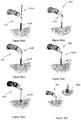
Figure 15 illustrates one technique for dilating tissue with the devices.Figure 15(a) illustrates how the outer cannula is positioned above the incision.Figure 15(b) illustrates how the cannulas is placed into the guide tube such that it rests on skin. -
Figure 15(c) illustrates how the first inner cannula is inserted into the incision. -
Figure 15(d) illustrates how the second inner cannula is then inserted into the incision.Figure 15(e) illustrates how the outer cannula is then inserted into the incision.Figure 15(f) illustrates both inner cannulas then being removed and lowering the guide tube until it sits within the outer cannula. -
Figure 16 illustrate some embodiments of the navigated survival instruments. -
Figure 17 illustrates the array. -
Figure 18 illustrates the verification probe. -
Figure 19 illustrates the patient attachment instruments. -
Figure 20 illustrates tightening bone clamp using clamp driver. -
Figure 21 illustrates the guide post and the quattro spike. -
Figure 22 illustrates one method for inserting a low profile quattro spike into rigid bony anatomy.Figure 22(a) illustrates positioning a quattro spike over a guide post. -
Figure 22(b) illustrates attaching an impaction cap.Figure 22(c) illustrates inserting an assembly into a rigid anatomy.Figure 22(d) illustrates removing a cap and guide pose. -
Figure 23 illustrates inserting a rod attachment instrument including a set screw, to attach to the existing spinal rod. -
Figure 24 illustrates a surveillance marker. -
Figure 25 illustrates a use of a surveillance marker with a bone clamp. -
Figure 26 illustrates a dynamic reference base. -
Figure 27 illustrates a intra-op registration fixture and pivoting arm. -
Figure 28 illustrates a Fluoroscopy Registration Fixture. -
Figure 29 illustrates an end effector motion when moving from one trajectory to the next, wherein 1, 2, and 3 are automatic movements; 4 is manual and optional. -
Figure 30 illustrates a power button, line power indicator and battery indicator. -
Figure 31 illustrates a camera stand undocking.Figure 31(a) illustrates pulling up on the release handle located on a camera stand.Figure 31(b) illustrates clearing the legs of a camera stand legs automatically releasing and moving outward. -
Figure 32 illustrates the connection of a camera to a connector panel on a base station. -
Figure 33 illustrates a camera positioning. -
Figure 34 illustrates pressing a laser button to align the camera. -
Figure 35 illustrates a system with a sterile drape. -
Figure 36 illustrates a foot pedal cable connection. -
Figure 37 illustrates buttons which are illuminated when stabilizers engage and stabilizers disengage. -
Figure 38 illustrates the robotic arm interface plate for connection to the end effector. -
Figure 39 illustrates opening brackets on an end effector and place the end effector on the interface plate by aligning the V grooves and alignment spheres. -
Figure 40 illustrates squeezing brackets on both sides of an end effector and press the handle down to lock into place. -
Figure 41 illustrates a correct and incorrect positioning of a handle down to lock into place. -
Figure 42 illustrates a removal of the end effector. -
Figure 43 illustrates inserting an instrument shaft into an array sleeve. -
Figure 44 illustrates a surgical instrument assembly. -
Figure 45 illustrates attaching a quick connect handle on the proximal end of a shaft of the surgical instrument assembly. -
Figure 46 illustrates attaching a reflective marker to one of a plurality of marker posts of the instrument assembly.Figure 46(a) illustrates lowering the reflective marker onto a marker post.Figure 46(b) illustrates a marker fully seated on the post. -
Figure 47 illustrates a login screen displayed on a monitor. -
Figure 48 illustrates a case management screen displayed on a monitor. -
Figure 49 illustrates a CONFIGURE tab used to display procedure types. -
Figure 50 illustrates a PREPLAN tab displayed on the monitor to select the implant system, desired vertebral level and orientation. -
Figure 51 illustrates a VERIFY tab displaying navigation details including visibility, location and verification status of the instruments selected on the PREPLAN tab. -
Figure 52 illustrates a pop-up screen appearing on the VERIFY tab to indicate the verification progress. -
Figure 53 illustrates verification divots located on the end effector. -
Figure 54 illustrates a green circle indicating a successful verification. -
Figure 55 illustrates a red crossed circle indicating a failed verification. -
Figure 56 illustrates securing a Dynamic Reference Base to a patient attachment instrument. -
Figure 57 illustrates using a clamp driver to a Dynamic Reference Base. -
Figure 58 illustrates the placement of a Dynamic Reference Base and a surveillance marker. -
Figure 59 illustrates a quattro spike. -
Figure 60 illustrates a quattro spike removal tool. -
Figure 61 illustrates removing a quattro spike with a removal tool. -
Figure 62 illustrates attaching a registration fixture to a pivoting arm. -
Figure 63 illustrates a registration fixture connecting to a patient attachment instrument. -
Figure 64 illustrates a registered fiducial. -
Figure 65 illustrates a PLAN tab allowing a user to plan all screw trajectories on a patient image. -
Figure 66 illustrates a NAVIGATE tab allowing a user to visualize a navigated instrument trajectory and a planned trajectory with respect to patient anatomy. -
Figure 67 illustrates a PLAN tab allowing a user to plan all screw trajectories on a patient image. -
Figure 68 illustrates the first screen highlighting the three steps to complete before the fluoroscopy images can be taken to register the pre-operative CT image. -
Figure 69 illustrates a Fluoroscopy Registration Fixture attached to image intensifier. -
Figure 70 illustrates a lateral image within the NAVIGATE tab. -
Figure 71 illustrates selecting the desired level. -
Figure 72 illustrates a successful registration with a check mark being shown next to the active level. -
Figure 73 illustrates how the real-time instrument/implant trajectory is displayed on the patient images along with the planned screw, allowing the user to confirm the desired trajectory. -
Figure 74 illustrates a lateral image within the NAVIGATE tab. -
Figure 75 illustrates the PLAN tab allowing the user to plan all screw trajectories on the patient image. -
Figure 76 illustrates the NAVIGATE tab allowing the user to visualize the navigated instrument trajectory and the planned trajectory with respect to patient anatomy. -
Figure 77 illustrates how the robotic computer system may be used for navigation without the robotic arm and end effector. -
Figure 78 illustrates how the robotic computer system may be used for trajectory guidance using the robotic arm without navigated instruments. -
Figure 79 illustrates a block diagram of electronic components of a robot portion of a robot surgical platform which is configured according to embodiments. -
Figure 80 illustrates a block diagram of a surgical system that includes a surgical implant planning computer which may be separate from and operationally connected to the robot or incorporated therein. -
Figures 81-87 are flowcharts of operations that may be performed by a surgical implant planning computer which is configured according to embodiments. - The following discussion is presented to enable a person skilled in the art to make and use embodiments of the present disclosure. Various modifications to the illustrated embodiments will be readily apparent to those skilled in the art, and the principles herein can be applied to other embodiments and applications without departing from embodiments of the present disclosure. Thus, the embodiments are not intended to be limited to embodiments shown, but are to be accorded the widest scope consistent with the principles and features disclosed herein. The following detailed description is to be read with reference to the figures, in which like elements in different figures have like reference numerals. The figures, which are not necessarily to scale, depict selected embodiments and are not intended to limit the scope of the embodiments. Skilled artisans will recognize the examples provided herein have many useful alternatives and fall within the scope of the embodiments.
- The robotic computer system enables real-time surgical navigation using radiological patient images and guides the trajectory of specialized surgical instruments along a surgeon-specified path using a robotic arm. The system software reformats patient-specific CT images acquired before surgery, or fluoroscopic images acquired during surgery, and displays them on screen from a variety of views. Prior to operating, the surgeon may then create, store, access, and simulate trajectories. During surgery, the system guides the instruments to follow the trajectory specified by the user, and tracks the position of surgical instruments in or on the patient anatomy and continuously updates the instrument position on these images. The surgery is performed by the surgeon, using the specialized surgical instruments.
- The software can also show how the actual position and path during surgery relate to the pre-surgical plan, and can help guide the surgeon along the planned trajectory. While the surgeon's judgment remains the ultimate authority, real-time positional and trajectory information obtained through the robotic computer system can serve to validate this judgment. An example robotic computer system that could be used with embodiments herein is the ExceIsiusGPS™ by Globus Medical.
- The robotic computer system is a Robotic Positioning System that includes a computer controlled robotic arm, hardware, and software that enables real time surgical navigation and robotic guidance using radiological patient images (pre-operative CT, intra-operative CT and fluoroscopy), using a dynamic reference base and positioning camera. The navigation and guidance system determines the registration or mapping between the virtual patient (points on the patient images) and the physical patient (corresponding points on the patient's anatomy). Once this registration is created, the software displays the relative position of a tracked instrument, including the end-effector of the robotic arm, on the patient images. This visualization can help guide the surgeon's planning and approach. As an aid to visualization, the surgeon can plan implant placement on the patient images prior to surgery. The information of the plan coupled with the registration provides the necessary information to provide visual assistance to the surgeon during free hand navigation or during automatic robotic alignment of the end-effector.
- During surgery, the system tracks the position of GPS compatible instruments, including the end-effector of the robotic arm, in or on the patient anatomy and continuously updates the instrument position on patient images utilizing optical tracking. Standard non-navigated metallic instruments that fit through the guide tube at the selected trajectory may be used without navigation while the guide tube is stationary, for uses such as bone preparation (e.g. rongeurs, reamers etc.) or placing MIS implants (e.g. rod inserters, locking cap drivers) that are not related to screw placement. Navigation can also be performed without guidance. System software is responsible for all motion control functions, navigation functions, data storage, network connectivity, user management, case management, and safety functions. robotic computer system surgical instruments are non-sterile, re-usable instruments that can be operated manually or with the use of the positioning system.
- Robotic computer system instruments include registration instruments, patient reference instruments, surgical instruments, and end-effectors. Registration instruments incorporate arrays of reflective markers, and are used to track patient anatomy and surgical instruments and implants; components include the verification probe, surveillance marker, surgical instrument arrays, intra-op CT registration fixture, fluoroscopy registration fixture, and dynamic reference base (DRB). Patient reference instruments are either clamped or driven into any appropriate rigid anatomy that is considered safe and provides a point of rigid fixation for the DRB. Surgical instruments are used to prepare the implant site or implant the device, and include awls, drills, drivers, taps, and probes. End-effectors can be wirelessly powered guide tubes that attach to the distal end of the robotic arm and provide a rigid structure for insertion of surgical instruments.
- The robotic computer system is intended for use as an aid for precisely locating anatomical structures and for the spatial positioning and orientation of instrument holders or tool guides to be used by surgeons for navigating or guiding standard surgical instruments in open or percutaneous procedures. The system is indicated for any medical condition in which the use of stereotactic surgery may be appropriate, and where reference to a rigid anatomical structure, such as the skull, a long bone, or vertebra can be identified relative to a CT-based model, fluoroscopy images, or digitized landmarks of the anatomy.
- Medical conditions which contraindicate the use of the robotic computer system and its associated applications include any medical conditions which may contraindicate the medical procedure itself.
- The robotic computer system has built-in precautions to support navigation integrity but additional steps should be taken to verify the accuracy of the system during navigation. Specific steps include:
- Ensure the stabilizers have been engaged prior to using the robotic arm.
- Do not move the dynamic reference base after successful registration.
- Use a surveillance marker with every procedure to further confirm the accuracy of the images in relation to real- time patient anatomy.
- If a surveillance marker alerts movement of patient relative to the dynamic reference base, perform a landmark check. If a landmark check fails, re-register the patient.
- Use a verified navigation instrument to perform an anatomical landmark check prior to a procedure. If a landmark check fails, re-register the patient.
- This product conforms to the requirements of council directive 93/42/EEC concerning medical devices, when it bears the CE Mark of Conformity shown below, shown at right.
- This product conforms to the requirements of standards listed below when it bears the following NRTL Certification Compliance Mark, shown at right.
- Electric and electromagnetic testing have been performed in accordance with the following applicable standards: ANSI/AAMI ES60601-1, CSA C22.2#60601-1, CISPR 11, IEC 60601-1 (including all national deviations), IEC 60601-1-2, IEC 60601-1-6, IEC 60601-1-9, IEC 60601-2-49 (only portions of this standard are used to demonstrate compliance and proper operation of the robotic computer system when used with high frequency surgical equipment such as a cauterizer), IEC 60825-1, IEC 62304, IEC 62366.
- Based on the robotic computer system floating applied part (type BF) and the safety testing performed, the system is compatible with the use of HF surgical equipment with no restrictions on the conditions of use.
- In accordance with IEC 60601-1-2:2014
Edition - The robotic computer system has an optional 802.11 g/b/n wireless router and tablet option. When installed, this transmits RF power at 2.4 GHz (2.412-2.484 GHz) using DSSS or OFDM with DQPSK or QAM modulation. Maximum RF transmit power is 100 mW.
-
Rated maximum output power of transmitter (W) Separation distance according to frequency of transmitter (m) 150 kHz to 80 MHz 80 MHz to 800 MHz 800 MHz to 2.5GHz 


0.01 0.3* 0.3* 0.3* 0.1 0.37 0.37 0.74 1 1.17 1.17 2.33 10 3.69 3.69 7.38 100 11.67 11.67 23.33 *30 cm is the minimum recommended separation distance even though the calculation would yield a shorter distance. For transmitters rated at a maximum output power not listed above, the recommended separation distance in meters (m) can be estimated using the equation applicable to the frequency of the transmitter, where P is the maximum output power rating of the transmitter in watts (W) according to the transmitter manufacturer. NOTE 1: At 80 MHz and 800 MHz, the separation distance for the higher frequency range applies. NOTE 2: These guidelines may not apply in all situations. Electromagnetic propagation is affected by absorption and reflection from structures, objects and people. - The robotic computer system adheres to industry best practices and FDA guidance on cybersecurity in medical devices. This includes firewall protection and additional protection against virus, malware, data corruption, and unauthorized system access.
- The robotic computer system consists of four main components: Robotic Base Station (shown below), Camera Stand (shown below), Instruments, and System Software.
Figure 1 illustrates a robotic system that includes a robotic base station and a camera stand. - The Robotic Base Station is the main control center for the robotic computer system and includes the components shown below.
Figure 2 illustrates components of the robotic base station. The robotic base station includes avertical column 206 that supports anupper arm 200 connected to alower arm 202, with a bracelet andend effector 204 connected to thelower arm 202. Aninformation ring 220 on thevertical column 206 is illuminated to provide information as described below. Amonitor 218 is connected to thevertical column 206. The robotic base station also includes atablet compartment 216, acontrol panel 208, aconnector panel 210,stabilizers 212, and rollingcasters 214. - The monitor allows the surgeon to plan the surgery and visualize anatomical structures, instruments, and implants in real time. It is a high resolution, flat panel touch screen liquid crystal display (LCD) located on the vertical column. The monitor can be adjusted to the desired location with two hands. An external mouse is available for optional use with the monitor. The mouse is not intended for use within the sterile field.
Figure 3 illustrates the monitor of the robotic base station. - An optional wireless tablet is available for use as a second touchscreen monitor for operative planning and software control. The main monitor remains active at all times during use. The user can lockout tablet use if desired. The tablet compartment is used to store the tablet. The tablet is not intended for use within the sterile field.
-
Button Function To Use Emergency Stop Removes power from motors and applies brake Press down to activate. To deactivate and re-power, twist knob counterclockwise. Line Power Indicator Illuminates when system is plugged into AC power outlet Press to turn ON/OFF Power Button Powers the Robotic Base Station ON/OFF. Illuminated when ON. Press to turn ON/OFF Battery Indicator Indicates level and state of charge All bars are illuminated when fully charged When operating on battery, number of illuminated bars indicates percent of charge Bars progressively illuminate when charging Stabilizers Disengage Illuminates when system is free to move Press to disengage the stabilizers to allow movement of the system Stabilizers Engage Illuminates when system is secured to floor Press to engage the stabilizers, to lock the system in place Left Position Moves upper arm forward and lower arm at a 90º angle to the left Press and hold button. Operator may release button prior to final position and arm will stop in current position. Right Position Moves upper arm forward and lower arm at a 90º angle to the right. Straight Position Moves upper and lower arm forward Stop in current position Dock Position Moves upper and lower arm to rest over the cabinet Vertical Column Up Moves vertical column up Press and hold button. Operator should release button once the desired height is reached. Vertical Column Down Moves vertical column down - The control panel is located at the rear of the Robotic Base Station. This panel is used to display and control system power and general positioning functions.
Figure 4 illustrates the control panel on the rear of the Robotic Base Station and the control panel functions. The control panel includes:emergency stop button 400, stabilizers disengagebutton 402, aleft position button 404, astraight position button 406, aright position button 408, a vertical column upbutton 410, a vertical column downbutton 412, adock position button 414, a stabilizers engagebutton 416, abattery status indicator 418, apower button 420, and aline power indicator 422. - The connector panel is located at the rear of the Robotic Base Station. This panel contains external connection ports for various devices.
Figure 5 illustrates the connector panel located at the rear of the Robotic Base Station. The connector panel includes: anequipotential terminal 562, afoot pedal connector 563, acamera connector port 564, anHDMI connector 565, anethernet connector 566, and dual USB 3.0ports 567. -
Item Function Equipotential Terminal Used to connect to other auxiliary equipment; used by service personnel Foot Pedal Connector Connects to the foot pedal cable Camera Connector Connects to the camera stand cable HDMI Connector Connects to an external monitor Ethernet Connector Connects to a network or intra-operative imaging system for image transfer USB Port 3.0 Connects to a USB device for image transfer Connects to C-Arm via video capture supplied with the Fluoroscopy Registration Fixture - The system consists of four casters with integrated stabilizers. The stabilizers are used to immobilize the system to ensure that it does not move during use.
- The robotic arm, which consists of an upper and lower arm, is attached to the vertical column of the robotic computer system Robotic Base Station. This configuration allows for a wide range of motion.
- The robotic computer system employs a state of the art drive control system along with high performance servo drives to accurately position and control the 5-axis robotic arm in an operating room environment.
Figure 6 illustrates the 5-axis robotic arm. The 5 axes of motion are identified below.Axis Travel Distance Vertical 670 ≥ 480mm Shoulder 672 -150° to 180° Elbow 674 -150° to 150° Roll 676 -135° to 135° Pitch 678 -70° to 70° - The bracelet is located at the distal end of the lower arm. It is a load sensing component that allows user guided positioning of the robotic arm.
- To initiate motion, squeeze the bracelet ring with the thumb and forefinger on opposite sides. While squeezed, apply light force toward the desired direction of motion. The robotic arm will move in the desired direction. The arm moves manually in any direction or along a trajectory if a screw plan is active.
Figure 7 illustrates the lower arm which includes abracelet 700 and abracelet ring 722. - The information ring is located on the upper part of the vertical column. The information ring indicates the status of the robotic computer system. The information ring light blinks while the system is booting up; a solid green light is displayed when the system is ready. Individual colors are used to indicate status, as shown in the table below.
Figure 8 illustrates the upper part of the vertical column in which includes aninformation ring 800 that is limited to provide information indications to a user. -
Color Description Red System is in an error state. Stop all tasks and resolve the issue immediately as it is either a safety issue or a serious problem with the system. Yellow System is in a state in which user intervention is required before a planned trajectory can be activated. Green System is ready. - The camera stand is mobile and adjusts in order to position the camera to view the operating field and optical markers.
Figure 9 illustrates the camera stand. The camera stand includes: acamera 904; a cameralaser alignment light 906; apositioning handle 908; asupport arm 910; aheight adjustment handle 912; alocking handle 914; adocking handle 916; arelease handle 918; acable holder 920;legs 922; andcasters 924.Figure 10 illustrates the rear view of the camera stand showing alignment buttons. The camera stand further includes ahandle tilt button 1020 and alaser button 1022. -
Item Function Camera Used to detect the reflective markers and is attached to the top of the camera stand. For more information, please refer to the NDI Passive Polaris Spectra User Guide. Positioning Handle Used to adjust the camera position to ensure the surgical field is in view. Handle Tilt Button Used to adjust the angle of the positioning handle with respect to the camera in the field of view. Laser Button Turns the camera laser alignment light on and off. The laser light is used for assistance in aligning the camera in the field of view. Arm Provides a large range of positions for the camera. Height Adjustment Handle Allows for adjustment of camera height. Locking Handle Used to lock camera position. Docking Handle Used to collapse the legs for docking the camera stand into the Robotic Base Station. Release Handle Releases the camera from the Robotic Base Station. Casters The camera stand contains four casters. The rear casters are lockable to prevent the camera stand from moving. Legs The camera stand legs swing inward for docking and outward when deployed. Cable Holder Provides storage for the camera stand cable. - The following cable characteristics are required for connecting to external devices: HDMI - Connecting to an external HDMI Monitor requires a shielded HDMI-Male to HDMI-Male cable.
- Network - Connecting to a Hospital network can be done with an unshielded CAT-5e Ethernet cable.
-
FIG. 79 illustrates a block diagram of electronic components of arobot 500 portion of a robot surgical platform which is configured according to embodiments. Therobot 500 can includeplatform subsystem 502,computer subsystem 520,motion control subsystem 540, andtracking subsystem 530.Platform subsystem 502 can includebattery 506,power distribution module 504,platform network interface 512, andtablet charging station 510.Computer subsystem 520 can includecomputer 522,display 524, andspeaker 526.Motion control subsystem 540 can includedriver circuit 542,motors stabilizers effector 544, and controller 546 (e.g., one or more processors and associated circuitry).Tracking subsystem 530 can includeposition sensor 532 andcamera converter 534 which is connectable to amarker tracking camera 570, e.g., via theplatform network interface 512.Robot 500 can include afoot pedal 580 andtablet computer 590. - Input power is supplied to
robot 500 via apower source 560 which may be provided topower distribution module 504.Power distribution module 504 receives input power and is configured to generate different power supply voltages that are provided to other modules, components, and subsystems ofrobot 500.Power distribution module 504 may be configured to provide different voltage supplies toplatform network interface 512, which may be provided to other components such ascomputer 520,display 524,speaker 526,driver 542 to, for example,power motors effector 544,ring 514,camera converter 534, and other components forrobot 500 for example, fans for cooling the various electrical components. -
Power distribution module 504 may also provide power to other components such astablet charging station 510 that may be located within a tablet drawer.Tablet charging station 510 may be configured to communicate through a wired and/or wireless interface withtablet 590.Tablet 590 may be used to display images and other information for use by surgeons and other users consistent with various embodiments disclosed herein. -
Power distribution module 504 may also be connected tobattery 506, which serves as a temporary power source in the event thatpower distribution module 504 does not receive power frominput power 560. At other times,power distribution module 504 may serve to chargebattery 506 when needed. - Other components of
platform subsystem 502 can includeconnector panel 508,control panel 516, andring 514.Connector panel 508 may serve to connect different devices and components torobot 500 and/or associated components and modules.Connector panel 508 may contain one or more ports that receive lines or connections from different components. For example,connector panel 508 may have a ground terminal port that may groundrobot 500 to other equipment, a port to connectfoot pedal 580 torobot 500, and/or a port to connect to trackingsubsystem 530. Thetracking subsystem 530 can include aposition sensor 532,camera converter 534, and themarker tracking camera 570 which may be supported by a camera stand.Connector panel 516 can include other ports to allow USB, Ethernet, HDMI communications to other components, such ascomputer 520. -
Control panel 516 may provide various buttons or indicators that control operation ofrobot 500 and/or provideinformation regarding robot 500. For example,control panel 516 may include buttons to power on or offrobot 500, lift or lower stabilizers 555-558 that may be designed to engage casters to lockrobot 500 from physically moving and/or to raise and lower the robot base and/or a vertical support for the robot arm. Other buttons may controlrobot 500 to stop movement of a robot arm in the event of an emergency, which may remove all motor power and apply mechanical and/or electromechanical brakes to stop all motion from occurring.Control panel 516 may also have indicators notifying the user of certain system conditions such as a line power indicator or status of charge forbattery 506. -
Ring 514 may be a visual indicator to notify the user ofrobot 500 of different modes thatrobot 500 is operating under and certain warnings to the user. -
Computer 522 of thecomputer subsystem 520 includes at least one processor circuit (also referred to as a processor for brevity) and at least one memory circuit (also referred to as a memory for brevity) containing computer readable program code. The processor may include one or more data processing circuits, such as a general purpose and/or special purpose processor, e.g., microprocessor and/or digital signal processor. The processor is configured to execute the computer readable program code in the memory circuit to perform operations, which may include some or all of the operations described herein as being performed by a surgical robot and may further perform some or all of the operations described herein as being performed by a surgical implant planning computer. - The program code includes an operating system and software to operate
robot 500.Computer 522 may receive and process information from other components (for example,tracking subsystem 530,platform subsystem 502, and/or motion control subsystem 540) in order to display information to the user. Further,computer subsystem 520 may includespeaker 526 to provide audio notifications from thecomputer 522 to the user. -
Tracking subsystem 530 can includeposition sensor 532 andcamera converter 534. Theposition sensor 532 may include themarker tracking camera 570.Tracking subsystem 530 may track the location of markers that are located on the different components ofrobot 500 and/or instruments used by a user during a surgical procedure. This tracking may be conducted in a manner consistent with the present disclosure which can include the use of infrared technology that illuminates and enables tracking by thecamera 570 of the location of active or passive elements, such as LEDs or reflective markers, respectively. The location, orientation, and position of structures having these types of markers may be provided tocomputer 522 which may be shown to a user ondisplay 524 and/ortablet 590. For example, a surgical instrument or other tool having these types of markers and tracked in this manner (which may be referred to as a navigational space) may be shown to a user in relation to a three dimensional image of a patient's anatomical structure, such as a CT image scan, fluoroscopic image, and/or other medical image. - The
robot 500 can include a robot base that is coupled to a robot arm which is movable by the motors, e.g., one or more of motors 550-554, relative to the robot base. The robot arm can include an upper arm connected to a vertical support and a lower arm that is rotatably coupled to an end of the upper arm and extends to couple to the end-effector 544.Motion control subsystem 540 may be configured to physically move a vertical column of therobot 500, e.g., raise and lower the robot arm and/or the robot base in a vertical direction, move an upper arm of therobot 500, move a lower arm of therobot 500, and/or rotate the end-effector 544. The physical movement may be conducted through the use of one or more motors 550-554. For example,motor 550 may be configured to vertically lift or lower the robot base and/or the robot arm in a vertical direction.Motor 551 may be configured to laterally move an upper arm around a point of engagement.Motor 552 may be configured to laterally move a lower arm around a point of engagement with the upper arm.Motors effector 544 in a manner that controls the roll and/or tilt, thereby providing multiple angles that end-effector 544 may be moved. These movements may be performed bycontroller 546 responsive to commands from thecomputer 522 and which may control these movements through load cells disposed on the end-effector 544 and activated by a user engaging these load cells to move the end-effector 544 in a desired manner. - The
robot 500 may augment manual input by a user, e.g., when a user applies force to one or more load cells on the end-effector 544, and/or provide automatic movement of the robot arm. Therobot 500 may also augment manual movement by a user and/or provide automatic movement of a vertical column of the robot base. For automatic movement, thecomputer 522 may respond to receiving input from a user, such as by indicating on display 524 (which may be a touchscreen input device) the location of a surgical instrument or component on a three dimensional medical image of the patient's anatomy ondisplay 524. Thecomputer 522 can control one or more of the motors 550-554 to perform automatic movement of the robot arm along a trajectory that has been computed to move theend effector 544 based on location of the user's input relative to the medical image. The user may initiate automatic movement by stepping onfoot pedal 580 and/or by manipulation of another user interface. - The end-effector is the interface between the robotic arm and the system specific surgical instruments. It allows for a rigid connection through the sterile drape to provide precise positioning of instruments placed within its guide tube. The end-effector is provided as a separate component and is sterilized by the user prior to use.
Figure 11 illustrates the isometric and top view of the end-effector 1122 including aguide tube 1122. - The end-effector is powered wirelessly from the robotic arm. This power is used to drive the active markers that are used by the camera to identify the location and orientation of the end-effector. The blue indicator LED illuminates when the end-effector is powered.
- Two end-effectors are available to interface with various surgical instruments. They differ only in the diameter of the guide tube; the active markers have the same geometries. The end-effectors are etched with the guide tube diameter and are color-coded to help ensure that the corresponding size instruments are used.
- The 15mm end-effector is used with all navigated instruments except REVOLVE® instruments, and the 17mm end-effector is used with REVOLVE® instruments. Non-navigated Globus instruments may be used with either end-effector; they are not sized to the guide tube, but must fit within the inner diameter
- Located within the guide tube of the end-effector is an instrument sensing ring. A detector circuit is embedded within the sensing ring that detects when a metal instrument is inserted through the guide tube and disables the active markers and prevents movement of the robotic arm. The visible LED on the end-effector does not illuminate when a metallic instrument is inserted, indicating that an instrument is detected and the active IR emitters are disabled. Disabling the IR emitters prevents the robotic arm from moving. Non-metallic instruments are not identified by the sensing ring and may not be used in the guide tube.
- Size 15mm end-effectors have a detent mechanism on the inside of the tube which interfaces with grooves on the array sleeves to resist array rotation. This aids in holding the tracking array oriented toward the camera while the operator rotates the instrument.
Figure 12 illustrates the detent mechanism 120 on the instrument sensing ring. - A specialized scalpel can be used to create a skin mark at the planned trajectory. Attach a standard scalpel blade to the handle.
- Position the guide tube on the end-effector to the planned trajectory. Adjust the end-effector up or down along the trajectory to allow the scalpel to be viewed. Ensure that scalpel tip can be viewed before making the skin mark.
- Note: The scalpel has a metal core within the radiolucent PEEK material and is detected while in the
guide tube 1122.Figure 13 illustrates ascalpel 100 used through theguide tube 1122. - Cannulas, or dilators, can be used for performing minimally invasive or other techniques that require sequential tissue dilation. The cannulas should only be used under trajectory guidance. Note: The terms "cannula" and "dilator" are used interchangeably.
- Prior to performing sequential tissue dilation, a
scalpel 100 may be used through the guide tube to create a skin mark at the desired trajectory. Move the guide tube away from the trajectory using the bracelet, and create an incision with a scalpel. Refer to the Scalpel section of this manual for instructions. - Once the
guide tube 1122 is at the desired trajectory, position the outer cannula under theguide tube 1122 and above the incision, along the same trajectory. Insert the two inner cannulas into the guide tube and through the outer cannula, and rest on the skin. To sequentially dilate the tissue, slowly insert the first (smallest) cannula into the incision using a cannula pusher. Then advance the second cannula in the same manner. Complete tissue dilation by slowly advancing the outer cannula over the inner cannula. Remove the inner cannula. Lower theguide tube 1122 until it sits just within the outer cannula. Perform surgery through theguide tube 1122 and outer cannula.Figure 14 illustrates the trajectory of the outer cannula. Referring toFigure 14 , a firstinner cannula 1400 is slid into a secondinner cannula 1402 alongtrajectory 1404 into theouter cannula 1406 which is placed within theincision 1408.Figure 15 illustrates one technique for dilating tissue with the devices.Figure 15a illustrates how theouter cannula 1406 is positioned above the incision.Figure 15b illustrates how the cannulas is placed into theguide tube 1122 such that it rests on skin.Figure 15c illustrates how the firstinner cannula 1400 is inserted into the incision.Figure 15d illustrates how the secondinner cannula 1402 is then inserted into the incision.Figure 15e illustrates how theouter cannula 1406 is then inserted into the incision.Figure 15f illustrates bothinner cannulas Figure 15g illustrates lowering theguide tube 1122 until it sits within the outer cannula. - The navigated surgical instruments for use with robotic computer system include drills, awls, probes, taps, and drivers, which may be used to insert Globus screws. These instruments can be used with arrays if navigation is desired, or without arrays if navigation is not used. Each instrument and corresponding array must be assembled prior to use. Instruments are identified by a unique array pattern that is recognized by the camera.
- Navigated instruments are available for each Globus implant system. Refer to the specific system instrument brochures for more information.
Figure 16 illustrate some embodiments of the navigated instruments. The instruments include anawl 1600, aprobe 1602, adrill 1604, atap 1606, and adriver 1608. - Arrays have 4 posts for attaching reflective markers and are available for use with the surgical instruments. The navigated surgical instruments are assembled to a corresponding instrument array, designed with a unique marker pattern which identifies the instrument type. The array is etched with the specific instrument type, e.g. "AWL", "PROBE", "DRILL", "TAP", "DRIVER". Each instrument array has a verification divot, used for instrument verification.
- The verification probe has a built-in array with posts for the reflective markers and is used to verify each instrument before use.
- Arrays used with instruments for the standard 15mm end-effector are identified by a black sleeve. Arrays used with instruments for the 17mm end-effector are identified by a tan sleeve.
Figure 17 illustrates thearray 1700 with arelease button 1702, ahandgrip 1704, amarker post 1706, anarray sleeve 1708, andarray support 1710.Figure 17 also illustrates averification divot 1712 between thearray 1700 and thehandgrip 1704.Figure 18 illustrates theverification probe 200. - Patient attachment instruments are secured to the patient's rigid anatomy, depending on the specific surgical procedure or preference, and are available in various configurations. These instruments may be secured to a variety of anatomical sites. The rod attachment instrument is designed to attach to an existing spinal rod.
- Patient attachment instruments must be safely and rigidly secured to the patient to achieve navigation and guidance accuracy. Verify secure attachment by applying a light force to the distal end of the attachment instrument in all directions. If secure attachment is not maintained during the procedure, the surveillance marker will demonstrate excessive movement; if this occurs, reposition the patient attachment instrument and re-register the patient to the patient images.
- Refer to the specific procedure in the Application section for recommended anatomical locations.
Figure 19 illustrates thepatient attachment instruments 190, which include abone clamp 1900 with surveillance marker, aquattro spike 1902, a lowprofile quattro spike 1904, and arod attachment 1906. - Bone clamps are clamped onto anatomical structures such as the spinous process, iliac crest, long bone, or any rigid bony structure that can be safely clamped.
- The bone clamp is placed onto rigid bony anatomy. The clamp driver is used to tighten the bone clamp. To remove, loosen the bone clamp with the clamp driver, attach the removal tool and lift up the bone clamp.
Figure 20 illustrates tightening bone clamp using clamp driver. - Quattro spikes are inserted into rigid bone of the iliac crest or long bone. The quattro spike is inserted into rigid bony anatomy and gently impacted with a mallet.
- The low profile quattro spike is inserted using a guide post and impaction cap. Find the desired anatomy using the guide post. Place the patient attachment instrument over the guide post. Attach the impaction cap (for low profile quattro spike). Gently impact the assembly with a mallet to insert into bony anatomy. Remove the impaction cap and guide post from the spike.
Figure 21 illustrates theguide post 2100 and thequattro spike 2102.Figure 22 illustrates one method for inserting thequattro spike 2102 into rigid bony anatomy.Figure 22(a) illustrates positioning thequattro spike 2102 over theguide post 2100.Figure 22(b) illustrates attaching theimpaction cap 2103.Figure 22(c) illustrates inserting the assembly into a rigid anatomy.Figure 22(d) illustrates removing thecap 2103 and guide pose. - The rod attachment instrument is designed to attach to an existing spinal rod (4.5mm to 6.35mm diameter). Position the instrument on the existing spinal rod and tighten the set screw with a driver. Ensure a rigid connection. To remove, loosen the set screw and disengage from the rod.
Figure 23 illustrates therod attachment instrument 2300 including aset screw 2302, which are attached to the existing spinal rod. -
Figure 24 illustrates asurveillance marker 240. The surveillance marker is a single reflective marker used to monitor a shift in the Dynamic Reference Base (DRB). Surveillance markers may be used alone or in conjunction with a bone clamp. - Surveillance markers are directly inserted into the iliac crest or long bone, or may be attached to the spinous process using a bone clamp.
Figure 25 illustrates the use of asurveillance marker 240 with a bone clamp. To use a bone clamp with the marker, attach adisposable surveillance marker 240 onto the tip of the bone clamp. Use the clamp driver to secure the bone clamp. Verify that the bone clamp is rigidly secured. - The Dynamic Reference Base (DRB) and patient attachment instruments are used in the patient registration process.
- The DRB is an array with 4 posts for reflective markers and allows the camera to track the location of the patient. The DRB may be attached to any of the patient attachment instruments, using the knob and compression clamp.
Figure 26 illustrates the dynamic reference base, which includesmarker posts 2600 connected to acompression clamp 2602 operated by aDRB knob 2604. - The intra-op CT registration fixture, consisting of a registration fixture and pivoting arm, allows for any intra- operative CT image to be used with the robotic computer system software application. The pivoting arm and registration fixture are assembled prior to use by matching the starburst gears and snapping the two components together.
- The intra-op registration fixture is placed onto a patient attachment instrument by clamping the compression clamp onto the shaft of the attachment instrument, allowing the fixture to hover over the surgical site. The fiducials are detected automatically in the intra-operative scan and are used to register the patient's anatomy during the scan to the DRB, which is tracked by the camera throughout the procedure. The reflective markers are detected by the camera. Once the registration is transferred to the DRB, the intra-op registration fixture is removed to provide access to the surgical site.
Figure 27 illustrates theintra-op registration fixture 2712 and pivotingarm 2708.Figure 27 further illustrates thecompression clamp 2602, theDRB knob 2604, astarburst connection 2406, a gear tooth joint 2710, and a set of seven fiducials 2714. -
Figure 28 illustrates theFluoroscopy Registration Fixture 280. The Fluoroscopy Registration Fixture allows for any intra-operative fluoroscopic image to be used with the robotic computer system software application. The fluoroscopy fixture is attached to the image intensifier of the fluoroscope using the integrated clamps. The fluoroscope and Fluoroscopy Registration Fixture are draped and the reflective markers are placed on the fixture, outside of the drape. The fixture should be positioned such that the reflective markers are seen by the camera in all intended fluoroscope positions (AP, lateral, etc). - The robotic computer system robotic arm positions the end-effector to guide instruments for screw insertion at the desired trajectory. The surgeon manually performs surgery while the instruments are aligned in the desired trajectory for accurate screw placement. Note: The terms "screw plan", "screw trajectory" and "trajectory" are used interchangeably in this manual.
- Motion of the robotic arm is only allowed with continuous pressing of the bracelet or foot pedal. The arm is manually moved by the user in Wrist mode, or is automatically moved to the selected trajectory in Trajectory mode.
- In Wrist mode, the arm may be moved manually to any position within reach of the arm.
- In Trajectory mode, the arm is automatically moved from the current position to the next screw plan when ready, or may be moved manually along a selected trajectory.
- When moving from one screw plan to the next, the arm moves outwards along the current trajectory to a safe distance (200mm) from the surgical site before moving to the new trajectory and downwards along the current trajectory to the anatomy.
-
Mode Software User Action Automatic Motion Manual Motion Wrist Mode No Plan Selected Press Foot Pedal or n/a User may move arm in the desired direction Squeeze Bracelet Trajectory mode Plan Selected Press Foot Pedal or Arm moves automatically to new screw trajectory After reaching the trajectory, user may move arm along trajectory only Squeeze Bracelet - Automatic motion of the arm occurs when moving the guide tube from the current position (either initially or at a current trajectory) to a new screw plan. Once the end-effector and attached guide tube have moved to a new screw plan, the guide tube is locked onto the trajectory and can be moved up and down along the trajectory.
Figure 29 illustrates theend effector 1120 motion when moving from one trajectory to the next, wherein 1, 2, and 3 are automatic movements; 4 is manual and optional. The illustrated movements include movement up alongpath 2902 from astarting position 2900 to clear the screw and patient, movement along anew trajectory path 2904, movement downward to a safe starting position alongpath 2906, and an optional movement along atrajectory path 2908 that may involve manual movement. - Automatic motion of the robotic arm may be stopped by the user, stopped by the system, or prevented.
- To stop motion at any time, press the Emergency Stop button located on the base station.
- Motion is stopped if the end-
effector 1120 detects a force greater than 50N (11lbs). - Motion is also stopped in Trajectory mode when the DRB or the end-
effector 1120 is not in view of the camera. - Motion is prevented when the sensing ring in the
guide tube 1122 detects a metallic instrument. - When a trajectory is selected, motion of the arm with guide tube is only allowed along the trajectory.
-
Method Emergency Stop button pressed End Effector detects force on arm greater than 50N (11lbs) Dynamic reference base not in view of camera (Trajectory mode only) End Effector not in view of camera (Trajectory mode only) Sensing ring detects a metallic instrument in the guide tube - If the robot arm is not able to reach to a safe starting location due to its current position, an error message is shown. The message states "The arm cannot move back any further along the current end-effector trajectory. Acknowledging this message enables the arm to move to the selected plan trajectory from its current position". The user may choose to move forward with the planned trajectory because the shorter starting position is acceptable. If the shorter starting position is not acceptable, a new trajectory must be used or the base must be repositioned.
- To select a new trajectory, the user clears the selected trajectory and positions the robotic arm using the bracelet to a clear position. The bracelet provides flexibility for the user to move the arm around an obstacle.
- To reposition the base, the stabilizers on the casters are disengaged, the station is moved to the desired location and the stabilizers are reengaged. Registration is unaffected because the patient reference (attachment instruments and DRB) has not moved with respect to the patient.
- The system software is responsible for all motion control functions, navigation functions, data storage, network connectivity, user management, case management, and safety functions.
- The top navigation bar takes the user through individual screens for each step of the procedure.
- The respective tab for each step is highlighted when selected and the corresponding screen displayed. The activities performed under each tab are shown in the table below.
Tab Meaning Configure Surgeon, imaging workflow, and anatomy selection Preplan Implant system selection and desired anatomical location identification Verify Navigated instrument verification Image Loading of patient images used for planning and navigation Plan Estimation of desired implant location with respect to patient images Navigate Screw plan with real-time display of navigated instrument and implant (actual plan) with respect to patient images -
Figure 30 illustrates thepower button 3000,line power indicator 3002 andbattery indicator 3004. Press thePower Button 3000 on the control panel to turn the system on. ThePower Button 3000 is illuminated when the system is on. Undocking and Positioning Camera Stand - To release the camera stand from the Robotic Base Station, unwrap the cord holding the monitor arm and the camera arm together, and pull up on the release handle located on the camera stand. Once the legs of the camera stand have cleared the base station, they will automatically release and move outward.
Figure 31 illustrates the camera stand undocking.Figure 31(a) illustrates pulling up on the release handle located on the camera stand.Figure 31(b) illustrates clearing the legs of the camera stand legs automatically releasing and moving outward. - Unwrap the camera cord from the cord holder and plug into the connector panel on the base station.
- Move the camera to the operating room (O.R.) table and engage the wheel brakes by stepping on the lever located on the wheel.
- Align the camera to view the surgical field.
-
Figure 32 illustrates the connection of the camera to the connector panel on the base station.Figure 33 illustrates the camera positioning. - Press and hold the laser button located on the positioning handle of the camera to activate the camera's alignment laser and adjust the position so the laser points to the center of the surgical field.
Figure 34 illustrates pressing thelaser button 3400 to activate a laser which facilitates user alignment of the camera. - A special surgical drape is designed for the robotic computer system Robotic Base Station. Drape the robotic arm, monitor and front of the base station, by following the instructions detailed in the package insert provided with the sterile drape.
Figure 35 illustrates the system with a sterile drape. - Unwrap the foot pedal from the foot pedal basket and position it on the level ground at a comfortable distance from the operator's feet. The foot pedal is IPX68 rated and is acceptable for use in areas where liquids are likely to be found. Plug the foot pedal cord into the connector panel. The foot pedal allows the arm to move to the active trajectory, similar to the action of the bracelet on the lower arm.
- Position the Robotic Base Station next to the patient at a comfortable distance from the surgeon. Move the robotic arm, using the bracelet, around the planned trajectories to ensure the arm can reach all locations before engaging the stabilizers.
Figure 36 illustrates the foot pedal cable connection. - Press the Stabilizers Engage button on the control panel to lower the stabilizers on the casters. The button is illuminated when the stabilizers are engaged.
Figure 37 illustrates the buttons which are illuminated when the stabilizers engage (e.g. responsive to pressing the stabilizers engage button 3700) and stabilizers disengage (e.g. responsive to pressing the stabilizers disengage 3702). - The
end effector 1120 connects to therobotic arm 380 through theinterface plate 381 over the custom drape. A magnetic assist helps to position and self-align the end effector. - The
end effector 1120 is equipped with a drape-friendly clamp that allows it to be removed and reattached up to 3 times during a procedure without damaging the drape.Figure 38 illustrates therobotic arm 380interface plate 381 for connection to theend effector 1120. -
Figure 39 illustrates opening thebrackets 384 on theend effector 1120 and place theend effector 1120 on the interface plate by aligning the V grooves andalignment spheres 382. -
Figure 40 illustrates squeezing thebrackets 384 on both sides of the end effector and press thehandle 383 down to lock into place. -
Figure 41 illustrates the correct (right image) and incorrect (left image) positioning of thehandle 383 down to lock into place. - To remove the end-effector from the robotic arm, pull up on the
handle 383 to release the spring andside brackets 384.Figure 42 illustrates the removal of theend effector 1120. - To assemble the surgical instruments for navigation, press the release button on the
array sleeve 4301 and insert theinstrument shaft 4302 into the sleeve of the respective instrument array. Slide theshaft 4302 through the sleeve until it clicks into place. Gently pull up on the instrument shaft to confirm it is locked.Figure 43 illustrates inserting theinstrument shaft 4302 into thearray sleeve 4301, and further illustrates arelease button 4300 which releases the array. - Attach a
quick connect handle 4500 on the proximal end of theshaft 4302 when needed. To remove the instrument from the array, push therelease button 4300 located on the middle of the array.Figure 44 illustrates thesurgical instrument assembly 4400.Figure 45 illustrates attaching thequick connect handle 4500 on the proximal end of the shaft of thesurgical instrument assembly 4400. - Attach the disposable reflective markers to each of the marker posts of each instrument assembly. Ensure that the markers are fully seated on the posts.
Figure 46 illustrates attaching areflective marker 4600 to one of a plurality of marker posts of the instrument assembly.Figure 46(a) illustrates lowering thereflective marker 4600 onto a marker post.Figure 46(b) illustrates themarker 4600 fully seated on the post. - To login, type the four-digit pin on the touch screen of the monitor. The four digit pin is provided during system installation and can be changed by contacting Tech Support.
Figure 47 illustrates the login screen displayed on the monitor. - A case encompasses all of the data associated with performing a procedure, including surgeon preferences, medical images, and plans.
- After logging in, the SELECT CASE page is displayed on the monitor.
- To select an existing case, select the corresponding row from the case list. To start a new case, click the new case icon. Click the right arrows to advance to the next tab.
Figure 48 illustrates the case management screen displayed on the monitor. - Spine surgical procedures are supported by the robotic computer system.
Figure 49 illustrates the CONFIGURE tab used to display procedure types. - Spinal surgical applications supported by the robotic computer system system are listed below.
-
Procedures Patient Position Posterior Cervical Prone Posterior Thoracic Prone Anterolateral Thoracic Lateral Posterior Lumbar Prone Lateral Lumbar Lateral - Globus spinal implant systems that are compatible with the robotic computer system are listed below.
-
CREO® Stabilization System REVERE® Stabilization System REVOLVE® Stabilization System ELLIPSE® Occipito-Cervico-Thoracic Spinal System QUARTEX® Occipito-Cervico-Thoracic Spinal System SI-LOK® Sacroiliac Joint Fusion System - After selecting a case, the CONFIGURE tab is displayed on the monitor.
- Using the CONFIGURE tab, select the surgeon, the imaging modality and the procedure type. Click the right arrows to advance to the next tab.
- Using the PREPLAN tab, select the implant system, desired vertebral level and orientation, and click the desired implant location on the anatomical model. Click the right arrows to advance to the next tab.
Figure 50 illustrates the PREPLAN tab displayed on the monitor to select the implant system, desired vertebral level and orientation. -
Figure 51 illustrates the VERIFY tab displaying navigation details including visibility, location and verification status of the instruments selected on the PREPLAN tab. Verification is used to ensure all instruments are accurate and have not been damaged during handling and sterilization. The operator must assemble all instruments prior to verification (see Surgical Instrument Assembly). - The VERIFY tab shows CAMERA VIEW and INSTRUMENT STATUS.
- CAMERA VIEW is a real-time view from the perspective of the camera with color circles indicating instrument location. A solid colored circle indicates that the instrument is visible by the camera, while a hollow circle indicates that it is not visible. The colored circle grows larger as the instrument is moved closer to the physical camera and smaller as it moves away from the camera. The ideal distance from the camera is approximately 2 meters or 6 feet.
- INSTRUMENT STATUS lists each instrument and its verification status, with corresponding color circles to identify each instrument. The verification status is symbolized by a checkmark if verification is successful and an X-mark if the verification failed. When no icon appears, the instrument is not verified.
- Verify each instrument as follows: place the tip of the instrument to be verified into verification divots located on the end-effector and on any other instrument array for convenience; ensure both instruments are visible and held steady; and use a pop-up screen appearing on the VERIFY tab to indicate the verification progress.
Figure 52 illustrates the pop-up screen appearing on the VERIFY tab to indicate the verification progress.Figure 53 illustrates theverification divot 1712 which between thehand grip 1704 and thearray 1700. - Once verification is complete, verification status is indicated on the screen with the tip error displayed in mm. If verification has failed (red crossed circle), verification must be repeated until it is successful (green circle).
- When all instruments are successfully verified, advance to the next tab.
Figure 54 illustrates thegreen circle 5401 indicating a successful verification.Figure 55 illustrates the red crossedcircle 5402 indicating a failed verification. Patient Attachment Instruments - Patient attachment instruments are secured to rigid bony anatomy neighboring the surgical site. Select the desired instrument. Patient attachment instruments should be placed no more than 185mm from the center of the surgical site to maintain accuracy.
- Bone clamps are clamped onto anatomical structures such as the spinous process, iliac crest, long bone, or any rigid bony structure that can be safely clamped.
- Quattro spikes are inserted into the iliac crest or a long bone.
- Rod attachments are secured to an existing spinal rod, 4.5mm to 6.35mm in diameter.
- Refer to the table below for recommended anatomic locations for the various patient attachment instruments.
-
Spine Procedures Patient Position Patient Attachment Instrument Recommended Patient Attachment Instrument Location Posterior Cervical Prone Bone Clamp Spinous Process C2-T3 Rod Attachment Existing Rod Posterior Thoracic Prone Bone Clamp Spinous Process T1-L1 Rod Attachment Existing Rod Anterolateral Thoracic Lateral Bone Clamp Spinous Process T1-L1 Posterior Lumbar Prone Quattro Spike Iliac Crest Low Profile Quattro Spike Iliac Crest Bone Clamp Spinous Process T12-L5 Rod Attachment Existing Rod Lateral Lumbar Lateral Quattro Spike Iliac Crest Low Profile Quattro Spike Iliac Crest Bone Clamp Spinous Process T12-L5 Rod Attachment Existing Rod - Position the compression clamp on the Dynamic Reference Base (DRB) over the patient attachment instrument and tighten the knob. If needed, the clamp driver can be used to further tighten the knob.
- Position the reflective markers on the DRB in the direction of the camera. Care should be taken with initial placement of the patient reference instrument as to not interfere with the surgical procedure.
- Following navigation, the patient attachment instrument is removed.
Figure 56 illustrates securing a Dynamic Reference Base to a patient attachment instrument.Figure 57 illustrates using a clamp driver to the Dynamic Reference Base. - The surveillance marker is inserted into rigid bony anatomy to track the relative distance to the DRB, to identify unwanted shifts in the DRB during the procedure.
- Surveillance markers are inserted into the iliac crest or long bone, or may be attached to the spinous process using a bone clamp. Verify that the clamp is rigidly secured. The surveillance marker should be placed no more than 185mm from the Dynamic Reference Base. Refer to the table below for recommended anatomic locations.
-
Spine Procedures Patient Position Patient Attachment Instrument Recommended Patient Attachment Instrument Location Posterior Cervical Prone Bone Clamp Spinous Process C2-T3 Posterior Thoracic Prone Single Iliac Crest Bone Clamp Spinous Process T1-L1 Anterolateral Thoracic Lateral Bone Clamp Spinous Process T1-L1 Posterior Lumbar Prone Single Iliac Crest Bone Clamp Spinous Process T12-L5 Lateral Lumbar Lateral Single Iliac Crest Bone Clamp Spinous Process T12-L5 - Attach a disposable reflective marker to the marker post of the surveillance marker. Attach the impaction cap, designed to fit over the reflective marker sphere, onto the surveillance marker. Insert the surveillance marker into rigid bony anatomy near the surgical site, and gently impact with a mallet. Remove the impaction cap. Remove the reflective marker prior to using the removal tool.
Figure 58 illustrates the placement of the Dynamic Reference Base (DRB) 5800 and thesurveillance marker 5804. TheDRB 5800 includesreflective markers 5802. - To use a bone clamp with the marker, attach a disposable marker onto the tip of the bone clamp. Use the clamp driver to secure the bone clamp. Verify that the clamp is rigidly secured.
- The quattro spikes and surveillance marker are removed from bony anatomy manually or using the removal tool. The bone clamp is removed by loosening the clamp with the clamp driver, attaching the removal tool and lifting up the bone clamp.
Figure 59 illustrates a quattro spike.Figure 60 illustrates a quattro spike removal tool.Figure 61 illustrates removing a quattro spike with a removal tool. -
Figure 62 illustrates attaching aregistration fixture 6200 to apivoting arm 6202. Place thepivoting arm starburst 6206 over thestarburst 6206 on theregistration fixture 6200 and rotate 90° to secure. Referring to theenlarged view 6208 of thepivoting arm 6202 positioned over thestarburst 6206, push thelock post 6204 from the bottom and rotate the arm 90° until the pin in thelock post 6204 is seated to secure the fixture.Enlarged view 6210 shows thepivoting arm 6202 attached and rotated to become secured to theregistration fixture 6200. -
Figure 63 illustrates aregistration fixture 6200 connecting to a patient attachment instrument. Position thefixture 6200 on the patient attachment instrument post and tighten the compression clamp knob. If needed, the clamp driver can be used to further tighten the knob. - To release the
pivoting arm 6202, push thelock post 6204 on thefixture 6200, rotate the pivoting arm 90° and pull up. - The Intra-op CT Registration Fixture has six degrees of freedom and can be moved by adjusting one of the three joints so that it is stable and hovering over the surgical site. Only the metal fiducials embedded in the fixture need to be in the 3D scan (not the reflective markers). It is important that the Intra-op CT Registration Fixture does not move between the image acquisition and performing an anatomical landmark check.
- The IMAGE tab shows the steps needed to load a CT scan image. The image can be loaded from a USB drive or hard drive. If the image is transferred via the Ethernet, it automatically appears on the hard drive when the transfer is complete.
- To view images on a USB drive, insert the USB drive into the USB port on the connector panel. To load an image, select the hard drive or USB drive icon and select the desired patient image. Click the right arrows to load the patient images and advance to the next tab.
- Automatic registration is performed when loading images.
Figure 64 illustrates a registered fiducial. If this step fails, the manual registration screen will be shown to allow manual registration as described below. - The image on the left panel of the registration screen is a full scan with a depiction of the intra-op CT.
- The registration fixture and the seven fiducials should be visible below the image. Fiducials that are not registered need to be adjusted by the operator. On the screen, select a fiducial that is not registered; that image will appear on the right. Move the blue circle on the screen until it surrounds the white fiducial marker. The three small boxes at the bottom of the right panel show the x, y and z direction of the fiducial and all must be adjusted until the blue circle is centered. Ensure that all seven fiducials are properly identified by viewing the 3D model of the intra-op registration fixture. A fiducial may be deleted by selecting the delete icon on the right panel. Click the right arrows to confirm that the fiducials have been properly identified before proceeding to the next step.
- After registration has been completed, a landmark check should be performed to ensure that the registration was calculated successfully. Using the verification probe, touch an anatomical landmark or a fiducial on the registration fixture and verify that the corresponding location is shown on the system monitor. Repeat this process using 2-3 landmarks.
- Carefully remove the Intra-op CT Registration Fixture. Ensure the patient attachment instrument does not move.
-
Figure 65 illustrates the PLAN tab allowing the user to plan all screw trajectories on the patient image. Screws are preloaded on the right hand side of the screen, based on selections made in the PREPLAN tab. - To add a screw onto the planning page, drag and drop the appropriate screw label on the image at the desired slice.
- The active screw plan is shown in green. Details of the active screw plan are shown on the lower right of the screen, including screw family, diameter, and length. Click on the right arrows to advance to the next tab once plans are complete for all screws.
-
Screw Body Press and move a long screen to translate the screw along the current plane of the anatomy Screw Head Press and move to change the angle of the trajectory, pivoting along the tip of the screw Screw Tip Press and move to change the angle of the trajectory, pivoting along the head of the screw Scroll Bar The scroll baris the dial control located above the head of the screw. Press the scroll bar and moveto rotate the anatomy 360° about the screw. -
Screw Tip Press and move longitudinally to automatically adjust the length of the screwto available screwsizes Screw Diameter Press the screw diameter button located on the right hand side of the screen to select other options available with the selected implant set Screw Length Press the screw length button located on the right hand side of the screen toselect other options available with the selected implant set -
FIG. 80 illustrates a block diagram of asurgical system 600 that includes a surgicalimplant planning computer 610 which may be separate from and operationally connected to therobot 500 or at least partially incorporated therein. Alternatively, at least a portion of operations disclosed herein for the surgicalimplant planning computer 610 may be performed by components of therobot 500 such as by thecomputer subsystem 520. - Referring to
FIG. 80 , the surgicalimplant planning computer 610 includes adisplay 612, at least one processor circuit 614 (also referred to as a processor for brevity), at least one memory circuit 616 (also referred to as a memory for brevity) containing computerreadable program code 618, and at least one network interface 620 (also referred to as a network interface for brevity). Thenetwork interface 620 can be configured to connect to aCT image scanner 630, afluoroscopy image scanner 640, animage database 650 of medical images, components of thesurgical robot 500, themarker tracking camera 570, and/or other electronic equipment. - When the surgical
implant planning computer 610 is at least partially integrated within thesurgical robot 500, thedisplay 612 may correspond to thedisplay 524 and/or thetablet 590, thenetwork interface 620 may correspond to theplatform network interface 512, and theprocessor 614 may correspond to thecomputer 522. - The
processor 614 may include one or more data processing circuits, such as a general purpose and/or special purpose processor, e.g., microprocessor and/or digital signal processor. Theprocessor 614 is configured to execute the computerreadable program code 618 in thememory 616 to perform operations, which may include some or all of the operations described herein as being performed by a surgical implant planning computer.FIGs. 81 through 87 illustrates various operations that can be performed by theprocessor 614 in accordance with some embodiments of the present disclosure. - Referring to
FIGs. 80 and81 , theprocessor 614displays 700 on the display device a CT image of a bone that is received from theCT image scanner 630 through thenetwork interface 620. Theprocessor 614 receives 702 a user's selection of a surgical screw from among a set of defined surgical screws, such as by a user touch selecting user-selectable indicia shown through a touch sensitive screen overlay on thedisplay 612. Theprocessor 614 displays 704 a graphical screw representing the selected surgical screw as an overlay on the CT image of the bone. - The
processor 614controls 706 angular orientation and location of the displayed graphical screw relative to the bone in the CT image responsive to receipt of user inputs, which may be provided by the user touch selecting and/or touch dragging a finger on thedisplay 614 and/or via another user interface, such as a touchpad, joystick, dials, etc. Theprocessor 614stores 708 an indication of the selected surgical screw and an angular orientation and a location of the displayed graphical screw in a surgical plan data structure, e.g., withinmemory 616, responsive to receipt of a defined user input, such as a user selecting a displayed indicia for providing a keyboard input. As will be described in further detail below, theprocessor 614 may control 710 therobot 500 based on the surgical plan data structure to move the robot arm relative to a patient. - The angular orientation and the location that is stored 708 in the surgical plan data structure may be configured to indicate the angular orientation and the location of the displayed graphical screw relative to an angular orientation and a location of the bone in the CT image. The operations to display 704 the graphical screw representing the selected surgical screw as an overlay on the CT image of the bone, can include determining a trajectory along an axis of the graphical screw, and displaying a trajectory line that extends from adjacent to a tip of the graphical screw and along the trajectory to facilitate a user visually orienting and positioning the graphical screw relative to a desired insertion location on the bone.
- The operations to control 706 angular orientation and location of the displayed graphical screw relative to the bone in the CT image responsive to receipt of user inputs, can include translating a location of the displayed graphical screw responsive to determining that the user has pressed on a touch-sensitive screen of the
display device 612 over a screw body of the graphical screw while moving location of the user's continued pressing along the touch-sensitive screen. The operations can further include angularly pivoting the displayed graphical screw responsive to determining that the user has pressed on the touch-sensitive screen over a screw head and/or tip of the graphical screw while moving location of the user's continued pressing along the touch-sensitive screen. - Alternatively or additionally, the operations to control 706 angular orientation and location of the displayed graphical screw relative to the bone in the CT image responsive to receipt of user inputs, can include selecting a length of the displayed graphical screw from among a set of defined lengths for surgical screws responsive to determining that the user has pressed on a touch-sensitive screen of the display device over a screw tip or a screw head of the graphical screw while moving location of the user's continued pressing along the touch-sensitive screen a measured distance. The selected length of the surgical screw is then stored 708 in the surgical plan data structure.
- The operations to control 706 orientation and location of the displayed graphical screw relative to the bone in the CT image responsive to receipt of user inputs, can include modifying a size and/or a rotational angle of the displayed graphical screw on the CT image responsive to tracking motion of a user's hand relative to an input device, such as by tracking motion of the user's finger on a touch sensitive screen overlay on the
display 612, on a touchpad, etc. -
Figure 66 illustrates the NAVIGATE tab allowing the user to visualize the navigated instrument trajectory and the planned trajectory with respect to patient anatomy. - The robotic arm precisely aligns the end-effector to the planned trajectory. Select the desired screw label on the right of the screen. The screw plan is active when the screw label is highlighted and the robotic arm can be moved by the bracelet or pressing the foot pedal. The robotic arm first moves up in order to clear obstacles in the surgical field and then down along the trajectory. Once on the trajectory, the robotic arm can move up/down along the trajectory but does not move off of the trajectory unless the screw plan is deselected.
- The real-time instrument/implant trajectory is displayed on the patient images along with the planned screw, allowing the user to confirm the desired trajectory. If the real-time trajectory is not acceptable, the user can return to the PLAN tab to select another trajectory. If the real-time trajectory is acceptable, the user inserts the screw according to the instrument's current trajectory to the desired depth.
- GPS instruments are displayed as they are advanced through the end-effector. While navigating the instruments, periodically observe the monitor and surgical site to ensure consistency between tactile and navigation feedback. Non-navigated metallic Globus instruments may be used through the guide tube while it is stationary for surgical applications unrelated to screw placement.
- Monitor the surveillance marker during the procedure. If the surveillance marker indicates significant movement of the DRB, perform an anatomical landmark check. If the landmark check is satisfactory, re-register the surveillance marker. If the landmark check fails, re-register the patient.
- There are multiple navigation tab icons. Referring to
Figure 66 , theforce gauge 661 indicates the force exerted on the end-effector. The image of the instrument at the bottom of the force gauge shows the active instrument in the end-effector or the end-effector image if no instrument is inserted. The surveillancemarker error gauge 662 indicates the distance that the patient reference has moved in relation to the surveillance marker. The full range of the scale is 2mm. TheDRB icon 663 indicates dynamic reference base visibility. If the DRB is visible by the camera, the background is green. If the DRB is not visible by the camera, the background is red. - As explained above, the surgical
implant planning computer 610 can control 710 operations of thesurgical robot 500. Referring to the operational embodiment ofFIG. 82 , theprocessor 614 of the surgicalimplant planning computer 610 can control 710 therobot 500 by providing 800 the surgical plan data structure to therobot 500 to control movement of the robot arm relative to the robot base. - Referring to the alternative or additional operations of
FIG. 83 , theprocessor 614 of the surgicalimplant planning computer 610 can control 710 therobot 500 by controlling 900 selected ones of the motors 550-554, either directly or indirectly via thecomputer 522 and/orcontroller 546, responsive to content of the surgical plan data structure to regulate movement of the robot arm while positioning an end-effector 544, which is connected to the robot arm, relative to a patient. Theprocessor 614 can also control 902 angular orientation and location of the displayed graphical screw on thedisplay 612 responsive to the movement of the robot arm while the end-effector 544 is positioned relative to the patient. - In a further embodiment, the
processor 614 can directly or indirectly control 900 one or more of the motors 550-554 to move the end-effector 544 in a direction along a trajectory that is defined by the content of the surgical plan data structure, and can control 902 location of the displayed graphical screw responsive to the movement of the end-effector 544 along the trajectory. - In a further embodiment, while moving the end-
effector 544 along the trajectory, theprocessor 614 can directly or indirectly control one or more of the motors 550-554 to resist movement of the end-effector 544 in a direction that is perpendicular to the trajectory until another operation is perform that cancels an end-effector trajectory constraint mode. In a further embodiment, prior to initiating the end-effector trajectory constraint mode, theprocessor 614 can directly or indirectly control one or more of the motors 550-554 to move the end-effector 544 in a direction upward away from the patient and then toward a location along the trajectory toward the patient, and prevent initiation of the end-effector trajectory constraint mode before reaching the location along the trajectory. The processor can control angular orientation and location of the displayed graphical screw responsive to the movement of the robot arm away from the patient and then toward the location along the trajectory. - The IMAGE tab shows the steps needed to load a CT scan image. The image can be loaded from a USB drive or hard drive. If the image is transferred through the Ethernet, it automatically appears on the hard drive when the transfer is complete.
- To view images on a USB drive, insert the USB drive into the USB port on the connector panel. To load an image, select the hard drive or USB drive icon and select the desired patient image. Click the right arrows to load the patient images and advance to the next tab.
-
Figure 67 illustrates the PLAN tab allowing the user to plan all screw trajectories on the patient image. Screws are preloaded on the right-hand side of the screen, based on selections made in the PREPLAN tab. - To add a screw onto the planning page, drag and drop the appropriate screw label on the image at the desired slice. The active screw plan is shown in green. Details of the active screw plan are shown on the lower right of the screen, including screw family, diameter, and length. Click on the right arrows to advance to the next tab once plans are complete for all screws.
-
Screw Body Press and move along screen to translate the screw along the current plane of the anatomy Screw Head Press and move to change the angle of the trajectory, pivoting along the tip of the screw Screw Tip Press and move to change the angle of the trajectory, pivoting along the head of the screw Scroll Bar The scroll bar is the dial control located above the head of the screw. Press the scroll bar and move to rotate the anatomy 360° about the screw. -
Screw Tip Press and move longitudinally to automatically adjust the length of the screw to available screw sizes Screw Diameter Press the screw diameter button located on the right hand side of the screen to select other options available with the selected implant set Screw Length Press the screw length button located on the right hand side of the screen to select other options available with the selected implant set - Pre-operative CT imaging workflow planning operations that can be performed by the surgical
implant planning computer 610 and, more particularly by theprocessor 614, are now described in the context of the embodiments shown inFIG. 84 . - Referring to
FIG. 84 , the operations can include loading 1000 a CT image of a bone, which is received from theimage database 650 through thenetwork interface 620, into thememory 616. The operations include displaying 1002 the CT image on thedisplay device 612, and receiving 1004 a user's selection of a surgical screw from among a set of defined surgical screws. The operations display 1006 a graphical screw representing the selected surgical screw as an overlay on the CT image of the bone. The operations control 1008 angular orientation and location of the displayed graphical screw relative to the bone in the CT image responsive to receipt of user inputs. The operations store 1012 an indication of the selected surgical screw and an angular orientation and a location of the displayed graphical screw in a surgical plan data structure responsive to user input. The surgical plan data structure is configured for use by therobot 500 to control movement of the robot arm in accordance with various embodiments disclosed herein. - The operations to display 1006 the graphical screw representing the selected surgical screw as an overlay on the CT image of the bone, can include determining a trajectory along an axis of the graphical screw, and displaying 1010 a trajectory line that extends from adjacent to a tip of the graphical screw and along the trajectory to facilitate a user visually orienting and positioning the graphical screw relative to a desired insertion location on the bone.
- The operations to control 1008 angular orientation and location of the displayed graphical screw relative to the bone in the CT image responsive to receipt of user inputs, can include translating a location of the displayed graphical screw responsive to determining that the user has pressed on a touch-sensitive screen of the
display device 612 over a screw body of the graphical screw while moving location of the user's continued pressing along the touch-sensitive screen. The operations can alternatively or additionally include angularly pivoting the displayed graphical screw responsive to determining that the user has pressed on the touch-sensitive screen over a screw head and/or tip of the graphical screw while moving location of the user's continued pressing along the touch-sensitive screen. - The operations to control 1008 angular orientation and location of the displayed graphical screw relative to the bone in the CT image responsive to receipt of user inputs, can include selecting a length of the displayed graphical screw from among a set of defined lengths for surgical screws responsive to determining that the user has pressed on a touch-sensitive screen of the
display device 612 over a screw tip or a screw head of the graphical screw while moving location of the user's continued pressing along the touch-sensitive screen a measured distance. - The selected length of the surgical screw is stored 1012 in the surgical plan data structure.
- The operations can include controlling 1014 angular orientation and location of the displayed graphical screw responsive to the movement of the robot arm while the end-
effector 544 is being positioned relative to a patient. - The NAVIGATE tab allows the user to visualize the navigated instruments and trajectory alignment with respect to patient anatomy, according to the screw plan.
-
Figure 68 illustrates the first screen highlighting the three steps to complete before the fluoroscopy images can be taken to register the pre-operative CT image. Animation visually depicts the steps. -
Figure 69 illustrates a Fluoroscopy Registration Fixture attached to image intensifier. Attach the Fluoroscopy Registration Fixture to the image intensifier on the C-arm by turning the clamps clockwise until tight. Drape the fluoroscope and Fluoroscopy Registration Fixture and attach new reflective markers outside of the drape. Position the fixture such that the reflective markers are facing the camera. Attach the video capture cable (yellow jack) to the C-arm viewing station. Plug the video capture USB cable into either of the two USB ports on the robotic computer system connector panel. - Ensure that the Dynamic Reference Base is visible to the camera after the C-Arm is in place.
- Register the surveillance marker by placing an instrument close to the reflective sphere on the surveillance marker but not touching. The box turns green when it is activated. Click the right arrows to advance to the next tab. Pre-Operative CT Imaging Workflow Navigation Operations
- Pre-operative CT imaging workflow navigation operations that can be performed by the surgical
implant planning computer 610 and, more particularly by theprocessor 614, are now described in the context of the embodiments shown inFIG. 85 . - Referring to
FIG. 85 , the operations can include performing 1100 a registration setup mode that includes determining occurrence of a first condition indicating that amarker tracking camera 570 can observe to track reflective markers that are on a fluoroscopy registration fixture (e.g., connected to the fluoroscopy imager 640), and further determining occurrence of a second condition indicating that themarker tracking camera 570 can observe to track dynamic reference base markers attached to the robot arm and/or an end-effector 544 connected to the robot arm. The operations display 1102 on thedisplay device 612 an indication of when both of the first and second conditions occur, and determine that the registration setup mode is allowed to be marked satisfied when at least both of the first and second conditions are determined to occur. - Acquire the intra-operative fluoroscopic images, one AP and one lateral for each level planned. The same image may be used for multiple levels.
- The following three conditions must be met prior to acquiring the images: (1) the DRB is visible by the camera; (2) the Fluoroscopy Registration Fixture is visible by the camera; and (3) a valid fluoroscopic image was taken.
-
Figure 70 illustrates a lateral image within the NAVIGATE tab. Referring toFigure 70 . Each of the three images on the left of the screen turns green when ready for image capture. When all three conditions are met, acquire the intra-operative fluoroscopic image and then select the CAPTURE button to transfer the image to the system. Once both images are successfully captured, the spinal level on the right side of the screen displays a check mark. Click the right arrows to advance to the next tab. -
Figure 71 illustrates selecting the desired level. To do so, the user drags and drops the planned screw onto the fluoroscopic images. Use the circle control points to roughly position the screw within the vertebral body. Ensure that the screw shank is positioned correctly, the head and tail of the screws are in the desired direction, and left/right are correctly oriented. Click the register button when complete to allow registration. -
Figure 72 illustrates a successful registration with a check mark being shown next to the active level. Click the right arrows when registration is complete. - With further reference to
FIG. 85 , the operations by the surgicalimplant planning computer 610 can further include operating 1104 while both of the first and second conditions are determined 1104 to continue to occur, to allow operations to be performed to obtain a first intra-operative fluoroscopic image of the patient along a first plane and to obtain a second intra-operative fluoroscopic image of the patient along a second plane that is orthogonal to the first plane. The operations determine that a registration mode is allowed to be marked satisfied when the first and second intra-operative fluoroscopic images have been obtained. - With further reference to
FIG. 85 , the operations by the surgicalimplant planning computer 610 can further include displaying 1106 the first and second intra-operative fluoroscopic images on thedisplay device 612. The operations display 1108 the graphical screw as an overlay on both of the first and second intra-operative fluoroscopic images. The operations control 1110 angular orientation and location of the displayed graphical screw relative to a bone in the first and second intra-operative fluoroscopic images responsive to receipt of user inputs. - Operations may alternatively or additionally include determining 1112 when the angular orientation and location of the displayed graphical screw relative to the bone in the first and second intra-operative fluoroscopic images satisfies a registration rule for corresponding to the angular orientation and the location of the displayed graphical screw in the surgical plan data structure, and then responsively displaying on the
display device 612 an indication of when the registration rule is satisfied. - With further reference to
FIG. 85 , the operations by the surgicalimplant planning computer 610 can further include, based on determining that the registration rule is satisfied, controlling 1114 one or more of the motors 550-554 responsive to content of the surgical plan data structure to regulate movement of the robot arm while positioning the end-effector 544 relative to the patient. The operations can further control 1114 angular orientation and location of the graphical screw that is displayed, responsive to the movement of the robot arm while the end-effector 544 is being positioned relative to the patient. - After registration has been completed, a landmark check, or verification, should be performed to ensure that the registration was calculated successfully. Using the verification probe, touch an anatomical landmark and verify that the corresponding location is shown on the system monitor. Repeat this process using 2-3 landmarks.
- Carefully remove the Fluoroscopy Registration Fixture if desired. Navigation
- The robotic arm precisely aligns the end-effector on the planned trajectory. Select the desired screw label on the right of the screen.
- The screw plan is active when the screw label is highlighted and the robotic arm can be moved by the bracelet or pressing the foot pedal. The robotic arm first moves up in order to clear obstacles in the surgical field and then down along the trajectory. Once on the trajectory, the robotic arm can move up/down along the trajectory but does not move off of the trajectory unless the screw is deselected.
-
Figure 73 illustrates how the real-time instrument/implant trajectory is displayed on the patient images along with the planned screw, allowing the user to confirm the desired trajectory. If the real-time trajectory is not acceptable, the user can return to the PLAN tab to select another trajectory. If the real-time trajectory is acceptable, the user inserts the screw according to the instrument's current trajectory to the desired depth. - GPS instruments are displayed as they are advanced through the end-effector. While navigating the instruments, periodically observe the monitor and surgical site to ensure consistency between tactile and navigation feedback.
- Non-navigated metallic Globus instruments may be used through the guide tube while it is stationary for surgical applications unrelated to screw placement.
- Monitor the surveillance marker during the procedure. If the surveillance marker indicates significant movement of the DRB, perform an anatomical landmark check. If the landmark check is satisfactory, re-register the surveillance marker. If the landmark check fails, re-register the patient.
- There are multiple navigation tab icons. Referring to
Figure 73 , theforce gauge 731 indicates the force exerted on the end-effector. The image of the instrument at the bottom of the force gauge shows the active instrument in the end-effector or the end-effector image if no instrument is inserted. The surveillancemarker error gauge 732 indicates the distance that the patient reference has moved in relation to the surveillance marker. The full range of the scale is 2mm. TheDRB icon 733 indicates dynamic reference base visibility. If the DRB is visible by the camera, the background is green. If the DRB is not visible by the camera, the background is red. - Referring to
Figure 68 the first screen highlights the three steps to complete before fluoroscopic images can be taken to register the patient. Animation visually depicts the steps. - Referring to
Figure 69 , attach the Fluoroscopy Registration Fixture to the image intensifier on the C-arm by turning the clamps clockwise until tight. Drape the fluoroscope and Fluoroscopy Registration Fixture and attach new reflective markers outside of the drape. Position the fixture such that the reflective markers are facing the camera. Attach the video capture cable (yellow jack) to the C-arm viewing station. Plug the video capture USB cable into either of the two USB ports on the robotic computer system connector panel. - Ensure that the Dynamic Reference Base is visible to the camera after the C-Arm is in place.
- Register the surveillance marker by placing an instrument close to the reflective sphere on the surveillance marker but not touching. The box turns green when it is activated. Click the right arrows to advance to the next tab.
- Acquire intra-operative fluoroscopic images, one AP and one lateral.
- The following three conditions must be met prior to acquiring the images: (1) the DRB is visible by the camera; (2) the Fluoroscopy Registration Fixture is visible by the camera; and (3) a valid fluoroscopic image was taken.
-
Figure 74 illustrates a lateral image within the NAVIGATE tab. Referring toFigure 74 , each of the three images on the left of the screen turn green when ready for image capture. When all three conditions are met, acquire the intra-operative fluoroscopic image and then select the CAPTURE button to transfer the image to the system. Once both images are successfully captured, the level on the right side of the screen displays a check mark. Once the appropriate images have been loaded and selected, click on the right arrows to proceed. - After registration has been completed, a landmark check, or verification, should be performed to ensure that the registration was calculated successfully. Using the navigated verification probe, touch an anatomical landmark and verify that the corresponding location is shown on the system monitor. Repeat this process using 2-3 landmarks.
- Carefully remove the fluoroscopy registration fixture if desired. Fluoroscopic Imaging Workflow Operations
- Fluoroscopic imaging workflow operations that can be performed by the surgical
implant planning computer 610 and, more particularly by theprocessor 614, are now described in the context of the embodiments shown inFIG. 86 . - Referring to
FIG. 86 , the operations can include performing 1200 operations for a registration setup mode that include determining occurrence of a first condition indicating that themarker tracking camera 570 can observe to track reflective markers that are on a fluoroscopy registration fixture of thefluoroscopy imager 640, and determining occurrence of a second condition indicating themarker tracking camera 570 can observe to track dynamic reference base markers attached to the robot arm and/or the end-effector 544 connected to the robot arm. While both of the first and second conditions are determined to continue to occur, theprocessor 614 allows 1204 operations to be performed to obtain a first intra-operative fluoroscopic image of a patient along a first plane and to obtain a second intra-operative fluoroscopic image of the patient along a second plane that is orthogonal to the first plane. The operations may display 1202 on thedisplay device 612 an indication of when both of the conditions occur. If one or both conditions cease to be satisfied before the first and second intra-operative fluoroscopic images are obtained, the system may interrupt further obtaining of the uncompleted first and second intra-operative fluoroscopic imaging and generate a notification to the user. - The operations can further include displaying 1206 the first and second intra-operative fluoroscopic images on the
display device 612. The operations can receive 1208 a user's selection of a surgical screw from among a set of defined surgical screws, and display 1210 a graphical screw representing the selected surgical screw as an overlay on both of the first and second intra-operative fluoroscopic images. The operations can control 1212 angular orientation and location of the displayed graphical screw relative to a bone shown in the first and second intra-operative fluoroscopic images responsive to receipt of user inputs, andstore 1214 an indication of an angular orientation and a location of the displayed graphical screw in a surgical plan data structure responsive to receipt of a defined user input. -
Figure 75 illustrates the PLAN tab allowing the user to plan all screw trajectories on the patient image. Referring to 75, screws are preloaded on the right side of the screen, based on selections made in the PREPLAN tab. - To add a screw onto the planning page, drag and drop the appropriate screw label on the image at the desired slice.
- The active screw plan is shown in green. Details of the active screw plan are shown on the lower right of the screen, including screw family, diameter, and length. Click on the right arrows to advance to the next tab once plans are complete for all screws.
-
Screw Head Press and move along screen to adjust the screwa long the current plane of the anatomy Screw Tip Press and move to change the angle of the trajectory, pivoting along the head of the screw Screw Trajectory Press and move the screw along the 3D trajectory.Thisis usefu ltosi mulateactual advancement of the screw in 3D space. Both AP and Lateral images will be updated to reflect the new screw position. -
Screw Diameter Press the screw diameter button located on the right hand side of the screen to select other options available with the selected implant set Screw Length Press the screw length button located on the right hand side of the screen to select other options available with the selected implant set - Fluoroscopic imaging workflow operations for planning that can be performed by the surgical
implant planning computer 610 and, more particularly by theprocessor 614, are now described in the context of the embodiments shown inFIG. 87 . - Referring to
FIG. 87 , operations to display the graphical screw representing the selected surgical screw as an overlay on both of the first and second intra-operative fluoroscopic images, can include determining 1300 a trajectory along an axis of the graphical screw and displaying a trajectory line that extends from adjacent to a tip of the graphical screw and along the trajectory to facilitate a user visually orienting and positioning the graphical screw relative to a desired insertion location on the bone. - Operations to control angular orientation and location of the displayed graphical screw relative to the bone shown in the first and second intra-operative fluoroscopic images responsive to receipt of user inputs, can include translating 1302 a location of the displayed graphical screw responsive to determining that the user has pressed on a touch-sensitive screen of the
display device 612 over a screw body of the graphical screw while moving location of the user's continued pressing along the touch-sensitive screen. The operations can further include angularly pivoting 1304 the displayed graphical screw responsive to determining that the user has pressed on the touch-sensitive screen over a screw head and/or tip of the graphical screw while moving location of the user's continued pressing along the touch-sensitive screen. - Operations to control angular orientation and location of the displayed graphical screw relative to the bone shown in the first and second intra-operative fluoroscopic images responsive to receipt of user inputs, can include selecting 1306 a length of the displayed graphical screw from among a set of defined lengths for surgical screws responsive to determining that the user has pressed on a touch-sensitive screen of the
display device 612 over a screw tip or a screw head of the graphical screw while moving location of the user's continued pressing along the touch-sensitive screen a measured distance. The selected length is stored 1308 in the surgical plan data structure. -
Figure 76 illustrates the NAVIGATE tab allowing the user to visualize the navigated instrument trajectory and the planned trajectory with respect to patient anatomy. - The robotic arm precisely aligns the end-effector to the planned trajectory. Referring to
Figure 76 , select the desired screw label on the right of the screen. - The screw plan is active when the screw label is highlighted and the robotic arm can be moved by the bracelet or pressing the foot pedal. The robotic arm first moves up in order to clear obstacles in the surgical field and then down along the trajectory. Once on the trajectory, the robotic arm can move up/down along the trajectory but does not move off of the trajectory unless the screw plan is deselected.
- The real-time instrument/implant trajectory is displayed on the patient images along with the planned screw, allowing the user to confirm the desired trajectory. If the real-time trajectory is not acceptable, the user can return to the PLAN tab to select another trajectory. If the real-time trajectory is acceptable, the user inserts the screw according to the instrument's current trajectory to the desired depth.
- GPS instruments are displayed as they are advanced through the end-effector. While navigating the instruments, periodically observe the monitor and surgical site to ensure consistency between tactile and navigation feedback.
- Non-navigated metallic Globus instruments may be used through the guide tube while it is stationary for surgical applications unrelated to screw placement.
- Monitor the surveillance marker during the procedure. If the surveillance marker indicates significant movement of the DRB, perform an anatomical landmark check. If the landmark check is satisfactory, re-register the surveillance marker. If the landmark check fails, re-register the patient.
- There are multiple navigation tab icons. Referring to
Figure 76 , theforce gauge 761 indicates the force exerted on the end-effector. The image of the instrument at the bottom of the force gauge shows the active instrument in the end-effector or the end-effector image if no instrument is inserted. The surveillancemarker error gauge 762 indicates the distance that the patient reference has moved in relation to the surveillance marker. The full range of the scale is 2mm. TheDRB icon 763 indicates dynamic reference base visibility. If the DRB is visible by the camera, the background is green. If the DRB is not visible by the camera, the background is red. -
Figure 77 illustrates how the robotic computer system may be used for navigation without the robotic arm and end effector. Pre-surgical planning is optional. Referring toFigure 77 , all verified GPS instruments are visible on loaded patient images when moved within the view of the camera. The instruments are displayed with respect to the patient. - Refer to the corresponding application and imaging workflow for the imaging modality (pre-operative CT, intra- operative CT, or fluoroscopy).
- Use the IMAGE tab to load the desired patient images.
- After instrument registration has been completed, a landmark check, or verification, should be performed to ensure that the registration was calculated successfully. Using the navigated verification probe, touch an anatomical landmark and verify that the corresponding location is shown on the system monitor. Repeat this process using 2-3 landmarks.
- Use the PLAN tab to plan screw placement if desired. Select the desired screw label on the right of the screen to choose the screw plan.
- Use the NAVIGATE tab to display the screw and navigated instruments during the procedure.
- Monitor the surveillance marker during the procedure. If the surveillance marker indicates significant movement of the DRB, perform an anatomical landmark check. If the landmark check is satisfactory, re-register the surveillance marker. If the landmark check fails, re-register the patient.
-
Figure 78 illustrates how the robotic computer system may be used for trajectory guidance using the robotic arm without navigated instruments. Referring to tFigure 78 , the guide tube serves as a rigid retractor that can be moved within the surgical field or aligned to a trajectory automatically or manually. - Refer to the corresponding application and imaging workflow for the imaging modality (pre-operative CT, intra- operative CT, or fluoroscopy). Use the IMAGE tab to load the desired patient images.
- A landmark check, or verification, should be performed to ensure that the registration was calculated successfully. Using the navigated verification probe, touch an anatomical landmark and verify that the corresponding location is shown on the system monitor. Repeat this process using 2-3 landmarks.
- Use the PLAN tab to plan screw placement. Select the desired screw label on the right of the screen. The screw plan is active when the screw label is highlighted and the robotic arm can be moved by the bracelet or by pressing the foot pedal and moving the arm. The robotic arm first moves up to clear obstacles in the surgical field and then down along the specified trajectory. Once on the trajectory, the robotic arm can be moved up/down along the trajectory but does not move off of the trajectory unless the screw is deselected.
- If using k-wires, use the cannulated awl to prepare the starting hole and place the k-wire into bone at the desired trajectory through the guide tube. The end effector should be moved away from the trajectory so the screw can be placed by k-wire guidance (deselect the screw plan).
- Perform the surgical procedure using non-navigated metallic surgical instruments that fit through the guide tube diameter.
- Monitor the surveillance marker during the procedure. If the surveillance marker indicates significant movement of the DRB, perform an anatomical landmark check. If the landmark check is satisfactory, re-register the surveillance marker. If the landmark check fails, re-register the patient.
- As explained above, the fluoroscopic imaging workflow operations for planning by the surgical
implant planning computer 610 can include displaying the graphical screw representing the selected surgical screw as an overlay on both of the first and second intra-operative fluoroscopic images. The operations can determine 1300 a trajectory along an axis of the graphical screw and displaying a trajectory line that extends from adjacent to a tip of the graphical screw and along the trajectory to facilitate a user visually orienting and positioning the graphical screw relative to a desired insertion location on the bone. - The operations may further include directly or indirectly, e.g., via the
computer 522 and/orcontroller 546, controlling one or more of the motors 550-554 responsive to content of the surgical plan data structure to regulate movement of the robot arm while positioning the end-effector 544 relative to a patient. The operations can control (e.g., 1212 inFIG. 86 ) angular orientation and location of the displayed graphical screw responsive to the movement of the robot arm while the end-effector 544 is being positioned relative to the patient. - The operations can further include directly or indirectly, e.g., via the
computer 522 and/orcontroller 546, controlling the motors 550-554 to move the end-effector 544 in a direction along a trajectory defined by the content of the surgical plan data structure. The operations can further include controlling (e.g., 1212 inFIG. 86 ) location of the displayed graphical screw responsive to the movement of the end-effector 544 along the trajectory. - The operations can further include, while moving the end-
effector 544 along the trajectory, directly or indirectly controlling the motors 550-554 to resist movement of the end-effector 544 in a direction perpendicular to the trajectory until another operation is perform that cancels an end-effector trajectory constraint mode. - The operations can further include, prior to initiating the end-effector trajectory constraint mode, directly or indirectly controlling the motors 550-554 to move the end-
effector 544 in a direction upward away from the patient and then toward a location along the trajectory, and preventing initiation of the end-effector trajectory constraint mode before reaching the location along the trajectory. The operations can control angular orientation and location of the displayed graphical screw responsive to the movement of the robot arm away from the patient and then toward the location along the trajectory. - The system alerts the operator of errors through pop-up messages. The following list describes all possible errors and the actions to correct them.
Message Description Proposed Remedy End Effector Disconnected The End Effector is not attached to the robotarm. Ensure that the End Effector is properly attached. Stabilizer Not Down Stabilizers have not been deployed. Engage stabilizer. Registration Not Completed The patient scan did not pass automatic registrationor wasunregisteredviathe registration view. Complete registration. Registration Not Transferred Registration has not yet been transferred from the intra-op CT registration fixture to the Dynamic Reference Base. Transfer registration Camera Disconnected The connection to the camera was dropped, most likely asa result of a loose cable. Ensure the camera is properly connected. Camera Frame Rate Dropped The frame rate of the camera has dropped below thesystem'ssafelimit. Thisisusuallyduetotoomany tracked instruments/objects in the camera's view. Too many instruments in view of the camera. Removing instruments will increase the camera frame rate. Camera CRC Mismatch Data from camera is not valid, or there has been a camera communication problem. Disconnect camera from Robotic Base Station and reconnect. End Effector Not Visible The End Effector is not currently visible to the camera. (Thiswillstoporprevent motion as the End Effector fiducials must be visible to move the robot arm.) Ensure the End Effector is in view of the camera. DRB Not Visible The Dynamic Reference Base is not currently visible to the camera (this will stop motion as the Dynamic Reference Base fiducials must be visible to move the robotarm). Ensure the Dynamic Reference Base is in view of the camera. E-Stop pressed Someone has physically pressed the E-Stop or Emergency Stop button on the Robot Base Station.This stops motion. Rotate the E-Stop button to release. PIB Communication Dropped Communication to the PIB (Platform Interface Board) has been lost. This severs communication to the robotic arm, which stops or prevents motion. Restart the system. Surveillance Marker Moved The surveillance marker has moved beyond its safety-critical limit in relation to the Dynamic Reference Base. Perform an anatomical landmark check to ensure navigation is still accurate. If navigation is inaccurate, either re-register the patient or discontinue use for that procedure. Surveillance Marker Not Visible The surveillance marker has either shifted dramatically or moved a great distance, which causes the camera to no longer see it. Perform an anatomical landmark check to ensure navigation is still accurate. If navigation is inaccurate, either re-register the patient or discontinue use for that procedure. Active Trajectory Not Reachable The robotic arm cannot create a table of position points to move to a trajectory, based on the kinematics equations used. Move Robotic Base Station to allow the arm to reach the trajectory. Maximum Trajectory Error Exceeded When the robot arm is locked on to a trajectory, if the actual position of the robot arm exceeds a certain distance from the perceived trajectory, this error will occur. Could be related to excessive force on the End Effectororkinematics issues. Restart the move. Excessive force on the End Effector Excessive force has been applied to the loadcell, over a certain limit (50N or 11lbs) Remove the force. Excessive Dynamic Reference Base Movement The Dynamic Reference Base position has shifted relatively quickly,without movementof other objects in the view of the camera. Perform an anatomical landmark check to ensure navigation is still accurate. If navigation is inaccurate, either re-register the patient or discontinue use for that procedure. Move Enabled Press Error Move enabled is pressed while activating trajectory. Prevents the robot from instantly entering auto-move mode immediately after activating a trajectory. Release the foot pedal or bracelet, then activate the trajectory. GMAS Communication Failure Communication with the GMAS controller has been lost. This will stop or prevent motion as GMAS is nolongerreceiving updates from the client about trajectory and camera. The system should automatically connect. If not,restartthesystem. Move Enabled Timeout Move enable has been active for longer than threshold, 90secondsor more.This isafailsafe for accidentally leaving the arm engaged. Release the foot pedal or bracelet, then re-engage the foot pedalor bracelet. Camera Bumped Massive bump to the camera, in which the camera is likely to be permanently damaged. This is an error thrown internally by the NDI software. Call Tech Support. Tool in End Effector If an instrument is in the End Effector when attempting to move, motion will be disallowed and this error will be displayed. Remove instrument from End Effector. Move Enabled Test Failure The move enabled test has failed. Ensure no buttons are pressed on the system and the system will automatically retry. Motion Homing Failure The homing routine for the robot has failed. This causes the robotic arm to lose its relative positions. This test can be retried, but if it consistently fails, there are no user actions to fix. Call Tech Support. Need to Home Robot has not run its homing routine, thus the robot arm does not know its relative positions. Call Tech Support. - In the above-description of various embodiments of the present disclosure, aspects of the present disclosure may be illustrated and described herein in any of a number of patentable classes or contexts including any new and useful process, machine, manufacture, or composition of matter, or any new and useful improvement thereof. Accordingly, aspects of the present disclosure may be implemented in entirely hardware, entirely software (including firmware, resident software, micro-code, etc.) or combining software and hardware implementation that may all generally be referred to herein as a "circuit," "module," "component," or "system." Furthermore, aspects of the present disclosure may take the form of a computer program product comprising one or more computer readable media having computer readable program code embodied thereon.
- Any combination of one or more computer readable media may be used. The computer readable media may be a computer readable signal medium or a computer readable storage medium. A computer readable storage medium may be, for example, but not limited to, an electronic, magnetic, optical, electromagnetic, or semiconductor system, apparatus, or device, or any suitable combination of the foregoing. More specific examples (a non-exhaustive list) of the computer readable storage medium would include the following: a portable computer diskette, a hard disk, a random access memory (RAM), a read-only memory (ROM), an erasable programmable read-only memory (EPROM or Flash memory), an appropriate optical fiber with a repeater, a portable compact disc read-only memory (CD-ROM), an optical storage device, a magnetic storage device, or any suitable combination of the foregoing. In the context of this document, a computer readable storage medium may be any tangible medium that can contain, or store a program for use by or in connection with an instruction execution system, apparatus, or device.
- A computer readable signal medium may include a propagated data signal with computer readable program code embodied therein, for example, in baseband or as part of a carrier wave. Such a propagated signal may take any of a variety of forms, including, but not limited to, electro-magnetic, optical, or any suitable combination thereof. A computer readable signal medium may be any computer readable medium that is not a computer readable storage medium and that can communicate, propagate, or transport a program for use by or in connection with an instruction execution system, apparatus, or device. Program code embodied on a computer readable signal medium may be transmitted using any appropriate medium, including but not limited to wireless, wireline, optical fiber cable, RF, etc., or any suitable combination of the foregoing.
- Computer program code for carrying out operations for aspects of the present disclosure may be written in any combination of one or more programming languages, including an object oriented programming language such as Java, Scala, Smalltalk, Eiffel, JADE, Emerald, C++, C#, VB.NET, Python or the like, conventional procedural programming languages, such as the "C" programming language, Visual Basic, Fortran 2003, Perl, COBOL 2002, PHP, ABAP, dynamic programming languages such as Python, Ruby and Groovy, or other programming languages. The program code may execute entirely on the user's computer, partly on the user's computer, as a stand-alone software package, partly on the user's computer and partly on a remote computer or entirely on the remote computer or server. In the latter scenario, the remote computer may be connected to the user's computer through any type of network, including a local area network (LAN) or a wide area network (WAN), or the connection may be made to an external computer (for example, through the Internet using an Internet Service Provider) or in a cloud computing environment or offered as a service such as a Software as a Service (SaaS).
- Aspects of the present disclosure are described herein with reference to flowchart illustrations and/or block diagrams of methods, apparatus (systems), and computer program products according to embodiments of the disclosure. It will be understood that each block of the flowchart illustrations and/or block diagrams, and combinations of blocks in the flowchart illustrations and/or block diagrams, can be implemented by computer program instructions. These computer program instructions may be provided to a processor of a general purpose computer, special purpose computer, or other programmable data processing apparatus to produce a machine, such that the instructions, which execute via the processor of the computer or other programmable instruction execution apparatus, create a mechanism for implementing the functions/acts specified in the flowchart and/or block diagram block or blocks.
- These computer program instructions may also be stored in a computer readable medium that when executed can direct a computer, other programmable data processing apparatus, or other devices to function in a particular manner, such that the instructions when stored in the computer readable medium produce an article of manufacture including instructions which when executed, cause a computer to implement the function/act specified in the flowchart and/or block diagram block or blocks. The computer program instructions may also be loaded onto a computer, other programmable instruction execution apparatus, or other devices to cause a series of operational steps to be performed on the computer, other programmable apparatuses or other devices to produce a computer implemented process such that the instructions which execute on the computer or other programmable apparatus provide processes for implementing the functions/acts specified in the flowchart and/or block diagram block or blocks.
- It is to be understood that the terminology used herein is for the purpose of describing particular embodiments only and is not intended to be limiting of the invention. Unless otherwise defined, all terms (including technical and scientific terms) used herein have the same meaning as commonly understood by one of ordinary skill in the art to which this disclosure belongs. It will be further understood that terms, such as those defined in commonly used dictionaries, should be interpreted as having a meaning that is consistent with their meaning in the context of this specification and the relevant art and will not be interpreted in an idealized or overly formal sense unless expressly so defined herein.
- The flowchart and block diagrams in the figures illustrate the architecture, functionality, and operation of possible implementations of systems, methods, and computer program products according to various aspects of the present disclosure. In this regard, each block in the flowchart or block diagrams may represent a module, segment, or portion of code, which comprises one or more executable instructions for implementing the specified logical function(s). It should also be noted that, in some alternative implementations, the functions noted in the block may occur out of the order noted in the figures. For example, two blocks shown in succession may, in fact, be executed substantially concurrently, or the blocks may sometimes be executed in the reverse order, depending upon the functionality involved. It will also be noted that each block of the block diagrams and/or flowchart illustration, and combinations of blocks in the block diagrams and/or flowchart illustration, can be implemented by special purpose hardware-based systems that perform the specified functions or acts, or combinations of special purpose hardware and computer instructions.
- The terminology used herein is for the purpose of describing particular aspects only and is not intended to be limiting of the disclosure. As used herein, the singular forms "a", "an" and "the" are intended to include the plural forms as well, unless the context clearly indicates otherwise. It will be further understood that the terms "comprises" and/or "comprising," when used in this specification, specify the presence of stated features, integers, steps, operations, elements, and/or components, but do not preclude the presence or addition of one or more other features, integers, steps, operations, elements, components, and/or groups thereof. As used herein, the term "and/or" includes any and all combinations of one or more of the associated listed items. Like reference numbers signify like elements throughout the description of the figures.
- The corresponding structures, materials, acts, and equivalents of any means or step plus function elements in the claims below are intended to include any disclosed structure, material, or act for performing the function in combination with other claimed elements as specifically claimed. The description of the present disclosure has been presented for purposes of illustration and description, but is not intended to be exhaustive or limited to the disclosure in the form disclosed. Many modifications and variations will be apparent to those of ordinary skill in the art without departing from the scope and spirit of the disclosure. The aspects of the disclosure herein were chosen and described in order to best explain the principles of the disclosure and the practical application, and to enable others of ordinary skill in the art to understand the disclosure with various modifications as are suited to the particular use contemplated.
The invention could be defined inter alia by the following examples: - 1. A surgical implant planning computer comprising: at least one network interface connectable to a computed tomography (CT) image scanner and a robot having a robot base coupled to a robot arm that is movable by motors relative to the robot base; a display device; at least one processor; and at least one memory storing program code that is executed by the at least one processor to perform operations comprising:
- displaying on the display device a CT image of a bone that is received from the CT image scanner through the at least one network interface; receiving a user's selection of a surgical screw from among a set of defined surgical screws; displaying a graphical screw representing the selected surgical screw as an overlay on the CT image of the bone;
- controlling angular orientation and location of the displayed graphical screw relative to the bone in the CT image responsive to receipt of user inputs; and storing an indication of the selected surgical screw and an angular orientation and a location of the displayed graphical screw in a surgical plan data structure responsive to receipt of a defined user input.
- 2. The surgical implant planning computer of Example 1, wherein the angular orientation and the location stored in the surgical plan data structure indicates the angular orientation and the location of the displayed graphical screw relative to an angular orientation and a location of the bone in the CT image.
- 3. The surgical implant planning computer of Example 1, wherein the operations to display the graphical screw representing the selected surgical screw as an overlay on the CT image of the bone, comprise: determining a trajectory along an axis of the graphical screw; and displaying a trajectory line that extends from adjacent to a tip of the graphical screw and along the trajectory to facilitate a user visually orienting and positioning the graphical screw relative to a desired insertion location on the bone.
- 4. The surgical implant planning computer of Example 3, wherein the operations to control angular orientation and location of the displayed graphical screw relative to the bone in the CT image responsive to receipt of user inputs, comprise: translating a location of the displayed graphical screw responsive to determining that the user has pressed on a touch-sensitive screen of the display device over a screw body of the graphical screw while moving location of the user's continued pressing along the touch-sensitive screen; and angularly pivoting the displayed graphical screw responsive to determining that the user has pressed on the touch-sensitive screen over a screw head and/or tip of the graphical screw while moving location of the user's continued pressing along the touch-sensitive screen.
- 5. The surgical implant planning computer of Example 3, wherein the operations to control angular orientation and location of the displayed graphical screw relative to the bone in the CT image responsive to receipt of user inputs, comprise: selecting a length of the displayed graphical screw from among a set of defined lengths for surgical screws responsive to determining that the user has pressed on a touch-sensitive screen of the display device over a screw tip or a screw head of the graphical screw while moving location of the user's continued pressing along the touch-sensitive screen a measured distance, wherein the selected length is stored in the surgical plan data structure.
- 6. The surgical implant planning computer of Example 1, wherein the operations to control orientation and location of the displayed graphical screw relative to the bone in the CT image responsive to receipt of user inputs, comprise: modifying a size and/or a rotational angle of the displayed graphical screw on the CT image responsive to tracking motion of a user's hand relative to an input device.
- 7. The surgical implant planning computer of Example 1, wherein the operations further comprising: providing the surgical plan data structure to the robot to control movement of the robot arm relative to the robot base.
- 8. The surgical implant planning computer of Example 1, wherein the operations further comprise: controlling the motors responsive to content of the surgical plan data structure to regulate movement of the robot arm while positioning an end-effector, which is connected to the robot arm, relative to a patient; and controlling angular orientation and location of the displayed graphical screw responsive to the movement of the robot arm while the end-effector is positioned relative to the patient.
- 9. The surgical implant planning computer of Example 8, wherein the operations further comprise: controlling the motors to move the end-effector in a direction along a trajectory defined by the content of the surgical plan data structure; and controlling location of the displayed graphical screw responsive to the movement of the end-effector along the trajectory.
- 10. The surgical implant planning computer of Example 8, wherein the operations further comprise: while moving the end-effector along the trajectory, further controlling the motors to resist movement of the end-effector in a direction perpendicular to the trajectory until another operation is perform that cancels an end-effector trajectory constraint mode.
- 11. The surgical implant planning computer of Example 10, wherein the operations further comprise: prior to initiating the end-effector trajectory constraint mode, controlling the motors to move the end-effector in a direction upward away from the patient and then toward a location along the trajectory toward the patient; preventing initiation of the end-effector trajectory constraint mode before reaching the location along the trajectory; and controlling angular orientation and location of the displayed graphical screw responsive to the movement of the robot arm away from the patient and then toward the location along the trajectory.
- 12. A surgical implant planning computer comprising: at least one network interface connectable to an image database; a display device; at least one processor; and at least one memory storing program code that is executed by the at least one processor to perform operations comprising: loading a computed tomography (CT) image of a bone, which is received from the image database through the at least one network interface, into the at least one memory; displaying the CT image on the display device; receiving a user's selection of a surgical screw from among a set of defined surgical screws; displaying a graphical screw representing the selected surgical screw as an overlay on the CT image of the bone; controlling angular orientation and location of the displayed graphical screw relative to the bone in the CT image responsive to receipt of user inputs; and storing an indication of the selected surgical screw and an angular orientation and a location of the displayed graphical screw in a surgical plan data structure responsive to user input, the surgical plan data structure being configured for use by a robot with a robot base coupled to a robot arm that is movable by motors relative to the robot base.
- 13. The surgical implant planning computer of Example 12, wherein the operations to display the graphical screw representing the selected surgical screw as an overlay on the CT image of the bone, comprise: determining a trajectory along an axis of the graphical screw; and displaying a trajectory line that extends from adjacent to a tip of the graphical screw and along the trajectory to facilitate a user visually orienting and positioning the graphical screw relative to a desired insertion location on the bone.
- 14. The surgical implant planning computer of Example 13, wherein the operations to control angular orientation and location of the displayed graphical screw relative to the bone in the CT image responsive to receipt of user inputs, comprise: translating a location of the displayed graphical screw responsive to determining that the user has pressed on a touch-sensitive screen of the display device over a screw body of the graphical screw while moving location of the user's continued pressing along the touch-sensitive screen; and angularly pivoting the displayed graphical screw responsive to determining that the user has pressed on the touch-sensitive screen over a screw head and/or tip of the graphical screw while moving location of the user's continued pressing along the touch-sensitive screen.
- 15. The surgical implant planning computer of Example 13, wherein the operations to control angular orientation and location of the displayed graphical screw relative to the bone in the CT image responsive to receipt of user inputs, comprise: selecting a length of the displayed graphical screw from among a set of defined lengths for surgical screws responsive to determining that the user has pressed on a touch-sensitive screen of the display device over a screw tip or a screw head of the graphical screw while moving location of the user's continued pressing along the touch-sensitive screen a measured distance, wherein the selected length is stored in the surgical plan data structure.
- 16. The surgical implant planning computer of Example 12, wherein the operations further comprise: controlling angular orientation and location of the displayed graphical screw responsive to the movement of the robot arm while the end-effector is positioned relative to the patient.
- 17. The surgical implant planning computer of Example 12, wherein the operations further comprise: performing a registration setup mode comprising determining occurrence of a first condition indicating that a marker tracking camera can observe to track reflective markers that are on a fluoroscopy registration fixture, and further determining occurrence of a second condition indicating that the marker tracking camera can observe to track dynamic reference base markers attached to the robot arm and/or an end-effector connected to the robot arm; displaying on the display device an indication of when both of the first and second conditions occur; and determining that the registration setup mode is allowed to be marked satisfied when at least both of the first and second conditions are determined to occur.
- 18. The surgical implant planning computer of Example 17, wherein the operations further comprise: while both of the first and second conditions are determined to continue to occur, allowing operations to be performed to obtain a first intra-operative fluoroscopic image of the patient along a first plane and to obtain a second intra-operative fluoroscopic image of the patient along a second plane that is orthogonal to the first plane; and determining that a registration mode is allowed to be marked satisfied when the first and second intra-operative fluoroscopic images have been obtained.
- 19. The surgical implant planning computer of Example 18, wherein the operations further comprise: displaying the first and second intra-operative fluoroscopic images on the display device; displaying the graphical screw as an overlay on both of the first and second intra-operative fluoroscopic images; controlling angular orientation and location of the displayed graphical screw relative to a bone in the first and second intra-operative fluoroscopic images responsive to receipt of user inputs.
- 20. The surgical implant planning computer of Example 19, wherein the operations further comprise: determining when the angular orientation and location of the displayed graphical screw relative to the bone in the first and second intra-operative fluoroscopic images satisfies a registration rule for corresponding to the angular orientation and the location of the displayed graphical screw in the surgical plan data structure; and displaying on the display device an indication of when the registration rule is satisfied.
- 21. The surgical implant planning computer of Example 20, wherein the operations further comprise: based on determining that the registration rule is satisfied, controlling the motors responsive to content of the surgical plan data structure to regulate movement of the robot arm while positioning the end-effector relative to the patient; and controlling angular orientation and location of the graphical screw that is displayed, responsive to the movement of the robot arm while the end-effector is positioned relative to the patient.
- 22. A surgical implant planning computer comprising: at least one network interface connectable to a fluoroscopy imager, a marker tracking camera, and a robot having a robot base coupled to a robot arm that is movable by motors relative to the robot base; a display device; at least one processor; and at least one memory storing program code that is executed by the at least one processor to perform operations comprising: performing a registration setup mode comprising determining occurrence of a first condition indicating the marker tracking camera can observe to track reflective markers that are on a fluoroscopy registration fixture of a fluoroscopy imager, and determining occurrence of a second condition indicating the marker tracking camera can observe to track dynamic reference base markers attached to the robot arm and/or an end-effector connected to the robot arm; and while both of the first and second conditions are determined to continue to occur, allowing operations to be performed to obtain a first intra-operative fluoroscopic image of a patient along a first plane and to obtain a second intra-operative fluoroscopic image of the patient along a second plane that is orthogonal to the first plane.
- 23. The surgical implant planning computer of Example 22, wherein the operations further comprise: displaying the first and second intra-operative fluoroscopic images on the display device; receiving a user's selection of a surgical screw from among a set of defined surgical screws displaying a graphical screw representing the selected surgical screw as an overlay on both of the first and second intra-operative fluoroscopic images; controlling angular orientation and location of the displayed graphical screw relative to a bone shown in the first and second intra-operative fluoroscopic images responsive to receipt of user inputs; and storing an indication of an angular orientation and a location of the displayed graphical screw in a surgical plan data structure responsive to receipt of a defined user input.
- 24. The surgical implant planning computer of Example 23, wherein the operations to display the graphical screw representing the selected surgical screw as an overlay on both of the first and second intra-operative fluoroscopic images, comprise: determining a trajectory along an axis of the graphical screw; and displaying a trajectory line that extends from adjacent to a tip of the graphical screw and along the trajectory to facilitate a user visually orienting and positioning the graphical screw relative to a desired insertion location on the bone.
- 25. The surgical implant planning computer of Example 24, wherein the operations to control angular orientation and location of the displayed graphical screw relative to the bone shown in the first and second intra-operative fluoroscopic images responsive to receipt of user inputs, comprise: translating a location of the displayed graphical screw responsive to determining that the user has pressed on a touch-sensitive screen of the display device over a screw body of the graphical screw while moving location of the user's continued pressing along the touch-sensitive screen; and angularly pivoting the displayed graphical screw responsive to determining that the user has pressed on the touch-sensitive screen over a screw head and/or tip of the graphical screw while moving location of the user's continued pressing along the touch-sensitive screen.
- 26. The surgical implant planning computer of Example 24, wherein the operations to control angular orientation and location of the displayed graphical screw relative to the bone shown in the first and second intra-operative fluoroscopic images responsive to receipt of user inputs, comprise: selecting a length of the displayed graphical screw from among a set of defined lengths for surgical screws responsive to determining that the user has pressed on a touch-sensitive screen of the display device over a screw tip or a screw head of the graphical screw while moving location of the user's continued pressing along the touch-sensitive screen a measured distance, wherein the selected length is stored in the surgical plan data structure.
- 27. The surgical implant planning computer of Example 23, wherein the operations further comprise: controlling the motors responsive to content of the surgical plan data structure to regulate movement of the robot arm while positioning the end-effector relative to a patient; and controlling angular orientation and location of the displayed graphical screw responsive to the movement of the robot arm while the end-effector is positioned relative to the patient.
- 28. The surgical implant planning computer of Example 27, wherein the operations further comprise: controlling the motors to move the end-effector in a direction along a trajectory defined by the content of the surgical plan data structure; and controlling location of the displayed graphical screw responsive to the movement of the end-effector along the trajectory.
- 29. The surgical implant planning computer of Example 27, wherein the operations further comprise: while moving the end-effector along the trajectory, further controlling the motors to resist movement of the end-effector in a direction perpendicular to the trajectory until another operation is perform that cancels an end-effector trajectory constraint mode.
- 30. The surgical implant planning computer of Example 29, wherein the operations further comprise: prior to initiating the end-effector trajectory constraint mode, controlling the motors to move the end-effector in a direction upward away from the patient and then toward a location along the trajectory; preventing initiation of the end-effector trajectory constraint mode before reaching the location along the trajectory; and controlling angular orientation and location of the displayed graphical screw responsive to the movement of the robot arm away from the patient and then toward the location along the trajectory.
- 31. A surgical implant planning computer comprising: at least one network interface connectable to a computed tomography (CT) image scanner and a robot having a robot base coupled to a robot arm that is movable by motors relative to the robot base; a display device; at least one processor; and at least one memory storing program code that is executed by the at least one processor to perform operations comprising:
- displaying on the display device a CT image of a bone that is received from the CT image scanner through the at least one network interface; receiving a user's selection of a surgical screw from among a set of defined surgical screws; displaying a graphical screw representing the selected surgical screw as an overlay on the CT image of the bone;
- controlling angular orientation and location of the displayed graphical screw relative to the bone in the CT image responsive to receipt of user inputs; and storing an indication of the selected surgical screw and an angular orientation and a location of the displayed graphical screw in a surgical plan data structure responsive to receipt of a defined user input.
- 32. The surgical implant planning computer of Example 31, wherein the angular orientation and the location stored in the surgical plan data structure indicates the angular orientation and the location of the displayed graphical screw relative to an angular orientation and a location of the bone in the CT image.
- 33. The surgical implant planning computer of Example 31, wherein the operations to display the graphical screw representing the selected surgical screw as an overlay on the CT image of the bone, comprise: determining a trajectory along an axis of the graphical screw; and displaying a trajectory line that extends from adjacent to a tip of the graphical screw and along the trajectory to facilitate a user visually orienting and positioning the graphical screw relative to a desired insertion location on the bone.
- 34. The surgical implant planning computer of Example 33, wherein the operations to control angular orientation and location of the displayed graphical screw relative to the bone in the CT image responsive to receipt of user inputs, comprise: translating a location of the displayed graphical screw responsive to determining that the user has pressed on a touch-sensitive screen of the display device over a screw body of the graphical screw while moving location of the user's continued pressing along the touch-sensitive screen; and angularly pivoting the displayed graphical screw responsive to determining that the user has pressed on the touch-sensitive screen over a screw head and/or tip of the graphical screw while moving location of the user's continued pressing along the touch-sensitive screen.
- 35. The surgical implant planning computer of Example 33, wherein the operations to control angular orientation and location of the displayed graphical screw relative to the bone in the CT image responsive to receipt of user inputs, comprise: selecting a length of the displayed graphical screw from among a set of defined lengths for surgical screws responsive to determining that the user has pressed on a touch-sensitive screen of the display device over a screw tip or a screw head of the graphical screw while moving location of the user's continued pressing along the touch-sensitive screen a measured distance, wherein the selected length is stored in the surgical plan data structure.
- 36. The surgical implant planning computer of Example 31, wherein the operations to control orientation and location of the displayed graphical screw relative to the bone in the CT image responsive to receipt of user inputs, comprise: modifying a size and/or a rotational angle of the displayed graphical screw on the CT image responsive to tracking motion of a user's hand relative to an input device.
- 37. The surgical implant planning computer of Example 31, wherein the operations further comprise: providing the surgical plan data structure to the robot to control movement of the robot arm relative to the robot base.
- 38. The surgical implant planning computer of Example 31, wherein the operations further comprise: controlling the motors responsive to content of the surgical plan data structure to regulate movement of the robot arm while positioning an end-effector, which is connected to the robot arm, relative to a patient; and controlling angular orientation and location of the displayed graphical screw responsive to the movement of the robot arm while the end-effector is positioned relative to the patient.
- 39. The surgical implant planning computer of Example 38, wherein the operations further comprise: controlling the motors to move the end-effector in a direction along a trajectory defined by the content of the surgical plan data structure; and controlling location of the displayed graphical screw responsive to the movement of the end-effector along the trajectory.
- 40. The surgical implant planning computer of Example 38, wherein the operations further comprise: while moving the end-effector along the trajectory, further controlling the motors to resist movement of the end-effector in a direction perpendicular to the trajectory until another operation is perform that cancels an end-effector trajectory constraint mode.
- 41. The surgical implant planning computer of Example 40, wherein the operations further comprise: prior to initiating the end-effector trajectory constraint mode, controlling the motors to move the end-effector in a direction upward away from the patient and then toward a location along the trajectory toward the patient; preventing initiation of the end-effector trajectory constraint mode before reaching the location along the trajectory; and controlling angular orientation and location of the displayed graphical screw responsive to the movement of the robot arm away from the patient and then toward the location along the trajectory.
- 42. A surgical implant planning computer comprising: at least one network interface connectable to an image database; a display device; at least one processor; and at least one memory storing program code that is executed by the at least one processor to perform operations comprising: loading a computed tomography (CT) image of a bone, which is received from the image database through the at least one network interface, into the at least one memory; displaying the CT image on the display device; receiving a user's selection of a surgical screw from among a set of defined surgical screws; displaying a graphical screw representing the selected surgical screw as an overlay on the CT image of the bone; controlling angular orientation and location of the displayed graphical screw relative to the bone in the CT image responsive to receipt of user inputs; and storing an indication of the selected surgical screw and an angular orientation and a location of the displayed graphical screw in a surgical plan data structure responsive to user input, the surgical plan data structure being configured for use by a robot with a robot base coupled to a robot arm that is movable by motors relative to the robot base.
- 43. The surgical implant planning computer of Example 42, wherein the operations to display the graphical screw representing the selected surgical screw as an overlay on the CT image of the bone, comprise: determining a trajectory along an axis of the graphical screw; and displaying a trajectory line that extends from adjacent to a tip of the graphical screw and along the trajectory to facilitate a user visually orienting and positioning the graphical screw relative to a desired insertion location on the bone.
- 44. The surgical implant planning computer of Example 43, wherein the operations to control angular orientation and location of the displayed graphical screw relative to the bone in the CT image responsive to receipt of user inputs, comprise: translating a location of the displayed graphical screw responsive to determining that the user has pressed on a touch-sensitive screen of the display device over a screw body of the graphical screw while moving location of the user's continued pressing along the touch-sensitive screen; and angularly pivoting the displayed graphical screw responsive to determining that the user has pressed on the touch-sensitive screen over a screw head and/or tip of the graphical screw while moving location of the user's continued pressing along the touch-sensitive screen.
- 45. The surgical implant planning computer of Example 43, wherein the operations to control angular orientation and location of the displayed graphical screw relative to the bone in the CT image responsive to receipt of user inputs, comprise: selecting a length of the displayed graphical screw from among a set of defined lengths for surgical screws responsive to determining that the user has pressed on a touch-sensitive screen of the display device over a screw tip or a screw head of the graphical screw while moving location of the user's continued pressing along the touch-sensitive screen a measured distance, wherein the selected length is stored in the surgical plan data structure.
- 46. The surgical implant planning computer of Example 42, wherein the operations further comprise: controlling angular orientation and location of the displayed graphical screw responsive to the movement of the robot arm while the end-effector is positioned relative to the patient.
- 47. The surgical implant planning computer of Example 42, wherein the operations further comprise: performing a registration setup mode comprising determining occurrence of a first condition indicating that a marker tracking camera can observe to track reflective markers that are on a fluoroscopy registration fixture, and further determining occurrence of a second condition indicating that the marker tracking camera can observe to track dynamic reference base markers attached to the robot arm and/or an end-effector connected to the robot arm; displaying on the display device an indication of when both of the first and second conditions occur; and determining that the registration setup mode is allowed to be marked satisfied when at least both of the first and second conditions are determined to occur.
- 48. The surgical implant planning computer of Example 47, wherein the operations further comprise: while both of the first and second conditions are determined to continue to occur, allowing operations to be performed to obtain a first intra-operative fluoroscopic image of the patient along a first plane and to obtain a second intra-operative fluoroscopic image of the patient along a second plane that is orthogonal to the first plane; and determining that a registration mode is allowed to be marked satisfied when the first and second intra-operative fluoroscopic images have been obtained.
- 49. The surgical implant planning computer of Example 48, wherein the operations further comprise: displaying the first and second intra-operative fluoroscopic images on the display device; displaying the graphical screw as an overlay on both of the first and second intra-operative fluoroscopic images; controlling angular orientation and location of the displayed graphical screw relative to a bone in the first and second intra-operative fluoroscopic images responsive to receipt of user inputs.
- 50. The surgical implant planning computer of Example 49, wherein the operations further comprise: determining when the angular orientation and location of the displayed graphical screw relative to the bone in the first and second intra-operative fluoroscopic images satisfies a registration rule for corresponding to the angular orientation and the location of the displayed graphical screw in the surgical plan data structure; and displaying on the display device an indication of when the registration rule is satisfied.
- 51. The surgical implant planning computer of Example 50, wherein the operations further comprise: based on determining that the registration rule is satisfied, controlling the motors responsive to content of the surgical plan data structure to regulate movement of the robot arm while positioning the end-effector relative to the patient; and controlling angular orientation and location of the graphical screw that is displayed, responsive to the movement of the robot arm while the end-effector is positioned relative to the patient.
- 52. A surgical implant planning computer comprising: at least one network interface connectable to a fluoroscopy imager, a marker tracking camera, and a robot having a robot base coupled to a robot arm that is movable by motors relative to the robot base; a display device; at least one processor; and at least one memory storing program code that is executed by the at least one processor to perform operations comprising: performing a registration setup mode comprising determining occurrence of a first condition indicating the marker tracking camera can observe to track reflective markers that are on a fluoroscopy registration fixture of a fluoroscopy imager, and determining occurrence of a second condition indicating the marker tracking camera can observe to track dynamic reference base markers attached to the robot arm and/or an end-effector connected to the robot arm; and while both of the first and second conditions are determined to continue to occur, allowing operations to be performed to obtain a first intra-operative fluoroscopic image of a patient along a first plane and to obtain a second intra-operative fluoroscopic image of the patient along a second plane that is orthogonal to the first plane.
- 53. The surgical implant planning computer of Example 52, wherein the operations further comprise: displaying the first and second intra-operative fluoroscopic images on the display device; receiving a user's selection of a surgical screw from among a set of defined surgical screws displaying a graphical screw representing the selected surgical screw as an overlay on both of the first and second intra-operative fluoroscopic images; controlling angular orientation and location of the displayed graphical screw relative to a bone shown in the first and second intra-operative fluoroscopic images responsive to receipt of user inputs; and storing an indication of an angular orientation and a location of the displayed graphical screw in a surgical plan data structure responsive to receipt of a defined user input.
- 54. The surgical implant planning computer of Example 53, wherein the operations to display the graphical screw representing the selected surgical screw as an overlay on both of the first and second intra-operative fluoroscopic images, comprise: determining a trajectory along an axis of the graphical screw; and displaying a trajectory line that extends from adjacent to a tip of the graphical screw and along the trajectory to facilitate a user visually orienting and positioning the graphical screw relative to a desired insertion location on the bone.
- 55. The surgical implant planning computer of Example 54, wherein the operations to control angular orientation and location of the displayed graphical screw relative to the bone shown in the first and second intra-operative fluoroscopic images responsive to receipt of user inputs, comprise: translating a location of the displayed graphical screw responsive to determining that the user has pressed on a touch-sensitive screen of the display device over a screw body of the graphical screw while moving location of the user's continued pressing along the touch-sensitive screen; and angularly pivoting the displayed graphical screw responsive to determining that the user has pressed on the touch-sensitive screen over a screw head and/or tip of the graphical screw while moving location of the user's continued pressing along the touch-sensitive screen.
- 56. The surgical implant planning computer of Example 54, wherein the operations to control angular orientation and location of the displayed graphical screw relative to the bone shown in the first and second intra-operative fluoroscopic images responsive to receipt of user inputs, comprise: selecting a length of the displayed graphical screw from among a set of defined lengths for surgical screws responsive to determining that the user has pressed on a touch-sensitive screen of the display device over a screw tip or a screw head of the graphical screw while moving location of the user's continued pressing along the touch-sensitive screen a measured distance, wherein the selected length is stored in the surgical plan data structure.
- 57. The surgical implant planning computer of Example 53, wherein the operations further comprise: controlling the motors responsive to content of the surgical plan data structure to regulate movement of the robot arm while positioning the end-effector relative to a patient; and controlling angular orientation and location of the displayed graphical screw responsive to the movement of the robot arm while the end-effector is positioned relative to the patient.
- 58. The surgical implant planning computer of Example 57, wherein the operations further comprise: controlling the motors to move the end-effector in a direction along a trajectory defined by the content of the surgical plan data structure; and controlling location of the displayed graphical screw responsive to the movement of the end-effector along the trajectory.
- 59. The surgical implant planning computer of Example 57, wherein the operations further comprise: while moving the end-effector along the trajectory, further controlling the motors to resist movement of the end-effector in a direction perpendicular to the trajectory until another operation is perform that cancels an end-effector trajectory constraint mode.
- 60. The surgical implant planning computer of Example 59, wherein the operations further comprise: prior to initiating the end-effector trajectory constraint mode, controlling the motors to move the end-effector in a direction upward away from the patient and then toward a location along the trajectory; preventing initiation of the end-effector trajectory constraint mode before reaching the location along the trajectory; and controlling angular orientation and location of the displayed graphical screw responsive to the movement of the robot arm away from the patient and then toward the location along the trajectory.
Claims (11)
- A surgical implant planning computer comprising:- at least one network interface connectable to a computed tomography (CT) image scanner and a robot having a robot base coupled to a robot arm that is movable by motors relative to the robot base;- a display device;- at least one processor; and- at least one memory storing program code that is executed by the at least one processor to perform operations comprising:• displaying on the display device a CT image of a bone that is received from the CT image scanner through the at least one network interface;• receiving a user's selection of a surgical screw from among a set of defined surgical screws;• displaying a graphical screw representing the selected surgical screw as an overlay on the CT image of the bone;• controlling angular orientation and location of the displayed graphical screw relative to the bone in the CT image responsive to receipt of user inputs; and• storing an indication of the selected surgical screw and an angular orientation and a location of the displayed graphical screw in a surgical plan data structure responsive to receipt of a defined user input.
- The surgical implant planning computer of Claim 1, wherein the angular orientation and the location stored in the surgical plan data structure indicates the angular orientation and the location of the displayed graphical screw relative to an angular orientation and a location of the bone in the CT image.
- The surgical implant planning computer of Claim 1, wherein the operations to display the graphical screw representing the selected surgical screw as an overlay on the CT image of the bone, comprise:- determining a trajectory along an axis of the graphical screw; and- displaying a trajectory line that extends from adjacent to a tip of the graphical screw and along the trajectory to facilitate a user visually orienting and positioning the graphical screw relative to a desired insertion location on the bone.
- The surgical implant planning computer of Claim 3, wherein the operations to control angular orientation and location of the displayed graphical screw relative to the bone in the CT image responsive to receipt of user inputs, comprise:- translating a location of the displayed graphical screw responsive to determining that the user has pressed on a touch-sensitive screen of the display device over a screw body of the graphical screw while moving location of the user's continued pressing along the touch-sensitive screen;- and angularly pivoting the displayed graphical screw responsive to determining that the user has pressed on the touch-sensitive screen over a screw head and/or tip of the graphical screw while moving location of the user's continued pressing along the touch-sensitive screen.
- The surgical implant planning computer of Claim 3, wherein the operations to control angular orientation and location of the displayed graphical screw relative to the bone in the CT image responsive to receipt of user inputs, comprise:- selecting a length of the displayed graphical screw from among a set of defined lengths for surgical screws responsive to determining that the user has pressed on a touch-sensitive screen of the display device over a screw tip or a screw head of the graphical screw while moving location of the user's continued pressing along the touch-sensitive screen a measured distance,- wherein the selected length is stored in the surgical plan data structure.
- The surgical implant planning computer of Claim 1, wherein the operations to control orientation and location of the displayed graphical screw relative to the bone in the CT image responsive to receipt of user inputs, comprise:- modifying a size and/or a rotational angle of the displayed graphical screw on the CT image responsive to tracking motion of a user's hand relative to an input device.
- The surgical implant planning computer of Claim 1, wherein the operations further comprising:- providing the surgical plan data structure to the robot to control movement of the robot arm relative to the robot base.
- The surgical implant planning computer of Claim 1, wherein the operations further comprise:- controlling the motors responsive to content of the surgical plan data structure to regulate movement of the robot arm while positioning an end-effector, which is connected to the robot arm, relative to a patient; and- controlling angular orientation and location of the displayed graphical screw responsive to the movement of the robot arm while the end-effector is positioned relative to the patient.
- The surgical implant planning computer of Claim 8, wherein the operations further comprise:- controlling the motors to move the end-effector in a direction along a trajectory defined by the content of the surgical plan data structure; and- controlling location of the displayed graphical screw responsive to the movement of the end-effector along the trajectory.
- The surgical implant planning computer of Claim 8, wherein the operations further comprise:- while moving the end-effector along the trajectory, further controlling the motors to resist movement of the end-effector in a direction perpendicular to the trajectory until another operation is perform that cancels an end-effector trajectory constraint mode.
- The surgical implant planning computer of Claim 10, wherein the operations further comprise: prior to initiating the end-effector trajectory constraint mode, controlling the motors to move the end-effector in a direction upward away from the patient and then toward a location along the trajectory toward the patient; preventing initiation of the end-effector trajectory constraint mode before reaching the location along the trajectory; and controlling angular orientation and location of the displayed graphical screw responsive to the movement of the robot arm away from the patient and then toward the location along the trajectory.
Applications Claiming Priority (1)
| Application Number | Priority Date | Filing Date | Title |
|---|---|---|---|
| US201762535591P | 2017-07-21 | 2017-07-21 |
Publications (2)
| Publication Number | Publication Date |
|---|---|
| EP3431032A1 true EP3431032A1 (en) | 2019-01-23 |
| EP3431032B1 EP3431032B1 (en) | 2023-03-15 |
Family
ID=63014460
Family Applications (1)
| Application Number | Title | Priority Date | Filing Date |
|---|---|---|---|
| EP18184849.0A Active EP3431032B1 (en) | 2017-07-21 | 2018-07-20 | Robot surgical platform |
Country Status (4)
| Country | Link |
|---|---|
| US (6) | US11135015B2 (en) |
| EP (1) | EP3431032B1 (en) |
| JP (1) | JP7290924B2 (en) |
| CN (1) | CN109276316B (en) |
Cited By (18)
| Publication number | Priority date | Publication date | Assignee | Title |
|---|---|---|---|---|
| US10318655B2 (en) | 2013-09-18 | 2019-06-11 | Medicrea International | Method making it possible to produce the ideal curvature of a rod of vertebral osteosynthesis material designed to support a patient's vertebral column |
| US10314657B2 (en) | 2013-10-18 | 2019-06-11 | Medicrea International | Methods, systems, and devices for designing and manufacturing a spinal rod |
| US10456211B2 (en) | 2015-11-04 | 2019-10-29 | Medicrea International | Methods and apparatus for spinal reconstructive surgery and measuring spinal length and intervertebral spacing, tension and rotation |
| WO2020185930A1 (en) * | 2019-03-11 | 2020-09-17 | Smith & Nephew, Inc. | Systems and methods associated with passive robotic arm |
| WO2020229136A1 (en) * | 2019-05-14 | 2020-11-19 | Medos International Sarl | Assembly for coupling a patient reference array to a medical implant such as a pedicle screw |
| EP3763315A1 (en) * | 2019-07-10 | 2021-01-13 | Globus Medical, Inc. | Robotic navigational system for interbody implants |
| EP3772348A1 (en) * | 2019-08-09 | 2021-02-10 | Medtech SA | Robotic controls for a surgical robot |
| US10918422B2 (en) | 2017-12-01 | 2021-02-16 | Medicrea International | Method and apparatus for inhibiting proximal junctional failure |
| US11185369B2 (en) | 2017-04-21 | 2021-11-30 | Medicrea Nternational | Systems, methods, and devices for developing patient-specific spinal treatments, operations, and procedures |
| DE102020125344A1 (en) | 2020-09-29 | 2022-03-31 | Deutsches Zentrum für Luft- und Raumfahrt e.V. | robotic system |
| EP4079247A1 (en) * | 2021-04-19 | 2022-10-26 | Globus Medical, Inc | Computer assisted surgical navigation system for spine procedures |
| WO2022256348A1 (en) * | 2021-06-01 | 2022-12-08 | Rodriguez Michelle C | Hip cpm machine |
| GB2609671A (en) * | 2021-08-12 | 2023-02-15 | Cmr Surgical Ltd | Surgical robot arm and instrument detachment |
| US11612436B2 (en) | 2016-12-12 | 2023-03-28 | Medicrea International | Systems, methods, and devices for developing patient-specific medical treatments, operations, and procedures |
| DE102022104525A1 (en) | 2022-02-25 | 2023-08-31 | Deutsches Zentrum für Luft- und Raumfahrt e.V. | Method and robot for performing tasks and computer program |
| US11769251B2 (en) | 2019-12-26 | 2023-09-26 | Medicrea International | Systems and methods for medical image analysis |
| US11877801B2 (en) | 2019-04-02 | 2024-01-23 | Medicrea International | Systems, methods, and devices for developing patient-specific spinal implants, treatments, operations, and/or procedures |
| US11925417B2 (en) | 2019-04-02 | 2024-03-12 | Medicrea International | Systems, methods, and devices for developing patient-specific spinal implants, treatments, operations, and/or procedures |
Families Citing this family (51)
| Publication number | Priority date | Publication date | Assignee | Title |
|---|---|---|---|---|
| US9668768B2 (en) * | 2013-03-15 | 2017-06-06 | Synaptive Medical (Barbados) Inc. | Intelligent positioning system and methods therefore |
| GB2536650A (en) | 2015-03-24 | 2016-09-28 | Augmedics Ltd | Method and system for combining video-based and optic-based augmented reality in a near eye display |
| CN113081009A (en) | 2015-04-15 | 2021-07-09 | 莫比乌斯成像公司 | Integrated medical imaging and surgical robotic system |
| CN114469211A (en) | 2016-07-12 | 2022-05-13 | 莫比乌斯成像公司 | Multi-stage dilator and cannula system and method |
| CN109862845B (en) | 2016-09-16 | 2022-12-30 | 莫比乌斯成像公司 | System and method for mounting a robotic arm in a surgical robotic system |
| WO2018059838A1 (en) * | 2016-09-27 | 2018-04-05 | Brainlab Ag | Efficient positioning of a mechatronic arm |
| CN109952070B (en) | 2016-10-05 | 2022-02-01 | 纽文思公司 | Surgical navigation system and related methods |
| WO2018075784A1 (en) | 2016-10-21 | 2018-04-26 | Syverson Benjamin | Methods and systems for setting trajectories and target locations for image guided surgery |
| US11751948B2 (en) | 2016-10-25 | 2023-09-12 | Mobius Imaging, Llc | Methods and systems for robot-assisted surgery |
| US10682129B2 (en) | 2017-03-23 | 2020-06-16 | Mobius Imaging, Llc | Robotic end effector with adjustable inner diameter |
| AU2018316251A1 (en) | 2017-08-11 | 2020-03-05 | Mobius Imaging, Llc | Method and apparatus for attaching a reference marker to a patient |
| EP3445048A1 (en) | 2017-08-15 | 2019-02-20 | Holo Surgical Inc. | A graphical user interface for a surgical navigation system for providing an augmented reality image during operation |
| WO2019070997A1 (en) | 2017-10-04 | 2019-04-11 | GYS Tech, LLC d/b/a Cardan Robotics | Systems and methods for performing lateral-access spine surgery |
| US11678939B2 (en) | 2017-10-05 | 2023-06-20 | Mobius Imaging Llc | Methods and systems for performing computer assisted surgery |
| US10731687B2 (en) | 2017-11-22 | 2020-08-04 | Medos International Sarl | Instrument coupling interfaces and related methods |
| EP3852645A4 (en) * | 2018-09-12 | 2022-08-24 | Orthogrid Systems, SAS | An artificial intelligence intra-operative surgical guidance system and method of use |
| US11540794B2 (en) | 2018-09-12 | 2023-01-03 | Orthogrid Systesm Holdings, LLC | Artificial intelligence intra-operative surgical guidance system and method of use |
| US10779893B2 (en) * | 2018-10-18 | 2020-09-22 | Warsaw Orthopedic, Inc. | Spinal implant system and method |
| US10799300B2 (en) * | 2018-10-18 | 2020-10-13 | Warsaw Orthopedic, Inc. | Spinal implant system and method |
| US11766296B2 (en) | 2018-11-26 | 2023-09-26 | Augmedics Ltd. | Tracking system for image-guided surgery |
| EP3899978A1 (en) | 2018-12-21 | 2021-10-27 | Smith&Nephew, Inc. | Methods and systems for providing an episode of care |
| USD932024S1 (en) * | 2018-12-28 | 2021-09-28 | Tinavi Medical Technologies Co., Ltd. | Surgical robot |
| US11229493B2 (en) | 2019-01-18 | 2022-01-25 | Nuvasive, Inc. | Motion programming of a robotic device |
| EP3920825A1 (en) | 2019-02-05 | 2021-12-15 | Smith&Nephew, Inc. | Algorithm-based optimization, tool and selectable simulation data for total hip arthroplasty |
| US11065065B2 (en) * | 2019-02-22 | 2021-07-20 | Warsaw Orthopedic, Inc. | Spinal implant system and methods of use |
| US11045179B2 (en) | 2019-05-20 | 2021-06-29 | Global Medical Inc | Robot-mounted retractor system |
| US20220338886A1 (en) * | 2019-06-19 | 2022-10-27 | Think Surgical, Inc. | System and method to position a tracking system field-of-view |
| US11612440B2 (en) | 2019-09-05 | 2023-03-28 | Nuvasive, Inc. | Surgical instrument tracking devices and related methods |
| JP7344378B2 (en) * | 2019-10-18 | 2023-09-13 | インテグリティ インプランツ インコーポレイテッド | surgical navigation system |
| US20210153969A1 (en) * | 2019-11-25 | 2021-05-27 | Ethicon, Inc. | Method for precision planning, guidance, and placement of probes within a body |
| US11644053B2 (en) | 2019-11-26 | 2023-05-09 | Medos International Sarl | Instrument coupling interfaces and related methods |
| AU2020397911A1 (en) * | 2019-12-02 | 2022-06-23 | Think Surgical, Inc. | System and method for aligning a tool with an axis to perform a medical procedure |
| US11382712B2 (en) | 2019-12-22 | 2022-07-12 | Augmedics Ltd. | Mirroring in image guided surgery |
| CN113081269A (en) * | 2020-01-08 | 2021-07-09 | 格罗伯斯医疗有限公司 | Surgical robotic system for performing surgery on anatomical features of a patient |
| US11207150B2 (en) * | 2020-02-19 | 2021-12-28 | Globus Medical, Inc. | Displaying a virtual model of a planned instrument attachment to ensure correct selection of physical instrument attachment |
| CN111904596B (en) * | 2020-06-09 | 2022-03-25 | 武汉联影智融医疗科技有限公司 | Navigation adjustment mechanism and surgical robot system with same |
| US11877807B2 (en) | 2020-07-10 | 2024-01-23 | Globus Medical, Inc | Instruments for navigated orthopedic surgeries |
| USD1021915S1 (en) * | 2020-09-22 | 2024-04-09 | Brainlab Ag | Display screen or portion thereof with a transitional graphical user interface |
| USD993420S1 (en) * | 2020-09-30 | 2023-07-25 | Karl Storz Se & Co. Kg | Robotic arm for exoscopes |
| US20220133572A1 (en) * | 2020-10-06 | 2022-05-05 | P Tech, Llc | Robotic Systems, Operating Room Systems, Insulated Conductor Including Biologically Active Material, Microplastic Filter, and Combinations Thereof |
| US11911112B2 (en) | 2020-10-27 | 2024-02-27 | Globus Medical, Inc. | Robotic navigational system |
| EP4236851A1 (en) * | 2020-10-30 | 2023-09-06 | MAKO Surgical Corp. | Robotic surgical system with slingshot prevention |
| CN112549084A (en) * | 2020-12-24 | 2021-03-26 | 南京佗道医疗科技有限公司 | Robot tail end device |
| WO2022187639A1 (en) * | 2021-03-04 | 2022-09-09 | Us Patent Innovations, Llc | Robotic cold atmospheric plasma surgical system and method |
| US11896445B2 (en) | 2021-07-07 | 2024-02-13 | Augmedics Ltd. | Iliac pin and adapter |
| US11534309B1 (en) | 2021-07-20 | 2022-12-27 | Globus Medical Inc. | Interlaminar lumbar interbody fusion implants, intradiscal implants, instruments, and methods |
| US20230023449A1 (en) | 2021-07-20 | 2023-01-26 | Globus Medical, Inc. | Interlaminar lumbar interbody fusion system and associated robotic systems |
| US20230115849A1 (en) * | 2021-10-11 | 2023-04-13 | Mazor Robotics Ltd. | Systems and methods for defining object geometry using robotic arms |
| CN114010321B (en) * | 2021-10-20 | 2022-08-23 | 中科智博(珠海)科技有限公司 | Orthopedic navigation surgery robot equipment |
| CN113974837B (en) * | 2021-11-02 | 2023-09-19 | 武汉联影智融医疗科技有限公司 | End tool identification system, end tool identification method, end tool and surgical robot system |
| US11963733B2 (en) | 2021-12-01 | 2024-04-23 | Nuvasive Inc. | Connector assemblies for connecting a robotic arm with a medical end effector |
Citations (6)
| Publication number | Priority date | Publication date | Assignee | Title |
|---|---|---|---|---|
| US20130135312A1 (en) * | 2011-11-10 | 2013-05-30 | Victor Yang | Method of rendering and manipulating anatomical images on mobile computing device |
| US20150324114A1 (en) * | 2014-05-06 | 2015-11-12 | Conceptualiz Inc. | System and method for interactive 3d surgical planning and modelling of surgical implants |
| WO2016102026A1 (en) * | 2014-12-24 | 2016-06-30 | Mobelife N.V. | Method for manufacturing a device to connect to a bone |
| US20160235492A1 (en) * | 2015-02-18 | 2016-08-18 | KB Medical SA | Systems and methods for performing minimally invasive spinal surgery with a robotic surgical system using a percutaneous technique |
| WO2016144875A2 (en) * | 2015-03-12 | 2016-09-15 | Neocis, Inc. | Method for using a physical object to manipulate a corresponding virtual object in a virtual environment, and associated apparatus and computer program product |
| WO2017003916A1 (en) * | 2015-07-01 | 2017-01-05 | Mako Surgical Corp. | Implant placement planning |
Family Cites Families (565)
| Publication number | Priority date | Publication date | Assignee | Title |
|---|---|---|---|---|
| DE2614083B2 (en) | 1976-04-01 | 1979-02-08 | Siemens Ag, 1000 Berlin Und 8000 Muenchen | X-ray film device for the production of transverse slice images |
| US5354314A (en) | 1988-12-23 | 1994-10-11 | Medical Instrumentation And Diagnostics Corporation | Three-dimensional beam localization apparatus and microscope for stereotactic diagnoses or surgery mounted on robotic type arm |
| US5246010A (en) | 1990-12-11 | 1993-09-21 | Biotrine Corporation | Method and apparatus for exhalation analysis |
| US5417210A (en) | 1992-05-27 | 1995-05-23 | International Business Machines Corporation | System and method for augmentation of endoscopic surgery |
| US6963792B1 (en) | 1992-01-21 | 2005-11-08 | Sri International | Surgical method |
| US5631973A (en) | 1994-05-05 | 1997-05-20 | Sri International | Method for telemanipulation with telepresence |
| US5657429A (en) | 1992-08-10 | 1997-08-12 | Computer Motion, Inc. | Automated endoscope system optimal positioning |
| US5397323A (en) | 1992-10-30 | 1995-03-14 | International Business Machines Corporation | Remote center-of-motion robot for surgery |
| JP2665052B2 (en) | 1993-05-14 | 1997-10-22 | エスアールアイ インターナショナル | Remote center positioning device |
| JP3378401B2 (en) | 1994-08-30 | 2003-02-17 | 株式会社日立メディコ | X-ray equipment |
| US6646541B1 (en) | 1996-06-24 | 2003-11-11 | Computer Motion, Inc. | General purpose distributed operating room control system |
| DE69532829T2 (en) | 1994-10-07 | 2005-01-27 | St. Louis University | DEVICE FOR USE WITH A SURGICAL NAVIGATION SYSTEM |
| US6978166B2 (en) | 1994-10-07 | 2005-12-20 | Saint Louis University | System for use in displaying images of a body part |
| US5882206A (en) | 1995-03-29 | 1999-03-16 | Gillio; Robert G. | Virtual surgery system |
| US5887121A (en) | 1995-04-21 | 1999-03-23 | International Business Machines Corporation | Method of constrained Cartesian control of robotic mechanisms with active and passive joints |
| US6122541A (en) | 1995-05-04 | 2000-09-19 | Radionics, Inc. | Head band for frameless stereotactic registration |
| US5649956A (en) | 1995-06-07 | 1997-07-22 | Sri International | System and method for releasably holding a surgical instrument |
| US5825982A (en) | 1995-09-15 | 1998-10-20 | Wright; James | Head cursor control interface for an automated endoscope system for optimal positioning |
| US5772594A (en) | 1995-10-17 | 1998-06-30 | Barrick; Earl F. | Fluoroscopic image guided orthopaedic surgery system with intraoperative registration |
| US5855583A (en) | 1996-02-20 | 1999-01-05 | Computer Motion, Inc. | Method and apparatus for performing minimally invasive cardiac procedures |
| SG64340A1 (en) | 1996-02-27 | 1999-04-27 | Inst Of Systems Science Nation | Curved surgical instruments and methods of mapping a curved path for stereotactic surgery |
| US6167145A (en) | 1996-03-29 | 2000-12-26 | Surgical Navigation Technologies, Inc. | Bone navigation system |
| US5792135A (en) | 1996-05-20 | 1998-08-11 | Intuitive Surgical, Inc. | Articulated surgical instrument for performing minimally invasive surgery with enhanced dexterity and sensitivity |
| US6167296A (en) | 1996-06-28 | 2000-12-26 | The Board Of Trustees Of The Leland Stanford Junior University | Method for volumetric image navigation |
| US7302288B1 (en) | 1996-11-25 | 2007-11-27 | Z-Kat, Inc. | Tool position indicator |
| US8529582B2 (en) | 1996-12-12 | 2013-09-10 | Intuitive Surgical Operations, Inc. | Instrument interface of a robotic surgical system |
| US7727244B2 (en) | 1997-11-21 | 2010-06-01 | Intuitive Surgical Operation, Inc. | Sterile surgical drape |
| US6205411B1 (en) | 1997-02-21 | 2001-03-20 | Carnegie Mellon University | Computer-assisted surgery planner and intra-operative guidance system |
| US6012216A (en) | 1997-04-30 | 2000-01-11 | Ethicon, Inc. | Stand alone swage apparatus |
| US5820559A (en) | 1997-03-20 | 1998-10-13 | Ng; Wan Sing | Computerized boundary estimation in medical images |
| US5911449A (en) | 1997-04-30 | 1999-06-15 | Ethicon, Inc. | Semi-automated needle feed method and apparatus |
| US6231565B1 (en) | 1997-06-18 | 2001-05-15 | United States Surgical Corporation | Robotic arm DLUs for performing surgical tasks |
| EP2362285B1 (en) | 1997-09-19 | 2015-03-25 | Massachusetts Institute of Technology | Robotic apparatus |
| US6226548B1 (en) | 1997-09-24 | 2001-05-01 | Surgical Navigation Technologies, Inc. | Percutaneous registration apparatus and method for use in computer-assisted surgical navigation |
| US5951475A (en) | 1997-09-25 | 1999-09-14 | International Business Machines Corporation | Methods and apparatus for registering CT-scan data to multiple fluoroscopic images |
| US5987960A (en) | 1997-09-26 | 1999-11-23 | Picker International, Inc. | Tool calibrator |
| US6157853A (en) | 1997-11-12 | 2000-12-05 | Stereotaxis, Inc. | Method and apparatus using shaped field of repositionable magnet to guide implant |
| US6212419B1 (en) | 1997-11-12 | 2001-04-03 | Walter M. Blume | Method and apparatus using shaped field of repositionable magnet to guide implant |
| US6031888A (en) | 1997-11-26 | 2000-02-29 | Picker International, Inc. | Fluoro-assist feature for a diagnostic imaging device |
| US6165170A (en) | 1998-01-29 | 2000-12-26 | International Business Machines Corporation | Laser dermablator and dermablation |
| US7169141B2 (en) | 1998-02-24 | 2007-01-30 | Hansen Medical, Inc. | Surgical instrument |
| FR2779339B1 (en) | 1998-06-09 | 2000-10-13 | Integrated Surgical Systems Sa | MATCHING METHOD AND APPARATUS FOR ROBOTIC SURGERY, AND MATCHING DEVICE COMPRISING APPLICATION |
| US6477400B1 (en) | 1998-08-20 | 2002-11-05 | Sofamor Danek Holdings, Inc. | Fluoroscopic image guided orthopaedic surgery system with intraoperative registration |
| DE19839825C1 (en) | 1998-09-01 | 1999-10-07 | Siemens Ag | Diagnostic X=ray device |
| US6033415A (en) | 1998-09-14 | 2000-03-07 | Integrated Surgical Systems | System and method for performing image directed robotic orthopaedic procedures without a fiducial reference system |
| DE19842798C1 (en) | 1998-09-18 | 2000-05-04 | Howmedica Leibinger Gmbh & Co | Calibration device |
| WO2000021442A1 (en) | 1998-10-09 | 2000-04-20 | Surgical Navigation Technologies, Inc. | Image guided vertebral distractor |
| US8527094B2 (en) | 1998-11-20 | 2013-09-03 | Intuitive Surgical Operations, Inc. | Multi-user medical robotic system for collaboration or training in minimally invasive surgical procedures |
| US6659939B2 (en) | 1998-11-20 | 2003-12-09 | Intuitive Surgical, Inc. | Cooperative minimally invasive telesurgical system |
| US7125403B2 (en) | 1998-12-08 | 2006-10-24 | Intuitive Surgical | In vivo accessories for minimally invasive robotic surgery |
| US6325808B1 (en) | 1998-12-08 | 2001-12-04 | Advanced Realtime Control Systems, Inc. | Robotic system, docking station, and surgical tool for collaborative control in minimally invasive surgery |
| US6322567B1 (en) | 1998-12-14 | 2001-11-27 | Integrated Surgical Systems, Inc. | Bone motion tracking system |
| US6451027B1 (en) | 1998-12-16 | 2002-09-17 | Intuitive Surgical, Inc. | Devices and methods for moving an image capture device in telesurgical systems |
| US7016457B1 (en) | 1998-12-31 | 2006-03-21 | General Electric Company | Multimode imaging system for generating high quality images |
| DE19905974A1 (en) | 1999-02-12 | 2000-09-07 | Siemens Ag | Computer tomography scanning method using multi-line detector |
| US6560354B1 (en) | 1999-02-16 | 2003-05-06 | University Of Rochester | Apparatus and method for registration of images to physical space using a weighted combination of points and surfaces |
| US6144875A (en) | 1999-03-16 | 2000-11-07 | Accuray Incorporated | Apparatus and method for compensating for respiratory and patient motion during treatment |
| US6501981B1 (en) | 1999-03-16 | 2002-12-31 | Accuray, Inc. | Apparatus and method for compensating for respiratory and patient motions during treatment |
| US6778850B1 (en) | 1999-03-16 | 2004-08-17 | Accuray, Inc. | Frameless radiosurgery treatment system and method |
| US6470207B1 (en) | 1999-03-23 | 2002-10-22 | Surgical Navigation Technologies, Inc. | Navigational guidance via computer-assisted fluoroscopic imaging |
| JP2000271110A (en) | 1999-03-26 | 2000-10-03 | Hitachi Medical Corp | Medical x-ray system |
| US6565554B1 (en) | 1999-04-07 | 2003-05-20 | Intuitive Surgical, Inc. | Friction compensation in a minimally invasive surgical apparatus |
| US6594552B1 (en) | 1999-04-07 | 2003-07-15 | Intuitive Surgical, Inc. | Grip strength with tactile feedback for robotic surgery |
| US6424885B1 (en) | 1999-04-07 | 2002-07-23 | Intuitive Surgical, Inc. | Camera referenced control in a minimally invasive surgical apparatus |
| US6301495B1 (en) | 1999-04-27 | 2001-10-09 | International Business Machines Corporation | System and method for intra-operative, image-based, interactive verification of a pre-operative surgical plan |
| DE19927953A1 (en) | 1999-06-18 | 2001-01-11 | Siemens Ag | X=ray diagnostic apparatus |
| US6314311B1 (en) | 1999-07-28 | 2001-11-06 | Picker International, Inc. | Movable mirror laser registration system |
| US6788018B1 (en) | 1999-08-03 | 2004-09-07 | Intuitive Surgical, Inc. | Ceiling and floor mounted surgical robot set-up arms |
| US8004229B2 (en) | 2005-05-19 | 2011-08-23 | Intuitive Surgical Operations, Inc. | Software center and highly configurable robotic systems for surgery and other uses |
| US8271130B2 (en) | 2009-03-09 | 2012-09-18 | Intuitive Surgical Operations, Inc. | Master controller having redundant degrees of freedom and added forces to create internal motion |
| US7594912B2 (en) | 2004-09-30 | 2009-09-29 | Intuitive Surgical, Inc. | Offset remote center manipulator for robotic surgery |
| US6312435B1 (en) | 1999-10-08 | 2001-11-06 | Intuitive Surgical, Inc. | Surgical instrument with extended reach for use in minimally invasive surgery |
| US6499488B1 (en) | 1999-10-28 | 2002-12-31 | Winchester Development Associates | Surgical sensor |
| US8239001B2 (en) | 2003-10-17 | 2012-08-07 | Medtronic Navigation, Inc. | Method and apparatus for surgical navigation |
| US7366562B2 (en) | 2003-10-17 | 2008-04-29 | Medtronic Navigation, Inc. | Method and apparatus for surgical navigation |
| US6235038B1 (en) | 1999-10-28 | 2001-05-22 | Medtronic Surgical Navigation Technologies | System for translation of electromagnetic and optical localization systems |
| US6379302B1 (en) | 1999-10-28 | 2002-04-30 | Surgical Navigation Technologies Inc. | Navigation information overlay onto ultrasound imagery |
| US8644907B2 (en) | 1999-10-28 | 2014-02-04 | Medtronic Navigaton, Inc. | Method and apparatus for surgical navigation |
| US20010036302A1 (en) | 1999-12-10 | 2001-11-01 | Miller Michael I. | Method and apparatus for cross modality image registration |
| US7635390B1 (en) | 2000-01-14 | 2009-12-22 | Marctec, Llc | Joint replacement component having a modular articulating surface |
| US6377011B1 (en) | 2000-01-26 | 2002-04-23 | Massachusetts Institute Of Technology | Force feedback user interface for minimally invasive surgical simulator and teleoperator and other similar apparatus |
| WO2001056007A1 (en) | 2000-01-28 | 2001-08-02 | Intersense, Inc. | Self-referenced tracking |
| WO2001064124A1 (en) | 2000-03-01 | 2001-09-07 | Surgical Navigation Technologies, Inc. | Multiple cannula image guided tool for image guided procedures |
| AU2001248161A1 (en) | 2000-03-15 | 2001-09-24 | Orthosoft Inc. | Automatic calibration system for computer-aided surgical instruments |
| US6535756B1 (en) | 2000-04-07 | 2003-03-18 | Surgical Navigation Technologies, Inc. | Trajectory storage apparatus and method for surgical navigation system |
| US6856826B2 (en) | 2000-04-28 | 2005-02-15 | Ge Medical Systems Global Technology Company, Llc | Fluoroscopic tracking and visualization system |
| US6856827B2 (en) | 2000-04-28 | 2005-02-15 | Ge Medical Systems Global Technology Company, Llc | Fluoroscopic tracking and visualization system |
| US6484049B1 (en) | 2000-04-28 | 2002-11-19 | Ge Medical Systems Global Technology Company, Llc | Fluoroscopic tracking and visualization system |
| US6614453B1 (en) | 2000-05-05 | 2003-09-02 | Koninklijke Philips Electronics, N.V. | Method and apparatus for medical image display for surgical tool planning and navigation in clinical environments |
| US6645196B1 (en) | 2000-06-16 | 2003-11-11 | Intuitive Surgical, Inc. | Guided tool change |
| US6782287B2 (en) | 2000-06-27 | 2004-08-24 | The Board Of Trustees Of The Leland Stanford Junior University | Method and apparatus for tracking a medical instrument based on image registration |
| US6837892B2 (en) | 2000-07-24 | 2005-01-04 | Mazor Surgical Technologies Ltd. | Miniature bone-mounted surgical robot |
| US6902560B1 (en) | 2000-07-27 | 2005-06-07 | Intuitive Surgical, Inc. | Roll-pitch-roll surgical tool |
| DE10037491A1 (en) | 2000-08-01 | 2002-02-14 | Stryker Leibinger Gmbh & Co Kg | Process for three-dimensional visualization of structures inside the body |
| US6823207B1 (en) | 2000-08-26 | 2004-11-23 | Ge Medical Systems Global Technology Company, Llc | Integrated fluoroscopic surgical navigation and imaging workstation with command protocol |
| JP4022145B2 (en) | 2000-09-25 | 2007-12-12 | ゼット − キャット、インコーポレイテッド | Fluoroscopic superposition structure with optical and / or magnetic markers |
| WO2002034152A1 (en) | 2000-10-23 | 2002-05-02 | Deutsches Krebsforschungszentrum Stiftung des öffentlichen Rechts | Method, device and navigation aid for navigation during medical interventions |
| US6718194B2 (en) | 2000-11-17 | 2004-04-06 | Ge Medical Systems Global Technology Company, Llc | Computer assisted intramedullary rod surgery system with enhanced features |
| US6666579B2 (en) | 2000-12-28 | 2003-12-23 | Ge Medical Systems Global Technology Company, Llc | Method and apparatus for obtaining and displaying computed tomography images using a fluoroscopy imaging system |
| US6840938B1 (en) | 2000-12-29 | 2005-01-11 | Intuitive Surgical, Inc. | Bipolar cauterizing instrument |
| US20020133264A1 (en) * | 2001-01-26 | 2002-09-19 | New Jersey Institute Of Technology | Virtual reality system for creation of design models and generation of numerically controlled machining trajectories |
| JP4153305B2 (en) | 2001-01-30 | 2008-09-24 | ゼット − キャット、インコーポレイテッド | Instrument calibrator and tracking system |
| US7220262B1 (en) | 2001-03-16 | 2007-05-22 | Sdgi Holdings, Inc. | Spinal fixation system and related methods |
| FR2822674B1 (en) | 2001-04-03 | 2003-06-27 | Scient X | STABILIZED INTERSOMATIC MELTING SYSTEM FOR VERTEBERS |
| WO2002083003A1 (en) | 2001-04-11 | 2002-10-24 | Clarke Dana S | Tissue structure identification in advance of instrument |
| US8398634B2 (en) | 2002-04-18 | 2013-03-19 | Intuitive Surgical Operations, Inc. | Wristed robotic surgical tool for pluggable end-effectors |
| US7824401B2 (en) | 2004-10-08 | 2010-11-02 | Intuitive Surgical Operations, Inc. | Robotic tool with wristed monopolar electrosurgical end effectors |
| US6783524B2 (en) | 2001-04-19 | 2004-08-31 | Intuitive Surgical, Inc. | Robotic surgical tool with ultrasound cauterizing and cutting instrument |
| US6994708B2 (en) | 2001-04-19 | 2006-02-07 | Intuitive Surgical | Robotic tool with monopolar electro-surgical scissors |
| US6636757B1 (en) | 2001-06-04 | 2003-10-21 | Surgical Navigation Technologies, Inc. | Method and apparatus for electromagnetic navigation of a surgical probe near a metal object |
| US7607440B2 (en) | 2001-06-07 | 2009-10-27 | Intuitive Surgical, Inc. | Methods and apparatus for surgical planning |
| CA2486520A1 (en) | 2001-06-13 | 2002-12-19 | Volume Interactions Pte. Ltd. | Guide systems for interacting with a subject, and methods therefor |
| US6584339B2 (en) | 2001-06-27 | 2003-06-24 | Vanderbilt University | Method and apparatus for collecting and processing physical space data for use while performing image-guided surgery |
| US7063705B2 (en) | 2001-06-29 | 2006-06-20 | Sdgi Holdings, Inc. | Fluoroscopic locator and registration device |
| WO2003001987A2 (en) | 2001-06-29 | 2003-01-09 | Intuitive Surgical, Inc. | Platform link wrist mechanism |
| US20040243147A1 (en) | 2001-07-03 | 2004-12-02 | Lipow Kenneth I. | Surgical robot and robotic controller |
| ITMI20011759A1 (en) | 2001-08-09 | 2003-02-09 | Nuovo Pignone Spa | SCRAPER DEVICE FOR PISTON ROD OF ALTERNATIVE COMPRESSORS |
| US7708741B1 (en) | 2001-08-28 | 2010-05-04 | Marctec, Llc | Method of preparing bones for knee replacement surgery |
| US6728599B2 (en) | 2001-09-07 | 2004-04-27 | Computer Motion, Inc. | Modularity system for computer assisted surgery |
| US6587750B2 (en) | 2001-09-25 | 2003-07-01 | Intuitive Surgical, Inc. | Removable infinite roll master grip handle and touch sensor for robotic surgery |
| US6619840B2 (en) | 2001-10-15 | 2003-09-16 | Koninklijke Philips Electronics N.V. | Interventional volume scanner |
| US6839612B2 (en) | 2001-12-07 | 2005-01-04 | Institute Surgical, Inc. | Microwrist system for surgical procedures |
| US6947786B2 (en) | 2002-02-28 | 2005-09-20 | Surgical Navigation Technologies, Inc. | Method and apparatus for perspective inversion |
| US8996169B2 (en) | 2011-12-29 | 2015-03-31 | Mako Surgical Corp. | Neural monitor-based dynamic haptics |
| AU2003224711A1 (en) | 2002-03-19 | 2003-10-08 | Breakaway Imaging, Llc | Computer tomograph with a detector following the movement of a pivotable x-ray source |
| US7164968B2 (en) | 2002-04-05 | 2007-01-16 | The Trustees Of Columbia University In The City Of New York | Robotic scrub nurse |
| US6727618B1 (en) | 2002-06-10 | 2004-04-27 | The United States Of America, As Represented By The Administrator Of National Aeronautics And Space Administration | Bearingless switched reluctance motor |
| US7099428B2 (en) | 2002-06-25 | 2006-08-29 | The Regents Of The University Of Michigan | High spatial resolution X-ray computed tomography (CT) system |
| US7248914B2 (en) | 2002-06-28 | 2007-07-24 | Stereotaxis, Inc. | Method of navigating medical devices in the presence of radiopaque material |
| US7630752B2 (en) | 2002-08-06 | 2009-12-08 | Stereotaxis, Inc. | Remote control of medical devices using a virtual device interface |
| WO2004015369A2 (en) | 2002-08-09 | 2004-02-19 | Intersense, Inc. | Motion tracking system and method |
| US7231063B2 (en) | 2002-08-09 | 2007-06-12 | Intersense, Inc. | Fiducial detection system |
| AU2003257309A1 (en) | 2002-08-13 | 2004-02-25 | Microbotics Corporation | Microsurgical robot system |
| US6892090B2 (en) | 2002-08-19 | 2005-05-10 | Surgical Navigation Technologies, Inc. | Method and apparatus for virtual endoscopy |
| US7331967B2 (en) | 2002-09-09 | 2008-02-19 | Hansen Medical, Inc. | Surgical instrument coupling mechanism |
| ES2204322B1 (en) | 2002-10-01 | 2005-07-16 | Consejo Sup. De Invest. Cientificas | FUNCTIONAL BROWSER. |
| JP3821435B2 (en) | 2002-10-18 | 2006-09-13 | 松下電器産業株式会社 | Ultrasonic probe |
| US7318827B2 (en) | 2002-12-02 | 2008-01-15 | Aesculap Ag & Co. Kg | Osteotomy procedure |
| US7319897B2 (en) | 2002-12-02 | 2008-01-15 | Aesculap Ag & Co. Kg | Localization device display method and apparatus |
| US8814793B2 (en) | 2002-12-03 | 2014-08-26 | Neorad As | Respiration monitor |
| US7386365B2 (en) | 2004-05-04 | 2008-06-10 | Intuitive Surgical, Inc. | Tool grip calibration for robotic surgery |
| US7945021B2 (en) | 2002-12-18 | 2011-05-17 | Varian Medical Systems, Inc. | Multi-mode cone beam CT radiotherapy simulator and treatment machine with a flat panel imager |
| US7505809B2 (en) | 2003-01-13 | 2009-03-17 | Mediguide Ltd. | Method and system for registering a first image with a second image relative to the body of a patient |
| US7542791B2 (en) | 2003-01-30 | 2009-06-02 | Medtronic Navigation, Inc. | Method and apparatus for preplanning a surgical procedure |
| US7660623B2 (en) | 2003-01-30 | 2010-02-09 | Medtronic Navigation, Inc. | Six degree of freedom alignment display for medical procedures |
| US6988009B2 (en) | 2003-02-04 | 2006-01-17 | Zimmer Technology, Inc. | Implant registration device for surgical navigation system |
| WO2004069040A2 (en) | 2003-02-04 | 2004-08-19 | Z-Kat, Inc. | Method and apparatus for computer assistance with intramedullary nail procedure |
| US7083615B2 (en) | 2003-02-24 | 2006-08-01 | Intuitive Surgical Inc | Surgical tool having electrocautery energy supply conductor with inhibited current leakage |
| JP4163991B2 (en) | 2003-04-30 | 2008-10-08 | 株式会社モリタ製作所 | X-ray CT imaging apparatus and imaging method |
| US9060770B2 (en) | 2003-05-20 | 2015-06-23 | Ethicon Endo-Surgery, Inc. | Robotically-driven surgical instrument with E-beam driver |
| US7194120B2 (en) | 2003-05-29 | 2007-03-20 | Board Of Regents, The University Of Texas System | Methods and systems for image-guided placement of implants |
| US7171257B2 (en) | 2003-06-11 | 2007-01-30 | Accuray Incorporated | Apparatus and method for radiosurgery |
| US9002518B2 (en) | 2003-06-30 | 2015-04-07 | Intuitive Surgical Operations, Inc. | Maximum torque driving of robotic surgical tools in robotic surgical systems |
| US7042184B2 (en) | 2003-07-08 | 2006-05-09 | Board Of Regents Of The University Of Nebraska | Microrobot for surgical applications |
| US7960935B2 (en) | 2003-07-08 | 2011-06-14 | The Board Of Regents Of The University Of Nebraska | Robotic devices with agent delivery components and related methods |
| US7324623B2 (en) | 2003-07-15 | 2008-01-29 | Koninklijke Philips Electronics N. V. | Computed tomography scanner with large gantry bore |
| US7313430B2 (en) | 2003-08-28 | 2007-12-25 | Medtronic Navigation, Inc. | Method and apparatus for performing stereotactic surgery |
| US7835778B2 (en) | 2003-10-16 | 2010-11-16 | Medtronic Navigation, Inc. | Method and apparatus for surgical navigation of a multiple piece construct for implantation |
| US7840253B2 (en) | 2003-10-17 | 2010-11-23 | Medtronic Navigation, Inc. | Method and apparatus for surgical navigation |
| US20050171558A1 (en) | 2003-10-17 | 2005-08-04 | Abovitz Rony A. | Neurosurgery targeting and delivery system for brain structures |
| US20050096502A1 (en) | 2003-10-29 | 2005-05-05 | Khalili Theodore M. | Robotic surgical device |
| US9393039B2 (en) | 2003-12-17 | 2016-07-19 | Brainlab Ag | Universal instrument or instrument set for computer guided surgery |
| US7466303B2 (en) | 2004-02-10 | 2008-12-16 | Sunnybrook Health Sciences Center | Device and process for manipulating real and virtual objects in three-dimensional space |
| US7974681B2 (en) | 2004-03-05 | 2011-07-05 | Hansen Medical, Inc. | Robotic catheter system |
| EP1720479B1 (en) | 2004-03-05 | 2014-04-23 | Depuy International Limited | Registration methods and apparatus |
| EP1722705A2 (en) | 2004-03-10 | 2006-11-22 | Depuy International Limited | Orthopaedic operating systems, methods, implants and instruments |
| US7657298B2 (en) | 2004-03-11 | 2010-02-02 | Stryker Leibinger Gmbh & Co. Kg | System, device, and method for determining a position of an object |
| US8475495B2 (en) | 2004-04-08 | 2013-07-02 | Globus Medical | Polyaxial screw |
| WO2005112563A2 (en) | 2004-04-13 | 2005-12-01 | The University Of Georgia Research Foundation, Inc. | Virtual surgical system and methods |
| KR100617974B1 (en) | 2004-04-22 | 2006-08-31 | 한국과학기술원 | Command-following laparoscopic system |
| US7567834B2 (en) | 2004-05-03 | 2009-07-28 | Medtronic Navigation, Inc. | Method and apparatus for implantation between two vertebral bodies |
| US7379790B2 (en) | 2004-05-04 | 2008-05-27 | Intuitive Surgical, Inc. | Tool memory-based software upgrades for robotic surgery |
| US8528565B2 (en) | 2004-05-28 | 2013-09-10 | St. Jude Medical, Atrial Fibrillation Division, Inc. | Robotic surgical system and method for automated therapy delivery |
| US7974674B2 (en) | 2004-05-28 | 2011-07-05 | St. Jude Medical, Atrial Fibrillation Division, Inc. | Robotic surgical system and method for surface modeling |
| FR2871363B1 (en) | 2004-06-15 | 2006-09-01 | Medtech Sa | ROBOTIZED GUIDING DEVICE FOR SURGICAL TOOL |
| US7327865B2 (en) | 2004-06-30 | 2008-02-05 | Accuray, Inc. | Fiducial-less tracking with non-rigid image registration |
| ITMI20041448A1 (en) | 2004-07-20 | 2004-10-20 | Milano Politecnico | APPARATUS FOR THE MERGER AND NAVIGATION OF ECOGRAPHIC AND VOLUMETRIC IMAGES OF A PATIENT USING A COMBINATION OF ACTIVE AND PASSIVE OPTICAL MARKERS FOR THE LOCALIZATION OF ECHOGRAPHIC PROBES AND SURGICAL INSTRUMENTS COMPARED TO THE PATIENT |
| US7440793B2 (en) | 2004-07-22 | 2008-10-21 | Sunita Chauhan | Apparatus and method for removing abnormal tissue |
| US7979157B2 (en) | 2004-07-23 | 2011-07-12 | Mcmaster University | Multi-purpose robotic operating system and method |
| GB2422759B (en) | 2004-08-05 | 2008-07-16 | Elekta Ab | Rotatable X-ray scan apparatus with cone beam offset |
| US7702379B2 (en) | 2004-08-25 | 2010-04-20 | General Electric Company | System and method for hybrid tracking in surgical navigation |
| US7555331B2 (en) | 2004-08-26 | 2009-06-30 | Stereotaxis, Inc. | Method for surgical navigation utilizing scale-invariant registration between a navigation system and a localization system |
| DE102004042489B4 (en) | 2004-08-31 | 2012-03-29 | Siemens Ag | Medical examination or treatment facility with associated method |
| JP4756045B2 (en) | 2004-09-15 | 2011-08-24 | エーオー テクノロジー エージー | Calibration device |
| CN101035464A (en) | 2004-10-06 | 2007-09-12 | 皇家飞利浦电子股份有限公司 | Computed tomography method |
| US7831294B2 (en) | 2004-10-07 | 2010-11-09 | Stereotaxis, Inc. | System and method of surgical imagining with anatomical overlay for navigation of surgical devices |
| US7983733B2 (en) | 2004-10-26 | 2011-07-19 | Stereotaxis, Inc. | Surgical navigation using a three-dimensional user interface |
| US7062006B1 (en) | 2005-01-19 | 2006-06-13 | The Board Of Trustees Of The Leland Stanford Junior University | Computed tomography with increased field of view |
| US7837674B2 (en) | 2005-01-24 | 2010-11-23 | Intuitive Surgical Operations, Inc. | Compact counter balance for robotic surgical systems |
| US7763015B2 (en) | 2005-01-24 | 2010-07-27 | Intuitive Surgical Operations, Inc. | Modular manipulator support for robotic surgery |
| US20060184396A1 (en) | 2005-01-28 | 2006-08-17 | Dennis Charles L | System and method for surgical navigation |
| US7231014B2 (en) | 2005-02-14 | 2007-06-12 | Varian Medical Systems Technologies, Inc. | Multiple mode flat panel X-ray imaging system |
| CA2600387C (en) | 2005-03-07 | 2013-12-10 | Hector O. Pacheco | System and methods for improved access to vertebral bodies for kyphoplasty, vertebroplasty, vertebral body biopsy or screw placement |
| US8375808B2 (en) | 2005-12-30 | 2013-02-19 | Intuitive Surgical Operations, Inc. | Force sensing for surgical instruments |
| US8496647B2 (en) | 2007-12-18 | 2013-07-30 | Intuitive Surgical Operations, Inc. | Ribbed force sensor |
| US8465771B2 (en) | 2005-03-30 | 2013-06-18 | The University Of Western Ontario | Anisotropic hydrogels |
| US7720523B2 (en) | 2005-04-20 | 2010-05-18 | General Electric Company | System and method for managing power deactivation within a medical imaging system |
| US8208988B2 (en) | 2005-05-13 | 2012-06-26 | General Electric Company | System and method for controlling a medical imaging device |
| EP1887961B1 (en) | 2005-06-06 | 2012-01-11 | Intuitive Surgical Operations, Inc. | Laparoscopic ultrasound robotic surgical system |
| US8398541B2 (en) | 2006-06-06 | 2013-03-19 | Intuitive Surgical Operations, Inc. | Interactive user interfaces for robotic minimally invasive surgical systems |
| JP2007000406A (en) | 2005-06-24 | 2007-01-11 | Ge Medical Systems Global Technology Co Llc | X-ray ct method and x-ray ct apparatus |
| US7840256B2 (en) | 2005-06-27 | 2010-11-23 | Biomet Manufacturing Corporation | Image guided tracking array and method |
| US8241271B2 (en) | 2005-06-30 | 2012-08-14 | Intuitive Surgical Operations, Inc. | Robotic surgical instruments with a fluid flow control system for irrigation, aspiration, and blowing |
| US20070038059A1 (en) | 2005-07-07 | 2007-02-15 | Garrett Sheffer | Implant and instrument morphing |
| US20080302950A1 (en) | 2005-08-11 | 2008-12-11 | The Brigham And Women's Hospital, Inc. | System and Method for Performing Single Photon Emission Computed Tomography (Spect) with a Focal-Length Cone-Beam Collimation |
| US7787699B2 (en) | 2005-08-17 | 2010-08-31 | General Electric Company | Real-time integration and recording of surgical image data |
| US8800838B2 (en) | 2005-08-31 | 2014-08-12 | Ethicon Endo-Surgery, Inc. | Robotically-controlled cable-based surgical end effectors |
| US7643862B2 (en) | 2005-09-15 | 2010-01-05 | Biomet Manufacturing Corporation | Virtual mouse for use in surgical navigation |
| US20070073133A1 (en) | 2005-09-15 | 2007-03-29 | Schoenefeld Ryan J | Virtual mouse for use in surgical navigation |
| US7835784B2 (en) | 2005-09-21 | 2010-11-16 | Medtronic Navigation, Inc. | Method and apparatus for positioning a reference frame |
| US8079950B2 (en) | 2005-09-29 | 2011-12-20 | Intuitive Surgical Operations, Inc. | Autofocus and/or autoscaling in telesurgery |
| US8224024B2 (en) | 2005-10-04 | 2012-07-17 | InterSense, LLC | Tracking objects with markers |
| US20090216113A1 (en) | 2005-11-17 | 2009-08-27 | Eric Meier | Apparatus and Methods for Using an Electromagnetic Transponder in Orthopedic Procedures |
| US7711406B2 (en) | 2005-11-23 | 2010-05-04 | General Electric Company | System and method for detection of electromagnetic radiation by amorphous silicon x-ray detector for metal detection in x-ray imaging |
| EP1795142B1 (en) | 2005-11-24 | 2008-06-11 | BrainLAB AG | Medical tracking system using a gamma camera |
| US7689320B2 (en) | 2005-12-20 | 2010-03-30 | Intuitive Surgical Operations, Inc. | Robotic surgical system with joint motion controller adapted to reduce instrument tip vibrations |
| US7762825B2 (en) | 2005-12-20 | 2010-07-27 | Intuitive Surgical Operations, Inc. | Electro-mechanical interfaces to mount robotic surgical arms |
| US8672922B2 (en) | 2005-12-20 | 2014-03-18 | Intuitive Surgical Operations, Inc. | Wireless communication in a robotic surgical system |
| US7819859B2 (en) | 2005-12-20 | 2010-10-26 | Intuitive Surgical Operations, Inc. | Control system for reducing internally generated frictional and inertial resistance to manual positioning of a surgical manipulator |
| WO2007075844A1 (en) | 2005-12-20 | 2007-07-05 | Intuitive Surgical, Inc. | Telescoping insertion axis of a robotic surgical system |
| US8182470B2 (en) | 2005-12-20 | 2012-05-22 | Intuitive Surgical Operations, Inc. | Telescoping insertion axis of a robotic surgical system |
| US8054752B2 (en) | 2005-12-22 | 2011-11-08 | Intuitive Surgical Operations, Inc. | Synchronous data communication |
| ES2292327B1 (en) | 2005-12-26 | 2009-04-01 | Consejo Superior Investigaciones Cientificas | MINI CAMERA GAMMA AUTONOMA AND WITH LOCATION SYSTEM, FOR INTRACHIRURGICAL USE. |
| EP1965717B1 (en) | 2005-12-30 | 2012-05-16 | Intuitive Surgical Operations, Inc. | Surgical instrument with modular force sensor |
| US7907166B2 (en) | 2005-12-30 | 2011-03-15 | Intuitive Surgical Operations, Inc. | Stereo telestration for robotic surgery |
| US7930065B2 (en) | 2005-12-30 | 2011-04-19 | Intuitive Surgical Operations, Inc. | Robotic surgery system including position sensors using fiber bragg gratings |
| US7533892B2 (en) | 2006-01-05 | 2009-05-19 | Intuitive Surgical, Inc. | Steering system for heavy mobile medical equipment |
| KR100731052B1 (en) | 2006-01-23 | 2007-06-22 | 한양대학교 산학협력단 | Bi-planar fluoroscopy guided robot system for a minimally invasive surgical |
| US8162926B2 (en) | 2006-01-25 | 2012-04-24 | Intuitive Surgical Operations Inc. | Robotic arm with five-bar spherical linkage |
| US8142420B2 (en) | 2006-01-25 | 2012-03-27 | Intuitive Surgical Operations Inc. | Robotic arm with five-bar spherical linkage |
| US7845537B2 (en) | 2006-01-31 | 2010-12-07 | Ethicon Endo-Surgery, Inc. | Surgical instrument having recording capabilities |
| US20110290856A1 (en) | 2006-01-31 | 2011-12-01 | Ethicon Endo-Surgery, Inc. | Robotically-controlled surgical instrument with force-feedback capabilities |
| EP1815950A1 (en) | 2006-02-03 | 2007-08-08 | The European Atomic Energy Community (EURATOM), represented by the European Commission | Robotic surgical system for performing minimally invasive medical procedures |
| US8219177B2 (en) | 2006-02-16 | 2012-07-10 | Catholic Healthcare West | Method and system for performing invasive medical procedures using a surgical robot |
| US8219178B2 (en) | 2007-02-16 | 2012-07-10 | Catholic Healthcare West | Method and system for performing invasive medical procedures using a surgical robot |
| US8526688B2 (en) | 2006-03-09 | 2013-09-03 | General Electric Company | Methods and systems for registration of surgical navigation data and image data |
| US8208708B2 (en) | 2006-03-30 | 2012-06-26 | Koninklijke Philips Electronics N.V. | Targeting method, targeting device, computer readable medium and program element |
| US20070233238A1 (en) | 2006-03-31 | 2007-10-04 | Medtronic Vascular, Inc. | Devices for Imaging and Navigation During Minimally Invasive Non-Bypass Cardiac Procedures |
| CN102988074A (en) | 2006-04-14 | 2013-03-27 | 威廉博蒙特医院 | Scanning slot cone-beam computed tomography and scanning focus spot cone-beam computed tomography |
| US8112292B2 (en) | 2006-04-21 | 2012-02-07 | Medtronic Navigation, Inc. | Method and apparatus for optimizing a therapy |
| US8021310B2 (en) | 2006-04-21 | 2011-09-20 | Nellcor Puritan Bennett Llc | Work of breathing display for a ventilation system |
| US7940999B2 (en) | 2006-04-24 | 2011-05-10 | Siemens Medical Solutions Usa, Inc. | System and method for learning-based 2D/3D rigid registration for image-guided surgery using Jensen-Shannon divergence |
| DE112007001214T5 (en) | 2006-05-16 | 2009-04-02 | Surgiceye Gmbh | Method and apparatus for 3D acquisition, 3D visualization and computer-guided operation with nuclear probes |
| US20080004523A1 (en) | 2006-06-29 | 2008-01-03 | General Electric Company | Surgical tool guide |
| DE102006032127B4 (en) | 2006-07-05 | 2008-04-30 | Aesculap Ag & Co. Kg | Calibration method and calibration device for a surgical referencing unit |
| US20080013809A1 (en) | 2006-07-14 | 2008-01-17 | Bracco Imaging, Spa | Methods and apparatuses for registration in image guided surgery |
| EP1886640B1 (en) | 2006-08-08 | 2009-11-18 | BrainLAB AG | Planning method and system for adjusting a free-shaped bone implant |
| CN101505658B (en) | 2006-08-17 | 2015-08-19 | 皇家飞利浦电子股份有限公司 | computed tomography image acquisition |
| DE102006041033B4 (en) | 2006-09-01 | 2017-01-19 | Siemens Healthcare Gmbh | Method for reconstructing a three-dimensional image volume |
| US8231610B2 (en) | 2006-09-06 | 2012-07-31 | National Cancer Center | Robotic surgical system for laparoscopic surgery |
| US20080082109A1 (en) | 2006-09-08 | 2008-04-03 | Hansen Medical, Inc. | Robotic surgical system with forward-oriented field of view guide instrument navigation |
| US8150498B2 (en) | 2006-09-08 | 2012-04-03 | Medtronic, Inc. | System for identification of anatomical landmarks |
| US8150497B2 (en) | 2006-09-08 | 2012-04-03 | Medtronic, Inc. | System for navigating a planned procedure within a body |
| US8532741B2 (en) | 2006-09-08 | 2013-09-10 | Medtronic, Inc. | Method and apparatus to optimize electrode placement for neurological stimulation |
| US8248413B2 (en) | 2006-09-18 | 2012-08-21 | Stryker Corporation | Visual navigation system for endoscopic surgery |
| US9044190B2 (en) | 2006-09-25 | 2015-06-02 | Mazor Robotics Ltd. | C-arm computerized tomography system |
| US8660635B2 (en) | 2006-09-29 | 2014-02-25 | Medtronic, Inc. | Method and apparatus for optimizing a computer assisted surgical procedure |
| US8052688B2 (en) | 2006-10-06 | 2011-11-08 | Wolf Ii Erich | Electromagnetic apparatus and method for nerve localization during spinal surgery |
| US20080144906A1 (en) | 2006-10-09 | 2008-06-19 | General Electric Company | System and method for video capture for fluoroscopy and navigation |
| US20080109012A1 (en) | 2006-11-03 | 2008-05-08 | General Electric Company | System, method and apparatus for tableside remote connections of medical instruments and systems using wireless communications |
| US8551114B2 (en) | 2006-11-06 | 2013-10-08 | Human Robotics S.A. De C.V. | Robotic surgical device |
| US20080108912A1 (en) | 2006-11-07 | 2008-05-08 | General Electric Company | System and method for measurement of clinical parameters of the knee for use during knee replacement surgery |
| US20080108991A1 (en) | 2006-11-08 | 2008-05-08 | General Electric Company | Method and apparatus for performing pedicle screw fusion surgery |
| US8682413B2 (en) | 2006-11-15 | 2014-03-25 | General Electric Company | Systems and methods for automated tracker-driven image selection |
| US7935130B2 (en) | 2006-11-16 | 2011-05-03 | Intuitive Surgical Operations, Inc. | Two-piece end-effectors for robotic surgical tools |
| EP2081494B1 (en) | 2006-11-16 | 2018-07-11 | Vanderbilt University | System and method of compensating for organ deformation |
| US8727618B2 (en) | 2006-11-22 | 2014-05-20 | Siemens Aktiengesellschaft | Robotic device and method for trauma patient diagnosis and therapy |
| US7835557B2 (en) | 2006-11-28 | 2010-11-16 | Medtronic Navigation, Inc. | System and method for detecting status of imaging device |
| US8320991B2 (en) | 2006-12-01 | 2012-11-27 | Medtronic Navigation Inc. | Portable electromagnetic navigation system |
| US7683331B2 (en) | 2006-12-08 | 2010-03-23 | Rush University Medical Center | Single photon emission computed tomography (SPECT) system for cardiac imaging |
| US7683332B2 (en) | 2006-12-08 | 2010-03-23 | Rush University Medical Center | Integrated single photon emission computed tomography (SPECT)/transmission computed tomography (TCT) system for cardiac imaging |
| US8556807B2 (en) | 2006-12-21 | 2013-10-15 | Intuitive Surgical Operations, Inc. | Hermetically sealed distal sensor endoscope |
| DE102006061178A1 (en) | 2006-12-22 | 2008-06-26 | Siemens Ag | Medical system for carrying out and monitoring a minimal invasive intrusion, especially for treating electro-physiological diseases, has X-ray equipment and a control/evaluation unit |
| US20080177203A1 (en) | 2006-12-22 | 2008-07-24 | General Electric Company | Surgical navigation planning system and method for placement of percutaneous instrumentation and implants |
| US20080161680A1 (en) | 2006-12-29 | 2008-07-03 | General Electric Company | System and method for surgical navigation of motion preservation prosthesis |
| US9220573B2 (en) | 2007-01-02 | 2015-12-29 | Medtronic Navigation, Inc. | System and method for tracking positions of uniform marker geometries |
| US8684253B2 (en) | 2007-01-10 | 2014-04-01 | Ethicon Endo-Surgery, Inc. | Surgical instrument with wireless communication between a control unit of a robotic system and remote sensor |
| US8374673B2 (en) | 2007-01-25 | 2013-02-12 | Warsaw Orthopedic, Inc. | Integrated surgical navigational and neuromonitoring system having automated surgical assistance and control |
| CA2677239C (en) | 2007-02-01 | 2016-06-21 | Interactive Neuroscience Center, Llc | Surgical navigation system for guiding an access member |
| US20080218770A1 (en) | 2007-02-02 | 2008-09-11 | Hansen Medical, Inc. | Robotic surgical instrument and methods using bragg fiber sensors |
| US8600478B2 (en) | 2007-02-19 | 2013-12-03 | Medtronic Navigation, Inc. | Automatic identification of instruments used with a surgical navigation system |
| US8233963B2 (en) | 2007-02-19 | 2012-07-31 | Medtronic Navigation, Inc. | Automatic identification of tracked surgical devices using an electromagnetic localization system |
| DE102007009017B3 (en) | 2007-02-23 | 2008-09-25 | Siemens Ag | Arrangement for supporting a percutaneous procedure |
| US10039613B2 (en) | 2007-03-01 | 2018-08-07 | Surgical Navigation Technologies, Inc. | Method for localizing an imaging device with a surgical navigation system |
| US8098914B2 (en) | 2007-03-05 | 2012-01-17 | Siemens Aktiengesellschaft | Registration of CT volumes with fluoroscopic images |
| US20080228068A1 (en) | 2007-03-13 | 2008-09-18 | Viswanathan Raju R | Automated Surgical Navigation with Electro-Anatomical and Pre-Operative Image Data |
| US8821511B2 (en) | 2007-03-15 | 2014-09-02 | General Electric Company | Instrument guide for use with a surgical navigation system |
| US20080235052A1 (en) | 2007-03-19 | 2008-09-25 | General Electric Company | System and method for sharing medical information between image-guided surgery systems |
| US8150494B2 (en) | 2007-03-29 | 2012-04-03 | Medtronic Navigation, Inc. | Apparatus for registering a physical space to image space |
| US7879045B2 (en) | 2007-04-10 | 2011-02-01 | Medtronic, Inc. | System for guiding instruments having different sizes |
| EP2142133B1 (en) | 2007-04-16 | 2012-10-10 | NeuroArm Surgical, Ltd. | Methods, devices, and systems for automated movements involving medical robots |
| US8560118B2 (en) | 2007-04-16 | 2013-10-15 | Neuroarm Surgical Ltd. | Methods, devices, and systems for non-mechanically restricting and/or programming movement of a tool of a manipulator along a single axis |
| US8311611B2 (en) | 2007-04-24 | 2012-11-13 | Medtronic, Inc. | Method for performing multiple registrations in a navigated procedure |
| US20090012509A1 (en) | 2007-04-24 | 2009-01-08 | Medtronic, Inc. | Navigated Soft Tissue Penetrating Laser System |
| US8301226B2 (en) | 2007-04-24 | 2012-10-30 | Medtronic, Inc. | Method and apparatus for performing a navigated procedure |
| US8010177B2 (en) | 2007-04-24 | 2011-08-30 | Medtronic, Inc. | Intraoperative image registration |
| US8108025B2 (en) | 2007-04-24 | 2012-01-31 | Medtronic, Inc. | Flexible array for use in navigated surgery |
| US8062364B1 (en) | 2007-04-27 | 2011-11-22 | Knee Creations, Llc | Osteoarthritis treatment and device |
| DE102007022122B4 (en) | 2007-05-11 | 2019-07-11 | Deutsches Zentrum für Luft- und Raumfahrt e.V. | Gripping device for a surgery robot arrangement |
| US8057397B2 (en) | 2007-05-16 | 2011-11-15 | General Electric Company | Navigation and imaging system sychronized with respiratory and/or cardiac activity |
| US20080287771A1 (en) | 2007-05-17 | 2008-11-20 | General Electric Company | Surgical navigation system with electrostatic shield |
| US8934961B2 (en) | 2007-05-18 | 2015-01-13 | Biomet Manufacturing, Llc | Trackable diagnostic scope apparatus and methods of use |
| US20080300478A1 (en) | 2007-05-30 | 2008-12-04 | General Electric Company | System and method for displaying real-time state of imaged anatomy during a surgical procedure |
| US20080300477A1 (en) | 2007-05-30 | 2008-12-04 | General Electric Company | System and method for correction of automated image registration |
| US9096033B2 (en) | 2007-06-13 | 2015-08-04 | Intuitive Surgical Operations, Inc. | Surgical system instrument sterile adapter |
| US9468412B2 (en) | 2007-06-22 | 2016-10-18 | General Electric Company | System and method for accuracy verification for image based surgical navigation |
| EP3078344B1 (en) | 2007-07-12 | 2020-02-26 | Board of Regents of the University of Nebraska | Actuation in robotic devices |
| US7834484B2 (en) | 2007-07-16 | 2010-11-16 | Tyco Healthcare Group Lp | Connection cable and method for activating a voltage-controlled generator |
| JP2009045428A (en) | 2007-07-25 | 2009-03-05 | Terumo Corp | Operating mechanism, medical manipulator and surgical robot system |
| US8100950B2 (en) | 2007-07-27 | 2012-01-24 | The Cleveland Clinic Foundation | Oblique lumbar interbody fusion |
| US8035685B2 (en) | 2007-07-30 | 2011-10-11 | General Electric Company | Systems and methods for communicating video data between a mobile imaging system and a fixed monitor system |
| US8328818B1 (en) | 2007-08-31 | 2012-12-11 | Globus Medical, Inc. | Devices and methods for treating bone |
| EP2197548B1 (en) | 2007-09-19 | 2012-11-14 | Walter A. Roberts | Direct visualization robotic intra-operative radiation therapy applicator device |
| US20090080737A1 (en) | 2007-09-25 | 2009-03-26 | General Electric Company | System and Method for Use of Fluoroscope and Computed Tomography Registration for Sinuplasty Navigation |
| US8224484B2 (en) | 2007-09-30 | 2012-07-17 | Intuitive Surgical Operations, Inc. | Methods of user interface with alternate tool mode for robotic surgical tools |
| US9522046B2 (en) | 2010-08-23 | 2016-12-20 | Gip | Robotic surgery system |
| EP2217147B1 (en) | 2007-11-06 | 2012-06-27 | Koninklijke Philips Electronics N.V. | Nuclear medicine spect-ct machine with integrated asymmetric flat panel cone-beam ct and spect system |
| DE102007055203A1 (en) | 2007-11-19 | 2009-05-20 | Kuka Roboter Gmbh | A robotic device, medical workstation and method for registering an object |
| US8561473B2 (en) | 2007-12-18 | 2013-10-22 | Intuitive Surgical Operations, Inc. | Force sensor temperature compensation |
| US8400094B2 (en) | 2007-12-21 | 2013-03-19 | Intuitive Surgical Operations, Inc. | Robotic surgical system with patient support |
| US20100274120A1 (en) | 2007-12-21 | 2010-10-28 | Koninklijke Philips Electronics N.V. | Synchronous interventional scanner |
| US8864798B2 (en) | 2008-01-18 | 2014-10-21 | Globus Medical, Inc. | Transverse connector |
| EP2244784A2 (en) | 2008-01-30 | 2010-11-03 | The Trustees of Columbia University in the City of New York | Systems, devices, and methods for robot-assisted micro-surgical stenting |
| US20090198121A1 (en) | 2008-02-01 | 2009-08-06 | Martin Hoheisel | Method and apparatus for coordinating contrast agent injection and image acquisition in c-arm computed tomography |
| US8573465B2 (en) | 2008-02-14 | 2013-11-05 | Ethicon Endo-Surgery, Inc. | Robotically-controlled surgical end effector system with rotary actuated closure systems |
| US8696458B2 (en) | 2008-02-15 | 2014-04-15 | Thales Visionix, Inc. | Motion tracking system and method using camera and non-camera sensors |
| US7925653B2 (en) | 2008-02-27 | 2011-04-12 | General Electric Company | Method and system for accessing a group of objects in an electronic document |
| US20090228019A1 (en) | 2008-03-10 | 2009-09-10 | Yosef Gross | Robotic surgical system |
| US8282653B2 (en) | 2008-03-24 | 2012-10-09 | Board Of Regents Of The University Of Nebraska | System and methods for controlling surgical tool elements |
| BRPI0822423B1 (en) | 2008-03-28 | 2020-09-24 | Telefonaktiebolaget Lm Ericsson (Publ) | METHODS TO ENABLE DETECTION AND DETECTION OF A BASE STATION, BASE STATION OF A COMMUNICATION NETWORK, AND, NUCLEUS NETWORK NODE |
| US8808164B2 (en) | 2008-03-28 | 2014-08-19 | Intuitive Surgical Operations, Inc. | Controlling a robotic surgical tool with a display monitor |
| US7843158B2 (en) | 2008-03-31 | 2010-11-30 | Intuitive Surgical Operations, Inc. | Medical robotic system adapted to inhibit motions resulting in excessive end effector forces |
| US8333755B2 (en) | 2008-03-31 | 2012-12-18 | Intuitive Surgical Operations, Inc. | Coupler to transfer controller motion from a robotic manipulator to an attached instrument |
| US7886743B2 (en) | 2008-03-31 | 2011-02-15 | Intuitive Surgical Operations, Inc. | Sterile drape interface for robotic surgical instrument |
| US9002076B2 (en) | 2008-04-15 | 2015-04-07 | Medtronic, Inc. | Method and apparatus for optimal trajectory planning |
| US9345875B2 (en) | 2008-04-17 | 2016-05-24 | Medtronic, Inc. | Method and apparatus for cannula fixation for an array insertion tube set |
| US8169468B2 (en) | 2008-04-26 | 2012-05-01 | Intuitive Surgical Operations, Inc. | Augmented stereoscopic visualization for a surgical robot |
| US8364243B2 (en) | 2008-04-30 | 2013-01-29 | Nanosys, Inc. | Non-fouling surfaces for reflective spheres |
| US9579161B2 (en) | 2008-05-06 | 2017-02-28 | Medtronic Navigation, Inc. | Method and apparatus for tracking a patient |
| CN102014760B (en) | 2008-06-09 | 2013-11-06 | 韩商未来股份有限公司 | Master interface for surgical robot and control method |
| TW201004607A (en) | 2008-07-25 | 2010-02-01 | Been-Der Yang | Image guided navigation system and method thereof |
| US8054184B2 (en) | 2008-07-31 | 2011-11-08 | Intuitive Surgical Operations, Inc. | Identification of surgical instrument attached to surgical robot |
| US8771170B2 (en) | 2008-08-01 | 2014-07-08 | Microaccess, Inc. | Methods and apparatus for transesophageal microaccess surgery |
| JP2010035984A (en) | 2008-08-08 | 2010-02-18 | Canon Inc | X-ray imaging apparatus |
| US9248000B2 (en) | 2008-08-15 | 2016-02-02 | Stryker European Holdings I, Llc | System for and method of visualizing an interior of body |
| US8500728B2 (en) | 2008-08-18 | 2013-08-06 | Encision, Inc. | Enhanced control systems including flexible shielding and support systems for electrosurgical applications |
| DE102008041813B4 (en) | 2008-09-04 | 2013-06-20 | Carl Zeiss Microscopy Gmbh | Method for the depth analysis of an organic sample |
| US7900524B2 (en) | 2008-09-09 | 2011-03-08 | Intersense, Inc. | Monitoring tools |
| US8165658B2 (en) | 2008-09-26 | 2012-04-24 | Medtronic, Inc. | Method and apparatus for positioning a guide relative to a base |
| US8073335B2 (en) | 2008-09-30 | 2011-12-06 | Intuitive Surgical Operations, Inc. | Operator input device for a robotic surgical system |
| WO2010041193A2 (en) | 2008-10-10 | 2010-04-15 | Koninklijke Philips Electronics N.V. | Method and apparatus to improve ct image acquisition using a displaced geometry |
| KR100944412B1 (en) | 2008-10-13 | 2010-02-25 | (주)미래컴퍼니 | Surgical slave robot |
| US8781630B2 (en) | 2008-10-14 | 2014-07-15 | University Of Florida Research Foundation, Inc. | Imaging platform to provide integrated navigation capabilities for surgical guidance |
| CN102238916B (en) | 2008-10-20 | 2013-12-04 | 约翰霍普金斯大学 | Environment property estimation and graphical display |
| EP2179703B1 (en) | 2008-10-21 | 2012-03-28 | BrainLAB AG | Integration of surgical instrument and display device for supporting image-based surgery |
| KR101075363B1 (en) | 2008-10-31 | 2011-10-19 | 정창욱 | Surgical Robot System Having Tool for Minimally Invasive Surgery |
| US9040087B2 (en) | 2008-10-31 | 2015-05-26 | The Invention Science Fund I, Llc | Frozen compositions and methods for piercing a substrate |
| US9033958B2 (en) | 2008-11-11 | 2015-05-19 | Perception Raisonnement Action En Medecine | Surgical robotic system |
| TWI435705B (en) | 2008-11-20 | 2014-05-01 | Been Der Yang | Surgical position device and image guided navigation system using the same |
| WO2010061810A1 (en) | 2008-11-27 | 2010-06-03 | 株式会社 日立メディコ | Radiation image pickup device |
| US8483800B2 (en) | 2008-11-29 | 2013-07-09 | General Electric Company | Surgical navigation enabled imaging table environment |
| CN102300512B (en) | 2008-12-01 | 2016-01-20 | 马佐尔机器人有限公司 | The sloped-spine stabilisation that robot guides |
| ES2341079B1 (en) | 2008-12-11 | 2011-07-13 | Fundacio Clinic Per A La Recerca Biomedica | EQUIPMENT FOR IMPROVED VISION BY INFRARED VASCULAR STRUCTURES, APPLICABLE TO ASSIST PHYTOSCOPIC, LAPAROSCOPIC AND ENDOSCOPIC INTERVENTIONS AND SIGNAL TREATMENT PROCESS TO IMPROVE SUCH VISION. |
| US8021393B2 (en) | 2008-12-12 | 2011-09-20 | Globus Medical, Inc. | Lateral spinous process spacer with deployable wings |
| US8184880B2 (en) | 2008-12-31 | 2012-05-22 | Intuitive Surgical Operations, Inc. | Robust sparse image matching for robotic surgery |
| US8830224B2 (en) | 2008-12-31 | 2014-09-09 | Intuitive Surgical Operations, Inc. | Efficient 3-D telestration for local robotic proctoring |
| US8594841B2 (en) | 2008-12-31 | 2013-11-26 | Intuitive Surgical Operations, Inc. | Visual force feedback in a minimally invasive surgical procedure |
| US8374723B2 (en) | 2008-12-31 | 2013-02-12 | Intuitive Surgical Operations, Inc. | Obtaining force information in a minimally invasive surgical procedure |
| EP2389114A1 (en) | 2009-01-21 | 2011-11-30 | Koninklijke Philips Electronics N.V. | Method and apparatus for large field of view imaging and detection and compensation of motion artifacts |
| EP2381877B1 (en) | 2009-01-29 | 2018-02-28 | Imactis | Method and device for navigation of a surgical tool |
| KR101038417B1 (en) | 2009-02-11 | 2011-06-01 | 주식회사 이턴 | Surgical robot system and control method thereof |
| US9737235B2 (en) | 2009-03-09 | 2017-08-22 | Medtronic Navigation, Inc. | System and method for image-guided navigation |
| US8918207B2 (en) | 2009-03-09 | 2014-12-23 | Intuitive Surgical Operations, Inc. | Operator input device for a robotic surgical system |
| US8418073B2 (en) | 2009-03-09 | 2013-04-09 | Intuitive Surgical Operations, Inc. | User interfaces for electrosurgical tools in robotic surgical systems |
| US8120301B2 (en) | 2009-03-09 | 2012-02-21 | Intuitive Surgical Operations, Inc. | Ergonomic surgeon control console in robotic surgical systems |
| CA2755036A1 (en) | 2009-03-10 | 2010-09-16 | Mcmaster University | Mobile robotic surgical system |
| US8335552B2 (en) | 2009-03-20 | 2012-12-18 | Medtronic, Inc. | Method and apparatus for instrument placement |
| US20110306986A1 (en) | 2009-03-24 | 2011-12-15 | Min Kyu Lee | Surgical robot system using augmented reality, and method for controlling same |
| US20100249571A1 (en) | 2009-03-31 | 2010-09-30 | General Electric Company | Surgical navigation system with wireless magnetoresistance tracking sensors |
| US8882803B2 (en) | 2009-04-01 | 2014-11-11 | Globus Medical, Inc. | Orthopedic clamp and extension rod |
| WO2010124285A1 (en) | 2009-04-24 | 2010-10-28 | Medtronic Inc. | Electromagnetic navigation of medical instruments for cardiothoracic surgery |
| CA2762552C (en) | 2009-05-18 | 2015-03-31 | Loma Linda University | Method and devices for performing minimally invasive surgery |
| ES2388029B1 (en) | 2009-05-22 | 2013-08-13 | Universitat Politècnica De Catalunya | ROBOTIC SYSTEM FOR LAPAROSCOPIC SURGERY. |
| CN101897593B (en) | 2009-05-26 | 2014-08-13 | 清华大学 | Computer chromatography imaging device and method |
| US8121249B2 (en) | 2009-06-04 | 2012-02-21 | Virginia Tech Intellectual Properties, Inc. | Multi-parameter X-ray computed tomography |
| WO2011013164A1 (en) | 2009-07-27 | 2011-02-03 | 株式会社島津製作所 | Radiographic apparatus |
| US9001963B2 (en) | 2009-08-06 | 2015-04-07 | Koninklijke Philips N.V. | Method and apparatus for generating computed tomography images with offset detector geometries |
| US10828786B2 (en) | 2009-08-17 | 2020-11-10 | Mazor Robotics Ltd. | Device for improving the accuracy of manual operations |
| US9844414B2 (en) | 2009-08-31 | 2017-12-19 | Gregory S. Fischer | System and method for robotic surgical intervention in a magnetic resonance imager |
| EP2298223A1 (en) | 2009-09-21 | 2011-03-23 | Stryker Leibinger GmbH & Co. KG | Technique for registering image data of an object |
| US8465476B2 (en) | 2009-09-23 | 2013-06-18 | Intuitive Surgical Operations, Inc. | Cannula mounting fixture |
| US9044269B2 (en) | 2009-09-30 | 2015-06-02 | Brainlab Ag | Two-part medical tracking marker |
| NL1037348C2 (en) | 2009-10-02 | 2011-04-05 | Univ Eindhoven Tech | Surgical robot, instrument manipulator, combination of an operating table and a surgical robot, and master-slave operating system. |
| US8062375B2 (en) | 2009-10-15 | 2011-11-22 | Globus Medical, Inc. | Expandable fusion device and method of installation thereof |
| US8685098B2 (en) | 2010-06-25 | 2014-04-01 | Globus Medical, Inc. | Expandable fusion device and method of installation thereof |
| US8679183B2 (en) | 2010-06-25 | 2014-03-25 | Globus Medical | Expandable fusion device and method of installation thereof |
| US8556979B2 (en) | 2009-10-15 | 2013-10-15 | Globus Medical, Inc. | Expandable fusion device and method of installation thereof |
| US20110098553A1 (en) | 2009-10-28 | 2011-04-28 | Steven Robbins | Automatic registration of images for image guided surgery |
| USD631966S1 (en) | 2009-11-10 | 2011-02-01 | Globus Medical, Inc. | Basilar invagination implant |
| US8521331B2 (en) | 2009-11-13 | 2013-08-27 | Intuitive Surgical Operations, Inc. | Patient-side surgeon interface for a minimally invasive, teleoperated surgical instrument |
| US20110137152A1 (en) | 2009-12-03 | 2011-06-09 | General Electric Company | System and method for cooling components of a surgical navigation system |
| US8277509B2 (en) | 2009-12-07 | 2012-10-02 | Globus Medical, Inc. | Transforaminal prosthetic spinal disc apparatus |
| WO2011070519A1 (en) | 2009-12-10 | 2011-06-16 | Koninklijke Philips Electronics N.V. | Scanning system for differential phase contrast imaging |
| US8694075B2 (en) | 2009-12-21 | 2014-04-08 | General Electric Company | Intra-operative registration for navigated surgical procedures |
| US8353963B2 (en) | 2010-01-12 | 2013-01-15 | Globus Medical | Expandable spacer and method for use thereof |
| US9381045B2 (en) | 2010-01-13 | 2016-07-05 | Jcbd, Llc | Sacroiliac joint implant and sacroiliac joint instrument for fusing a sacroiliac joint |
| JP5795599B2 (en) | 2010-01-13 | 2015-10-14 | コーニンクレッカ フィリップス エヌ ヴェ | Image integration based registration and navigation for endoscopic surgery |
| WO2011085814A1 (en) | 2010-01-14 | 2011-07-21 | Brainlab Ag | Controlling and/or operating a medical device by means of a light pointer |
| US9039769B2 (en) | 2010-03-17 | 2015-05-26 | Globus Medical, Inc. | Intervertebral nucleus and annulus implants and method of use thereof |
| US20140330288A1 (en) | 2010-03-25 | 2014-11-06 | Precision Automation And Robotics India Ltd. | Articulating Arm for a Robotic Surgical Instrument System |
| US20110238080A1 (en) | 2010-03-25 | 2011-09-29 | Date Ranjit | Robotic Surgical Instrument System |
| IT1401669B1 (en) | 2010-04-07 | 2013-08-02 | Sofar Spa | ROBOTIC SURGERY SYSTEM WITH PERFECT CONTROL. |
| US8870880B2 (en) | 2010-04-12 | 2014-10-28 | Globus Medical, Inc. | Angling inserter tool for expandable vertebral implant |
| IT1399603B1 (en) | 2010-04-26 | 2013-04-26 | Scuola Superiore Di Studi Universitari E Di Perfez | ROBOTIC SYSTEM FOR MINIMUM INVASIVE SURGERY INTERVENTIONS |
| US8717430B2 (en) | 2010-04-26 | 2014-05-06 | Medtronic Navigation, Inc. | System and method for radio-frequency imaging, registration, and localization |
| WO2011134083A1 (en) | 2010-04-28 | 2011-11-03 | Ryerson University | System and methods for intraoperative guidance feedback |
| JP2013530028A (en) | 2010-05-04 | 2013-07-25 | パスファインダー セラピューティクス,インコーポレイテッド | System and method for abdominal surface matching using pseudo features |
| US8738115B2 (en) | 2010-05-11 | 2014-05-27 | Siemens Aktiengesellschaft | Method and apparatus for selective internal radiation therapy planning and implementation |
| DE102010020284A1 (en) | 2010-05-12 | 2011-11-17 | Siemens Aktiengesellschaft | Determination of 3D positions and orientations of surgical objects from 2D X-ray images |
| US8883210B1 (en) | 2010-05-14 | 2014-11-11 | Musculoskeletal Transplant Foundation | Tissue-derived tissuegenic implants, and methods of fabricating and using same |
| US8603077B2 (en) | 2010-05-14 | 2013-12-10 | Intuitive Surgical Operations, Inc. | Force transmission for robotic surgical instrument |
| KR101181569B1 (en) | 2010-05-25 | 2012-09-10 | 정창욱 | Surgical robot system capable of implementing both of single port surgery mode and multi-port surgery mode and method for controlling same |
| US20110295370A1 (en) | 2010-06-01 | 2011-12-01 | Sean Suh | Spinal Implants and Methods of Use Thereof |
| DE102010026674B4 (en) | 2010-07-09 | 2012-09-27 | Siemens Aktiengesellschaft | Imaging device and radiotherapy device |
| US8675939B2 (en) | 2010-07-13 | 2014-03-18 | Stryker Leibinger Gmbh & Co. Kg | Registration of anatomical data sets |
| US20130094742A1 (en) | 2010-07-14 | 2013-04-18 | Thomas Feilkas | Method and system for determining an imaging direction and calibration of an imaging apparatus |
| US20120035507A1 (en) | 2010-07-22 | 2012-02-09 | Ivan George | Device and method for measuring anatomic geometries |
| US8740882B2 (en) | 2010-07-30 | 2014-06-03 | Lg Electronics Inc. | Medical robotic system and method of controlling the same |
| EP2605693B1 (en) | 2010-08-20 | 2019-11-06 | Veran Medical Technologies, Inc. | Apparatus for four dimensional soft tissue navigation |
| JP2012045278A (en) | 2010-08-30 | 2012-03-08 | Fujifilm Corp | X-ray imaging apparatus and x-ray imaging method |
| WO2012030304A1 (en) | 2010-09-01 | 2012-03-08 | Agency For Science, Technology And Research | A robotic device for use in image-guided robot assisted surgical training |
| KR20120030174A (en) | 2010-09-17 | 2012-03-28 | 삼성전자주식회사 | Surgery robot system and surgery apparatus and method for providing tactile feedback |
| EP2431003B1 (en) | 2010-09-21 | 2018-03-21 | Medizinische Universität Innsbruck | Registration device, system, kit and method for a patient registration |
| US8679125B2 (en) | 2010-09-22 | 2014-03-25 | Biomet Manufacturing, Llc | Robotic guided femoral head reshaping |
| US8657809B2 (en) | 2010-09-29 | 2014-02-25 | Stryker Leibinger Gmbh & Co., Kg | Surgical navigation system |
| US8718346B2 (en) | 2011-10-05 | 2014-05-06 | Saferay Spine Llc | Imaging system and method for use in surgical and interventional medical procedures |
| US8526700B2 (en) | 2010-10-06 | 2013-09-03 | Robert E. Isaacs | Imaging system and method for surgical and interventional medical procedures |
| US9913693B2 (en) | 2010-10-29 | 2018-03-13 | Medtronic, Inc. | Error correction techniques in surgical navigation |
| EP3649937A1 (en) | 2010-12-13 | 2020-05-13 | Statera Spine, Inc. | Methods, systems and devices for clinical data reporting and surgical navigation |
| US8876866B2 (en) | 2010-12-13 | 2014-11-04 | Globus Medical, Inc. | Spinous process fusion devices and methods thereof |
| CA2822287C (en) | 2010-12-22 | 2020-06-30 | Viewray Incorporated | System and method for image guidance during medical procedures |
| EP2663252A1 (en) | 2011-01-13 | 2013-11-20 | Koninklijke Philips N.V. | Intraoperative camera calibration for endoscopic surgery |
| KR101181613B1 (en) | 2011-02-21 | 2012-09-10 | 윤상진 | Surgical robot system for performing surgery based on displacement information determined by user designation and control method therefor |
| US20120226145A1 (en) | 2011-03-03 | 2012-09-06 | National University Of Singapore | Transcutaneous robot-assisted ablation-device insertion navigation system |
| US9026247B2 (en) | 2011-03-30 | 2015-05-05 | University of Washington through its Center for Communication | Motion and video capture for tracking and evaluating robotic surgery and associated systems and methods |
| WO2012131660A1 (en) | 2011-04-01 | 2012-10-04 | Ecole Polytechnique Federale De Lausanne (Epfl) | Robotic system for spinal and other surgeries |
| US20120256092A1 (en) | 2011-04-06 | 2012-10-11 | General Electric Company | Ct system for use in multi-modality imaging system |
| WO2012139031A1 (en) | 2011-04-06 | 2012-10-11 | The Trustees Of Columbia University In The City Of New York | System, method and computer-accessible medium for providing a panoramic cone beam computed tomography (cbct) |
| WO2012149548A2 (en) | 2011-04-29 | 2012-11-01 | The Johns Hopkins University | System and method for tracking and navigation |
| US9072535B2 (en) | 2011-05-27 | 2015-07-07 | Ethicon Endo-Surgery, Inc. | Surgical stapling instruments with rotatable staple deployment arrangements |
| US20140096369A1 (en) | 2011-06-06 | 2014-04-10 | Ono & Co., Ltd. | Method for manufacturing registration template |
| US8498744B2 (en) | 2011-06-30 | 2013-07-30 | Mako Surgical Corporation | Surgical robotic systems with manual and haptic and/or active control modes |
| EP2732344B1 (en) | 2011-07-11 | 2019-06-05 | Board of Regents of the University of Nebraska | Robotic surgical system |
| US8818105B2 (en) | 2011-07-14 | 2014-08-26 | Accuray Incorporated | Image registration for image-guided surgery |
| US20130027433A1 (en) * | 2011-07-29 | 2013-01-31 | Motorola Mobility, Inc. | User interface and method for managing a user interface state between a locked state and an unlocked state |
| KR20130015146A (en) | 2011-08-02 | 2013-02-13 | 삼성전자주식회사 | Method and apparatus for processing medical image, robotic surgery system using image guidance |
| US10866783B2 (en) | 2011-08-21 | 2020-12-15 | Transenterix Europe S.A.R.L. | Vocally activated surgical control system |
| US9427330B2 (en) | 2011-09-06 | 2016-08-30 | Globus Medical, Inc. | Spinal plate |
| US8864833B2 (en) | 2011-09-30 | 2014-10-21 | Globus Medical, Inc. | Expandable fusion device and method of installation thereof |
| US9060794B2 (en) | 2011-10-18 | 2015-06-23 | Mako Surgical Corp. | System and method for robotic surgery |
| US8894688B2 (en) | 2011-10-27 | 2014-11-25 | Globus Medical Inc. | Adjustable rod devices and methods of using the same |
| DE102011054910B4 (en) | 2011-10-28 | 2013-10-10 | Ovesco Endoscopy Ag | Magnetic end effector and means for guiding and positioning same |
| CA2854829C (en) | 2011-11-15 | 2019-07-02 | Manickam UMASUTHAN | Method of real-time tracking of moving/flexible surfaces |
| FR2983059B1 (en) | 2011-11-30 | 2014-11-28 | Medtech | ROBOTIC-ASSISTED METHOD OF POSITIONING A SURGICAL INSTRUMENT IN RELATION TO THE BODY OF A PATIENT AND DEVICE FOR CARRYING OUT SAID METHOD |
| EP2787910B1 (en) | 2011-12-05 | 2022-08-03 | Mazor Robotics Ltd. | Active bed mount for surgical robot |
| KR101901580B1 (en) | 2011-12-23 | 2018-09-28 | 삼성전자주식회사 | Surgical robot and control method thereof |
| FR2985167A1 (en) | 2011-12-30 | 2013-07-05 | Medtech | ROBOTISE MEDICAL METHOD FOR MONITORING PATIENT BREATHING AND CORRECTION OF ROBOTIC TRAJECTORY. |
| US9265583B2 (en) | 2011-12-30 | 2016-02-23 | Mako Surgical Corp. | Method for image-based robotic surgery |
| US9259278B2 (en) | 2011-12-30 | 2016-02-16 | Mako Surgical Corp. | System for image-based robotic surgery |
| KR20130080909A (en) | 2012-01-06 | 2013-07-16 | 삼성전자주식회사 | Surgical robot and method for controlling the same |
| US9138297B2 (en) | 2012-02-02 | 2015-09-22 | Intuitive Surgical Operations, Inc. | Systems and methods for controlling a robotic surgical system |
| US9138165B2 (en) | 2012-02-22 | 2015-09-22 | Veran Medical Technologies, Inc. | Systems, methods and devices for forming respiratory-gated point cloud for four dimensional soft tissue navigation |
| US11207132B2 (en) | 2012-03-12 | 2021-12-28 | Nuvasive, Inc. | Systems and methods for performing spinal surgery |
| US8855822B2 (en) | 2012-03-23 | 2014-10-07 | Innovative Surgical Solutions, Llc | Robotic surgical system with mechanomyography feedback |
| KR101946000B1 (en) | 2012-03-28 | 2019-02-08 | 삼성전자주식회사 | Robot system and Control Method thereof for surgery |
| US8888821B2 (en) | 2012-04-05 | 2014-11-18 | Warsaw Orthopedic, Inc. | Spinal implant measuring system and method |
| US9173620B2 (en) | 2012-04-16 | 2015-11-03 | Neurologica Corp. | Imaging system with rigidly mounted fiducial markers |
| EP2838432A4 (en) | 2012-04-16 | 2015-12-30 | Neurologica Corp | Wireless imaging system |
| US10383765B2 (en) | 2012-04-24 | 2019-08-20 | Auris Health, Inc. | Apparatus and method for a global coordinate system for use in robotic surgery |
| US20140142591A1 (en) | 2012-04-24 | 2014-05-22 | Auris Surgical Robotics, Inc. | Method, apparatus and a system for robotic assisted surgery |
| WO2013166098A1 (en) | 2012-05-01 | 2013-11-07 | The Johns Hopkins University | Improved method and apparatus for robotically assisted cochlear implant surgery |
| JP2015519108A (en) | 2012-05-02 | 2015-07-09 | 医百科技股▲ふん▼有限公司 | Auxiliary guide method during intraoral surgery |
| US9125556B2 (en) | 2012-05-14 | 2015-09-08 | Mazor Robotics Ltd. | Robotic guided endoscope |
| WO2013173666A1 (en) | 2012-05-18 | 2013-11-21 | Carestream Health, Inc. | Cone beam computed tomography volumetric imaging system |
| KR20130132109A (en) | 2012-05-25 | 2013-12-04 | 삼성전자주식회사 | Supporting device and surgical robot system adopting the same |
| KR102309822B1 (en) | 2012-06-01 | 2021-10-08 | 인튜어티브 서지컬 오퍼레이션즈 인코포레이티드 | Multiport surgical robotic system architecture |
| JP6368710B2 (en) | 2012-06-01 | 2018-08-01 | インテュイティブ サージカル オペレーションズ, インコーポレイテッド | Collision avoidance between manipulator arm and patient using zero space |
| WO2013192598A1 (en) | 2012-06-21 | 2013-12-27 | Excelsius Surgical, L.L.C. | Surgical robot platform |
| US20130345757A1 (en) | 2012-06-22 | 2013-12-26 | Shawn D. Stad | Image Guided Intra-Operative Contouring Aid |
| EP3680071B1 (en) | 2012-06-22 | 2021-09-01 | Board of Regents of the University of Nebraska | Local control robotic surgical devices |
| US20140001234A1 (en) | 2012-06-28 | 2014-01-02 | Ethicon Endo-Surgery, Inc. | Coupling arrangements for attaching surgical end effectors to drive systems therefor |
| US8880223B2 (en) | 2012-07-16 | 2014-11-04 | Florida Institute for Human & Maching Cognition | Anthro-centric multisensory interface for sensory augmentation of telesurgery |
| US20140031664A1 (en) | 2012-07-30 | 2014-01-30 | Mako Surgical Corp. | Radiographic imaging device |
| KR102397265B1 (en) * | 2012-08-03 | 2022-05-12 | 스트리커 코포레이션 | Systems and methods for robotic surgery |
| KR101997566B1 (en) | 2012-08-07 | 2019-07-08 | 삼성전자주식회사 | Surgical robot system and control method thereof |
| US9770305B2 (en) | 2012-08-08 | 2017-09-26 | Board Of Regents Of The University Of Nebraska | Robotic surgical devices, systems, and related methods |
| EP2882331A4 (en) | 2012-08-08 | 2016-03-23 | Univ Nebraska | Robotic surgical devices, systems, and related methods |
| US10110785B2 (en) | 2012-08-10 | 2018-10-23 | Karl Storz Imaging, Inc. | Deployable imaging system equipped with solid state imager |
| CN108524001B (en) | 2012-08-15 | 2021-06-29 | 直观外科手术操作公司 | System for cancelling joint motion by utilizing null space |
| MX2015002400A (en) | 2012-08-24 | 2015-11-09 | Univ Houston | Robotic device and systems for image-guided and robot-assisted surgery. |
| US20140080086A1 (en) | 2012-09-20 | 2014-03-20 | Roger Chen | Image Navigation Integrated Dental Implant System |
| US8892259B2 (en) | 2012-09-26 | 2014-11-18 | Innovative Surgical Solutions, LLC. | Robotic surgical system with mechanomyography feedback |
| US9757160B2 (en) | 2012-09-28 | 2017-09-12 | Globus Medical, Inc. | Device and method for treatment of spinal deformity |
| KR102038632B1 (en) | 2012-11-06 | 2019-10-30 | 삼성전자주식회사 | surgical instrument, supporting device, and surgical robot system adopting the same |
| WO2014078425A1 (en) | 2012-11-14 | 2014-05-22 | Intuitive Surgical Operations, Inc. | Smart drapes for collision avoidance |
| KR102079945B1 (en) | 2012-11-22 | 2020-02-21 | 삼성전자주식회사 | Surgical robot and method for controlling the surgical robot |
| US9008752B2 (en) | 2012-12-14 | 2015-04-14 | Medtronic, Inc. | Method to determine distribution of a material by an infused magnetic resonance image contrast agent |
| US9393361B2 (en) | 2012-12-14 | 2016-07-19 | Medtronic, Inc. | Method to determine a material distribution |
| RU2648226C2 (en) * | 2012-12-17 | 2018-03-22 | Конинклейке Филипс Н.В. | Radiation therapy with adaptive dose calculation of the dose in the real time |
| US9001962B2 (en) | 2012-12-20 | 2015-04-07 | Triple Ring Technologies, Inc. | Method and apparatus for multiple X-ray imaging applications |
| DE102012025101A1 (en) | 2012-12-20 | 2014-06-26 | avateramedical GmBH | Active positioning device of a surgical instrument and a surgical robotic system comprising it |
| DE102013004459A1 (en) | 2012-12-20 | 2014-06-26 | avateramedical GmBH | Holding and positioning device of a surgical instrument and / or an endoscope for minimally invasive surgery and a robotic surgical system |
| US9002437B2 (en) | 2012-12-27 | 2015-04-07 | General Electric Company | Method and system for position orientation correction in navigation |
| US10028788B2 (en) | 2012-12-31 | 2018-07-24 | Mako Surgical Corp. | System for image-based robotic surgery |
| KR20140090374A (en) | 2013-01-08 | 2014-07-17 | 삼성전자주식회사 | Single port surgical robot and control method thereof |
| AU2014207502B2 (en) * | 2013-01-16 | 2018-10-18 | Stryker Corporation | Navigation systems and methods for indicating line-of-sight errors |
| CN103969269B (en) | 2013-01-31 | 2018-09-18 | Ge医疗系统环球技术有限公司 | Method and apparatus for geometric calibration CT scanner |
| US20140221819A1 (en) | 2013-02-01 | 2014-08-07 | David SARMENT | Apparatus, system and method for surgical navigation |
| EP2951743B1 (en) | 2013-02-04 | 2020-04-29 | Children's National Medical Center | Hybrid control surgical robotic system |
| KR20140102465A (en) | 2013-02-14 | 2014-08-22 | 삼성전자주식회사 | Surgical robot and method for controlling the same |
| KR102117270B1 (en) | 2013-03-06 | 2020-06-01 | 삼성전자주식회사 | Surgical robot system and method for controlling the same |
| KR20140110685A (en) | 2013-03-08 | 2014-09-17 | 삼성전자주식회사 | Method for controlling of single port surgical robot |
| KR20140110620A (en) | 2013-03-08 | 2014-09-17 | 삼성전자주식회사 | surgical robot system and operating method thereof |
| KR20140112207A (en) | 2013-03-13 | 2014-09-23 | 삼성전자주식회사 | Augmented reality imaging display system and surgical robot system comprising the same |
| US9314308B2 (en) | 2013-03-13 | 2016-04-19 | Ethicon Endo-Surgery, Llc | Robotic ultrasonic surgical device with articulating end effector |
| KR102119534B1 (en) | 2013-03-13 | 2020-06-05 | 삼성전자주식회사 | Surgical robot and method for controlling the same |
| US9743987B2 (en) | 2013-03-14 | 2017-08-29 | Board Of Regents Of The University Of Nebraska | Methods, systems, and devices relating to robotic surgical devices, end effectors, and controllers |
| US10667883B2 (en) | 2013-03-15 | 2020-06-02 | Virtual Incision Corporation | Robotic surgical devices, systems, and related methods |
| US9629595B2 (en) | 2013-03-15 | 2017-04-25 | Hansen Medical, Inc. | Systems and methods for localizing, tracking and/or controlling medical instruments |
| KR102117273B1 (en) | 2013-03-21 | 2020-06-01 | 삼성전자주식회사 | Surgical robot system and method for controlling the same |
| KR20140121581A (en) | 2013-04-08 | 2014-10-16 | 삼성전자주식회사 | Surgical robot system |
| DE102013005982A1 (en) * | 2013-04-08 | 2014-10-09 | Kuka Laboratories Gmbh | medical robots |
| KR20140123122A (en) | 2013-04-10 | 2014-10-22 | 삼성전자주식회사 | Surgical Robot and controlling method of thereof |
| US9414859B2 (en) | 2013-04-19 | 2016-08-16 | Warsaw Orthopedic, Inc. | Surgical rod measuring system and method |
| US8964934B2 (en) | 2013-04-25 | 2015-02-24 | Moshe Ein-Gal | Cone beam CT scanning |
| KR20140129702A (en) | 2013-04-30 | 2014-11-07 | 삼성전자주식회사 | Surgical robot system and method for controlling the same |
| US20140364720A1 (en) | 2013-06-10 | 2014-12-11 | General Electric Company | Systems and methods for interactive magnetic resonance imaging |
| DE102013012397B4 (en) | 2013-07-26 | 2018-05-24 | Rg Mechatronics Gmbh | Surgical robot system |
| US10786283B2 (en) | 2013-08-01 | 2020-09-29 | Musc Foundation For Research Development | Skeletal bone fixation mechanism |
| US20150085970A1 (en) | 2013-09-23 | 2015-03-26 | General Electric Company | Systems and methods for hybrid scanning |
| US9283048B2 (en) * | 2013-10-04 | 2016-03-15 | KB Medical SA | Apparatus and systems for precise guidance of surgical tools |
| US10507067B2 (en) | 2013-10-07 | 2019-12-17 | Technion Research & Development Foundation Ltd. | Needle steering by shaft manipulation |
| US9848922B2 (en) | 2013-10-09 | 2017-12-26 | Nuvasive, Inc. | Systems and methods for performing spine surgery |
| EP3054877B1 (en) | 2013-10-09 | 2021-12-01 | Nuvasive, Inc. | Surgical spinal correction |
| ITBO20130599A1 (en) | 2013-10-31 | 2015-05-01 | Cefla Coop | METHOD AND APPARATUS TO INCREASE THE FIELD OF VIEW IN A COMPUTERIZED TOMOGRAPHIC ACQUISITION WITH CONE-BEAM TECHNIQUE |
| US20150146847A1 (en) | 2013-11-26 | 2015-05-28 | General Electric Company | Systems and methods for providing an x-ray imaging system with nearly continuous zooming capability |
| CN106255472B (en) | 2014-03-17 | 2020-08-25 | 直观外科手术操作公司 | System and method for breakaway clutching in an articulated arm |
| JP2017519562A (en) | 2014-06-17 | 2017-07-20 | ニューヴェイジヴ,インコーポレイテッド | System and method for planning, performing, and evaluating spinal correction during surgery |
| CN110772323B (en) | 2014-09-17 | 2022-05-17 | 直观外科手术操作公司 | System and method for controlling manipulator joint movement using an augmented Jacobian matrix |
| WO2016088130A1 (en) | 2014-12-04 | 2016-06-09 | Mazor Robotics Ltd. | Shaper for vertebral fixation rods |
| US20160166329A1 (en) | 2014-12-15 | 2016-06-16 | General Electric Company | Tomographic imaging for interventional tool guidance |
| CN113081009A (en) | 2015-04-15 | 2021-07-09 | 莫比乌斯成像公司 | Integrated medical imaging and surgical robotic system |
| US10180404B2 (en) | 2015-04-30 | 2019-01-15 | Shimadzu Corporation | X-ray analysis device |
| US10058394B2 (en) * | 2015-07-31 | 2018-08-28 | Globus Medical, Inc. | Robot arm and methods of use |
| US20170143284A1 (en) | 2015-11-25 | 2017-05-25 | Carestream Health, Inc. | Method to detect a retained surgical object |
| EP3380031A4 (en) | 2015-11-27 | 2018-11-21 | NZ Technologies Inc. | Method and system for interacting with medical information |
| US10070939B2 (en) | 2015-12-04 | 2018-09-11 | Zaki G. Ibrahim | Methods for performing minimally invasive transforaminal lumbar interbody fusion using guidance |
| EP3405104B1 (en) | 2016-01-22 | 2024-03-06 | Nuvasive, Inc. | Systems for facilitating spine surgery |
| US10842453B2 (en) | 2016-02-03 | 2020-11-24 | Globus Medical, Inc. | Portable medical imaging system |
| US11058378B2 (en) | 2016-02-03 | 2021-07-13 | Globus Medical, Inc. | Portable medical imaging system |
| US10448910B2 (en) | 2016-02-03 | 2019-10-22 | Globus Medical, Inc. | Portable medical imaging system |
| US9962133B2 (en) | 2016-03-09 | 2018-05-08 | Medtronic Navigation, Inc. | Transformable imaging system |
| CA3016604A1 (en) * | 2016-03-12 | 2017-09-21 | Philipp K. Lang | Devices and methods for surgery |
| US9931025B1 (en) | 2016-09-30 | 2018-04-03 | Auris Surgical Robotics, Inc. | Automated calibration of endoscopes with pull wires |
| CN106725711A (en) * | 2016-12-13 | 2017-05-31 | 中国科学院深圳先进技术研究院 | Sclerotin grinding machine people, vertebral plate grinding surgery operation robot control system and method |
-
2018
- 2018-07-17 US US16/037,175 patent/US11135015B2/en active Active
- 2018-07-17 US US16/037,212 patent/US10675094B2/en active Active
- 2018-07-19 JP JP2018135754A patent/JP7290924B2/en active Active
- 2018-07-20 EP EP18184849.0A patent/EP3431032B1/en active Active
- 2018-07-23 CN CN201810816868.7A patent/CN109276316B/en active Active
-
2020
- 2020-04-17 US US16/851,513 patent/US11253320B2/en active Active
-
2021
- 2021-09-15 US US17/475,472 patent/US20220000561A1/en active Pending
-
2022
- 2022-01-18 US US17/577,678 patent/US11771499B2/en active Active
-
2023
- 2023-08-22 US US18/453,357 patent/US20230397956A1/en active Pending
Patent Citations (6)
| Publication number | Priority date | Publication date | Assignee | Title |
|---|---|---|---|---|
| US20130135312A1 (en) * | 2011-11-10 | 2013-05-30 | Victor Yang | Method of rendering and manipulating anatomical images on mobile computing device |
| US20150324114A1 (en) * | 2014-05-06 | 2015-11-12 | Conceptualiz Inc. | System and method for interactive 3d surgical planning and modelling of surgical implants |
| WO2016102026A1 (en) * | 2014-12-24 | 2016-06-30 | Mobelife N.V. | Method for manufacturing a device to connect to a bone |
| US20160235492A1 (en) * | 2015-02-18 | 2016-08-18 | KB Medical SA | Systems and methods for performing minimally invasive spinal surgery with a robotic surgical system using a percutaneous technique |
| WO2016144875A2 (en) * | 2015-03-12 | 2016-09-15 | Neocis, Inc. | Method for using a physical object to manipulate a corresponding virtual object in a virtual environment, and associated apparatus and computer program product |
| WO2017003916A1 (en) * | 2015-07-01 | 2017-01-05 | Mako Surgical Corp. | Implant placement planning |
Cited By (33)
| Publication number | Priority date | Publication date | Assignee | Title |
|---|---|---|---|---|
| US10970426B2 (en) | 2013-09-18 | 2021-04-06 | Medicrea International SA | Methods, systems, and devices for designing and manufacturing a spinal rod |
| US10318655B2 (en) | 2013-09-18 | 2019-06-11 | Medicrea International | Method making it possible to produce the ideal curvature of a rod of vertebral osteosynthesis material designed to support a patient's vertebral column |
| US10433912B1 (en) | 2013-10-18 | 2019-10-08 | Medicrea International | Methods, systems, and devices for designing and manufacturing a spinal rod |
| US10420615B1 (en) | 2013-10-18 | 2019-09-24 | Medicrea International | Methods, systems, and devices for designing and manufacturing a spinal rod |
| US10426553B2 (en) | 2013-10-18 | 2019-10-01 | Medicrea International | Methods, systems, and devices for designing and manufacturing a spinal rod |
| US10433913B2 (en) | 2013-10-18 | 2019-10-08 | Medicrea International | Methods, systems, and devices for designing and manufacturing a spinal rod |
| US10413365B1 (en) | 2013-10-18 | 2019-09-17 | Medicrea International | Methods, systems, and devices for designing and manufacturing a spinal rod |
| US10441363B1 (en) | 2013-10-18 | 2019-10-15 | Medicrea International | Methods, systems, and devices for designing and manufacturing a spinal rod |
| US11918295B2 (en) | 2013-10-18 | 2024-03-05 | Medicrea International | Methods, systems, and devices for designing and manufacturing a spinal rod |
| US10314657B2 (en) | 2013-10-18 | 2019-06-11 | Medicrea International | Methods, systems, and devices for designing and manufacturing a spinal rod |
| US11197719B2 (en) | 2013-10-18 | 2021-12-14 | Medicrea International | Methods, systems, and devices for designing and manufacturing a spinal rod |
| US11197718B2 (en) | 2013-10-18 | 2021-12-14 | Medicrea Iniernational | Methods, systems, and devices for designing and manufacturing a spinal rod |
| US10973582B2 (en) | 2013-10-18 | 2021-04-13 | Medicrea International | Methods, systems, and devices for designing and manufacturing a spinal rod |
| US10456211B2 (en) | 2015-11-04 | 2019-10-29 | Medicrea International | Methods and apparatus for spinal reconstructive surgery and measuring spinal length and intervertebral spacing, tension and rotation |
| US11612436B2 (en) | 2016-12-12 | 2023-03-28 | Medicrea International | Systems, methods, and devices for developing patient-specific medical treatments, operations, and procedures |
| US11185369B2 (en) | 2017-04-21 | 2021-11-30 | Medicrea Nternational | Systems, methods, and devices for developing patient-specific spinal treatments, operations, and procedures |
| US10918422B2 (en) | 2017-12-01 | 2021-02-16 | Medicrea International | Method and apparatus for inhibiting proximal junctional failure |
| WO2020185930A1 (en) * | 2019-03-11 | 2020-09-17 | Smith & Nephew, Inc. | Systems and methods associated with passive robotic arm |
| US11877801B2 (en) | 2019-04-02 | 2024-01-23 | Medicrea International | Systems, methods, and devices for developing patient-specific spinal implants, treatments, operations, and/or procedures |
| US11925417B2 (en) | 2019-04-02 | 2024-03-12 | Medicrea International | Systems, methods, and devices for developing patient-specific spinal implants, treatments, operations, and/or procedures |
| US11278358B2 (en) | 2019-05-14 | 2022-03-22 | Medos International Sarl | Assembly for coupling a patient reference array to a medical implant such as a pedicle screw |
| WO2020229136A1 (en) * | 2019-05-14 | 2020-11-19 | Medos International Sarl | Assembly for coupling a patient reference array to a medical implant such as a pedicle screw |
| EP3763315A1 (en) * | 2019-07-10 | 2021-01-13 | Globus Medical, Inc. | Robotic navigational system for interbody implants |
| US11628023B2 (en) | 2019-07-10 | 2023-04-18 | Globus Medical, Inc. | Robotic navigational system for interbody implants |
| EP3772348A1 (en) * | 2019-08-09 | 2021-02-10 | Medtech SA | Robotic controls for a surgical robot |
| US11769251B2 (en) | 2019-12-26 | 2023-09-26 | Medicrea International | Systems and methods for medical image analysis |
| DE102020125344A1 (en) | 2020-09-29 | 2022-03-31 | Deutsches Zentrum für Luft- und Raumfahrt e.V. | robotic system |
| EP4079247A1 (en) * | 2021-04-19 | 2022-10-26 | Globus Medical, Inc | Computer assisted surgical navigation system for spine procedures |
| WO2022256348A1 (en) * | 2021-06-01 | 2022-12-08 | Rodriguez Michelle C | Hip cpm machine |
| GB2609671A (en) * | 2021-08-12 | 2023-02-15 | Cmr Surgical Ltd | Surgical robot arm and instrument detachment |
| GB2617301A (en) * | 2021-08-12 | 2023-10-04 | Cmr Surgical Ltd | Surgical robot arm and instrument detachment |
| GB2609671B (en) * | 2021-08-12 | 2023-08-23 | Cmr Surgical Ltd | Surgical robot arm and instrument detachment |
| DE102022104525A1 (en) | 2022-02-25 | 2023-08-31 | Deutsches Zentrum für Luft- und Raumfahrt e.V. | Method and robot for performing tasks and computer program |
Also Published As
| Publication number | Publication date |
|---|---|
| US20200305979A1 (en) | 2020-10-01 |
| CN109276316B (en) | 2021-08-31 |
| US10675094B2 (en) | 2020-06-09 |
| JP2019022658A (en) | 2019-02-14 |
| US20230397956A1 (en) | 2023-12-14 |
| US20220000561A1 (en) | 2022-01-06 |
| EP3431032B1 (en) | 2023-03-15 |
| CN109276316A (en) | 2019-01-29 |
| US20190021795A1 (en) | 2019-01-24 |
| US20220133411A1 (en) | 2022-05-05 |
| US11135015B2 (en) | 2021-10-05 |
| JP7290924B2 (en) | 2023-06-14 |
| US20190021800A1 (en) | 2019-01-24 |
| US11771499B2 (en) | 2023-10-03 |
| US11253320B2 (en) | 2022-02-22 |
Similar Documents
| Publication | Publication Date | Title |
|---|---|---|
| EP3431032B1 (en) | Robot surgical platform | |
| US20210361357A1 (en) | Robot surgical platform | |
| US20210038333A1 (en) | Systems and methods for performing minimally invasive surgery | |
| US11737766B2 (en) | Notched apparatus for guidance of an insertable instrument along an axis during spinal surgery | |
| US20210015565A1 (en) | Apparatus, systems, and methods for precise guidance of surgical tools | |
| EP3375400A2 (en) | Robotic navigation of robotic surgical systems | |
| JP2017536909A (en) | Robot-assisted volume removal during surgery | |
| EP4079247A1 (en) | Computer assisted surgical navigation system for spine procedures | |
| US20230083538A1 (en) | Robot surgical platform for cranial surgery |
Legal Events
| Date | Code | Title | Description |
|---|---|---|---|
| PUAI | Public reference made under article 153(3) epc to a published international application that has entered the european phase |
Free format text: ORIGINAL CODE: 0009012 |
|
| STAA | Information on the status of an ep patent application or granted ep patent |
Free format text: STATUS: THE APPLICATION HAS BEEN PUBLISHED |
|
| AK | Designated contracting states |
Kind code of ref document: A1 Designated state(s): AL AT BE BG CH CY CZ DE DK EE ES FI FR GB GR HR HU IE IS IT LI LT LU LV MC MK MT NL NO PL PT RO RS SE SI SK SM TR |
|
| AX | Request for extension of the european patent |
Extension state: BA ME |
|
| STAA | Information on the status of an ep patent application or granted ep patent |
Free format text: STATUS: REQUEST FOR EXAMINATION WAS MADE |
|
| 17P | Request for examination filed |
Effective date: 20190719 |
|
| RBV | Designated contracting states (corrected) |
Designated state(s): AL AT BE BG CH CY CZ DE DK EE ES FI FR GB GR HR HU IE IS IT LI LT LU LV MC MK MT NL NO PL PT RO RS SE SI SK SM TR |
|
| REG | Reference to a national code |
Ref country code: HK Ref legal event code: DE Ref document number: 40003562 Country of ref document: HK |
|
| GRAP | Despatch of communication of intention to grant a patent |
Free format text: ORIGINAL CODE: EPIDOSNIGR1 |
|
| STAA | Information on the status of an ep patent application or granted ep patent |
Free format text: STATUS: GRANT OF PATENT IS INTENDED |
|
| RIC1 | Information provided on ipc code assigned before grant |
Ipc: G06F 3/0488 20130101ALN20221013BHEP Ipc: A61B 17/70 20060101ALN20221013BHEP Ipc: A61B 17/16 20060101ALN20221013BHEP Ipc: A61B 34/20 20160101ALN20221013BHEP Ipc: A61B 90/00 20160101ALN20221013BHEP Ipc: A61B 17/56 20060101ALI20221013BHEP Ipc: G06F 3/0354 20130101ALI20221013BHEP Ipc: A61B 34/30 20160101ALI20221013BHEP Ipc: A61B 34/10 20160101AFI20221013BHEP |
|
| INTG | Intention to grant announced |
Effective date: 20221028 |
|
| GRAS | Grant fee paid |
Free format text: ORIGINAL CODE: EPIDOSNIGR3 |
|
| GRAA | (expected) grant |
Free format text: ORIGINAL CODE: 0009210 |
|
| STAA | Information on the status of an ep patent application or granted ep patent |
Free format text: STATUS: THE PATENT HAS BEEN GRANTED |
|
| AK | Designated contracting states |
Kind code of ref document: B1 Designated state(s): AL AT BE BG CH CY CZ DE DK EE ES FI FR GB GR HR HU IE IS IT LI LT LU LV MC MK MT NL NO PL PT RO RS SE SI SK SM TR |
|
| REG | Reference to a national code |
Ref country code: CH Ref legal event code: EP Ref country code: GB Ref legal event code: FG4D |
|
| REG | Reference to a national code |
Ref country code: DE Ref legal event code: R096 Ref document number: 602018047179 Country of ref document: DE |
|
| REG | Reference to a national code |
Ref country code: IE Ref legal event code: FG4D |
|
| REG | Reference to a national code |
Ref country code: AT Ref legal event code: REF Ref document number: 1553548 Country of ref document: AT Kind code of ref document: T Effective date: 20230415 |
|
| REG | Reference to a national code |
Ref country code: LT Ref legal event code: MG9D |
|
| REG | Reference to a national code |
Ref country code: NL Ref legal event code: MP Effective date: 20230315 |
|
| PG25 | Lapsed in a contracting state [announced via postgrant information from national office to epo] |
Ref country code: RS Free format text: LAPSE BECAUSE OF FAILURE TO SUBMIT A TRANSLATION OF THE DESCRIPTION OR TO PAY THE FEE WITHIN THE PRESCRIBED TIME-LIMIT Effective date: 20230315 Ref country code: NO Free format text: LAPSE BECAUSE OF FAILURE TO SUBMIT A TRANSLATION OF THE DESCRIPTION OR TO PAY THE FEE WITHIN THE PRESCRIBED TIME-LIMIT Effective date: 20230615 Ref country code: LV Free format text: LAPSE BECAUSE OF FAILURE TO SUBMIT A TRANSLATION OF THE DESCRIPTION OR TO PAY THE FEE WITHIN THE PRESCRIBED TIME-LIMIT Effective date: 20230315 Ref country code: LT Free format text: LAPSE BECAUSE OF FAILURE TO SUBMIT A TRANSLATION OF THE DESCRIPTION OR TO PAY THE FEE WITHIN THE PRESCRIBED TIME-LIMIT Effective date: 20230315 Ref country code: HR Free format text: LAPSE BECAUSE OF FAILURE TO SUBMIT A TRANSLATION OF THE DESCRIPTION OR TO PAY THE FEE WITHIN THE PRESCRIBED TIME-LIMIT Effective date: 20230315 |
|
| REG | Reference to a national code |
Ref country code: AT Ref legal event code: MK05 Ref document number: 1553548 Country of ref document: AT Kind code of ref document: T Effective date: 20230315 |
|
| PG25 | Lapsed in a contracting state [announced via postgrant information from national office to epo] |
Ref country code: SE Free format text: LAPSE BECAUSE OF FAILURE TO SUBMIT A TRANSLATION OF THE DESCRIPTION OR TO PAY THE FEE WITHIN THE PRESCRIBED TIME-LIMIT Effective date: 20230315 Ref country code: NL Free format text: LAPSE BECAUSE OF FAILURE TO SUBMIT A TRANSLATION OF THE DESCRIPTION OR TO PAY THE FEE WITHIN THE PRESCRIBED TIME-LIMIT Effective date: 20230315 Ref country code: GR Free format text: LAPSE BECAUSE OF FAILURE TO SUBMIT A TRANSLATION OF THE DESCRIPTION OR TO PAY THE FEE WITHIN THE PRESCRIBED TIME-LIMIT Effective date: 20230616 Ref country code: FI Free format text: LAPSE BECAUSE OF FAILURE TO SUBMIT A TRANSLATION OF THE DESCRIPTION OR TO PAY THE FEE WITHIN THE PRESCRIBED TIME-LIMIT Effective date: 20230315 |
|
| PG25 | Lapsed in a contracting state [announced via postgrant information from national office to epo] |
Ref country code: SM Free format text: LAPSE BECAUSE OF FAILURE TO SUBMIT A TRANSLATION OF THE DESCRIPTION OR TO PAY THE FEE WITHIN THE PRESCRIBED TIME-LIMIT Effective date: 20230315 Ref country code: RO Free format text: LAPSE BECAUSE OF FAILURE TO SUBMIT A TRANSLATION OF THE DESCRIPTION OR TO PAY THE FEE WITHIN THE PRESCRIBED TIME-LIMIT Effective date: 20230315 Ref country code: PT Free format text: LAPSE BECAUSE OF FAILURE TO SUBMIT A TRANSLATION OF THE DESCRIPTION OR TO PAY THE FEE WITHIN THE PRESCRIBED TIME-LIMIT Effective date: 20230717 Ref country code: ES Free format text: LAPSE BECAUSE OF FAILURE TO SUBMIT A TRANSLATION OF THE DESCRIPTION OR TO PAY THE FEE WITHIN THE PRESCRIBED TIME-LIMIT Effective date: 20230315 Ref country code: EE Free format text: LAPSE BECAUSE OF FAILURE TO SUBMIT A TRANSLATION OF THE DESCRIPTION OR TO PAY THE FEE WITHIN THE PRESCRIBED TIME-LIMIT Effective date: 20230315 Ref country code: CZ Free format text: LAPSE BECAUSE OF FAILURE TO SUBMIT A TRANSLATION OF THE DESCRIPTION OR TO PAY THE FEE WITHIN THE PRESCRIBED TIME-LIMIT Effective date: 20230315 Ref country code: AT Free format text: LAPSE BECAUSE OF FAILURE TO SUBMIT A TRANSLATION OF THE DESCRIPTION OR TO PAY THE FEE WITHIN THE PRESCRIBED TIME-LIMIT Effective date: 20230315 |
|
| PGFP | Annual fee paid to national office [announced via postgrant information from national office to epo] |
Ref country code: GB Payment date: 20230727 Year of fee payment: 6 |
|
| PG25 | Lapsed in a contracting state [announced via postgrant information from national office to epo] |
Ref country code: SK Free format text: LAPSE BECAUSE OF FAILURE TO SUBMIT A TRANSLATION OF THE DESCRIPTION OR TO PAY THE FEE WITHIN THE PRESCRIBED TIME-LIMIT Effective date: 20230315 Ref country code: PL Free format text: LAPSE BECAUSE OF FAILURE TO SUBMIT A TRANSLATION OF THE DESCRIPTION OR TO PAY THE FEE WITHIN THE PRESCRIBED TIME-LIMIT Effective date: 20230315 Ref country code: IS Free format text: LAPSE BECAUSE OF FAILURE TO SUBMIT A TRANSLATION OF THE DESCRIPTION OR TO PAY THE FEE WITHIN THE PRESCRIBED TIME-LIMIT Effective date: 20230715 |
|
| PGFP | Annual fee paid to national office [announced via postgrant information from national office to epo] |
Ref country code: DE Payment date: 20230727 Year of fee payment: 6 |
|
| REG | Reference to a national code |
Ref country code: DE Ref legal event code: R097 Ref document number: 602018047179 Country of ref document: DE |
|
| PLBE | No opposition filed within time limit |
Free format text: ORIGINAL CODE: 0009261 |
|
| STAA | Information on the status of an ep patent application or granted ep patent |
Free format text: STATUS: NO OPPOSITION FILED WITHIN TIME LIMIT |
|
| PG25 | Lapsed in a contracting state [announced via postgrant information from national office to epo] |
Ref country code: SI Free format text: LAPSE BECAUSE OF FAILURE TO SUBMIT A TRANSLATION OF THE DESCRIPTION OR TO PAY THE FEE WITHIN THE PRESCRIBED TIME-LIMIT Effective date: 20230315 Ref country code: DK Free format text: LAPSE BECAUSE OF FAILURE TO SUBMIT A TRANSLATION OF THE DESCRIPTION OR TO PAY THE FEE WITHIN THE PRESCRIBED TIME-LIMIT Effective date: 20230315 |
|
| 26N | No opposition filed |
Effective date: 20231218 |
|
| PG25 | Lapsed in a contracting state [announced via postgrant information from national office to epo] |
Ref country code: MC Free format text: LAPSE BECAUSE OF FAILURE TO SUBMIT A TRANSLATION OF THE DESCRIPTION OR TO PAY THE FEE WITHIN THE PRESCRIBED TIME-LIMIT Effective date: 20230315 |
|
| PG25 | Lapsed in a contracting state [announced via postgrant information from national office to epo] |
Ref country code: MC Free format text: LAPSE BECAUSE OF FAILURE TO SUBMIT A TRANSLATION OF THE DESCRIPTION OR TO PAY THE FEE WITHIN THE PRESCRIBED TIME-LIMIT Effective date: 20230315 |
|
| REG | Reference to a national code |
Ref country code: CH Ref legal event code: PL |
|
| REG | Reference to a national code |
Ref country code: BE Ref legal event code: MM Effective date: 20230731 |
|
| PG25 | Lapsed in a contracting state [announced via postgrant information from national office to epo] |
Ref country code: LU Free format text: LAPSE BECAUSE OF NON-PAYMENT OF DUE FEES Effective date: 20230720 |
|
| PG25 | Lapsed in a contracting state [announced via postgrant information from national office to epo] |
Ref country code: LU Free format text: LAPSE BECAUSE OF NON-PAYMENT OF DUE FEES Effective date: 20230720 |