EP3430347B1 - Target launching machine - Google Patents
Target launching machine Download PDFInfo
- Publication number
- EP3430347B1 EP3430347B1 EP17709723.5A EP17709723A EP3430347B1 EP 3430347 B1 EP3430347 B1 EP 3430347B1 EP 17709723 A EP17709723 A EP 17709723A EP 3430347 B1 EP3430347 B1 EP 3430347B1
- Authority
- EP
- European Patent Office
- Prior art keywords
- target
- arm
- launching
- finger
- machine according
- Prior art date
- Legal status (The legal status is an assumption and is not a legal conclusion. Google has not performed a legal analysis and makes no representation as to the accuracy of the status listed.)
- Active
Links
- 239000000463 material Substances 0.000 claims description 8
- 229910000838 Al alloy Inorganic materials 0.000 claims description 2
- 238000011144 upstream manufacturing Methods 0.000 claims description 2
- 239000011248 coating agent Substances 0.000 description 6
- 238000000576 coating method Methods 0.000 description 6
- 229910052782 aluminium Inorganic materials 0.000 description 4
- XAGFODPZIPBFFR-UHFFFAOYSA-N aluminium Chemical compound [Al] XAGFODPZIPBFFR-UHFFFAOYSA-N 0.000 description 4
- 241000272201 Columbiformes Species 0.000 description 3
- 241000287107 Passer Species 0.000 description 2
- 229910000831 Steel Inorganic materials 0.000 description 2
- 239000004411 aluminium Substances 0.000 description 2
- 239000004927 clay Substances 0.000 description 2
- 238000006073 displacement reaction Methods 0.000 description 2
- 230000000694 effects Effects 0.000 description 2
- 229920001971 elastomer Polymers 0.000 description 2
- 239000010959 steel Substances 0.000 description 2
- 230000001960 triggered effect Effects 0.000 description 2
- QYLJIYOGHRGUIH-CIUDSAMLSA-N Arg-Ile Chemical compound CC[C@H](C)[C@@H](C(O)=O)NC(=O)[C@@H](N)CCCNC(N)=N QYLJIYOGHRGUIH-CIUDSAMLSA-N 0.000 description 1
- 208000031968 Cadaver Diseases 0.000 description 1
- HCHKCACWOHOZIP-UHFFFAOYSA-N Zinc Chemical compound [Zn] HCHKCACWOHOZIP-UHFFFAOYSA-N 0.000 description 1
- 230000001133 acceleration Effects 0.000 description 1
- 230000006978 adaptation Effects 0.000 description 1
- 210000000078 claw Anatomy 0.000 description 1
- 239000002131 composite material Substances 0.000 description 1
- 229910003460 diamond Inorganic materials 0.000 description 1
- 239000010432 diamond Substances 0.000 description 1
- 239000000806 elastomer Substances 0.000 description 1
- 230000000977 initiatory effect Effects 0.000 description 1
- 229910052751 metal Inorganic materials 0.000 description 1
- 239000002184 metal Substances 0.000 description 1
- 229910001092 metal group alloy Inorganic materials 0.000 description 1
- 238000000034 method Methods 0.000 description 1
- 230000004048 modification Effects 0.000 description 1
- 238000012986 modification Methods 0.000 description 1
- 230000003071 parasitic effect Effects 0.000 description 1
- 229920002635 polyurethane Polymers 0.000 description 1
- 239000004814 polyurethane Substances 0.000 description 1
- 229920005989 resin Polymers 0.000 description 1
- 239000011347 resin Substances 0.000 description 1
- 230000000284 resting effect Effects 0.000 description 1
- 238000005096 rolling process Methods 0.000 description 1
- 230000035939 shock Effects 0.000 description 1
- 239000010935 stainless steel Substances 0.000 description 1
- 229910001220 stainless steel Inorganic materials 0.000 description 1
- 230000007704 transition Effects 0.000 description 1
- XLYOFNOQVPJJNP-UHFFFAOYSA-N water Substances O XLYOFNOQVPJJNP-UHFFFAOYSA-N 0.000 description 1
- 229910052725 zinc Inorganic materials 0.000 description 1
- 239000011701 zinc Substances 0.000 description 1
Images


Classifications
-
- F—MECHANICAL ENGINEERING; LIGHTING; HEATING; WEAPONS; BLASTING
- F41—WEAPONS
- F41J—TARGETS; TARGET RANGES; BULLET CATCHERS
- F41J9/00—Moving targets, i.e. moving when fired at
- F41J9/16—Clay-pigeon targets; Clay-disc targets
- F41J9/18—Traps or throwing-apparatus therefor
- F41J9/20—Traps or throwing-apparatus therefor with spring-operated throwing arm
- F41J9/24—Traps or throwing-apparatus therefor with spring-operated throwing arm cocked by electromechanical means
-
- F—MECHANICAL ENGINEERING; LIGHTING; HEATING; WEAPONS; BLASTING
- F41—WEAPONS
- F41J—TARGETS; TARGET RANGES; BULLET CATCHERS
- F41J9/00—Moving targets, i.e. moving when fired at
- F41J9/16—Clay-pigeon targets; Clay-disc targets
- F41J9/18—Traps or throwing-apparatus therefor
- F41J9/20—Traps or throwing-apparatus therefor with spring-operated throwing arm
-
- F—MECHANICAL ENGINEERING; LIGHTING; HEATING; WEAPONS; BLASTING
- F41—WEAPONS
- F41J—TARGETS; TARGET RANGES; BULLET CATCHERS
- F41J9/00—Moving targets, i.e. moving when fired at
- F41J9/16—Clay-pigeon targets; Clay-disc targets
- F41J9/18—Traps or throwing-apparatus therefor
- F41J9/30—Traps or throwing-apparatus therefor characterised by using a magazine of targets
Definitions
- the present invention relates in particular to a machine for launching at least one target making it possible to launch said target along a precise and repeated trajectory.
- a target launch device is known from the document. FR3016208 A1 .
- a preferred application relates to the shooting sport industry and in particular to balltrap.
- target launching machines are well known.
- the target launching machine only needs a launching plate, a launching arm and possibly a guide element to guide the target.
- These stationary machines thus integrate, for example, a movable stop and a guide element.
- the main function of the mobile stop is to keep the target applied to the launch arm by means of a return spring. Maintaining the target on the launching arm makes it possible to avoid shocks liable to break the target during the sudden acceleration of the arm for ejecting the target.
- the invention overcomes all or part of the drawbacks of current techniques.
- the invention relates to a launching machine as described in claim 1.
- this machine is such that the launching arm comprises a finger provided with a contact part configured to be applied on a fourth portion of the periphery of the target in the armed position, the fourth portion being distinct from the first, second and third portions.
- This arrangement advantageously makes it possible to apply a fourth constraint to the target.
- This constraint will force the target to position itself at a precise position along the launching arm. And those little important the shape of the periphery of the target, or the launching plate. The force exerted by the launching finger thus makes it possible to avoid the effects of suction cups, for example when the launching plate is wet.
- the invention also relates to a machine in which the contact part is configured to exert pressure on the target having a non-zero component towards the guide element.
- the contact part will push the target against the guide element.
- the target finds itself in abutment against the guide element, the launching arm and the finger.
- the precise position allowing this simultaneous contact is unique.
- the target is always positioned in the same place of the launching arm.
- the invention relates to a machine for launching at least one target having a reproducible ejection trajectory.
- the object of the invention is thus to precisely control the ejection trajectory of the target.
- the target launching machine thus advantageously comprises a launching plate 100 and a launching arm 200 as well as at least one target 300.
- the targets 300 are included in a store (not visible in the figures).
- This store can in particular be a barrel with several columns in stack of targets.
- the machine can carry a large number of targets 300. This is particularly useful during competitions or hunting routes.
- the store supplies the launch arm 200 with a single target 300 at a time. Examples of components of the invention are given below, without implied limitation.
- the target 300 may be of the “clay pigeon” type and is preferably capable of being broken when the shooter reaches it.
- the target 300 includes a periphery 301, a lower face and an upper face of the target 302.
- the target is based on resins.
- the periphery 301 of the target 300 corresponds to the connecting portion between the lower face and the upper face of the target 302.
- the periphery 301 of the target corresponds to the thickness dimension of the target 300.
- the upper 302 and lower faces are parallel.
- the upper face 302 and the lower face of the target are of identical diameters.
- the periphery 301 is advantageously included in a plane perpendicular to the plane comprising the upper 302 and lower faces of the target 300.
- the upper face 302 has a diameter less than that of the lower face.
- the periphery 301 may be circular and of straight section or not.
- the edge portion 301 is not straight it can advantageously comprise at least one step and preferably a succession of steps, configured to reduce the diameter of the edge in the direction of the upper face.
- the launching support comprises a launching plate 100, a movable stop 110 and a guide element 120.
- the launching plate 100 comprises a distal border 103, a proximal border 104, a first part 101, a second part 102, an internal border 105, and an external border 106
- the launching plate 100 is flat. It advantageously comprises a first part 101 and a second part 102.
- the second part 102 preferably comprises the distal edge 103 of the launching plate 100, said distal edge 103 corresponding to the end not connected to the machine.
- the second part 102 is smooth. The aim here is to avoid trajectory deviations as much as possible due to obstacles or roughness.
- the second part 102 is made of stainless steel or steel with a zinc coating.
- the first part 101 is connected to the machine. It advantageously comprises the proximal end of the launching plate 104. It is said first part 101 which will receive the target 300 when supply from the store, and it is also this first part 101 which will advantageously support the movable stop 110 and the guide element 120. In other embodiments of the invention, the movable stop 110 and the element guide 120 are carried by the chassis of the machine and not by the launching plate 100.
- the launching plate 100 is preferably made of metal, or of a metal alloy.
- the plate can be made of steel, aluminum or composite materials.
- the launching plate 100 has a substantially bent shape. This angled shape allows the target 300 to have a support during the entire rotation of the launch arm 200.
- the launch plate 100 has a different shape. It can for example be of a diamond shape.
- the edges extending between the distal edge 103 and the proximal edge 104 are not of identical sizes.
- the inner border 105 will be called, the border extending between the distal border 103 and the proximal border 104, the size of which is the smallest.
- the outer border 106 is the border connecting the proximal border 104 and the distal border 103, the size of which is the largest.
- first part 101 and the second part 102 each represent 50% of the total surface of the launching plate 100. According to other embodiments, the distribution between first part 101 and second part 102 does not is not identical.
- the mobile stop 110 is the mobile stop 110
- the movable stop 110 comprises an external surface 111, an internal surface 112, a return element 113, a distal end 114, a proximal end 115 as well as an axis of rotation 116.
- the movable stop 110 is advantageously positioned on the first part 101 of the launching plate 100. More specifically, the movable stop 110 is positioned near the inner edge 105 on the first part 101.
- the movable stop 110 advantageously comprises an interior surface 112, an exterior surface 111, a distal end 114, a proximal end 115 as well as a return element 113 and an axis of rotation 116.
- the movable stop 110 advantageously has the shape of a claw. So the end proximal 115 of the movable stop 110 is the end closest to the proximal edge 104 of the launching plate 100. Conversely, the distal end 114 of the movable stop 110 is the end furthest from the proximal end 115.
- the movable stop 110 has a substantially straight portion and a curved portion.
- the proximal end 115 is in this configuration the end included in the substantially rectilinear part.
- the distal end 114 is the opposite end, that is to say the end of the curved part.
- the movable stop 110 preferably having a curved part, the inner and outer surfaces connecting each of the ends do not have an identical length. Therefore, the outer surface 111 is called the longest surface.
- the outer surface 111 is oriented facing the first part 101 of the launching plate 100.
- the inner surface 112 comprises the smallest dimension between the two ends of the movable stop 110.
- the inner surface 112 is in this embodiment facing the outer edge 106 of the launching plate 100.
- the distal end 114 of the movable stop 110 will be in contact with the target 300. And preferably it is the interior surface 112 of the distal end 114 which is in contact with a second portion of the periphery 301 of the target 300 .
- the stop is rotatably mounted on the first part 101 of the launching plate 100.
- said stop comprises, on the substantially straight part near the curved part, an axis of rotation 116 visible at figures 3a and 4a especially. This axis of rotation 116 is perpendicular to the plane in which the launching plate 100 is included.
- the proximal end 115 of the movable stop 110 is connected to a first end of the return element 113.
- the second end of the return element 113 is advantageously fixed to the launching plate 100.
- the return element 113 is fixed on the first part 101 of the launching plate 100. More specifically, this return element 113 is fixed around the junction between the inner edge 105 and the proximal edge 104 of the launching plate 100.
- the return element 113 comprises a deformable part having a high coefficient of elasticity. At rest, the return element 113 is configured to maintain the return stop in a first position.
- the return element 113 may be a spring.
- the return element 113 is configured to bring back the stop mobile 110 from the second position to the first position.
- a first position to passing from a second position of the movable stop 110 we will mean the displacement of the proximal end 115 of the movable stop 110 towards the outer edge 106 of the launching plate 100.
- the proximal end 115 of the movable stop 110 makes a movement in the direction of the outer edge 106
- the distal end 114 of the movable stop 110 makes a movement in the direction of the edge inside 105 of the launching plate 100.
- This movement is preferably articulated around an axis of rotation 116.
- all of these characteristics of the movable stop 110 allow said movable stop 110 to exert a pressure point on the periphery 301 of the target 300 in the direction of the proximal edge 104 of the launching plate 100.
- the movable stop 110 carries a first stop 117 able to cooperate with a second stop 213 carried by the finger 210.
- This participates in forming an embodiment of a target release device 300 relative to the movable stop 110 in a angular position of the arm 200 located downstream of the armed position in the direction of rotation of the arm 200.
- the stop 117 can be a fixed surface relative to the rest of the movable stop 110 or, as in the figure 5a , comprise a ring rotatably mounted on an axis integral with the body of the movable stop 110.
- the launching plate 100 also includes a guide element 120.
- the guide element 120 is positioned on the first part 101 of the launching plate 100. In each of these embodiments, and preferably the guide element 120 is located near the outer edge 106 of the launch plate 100.
- the guide element 120 is concave curvilinear and preferably an arc of a circle.
- the purpose of the guide member 120 is to guide the target 300 during its ejection by the launching arm 200.
- the guide element 120 is held on the launching plate 100 by at least two screws, including one screw at the end of the guide element 120 la closer to the distal edge 103 of the launch plate 100.
- the guide element 120 is made of a material with a low coefficient of friction.
- the guide element 120 is made of any material, but comprises a coating with a low coefficient of friction.
- the contact between the guide element 120 and the target 300 is advantageously made on a first portion of the periphery 301 of the target 300.
- the launch arm 200 The launch arm 200
- the launching arm 200 advantageously comprises an ejection part 201, a fixing part 202 and a finger 210.
- the fixing part 202 comprises an axis of rotation of the launching arm 204.
- This axis of rotation of the launching arm 204 is, in a preferred embodiment of the invention, located outside the inner edge 105 of the first part 101 of the launching plate 100.
- the connection between the launching arm 200 and the launching machine is effected by means of this axis of rotation 204.
- the axis of rotation of the launch arm 204 is carried by launch plate 100.
- the axis of rotation 204 of the launching arm is perpendicular to the plane comprising the launching plate 100.
- the launching arm 200 is included in a plane parallel to the plane comprising the launching plate 100 and preferably au- above the latter.
- the ejection portion 201 of the launch arm 200 may include a contact portion 206 configured to be applied to the target during its push.
- the ejection portion 201 is rectilinear along a longitudinal axis 205.
- the longitudinal axis 205 preferably extends along the length dimension of the launching arm 200.
- the longitudinal axis 205 is perpendicular to the axis of rotation of the launch arm 204.
- the contact portion 206 is a surface of the launch arm 200 in contact with the target 300.
- the contact between the target 300 and the launch arm 200 takes place on a fourth portion of the periphery 301 of the target 300.
- the contact portion 206 comprises a strip 203.
- the strip 203 is interposed between the target 300 and the contact portion 206. It is in particular this embodiment which is shown in the figures.
- the strip 203 is made of a material with a high coefficient of friction or comprises a coating with high coefficient of friction.
- the material or the coating of the strip 203 can thus for example be an elastomer (rubber, polyurethane).
- the arm 200 comprises a main body, for example metallic, connected to a shaft which drives it in rotation, at the axis 204.
- the finger 210 is a part exerting an additional support on the target, in particular by modifying the angle between the ejection part 201 and the target 300.
- a portion of the ejection part 201 was preferably rectilinear along a longitudinal axis 205. It thus has an angle of 0 °.
- the finger 210 in the preferred embodiment of the invention changes this angle on another portion of the arm.
- the finger 210 comprises in a preferred case a straight contact portion 211.
- This angle ⁇ can be between 5 ° and 45 ° and is preferably 12 °.
- the angle ⁇ being advantageously turned towards the axis of rotation of the launching arm 204.
- the finger 210 is advantageously made of a material with a low coefficient of friction, or has a coating with a low coefficient of friction.
- the finger 210 can be an attached element fixed to the launching arm 200 in several ways.
- part of the finger 210 can extend under the launch arm 200 and be fixed below.
- the finger 210 can be attached to the underside of the body; it then forms an additional thickness of the arm 200, directed opposite the launching plate 100.
- the figure 5e makes this option explicit, with a finger 210 in the form of a plate attached to the body of the arm, by its underside.
- the finger 210 can be fixed directly on the edge of the launching arm 200.
- the finger 210 is in contact with a fourth portion of the periphery 301 of the target 300.
- this modification of the 'angle of the part in contact with the target 300 allows, during the rotation of the launch arm 200, to exert a force on the target 300 moving said target 300 towards the guide element 120. And more precisely towards the end of the guide element closest to the distal edge 103 of the launching plate 100.
- the advantage of this embodiment is that the finger 210 is suitable for all target diameters.
- the finger 210 and the launching arm 200 are formed of a monolithic part.
- the finger 210 is produced by an elongated element, for example in the form of an elbow.
- the finger 210 includes an end of contact with the target.
- this contact end is made of a material or comprises a coating with a low coefficient of friction.
- a roller may be present at the contact end in order to make said contact.
- the end of the finger 210 opposite the contact end is mounted on the launching arm 200.
- this other end is preferably articulated around an axis of rotation of the finger.
- the axis of rotation of the finger being parallel to the axis of rotation of the arm 204.
- the elbow is oriented towards the inner edge 105 of the launching plate 100.
- the main advantage of this angled shape is that it accentuates the thrust of the finger 210 against the target 300 in the direction of the guide element 120.
- the purpose of the finger 210 is still to force the target 300 to be positioned against the guide element 120.
- the finger 210 is advantageously articulated in rotation in order to adapt to all the target diameters.
- the adaptation to said diameter can be done manually.
- a user adjusts the finger 210 so that its contact end bears on the target 300 and tightens the other end of the finger by means, for example, of a screw and a nut.
- the lower surface of the target 300 is included in a plane parallel to the plane comprising the launching plate 100. Nevertheless, the target 300, resting on the launching plate 100, is located above said launching plate. launch.
- the movable stop 110 and more particularly the distal end 114 and the guide element 120 and more particularly the inner surface of the guide element 121 are in a similar plane, and parallel to the plane of the plate 100. This plane is positioned relative to the target 300 above the lower surface, but on a lower part of the periphery 301 of the target 300.
- the contacts of the first and the second portions of the periphery 301 of the target 300 with the inner surface of the guide element 121 and the distal end 114 are made on the lower part of the periphery 301 of the target 300.
- the contact between the first and the second portion of the periphery of the target with respectively the internal surface of the guide element 121 and the distal end 114 is done on one of the first steps starting from the bottom surface of the target.
- the contacts are made on the first step starting from the lower surface of the target.
- the ejection part 201 and the finger 210 are provided for support in the same plane and parallel to the plane of the launching plate 100.
- the ejection part 201 and the finger 210 make contact respectively on the third and the fourth portion of the periphery 301 of the target 300.
- the third and the fourth portions are advantageously located on an upper part of the periphery 301 and therefore above the first and second portions of the periphery 301 of the target 300.
- the launching arm 200 and the finger 210 are included in parallel planes situated one above the other.
- the finger 210 is advantageously on the launching arm 200.
- the four support portions of the target should be located on angularly distinct areas of the target. That is to say at different locations from this advantageously circular periphery 301.
- the use of the target launching machine advantageously comprises a supplying step, a step of passing the launching arm 200 into the armed position and a position for ejecting the target 300.
- the target is supplied by a magazine (not visible in the figure) and comes to rest on the first part 101 of the launching plate 100.
- the target 300 rests on its underside.
- the target is not in contact with the launching arm 200, the finger 210, the movable stop 110 or the guide element 120. Still in this embodiment, it is however surrounded by the launching arm 200, the finger 210, the movable stop 110 and the guide element 120.
- the periphery 301 of the target is in contact with the proximal edge 104 of the launching plate 100 and the proximal end 115 of the movable stop 110.
- the launching arm 200 will then perform a first rotation.
- the direction of this rotation having the aim of bringing the ejection part 201 of the launching arm 200 closer to the distal edge 103 of the launching plate 100 by passing over the guide element 120.
- the finger 210 will come into contact with the fourth portion of the periphery of the target 300 ( figures 3b and 4b ). This contact will allow the finger 210 to exert a push on the target 300.
- This push is advantageously carried out by means of the contact part 211.
- the push exerted advantageously allows the target 300 to move towards the distal end 114 movable stop 110 ( figures 3c ), in particular so that said distal end 114 comes into contact with a first portion of the periphery 301 of the target 300.
- the force exerted jointly by the finger 210 and the stop mobile 110 will force the target 300 to move towards the guide element 120 ( 3d figures and 4c ).
- the movable stop 110 is able to exert a force thanks to its return element 113. It is also important to note that the fourth and second portions of the periphery 301 of the target 300 are not diametrically opposed. This advantageous configuration makes it possible to exert a pinch on the target.
- the finger 210 and the end of the movable stop 110 having a low coefficient of friction, this pinching allows the target to slide towards the guide element 120 and more precisely towards the interior surface of the guide element 121.
- the guide element 120 and more precisely towards the inner surface of the guide element 121 then comes into contact with the second portion of the periphery 301 of the target 300 ( figures 1 , 2 , 3rd and 4d ).
- the arm of launch 200 and more precisely the ejection part 201, and preferably the strip 203 also comes into contact with the third portion of the periphery 301 of the target 300.
- This last step corresponds to the passage of the launch arm 200 in the armed position.
- the target 300 is in simultaneous contact with the ejection part 201, the distal end 114 of the movable stop 110, the guide element 120 and the finger 200.
- the finger 200 is no longer in contact with target 300.
- the target ejection step 300 can be automatically performed following the arming step of the launch arm. It can also, in another embodiment of the invention, be triggered manually by a user.
- the launch arm 200 will perform a second rotation in a direction similar to the first. During this second rotation, the target 300 will roll along the guide element and lose its contact with the finger 210 and the movable stop 110.
- the target will advantageously pass over the second part 102 of the launching plate 100 in the direction of the distal edge 103, and therefore on the side of the external surface 111 of the movable stop ( figures 3e , 4th and 4th ).
- the finger 210 comprises, in addition to the part of contact 211 with the target 300, a second stop 213.
- the second stop 213 is formed by a portion of the edge of the finger 210 in particular situated more towards the axis of rotation of 104 as the contact part 211.
- the second stop 213 comprises a rectilinear part between a first end 214 and a second end 215.
- a rounding is formed at at least one of the ends 214, 215.
- the finger 210 is such that the portion of 111 and the second stop 213 are concurrent.
- the movable stop 110 has a first stop 117 configured to cooperate by contact with the second stop 213.
- the first stop 117 is a finger projecting from the body of the movable stop 110 towards the arm 200.
- the first stop 117 is positioned on the movable stop 110 between the axis of rotation 116 and the distal end 114.
- the first stop 117 and the second stop 213 are not in contact with each other.
- the operation of the movable stop and the finger 210 is then in accordance with the descriptions given. previously, in particular with reference to the embodiment illustrated in figures 3a to 3f .
- the first stop 117 and the second stop 213 apply to each other, due to the rotation of the arm 200 tending to bring these 2 parts closer during the pushing phase of the target 300.
- this initiation of contact between the 2 stops occurs when the target 300 reaches the distal end 122 of the guide element 120, or before or after, in particular in an angular sector of rotation of the arm 200 between -10 ° and 10 ° around the position of the arm in which the target 300 is in contact with the distal end 122 of the guide element 120.
- Such a situation is visible on figure 5c .
- the figure 5d reveals that the continued rotation of the arm 200 generates a thrust of the second stop 213 on the first stop 117 so that the contact previously established between the target 300 and the distal end 114 of the movable stop 110 is released.
- the support exerted by the movable stop 110 on the target 300 is inactivated as soon as a contact is no longer made on the target 300 by the guide element 120. In this way, we guarantees that no parasitic thrust from the movable stop 110 on the target 300, which could tend to move the latter towards the free end of the arm 200, cannot occur. The accuracy of the throw can thus be improved.
- the first stop 117 is more constrained by the movement of the arm 200 and can return to its initial position by the application of the return effect of the spring 113.
- the first stop 117 is advantageously configured so as not to interfere with other parts of the arm 200 during the rest of the rotation.
- the stop 117 may protrude beyond the body of the movable stop 110 only over a thickness such that the stop 117 does not cross the thickness of the edge of the finger 210.
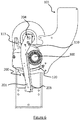
- the figure 5e shows an arrangement of the arm which allows this aspect, with a finger 210 attached under the body of the arm 200 and forming, by its edge, the stop 213.
Landscapes
- Engineering & Computer Science (AREA)
- General Engineering & Computer Science (AREA)
- Toys (AREA)
- Portable Nailing Machines And Staplers (AREA)
Description
La présente invention est relative notamment à une machine de lancement d'au moins une cible permettant de lancer ladite cible suivant une trajectoire précise et répétée. Un tel dispositif de lancement de cibles est connu du document
Une application préférée concerne l'industrie du sport de tir et en particulier au balltrap.A preferred application relates to the shooting sport industry and in particular to balltrap.
Dans le domaine de l'industrie du sport de tir, les machines de lancement de cibles sont bien connues. Plusieurs modèles de lanceur de cibles existent et dans de nombreux cas, la précision de l'éjection de la cible n'est pas requise. C'est souvent notamment le cas des lanceurs de cibles présentant une mobilité en rotation. Pour ces appareils, la machine de lancement de cibles n'a besoin que d'une plaque de lancement, d'un bras de lancement et éventuellement d'un élément de guidage pour guider la cible.In the field of the shooting sport industry, target launching machines are well known. Several models of target launchers exist and in many cases, precision of target ejection is not required. This is often the case with target launchers with rotating mobility. For these devices, the target launching machine only needs a launching plate, a launching arm and possibly a guide element to guide the target.
En revanche, lorsque les lanceurs de cibles sont fixes, la répétabilité des trajectoires est plus souvent exigée. Par exemple, pour des disciplines olympiques ou pour les « parcours de chasse » la répétition d'une trajectoire par un lanceur est primordiale pour permettre une compétition équitable. En effet, dans ces disciplines on cherche à évaluer les concurrents uniquement selon leur adresse au tir. Ainsi, il ne doit pas y avoir de discrimination entre les concurrents par le biais de cibles plus ou moins difficiles à atteindre ou à la trajectoire variable.On the other hand, when the target launchers are fixed, the repeatability of the trajectories is more often required. For example, for Olympic disciplines or for "hunting courses" the repetition of a trajectory by a launcher is essential to allow fair competition. Indeed, in these disciplines one seeks to evaluate the competitors solely according to their marksmanship. Thus, there should be no discrimination between competitors through targets that are more or less difficult to reach or with a variable trajectory.
Ces machines fixes intègrent ainsi par exemple une butée mobile et un élément de guidage.These stationary machines thus integrate, for example, a movable stop and a guide element.
La fonction principale de la butée mobile est de maintenir la cible appliquée au bras de lancement grâce à un ressort de rappel. Le maintien de la cible sur le bras de lancement permet d'éviter les chocs susceptibles de briser la cible lors de l'accélération brutale du bras pour l'éjection de la cible.The main function of the mobile stop is to keep the target applied to the launch arm by means of a return spring. Maintaining the target on the launching arm makes it possible to avoid shocks liable to break the target during the sudden acceleration of the arm for ejecting the target.
Accessoirement le roulement de la cible au contact de la butée mobile et du bras de lancement permet de rabattre la cible contre l'élément de guidage.Incidentally the rolling of the target in contact with the movable stop and the launching arm makes it possible to fold the target against the guide element.
Cette solution, est efficace lorsque le pourtour de la cible est parfaitement lisse, et que la plaque de lancement est parfaitement sèche. En effet, lorsque la plaque de lancement et/ou le pourtour de la cible ont une adhérence accrue, comme par exemple lors de présence d'eau sur la plaque de lancement, la cible ne se positionne pas contre l'élément de guidage. Cela modifie alors la trajectoire attendue de la cible.This solution is effective when the periphery of the target is perfectly smooth, and the launch pad is perfectly dry. In fact, when the launching plate and / or the periphery of the target have increased adhesion, as for example when water is present on the launching plate, the target does not position itself against the guide element. This then changes the expected trajectory of the target.
Il existe donc une demande pour améliorer la précision de l'éjection d'une cible par une machine de lancement de cibles.There is therefore a demand to improve the precision of the ejection of a target by a target launching machine.
L'invention permet de résoudre tout ou partie des inconvénients des techniques actuelles.The invention overcomes all or part of the drawbacks of current techniques.
L'invention concerne une machine de lancement comme décrite dans la revendication 1.The invention relates to a launching machine as described in claim 1.
De façon avantageuse, cette machine est telle que le bras de lancement comprend un doigt doté d'une partie de contact configurée pour s'appliquer sur une quatrième portion du pourtour de la cible dans la position armée, la quatrième portion étant distincte des première, deuxième et troisième portions.Advantageously, this machine is such that the launching arm comprises a finger provided with a contact part configured to be applied on a fourth portion of the periphery of the target in the armed position, the fourth portion being distinct from the first, second and third portions.
Cette disposition permet avantageusement d'appliquer une quatrième contrainte à la cible. Cette contrainte va obliger la cible à se positionner à une position précise le long du bras de lancement. Et ceux peu important la forme du pourtour de la cible, ou de la plaque de lancement. La force exercée par le doigt de lancement permet ainsi d'éviter les effets de ventouse par exemple lorsque la plaque de lancement est mouillée.This arrangement advantageously makes it possible to apply a fourth constraint to the target. This constraint will force the target to position itself at a precise position along the launching arm. And those little important the shape of the periphery of the target, or the launching plate. The force exerted by the launching finger thus makes it possible to avoid the effects of suction cups, for example when the launching plate is wet.
L'invention concerne aussi une machine dans laquelle la partie de contact est configurée pour exercer un appui sur la cible ayant une composante non nulle en direction de l'élément de guidage.The invention also relates to a machine in which the contact part is configured to exert pressure on the target having a non-zero component towards the guide element.
Avantageusement et toujours dans le but de garantir à la cible une position de départ le long du bras de lancement identique, la partie de contact va pousser la cible contre l'élément de guidage.Advantageously and always with the aim of guaranteeing the target a starting position along the identical launching arm, the contact part will push the target against the guide element.
Ainsi, la cible se retrouve en butée contre l'élément de guidage, le bras de lancement et le doigt. La position précise permettant ce contact simultanée est unique. Ainsi, la cible est toujours positionnée au même endroit du bras de lancement.Thus, the target finds itself in abutment against the guide element, the launching arm and the finger. The precise position allowing this simultaneous contact is unique. Thus, the target is always positioned in the same place of the launching arm.
D'autres caractéristiques, buts et avantages de la présente invention apparaitront à la lecture de la description détaillée qui suit, et en regard des dessins annexés donnés à titre d'exemples non limitatifs et sur lesquels :
- la
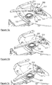
figure 1 montre une réalisation préférée de l'invention et dans laquelle le doigt comprend une portion de contact rectiligne ; - la
figure 2 est une vue de dessus d'une réalisation alternative de l'invention dans laquelle le doigt à une forme de coude. - Les
figures 3a à 3e montrent les vues d'étapes, permettant de passer d'une étape d'approvisionnement en cible à une position armée de la machine de lancement de cibles. Ces vues montrent ces étapes incluant une première réalisation de l'invention. - Les
figures 4a à 4f montrent les vues d'étapes, permettant de passer d'une étape d'approvisionnement en cible à l'éjection de la cible. Ces vues montrent ces étapes incluant une réalisation alternative de l'invention. - Les
figures 5a à 5d illustrent des étapes successives d'un autre mode de réalisation de l'invention ; lafigure 5e est une vue en écorché de lafigure 5d ; - La
figure 6 montre une machine de l'art antérieur.
- the
figure 1 shows a preferred embodiment of the invention and in which the finger comprises a rectilinear contact portion; - the
figure 2 is a top view of an alternative embodiment of the invention in which the finger has an elbow shape. - The
figures 3a to 3e show the step views, allowing you to move from a target supply step to an armed position of the target launch machine. These views show these steps including a first embodiment of the invention. - The
figures 4a to 4f show step views, allowing you to move from a target supply step to target ejection. These views show these steps including an alternative embodiment of the invention. - The
figures 5a to 5d illustrate successive steps of another embodiment of the invention; thefigure 5e is a cutaway view of thefigure 5d ; - The
figure 6 shows a machine of the prior art.
Avant d'entrer dans le détail de formes préférées de réalisation de l'invention en référence aux dessins notamment, d'autres caractéristiques optionnelles de l'invention, qui peuvent être mises en oeuvre de façon combinée selon toutes combinaisons ou de manière alternative, sont indiquées ci-après :
- la partie de contact est configurée pour exercer un appui sur la cible ayant une composante non nulle en direction de la butée mobile ;
- la partie de contact du doigt est située plus près de l'axe de rotation du bras de lancement que la partie d'éjection dudit bras de lancement ;
- la partie de contact est rectiligne ;
- la partie d'éjection est rectiligne suivant un axe longitudinal ;
- l'axe longitudinal et la partie de contact du doigt forment un angle α non nul.
- l'angle α est compris entre 5° et 45°, de préférence entre 8° et 16° et de préférence 12° ;
- le doigt comprend un corps allongé dont une portion distale forme au moins en partie la partie de contact ;
- Le doigt est formé d'une pièce monolithique
- le coefficient de frottement de la partie d'éjection sur la cible est supérieur à celui de la partie de contact du doigt sur la cible ;
- la matière du doigt est avantageusement un alliage d'aluminium ;
- la butée mobile est configurée pour exercer une force sur la deuxième portion du pourtour de la cible en direction de la partie d'éjection du bras de lancement ;
- au moins le contact de la machine sur au moins l'une parmi les première, deuxième, troisième et quatrième portions est ponctuel dans un plan parallèle à un plan de plaque de lancement. ;
- la fin de l'étape de passage position armée du bras de lancement déclenche automatiquement la deuxième rotation ;
- la deuxième rotation est déclenchée manuellement par un utilisateur.
- la machine comprend un dispositif de libération de la cible 300 configuré pour que la butée mobile 110 ne s'applique plus sur la cible 300 dans une position angulaire prédéfinie du
bras 200 située en aval de la position armée suivant le sens de rotation dubras 200 ; - le dispositif de libération comprend une première butée 117 portée par la butée mobile 110 et une deuxième butée 213 portée par le
bras 200, la deuxième butée 213 étant configurée pour exercer une poussée sur la première butée 117 à partir de la position angulaire prédéfinie ; - la deuxième butée 213 est située sur le doigt 210 ;
- la deuxième butée 213 est configurée pour ne plus exercer la poussée sur la première butée 117 après un secteur angulaire prédéterminé suivant la position angulaire prédéfinie ;
- la position angulaire prédéfinie est configurée pour correspondre à une position de la cible 300 au contact d'une partie située au niveau ou en amont d'une extrémité distale 122 de l'élément de guidage 120.
- the contact part is configured to exert pressure on the target having a non-zero component in the direction of the movable stop;
- the contact part of the finger is located closer to the axis of rotation of the launch arm than the ejection part of said launch arm;
- the contact part is straight;
- the ejection part is rectilinear along a longitudinal axis;
- the longitudinal axis and the contact part of the finger form a non-zero angle α.
- the angle α is between 5 ° and 45 °, preferably between 8 ° and 16 ° and preferably 12 °;
- the finger comprises an elongated body, a distal portion of which at least partially forms the contact portion;
- The finger is formed of a monolithic piece
- the coefficient of friction of the ejection part on the target is higher than that of the contact part of the finger on the target;
- the material of the finger is advantageously an aluminum alloy;
- the movable stopper is configured to exert a force on the second portion of the periphery of the target in the direction of the ejection part of the launching arm;
- at least the contact of the machine on at least one of the first, second, third and fourth portions is punctual in a plane parallel to a plane of launching plate. ;
- the end of the armed position transition stage of the launching arm automatically triggers the second rotation;
- the second rotation is triggered manually by a user.
- the machine comprises a
target release device 300 configured so that themovable stop 110 no longer applies to thetarget 300 in a predefined angular position of thearm 200 located downstream of the armed position in the direction of rotation of thearm 200 ; - the release device comprises a
first stop 117 carried by themovable stop 110 and asecond stop 213 carried by thearm 200, thesecond stop 213 being configured to exert a thrust on thefirst stop 117 from the predefined angular position; - the
second stop 213 is located on thefinger 210; - the
second stop 213 is configured to no longer exert the thrust on thefirst stop 117 after a predetermined angular sector according to the predefined angular position; - the predefined angular position is configured to correspond to a position of the
target 300 in contact with a part situated at or upstream of adistal end 122 of theguide element 120.
Pour la bonne compréhension de l'invention, on entendra par :
- Doigt : pièce de forme quelconque servant d'appui ou d'arrêt à une autre ;
- Trajectoire d'éjection : la trajectoire suivie par une cible lors de son éjection ;
- Faible coefficient de frottement : un coefficient de frottement inférieur à celui de l'aluminium sur une cible, notamment un pigeon d'argile.
- Finger: piece of any shape serving as support or stop for another;
- Ejection trajectory: the trajectory followed by a target during its ejection;
- Low coefficient of friction: a coefficient of friction lower than that of aluminum on a target, in particular a clay pigeon.
L'invention est relative à une machine de lancement d'au moins une cible ayant une trajectoire d'éjection reproductible. Le but de l'invention est ainsi de contrôler avec précision la trajectoire d'éjection de la cible.The invention relates to a machine for launching at least one target having a reproducible ejection trajectory. The object of the invention is thus to precisely control the ejection trajectory of the target.
La machine de lancement de cibles comprend ainsi avantageusement, une plaque de lancement 100 et un bras de lancement 200 ainsi qu'au moins une cible
300. De manière avantageuse, les cibles 300 sont comprises dans un magasin (non visible sur les figures). Ce magasin peut notamment être un barillet à plusieurs colonnes en empilement de cibles. Ainsi, la machine peut embarquer un grand nombre de cibles 300. Cela est particulièrement utile lors des compétitions ou des parcours de chasse. Dans la réalisation préférée de l'invention, le magasin approvisionne le bras de lancement 200 avec une seule cible 300 à la fois.
On donne ci-après des exemples de composants de l'invention, de façon non limitative.The target launching machine thus advantageously comprises a
300. Advantageously, the
Examples of components of the invention are given below, without implied limitation.
La cible 300 peut être du type « pigeon d'argile » et est de préférence susceptible d'être rompue lorsque le tireur l'atteint. La cible 300 comprend un pourtour 301, une face inférieure et une face supérieure de la cible 302. Avantageusement, la cible est à base de résines. Le pourtour 301 de la cible 300 correspond à la portion de liaison entre la face inférieure et la face supérieure de la cible 302. Ainsi, le pourtour 301 de la cible correspond à la dimension en épaisseur de la cible 300. Avantageusement et de préférence, les faces supérieure 302 et inférieure sont parallèles. Dans une réalisation de l'invention la face supérieure 302 et la face inférieure de la cible sont de diamètres identiques. Dans cette réalisation le pourtour 301 est avantageusement compris dans un plan perpendiculaire au plan comprenant les faces supérieures 302 et inférieures de la cible 300.The
Dans une autre réalisation préférée de la cible 300 la face supérieure 302 à un diamètre inférieure à celui de la face inférieure. Dans cette hypothèse, le pourtour 301 peut être circulaire et de tranche rectiligne ou non. Lorsque la tranche du pourtour 301 n'est pas rectiligne elle peut avantageusement comprendre au moins une marche et de préférence une succession de marches, configurée pour réduire le diamètre du pourtour en direction de la face supérieure.In another preferred embodiment of the
Le support de lancement comprend une plaque de lancement 100, une butée mobile 110 et un élément de guidage 120.The launching support comprises a
Avantageusement, la plaque de lancement 100 comprend une bordure distale 103, une bordure proximale 104, une première partie 101, une seconde partie 102, une bordure intérieure 105, et une bordure extérieure 106Advantageously, the launching
De manière préférentielle, la plaque de lancement 100 est plate. Elle comprend avantageusement une première partie 101 et une seconde partie 102. La seconde partie 102 comprend préférentiellement la bordure distale 103 de la plaque de lancement 100, ladite bordure distale 103 correspondant à l'extrémité non reliée à la machine. Lors de l'éjection d'une cible 300, la dernière partie de la machine en contact avec la cible 300 sera ladite seconde partie 102. Afin de garantir une vitesse et une trajectoire les plus parfaites possibles, la seconde partie 102 est lisse. Le but étant ici d'éviter au maximum les déviations de trajectoire dû à des obstacles ou des aspérités.Preferably, the launching
Dans une réalisation préférée, la seconde partie 102 est en inox ou en acier avec un revêtement de zinc.In a preferred embodiment, the
La première partie 101 est quant à elle reliée à la machine. Elle comprend avantageusement l'extrémité proximale de la plaque de lancement 104. C'est ladite première partie 101 qui va accueillir la cible 300 au moment de l'approvisionnement par le magasin, et c'est aussi cette première partie 101 qui va avantageusement supporter la butée mobile 110 et l'élément de guidage 120. Dans d'autres réalisations de l'invention, la butée mobile 110 et l'élément de guidage 120 sont portés par le châssis de la machine et non pas par la plaque de lancement 100.The
La plaque de lancement 100 est préférentiellement en métal, ou en alliage métallique. Ainsi, la plaque peut être en acier, aluminium ou en matériaux composites.The launching
Avantageusement la plaque de lancement 100 à une forme sensiblement coudée. Cette forme coudée permet à la cible 300 d'avoir un support durant toute la rotation du bras de lancement 200. Néanmoins, dans des réalisations alternatives de l'invention, la plaque de lancement 100 à une forme différente. Elle peut par exemple être d'une forme de losange.Advantageously, the launching
Dans la réalisation préférée, et du fait de sa forme sensiblement coudée, les bordures s'étendant entre la bordure distale 103 et la bordure proximale 104 ne sont pas de tailles identiques.In the preferred embodiment, and because of its substantially bent shape, the edges extending between the
Avantageusement on appellera bordure intérieure 105, la bordure s'étendant entre la bordure distale 103 et la bordure proximale 104 dont la taille est la plus petite.
Inversement on appellera bordure extérieure 106 la bordure reliant la bordure proximale 104 et la bordure distale 103 dont la taille est la plus grande.Advantageously, the
Conversely, the
Enfin, dans la réalisation préférée, la première partie 101 et la seconde partie 102 représentent chacune 50% de la surface totale de la plaque de lancement 100. Suivant d'autres modes de réalisation la répartition entre première partie 101 et seconde partie 102 n'est pas identique.Finally, in the preferred embodiment, the
Avantageusement, la butée mobile 110 comprend une surface extérieure 111, une surface intérieure 112, un élément de rappel 113, une extrémité distale 114, une extrémité proximale 115 ainsi qu'un axe de rotation 116.Advantageously, the
La butée mobile 110 est avantageusement positionnée sur la première partie 101 de la plaque de lancement 100. Plus précisément, la butée mobile 110 est positionnée aux abords de la bordure intérieure 105 sur la première partie 101.The
La butée mobile 110 comprend avantageusement une surface intérieure 112, une surface extérieure 111, une extrémité distale 114, une extrémité proximale 115 ainsi qu'un élément de rappel 113 et un axe de rotation 116.The
La butée mobile 110 a avantageusement la forme d'une griffe. Ainsi l'extrémité proximale 115 de la butée mobile 110 est l'extrémité la plus proche de la bordure proximale 104 de la plaque de lancement 100. Inversement, l'extrémité distale 114 de la butée mobile 110 est l'extrémité la plus éloignée de l'extrémité proximale 115.The
Avantageusement, entre les deux extrémités, la butée mobile 110 dispose d'une partie sensiblement rectiligne et d'une partie courbée. L'extrémité proximale 115 est dans cette configuration l'extrémité incluse dans la partie sensiblement rectiligne. L'extrémité distale 114 est quant à elle l'extrémité opposée, c'est-à-dire l'extrémité de la partie courbée. La butée mobile 110 ayant préférentiellement une partie courbée, les surfaces intérieure et extérieure reliant chacune des extrémités n'ont pas une longueur identique. De ce fait, on appelle surface extérieure 111, la surface la plus longue. Avantageusement la surface extérieure 111 est orientée en vis-à-vis de la première partie 101 de la plaque de lancement 100. Inversement, la surface intérieure 112 comprend la dimension la plus faible entre les deux extrémités de la butée mobile 110. La surface intérieure 112 est dans cette réalisation tournée vers la bordure extérieure 106 de la plaque de lancement 100.Advantageously, between the two ends, the
L'extrémité distale 114 de la butée mobile 110 va être en contact avec la cible 300. Et de préférence c'est la surface intérieure 112 de l'extrémité distale 114 qui est en contact avec une deuxième portion du pourtour 301 de la cible 300.The
La butée est montée en rotation sur la première partie 101 de la plaque de lancement 100. Pour ce faire, ladite butée comprend, sur la partie sensiblement rectiligne aux abords de la partie courbée, un axe de rotation 116 visible en
Avantageusement, l'extrémité proximale 115 de la butée mobile 110 est raccordée à une première extrémité de l'élément de rappel 113. La seconde extrémité de l'élément de rappel 113 étant avantageusement fixée à la plaque de lancement 100.Advantageously, the
De manière préférentielle, la fixation de l'élément de rappel 113 s'effectue sur la première partie 101 de la plaque de lancement 100. Plus précisément, cet élément de rappel 113 est fixé aux abords de la jonction entre la bordure intérieure 105 et la bordure proximale 104 de la plaque de lancement 100. L'élément de rappel 113 comprend une partie déformable ayant un coefficient d'élasticité important. Au repos, l'élément de rappel 113 est configuré pour maintenir la butée de rappel dans une première position. Par exemple, l'élément de rappel 113 peut être un ressort.Preferably, the
En action, lorsque la butée mobile 110 passe d'une première position à une deuxième position, l'élément de rappel 113 est configuré pour ramener la butée mobile
110 de la deuxième position à la première position. De manière avantageuse et non limitative, on entendra par passage d'une première position au passage d'une deuxième position de la butée mobile 110, le déplacement de l'extrémité proximale 115 de la butée mobile 110 en direction de la bordure extérieure 106 de la plaque de lancement 100. Dans cette configuration, lorsque l'extrémité proximale 115 de la butée mobile 110 effectue un mouvement en direction de la bordure extérieure 106, l'extrémité distale 114 de la butée mobile 110 effectue un mouvement en direction de la bordure intérieure 105 de la plaque de lancement 100. Ce mouvement étant de préférence articulé autour d'un axe de rotation 116.In action, when the
110 from the second position to the first position. Advantageously and without limitation, by passing from a first position to passing from a second position of the
Avantageusement, toutes ces caractéristiques de la butée mobile 110 permettent à ladite butée mobile 110 d'exercer un point de pression sur le pourtour 301 de la cible 300 dans la direction de la bordure proximale 104 de la plaque de lancement 100.Advantageously, all of these characteristics of the
Suivant une option visible aux
Avantageusement la plaque de lancement 100 comprend aussi un élément de guidage 120. L'élément de guidage 120 est positionné sur la première partie 101 de la plaque de lancement 100. Dans chacune de ces réalisations, et de manière préférentielle l'élément de guidage 120 se trouve à proximité de la bordure extérieure 106 de la plaque de lancement 100.Advantageously, the launching
Avantageusement, l'élément de guidage 120 est curviligne concave et de préférence un arc de cercle. Le but de l'élément de guidage 120 est de guider la cible
300 lors de son éjection par le bras de lancement 200. De manière préférentielle l'élément de guidage 120 est maintenue à la plaque de lancement 100 par au moins deux vis, dont une vis à l'extrémité de l'élément de guidage 120 la plus proche de la bordure distale 103 de la plaque de lancement 100. De manière préférentielle, l'élément de guidage 120 est fait d'un matériau à faible coefficient de frottement.Advantageously, the
300 during its ejection by the launching
Dans une autre réalisation de l'invention l'élément de guidage 120 est fait d'un matériau quelconque, mais comprend un revêtement à faible coefficient de frottement.
Le contact entre l'élément de guidage 120 et la cible 300 se fait avantageusement sur une première portion du pourtour 301 de la cible 300.In another embodiment of the invention the
The contact between the
Le bras de lancement 200 comprend avantageusement une partie d'éjection 201, une partie de fixation 202 et un doigt 210.
Avantageusement la partie de fixation 202 comprend un axe de rotation du bras de lancement 204. Cet axe de rotation du bras de lancement 204 est, dans une réalisation préférée de l'invention, situé à l'extérieur de la bordure intérieure 105 de la première partie 101 de la plaque de lancement 100. La liaison entre le bras de lancement 200 et la machine de lancement s'effectue par le biais de cet axe de rotation 204. Dans une autre réalisation de l'invention, l'axe de rotation du bras de lancement 204 est porté par la plaque de lancement 100.The launching
Advantageously, the fixing
Avantageusement l'axe de rotation 204 du bras de lancement est perpendiculaire au plan comprenant la plaque de lancement 100. De manière préférentielle, le bras de lancement 200 est compris dans un plan parallèle au plan comprenant la plaque de lancement 100 et de préférence au-dessus de ce dernier.Advantageously, the axis of
La partie d'éjection 201 du bras de lancement 200 peut comprendre une portion de contact 206 configurée pour s'appliquer sur la cible lors de sa poussée. Avantageusement, la partie d'éjection 201 est rectiligne suivant un axe longitudinal 205. L'axe longitudinal 205 s'étend de préférence selon la dimension en longueur du bras de lancement 200. Avantageusement, l'axe longitudinal 205 est perpendiculaire avec l'axe de rotation du bras de lancement 204.The
Par exemple, la portion de contact 206 est une surface du bras de lancement 200 en contact avec la cible 300. De préférence le contact entre la cible 300 et le bras de lancement 200 s'effectue sur une quatrième portion du pourtour 301 de la cible 300.For example, the
Dans une réalisation préférée, la portion de contact 206 comprend une réglette 203. Dans cette réalisation, la réglette 203 s'interpose entre la cible 300 et la portion de contact 206. C'est notamment cette réalisation qui est représentée dans les figures. De manière avantageuse et non exhaustive la réglette 203 est constituée d'un matériau à fort coefficient de frottement ou comprend un revêtement à fort coefficient de frottement. Le matériau ou le revêtement de la réglette 203 peut ainsi par exemple être un élastomère (caoutchouc, polyuréthane).In a preferred embodiment, the
Suivant un mode de réalisation, le bras 200 comprend un corps principal, par exemple métallique, relié à un arbre qui le motorise en rotation, au niveau de l'axe 204.According to one embodiment, the
Dans la réalisation préférée de l'invention, le doigt 210 est une pièce exerçant un appui supplémentaire sur la cible, notamment en modifiant l'angle entre la partie d'éjection 201 et la cible 300. Nous avons dit précédemment qu'une portion de la partie d'éjection 201 était de préférence rectiligne suivant avec un axe longitudinal 205. Elle possède ainsi un angle de 0°. Le doigt 210 dans la réalisation préférée de l'invention vient modifier cet angle sur une autre portion du bras. Le doigt 210 comprend dans un cas préféré une partie de contact 211 rectiligne. Ainsi la partie d'éjection 201 n'est plus suivant une seule ligne, mais comprend un angle appelé α. Cet angle α peut être compris entre 5° et 45° et est de préférence de 12°. L'angle α étant avantageusement tourné vers l'axe de rotation du bras de lancement 204.In the preferred embodiment of the invention, the
Le doigt 210 est avantageusement réalisé dans un matériau à faible coefficient de frottement, ou possède un revêtement à faible coefficient de frottement. Dans cette réalisation, le doigt 210 peut être un élément rapporté fixé au bras de lancement 200 de plusieurs manières. Par exemple une partie du doigt 210 peut se prolonger sous le bras de lancement 200 et se fixer par-dessous. Par exemple, si le bras 200 comporte un corps principal, le doigt 210 peut être rapporté sur la face inférieure du corps ; il forme alors une surépaisseur du bras 200, dirigée en regard de la plaque de lancement 100. La
Dans une autre hypothèse le doigt 210 peut se fixer directement sur la tranche du bras de lancement 200. En tout état de cause, le doigt 210 est en contact avec une quatrième portion du pourtour 301 de la cible 300. Avantageusement, cette modification de l'angle de la partie en contact avec la cible 300 permet, lors de la rotation du bras de lancement 200, d'exercer une force sur la cible 300 déplaçant ladite cible 300 vers l'élément de guidage 120. Et plus précisément vers l'extrémité de l'élément de guidage la plus proche de la bordure distale 103 de la plaque de lancement 100.In another hypothesis, the
L'avantage de cette réalisation est que le doigt 210 est adapté à tous les diamètres de cibles.The advantage of this embodiment is that the
Enfin, dans une autre réalisation, le doigt 210 et le bras de lancement 200 sont formés d'une pièce monolithique.Finally, in another embodiment, the
Dans une troisième réalisation de l'invention, le doigt 210 est réalisé par un élément allongé, par exemple en forme de coude. Dans cette réalisation le doigt 210 comprend une extrémité de contact avec la cible. Avantageusement cette extrémité de contact est réalisée dans un matériau ou comprend un revêtement à faible coefficient de frottement. De plus, une roulette peut être présente à l'extrémité de contact afin de réaliser ledit contact. Dans cette réalisation l'extrémité du doigt 210 opposée à l'extrémité de contact est montée sur bras de lancement 200. De plus, cette autre extrémité s'articule de préférence autour d'un axe de rotation du doigt. L'axe de rotation du doigt étant parallèle à l'axe de rotation du bras 204. Dans cette réalisation le coude est orienté vers la bordure intérieure 105 de la plaque de lancement 100. Cette forme coudée a pour principale avantage d'accentuer la poussée du doigt 210 contre la cible 300 dans la direction de l'élément de guidage 120.In a third embodiment of the invention, the
Le but du doigt 210 étant toujours de forcer la cible 300 à se positionner contre l'élément de guidage 120. Dans cette réalisation, le doigt 210 est avantageusement articulé en rotation afin de s'adapter à tous les diamètres de cibles. L'adaptation audit diamètre peut se faire manuellement. Dans ce cas, un utilisateur règle le doigt 210 pour que son extrémité de contact prenne appui sur la cible 300 et serre l'autre extrémité du doigt par le biais par exemple d'une vis et d'un écrou.The purpose of the
Dans la suite de la description, on donne d'autres variantes de réalisation du doigt 210, notamment en référence aux
Selon la réalisation préférée, la surface inférieure de la cible 300 est comprise dans un plan parallèle au plan comprenant la plaque de lancement 100. Néanmoins, la cible 300, reposant sur la plaque de lancement 100, se trouve au-dessus de ladite plaque de lancement.According to the preferred embodiment, the lower surface of the
Avantageusement mais non limitativement, la butée mobile 110 et plus particulièrement l'extrémité distale 114 et l'élément de guidage 120 et plus particulièrement la surface intérieure de l'élément de guidage 121 sont dans un plan similaire, et parallèle au plan de la plaque de lancement 100. Ce plan est positionné relativement à la cible 300 au-dessus de la surface inférieure, mais sur une partie basse du pourtour 301 de la cible 300. Ainsi, les contacts des première et la deuxième portions du pourtour 301 de la cible 300 avec la surface intérieure de l'élément de guidage 121 et l'extrémité distale 114 se font sur la partie basse du pourtour 301 de la cible 300.Advantageously but not limited to, the
Dans l'hypothèse où le pourtour 301 de la cible 300 comprend au moins une marche, alors le contact entre la première et la deuxième portion du pourtour de la cible avec respectivement la surface intérieure de l'élément de guidage 121 et l'extrémité distale 114 se fait sur l'une des premières marches en partant de la surface inférieure de la cible. De préférence les contacts se font sur la première marche en partant de la surface inférieure de la cible.In the hypothesis where the
Dans la réalisation préférée de l'invention, la partie d'éjection 201 et le doigt 210 sont prévus pour un appui dans un même plan et parallèle au plan de la plaque de lancement 100. Dans cette réalisation, la partie d'éjection 201 et le doigt 210 prennent contact respectivement sur la troisième et la quatrième portion du pourtour 301 de la cible 300. La troisième et la quatrième portions sont avantageusement situées sur une partie haute du pourtour 301 et donc au-dessus des première et deuxième portions du pourtour 301 de la cible 300. Dans une réalisation alternative de l'invention, le bras de lancement 200 et le doigt 210 sont compris dans des plans parallèles situés l'un au- dessus de l'autre. Dans cette réalisation, le doigt 210 est avantageusement sur le bras de lancement 200.In the preferred embodiment of the invention, the
D'autres réalisations sont bien entendu possibles pour le fonctionnement de l'invention comme par exemple en attribuant des plans indépendants et parallèles à la partie d'éjection, au doigt 210, la surface intérieure de l'élément de guidage 121 et à l'extrémité distale 114. Néanmoins, dans toutes ces réalisations, le bras de lancement 200 et le doigt 210 est dans un ou des plans situés au-dessus du ou des plans de l'extrémité distale 114 et de la surface intérieure de l'élément de guidage 121. Le but de ce décalage est que lors de la rotation du bras de lancement 200, ce dernier peut passer au-dessus de l'élément de guidage 120 et de la butée mobile 110.Other embodiments are of course possible for the operation of the invention, for example by assigning independent and parallel planes to the ejection part, to
D'une manière générale, il convient que les quatre portions d'appui de la cible soient situées sur des zones de la cible angulairement distinctes. C'est-à-dire à des endroits différents de ce pourtour 301 avantageusement circulaire. L'utilisation de la machine de lancement de cibles comprend avantageusement une étape d'approvisionnement, une étape de passage en position armée du bras de lancement 200 et une position d'éjection de la cible 300.In general, the four support portions of the target should be located on angularly distinct areas of the target. That is to say at different locations from this advantageously
Au début de l'étape d'approvisionnement (
Dans une autre réalisation de l'invention, le pourtour 301 de la cible est en contact avec la bordure proximale 104 de la plaque de lancement 100 et l'extrémité proximale 115 de la butée mobile 110.In another embodiment of the invention, the
Le bras de lancement 200 va ensuite effectuer une première rotation. Le sens de cette rotation ayant pour but de rapprocher la partie d'éjection 201 du bras de lancement 200 de la bordure distale 103 de la plaque de lancement 100 en passant au-dessus de l'élément de guidage 120.The launching
Lors de cette première rotation le doigt 210 va entrer en contact avec la quatrième portion du pourtour de la cible 300 (
L'élément de guidage 120 et plus précisément vers la surface intérieure de l'élément de guidage 121 entre ensuite en contact avec la deuxième portion du pourtour 301 de la cible 300 (
L'étape d'éjection de la cible 300 peut être automatiquement réalisée à la suite de l'étape d'armement du bras de lancement. Elle peut aussi, dans une autre réalisation de l'invention, être déclenchée manuellement par un utilisateur. Lors de l'étape d'éjection, le bras de lancement 200 va réaliser une deuxième rotation dans un sens similaire à la première. Lors de cette deuxième rotation, la cible 300 va rouler le long de l'élément de guidage et perdre son contact avec le doigt 210 et la butée mobile110. Ainsi la cible va passer avantageusement sur la seconde partie 102 de la plaque de lancement 100 en direction de la bordure distale 103, et donc du côté de la surface extérieure 111 de la butée mobile (
Les
La butée mobile 110 comporte une première butée 117 configurée pour coopérer par contact avec la deuxième butée 213. Dans le cas illustré, la première butée 117 est un doigt faisant saillie sur le corps de la butée mobile 110 en direction du bras 200. De préférence, la première butée 117 est positionnée sur la butée mobile 110 entre l'axe de rotation 116 et l'extrémité distale 114.The
Dans le cas représenté aux
La
Ultérieurement, avec la poursuite de la rotation du bras 200, avec le déplacement relatif de la première butée 117 le long de la deuxième butée 213, la première butée 117 parvient progressivement à la deuxième extrémité 215 de la deuxième butée 213. En dépassant l'extrémité 215, la butée 117 se retrouve plus contrainte par le déplacement du bras 200 et peut reprendre sa position initiale par l'application de l'effet de rappel du ressort 113. On notera que la première butée 117 est avantageusement configurée pour ne pas interférer avec d'autres parties du bras 200 au cours de la suite de la rotation. À cet effet, par exemple, la butée 117 peut ne faire saillie au-delà du corps de la butée mobile 110 que sur une épaisseur telle que la butée 117 ne franchit pas l'épaisseur de la tranche du doigt 210. La
L'invention n'est pas limitée aux modes de réalisation précédemment décrits mais s'étend à tous modes de réalisation selon les revendications annexées.The invention is not limited to the embodiments previously described but extends to all embodiments according to the appended claims.
- 100.100.
- Plaque de lancementLaunch plate
- 101.101.
- Première partieFirst part
- 102.102.
- Seconde partieSecond part
- 103.103.
- bordure distaledistal border
- 104.104.
- Bordure proximaleProximal border
- 105.105.
- Bordure intérieureInner border
- 106.106.
- Bordure extérieureOuter border
- 110.110.
- Butée mobileMovable stop
- 111.111.
- Surface extérieureExternal surface
- 112.112.
- Surface intérieureInterior surface
- 113.113.
- Elément de rappelCallback element
- 114.114.
- Extrémité distaleDistal end
- 115.115.
- Extrémité proximaleProximal end
- 116.116.
- Axe de rotationRotation axis
- 117.117.
- Première butéeFirst stop
- 120.120.
- Elément de guidageGuide element
- 121.121.
- Surface intérieur de l'élément de guidageInner surface of the guide element
- 122.122.
- Extrémité distaleDistal end
- 200.200.
- Bras de lancementLaunch arm
- 201.201.
- Partie d'éjectionEjection section
- 202.202.
- Partie de fixationFixing part
- 203.203.
- RégletteStrip
- 204.204.
- Axe de rotation du bras de lancementThrowing arm rotation axis
- 205.205.
- Axe longitudinalLongitudinal axis
- 206.206.
- Portion de contactContact Portion
- 210.210.
- DoigtFinger
- 211.211.
- Partie de contactContact part
- 213.213.
- Deuxième butéeSecond stop
- 214.214.
- Première extrémitéFirst end
- 215.215.
- Deuxième extrémitéSecond end
- 300.300.
- CibleTarget
- 301.301.
- Pourtour de la ciblePerimeter of the target
- 302.302.
- Face supérieure de la cibleTop face of the target
Claims (15)
- Machine for launching at least one target (300) comprising:* a launching plate (100) configured to support a lower face of the target (300);* a launching arm (200) mobile in rotation about an axis of rotation (204) at least between a supply position, a reinforced position and an ejection position;* a guiding element (120) configured to be applied on a first portion of a perimeter (301) of the target (300) in the reinforced position;* a mobile abutment (110) configured to exert a force on a second portion of the perimeter (301) of the target (300) in the reinforced position;machine wherein the launching arm (200) comprises an ejection portion (201) configured to apply an ejection force on a third portion of the target (300) in the reinforced position, the first, second and third portions being separate,
characterised in that the launching arm (200) comprises a finger (210) equipped with a contact portion (211) being rectilinear and configured to be applied on a fourth portion of the perimeter (301) of the target (300) in the reinforced position, the fourth portion being separate from the first, second and third portions, the ejection portion (201) being rectilinear along a longitudinal axis (205), the longitudinal axis (205) and the contact portion (211) of the finger (210) forming a non-zero angle α. - Machine according to the preceding claim, wherein the contact portion (211) is configured to exert a bearing on the target (300) having a non-zero component in the direction of the guiding element (120).
- Machine according to the preceding claim, wherein the contact portion (211) is configured to exert a bearing on the target (300) having a non-zero component in the direction of the mobile abutment (110).
- Machine according to one of the preceding claims, wherein the contact portion (211) of the finger (210) is situated closer to the axis of rotation of the launching arm (204) than the ejection portion (201) of said launching arm (200).
- Machine according to any one of the preceding claims, wherein the angle α is between 5° and 45°, preferably between 8° and 16°, and preferably 12°.
- Machine according to any one of claims 1 to 4, wherein the finger (210) comprises an extended body of which a distal portion forms at least partially the contact portion (211).
- Machine according to any one of the preceding claims, wherein the friction coefficient of the ejection portion (201) on the target (300) is greater than that of the contact portion (211) of the finger (210) on the target (300).
- Machine according to the preceding claim, wherein the material of the finger (210) is an aluminium alloy.
- Machine according to any one of the preceding claims, wherein the mobile abutment (110) is configured to exert a force on the second portion of the perimeter (301) of the target (300) in the direction of the ejection portion (201) of the launching arm (200).
- Machine according to any one of the preceding claims, wherein at least the contact of the machine on at least one from among the first, second, third and fourth portions is specific in a plane parallel to a launching plate (100) plane.
- Machine according to any one of the preceding claims, comprising a device for releasing the target (300) configured such that the mobile abutment (110) is no longer applied on the target (300) in a predefined angular position of the arm (200) situated downstream from the reinforced position along the direction of rotation of the arm (200).
- Machine according to the preceding claim, wherein the release device comprises a first abutment (117) carried by the mobile abutment (110) and a second abutment (213) carried by the arm (200), the second abutment (213) being configured to exert a thrust on the first abutment (117) from the predefined angular position.
- Machine according to the preceding claim, wherein the second abutment (213) is situated on the finger (210).
- Machine according to one of the two preceding claims, wherein the second abutment (213) is configured to no longer exert the thrust on the first abutment (117) after a predetermined angular sector according to the predefined angular position.
- Machine according to one of the four preceding claims, wherein the predefined angular position is configured to correspond to a position of the target (300) in contact with a portion situated at the level of or upstream from a distal end (122) of the guiding element (120).
Applications Claiming Priority (2)
| Application Number | Priority Date | Filing Date | Title |
|---|---|---|---|
| FR1652090A FR3048772B1 (en) | 2016-03-14 | 2016-03-14 | MACHINE FOR LAUNCHING AT LEAST ONE TARGET |
| PCT/EP2017/056008 WO2017157946A1 (en) | 2016-03-14 | 2017-03-14 | Machine for launching at least one target |
Publications (2)
| Publication Number | Publication Date |
|---|---|
| EP3430347A1 EP3430347A1 (en) | 2019-01-23 |
| EP3430347B1 true EP3430347B1 (en) | 2020-06-17 |
Family
ID=56411714
Family Applications (1)
| Application Number | Title | Priority Date | Filing Date |
|---|---|---|---|
| EP17709723.5A Active EP3430347B1 (en) | 2016-03-14 | 2017-03-14 | Target launching machine |
Country Status (4)
| Country | Link |
|---|---|
| US (1) | US10690458B2 (en) |
| EP (1) | EP3430347B1 (en) |
| FR (1) | FR3048772B1 (en) |
| WO (1) | WO2017157946A1 (en) |
Families Citing this family (3)
| Publication number | Priority date | Publication date | Assignee | Title |
|---|---|---|---|---|
| FR3100879B1 (en) * | 2019-09-17 | 2022-04-15 | Laporte Holding | Target throwing device |
| FR3120433B1 (en) * | 2021-03-03 | 2023-01-27 | Laporte Holding | throwing arm |
| US11441879B1 (en) * | 2021-03-11 | 2022-09-13 | Bushnell Inc. | Trap machine with a spring manipulation mechanism |
Family Cites Families (9)
| Publication number | Priority date | Publication date | Assignee | Title |
|---|---|---|---|---|
| US2996058A (en) * | 1958-02-03 | 1961-08-15 | Remington Arms Co Inc | Magazine target trap |
| FR2296561A1 (en) | 1974-12-30 | 1976-07-30 | Monin Andre | Bicycle with tubular frame - has horizontal tube sloping downwards at rear end to join saddle support tube |
| US4146008A (en) | 1977-07-21 | 1979-03-27 | Remington Arms Company, Inc. | Target positioner for skeet trap |
| US5050575A (en) | 1990-02-06 | 1991-09-24 | Killion Darryl B | Disk launcher |
| FR2696538B1 (en) | 1992-10-07 | 1994-12-16 | Laporte Ball Trap Sarl | Improvement related to devices for launching targets or mobile targets. |
| FR2787181B1 (en) * | 1998-12-15 | 2001-05-25 | Laporte Ball Trap | APPARATUS FOR LAUNCHING TARGETS OF THE CLAY TRAY TYPE |
| US6276350B1 (en) | 2000-09-15 | 2001-08-21 | Laporte, Usa, Inc. | Variable angle target launcher |
| FR2993047B1 (en) | 2012-07-03 | 2015-04-10 | Laporte Holding | DEVICE FOR LAUNCHING TARGETS FOR INSTANT SPORTING SHOOTING OF THE TARGET |
| FR3016208B1 (en) * | 2014-01-08 | 2016-02-05 | Laporte Holding | DEVICE FOR LAUNCHING TARGETS FOR INSTANT START SPORTS SHOOTING WITH ACTIVE LOCKING ARRANGEMENTS ON THE LAUNCHING ARM ROTATION TREE |
-
2016
- 2016-03-14 FR FR1652090A patent/FR3048772B1/en not_active Expired - Fee Related
-
2017
- 2017-03-14 WO PCT/EP2017/056008 patent/WO2017157946A1/en active Application Filing
- 2017-03-14 EP EP17709723.5A patent/EP3430347B1/en active Active
- 2017-03-14 US US16/085,388 patent/US10690458B2/en active Active
Non-Patent Citations (1)
| Title |
|---|
| None * |
Also Published As
| Publication number | Publication date |
|---|---|
| FR3048772B1 (en) | 2018-09-28 |
| EP3430347A1 (en) | 2019-01-23 |
| US10690458B2 (en) | 2020-06-23 |
| WO2017157946A1 (en) | 2017-09-21 |
| FR3048772A1 (en) | 2017-09-15 |
| US20190154412A1 (en) | 2019-05-23 |
Similar Documents
| Publication | Publication Date | Title |
|---|---|---|
| EP2567178B1 (en) | Target launching device | |
| EP3430347B1 (en) | Target launching machine | |
| EP2652436B1 (en) | Target launching machine | |
| FR2906756A1 (en) | FIXED-POINT WRITING INSTRUMENT WITH RETRACTABLE PROTECTION SLEEVE | |
| EP2567182B1 (en) | Machine for launching targets with improved contact surfaces | |
| EP2567181B1 (en) | Target launching device | |
| EP2259006B1 (en) | Opening and locking system for an empennage of a munition | |
| EP1475601B1 (en) | Subcalibre projectile, rod and sabot constituting such a projectile | |
| EP3319667B1 (en) | Syringe and method for assembling it | |
| EP2567179B1 (en) | Target delivery device | |
| EP3489617B1 (en) | Projectile | |
| FR3018434A1 (en) | CASE SPECIALLY INTENDED TO CONTAIN A STICK, SUCH AS A LIP RED GRAPE, AND PRODUCT COMPRISING A BATCH PACKED IN SUCH A CASE. | |
| EP0350370B1 (en) | Automatic tool for placing inserts, especially of the bushing type | |
| EP1384970B1 (en) | Subcalibre projectile having multiple supports | |
| WO2015169874A1 (en) | Device for blocking access by a key to a lock cylinder and lock comprising such a device | |
| FR2666144A1 (en) | UNDER-CALIBER PROJECTILE WITH PROPULSION CAGE. | |
| EP4105591A1 (en) | Stationing device for a projectile | |
| EP1889668B1 (en) | Locking and unlocking mechanism for a paint roller | |
| FR2472166A1 (en) | DEVICE FOR A SEPARATOR EQUIPPING A FIREARM | |
| EP3569799A1 (en) | Locking control assembly | |
| FR2974893A1 (en) | Device for launching circular plastic target in archery, has discharging unit for discharging target to discharge region, which is arranged between two distinct planes respectively having rotation axes of launching arm and storage unit | |
| WO2018146243A1 (en) | Device for launching targets comprising a member for repositioning the targets before launch | |
| WO2011138341A1 (en) | Target launching machine | |
| FR2964187A1 (en) | DEVICE FOR LAUNCHING TARGETS FOR SHOOTING | |
| FR2882945A1 (en) | Paint applying sleeve locking/unlocking device for paint roller, has blade and hook presenting retaining neck positioned in groove whose walls are defined by annular shoulder and outer side of flange |
Legal Events
| Date | Code | Title | Description |
|---|---|---|---|
| STAA | Information on the status of an ep patent application or granted ep patent |
Free format text: STATUS: UNKNOWN |
|
| STAA | Information on the status of an ep patent application or granted ep patent |
Free format text: STATUS: THE INTERNATIONAL PUBLICATION HAS BEEN MADE |
|
| PUAI | Public reference made under article 153(3) epc to a published international application that has entered the european phase |
Free format text: ORIGINAL CODE: 0009012 |
|
| STAA | Information on the status of an ep patent application or granted ep patent |
Free format text: STATUS: REQUEST FOR EXAMINATION WAS MADE |
|
| 17P | Request for examination filed |
Effective date: 20180912 |
|
| AK | Designated contracting states |
Kind code of ref document: A1 Designated state(s): AL AT BE BG CH CY CZ DE DK EE ES FI FR GB GR HR HU IE IS IT LI LT LU LV MC MK MT NL NO PL PT RO RS SE SI SK SM TR |
|
| AX | Request for extension of the european patent |
Extension state: BA ME |
|
| DAV | Request for validation of the european patent (deleted) | ||
| DAX | Request for extension of the european patent (deleted) | ||
| GRAP | Despatch of communication of intention to grant a patent |
Free format text: ORIGINAL CODE: EPIDOSNIGR1 |
|
| STAA | Information on the status of an ep patent application or granted ep patent |
Free format text: STATUS: GRANT OF PATENT IS INTENDED |
|
| INTG | Intention to grant announced |
Effective date: 20191202 |
|
| GRAS | Grant fee paid |
Free format text: ORIGINAL CODE: EPIDOSNIGR3 |
|
| GRAA | (expected) grant |
Free format text: ORIGINAL CODE: 0009210 |
|
| STAA | Information on the status of an ep patent application or granted ep patent |
Free format text: STATUS: THE PATENT HAS BEEN GRANTED |
|
| AK | Designated contracting states |
Kind code of ref document: B1 Designated state(s): AL AT BE BG CH CY CZ DE DK EE ES FI FR GB GR HR HU IE IS IT LI LT LU LV MC MK MT NL NO PL PT RO RS SE SI SK SM TR |
|
| REG | Reference to a national code |
Ref country code: GB Ref legal event code: FG4D Free format text: NOT ENGLISH |
|
| REG | Reference to a national code |
Ref country code: CH Ref legal event code: EP |
|
| REG | Reference to a national code |
Ref country code: DE Ref legal event code: R096 Ref document number: 602017018302 Country of ref document: DE |
|
| REG | Reference to a national code |
Ref country code: IE Ref legal event code: FG4D Free format text: LANGUAGE OF EP DOCUMENT: FRENCH |
|
| REG | Reference to a national code |
Ref country code: AT Ref legal event code: REF Ref document number: 1281829 Country of ref document: AT Kind code of ref document: T Effective date: 20200715 |
|
| PG25 | Lapsed in a contracting state [announced via postgrant information from national office to epo] |
Ref country code: SE Free format text: LAPSE BECAUSE OF FAILURE TO SUBMIT A TRANSLATION OF THE DESCRIPTION OR TO PAY THE FEE WITHIN THE PRESCRIBED TIME-LIMIT Effective date: 20200617 Ref country code: LT Free format text: LAPSE BECAUSE OF FAILURE TO SUBMIT A TRANSLATION OF THE DESCRIPTION OR TO PAY THE FEE WITHIN THE PRESCRIBED TIME-LIMIT Effective date: 20200617 Ref country code: FI Free format text: LAPSE BECAUSE OF FAILURE TO SUBMIT A TRANSLATION OF THE DESCRIPTION OR TO PAY THE FEE WITHIN THE PRESCRIBED TIME-LIMIT Effective date: 20200617 Ref country code: GR Free format text: LAPSE BECAUSE OF FAILURE TO SUBMIT A TRANSLATION OF THE DESCRIPTION OR TO PAY THE FEE WITHIN THE PRESCRIBED TIME-LIMIT Effective date: 20200918 Ref country code: NO Free format text: LAPSE BECAUSE OF FAILURE TO SUBMIT A TRANSLATION OF THE DESCRIPTION OR TO PAY THE FEE WITHIN THE PRESCRIBED TIME-LIMIT Effective date: 20200917 |
|
| REG | Reference to a national code |
Ref country code: LT Ref legal event code: MG4D |
|
| REG | Reference to a national code |
Ref country code: NL Ref legal event code: MP Effective date: 20200617 |
|
| PG25 | Lapsed in a contracting state [announced via postgrant information from national office to epo] |
Ref country code: BG Free format text: LAPSE BECAUSE OF FAILURE TO SUBMIT A TRANSLATION OF THE DESCRIPTION OR TO PAY THE FEE WITHIN THE PRESCRIBED TIME-LIMIT Effective date: 20200917 Ref country code: RS Free format text: LAPSE BECAUSE OF FAILURE TO SUBMIT A TRANSLATION OF THE DESCRIPTION OR TO PAY THE FEE WITHIN THE PRESCRIBED TIME-LIMIT Effective date: 20200617 Ref country code: HR Free format text: LAPSE BECAUSE OF FAILURE TO SUBMIT A TRANSLATION OF THE DESCRIPTION OR TO PAY THE FEE WITHIN THE PRESCRIBED TIME-LIMIT Effective date: 20200617 Ref country code: LV Free format text: LAPSE BECAUSE OF FAILURE TO SUBMIT A TRANSLATION OF THE DESCRIPTION OR TO PAY THE FEE WITHIN THE PRESCRIBED TIME-LIMIT Effective date: 20200617 |
|
| REG | Reference to a national code |
Ref country code: AT Ref legal event code: MK05 Ref document number: 1281829 Country of ref document: AT Kind code of ref document: T Effective date: 20200617 |
|
| PG25 | Lapsed in a contracting state [announced via postgrant information from national office to epo] |
Ref country code: AL Free format text: LAPSE BECAUSE OF FAILURE TO SUBMIT A TRANSLATION OF THE DESCRIPTION OR TO PAY THE FEE WITHIN THE PRESCRIBED TIME-LIMIT Effective date: 20200617 Ref country code: NL Free format text: LAPSE BECAUSE OF FAILURE TO SUBMIT A TRANSLATION OF THE DESCRIPTION OR TO PAY THE FEE WITHIN THE PRESCRIBED TIME-LIMIT Effective date: 20200617 |
|
| PG25 | Lapsed in a contracting state [announced via postgrant information from national office to epo] |
Ref country code: IT Free format text: LAPSE BECAUSE OF FAILURE TO SUBMIT A TRANSLATION OF THE DESCRIPTION OR TO PAY THE FEE WITHIN THE PRESCRIBED TIME-LIMIT Effective date: 20200617 Ref country code: RO Free format text: LAPSE BECAUSE OF FAILURE TO SUBMIT A TRANSLATION OF THE DESCRIPTION OR TO PAY THE FEE WITHIN THE PRESCRIBED TIME-LIMIT Effective date: 20200617 Ref country code: SM Free format text: LAPSE BECAUSE OF FAILURE TO SUBMIT A TRANSLATION OF THE DESCRIPTION OR TO PAY THE FEE WITHIN THE PRESCRIBED TIME-LIMIT Effective date: 20200617 Ref country code: ES Free format text: LAPSE BECAUSE OF FAILURE TO SUBMIT A TRANSLATION OF THE DESCRIPTION OR TO PAY THE FEE WITHIN THE PRESCRIBED TIME-LIMIT Effective date: 20200617 Ref country code: CZ Free format text: LAPSE BECAUSE OF FAILURE TO SUBMIT A TRANSLATION OF THE DESCRIPTION OR TO PAY THE FEE WITHIN THE PRESCRIBED TIME-LIMIT Effective date: 20200617 Ref country code: AT Free format text: LAPSE BECAUSE OF FAILURE TO SUBMIT A TRANSLATION OF THE DESCRIPTION OR TO PAY THE FEE WITHIN THE PRESCRIBED TIME-LIMIT Effective date: 20200617 Ref country code: EE Free format text: LAPSE BECAUSE OF FAILURE TO SUBMIT A TRANSLATION OF THE DESCRIPTION OR TO PAY THE FEE WITHIN THE PRESCRIBED TIME-LIMIT Effective date: 20200617 Ref country code: PT Free format text: LAPSE BECAUSE OF FAILURE TO SUBMIT A TRANSLATION OF THE DESCRIPTION OR TO PAY THE FEE WITHIN THE PRESCRIBED TIME-LIMIT Effective date: 20201019 |
|
| PG25 | Lapsed in a contracting state [announced via postgrant information from national office to epo] |
Ref country code: SK Free format text: LAPSE BECAUSE OF FAILURE TO SUBMIT A TRANSLATION OF THE DESCRIPTION OR TO PAY THE FEE WITHIN THE PRESCRIBED TIME-LIMIT Effective date: 20200617 Ref country code: PL Free format text: LAPSE BECAUSE OF FAILURE TO SUBMIT A TRANSLATION OF THE DESCRIPTION OR TO PAY THE FEE WITHIN THE PRESCRIBED TIME-LIMIT Effective date: 20200617 Ref country code: IS Free format text: LAPSE BECAUSE OF FAILURE TO SUBMIT A TRANSLATION OF THE DESCRIPTION OR TO PAY THE FEE WITHIN THE PRESCRIBED TIME-LIMIT Effective date: 20201017 |
|
| REG | Reference to a national code |
Ref country code: DE Ref legal event code: R097 Ref document number: 602017018302 Country of ref document: DE |
|
| PLBE | No opposition filed within time limit |
Free format text: ORIGINAL CODE: 0009261 |
|
| STAA | Information on the status of an ep patent application or granted ep patent |
Free format text: STATUS: NO OPPOSITION FILED WITHIN TIME LIMIT |
|
| PG25 | Lapsed in a contracting state [announced via postgrant information from national office to epo] |
Ref country code: DK Free format text: LAPSE BECAUSE OF FAILURE TO SUBMIT A TRANSLATION OF THE DESCRIPTION OR TO PAY THE FEE WITHIN THE PRESCRIBED TIME-LIMIT Effective date: 20200617 |
|
| 26N | No opposition filed |
Effective date: 20210318 |
|
| PG25 | Lapsed in a contracting state [announced via postgrant information from national office to epo] |
Ref country code: SI Free format text: LAPSE BECAUSE OF FAILURE TO SUBMIT A TRANSLATION OF THE DESCRIPTION OR TO PAY THE FEE WITHIN THE PRESCRIBED TIME-LIMIT Effective date: 20200617 |
|
| REG | Reference to a national code |
Ref country code: DE Ref legal event code: R119 Ref document number: 602017018302 Country of ref document: DE |
|
| PG25 | Lapsed in a contracting state [announced via postgrant information from national office to epo] |
Ref country code: MC Free format text: LAPSE BECAUSE OF FAILURE TO SUBMIT A TRANSLATION OF THE DESCRIPTION OR TO PAY THE FEE WITHIN THE PRESCRIBED TIME-LIMIT Effective date: 20200617 |
|
| REG | Reference to a national code |
Ref country code: CH Ref legal event code: PL |
|
| REG | Reference to a national code |
Ref country code: BE Ref legal event code: MM Effective date: 20210331 |
|
| PG25 | Lapsed in a contracting state [announced via postgrant information from national office to epo] |
Ref country code: LU Free format text: LAPSE BECAUSE OF NON-PAYMENT OF DUE FEES Effective date: 20210314 Ref country code: LI Free format text: LAPSE BECAUSE OF NON-PAYMENT OF DUE FEES Effective date: 20210331 Ref country code: CH Free format text: LAPSE BECAUSE OF NON-PAYMENT OF DUE FEES Effective date: 20210331 Ref country code: DE Free format text: LAPSE BECAUSE OF NON-PAYMENT OF DUE FEES Effective date: 20211001 Ref country code: IE Free format text: LAPSE BECAUSE OF NON-PAYMENT OF DUE FEES Effective date: 20210314 |
|
| PG25 | Lapsed in a contracting state [announced via postgrant information from national office to epo] |
Ref country code: BE Free format text: LAPSE BECAUSE OF NON-PAYMENT OF DUE FEES Effective date: 20210331 |
|
| PG25 | Lapsed in a contracting state [announced via postgrant information from national office to epo] |
Ref country code: CY Free format text: LAPSE BECAUSE OF FAILURE TO SUBMIT A TRANSLATION OF THE DESCRIPTION OR TO PAY THE FEE WITHIN THE PRESCRIBED TIME-LIMIT Effective date: 20200617 |
|
| PG25 | Lapsed in a contracting state [announced via postgrant information from national office to epo] |
Ref country code: HU Free format text: LAPSE BECAUSE OF FAILURE TO SUBMIT A TRANSLATION OF THE DESCRIPTION OR TO PAY THE FEE WITHIN THE PRESCRIBED TIME-LIMIT; INVALID AB INITIO Effective date: 20170314 |
|
| P01 | Opt-out of the competence of the unified patent court (upc) registered |
Effective date: 20240318 |
|
| PG25 | Lapsed in a contracting state [announced via postgrant information from national office to epo] |
Ref country code: MK Free format text: LAPSE BECAUSE OF FAILURE TO SUBMIT A TRANSLATION OF THE DESCRIPTION OR TO PAY THE FEE WITHIN THE PRESCRIBED TIME-LIMIT Effective date: 20200617 |
|
| PGFP | Annual fee paid to national office [announced via postgrant information from national office to epo] |
Ref country code: GB Payment date: 20240325 Year of fee payment: 8 |
|
| PGFP | Annual fee paid to national office [announced via postgrant information from national office to epo] |
Ref country code: FR Payment date: 20240327 Year of fee payment: 8 |