EP3569799A1 - Locking control assembly - Google Patents
Locking control assembly Download PDFInfo
- Publication number
- EP3569799A1 EP3569799A1 EP19172466.5A EP19172466A EP3569799A1 EP 3569799 A1 EP3569799 A1 EP 3569799A1 EP 19172466 A EP19172466 A EP 19172466A EP 3569799 A1 EP3569799 A1 EP 3569799A1
- Authority
- EP
- European Patent Office
- Prior art keywords
- slot
- control assembly
- key
- bit
- exit slot
- Prior art date
- Legal status (The legal status is an assumption and is not a legal conclusion. Google has not performed a legal analysis and makes no representation as to the accuracy of the status listed.)
- Granted
Links
- 239000000463 material Substances 0.000 claims description 4
- 230000001143 conditioned effect Effects 0.000 description 7
- 230000002093 peripheral effect Effects 0.000 description 5
- 230000001681 protective effect Effects 0.000 description 3
- 239000004698 Polyethylene Substances 0.000 description 2
- -1 polyethylene Polymers 0.000 description 2
- 229920000573 polyethylene Polymers 0.000 description 2
- 239000004952 Polyamide Substances 0.000 description 1
- 230000000712 assembly Effects 0.000 description 1
- 238000000429 assembly Methods 0.000 description 1
- 230000000295 complement effect Effects 0.000 description 1
- 230000000994 depressogenic effect Effects 0.000 description 1
- 238000001914 filtration Methods 0.000 description 1
- 230000036961 partial effect Effects 0.000 description 1
- 229920002647 polyamide Polymers 0.000 description 1
- 230000000284 resting effect Effects 0.000 description 1
- 230000000717 retained effect Effects 0.000 description 1
- 230000002441 reversible effect Effects 0.000 description 1
- 238000000926 separation method Methods 0.000 description 1
Images


Classifications
-
- E—FIXED CONSTRUCTIONS
- E05—LOCKS; KEYS; WINDOW OR DOOR FITTINGS; SAFES
- E05B—LOCKS; ACCESSORIES THEREFOR; HANDCUFFS
- E05B15/00—Other details of locks; Parts for engagement by bolts of fastening devices
- E05B15/06—Lock wards
-
- E—FIXED CONSTRUCTIONS
- E05—LOCKS; KEYS; WINDOW OR DOOR FITTINGS; SAFES
- E05B—LOCKS; ACCESSORIES THEREFOR; HANDCUFFS
- E05B19/00—Keys; Accessories therefor
- E05B19/14—Double or multiple keys, e.g. with two or more bows or bits
-
- E—FIXED CONSTRUCTIONS
- E05—LOCKS; KEYS; WINDOW OR DOOR FITTINGS; SAFES
- E05B—LOCKS; ACCESSORIES THEREFOR; HANDCUFFS
- E05B21/00—Locks with lamelliform tumblers which are not set by the insertion of the key and in which the tumblers do not follow the movement of the bolt e.g. Chubb-locks
- E05B21/06—Cylinder locks, e.g. protector locks
-
- E—FIXED CONSTRUCTIONS
- E05—LOCKS; KEYS; WINDOW OR DOOR FITTINGS; SAFES
- E05B—LOCKS; ACCESSORIES THEREFOR; HANDCUFFS
- E05B15/00—Other details of locks; Parts for engagement by bolts of fastening devices
- E05B15/04—Spring arrangements in locks
- E05B2015/0472—Made of rubber, plastics or the like
Definitions
- the present invention relates to a key lock control assembly adapted to allow the passage of a key to then allow to actuate a lock by driving the key in rotation.
- Known locking control assemblies comprise a cylinder having on the one hand an inlet flange in which is provided an inlet slit and an opposite outlet flange in which is provided an exit slot angularly offset by approximately 90 °. compared to the entrance slot.
- the cylinder contains a set of washers stacked between the inlet and outlet flanges to define a conditioned path of passage of said key between said inlet slot and said exit slot.
- the passage path defined by the washers is conditioned in that it authorizes or not the rotation of the bit through the set of washers of an angle close to 90 °.
- the washers have radially extended portions projecting towards the center of the passageway. Also, the key whose bit has radial notches to code it, is allowed to be rotated through the set of washers if the notches of the bit and the projecting portions of the rings coincide respectively.
- the cylinder has a set of three controllable keys closing the exit slot.
- Each of the keys of the set comprises a control pin extending axially towards said inlet flange and a lever integral with said control pin.
- the lever extends radially towards the conditioned passage way to be able to cooperate with the bit of the key.
- a problem that arises and that aims to solve the present invention is in particular to provide a key lock control assembly that is more difficult to crochet.
- the present invention aims to provide an economic key lock control assembly.
- a key lock control assembly comprising: an input flange having an input slot and an opposite output flange having an output slot; a set of coded washers stacked between said input and output flanges to define a path of passage between said slots; a set of controllable keys extending opposite said exit slot, the keys of said set respectively comprising a control axis extending axially along said passage path; a key comprising a coded bit terminated by a free end, said bit being adapted to be engaged within said passageway to cooperate with said coded washers and with said control pins when said key is rotated so as to move away said keys of said exit slot.
- Said output flange further comprises a movable flap for closing a portion of said output slot, while another portion of said output slot is free; and said free end has an eccentric abutment adapted to be engaged through said other portion to be able to move said movable flap away from said exit slot when said key is rotated in order to be able to axially engage said bit through said exit slot.
- a feature of the invention lies in the implementation of the movable flap with which, the introduction of the bit coded through the output slot is impossible, even if the bit coded correspond to the encoding stacked washers, if the free end of the bit is not provided with the eccentric stop.
- the movable flap and the associated key it further reduces the risk of burglary of the lock control assembly.
- the eccentric abutment engaged through the slot in said other portion can then abut against the movable flap so that it retracts and thus completely releases the slot. Since the keys have already released the same exit slot, the bit can then be driven axially through the slot and beyond to then act on the lock mechanism when the key is once again rotated. Thus, thanks to the movable flap, it closes part of the exit slot and therefore, it limits the possibilities of picking. And thanks to the eccentric stop of the free end of the key, it is easy to move the movable flap of the exit slot. In this way, the lock control assembly according to the invention is difficult to crochet and moreover, it can be realized at an advantageous cost.
- said exit slot has two opposite median widening in circular segment, one of said enlargements forming said a portion of said slot.
- the movable flap is adapted to extend in at least one of the two enlargements of the exit slot to block the passage of the bit.
- said outlet flange has a radial housing opening into said portion of said slot for receiving said movable flap.
- the movable flap is then movable in translation inside the radial housing between a position where it extends into said slot portion and a position where it is retracted into the radial housing.
- the bit is then driven in translation through the exit slot, while the movable flap is in sliding contact against the same. bit as will be explained in the following description. In this way, it remains in the radial housing.
- said radial housing advantageously has a shoulder for retaining said movable flap in a closed position of said outlet slot portion.
- the movable flap remains trapped in the radial housing which guides it in translation. Also, its stroke is limited between a position where it completely closes said slot portion and a position where it is totally removed.
- said outlet flange comprises an elastic member for holding said movable flap in a closed position of said outlet slot portion.
- the elastic member remembers the movable flap to a position where it abuts against the shoulder of the radial housing. In other words, as soon as the bit is withdrawn from the exit slot, the movable flap resumes its position where it closes the slot portion.
- said movable flap and said elastic member are molded together in one piece of polymeric material.
- said elastic member and the movable flap are made at an advantageous cost.
- said elastic member advantageously comprises at least two deformable tangent rings.
- said free end of said bit is of cylindrical symmetry with a circular base and said eccentric stop is formed of a diametrical tongue.
- said key comprises a rod having an operating end provided with a ring and a driving end equipped with two notched parts, symmetrical to each other with respect to said rod, to form said bit.
- the notches of the two notched parts, and in particular their depth, determines the encoding of the bit. Thanks to the symmetry of the two notched parts, the key can be introduced through the entrance slot in two angular positions spaced 180 ° from each other.
- said drive end of the rod ends with a free end forming said free end of said blade.
- the stem of the key is therefore of cylindrical symmetry the circular director.
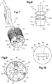
- the Figure 1 shows in rear perspective a key 10 having a rod 12 of cylindrical symmetry around an axis of revolution A and extending between a first end 14 provided with an operating member 16, and a second end 18 equipped with a bit and more precisely in the case of a double bit 20.
- the rod 12 extends to a free end 22 having a diametrical tongue 24.
- the double bit 20 has two diametrically opposed plates 26, 28 and notched symmetrically and at specific depths to perform encoding. It will be observed that the two plates 26, 28 extend in a mean plane Pm, and that the tongue 24 extends substantially perpendicular to the average plane Pm defined by these plates 26, 28. Also, the tongue 24 defines off-center peripheral stops The function of which will be explained later in the description. It also defines two axial bearing shoulders 32, 34.
- the Figure 2 shows a lock control assembly comprising a cylinder 36 inside which is introduced the key 10 shown on the Figure 1 .
- the cylinder 36 has an inlet slit 38 formed in an inlet flange 40 and through which the double bit 20 has been introduced.
- the cylinder 36 has a cylindrical protective casing 42 which it does not have on the Figure 3 .
- the cylinder 36 comprises, opposite the inlet flange 40, an outlet flange 44. Also, the cylinder 36 comprises, between the two flanges, a set of coded washers 46, which washers define a conditioned passage path 47 of the double bit 20. This set of coded washers 46 allows or not the axial engagement of the double bit 20 of the key 10 after rotation beyond the outlet flange 44 allowing the movement of a set of keys 48 located opposite a face rear 49 of the output flange 44 as will be explained below next to the Figure 5 .
- the cylinder 36 also has a split rear plate 45 located behind the set of keys 48.
- the set of key 48 comprises a main key 52 in a position spaced from this exit slot 50.
- the key 52 is mounted slidingly against the rear face 49 of the outlet flange 44 and extends substantially diametrically between a widened free end 54 of a thickened plate 56 and an opposite end 58.
- the output flange 44 has a main peripheral notch 60 inside which extends, in an axial direction of the cylinder 36, a main control shaft 62. The latter is secured at one of its ends, the opposite end 58 back of the key 52 and it extends the opposite to a position halfway about between the two flanges 40, 44.
- the main control shaft 62 comprises a main lever 64 having a first portion 66 which extends substantially perpendicular to the main control axis 62 and a second free portion 68, which extends back from the first portion 66, and to the conditioned passageway 47.
- the main lever 64 is retained in a position spaced from the path 47 through the double bit 20 of the key 10 which has been rotated 90 ° relative to its angular position during its introduction through the inlet slot 38 of the inlet flange 40.
- the cylinder 36 has a second secondary key 70 having a free hook end 72 and an opposite end 74 integral with a secondary axis 76 extending axially.
- the outlet flange 44 has a secondary peripheral notch 78 receiving the secondary axis 76.
- the latter also comprises a secondary lever 80.
- the secondary key 70 is in sliding abutment against the opposite end 58 back of the main key 52 and its free hook end 72 is abutting against an edge 82 of the thickened plate 56 of the main key 52.
- the secondary key 70 is kept away from the output slot 50 of the output plate 44 it releases.
- a cotter key 84 is also kept away from the exit slot 50 by the main key 52.
- the keyway 194 has a control pin 86 resting in a third slot 88 and which 'extends axially. It is also equipped with a lever (not shown in FIG.
- the keys 52, 70 and 84 are in this position illustrated on the Figure 5 , spaced from the exit slot 50 when the bit 20 has been introduced inside the passageway 47 and has been rotated 90 °. Such a position of the keys 52, 70 and 84 remains when the bit was then driven in translation through the outlet slot 50 beyond the set of keys 48 to actuate a lock mechanism not shown.
- the main lever 64 pivots and is driven towards the conditioned passageway 47. Therefore, the main key 52 also pivots around main control shaft 62 and closes the exit slot 50 of the outlet flange 44.
- the free hook end 72 of the secondary key 70 escapes the edge 82 of the thickened plate 56 and rotates in turn towards the exit slot 50 as illustrated on the Figure 4 , while coming to hang the plate in excess thickness 56. It thus blocks in rotation the main key 52.
- the kickstand key 84 pivots towards the exit slot 50 and comes to form a crutch against the main key 52 to block it also in pivoting .
- FIG. 10 We will first refer to the Figure 10 to describe the rear face 49 of the outlet flange 44.
- the exit slot 50 which extends diametrically. It will be observed that it presents an identical section, the game functional near, the section of the double bit 20 and the shank 12 of the key 10. It has a substantially rectangular longitudinal shape with two median widenings 90, 92 in circular segment.
- the upper median enlargement 90 is opposite to the lower median enlargement 92 and a radial housing 94 formed in the thickness of the outlet flange 44 opens substantially perpendicularly to the exit slot 50, in the upper enlargement 90 and, at the opposite, in the periphery of the outlet flange 44.
- This radial housing 94 has two opposite shoulders 96, 98 whose function will be explained below.
- the radial housing 94 is adapted to receive a movable flap 100 as shown in FIG. Figure 8 .
- the movable flap 100 has a front portion 102 and the opposite a posterior portion 104.
- the posterior portion 104 is then connected to two tangential elliptical rings 106, 108 and the last 108, is provided with a tail 110.
- the flap mobile 100, the two elliptical rings 106, 108 and the tail 110 are molded together in one piece 111 in a polymeric material, for example polyethylene. Therefore, the two elliptical rings 106, 108 are elastically deformable along the axis of symmetry D of said single piece. It will also be observed that the front portion 102 and the rear portion 104 of the movable flap 100 are separated from each other by two opposite bearing shoulders 112, 114.
- the piece 111 represented on the Figure 8 is adapted to be inserted in the radial housing 94, the front portion 102 to the outlet slot 50 and the tail 110 to the periphery of the outlet flange 44.
- the front portion 102 of the flap 100 extends into a portion of the exit slot 50 and more precisely, in the portion corresponding to the upper median widening 90. Therefore, thanks to the flap mobile 100, the double bit 20 of the key 10 can not be driven through the exit slot 58, even though it would have crossed the filter of the set of coded washers 46 because, the free end 22 of the rod 12 of section cylindrical circular base, would abut against him, if however this free end 22 was not provided with the diametral tongue 24.
- the diametral tongue 24 allows to retract the movable flap 100.
- the double bit 20 of the key 10 has been inserted in translation inside the conditioned passageway 47 along the axis of the cylinder C which is then coincidental with the axis of revolution A of the key, and this until the diametral tongue 24 comes to engage under the front portion 102 of the movable flap 100.
- the diametrical tongue 24 thus extends in a direction parallel to the mean plane defined by the exit slot 50.
- the front portion 102 of the movable flap 100 has been retracted into the radial housing 94, while the two elliptical rings 106, 108 have elastically compressed and deformed, the tail 110 bearing against the inside of the cylindrical protective casing 42.
- the diametral tongue 24 thus maintains the movable flap 100 in the retracted position, while the double bit 20 extends opposite the exit slot 50.
- the key 10 can be depressed even further. in order to carry the double bit 20 through the exit slot 50 and then out of the rear of the outlet flange 44 and the set of keys 48.
- the rod 12 is driven in friction against the front portion 102 of the movable flap 100 which remains retracted into the radial housing 94.
Landscapes
- Lock And Its Accessories (AREA)
- Preventing Unauthorised Actuation Of Valves (AREA)
- Connector Housings Or Holding Contact Members (AREA)
Abstract
L'invention concerne un ensemble de commande de verrouillage comprenant : un flasque de sortie (44) muni d'une fente de sortie (50) ; un jeu de rondelles (46) définissant un chemin de passage (47) ; un jeu de clavettes (48) en regard de ladite fente de sortie (50); une clé (10) comportant un panneton (20) terminé par une extrémité libre (22), et adapté à être engagé à l'intérieur du chemin de passage (47) pour coopérer avec lesdites rondelles (46) et avec lesdites clavettes (52, 70, 84) pour les écarter de ladite fente de sortie (50). Ledit flasque de sortie (44) comprend en outre un volet mobile (100) obturant une portion (90) de ladite fente de sortie (50). Et ladite extrémité libre (22) présente une butée excentrée (30) apte à être engagée à travers une autre portion de fente pour pouvoir écarter ledit volet mobile (100) de ladite fente de sortie (50).

Description
La présente invention se rapporte à un ensemble de commande de verrouillage à clé adapté à autoriser le passage d'une clé pour permettre ensuite d'actionner une serrure en entraînant la clé en rotation.The present invention relates to a key lock control assembly adapted to allow the passage of a key to then allow to actuate a lock by driving the key in rotation.
Des ensembles de commande de verrouillage connus comporte un cylindre présentant d'une part un flasque d'entrée dans lequel est ménagée une fente d'entrée et un flasque de sortie opposé dans lequel est ménagée une fente de sortie décalée angulairement d'environ 90° par rapport à la fente d'entrée. Le cylindre contient un jeu de rondelles empilées entre les flasques d'entrée et de sortie pour définir un chemin de passage conditionné de ladite clé entre ladite fente d'entrée et ladite fente de sortie. Le chemin de passage défini par les rondelles est conditionné en ce qu'il autorise ou non la rotation du panneton à travers le jeu de rondelles d'un angle voisin de 90°.Known locking control assemblies comprise a cylinder having on the one hand an inlet flange in which is provided an inlet slit and an opposite outlet flange in which is provided an exit slot angularly offset by approximately 90 °. compared to the entrance slot. The cylinder contains a set of washers stacked between the inlet and outlet flanges to define a conditioned path of passage of said key between said inlet slot and said exit slot. The passage path defined by the washers is conditioned in that it authorizes or not the rotation of the bit through the set of washers of an angle close to 90 °.
Les rondelles présentent des portions étendues radialement en saillie vers le centre du chemin de passage. Aussi, la clé dont le panneton présente des entailles radiales pour la coder, est autorisée à être entraînée en rotation à travers le jeu de rondelles si les entailles du panneton et les portions en saillie des rondelles coïncident respectivement.The washers have radially extended portions projecting towards the center of the passageway. Also, the key whose bit has radial notches to code it, is allowed to be rotated through the set of washers if the notches of the bit and the projecting portions of the rings coincide respectively.
En outre, le cylindre comporte un jeu de trois clavettes commandables obturant la fente de sortie. Chacune des clavettes du jeu comprend, un axe de commande s'étendant axialement vers ledit flasque d'entrée et un levier solidaire dudit axe de commande. Le levier s'étend radialement vers le chemin de passage conditionné pour pouvoir coopérer avec le panneton de la clé. Ainsi, si la rotation du panneton et de la clé est autorisée, le panneton vient entraîner séquentiellement les leviers, et partant les axes de commande des clavettes, lesquelles libèrent alors la fente de sortie. Partant, le panneton peut être ensuite enfoncé à travers la fente de sortie au-delà du flasque de manière à pouvoir actionner un mécanisme de serrure situé en arrière du flasque de sortie.In addition, the cylinder has a set of three controllable keys closing the exit slot. Each of the keys of the set comprises a control pin extending axially towards said inlet flange and a lever integral with said control pin. The lever extends radially towards the conditioned passage way to be able to cooperate with the bit of the key. Thus, if the rotation of the bit and the key is allowed, the bit sequentially drives the levers, and thus the control axes of the keys, which then release the exit slot. Therefore, the bit can then be pushed through the exit slot beyond the flange so as to actuate a lock mechanism located behind the outlet flange.
On pourra notamment se référer au document
Aussi, un problème qui se pose et que vise à résoudre la présente invention est notamment de fournir un ensemble de commande de verrouillage à clé qui soit plus malaisé à crocheter. En outre, la présente invention vise à fournir un ensemble de commande de verrouillage à clé économique.Also, a problem that arises and that aims to solve the present invention is in particular to provide a key lock control assembly that is more difficult to crochet. In addition, the present invention aims to provide an economic key lock control assembly.
Dans ce but, il est proposé un ensemble de commande de verrouillage à clé comprenant : un flasque d'entrée présentant une fente d'entrée et un flasque de sortie opposé présentant une fente de sortie ; un jeu de rondelles codées empilées entre lesdits flasques d'entrée et de sortie pour définir un chemin de passage entre lesdites fentes ; un jeu de clavettes commandables s'étendant en regard de ladite fente de sortie, les clavettes dudit jeu comprenant respectivement un axe de commande s'étendant axialement le long dudit chemin de passage ; une clé comportant un panneton codé terminé par une extrémité libre, ledit panneton étant adapté à être engagé à l'intérieur dudit chemin de passage pour coopérer avec lesdites rondelles codées et avec lesdits axes de commande lorsque ladite clé est entraînée en rotation de manière à écarter lesdites clavettes de ladite fente de sortie. Ledit flasque de sortie comprend en outre un volet mobile pour obturer une portion de ladite fente de sortie, tandis qu'une autre portion de ladite fente de sortie est libre ; et ladite extrémité libre présente une butée excentrée apte à être engagée à travers ladite autre portion pour pouvoir écarter ledit volet mobile de ladite fente de sortie lorsque ladite clé est entraînée en rotation pour pouvoir engager axialement ledit panneton à travers ladite fente de sortie.For this purpose, there is provided a key lock control assembly comprising: an input flange having an input slot and an opposite output flange having an output slot; a set of coded washers stacked between said input and output flanges to define a path of passage between said slots; a set of controllable keys extending opposite said exit slot, the keys of said set respectively comprising a control axis extending axially along said passage path; a key comprising a coded bit terminated by a free end, said bit being adapted to be engaged within said passageway to cooperate with said coded washers and with said control pins when said key is rotated so as to move away said keys of said exit slot. Said output flange further comprises a movable flap for closing a portion of said output slot, while another portion of said output slot is free; and said free end has an eccentric abutment adapted to be engaged through said other portion to be able to move said movable flap away from said exit slot when said key is rotated in order to be able to axially engage said bit through said exit slot.
Ainsi, une caractéristique de l'invention réside dans la mise en oeuvre du volet mobile grâce auquel, l'introduction du panneton codé à travers la fente de sortie est impossible, quand bien même le panneton codé correspondrait à l'encodage des rondelles empilées, si l'extrémité libre du panneton n'est pas munie de la butée excentrée. De la sorte, quand bien même l'encodage du panneton serait connu d'un tiers, sa reproduction ne permettrait pas au tiers d'utiliser la clé ainsi réalisée pour qu'elle puisse être engagée à travers la fente de sortie pour commander la serrure située au-delà. Grâce au volet mobile et à la clé associée, on diminue plus encore les risques d'effraction de l'ensemble de commande de verrouillage. En revanche, lorsque la clé associée à l'ensemble de commande de verrouillage est mise en oeuvre, la butée excentrée engagée à travers la fente dans ladite autre portion peut alors venir en butée contre le volet mobile de manière à ce qu'il se rétracte et libère ainsi totalement la fente. Puisque les clavettes ont déjà libéré cette même fente de sortie, le panneton peut alors être entraîné axialement à travers la fente et au-delà pour pouvoir ensuite agir sur le mécanisme de serrure lorsque la clé est une nouvelle fois entraînée en rotation. Ainsi, grâce au volet mobile, on vient obturer en partie la fente de sortie et par conséquent, on limite les possibilités de crochetage. Et grâce à la butée excentrée de l'extrémité libre de clé, on vient aisément écarter le volet mobile de la fente de sortie. De la sorte, l'ensemble de commande de verrouillage conforme à l'invention est malaisé à crocheter et de surcroît, il peut être réalisé à un coût avantageux.Thus, a feature of the invention lies in the implementation of the movable flap with which, the introduction of the bit coded through the output slot is impossible, even if the bit coded correspond to the encoding stacked washers, if the free end of the bit is not provided with the eccentric stop. In this way, even if the encoding of the bit is known to a third party, its reproduction would not allow the third party to use the key thus produced so that it can be engaged through the exit slot to control the lock located beyond. Thanks to the movable flap and the associated key, it further reduces the risk of burglary of the lock control assembly. However, when the key associated with the locking control assembly is implemented, the eccentric abutment engaged through the slot in said other portion can then abut against the movable flap so that it retracts and thus completely releases the slot. Since the keys have already released the same exit slot, the bit can then be driven axially through the slot and beyond to then act on the lock mechanism when the key is once again rotated. Thus, thanks to the movable flap, it closes part of the exit slot and therefore, it limits the possibilities of picking. And thanks to the eccentric stop of the free end of the key, it is easy to move the movable flap of the exit slot. In this way, the lock control assembly according to the invention is difficult to crochet and moreover, it can be realized at an advantageous cost.
En outre, et selon une caractéristique de l'invention particulièrement avantageuse, ladite fente de sortie présente deux élargissements médians opposés en segment circulaire, l'un desdits élargissements formant ladite une portion de ladite fente. Ainsi, le volet mobile est adapté à venir s'étendre dans au moins un des deux élargissements de la fente de sortie pour bloquer le passage du panneton.In addition, and according to a feature of the invention particularly advantageous, said exit slot has two opposite median widening in circular segment, one of said enlargements forming said a portion of said slot. Thus, the movable flap is adapted to extend in at least one of the two enlargements of the exit slot to block the passage of the bit.
Préférentiellement, ledit flasque de sortie présente un logement radial débouchant dans ladite une portion de ladite fente pour recevoir ledit volet mobile. Le volet mobile est alors mobile en translation à l'intérieur du logement radial entre une position où il vient s'étendre dans ladite une portion de fente et une position où il est rétracté à l'intérieur du logement radial. Après que la butée excentrée à provoquer l'écartement du volet mobile et sa rétraction à l'intérieur du logement radial, le panneton est alors entraîné en translation à travers la fente de sortie, tandis que le volet mobile est en appui glissant contre ce même panneton comme on l'expliquera dans la suite de la description. De la sorte, il demeure dans le logement radial.Preferably, said outlet flange has a radial housing opening into said portion of said slot for receiving said movable flap. The movable flap is then movable in translation inside the radial housing between a position where it extends into said slot portion and a position where it is retracted into the radial housing. After the eccentric abutment to cause the separation of the movable flap and its retraction inside the radial housing, the bit is then driven in translation through the exit slot, while the movable flap is in sliding contact against the same. bit as will be explained in the following description. In this way, it remains in the radial housing.
Aussi, ledit logement radial présente avantageusement un épaulement pour retenir ledit volet mobile dans une position d'obturation de ladite une portion de fente de sortie. De la sorte, le volet mobile demeure prisonnier du logement radial qui le guide en translation. Aussi, sa course est limitée entre une position où il obture totalement ladite une portion de fente et une position où il en est écarté totalement.Also, said radial housing advantageously has a shoulder for retaining said movable flap in a closed position of said outlet slot portion. In this way, the movable flap remains trapped in the radial housing which guides it in translation. Also, its stroke is limited between a position where it completely closes said slot portion and a position where it is totally removed.
Selon un mode de mise en oeuvre de l'invention particulièrement avantageux, ledit flasque de sortie comprend un organe élastique pour maintenir ledit volet mobile dans une position d'obturation de ladite une portion de fente de sortie. Ainsi, l'organe élastique vient rappeler le volet mobile vers une position où il est en butée contre l'épaulement du logement radial. Autrement dit, dès que le panneton est retiré de la fente de sortie, le volet mobile reprend sa position où il obture la portion de fente.According to a particularly advantageous embodiment of the invention, said outlet flange comprises an elastic member for holding said movable flap in a closed position of said outlet slot portion. Thus, the elastic member remembers the movable flap to a position where it abuts against the shoulder of the radial housing. In other words, as soon as the bit is withdrawn from the exit slot, the movable flap resumes its position where it closes the slot portion.
Selon un mode préféré de mise en oeuvre, ledit volet mobile et ledit organe élastique sont moulés ensemble d'une seule pièce en matériau polymère. De la sorte, l'organe élastique et le volet mobile sont réalisés à un coût avantageux. Par ailleurs, ledit organe élastique comprend avantageusement au moins deux anneaux tangents déformables. Ainsi, lorsque le matériau polymère est par exemple du polyéthylène ou encore du polyamide, on obtient à la fois un volet mobile relativement rigide et des anneaux déformables élastiquement.According to a preferred embodiment, said movable flap and said elastic member are molded together in one piece of polymeric material. In this way, the elastic member and the movable flap are made at an advantageous cost. Moreover, said elastic member advantageously comprises at least two deformable tangent rings. Thus, when the polymeric material is for example polyethylene or polyamide, one obtains both a relatively rigid movable flap and elastically deformable rings.
Selon une variante d'exécution de l'invention particulièrement avantageuse, ladite extrémité libre dudit panneton est de symétrie cylindrique à base circulaire et ladite butée excentrée est formée d'une languette diamétrale. Ainsi, en prévoyant deux élargissements médians opposés en segment circulaire permettant de former avec le complément de la fente de sortie une forme circulaire, l'extrémité du panneton coïncide parfaitement au jeu fonctionnel près avec la fente de sortie. Aussi, il est aisé de former une languette diamétrale à l'extrémité du panneton. De la sorte, et comme on l'expliquera plus en détail dans la suite de la description, la languette diamétrale présente une extrémité périphérique qui va pouvoir venir repousser le volet mobile lorsque la clé est entraînée en rotation.According to a particularly advantageous variant embodiment of the invention, said free end of said bit is of cylindrical symmetry with a circular base and said eccentric stop is formed of a diametrical tongue. Thus, by providing two opposite median widening in circular segment to form with the complement of the exit slot a circular shape, the end of the bit perfectly coincides with the functional clearance near the exit slot. Also, it is easy to form a diametrical tongue at the end of the bit. In this way, and as will be explained in more detail in the following description, the diametral tongue has a peripheral end that can come to push the movable flap when the key is rotated.
Préférentiellement, ladite clé comporte une tige présentant une extrémité de manoeuvre munie d'un anneau et une extrémité d'entraînement équipée de deux parties entaillées, symétriques l'une de l'autre par rapport à ladite tige, pour former ledit panneton. Les entailles des deux parties entaillées, et en particulier leur profondeur, détermine l'encodage du panneton. Grâce à la symétrie des deux parties entaillées, la clé peut être introduite à travers la fente d'entrée dans deux positions angulaires écartées de 180° l'une de l'autre.Preferably, said key comprises a rod having an operating end provided with a ring and a driving end equipped with two notched parts, symmetrical to each other with respect to said rod, to form said bit. The notches of the two notched parts, and in particular their depth, determines the encoding of the bit. Thanks to the symmetry of the two notched parts, the key can be introduced through the entrance slot in two angular positions spaced 180 ° from each other.
Aussi, ladite extrémité d'entraînement de la tige se termine par une extrémité libre formant ladite extrémité libre dudit panneton. Préférentiellement, la tige de la clé est donc de symétrie cylindrique la directrice circulaire. Toutefois, on prévoit de mettre en oeuvre une tige de clé présentant une section droite en croix.Also, said drive end of the rod ends with a free end forming said free end of said blade. Preferably, the stem of the key is therefore of cylindrical symmetry the circular director. However, it is expected to implement a key shaft having a cross section.
D'autres particularités et avantages de l'invention ressortiront à la lecture de la description faite ci-après d'un mode de réalisation particulier de l'invention, donné à titre indicatif mais non limitatif, en référence aux dessins annexés sur lesquels :
- la
Figure 1 est une vue schématique en perspective d'une clé pour un ensemble de commande de verrouillage conforme à l'invention ; - la
Figure 2 est une vue schématique en perspective de trois quarts avant d'un ensemble de commande de verrouillage selon l'invention ; - la
Figure 3 est une vue schématique partielle de dessus et de détail de l'ensemble de commande de verrouillage illustré sur laFigure 2 ; - la
Figure 4 est une vue schématique de trois quarts arrière de détail de l'ensemble de commande conforme à l'invention dans une première position ; - la
Figure 5 est une vue schématique de l'objet de laFigure 4 dans une seconde position ; - la
Figure 6 une vue schématique en perspective arrière de dessous de l'objet de laFigure 3 ; - la
Figure 7 est une vue schématique en perspective arrière de dessus de l'objet de laFigure 3 dans une première position ; - la
Figure 8 est une vue schématique de face d'un détail de laFigure 7 ; - la
Figure 9 est une vue schématique arrière des éléments représentés sur laFigure 7 dans une seconde position ; et, - la
Figure 10 est une vue schématique arrière d'un élément représenté sur laFigure 5 .
- the
Figure 1 is a schematic perspective view of a key for a lock control assembly according to the invention; - the
Figure 2 is a schematic perspective view of three quarters front of a lock control assembly according to the invention; - the
Figure 3 is a partial schematic top and detail view of the lock control assembly shown in FIG.Figure 2 ; - the
Figure 4 is a schematic view of three quarters rear detail of the control assembly according to the invention in a first position; - the
Figure 5 is a schematic view of the object of theFigure 4 in a second position; - the
Figure 6 a schematic rear perspective view from below of the object of theFigure 3 ; - the
Figure 7 is a schematic view in rear perspective from above of the object of theFigure 3 in a first position; - the
Figure 8 is a schematic front view of a detail of theFigure 7 ; - the
Figure 9 is a schematic rear view of the elements represented on theFigure 7 in a second position; and, - the
Figure 10 is a schematic rear view of an element represented on theFigure 5 .
La
La
On retrouve sur cette
On retrouve sur cette
Ainsi, le jeu de clavette 48 comprend une clavette principale 52 dans une position écartée de cette fente de sortie 50. La clavette 52 est montée en appui glissant contre la face arrière 49 du flasque de sortie 44 et elle s'étend sensiblement diamétralement entre une extrémité libre élargie 54 d'une platine en surépaisseur 56 et une extrémité opposée en retour 58. Le flasque de sortie 44 présente une encoche périphérique principale 60 à l'intérieur de laquelle vient s'étendre, selon une direction axial du cylindre 36, un axe de commande principal 62. Ce dernier est solidaire à l'une de ses extrémités, de l'extrémité opposée en retour 58 de la clavette 52 et il s'étend à l'opposé jusqu'à une position située à mi-distance environ entre les deux flasques 40, 44.Thus, the set of
L'axe de commande principal 62 comporte un levier principal 64 présentant une première portion 66 qui s'étend sensiblement perpendiculairement à l'axe de commande principal 62 et une seconde portion libre 68, qui s'étend en retour par rapport à la première portion 66, et vers le chemin de passage conditionné 47.The
Tel que présenté sur la
Au surplus, le cylindre 36 comporte une deuxième clavette secondaire 70 présentant une extrémité libre formant crochet 72 et une extrémité opposée 74 solidaire d'un axe secondaire 76 s'étendant axialement. Le flasque de sortie 44 présente une encoche périphérique secondaire 78 recevant l'axe secondaire 76. Ce dernier comporte également un levier secondaire 80. La clavette secondaire 70 est en appui glissant contre l'extrémité opposée en retour 58 de la clavette principale 52 et son extrémité libre formant crochet 72 est en butée contre un bord 82 de la platine en surépaisseur 56 de la clavette principale 52. Ainsi, la clavette secondaire 70 est-elle maintenue écartée de la fente de sortie 50 du flasque de sortie 44 qu'elle libère.In addition, the
À l'opposé de la clavette secondaire 70, une clavette béquille 84 est également maintenue écartée de la fente de sortie 50 par la clavette principale 52. La clavette béquille 84 présente un axe de commande 86 en appui dans une troisième encoche 88 et qui s'étend axialement. Il est également équipé d'un levier non représenté sur la Figure.Opposite the
Les clavettes 52, 70 et 84 sont dans cette position illustrée sur la
En revanche, lorsque le double panneton 20 est retiré du chemin de passage 47 après une rotation inverse de 90°, le levier principal 64 pivote et est entraîné vers le chemin de passage conditionné 47. Partant, la clavette principale 52 pivote également autour de l'axe de commande principal 62 et vient obturer la fente de sortie 50 du flasque de sortie 44. L'extrémité libre formant crochet 72 de la clavette secondaire 70 échappe alors au bord 82 de la platine en surépaisseur 56 et elle pivote à son tour vers la fente de sortie 50 comme illustré sur la
On se référera tout d'abord à la
Le logement radial 94 est adapté à recevoir un volet mobile 100 tel que représenté sur la
Ainsi, la pièce 111 représentée sur la
De la sorte, et comme l'illustre la
En effet, comme on va l'expliquer en regard des
Tout d'abord, comme illustre sur la
Ainsi, le double panneton 20 de la clé 10 a été inséré en translation à l'intérieur du chemin de passage conditionné 47 selon l'axe du cylindre C lequel est alors confondu avec l'axe de révolution A de la clé, et ce, jusqu'à ce que la languette diamétrale 24 vienne s'engager sous la partie frontale 102 du volet mobile 100. La languette diamétrale 24 s'étend ainsi dans une direction parallèle au plan moyen défini par la fente de sortie 50.Thus, the
À partir de cette situation telle que représentée sur la
Sur la
À l'inverse, lorsque le double panneton 20 est retiré, du cylindre 36, la partie frontale 102 du volet mobile 100 vient à échapper à la portée de la tige 12 et de son extrémité libre 22, et elle est alors entraînée à travers l'élargissement médian supérieur 90 grâce au relâchement des anneaux elliptiques 106, 108 lesquels reprennent leur forme originelle.Conversely, when the
Ainsi, on comprend qu'il est impossible d'insérer une clé dont le double panneton encodé correspondrait au jeu de rondelles codées, mais qui serait dépourvu de languette diamétrale.Thus, it is understood that it is impossible to insert a key whose double bit encoded would match the set of coded washers, but which would be devoid of diametrical tongue.
Claims (10)
et en ce que ladite extrémité libre (22) présente une butée excentrée (30) apte à être engagée à travers ladite autre portion pour pouvoir écarter ledit volet mobile (100) de ladite fente de sortie (50) lorsque ladite clé (10) est entraînée en rotation pour pouvoir engager axialement ledit panneton (20) à travers ladite fente de sortie (50).Key lock control assembly comprising:
and in that said free end (22) has an eccentric stop (30) adapted to be engaged through said other portion to be able to move said movable flap (100) away from said exit slot (50) when said key (10) is driven in rotation to axially engage said bit (20) through said outlet slot (50).
Applications Claiming Priority (1)
| Application Number | Priority Date | Filing Date | Title |
|---|---|---|---|
| FR1854165A FR3081177B1 (en) | 2018-05-18 | 2018-05-18 | KEY LOCK CONTROL ASSEMBLY |
Publications (2)
| Publication Number | Publication Date |
|---|---|
| EP3569799A1 true EP3569799A1 (en) | 2019-11-20 |
| EP3569799B1 EP3569799B1 (en) | 2023-11-22 |
Family
ID=63637972
Family Applications (1)
| Application Number | Title | Priority Date | Filing Date |
|---|---|---|---|
| EP19172466.5A Active EP3569799B1 (en) | 2018-05-18 | 2019-05-03 | Locking actuating assembly with a key |
Country Status (3)
| Country | Link |
|---|---|
| EP (1) | EP3569799B1 (en) |
| FR (1) | FR3081177B1 (en) |
| MA (1) | MA49926B1 (en) |
Citations (4)
| Publication number | Priority date | Publication date | Assignee | Title |
|---|---|---|---|---|
| DE524305C (en) * | 1929-06-02 | 1931-05-06 | Bauer A G | Cylinder lock |
| FR2734858A1 (en) | 1995-06-02 | 1996-12-06 | Deny | Secure cylinder lock opened by key |
| EP1681411A1 (en) | 2005-01-12 | 2006-07-19 | Deny Fontaine | Lock cylinder for key having a key bit which cross section is non-circular |
| EP3219881A1 (en) * | 2016-03-15 | 2017-09-20 | Deny Security | Lock cylinder with secure filter |
-
2018
- 2018-05-18 FR FR1854165A patent/FR3081177B1/en active Active
-
2019
- 2019-05-03 EP EP19172466.5A patent/EP3569799B1/en active Active
- 2019-05-03 MA MA49926A patent/MA49926B1/en unknown
Patent Citations (4)
| Publication number | Priority date | Publication date | Assignee | Title |
|---|---|---|---|---|
| DE524305C (en) * | 1929-06-02 | 1931-05-06 | Bauer A G | Cylinder lock |
| FR2734858A1 (en) | 1995-06-02 | 1996-12-06 | Deny | Secure cylinder lock opened by key |
| EP1681411A1 (en) | 2005-01-12 | 2006-07-19 | Deny Fontaine | Lock cylinder for key having a key bit which cross section is non-circular |
| EP3219881A1 (en) * | 2016-03-15 | 2017-09-20 | Deny Security | Lock cylinder with secure filter |
Also Published As
| Publication number | Publication date |
|---|---|
| MA49926B1 (en) | 2023-12-29 |
| FR3081177B1 (en) | 2020-05-29 |
| MA49926A (en) | 2020-06-24 |
| EP3569799B1 (en) | 2023-11-22 |
| FR3081177A1 (en) | 2019-11-22 |
Similar Documents
| Publication | Publication Date | Title |
|---|---|---|
| EP3473127B1 (en) | Fixing device for a bracelet | |
| FR3080155A1 (en) | TEMPORARY FIXING OF STRUCTURES | |
| EP2787579A1 (en) | Quick-attachment device for a two-part connector with quick disconnection | |
| CH713709A1 (en) | Bracelet link. | |
| EP2571113B1 (en) | Attachment and quick-connection device for a two-part connector | |
| EP1681411B1 (en) | Lock cylinder for key having a key bit which cross section is non-circular | |
| EP3569799B1 (en) | Locking actuating assembly with a key | |
| OA19293A (en) | Ensemble de commande de verrouillage à clé. | |
| EP3219881B1 (en) | Lock cylinder with secure filter | |
| EP3421925B1 (en) | Pivot link piece for a flying vehicle or for a system for a flying vehicle, in particular a missile | |
| EP2078806B1 (en) | Cylinder lock comprising disc tumbler assembly | |
| EP0451895B1 (en) | Roller driving device on a loom | |
| FR2802234A1 (en) | Safety lock cylinder comprises stator and rotor each with pin sliding in radial housing and anti-lock picking projecting stud on pin which limits sliding between rotor and stator | |
| FR2802233A1 (en) | Barrel lock with anti-vibration catch has sprung pins in rotor engaging stator and held by shoulder on stator against unauthorised operation | |
| EP3016563B1 (en) | Coupling device for suction duct | |
| EP0940529A1 (en) | Double plug security cylinder | |
| EP3999765B1 (en) | Compact and demountable fluid connection device | |
| FR2997722A1 (en) | Wheel for e.g. turbojet of aircraft, has disk with circumferential groove, and internal part, where rotation of part leads to elastic strain so as to generate spring force such that part is moved towards its deployed configuration | |
| FR2873285A1 (en) | DEVICE FOR ATTACHING A PILLAR SUPPORT OF PROSTHESIS TO A DENTAL IMPLANT | |
| OA18189A (en) | Secure filter lock cylinder | |
| FR3014976A1 (en) | FRICTION CLUTCH | |
| FR3033513A1 (en) | ARTICULATED BLADE KNIFE PROVIDED WITH IMPROVED BLOCKING VIROLE | |
| FR2875835A1 (en) | Lock for keyed electrical contactor, has circular support units maintained in several fixed positions with respect to stator and cooperating with stopper stub of key for authorizing removal of key in determined angular position | |
| FR2850999A1 (en) | Cylinder lock for door, has ring with stop flange co-operating with adjacent edge of opening of hatch fixed to stator whose external periphery is mounted with ring that is integrated to deformable legs | |
| EP2772602A1 (en) | Cylinder lock for construction key |
Legal Events
| Date | Code | Title | Description |
|---|---|---|---|
| PUAI | Public reference made under article 153(3) epc to a published international application that has entered the european phase |
Free format text: ORIGINAL CODE: 0009012 |
|
| STAA | Information on the status of an ep patent application or granted ep patent |
Free format text: STATUS: THE APPLICATION HAS BEEN PUBLISHED |
|
| AK | Designated contracting states |
Kind code of ref document: A1 Designated state(s): AL AT BE BG CH CY CZ DE DK EE ES FI FR GB GR HR HU IE IS IT LI LT LU LV MC MK MT NL NO PL PT RO RS SE SI SK SM TR |
|
| AX | Request for extension of the european patent |
Extension state: BA ME |
|
| STAA | Information on the status of an ep patent application or granted ep patent |
Free format text: STATUS: REQUEST FOR EXAMINATION WAS MADE |
|
| 17P | Request for examination filed |
Effective date: 20200520 |
|
| RAV | Requested validation state of the european patent: fee paid |
Extension state: TN Effective date: 20200520 Extension state: MA Effective date: 20200520 |
|
| RBV | Designated contracting states (corrected) |
Designated state(s): AL AT BE BG CH CY CZ DE DK EE ES FI FR GB GR HR HU IE IS IT LI LT LU LV MC MK MT NL NO PL PT RO RS SE SI SK SM TR |
|
| GRAP | Despatch of communication of intention to grant a patent |
Free format text: ORIGINAL CODE: EPIDOSNIGR1 |
|
| STAA | Information on the status of an ep patent application or granted ep patent |
Free format text: STATUS: GRANT OF PATENT IS INTENDED |
|
| INTG | Intention to grant announced |
Effective date: 20230704 |
|
| GRAS | Grant fee paid |
Free format text: ORIGINAL CODE: EPIDOSNIGR3 |
|
| GRAA | (expected) grant |
Free format text: ORIGINAL CODE: 0009210 |
|
| STAA | Information on the status of an ep patent application or granted ep patent |
Free format text: STATUS: THE PATENT HAS BEEN GRANTED |
|
| AK | Designated contracting states |
Kind code of ref document: B1 Designated state(s): AL AT BE BG CH CY CZ DE DK EE ES FI FR GB GR HR HU IE IS IT LI LT LU LV MC MK MT NL NO PL PT RO RS SE SI SK SM TR |
|
| REG | Reference to a national code |
Ref country code: GB Ref legal event code: FG4D Free format text: NOT ENGLISH |
|
| REG | Reference to a national code |
Ref country code: CH Ref legal event code: EP |
|
| REG | Reference to a national code |
Ref country code: DE Ref legal event code: R096 Ref document number: 602019041766 Country of ref document: DE |
|
| REG | Reference to a national code |
Ref country code: IE Ref legal event code: FG4D Free format text: LANGUAGE OF EP DOCUMENT: FRENCH |
|
| REG | Reference to a national code |
Ref country code: MA Ref legal event code: VAGR Ref document number: 49926 Country of ref document: MA Kind code of ref document: B1 |
|
| P01 | Opt-out of the competence of the unified patent court (upc) registered |
Effective date: 20231222 |
|
| REG | Reference to a national code |
Ref country code: LT Ref legal event code: MG9D |
|
| REG | Reference to a national code |
Ref country code: NL Ref legal event code: MP Effective date: 20231122 |
|
| PG25 | Lapsed in a contracting state [announced via postgrant information from national office to epo] |
Ref country code: GR Free format text: LAPSE BECAUSE OF FAILURE TO SUBMIT A TRANSLATION OF THE DESCRIPTION OR TO PAY THE FEE WITHIN THE PRESCRIBED TIME-LIMIT Effective date: 20240223 |
|
| PG25 | Lapsed in a contracting state [announced via postgrant information from national office to epo] |
Ref country code: IS Free format text: LAPSE BECAUSE OF FAILURE TO SUBMIT A TRANSLATION OF THE DESCRIPTION OR TO PAY THE FEE WITHIN THE PRESCRIBED TIME-LIMIT Effective date: 20240322 |
|
| PG25 | Lapsed in a contracting state [announced via postgrant information from national office to epo] |
Ref country code: LT Free format text: LAPSE BECAUSE OF FAILURE TO SUBMIT A TRANSLATION OF THE DESCRIPTION OR TO PAY THE FEE WITHIN THE PRESCRIBED TIME-LIMIT Effective date: 20231122 |
|
| REG | Reference to a national code |
Ref country code: AT Ref legal event code: MK05 Ref document number: 1633990 Country of ref document: AT Kind code of ref document: T Effective date: 20231122 |
|
| PG25 | Lapsed in a contracting state [announced via postgrant information from national office to epo] |
Ref country code: NL Free format text: LAPSE BECAUSE OF FAILURE TO SUBMIT A TRANSLATION OF THE DESCRIPTION OR TO PAY THE FEE WITHIN THE PRESCRIBED TIME-LIMIT Effective date: 20231122 |
|
| PG25 | Lapsed in a contracting state [announced via postgrant information from national office to epo] |
Ref country code: AT Free format text: LAPSE BECAUSE OF FAILURE TO SUBMIT A TRANSLATION OF THE DESCRIPTION OR TO PAY THE FEE WITHIN THE PRESCRIBED TIME-LIMIT Effective date: 20231122 |