EP3430233B1 - Unterwasserklemmenspannsystem - Google Patents
Unterwasserklemmenspannsystem Download PDFInfo
- Publication number
- EP3430233B1 EP3430233B1 EP16895645.6A EP16895645A EP3430233B1 EP 3430233 B1 EP3430233 B1 EP 3430233B1 EP 16895645 A EP16895645 A EP 16895645A EP 3430233 B1 EP3430233 B1 EP 3430233B1
- Authority
- EP
- European Patent Office
- Prior art keywords
- tensioning system
- tension
- subsea
- disposed
- housing
- Prior art date
- Legal status (The legal status is an assumption and is not a legal conclusion. Google has not performed a legal analysis and makes no representation as to the accuracy of the status listed.)
- Active
Links
Images
Classifications
-
- E—FIXED CONSTRUCTIONS
- E21—EARTH OR ROCK DRILLING; MINING
- E21B—EARTH OR ROCK DRILLING; OBTAINING OIL, GAS, WATER, SOLUBLE OR MELTABLE MATERIALS OR A SLURRY OF MINERALS FROM WELLS
- E21B43/00—Methods or apparatus for obtaining oil, gas, water, soluble or meltable materials or a slurry of minerals from wells
- E21B43/01—Methods or apparatus for obtaining oil, gas, water, soluble or meltable materials or a slurry of minerals from wells specially adapted for obtaining from underwater installations
- E21B43/013—Connecting a production flow line to an underwater well head
-
- F—MECHANICAL ENGINEERING; LIGHTING; HEATING; WEAPONS; BLASTING
- F16—ENGINEERING ELEMENTS AND UNITS; GENERAL MEASURES FOR PRODUCING AND MAINTAINING EFFECTIVE FUNCTIONING OF MACHINES OR INSTALLATIONS; THERMAL INSULATION IN GENERAL
- F16L—PIPES; JOINTS OR FITTINGS FOR PIPES; SUPPORTS FOR PIPES, CABLES OR PROTECTIVE TUBING; MEANS FOR THERMAL INSULATION IN GENERAL
- F16L1/00—Laying or reclaiming pipes; Repairing or joining pipes on or under water
- F16L1/26—Repairing or joining pipes on or under water
Definitions
- Tensioner systems are known in the art but hazards of using them include a buildup of unpredictably frictional loads created by thread and sliding frictions in the torqueing process. Standard torque systems lack predictability of gasket pre-load to input closure (tensioning and torqueing).
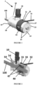
- Figs. 1 and 3 generally, as discussed below, there are two hubs (not shown in the figures), one on a side of subsea clamp tensioning system 1 towards an outboard device such as a tree, manifold, or PLET, and one on a connector.
- Subsea clamp tensioning system 1 holds the two hubs together, typically with a metal seal installed between them to prevent leakage.
- the hubs typically have multiple features for sealing, alignment, and interaction with subsea clamp tensioning system 1. As illustrated in the figures, a portion of tubular 100 may be threaded.
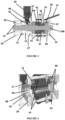
- Subsea clamp tensioning system 1 comprises housing 20; collar 30 dimensioned to fit about housing 20, where collar 30 comprises a plurality of offset channels 31; a set of adjusters 33 ( Fig. 3 ) corresponding to the plurality of offset channels 31; collar handle 32; a plurality of tension grips 40 ( Fig. 3 ) movingly disposed within interior void 21 ( Fig. 4 ), the plurality of tension grips 40 defining a tension grip channel 41 ( Fig. 3 ); subsea hydraulic motor 10; and nut runner 50 ( Fig.
- Housing 20 typically comprises interior void 21 ( Fig. 4 ) dimensioned to accept tubular 100 therethrough, first end 15, and second end 13 disposed opposite first end 15.
- One or more receivers 17 may be present at either first end 15 or second end 13, each receiver 17 dimensioned to receive a corresponding guide 16 and/or fastener 14.
- Tension grip stop 12 may be disposed proximate second housing end 13 and may further be disposed at least partially within interior void 21 ( Fig. 4 ). Tension grip stop 12 comprises a port dimensioned to allow a portion of tubular 100 to go through tension grip stop 12.
- each adjuster 33 typically comprises upper portion 34 configured to be larger in a dimension than its corresponding offset channel 31 ( Fig. 1 ) such that offset channel 31 prohibits travel of upper portion 34 into interior void 21 ( Fig. 4 ).
- Each adjuster 33 further typically comprises middle portion 35 connected to upper portion 34 which is dimensioned to travel into interior void 21 and lower portion 36 connected to middle portion 34, where lower portion 36 is engagable with its associated tension grip 40.
- Each adjuster also typically comprises one or more springs 37 disposed about a predetermined length of middle portion 35.
- Upper portion 34, middle portion 35, and lower portion 36 are contiguous.
- tension grip 40 may comprise any appropriate shape, it typically comprises a substantially trapezoidally shaped tension grip.
- Nut runner 50 may further comprise one or more gears 51, typically a bevel gear, which is operatively in communication with subsea hydraulic motor 10.
- Nut runner 50 typically comprises nut 54, operatively connected to subsea hydraulic motor 10, and preferably further comprises grooves dimensioned to cooperatively engage with corresponding threads in tubular 100.
- Nut 54 is typically rotationally disposed within nut runner 50.
- One or more seals 53 may disposed within housing interior void 21 and be operatively in occlusive communication with nut runner 50.
- tension grip housing 60 ( Fig. 3 ) is disposed at least partially within interior void 21 and each tension grip 40 movingly, e.g. pivotally at pivot 47, disposed within tension grip housing 60 at an end of tension grip 40 closest to first end 15.
- Interior void 21 may further comprise housing wall 27 disposed intermediate first end 15 and second end 13, where housing wall 27 comprises housing wall port 28 sufficiently sized to accept tubular 100 ( Fig. 1 ) therethrough.
- Tension grip housing 60 may then comprise first end 61 dimensioned to partially fit through housing wall port 28; second end 62 disposed opposite first end 61, where second end 62 defines a tension grip housing stop; and one or more stop springs 66 disposed between tension grip stop 12 and second end 62.
- subsea clamp tensioning system 1 is positioned about tubular 100, where subsea clamp tensioning system 1 is as described above.
- the plurality of tension grips 40 may be advanced against tubular 100 by pulling each of the adjusters 33 as opposed to turning them to create a desired tension.
- a nut spinning function of subsea clamp tensioning system 1 may be automated by having collar handle 32 utilize subsea hydraulic motor 10 to draw two clamp sections together around the hubs (not shown in the figures) after a set of connection tools (not shown in the figures) have brought the hubs face-to-face.
- the two subsea clamp tensioning systems 1 may be aligned during this process using receivers 17 and corresponding guides 16 and their opposing ends secured using tension grip stops 12.
- nut runner 50 is allowed to continue to spin nut 54 to mechanically lock subsea clamp tensioning system 1 such as by engaging and advancing threads on tubular 100.
- final clamp tension is created by making up tension via the built-in hydraulic piston load to create the desired gasket pre-load.
- collar handle 32 is typically allowed to snug adjusters 33 as subsea clamp tensioning system 1 is activated, e.g. by using adjusters 33 to advance one or more tension grips 40 against tubular 100.
- subsea clamp tensioning system 1 may be removed. It may also then be mounted onto a connector tool for retrieval to the surface.
Landscapes
- Life Sciences & Earth Sciences (AREA)
- Engineering & Computer Science (AREA)
- Geology (AREA)
- Mining & Mineral Resources (AREA)
- Physics & Mathematics (AREA)
- Environmental & Geological Engineering (AREA)
- Fluid Mechanics (AREA)
- General Life Sciences & Earth Sciences (AREA)
- Geochemistry & Mineralogy (AREA)
- Earth Drilling (AREA)
- Investigating Strength Of Materials By Application Of Mechanical Stress (AREA)
Claims (13)
- Unterwasser-Klemmenspannsystem, das Folgendes umfasst:a. ein Gehäuse (20), das Folgendes umfasst:i. einen Innenraum (21), der so bemessen ist, dass er ein dort hindurch verlaufendes Rohr (100) aufnehmen kann,ii. ein erstes Ende (15) undiii. ein zweites Ende (13), das dem ersten Ende gegenüber angeordnet ist,b. eine Schelle (30), die so bemessen ist, dass sie um das Gehäuse herum passt, wobei die Schelle mehrere versetzte Kanäle (31) umfasst,c. mehrere Spanngriffe (40), die beweglich in dem Innenraum angeordnet und so konfiguriert sind, dass sie zu dem Rohr (100) hin vorrücken und so für eine gewünschte Spannung sorgen, wobei die Spanngriffe einen Spanngriffkanal (41) definieren, wobei jeder Spanngriff einen Abschnitt des Spanngriffkanals definiert,d. einen Satz Einstellelemente (33) entsprechend den mehreren versetzten Kanälen, wobei jedes Einstellelement Folgendes umfasst:i. einen oberen Abschnitt (34), der so konfiguriert ist, dass eine Abmessung größer ist als bei dem versetzten Kanal, so dass der versetzte Kanal verhindert, dass sich der obere Abschnitt in den Innenraum hinein bewegt,ii. einen mittleren Abschnitt (35), der mit dem oberen Abschnitt verbunden und so bemessen ist, dass er sich durch den versetzten Kanal in den Innenraum hinein bewegt,iii. einen unteren Abschnitt (36), der mit dem mittleren Abschnitt verbunden ist, wobei der untere Abschnitt in den Spanngriff eingreifen kann, undiv. eine Feder (37), die um eine vorgegebene Länge des mittleren Abschnitts herum angeordnet ist,e. einen Unterwasser-Hydraulikmotor (10) undf. einen Drehschrauber (50), der in einem Abschnitt des Innenraums (21) angeordnet und so bemessen ist, dass er das Rohr aufnimmt und in Eingriff nimmt, wobei der Drehschrauber (50) mit dem Unterwasser-Hydraulikmotor (10) wirkverbunden ist, wobei der Drehschrauber (50) so bemessen ist, dass das Rohr durch ihn hindurch verlaufen kann.
- Unterwasser-Klemmenspannsystem nach Anspruch 1, das ferner einen Spanngriffanschlag (12) umfasst, der in der Nähe des zweiten Gehäuseendes (13) angeordnet ist.
- Unterwasser-Klemmenspannsystem nach Anspruch 2, wobei der Spanngriffanschlag (12) zumindest teilweise in dem Innenraum angeordnet ist.
- Unterwasser-Klemmenspannsystem nach Anspruch 1, wobei jeder Spanngriff (40) ferner einen im Wesentlichen trapezförmigen Spanngriff (40) umfasst.
- Unterwasser-Klemmenspannsystem nach Anspruch 1, wobei jeder der mehreren versetzten Kanäle (31) zu einem Spanngriff (40) der mehreren Spanngriffe (40) gehört.
- Unterwasser-Klemmenspannsystem nach Anspruch 1, das ferner ein Spanngriffgehäuse (60) umfasst, das zumindest teilweise in dem Innenraum (21) angeordnet ist, wobei jeder Spanngriff (40) an seinem dem ersten Ende (15) des Gehäuses (60) am nächsten gelegenen Ende drehbar in dem Spanngriffgehäuse (60) angebracht ist.
- Unterwasser-Klemmenspannsystem nach Anspruch 6, wobei:a. der Innenraum (21) ferner eine Gehäusewand (27) umfasst, die zwischen dem ersten Ende (15) und dem zweiten Ende (13) angeordnet ist, wobei die Gehäusewand eine Gehäusewandöffnung (28) umfasst, undb. das Spanngriffgehäuse (60) ferner Folgendes umfasst:i. ein erstes Ende (61), das so bemessen ist, dass es teilweise durch die Gehäusewandöffnung (28) passt,ii. ein zweites Ende (62), das dem ersten Ende gegenüber angeordnet ist, wobei das zweite Ende einen Spanngriffgehäuseanschlag definiert, undiii. eine Anschlagfeder (66), die zwischen dem Spanngriffanschlag (12) und dem Spanngriffgehäuseanschlag angeordnet ist.
- Unterwasser-Klemmenspannsystem nach Anspruch 7, wobei der Drehschrauber (50) ferner ein Zahnrad (51) umfasst, das mit dem Unterwasser-Hydraulikmotor (10) wirkverbunden ist.
- Unterwasser-Klemmenspannsystem nach Anspruch 8, wobei das Zahnrad ferner ein Kegelzahnrad umfasst.
- Unterwasser-Klemmenspannsystem nach Anspruch 8, das ferner eine Dichtung (53) umfasst, die in dem Gehäuseinnenraum (21) angeordnet und verschließend mit dem Drehschrauber (50) wirkverbunden ist.
- Unterwasser-Klemmenspannsystem nach Anspruch 1, wobei der Drehschrauber (50) ferner eine Mutter (54) umfasst, die mit dem Unterwasser-Hydraulikmotor wirkverbunden ist.
- Unterwasser-Klemmenspannsystem nach Anspruch 11, wobei:a. das Rohr Gewinde umfasst undb. die Mutter (54) ferner einen genuteten Drehschrauber (50) umfasst, der so bemessen ist, dass er in jeweilige Gewinde in dem Rohr eingreift.
- Unterwasser-Klemmenspannsystem nach Anspruch 11, wobei die Mutter (54) drehbar in dem Drehschrauber (50) angeordnet ist.
Priority Applications (1)
| Application Number | Priority Date | Filing Date | Title |
|---|---|---|---|
| EP24186022.0A EP4417850A3 (de) | 2016-03-19 | 2016-03-19 | Unterwasserklemmenspannsystem |
Applications Claiming Priority (1)
| Application Number | Priority Date | Filing Date | Title |
|---|---|---|---|
| PCT/US2016/023321 WO2017164834A1 (en) | 2016-03-19 | 2016-03-19 | Subsea clamp tensioning system |
Related Child Applications (1)
| Application Number | Title | Priority Date | Filing Date |
|---|---|---|---|
| EP24186022.0A Division EP4417850A3 (de) | 2016-03-19 | 2016-03-19 | Unterwasserklemmenspannsystem |
Publications (3)
| Publication Number | Publication Date |
|---|---|
| EP3430233A1 EP3430233A1 (de) | 2019-01-23 |
| EP3430233A4 EP3430233A4 (de) | 2019-11-06 |
| EP3430233B1 true EP3430233B1 (de) | 2024-07-24 |
Family
ID=59900723
Family Applications (2)
| Application Number | Title | Priority Date | Filing Date |
|---|---|---|---|
| EP24186022.0A Pending EP4417850A3 (de) | 2016-03-19 | 2016-03-19 | Unterwasserklemmenspannsystem |
| EP16895645.6A Active EP3430233B1 (de) | 2016-03-19 | 2016-03-19 | Unterwasserklemmenspannsystem |
Family Applications Before (1)
| Application Number | Title | Priority Date | Filing Date |
|---|---|---|---|
| EP24186022.0A Pending EP4417850A3 (de) | 2016-03-19 | 2016-03-19 | Unterwasserklemmenspannsystem |
Country Status (2)
| Country | Link |
|---|---|
| EP (2) | EP4417850A3 (de) |
| WO (1) | WO2017164834A1 (de) |
Families Citing this family (1)
| Publication number | Priority date | Publication date | Assignee | Title |
|---|---|---|---|---|
| CN108758126B (zh) * | 2018-06-16 | 2019-11-05 | 马鞍山小古精密机电科技有限公司 | 一种用于环保设备的废气处理输送装置 |
Family Cites Families (9)
| Publication number | Priority date | Publication date | Assignee | Title |
|---|---|---|---|---|
| US2265786A (en) * | 1940-01-05 | 1941-12-09 | Jr Harold T White | Apparatus for testing tension of wire ropes |
| US3231297A (en) * | 1961-07-31 | 1966-01-25 | Gray Tool Co | Expansible pipe joint clamp |
| US4989450A (en) * | 1989-08-01 | 1991-02-05 | Gse, Inc. | Cable tensiometer |
| US5471739A (en) * | 1995-01-27 | 1995-12-05 | Abb Vetco Gray Inc. | Remote clamp connector |
| US5671812A (en) * | 1995-05-25 | 1997-09-30 | Abb Vetco Gray Inc. | Hydraulic pressure assisted casing tensioning system |
| US6003548A (en) * | 1998-07-23 | 1999-12-21 | Hydril Company | Pressure vessel clamp connector |
| CA2265193C (en) * | 1999-03-11 | 2003-11-25 | Pawan R. Gupta | Device and method for testing the tension in stressed cables of concrete structure |
| NO319635B1 (no) * | 2002-08-19 | 2005-09-05 | Marine Direct Consultants Ltd | Anordning for sammenkopling av ror. |
| US7658131B1 (en) * | 2008-04-23 | 2010-02-09 | Titan Technologies International, Inc. | Subsea tensioner system |
-
2016
- 2016-03-19 EP EP24186022.0A patent/EP4417850A3/de active Pending
- 2016-03-19 WO PCT/US2016/023321 patent/WO2017164834A1/en not_active Ceased
- 2016-03-19 EP EP16895645.6A patent/EP3430233B1/de active Active
Also Published As
| Publication number | Publication date |
|---|---|
| WO2017164834A1 (en) | 2017-09-28 |
| EP4417850A3 (de) | 2024-11-06 |
| EP3430233A1 (de) | 2019-01-23 |
| EP3430233A4 (de) | 2019-11-06 |
| EP4417850A2 (de) | 2024-08-21 |
Similar Documents
| Publication | Publication Date | Title |
|---|---|---|
| DE69711863T2 (de) | Rohrverbindung | |
| DE102011078385A1 (de) | Trockenbauschrauber | |
| GB2505469A (en) | Outline Grapple connector assembly | |
| EP0101917A1 (de) | Geteiltes Werkzeug für die spanabhebende Bearbeitung | |
| DE102007016300A1 (de) | Elektrisch betätigter Werkzeugwechsler für Roboter | |
| US2218319A (en) | Adjustable extension | |
| EP2842670A3 (de) | Spannfutter | |
| US10107418B2 (en) | Subsea clamp tensioning system | |
| CA2704401A1 (en) | T-600 gas braking tool | |
| US20150330499A1 (en) | Method and Tools for Installation a Transmission Shift Cable End Bushing | |
| EP4417850A2 (de) | Unterwasserklemmenspannsystem | |
| DE10313739A1 (de) | Kupplungsbetätigungen | |
| DE102015114131A1 (de) | Ventildichtung-Ausbauwerkzeug | |
| CN101973006B (zh) | 一种仿生工具手 | |
| US3081812A (en) | Branch line connection tool | |
| DE102017100846B4 (de) | Vorrichtung zur Entnahme von Bodenproben aus einem Bohrloch | |
| EP2053298B1 (de) | Verteileranordnung | |
| DE102009058936A1 (de) | Vorrichtung zum druckdichten Verbinden der Zufuhrleitungen für Kunststoffkomponenten mit dem Innenkanal eines Gesteinsankers | |
| US11371637B2 (en) | Pipe fitting placement device | |
| US2372754A (en) | Adjustable cable splicing clamp | |
| EP3334549B1 (de) | Beweglicher rohrschneider mit schneidwerkzeug für rohre mit grossem durchmesser | |
| CN202062327U (zh) | 新型电缆无胶套管加工的专用拉套管工装 | |
| AU2012216478B2 (en) | Heat seal bar mounting apparatus of plastic bag making machine | |
| RU71364U1 (ru) | Запорно-пломбировочное устройство | |
| DE2113933A1 (de) | Werkzeug zur Anbringung von Einsaetzen |
Legal Events
| Date | Code | Title | Description |
|---|---|---|---|
| STAA | Information on the status of an ep patent application or granted ep patent |
Free format text: STATUS: THE INTERNATIONAL PUBLICATION HAS BEEN MADE |
|
| PUAI | Public reference made under article 153(3) epc to a published international application that has entered the european phase |
Free format text: ORIGINAL CODE: 0009012 |
|
| STAA | Information on the status of an ep patent application or granted ep patent |
Free format text: STATUS: REQUEST FOR EXAMINATION WAS MADE |
|
| 17P | Request for examination filed |
Effective date: 20180911 |
|
| AK | Designated contracting states |
Kind code of ref document: A1 Designated state(s): AL AT BE BG CH CY CZ DE DK EE ES FI FR GB GR HR HU IE IS IT LI LT LU LV MC MK MT NL NO PL PT RO RS SE SI SK SM TR |
|
| AX | Request for extension of the european patent |
Extension state: BA ME |
|
| DAV | Request for validation of the european patent (deleted) | ||
| DAX | Request for extension of the european patent (deleted) | ||
| A4 | Supplementary search report drawn up and despatched |
Effective date: 20191009 |
|
| RIC1 | Information provided on ipc code assigned before grant |
Ipc: E21B 33/038 20060101ALI20191002BHEP Ipc: E21B 33/043 20060101ALI20191002BHEP Ipc: F16L 35/00 20060101ALI20191002BHEP Ipc: E21B 43/013 20060101AFI20191002BHEP Ipc: F16L 19/00 20060101ALI20191002BHEP Ipc: E21B 17/01 20060101ALI20191002BHEP |
|
| STAA | Information on the status of an ep patent application or granted ep patent |
Free format text: STATUS: EXAMINATION IS IN PROGRESS |
|
| 17Q | First examination report despatched |
Effective date: 20230313 |
|
| P01 | Opt-out of the competence of the unified patent court (upc) registered |
Effective date: 20230526 |
|
| GRAP | Despatch of communication of intention to grant a patent |
Free format text: ORIGINAL CODE: EPIDOSNIGR1 |
|
| STAA | Information on the status of an ep patent application or granted ep patent |
Free format text: STATUS: GRANT OF PATENT IS INTENDED |
|
| INTG | Intention to grant announced |
Effective date: 20240305 |
|
| GRAS | Grant fee paid |
Free format text: ORIGINAL CODE: EPIDOSNIGR3 |
|
| GRAA | (expected) grant |
Free format text: ORIGINAL CODE: 0009210 |
|
| STAA | Information on the status of an ep patent application or granted ep patent |
Free format text: STATUS: THE PATENT HAS BEEN GRANTED |
|
| AK | Designated contracting states |
Kind code of ref document: B1 Designated state(s): AL AT BE BG CH CY CZ DE DK EE ES FI FR GB GR HR HU IE IS IT LI LT LU LV MC MK MT NL NO PL PT RO RS SE SI SK SM TR |
|
| RAP3 | Party data changed (applicant data changed or rights of an application transferred) |
Owner name: OCEANEERING INTERNATIONAL, INC. |
|
| REG | Reference to a national code |
Ref country code: GB Ref legal event code: FG4D |
|
| REG | Reference to a national code |
Ref country code: CH Ref legal event code: EP |
|
| REG | Reference to a national code |
Ref country code: DE Ref legal event code: R096 Ref document number: 602016088590 Country of ref document: DE |
|
| REG | Reference to a national code |
Ref country code: IE Ref legal event code: FG4D |
|
| REG | Reference to a national code |
Ref country code: LT Ref legal event code: MG9D |
|
| REG | Reference to a national code |
Ref country code: NL Ref legal event code: MP Effective date: 20240724 |
|
| PG25 | Lapsed in a contracting state [announced via postgrant information from national office to epo] |
Ref country code: PT Free format text: LAPSE BECAUSE OF FAILURE TO SUBMIT A TRANSLATION OF THE DESCRIPTION OR TO PAY THE FEE WITHIN THE PRESCRIBED TIME-LIMIT Effective date: 20241125 |
|
| REG | Reference to a national code |
Ref country code: AT Ref legal event code: MK05 Ref document number: 1706472 Country of ref document: AT Kind code of ref document: T Effective date: 20240724 |
|
| PG25 | Lapsed in a contracting state [announced via postgrant information from national office to epo] |
Ref country code: NL Free format text: LAPSE BECAUSE OF FAILURE TO SUBMIT A TRANSLATION OF THE DESCRIPTION OR TO PAY THE FEE WITHIN THE PRESCRIBED TIME-LIMIT Effective date: 20240724 |
|
| PG25 | Lapsed in a contracting state [announced via postgrant information from national office to epo] |
Ref country code: PT Free format text: LAPSE BECAUSE OF FAILURE TO SUBMIT A TRANSLATION OF THE DESCRIPTION OR TO PAY THE FEE WITHIN THE PRESCRIBED TIME-LIMIT Effective date: 20241125 Ref country code: NL Free format text: LAPSE BECAUSE OF FAILURE TO SUBMIT A TRANSLATION OF THE DESCRIPTION OR TO PAY THE FEE WITHIN THE PRESCRIBED TIME-LIMIT Effective date: 20240724 |
|
| PG25 | Lapsed in a contracting state [announced via postgrant information from national office to epo] |
Ref country code: FI Free format text: LAPSE BECAUSE OF FAILURE TO SUBMIT A TRANSLATION OF THE DESCRIPTION OR TO PAY THE FEE WITHIN THE PRESCRIBED TIME-LIMIT Effective date: 20240724 Ref country code: GR Free format text: LAPSE BECAUSE OF FAILURE TO SUBMIT A TRANSLATION OF THE DESCRIPTION OR TO PAY THE FEE WITHIN THE PRESCRIBED TIME-LIMIT Effective date: 20241025 Ref country code: PL Free format text: LAPSE BECAUSE OF FAILURE TO SUBMIT A TRANSLATION OF THE DESCRIPTION OR TO PAY THE FEE WITHIN THE PRESCRIBED TIME-LIMIT Effective date: 20240724 |
|
| PG25 | Lapsed in a contracting state [announced via postgrant information from national office to epo] |
Ref country code: BG Free format text: LAPSE BECAUSE OF FAILURE TO SUBMIT A TRANSLATION OF THE DESCRIPTION OR TO PAY THE FEE WITHIN THE PRESCRIBED TIME-LIMIT Effective date: 20240724 |
|
| PG25 | Lapsed in a contracting state [announced via postgrant information from national office to epo] |
Ref country code: LV Free format text: LAPSE BECAUSE OF FAILURE TO SUBMIT A TRANSLATION OF THE DESCRIPTION OR TO PAY THE FEE WITHIN THE PRESCRIBED TIME-LIMIT Effective date: 20240724 |
|
| PG25 | Lapsed in a contracting state [announced via postgrant information from national office to epo] |
Ref country code: AT Free format text: LAPSE BECAUSE OF FAILURE TO SUBMIT A TRANSLATION OF THE DESCRIPTION OR TO PAY THE FEE WITHIN THE PRESCRIBED TIME-LIMIT Effective date: 20240724 Ref country code: IS Free format text: LAPSE BECAUSE OF FAILURE TO SUBMIT A TRANSLATION OF THE DESCRIPTION OR TO PAY THE FEE WITHIN THE PRESCRIBED TIME-LIMIT Effective date: 20241124 |
|
| PG25 | Lapsed in a contracting state [announced via postgrant information from national office to epo] |
Ref country code: HR Free format text: LAPSE BECAUSE OF FAILURE TO SUBMIT A TRANSLATION OF THE DESCRIPTION OR TO PAY THE FEE WITHIN THE PRESCRIBED TIME-LIMIT Effective date: 20240724 |
|
| PG25 | Lapsed in a contracting state [announced via postgrant information from national office to epo] |
Ref country code: RS Free format text: LAPSE BECAUSE OF FAILURE TO SUBMIT A TRANSLATION OF THE DESCRIPTION OR TO PAY THE FEE WITHIN THE PRESCRIBED TIME-LIMIT Effective date: 20241024 Ref country code: ES Free format text: LAPSE BECAUSE OF FAILURE TO SUBMIT A TRANSLATION OF THE DESCRIPTION OR TO PAY THE FEE WITHIN THE PRESCRIBED TIME-LIMIT Effective date: 20240724 |
|
| PG25 | Lapsed in a contracting state [announced via postgrant information from national office to epo] |
Ref country code: RS Free format text: LAPSE BECAUSE OF FAILURE TO SUBMIT A TRANSLATION OF THE DESCRIPTION OR TO PAY THE FEE WITHIN THE PRESCRIBED TIME-LIMIT Effective date: 20241024 Ref country code: PL Free format text: LAPSE BECAUSE OF FAILURE TO SUBMIT A TRANSLATION OF THE DESCRIPTION OR TO PAY THE FEE WITHIN THE PRESCRIBED TIME-LIMIT Effective date: 20240724 Ref country code: LV Free format text: LAPSE BECAUSE OF FAILURE TO SUBMIT A TRANSLATION OF THE DESCRIPTION OR TO PAY THE FEE WITHIN THE PRESCRIBED TIME-LIMIT Effective date: 20240724 Ref country code: IS Free format text: LAPSE BECAUSE OF FAILURE TO SUBMIT A TRANSLATION OF THE DESCRIPTION OR TO PAY THE FEE WITHIN THE PRESCRIBED TIME-LIMIT Effective date: 20241124 Ref country code: HR Free format text: LAPSE BECAUSE OF FAILURE TO SUBMIT A TRANSLATION OF THE DESCRIPTION OR TO PAY THE FEE WITHIN THE PRESCRIBED TIME-LIMIT Effective date: 20240724 Ref country code: GR Free format text: LAPSE BECAUSE OF FAILURE TO SUBMIT A TRANSLATION OF THE DESCRIPTION OR TO PAY THE FEE WITHIN THE PRESCRIBED TIME-LIMIT Effective date: 20241025 Ref country code: FI Free format text: LAPSE BECAUSE OF FAILURE TO SUBMIT A TRANSLATION OF THE DESCRIPTION OR TO PAY THE FEE WITHIN THE PRESCRIBED TIME-LIMIT Effective date: 20240724 Ref country code: ES Free format text: LAPSE BECAUSE OF FAILURE TO SUBMIT A TRANSLATION OF THE DESCRIPTION OR TO PAY THE FEE WITHIN THE PRESCRIBED TIME-LIMIT Effective date: 20240724 Ref country code: BG Free format text: LAPSE BECAUSE OF FAILURE TO SUBMIT A TRANSLATION OF THE DESCRIPTION OR TO PAY THE FEE WITHIN THE PRESCRIBED TIME-LIMIT Effective date: 20240724 Ref country code: AT Free format text: LAPSE BECAUSE OF FAILURE TO SUBMIT A TRANSLATION OF THE DESCRIPTION OR TO PAY THE FEE WITHIN THE PRESCRIBED TIME-LIMIT Effective date: 20240724 |
|
| PG25 | Lapsed in a contracting state [announced via postgrant information from national office to epo] |
Ref country code: DK Free format text: LAPSE BECAUSE OF FAILURE TO SUBMIT A TRANSLATION OF THE DESCRIPTION OR TO PAY THE FEE WITHIN THE PRESCRIBED TIME-LIMIT Effective date: 20240724 Ref country code: RO Free format text: LAPSE BECAUSE OF FAILURE TO SUBMIT A TRANSLATION OF THE DESCRIPTION OR TO PAY THE FEE WITHIN THE PRESCRIBED TIME-LIMIT Effective date: 20240724 Ref country code: SM Free format text: LAPSE BECAUSE OF FAILURE TO SUBMIT A TRANSLATION OF THE DESCRIPTION OR TO PAY THE FEE WITHIN THE PRESCRIBED TIME-LIMIT Effective date: 20240724 |
|
| PG25 | Lapsed in a contracting state [announced via postgrant information from national office to epo] |
Ref country code: EE Free format text: LAPSE BECAUSE OF FAILURE TO SUBMIT A TRANSLATION OF THE DESCRIPTION OR TO PAY THE FEE WITHIN THE PRESCRIBED TIME-LIMIT Effective date: 20240724 |
|
| PG25 | Lapsed in a contracting state [announced via postgrant information from national office to epo] |
Ref country code: CZ Free format text: LAPSE BECAUSE OF FAILURE TO SUBMIT A TRANSLATION OF THE DESCRIPTION OR TO PAY THE FEE WITHIN THE PRESCRIBED TIME-LIMIT Effective date: 20240724 |
|
| REG | Reference to a national code |
Ref country code: DE Ref legal event code: R097 Ref document number: 602016088590 Country of ref document: DE |
|
| PG25 | Lapsed in a contracting state [announced via postgrant information from national office to epo] |
Ref country code: IT Free format text: LAPSE BECAUSE OF FAILURE TO SUBMIT A TRANSLATION OF THE DESCRIPTION OR TO PAY THE FEE WITHIN THE PRESCRIBED TIME-LIMIT Effective date: 20240724 Ref country code: SK Free format text: LAPSE BECAUSE OF FAILURE TO SUBMIT A TRANSLATION OF THE DESCRIPTION OR TO PAY THE FEE WITHIN THE PRESCRIBED TIME-LIMIT Effective date: 20240724 |
|
| PLBE | No opposition filed within time limit |
Free format text: ORIGINAL CODE: 0009261 |
|
| STAA | Information on the status of an ep patent application or granted ep patent |
Free format text: STATUS: NO OPPOSITION FILED WITHIN TIME LIMIT |
|
| 26N | No opposition filed |
Effective date: 20250425 |
|
| PGFP | Annual fee paid to national office [announced via postgrant information from national office to epo] |
Ref country code: GB Payment date: 20250522 Year of fee payment: 10 |
|
| PGFP | Annual fee paid to national office [announced via postgrant information from national office to epo] |
Ref country code: NO Payment date: 20250528 Year of fee payment: 10 |
|
| PG25 | Lapsed in a contracting state [announced via postgrant information from national office to epo] |
Ref country code: SE Free format text: LAPSE BECAUSE OF FAILURE TO SUBMIT A TRANSLATION OF THE DESCRIPTION OR TO PAY THE FEE WITHIN THE PRESCRIBED TIME-LIMIT Effective date: 20240724 |
|
| REG | Reference to a national code |
Ref country code: DE Ref legal event code: R119 Ref document number: 602016088590 Country of ref document: DE |
|
| PG25 | Lapsed in a contracting state [announced via postgrant information from national office to epo] |
Ref country code: MC Free format text: LAPSE BECAUSE OF FAILURE TO SUBMIT A TRANSLATION OF THE DESCRIPTION OR TO PAY THE FEE WITHIN THE PRESCRIBED TIME-LIMIT Effective date: 20240724 |
|
| REG | Reference to a national code |
Ref country code: CH Ref legal event code: H13 Free format text: ST27 STATUS EVENT CODE: U-0-0-H10-H13 (AS PROVIDED BY THE NATIONAL OFFICE) Effective date: 20251023 |
|
| PG25 | Lapsed in a contracting state [announced via postgrant information from national office to epo] |
Ref country code: LU Free format text: LAPSE BECAUSE OF NON-PAYMENT OF DUE FEES Effective date: 20250319 |
|
| REG | Reference to a national code |
Ref country code: BE Ref legal event code: MM Effective date: 20250331 |
|
| PG25 | Lapsed in a contracting state [announced via postgrant information from national office to epo] |
Ref country code: DE Free format text: LAPSE BECAUSE OF NON-PAYMENT OF DUE FEES Effective date: 20251001 |
|
| PG25 | Lapsed in a contracting state [announced via postgrant information from national office to epo] |
Ref country code: FR Free format text: LAPSE BECAUSE OF NON-PAYMENT OF DUE FEES Effective date: 20250331 |
|
| PG25 | Lapsed in a contracting state [announced via postgrant information from national office to epo] |
Ref country code: BE Free format text: LAPSE BECAUSE OF NON-PAYMENT OF DUE FEES Effective date: 20250331 |
|
| PG25 | Lapsed in a contracting state [announced via postgrant information from national office to epo] |
Ref country code: CH Free format text: LAPSE BECAUSE OF NON-PAYMENT OF DUE FEES Effective date: 20250331 |
|
| PG25 | Lapsed in a contracting state [announced via postgrant information from national office to epo] |
Ref country code: IE Free format text: LAPSE BECAUSE OF NON-PAYMENT OF DUE FEES Effective date: 20250319 |
|
| PG25 | Lapsed in a contracting state [announced via postgrant information from national office to epo] |
Ref country code: CY Free format text: LAPSE BECAUSE OF FAILURE TO SUBMIT A TRANSLATION OF THE DESCRIPTION OR TO PAY THE FEE WITHIN THE PRESCRIBED TIME-LIMIT Effective date: 20240724 |
|
| PG25 | Lapsed in a contracting state [announced via postgrant information from national office to epo] |
Ref country code: LT Free format text: LAPSE BECAUSE OF FAILURE TO SUBMIT A TRANSLATION OF THE DESCRIPTION OR TO PAY THE FEE WITHIN THE PRESCRIBED TIME-LIMIT Effective date: 20240724 |
|
| PG25 | Lapsed in a contracting state [announced via postgrant information from national office to epo] |
Ref country code: TR Free format text: LAPSE BECAUSE OF FAILURE TO SUBMIT A TRANSLATION OF THE DESCRIPTION OR TO PAY THE FEE WITHIN THE PRESCRIBED TIME-LIMIT Effective date: 20240724 |