EP3429885B1 - Dc-überstromschutzvorrichtung - Google Patents
Dc-überstromschutzvorrichtung Download PDFInfo
- Publication number
- EP3429885B1 EP3429885B1 EP17708793.9A EP17708793A EP3429885B1 EP 3429885 B1 EP3429885 B1 EP 3429885B1 EP 17708793 A EP17708793 A EP 17708793A EP 3429885 B1 EP3429885 B1 EP 3429885B1
- Authority
- EP
- European Patent Office
- Prior art keywords
- current
- bracket
- overcurrent
- current path
- ignition
- Prior art date
- Legal status (The legal status is an assumption and is not a legal conclusion. Google has not performed a legal analysis and makes no representation as to the accuracy of the status listed.)
- Active
Links
Images



Classifications
-
- H—ELECTRICITY
- H01—ELECTRIC ELEMENTS
- H01H—ELECTRIC SWITCHES; RELAYS; SELECTORS; EMERGENCY PROTECTIVE DEVICES
- H01H39/00—Switching devices actuated by an explosion produced within the device and initiated by an electric current
-
- B—PERFORMING OPERATIONS; TRANSPORTING
- B60—VEHICLES IN GENERAL
- B60L—PROPULSION OF ELECTRICALLY-PROPELLED VEHICLES; SUPPLYING ELECTRIC POWER FOR AUXILIARY EQUIPMENT OF ELECTRICALLY-PROPELLED VEHICLES; ELECTRODYNAMIC BRAKE SYSTEMS FOR VEHICLES IN GENERAL; MAGNETIC SUSPENSION OR LEVITATION FOR VEHICLES; MONITORING OPERATING VARIABLES OF ELECTRICALLY-PROPELLED VEHICLES; ELECTRIC SAFETY DEVICES FOR ELECTRICALLY-PROPELLED VEHICLES
- B60L3/00—Electric devices on electrically-propelled vehicles for safety purposes; Monitoring operating variables, e.g. speed, deceleration or energy consumption
- B60L3/0023—Detecting, eliminating, remedying or compensating for drive train abnormalities, e.g. failures within the drive train
- B60L3/0069—Detecting, eliminating, remedying or compensating for drive train abnormalities, e.g. failures within the drive train relating to the isolation, e.g. ground fault or leak current
-
- B—PERFORMING OPERATIONS; TRANSPORTING
- B60—VEHICLES IN GENERAL
- B60L—PROPULSION OF ELECTRICALLY-PROPELLED VEHICLES; SUPPLYING ELECTRIC POWER FOR AUXILIARY EQUIPMENT OF ELECTRICALLY-PROPELLED VEHICLES; ELECTRODYNAMIC BRAKE SYSTEMS FOR VEHICLES IN GENERAL; MAGNETIC SUSPENSION OR LEVITATION FOR VEHICLES; MONITORING OPERATING VARIABLES OF ELECTRICALLY-PROPELLED VEHICLES; ELECTRIC SAFETY DEVICES FOR ELECTRICALLY-PROPELLED VEHICLES
- B60L3/00—Electric devices on electrically-propelled vehicles for safety purposes; Monitoring operating variables, e.g. speed, deceleration or energy consumption
- B60L3/04—Cutting off the power supply under fault conditions
-
- H—ELECTRICITY
- H01—ELECTRIC ELEMENTS
- H01H—ELECTRIC SWITCHES; RELAYS; SELECTORS; EMERGENCY PROTECTIVE DEVICES
- H01H89/00—Combinations of two or more different basic types of electric switches, relays, selectors and emergency protective devices, not covered by any single one of the other main groups of this subclass
-
- H—ELECTRICITY
- H01—ELECTRIC ELEMENTS
- H01M—PROCESSES OR MEANS, e.g. BATTERIES, FOR THE DIRECT CONVERSION OF CHEMICAL ENERGY INTO ELECTRICAL ENERGY
- H01M50/00—Constructional details or processes of manufacture of the non-active parts of electrochemical cells other than fuel cells, e.g. hybrid cells
- H01M50/50—Current conducting connections for cells or batteries
- H01M50/572—Means for preventing undesired use or discharge
- H01M50/574—Devices or arrangements for the interruption of current
- H01M50/581—Devices or arrangements for the interruption of current in response to temperature
-
- H—ELECTRICITY
- H01—ELECTRIC ELEMENTS
- H01M—PROCESSES OR MEANS, e.g. BATTERIES, FOR THE DIRECT CONVERSION OF CHEMICAL ENERGY INTO ELECTRICAL ENERGY
- H01M50/00—Constructional details or processes of manufacture of the non-active parts of electrochemical cells other than fuel cells, e.g. hybrid cells
- H01M50/50—Current conducting connections for cells or batteries
- H01M50/572—Means for preventing undesired use or discharge
- H01M50/574—Devices or arrangements for the interruption of current
- H01M50/583—Devices or arrangements for the interruption of current in response to current, e.g. fuses
-
- H—ELECTRICITY
- H02—GENERATION; CONVERSION OR DISTRIBUTION OF ELECTRIC POWER
- H02H—EMERGENCY PROTECTIVE CIRCUIT ARRANGEMENTS
- H02H1/00—Details of emergency protective circuit arrangements
- H02H1/0007—Details of emergency protective circuit arrangements concerning the detecting means
-
- H—ELECTRICITY
- H02—GENERATION; CONVERSION OR DISTRIBUTION OF ELECTRIC POWER
- H02H—EMERGENCY PROTECTIVE CIRCUIT ARRANGEMENTS
- H02H3/00—Emergency protective circuit arrangements for automatic disconnection directly responsive to an undesired change from normal electric working condition with or without subsequent reconnection ; integrated protection
- H02H3/08—Emergency protective circuit arrangements for automatic disconnection directly responsive to an undesired change from normal electric working condition with or without subsequent reconnection ; integrated protection responsive to excess current
-
- H—ELECTRICITY
- H02—GENERATION; CONVERSION OR DISTRIBUTION OF ELECTRIC POWER
- H02H—EMERGENCY PROTECTIVE CIRCUIT ARRANGEMENTS
- H02H7/00—Emergency protective circuit arrangements specially adapted for specific types of electric machines or apparatus or for sectionalised protection of cable or line systems, and effecting automatic switching in the event of an undesired change from normal working conditions
- H02H7/16—Emergency protective circuit arrangements specially adapted for specific types of electric machines or apparatus or for sectionalised protection of cable or line systems, and effecting automatic switching in the event of an undesired change from normal working conditions for capacitors
-
- H—ELECTRICITY
- H02—GENERATION; CONVERSION OR DISTRIBUTION OF ELECTRIC POWER
- H02H—EMERGENCY PROTECTIVE CIRCUIT ARRANGEMENTS
- H02H7/00—Emergency protective circuit arrangements specially adapted for specific types of electric machines or apparatus or for sectionalised protection of cable or line systems, and effecting automatic switching in the event of an undesired change from normal working conditions
- H02H7/18—Emergency protective circuit arrangements specially adapted for specific types of electric machines or apparatus or for sectionalised protection of cable or line systems, and effecting automatic switching in the event of an undesired change from normal working conditions for batteries; for accumulators
-
- B—PERFORMING OPERATIONS; TRANSPORTING
- B60—VEHICLES IN GENERAL
- B60R—VEHICLES, VEHICLE FITTINGS, OR VEHICLE PARTS, NOT OTHERWISE PROVIDED FOR
- B60R16/00—Electric or fluid circuits specially adapted for vehicles and not otherwise provided for; Arrangement of elements of electric or fluid circuits specially adapted for vehicles and not otherwise provided for
- B60R16/02—Electric or fluid circuits specially adapted for vehicles and not otherwise provided for; Arrangement of elements of electric or fluid circuits specially adapted for vehicles and not otherwise provided for electric constitutive elements
- B60R16/03—Electric or fluid circuits specially adapted for vehicles and not otherwise provided for; Arrangement of elements of electric or fluid circuits specially adapted for vehicles and not otherwise provided for electric constitutive elements for supply of electrical power to vehicle subsystems or for
-
- H—ELECTRICITY
- H01—ELECTRIC ELEMENTS
- H01H—ELECTRIC SWITCHES; RELAYS; SELECTORS; EMERGENCY PROTECTIVE DEVICES
- H01H39/00—Switching devices actuated by an explosion produced within the device and initiated by an electric current
- H01H2039/008—Switching devices actuated by an explosion produced within the device and initiated by an electric current using the switch for a battery cutoff
-
- H—ELECTRICITY
- H01—ELECTRIC ELEMENTS
- H01H—ELECTRIC SWITCHES; RELAYS; SELECTORS; EMERGENCY PROTECTIVE DEVICES
- H01H39/00—Switching devices actuated by an explosion produced within the device and initiated by an electric current
- H01H39/004—Closing switches
-
- H—ELECTRICITY
- H01—ELECTRIC ELEMENTS
- H01M—PROCESSES OR MEANS, e.g. BATTERIES, FOR THE DIRECT CONVERSION OF CHEMICAL ENERGY INTO ELECTRICAL ENERGY
- H01M2200/00—Safety devices for primary or secondary batteries
-
- H—ELECTRICITY
- H01—ELECTRIC ELEMENTS
- H01M—PROCESSES OR MEANS, e.g. BATTERIES, FOR THE DIRECT CONVERSION OF CHEMICAL ENERGY INTO ELECTRICAL ENERGY
- H01M2200/00—Safety devices for primary or secondary batteries
- H01M2200/10—Temperature sensitive devices
- H01M2200/103—Fuse
-
- Y—GENERAL TAGGING OF NEW TECHNOLOGICAL DEVELOPMENTS; GENERAL TAGGING OF CROSS-SECTIONAL TECHNOLOGIES SPANNING OVER SEVERAL SECTIONS OF THE IPC; TECHNICAL SUBJECTS COVERED BY FORMER USPC CROSS-REFERENCE ART COLLECTIONS [XRACs] AND DIGESTS
- Y02—TECHNOLOGIES OR APPLICATIONS FOR MITIGATION OR ADAPTATION AGAINST CLIMATE CHANGE
- Y02E—REDUCTION OF GREENHOUSE GAS [GHG] EMISSIONS, RELATED TO ENERGY GENERATION, TRANSMISSION OR DISTRIBUTION
- Y02E60/00—Enabling technologies; Technologies with a potential or indirect contribution to GHG emissions mitigation
- Y02E60/10—Energy storage using batteries
Definitions
- the invention relates to a DC overcurrent protection device which comprises an ignition current-controlled irreversible high-current disconnection element, an overcurrent detection unit and control contacts for controlling the ignition current-controlled irreversible high-current disconnection element.
- a direct current also known as DC current
- DC current has to be limited to a maximum value in order to protect components against overcurrent in the event of an overload or short circuit.
- One example is the high-voltage electrical system in an electric or hybrid vehicle.
- two contactors and a fuse are usually installed in a high-voltage battery.
- the contactors separate the high-voltage battery from other components in the vehicle during normal operation and with smaller overload currents.
- the fuse takes over the disconnection in the event of high overload and short-circuit currents.
- the disadvantage of a conventional fuse is that it works according to the thermal principle and therefore requires a long current-dependent time to separate the current flow. As a result, if the currents are not too high, it may not be fast enough to protect the components in the vehicle against overload.
- An ignition element also known as a squib of the pyrotechnic shutdown element is ignited with a current signal and causes the high-current path to be cut off.
- the ignition signal is generated by monitoring electronics that measure the high current to be monitored and generate the ignition signal as soon as the current in the high-voltage network exceeds a maximum permissible value.
- This type of control of the pyrotechnic disconnection element has the following disadvantages:
- the current measuring circuit can be disturbed and the disturbance can cause false tripping or, conversely, non-tripping in the event of an overcurrent.
- the current measuring circuit with ignition electronics can have a complex structure and a high failure rate.
- the current measuring circuit always needs energy to function and thus increases the power consumption if it is not completely deactivated.
- the present invention is based on the object of reducing or avoiding the aforementioned disadvantages of the prior art.
- a DC overcurrent protection device is to be made available that is insensitive to interference, in particular electromagnetic interference, in order to avoid false tripping, does not cause permanent power consumption, has a low failure rate and reacts quickly to an overcurrent.
- the DC overcurrent protection device comprises an ignition current-controlled irreversible high-current disconnection element, an overcurrent detection unit, which is electrically connected in a high-current path in series with the ignition-current-controlled irreversible high-current disconnection element is switched, and control contacts for controlling the ignition current-controlled irreversible high-current switch-off element, which are arranged to be electrically connectable to one another.
- the overcurrent detection unit is designed such that when an overcurrent with a value equal to or greater than a predetermined current value flows in the high-current path, the control contacts due to a through the over current caused electromagnetic force are electrically connected to each other in such a way that an ignition current is transmitted to the ignition current-controlled irreversible high-current shutdown element, so that the ignition current-controlled irreversible high-current shutdown element is controlled into a shutdown state.
- the ignition current-controlled irreversible high-current shutdown element is a pyrotechnic shutdown element in one embodiment of the invention.
- a normal current is understood to mean a current with a value in the range from approx. 1000 amperes (hereinafter abbreviated as A) to approx. 1500 A.
- Currents greater than or equal to approx. 1500 A and less than approx. 3000 A can be reversibly switched with a contactor.
- the high-current path is understood to mean an electrical path that carries high currents with values of greater than or equal to approx. 1500 A to less than approx. 3000 A.
- such currents can occur in a high-voltage electrical system, which carries voltages between approximately 400 volts and approximately 800 volts, of a vehicle, in particular an electric, hybrid, or fuel cell vehicle.
- An overcurrent can be present above approx. 3000 A, so that in one embodiment the predetermined current value in the high-current path is approx. 3000 A, in particular 3000 A.
- the electromagnetic force caused by the overcurrent can be the Lorentz force, for example.
- the electromagnetic force is also understood to mean the force which, when an electrical current flows at each contact in the high-current path, causes at least partially opposing and touching high-current contact elements of the given contact to repel one another due to the current flow.
- This repulsive force occurs when the current flows in one of the two contact elements in a direction transverse to a contact surface of this contact element and in the other of the two contact elements in another direction transversely to a contact surface of the other contact element flows.
- the partial or completely opposing, but at least directionally changed, partial currents of the current flowing through the contact generate a repulsive force on the contact surfaces of the high-current contact elements of the given contact. This effect in DC contacts is also called electromagnetic levitation.
- the device according to the invention is not sensitive to interference, in particular to electromagnetic interference, which can impair a current measurement, but does not have enough energy to generate an electromagnetic force with an amount and for a period of time sufficient to electrically connect the control contacts to one another. This prevents the irreversible high-current disconnection element from being triggered incorrectly by electromagnetic interference of this type.
- the open control contacts which are separated from one another in the case of a high current below an overcurrent, are electrically connected to one another due to an electromagnetic force caused by the overcurrent, i.e. short-circuited or connected to an energy source for generating the ignition current in order to transmit the ignition current to the ignition-current-controlled irreversible high-current shutdown element .
- the electrical energy required to trigger the transmission of the ignition current is therefore only taken from the high-current path when there is an overcurrent.
- the device according to the invention therefore has no permanent power consumption.
- Embodiments which are explained with reference to the following figures, for generating the electromagnetic force caused by the overcurrent for the electrical connection of the control contacts to one another can be implemented without the use of electronic components, so that a failure rate of the device is very low and reduced in comparison to conventional devices is. Due to the simple structure of the device according to the invention for using the overcurrent to transmit the ignition current to the irreversible high-current cut-off element, the device reacts very quickly and more quickly than conventional devices.
- the overcurrent detection unit comprises a holding element which is arranged between a wall section of the overcurrent detection unit and a permanent magnet which can be moved relative to the wall section, which is held with a holding force of the holding element in the direction of the wall section and to which a first control contact is attached.
- the high-current path is wound around the permanent magnet and the overcurrent detection unit is designed so that, when the overcurrent flows in the high-current path, the permanent magnet moves against the holding force of the holding element in such a way that the first control contact touches a second control contact that is stationary relative to the wall section.
- the first control contact is short-circuited with the second control contact, so that the ignition current is transmitted to the ignition current-controlled irreversible high-current disconnection element by an energy source connected to the second control contact.
- the structure for short-circuiting the control contacts is very simple and only comprises a winding of the high-current path, the permanent magnet and a holding element.
- This DC overcurrent protection device according to the invention is therefore very fail-safe, reliable and trips quickly in the event of an overcurrent. Energy is taken from the high-current path only when an overcurrent occurs, which is why the device consumes little current.
- the overcurrent detection unit is completely reversible, ie it can be reused without modification after an overcurrent has occurred, and is therefore reliable and requires little maintenance.
- a capacitor, a double-layer capacitor, a battery, a high-voltage battery itself that supplies the on-board network to be protected from an overcurrent, or the like, can be used as the energy source.
- a charging circuit can be implemented which recharges the energy source periodically or when it drops to a minimum energy value that is required for maintaining the operation of the energy source in order to compensate for self-discharge.
- control contacts are included in the overcurrent detection unit.
- the permanent magnet is led out of a housing of the overcurrent detection unit and the first and / or second control contact is / is arranged outside the overcurrent detection unit.
- the winding can be designed such that the high-current path comprises an inductance which comprises at least one loop.
- the overcurrent detection unit comprises a holding element which is arranged between a wall section of the overcurrent detection unit and a high-current-conducting bracket which is movable relative to the wall section and to which a first control contact is attached.
- the bracket is held with a holding force of the holding element in the direction of the wall section in such a way that a current flow in the high-current path is guided through the bracket and the bracket forms part of the high-current path.
- the overcurrent detection unit is designed so that when the overcurrent flows in the high-current path, the bracket moves against the holding force of the holding element in such a way that the first control contact touches a second control contact, which is stationary with respect to the wall section, whereby the first control contact with the second Control contact is short-circuited.
- an energy source connected to the second control contact transfers the ignition current to the ignition current-controlled irreversible high-current disconnection element.
- the first control contact can be separated from the bracket by an insulation element in the form of an insulation layer.
- the insulation element can be made of plastic or some other non-conductive material.
- the first control contact can be attached to a side of the bracket that is opposite a side of the bracket to which the holding element is attached.
- the structure for short-circuiting the control contacts can be even simpler than in the previous embodiments and only require the insertion of two contact points in the high-current path to form the bracket and the attachment of a retaining element to the bracket.
- the control contacts are included in the overcurrent detection unit.
- the first and / or the second control contact can be arranged outside the overcurrent detection unit.
- the overcurrent detection unit comprises a holding element which is arranged between a wall section of the overcurrent detection unit and a high-current-conducting bracket that is movable relative to the wall section.
- the bracket is held with a holding force of the holding element in the direction of the wall section in such a way that a current flow in the high-current path is guided through the bracket and the bracket forms part of the high-current path.
- a first control contact is in front of the part of the high-current path formed by the bracket and a second control contact is in each case after the part of the high-current path formed by the bracket connected to the high current path.
- the overcurrent detection unit is designed so that when the overcurrent flows in the high-current path, the bracket moves against the holding force of the holding element away from the part of the high-current path not formed by the bracket, that at at least one high-current contact point between the bracket and the not through the Stirrups formed part of the high-current path forms an arc that has a resistance that leads to a voltage drop across the first and second control contacts.
- the voltage and the resistance have the effect that the ignition current is transmitted to the ignition current-controlled irreversible high-current disconnection element.
- the arc that occurs when the bracket separates from the part of the high-current path not formed by the bracket in the event of an overcurrent is used as an energy source for generating the ignition current.
- An arc can occur at either end of the bracket.
- one end of the bracket can be rotatably and electrically conductively connected to the part of the high-current path that is not formed by the bracket.
- the control contacts are therefore not short-circuited, but are electrically connected to one another via a resistor which is formed by the arc.
- the control contacts connected to the part of the high-current path not formed by the bracket can be arranged in such a way that the bracket is connected between the control contacts. It is therefore possible to arrange the control contacts or one of the two control contacts inside or outside the overcurrent detection unit.
- the holding element can be designed as a fixed holder which breaks when the electromagnetic force generated by the overcurrent exceeds a predetermined value. In this way the holding element can be provided in a simple and inexpensive manner.
- the overcurrent detection unit comprises a holding element which is arranged between a wall section of the overcurrent detection unit and a high-current-conducting bracket that is movable relative to the wall section.
- the bracket is held with a holding force of the holding element in the direction of the wall section and a permanent magnet is attached to the bracket and guided in a winding that, when no control voltage from a voltage source is applied to the winding, a current flow in the high-current path through the bracket is avoided and the bracket does not form part of the high-current path.
- a first control contact is connected to the high-current path in front of the part of the high-current path formed by the bracket and a second control contact after the part of the high-current path formed by the bracket.
- a contactor which is connected to the voltage source, is connected between at least one of the first and second control contacts and the ignition current-controlled irreversible high-current disconnection element in such a way that, when no control voltage from the voltage source is applied to the winding and to the contactor, and the bracket is not part of the high-current path forms, an open circuit voltage applied across the first and second control contacts does not cause the ignition current to be transferred to the ignition current-controlled irreversible high-current shutdown element.
- the overcurrent detection unit is designed in such a way that when the overcurrent flows in the high-current path, the bracket moves away from the part of the high-current path that is not formed by the bracket in the direction of the holding force of the holding element, despite the control voltage of the voltage source applied to the winding and to the contactor an arc is formed at at least one high-current contact point between the bracket and the part of the high-current path that is not formed by the bracket.
- the arc has a resistance which leads to a voltage drop across the first and second control contacts. The voltage and the resistance have the effect that the ignition current is transmitted to the ignition current-controlled irreversible high-current disconnection element.
- the overcurrent detection unit forms a high-current contactor, the contactor preventing an open circuit voltage that is present across the bracket when the high-current contactor is open from leading to the ignition current being transmitted to the irreversible high-current disconnection element.
- This disconnection element therefore only triggers when the high-current contactor is closed for a current flow in the high-current path and an overcurrent occurs in such a way that an arc is formed between the bracket and the part of the high-current path that is not formed by the bracket, which is sufficient for the irreversible High-current disconnection element switches off the current flow in the high-current path.
- the overcurrent detection unit can reversibly disconnect or close the high-current path.
- the holding element can be designed as a spring.
- the DC overcurrent protection device according to the invention can in an advantageous embodiment be integrated in a housing and / or as a component.
- the DC overcurrent protection device according to the invention can also be integrated in a high-voltage electrical system for a vehicle, preferably for an electric or hybrid vehicle.
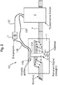
- FIG. 1 shows a schematic arrangement of a DC overcurrent protection device 100 with an ignition current-controlled irreversible high-current disconnection element 2, which is electrically connected in series in a high-current path 4 to an overcurrent detection unit 1.
- the ignition current-controlled irreversible high-current switch-off element 2 is designed as a pyrotechnic switch-off element and is electrically connected to a first ignition current transmission line 13.
- An energy source 3 for example a capacitor, double-layer capacitor, a battery or high-voltage battery of a high-voltage electrical system to be protected for an overcurrent, is connected to the pyrotechnic disconnection element via the ignition current transmission line 13.
- the energy source 3 can be connected to the pyrotechnic disconnection element 2 in such a way that an ignition current is transmitted from the energy source 3 to the pyrotechnic disconnection element in order to the pyrotechnic shutdown element 2 to control in a shutdown state. As soon as the shutdown state has occurred, a flow of current in the high-current path 4 is prevented by the pyrotechnic shutdown element 2.
- the control of the pyrotechnic shutdown element 2 in the shutdown state is irreversible, so that the pyrotechnic shutdown element 2 must be replaced after shutdown so that the DC overcurrent protection device continues to function.
- the function of the DC overcurrent protection device is to pass a normal high current, which is between approx. 1500 A and below approx. 3000 A, in the high current path 4 and to prevent a current flow in the high current path 4 from an overcurrent of approx. 3000 A. .
- the overcurrent detection unit 1 is designed such that, when an overcurrent flows in the high-current path 4, the control contacts 11 are short-circuited due to an electromagnetic force caused by the overcurrent in such a way that an ignition current is transmitted from the energy source 3 to the ignition-current-controlled irreversible high-current shutdown element 2, so that this shutdown element 2 is controlled in the shutdown state.
- FIG. 2 shows the structure of a DC overcurrent protection device 100 in a further embodiment with a completely reversible overcurrent detection unit 1, which can be used again without a change after the overcurrent has occurred in the high-current path 4.
- the overcurrent detection unit 1 comprises a winding in the form of an inductance, which in the simplest case, as in FIG Figure 2 shown, is formed by a conductor loop 12 of the high-current path 4.
- the conductor loop 12 is guided around a permanent magnet 8, which is connected at one end to a wall section of a housing of the overcurrent detection unit 1 via a retaining element 5 in the form of a retaining spring.
- the permanent magnet 8 is with a holding force of the holding element 5 in the direction of the wall section held (see arrow Ff in Fig.
- first control contact 11A which, in the case of a normal high current below the overcurrent in the high current path 4, is opposite a second control contact 11B, which is fixedly arranged opposite the wall section, and via a first control line 13A with the pyrotechnic shutdown element 2 is electrically connected.
- a magnetic field formed by the conductor loop 12 when a current flows through the high-current path 4 acts on the permanent magnet 8 and can move the permanent magnet 8.
- a current in the high current path 4 reaches or exceeds the value of the overcurrent, that is, from a normal high current to an overcurrent, there is an overcurrent which leads to a magnetic field formed by the conductor loop 12 that is high enough for the permanent magnet 8 to move moved against the holding force of the holding element 5 (see arrow Fi in Fig. 2 ) that the movable first control contact 11A touches the second stationary control contact 11B, whereby the first and second control contacts 11A, 11B are short-circuited.
- the energy source 3 connected to the second contact 11B via a second control line 13B is connected to the pyrotechnic disconnection element 2 via a second ignition current transmission line 13C in such a way that an ignition current is transmitted to the pyrotechnic disconnection element 2, in order to switch off the pyrotechnic switch-off element 2, which results in an interruption of a current flow in the high-current path 4.
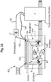
- FIG. 3A shows the structure of the DC overcurrent protection device 100 according to the invention with an irreversible overcurrent detection unit 1 at a normal high current below the overcurrent in a further embodiment according to FIG Figure 1 shown schematic arrangement.
- the overcurrent detection unit 1 comprises a holding element 5A that is arranged between a wall section of a housing of the overcurrent detection unit 1 and a high-current-conducting rail bracket 6 that is movable relative to the wall section and to which the first control contact 11A is attached.
- the first control contact 11A is electrically isolated from the bracket 6 by an insulation layer 7.
- the bracket 6 is held with a holding force of the holding element 5A in the direction of the wall section (see arrow Ff in Figure 3A ) that a current flow in the high-current path 4 with a normal high current is guided below the overcurrent through the bracket 6, so that the bracket 6 forms part of the high-current path 4.
- bracket 6 Ends of the bracket 6 form high-current contacts with sections 4A, 4B of the part of the high-current path 4 that is not formed by the bracket 6.
- the bracket 6 is pressed against the high-current contacts by the holding element 5A in the form of a retaining spring, so that when a current has a value which is smaller than the value of the overcurrent through which the high-current path 4 this current is passed through the bracket 6 as part of the high-current path 4.
- the first control contact 11A at a normal high current in the high current path 4 is spaced apart from a second control contact 11B, which is fixedly arranged opposite the wall section, the first control contact 11A being electrically connected to the pyrotechnic disconnection element 2 via a first control line 13A.
- the energy source 3 connected to the second contact 11B via a second control line 13B is connected to the pyrotechnic disconnection element 2 via the second ignition current transmission line 13C.
- an electromagnetic force arises at each high-current contact in the high-current path 4, which tries to pull the high-current contacts apart (see arrow Fi in Figure 3A ).
- Figure 3B shows the structure of the in Figure 3A DC overcurrent protection device 100 shown according to the invention in the event of an overcurrent. If an overcurrent flows in the high-current path 4, the bracket 6 is against the holding force of the holding element (see arrow Fi in Figure 3B ) moved in such a way that the first control contact 11A touches the second stationary control contact 11B, whereby the first control contact 11A and the second control contact 11B are short-circuited, so that the energy source 3 supplies an ignition current 15 to the pyrotechnic disconnection element 2, which is necessary for disconnection of the pyrotechnic switching element 2 transmits, which leads to a separation 16 of the high-current path 4.
- the high-current contacts at the sections 4A, 4B of the high-current path 4 pull apart and the bracket 6 moves against the holding force of the holding element 5A and closes the first and second control contacts 11A, 11B short.
- an arc 14 is formed on each of the high-current contacts.
- the arc 14 advantageously has a high resistance, which has the effect that the current flowing in the high-current path 4 is reduced. This simplifies the separation / prevention of the current / current flow in the high-current path 4 by the pyrotechnic shutdown element 2.
- the use of the arc 14 as a resistor for easier disconnection by the pyrotechnic disconnection element 2 is particularly advantageous in the case of very high short-circuit currents in the high-current path 4.
- the overcurrent detection unit 1 is permanently damaged by the arc 14, possibly combined with spark formation, so that the overcurrent detection unit 1 does not after the occurrence of an overcurrent can continue to functionally be used without repairing the damaged sections 4A, 4B of the high-current path 4 and the bracket 6.
- the DC overcurrent protection device 100 shown in the figure can be replaced by a fixed holder instead of the holding element 5A in the form of the holding spring, which holder breaks when the electromagnetic force exceeds the predetermined value for an overcurrent.
- FIG. 4 shows the structure of the DC overcurrent protection device 100 according to the invention in a further embodiment with a bracket 6 connected between control contacts 11C, 11D in the event of an overcurrent.
- High-current contacts are formed by the ends of the bracket 6 and sections 4A, 4B of the high-current path 4.
- the overcurrent detection unit 1 comprises a holding element 5B which is arranged between a wall section of a housing of the overcurrent detection unit 1 and the high-current-conducting bracket 6 which is movable relative to the wall section.
- the bracket 6 is with a holding force of the holding element 5B (see arrow Ff in Fig.
- the structure corresponds to that in Figure 4 overcurrent detection unit 1 shown the structure of the overcurrent detection unit 1, which in the Figures 3A , 3B is shown.
- the overcurrent detection unit 1 shown is in one direction of the current flow (see arrows within the high-current path 4, which point from the overcurrent detection unit 1 to the pyrotechnic disconnection element 2) of the high-current path 4, the first control contact 11C in front of the part of the high-current path 4 formed by the bracket to the section 4A of High current path 4 connected.
- the second control contact 11D is connected to the section 4B of the high-current path 4 after the part of the high-current path 4 formed by the bracket 6.
- the bracket 6 moves against the holding force of the holding element 5B away from the part of the high-current path 4 with the sections 4A, 4B that is not formed by the bracket (see arrow Fi in Fig. 4 ) that an arc 14 is formed at the high-current contact points between the bracket 6 and the sections 4A, 4B of the high-current path 4, which has a resistance that leads to a voltage drop across the first and second control contacts 11C, 11D.
- This voltage and the resistance of the arc 14 cause the ignition current 15, which is transmitted to the pyrotechnic disconnection element 2 to perform a separation 16 of the high-current path 4.
- DC overcurrent protection device 100 shown in contrast to that in FIG Figures 3A , 3B DC overprotection device 100 shown does not have an energy source 3 that is connected to the second control line 13B and the second ignition current transmission line 13C. Instead, the bracket 6 is connected between the first and second control contacts 11C, 11D in such a way that, in the event of an overcurrent, arcs 14 at the ends of the arc 6 and the sections 4A, 4B of the high-current path 4 cause a voltage and a resistance that are sufficient for the to generate the ignition current 15 required to separate the high-current path 4 and to transmit it to the pyrotechnic disconnection element 2.
- first and second control contacts 11C, 11D are electrically connected to the pyrotechnic disconnection element 2 via third and fourth control lines 13D, 13E, and in a further embodiment an indirect connection is alternatively possible, and connected to one another in a fixed manner to the high-current path 4, that the arc 14 or the voltage formed by the arc 14 at the high-current contacts at the ends of the bracket 6 forms the energy source for the ignition of the pyrotechnic shutdown element 2.
- FIG. 5 shows the structure of a further embodiment of the DC overcurrent protection device 100 according to the invention with a bracket 6 connected between first and second control contacts 11E, 11F and an overcurrent detection unit 1 reversibly disconnecting below the overcurrent in the event of an overcurrent.
- the overcurrent detection unit 1 has a holding element 5C that is arranged between a wall section of a housing of the overcurrent detection unit 1 and a high-current-conducting bracket 6 that can be moved relative to the wall section.
- the bracket is held with a holding force of the holding element 5C in the direction of the wall section and a permanent magnet 18 is attached to the bracket 6 and guided in a winding 22 that when there is no control voltage from a voltage source 20 is applied to the winding 22, a current flow of the high-current path 4 through the bracket 6 is avoided and the bracket 6 does not form part of the high-current path 4.
- the bracket 6 is moved against the holding force of the holding element 5C in such a way that the current flow of the high-current path 4 is guided through the bracket 6 and the Bracket 6 forms part of the high-current path 4.
- High-current contacts are formed by the ends of the bracket 6 and sections 4A, 4B of the high-current path 4.
- the overcurrent detection unit 1 shown is connected in a direction of current flow of the high-current path 4, the first control contact 11E in front of the part of the high-current path 4 formed by the bracket to the section 4A of the high-current path 4.
- the second control contact 11F is connected to the section 4B of the high-current path 4 after the part of the high-current path 4 formed by the bracket 6.
- the device according to the invention shown comprises the first and second control contacts 11E, 11F not from the overcurrent detection unit 1, but connected to the sections 4A, 4B of the high-current path 4 outside the overcurrent detection unit 1.
- the first control contact 11E is connected to the pyrotechnic shutdown element 2 via the third control line 13D.
- a contactor 21, which in turn is connected to the voltage source 20, is connected between the second control contact 11F and the pyrotechnic disconnection element 2 via a fifth control line 13F and a sixth control line 13G.
- Energy for the voltage source 20 and / or the overcurrent detection unit 1 can for example be a On-board network with a voltage of 12 V or 48 V of a vehicle, in particular an electric, hybrid or fuel cell vehicle, can be taken.
- the contactor 21 ensures that a voltage drop across the first and second control contacts 11E, 11F, including open circuit voltage called, causes no transmission of an ignition current 15 to the pyrotechnic shutdown element 2.
- the bracket 6 moves in the direction of the holding force of the holding element 5C, despite the control voltage of the voltage source 20 applied to the winding 22 and the contactor 21, away from the part of the high-current path not formed by the bracket, that on the high-current contact points between the ends of the bracket 6 and the sections 4A, 4B of the part of the high-current path 4 not formed by the bracket 6, an arc 14 is formed in each case, which has a resistance that increases to a slope across the first and second control contacts 11E, 11F Tension leads.
- the voltage and the resistance of the arcs 14 cause the ignition current 15 to be transmitted to the pyrotechnic disconnection element 2, so that the high-current path 4 is separated by the pyrotechnic disconnection element 2.
- the bracket 6, the sections 4A, 4B of the high-current path 4, the holding element 5C, the permanent magnet 18 and the winding 22 of the overcurrent detection unit 1 form in FIG Fig. 5 embodiment shown a high-current contactor.
- the high-current contactor is open when the control voltage of the voltage source 20 is not applied, so that a current flow in the high-current path 4 is interrupted. This condition can exist when the vehicle is parked with the ignition switched off.
- the high-current contactor represents a high resistance, so that it must be ensured that a voltage dropping across this resistance or applied to the high-current contactor does not lead to the ignition of the pyrotechnic shutdown element 2.
- the contactor 21 which must be able to switch a smaller current than the high-current contactor, is arranged in the ignition circuit, which comprises the third, fifth and sixth control lines 13D, 13F, 13G.
- the contactor 21 is advantageously supplied with a control voltage from the same voltage source 20 as the high-current contactor.
- an ignition current will only flow in the ignition circuit if, on the one hand, the control voltage is applied to the high-current contactor and the high-current contactor is therefore actually in a closed state, so that current can flow through the high-current path 4, and on the other hand, that flowing through the high-current path 4
- the current in the high-current contactor is so high that the high-current contacts at the ends of the bracket 6 are torn apart, so that an arc 14 is formed which leads to a voltage that provides the ignition current required to separate the high-current path 4 to the pyrotechnic disconnection element 2.
- the illustrated embodiment of the DC overcurrent protection device 100 can thus both disconnect the high-current path 4 controlled by the high-current contactor of the overcurrent detection unit 1 in the case of currents below the overcurrent, and also disconnect the high-current path 4 in the event of an overcurrent by igniting the pyrotechnic disconnection element 2.
- All of the described embodiments allow the DC overcurrent protection device according to the invention to be integrated in a housing or in a component. All embodiments of the DC overcurrent protection device according to the invention also use an electromagnetic force to ignite / trigger / switch off the pyrotechnic switch-off element 2.
- the present invention has the following advantages compared to disconnection of the pyrotechnic disconnection element with a disconnection device based on a current measurement: the DC overcurrent protection device according to the invention is not sensitive to interference, in particular to electromagnetic interference which can, but not, affect a current measurement have sufficient energy to develop an electromagnetic force of an amount and for a period of time sufficient to move against a support member such as a spring. In this way, incorrect triggering of the pyrotechnic shutdown element is prevented in the event of such electromagnetic interference.
- the DC overcurrent protection device according to the invention does not require any permanent current for operation and therefore does not have any permanent power consumption.
- the failure rate of the device according to the invention is very low.
- the device according to the invention also reacts very strongly to an overcurrent fast, especially in the embodiments related to the Figures 4 and 5 are described.
Landscapes
- Engineering & Computer Science (AREA)
- Power Engineering (AREA)
- Mechanical Engineering (AREA)
- Sustainable Energy (AREA)
- Sustainable Development (AREA)
- Transportation (AREA)
- Life Sciences & Earth Sciences (AREA)
- Chemical & Material Sciences (AREA)
- Chemical Kinetics & Catalysis (AREA)
- Electrochemistry (AREA)
- General Chemical & Material Sciences (AREA)
- Emergency Protection Circuit Devices (AREA)
- Measurement Of Current Or Voltage (AREA)
- Protection Of Static Devices (AREA)
- Electric Propulsion And Braking For Vehicles (AREA)
Description
- Die Erfindung betrifft eine DC-Überstromschutzvorrichtung, die ein zündstromgesteuertes Irreversibel-Hochstromabschaltelement, eine Überstromdetektionseinheit und Steuerkontakte zum Steuern des zündstromgesteuerten Irreversibel-Hochstromabschaltelements umfasst.
- Es existieren viele Applikationen, bei denen ein Gleichstrom, auch DC-Strom genannt, auf einen maximalen Wert begrenzt werden muss, um Komponenten im Überlast- oder Kurzschlussfall gegen einen Überstrom zu schützen. Ein Beispiel ist das Hochvolt-Bordnetz in einem Elektro- oder Hybridfahrzeug. In diesem Beispiel werden üblicherweise zwei Schütze und eine Sicherung in einem Hochvoltspeicher eingebaut. Die Schütze trennen den Hochvoltspeicher von anderen Komponenten im Fahrzeug im normalen Betreib sowie bei kleineren Überlastströmen. Die Sicherung übernimmt das Trennen bei hohen Überlast- und Kurzschlussströmen. Der Nachteil einer konventionellen Sicherung besteht darin, dass sie nach dem thermischen Prinzip funktioniert und dadurch eine lange stromabhängige Zeit braucht, um den Stromfluss zu trennen. Dadurch ist sie bei nicht zu hohen Strömen eventuell nicht schnell genug ist, um die Komponenten im Fahrzeug gegen Überlast zu schützen.
- Deswegen existieren bereits Konzepte, bei denen man zusätzlich zu konventionellen Schaltelementen (Schütz, Sicherung) ein pyrotechnisches Abschaltelement verwendet. Ein Zündelement (auch als Zündpille bekannt) des pyrotechnischen Abschaltelements wird mit einem Stromsignal gezündet und bewirkt das Abtrennen des Hochstrompfades. Das Zündsignal wird durch eine Überwachungselektronik erzeugt, die den zu überwachenden Hochstrom misst und das Zündsignal erzeugt, sobald
der Strom im Hochvoltnetz einen maximal zulässigen Wert überschreitet. - Diese Art der Ansteuerung des pyrotechnischen Abschaltelements hat folgende Nachteile: Die Strommessschaltung kann gestört werden und die Störung kann ein Fehlauslösen bewirken oder umgekehrt ein Nichtauslösen bei Überstrom bewirken. Die Strommessschaltung mit Zündelektronik kann einen komplexen Aufbau aufweisen und eine hohe Ausfallrate besitzen. Die Strommessschaltung braucht zum Funktionieren immer Energie und erhöht somit den Stromverbrauch, wenn sie nicht komplett deaktiviert ist.
- Aus der
DE 954 178 C ist eine DC-Überstromschutzvorrichtung gemäß dem Oberbegriff von Anspruch 1 bekannt. - Weiterer Stand der Technik wird durch die
DE 10 2012 214835 A1 ,DE 10 2008 044774 A1 ,DE 101 32 750 A1 und dieDE 10 2012 215074 A1 gebildet. - Der vorliegenden Erfindung liegt die Aufgabe zu Grunde, die vorgenannten Nachteile des Standes der Technik zu verringern oder zu vermeiden. Insbesondere soll eine DC-Überstromschutzvorrichtung zur Verfügung gestellt werden, die zur Vermeidung von Fehlauslösen unempfindlich gegenüber Störungen, insbesondere elektromagnetischen Störungen, ist, keinen dauerhaften Stromverbrauch verursacht, eine geringe Ausfallrate aufweist und auf einen Überstrom schnell reagiert.
- Erfindungsgemäß wird die voranstehende Aufgabe mit den Merkmalen der unabhängigen Ansprüche gelöst. Vorteilhafte Ausführungen sind Gegenstände von Unteransprüchen.
- Die erfindungsgemäße DC-Überstromschutzvorrichtung umfasst ein zündstromgesteuertes Irreversibel-Hochstromabschaltelement, eine Überstromdetektionseinheit, die elektrisch in einem Hochstrompfad in Reihe mit dem zündstromgesteuerten Irreversibel-Hochstromabschaltelement geschaltet ist, und Steuerkontakte zum Steuern des zündstromgesteuerten Irreversibel-Hochstromabschaltelements, die elektrisch verbindbar zueinander angeordnet sind. Die Überstromdetektionseinheit ist so ausgebildet, dass, wenn ein Überstrom mit einem Wert gleich oder größer als ein vorbestimmter Stromwert in dem Hochstrompfad fließt, die Steuerkontakte aufgrund einer durch den Über strom bewirkten elektromagnetischen Kraft derart elektrisch miteinander verbunden werden, dass ein Zündstrom an das zündstromgesteuerte Irreversibel-Hochstromabschaltelement übertragen wird, so dass das zündstromgesteuerte Irreversibel-Hochstromabschaltelement in einen Abschaltzustand gesteuert wird.
- Das zündstromgesteuerte Irreversibel-Hochstromabschaltelement ist in einer Ausführungsform der Erfindung ein pyrotechnisches Abschaltelement. Im Folgenden wird unter einem Normalstrom ein Strom mit einem Wert im Bereich von ca. 1000 Ampere (im Folgenden mit A abgekürzt) bis ca. 1500 A verstanden. Ströme größer oder gleich ca. 1500 A und kleiner ca. 3000 A können mit einem Schütz reversibel geschaltet werden. Unter dem Hochstrompfad wird ein elektrischer Pfad verstanden, der hohe Ströme mit Werten von größer oder gleich ca. 1500 A bis kleiner ca. 3000 A führt. Derartige Ströme können in einer Ausführungsform in einem Hochvoltbordnetz, das Spannungen zwischen ca. 400 Volt und ca. 800 Volt führt, eines Fahrzeugs, insbesondere eines Elektro-, Hybrid-, oder Fuel-Cell-Fahrzeugs auftreten. Oberhalb von ca. 3000 A kann ein Überstrom vorliegen, so dass in einer Ausführungsform der vorbestimmte Stromwert in dem Hochstrompfad bei ca. 3000 A, insbesondere 3000 A, liegt.
- Die durch den Überstrom bewirkte elektromagnetische Kraft kann beispielsweise die Lorentzkraft sein. Unter der elektromagnetischen Kraft wird auch die Kraft verstanden, die bei einem elektrischen Stromfluss an jeder Kontaktierung im Hochstrompfad dazu führt, dass sich zumindest teilweise gegenüberliegende und berührende Hochstromkontaktelemente der gegebenen Kontaktierung aufgrund des Stromflusses voneinander abstoßen. Diese abstoßende Kraft tritt auf, wenn der Strom in einem der beiden Kontaktelemente in eine Richtung quer zu einer Kontaktfläche dieses Kontaktelementes und in dem anderen der beiden Kontaktelemente in eine andere Richtung quer zu einer Kontaktfläche des anderen Kontaktelementes fließt. Die teilweise oder vollständig einander entgegen gerichteten, zumindest jedoch richtungsgeänderten Teilströme des durch die Kontaktierung fließenden Stroms erzeugen eine abstoßende Kraft an den Kontaktflächen der Hochstromkontaktelemente der gegebenen Kontaktierung. Diesen Effekt in DC-Kontakten nennt man auch elektromagnetische Levitation.
- Die erfindungsgemäße Vorrichtung ist nicht empfindlich gegenüber Störungen, insbesondere gegenüber elektromagnetischen Störungen, die eine Strommessung beeinträchtigt können, aber nicht genug Energie besitzen, um eine elektromagnetische Kraft mit einem Betrag und über eine Zeitdauer zu erzeugen, die ausreichen, die Steuerkontakte elektrisch miteinander zu verbinden. Dadurch wird ein Fehlauslösen des Irreversibel-Hochstromabschaltelements durch derartige elektromagnetische Störungen verhindert.
- Die bei einem Hochstrom unterhalb eines Überstroms voneinander getrennten, d.h. offenen Steuerkontakte werden aufgrund einer durch den Überstrom bewirkten elektromagnetischen Kraft elektrisch miteinander verbunden werden, d.h. kurzgeschlossen oder mit einer Energiequelle zur Erzeugung des Zündstroms verbunden, um den Zündstrom an das zündstromgesteuerte Irreversibel-Hochstromabschaltelement zu übertragen. Die für das Auslösen der Übertragung des Zündstroms benötigte elektrische Energie wird also dem Hochstrompfad nur dann entnommen, wenn ein Überstrom vorliegt. Daher weist die erfindungsgemäße Vorrichtung keinen dauerhaften Stromverbrauch auf. Ausführungsformen, die mit Bezug auf nachfolgende Figuren erklärt werden, zur Erzeugung der durch den Überstrom bewirkten elektromagnetischen Kraft zur elektrischen Verbindung der Steuerkontakte miteinander lassen sich ohne den Einsatz elektronischer Bauelemente realisieren, so dass eine Ausfallrate der Vorrichtung sehr gering und im Vergleich zu konventionellen Vorrichtungen verringert ist. Aufgrund des einfachen Aufbaus der erfindungsgemäßen Vorrichtung zur Verwendung des Überstroms zur Übertragung des Zündstroms an das Irreversibel-Hochstromabschaltelement reagiert die Vorrichtung sehr schnell und schneller als konventionelle Vorrichtungen.
- In einer Ausführungsform der Erfindung umfasst die Überstromdetektionseinheit ein Halteelement, das zwischen einem Wandungsabschnitt der Überstromdetektionseinheit und einem gegenüber dem Wandungsabschnitt bewegbaren Permanentmagnet angeordnet ist, der mit einer Haltekraft des Halteelements in Richtung des Wandungsabschnitts gehalten wird und an dem ein erster Steuerkontakt befestigt ist. Der Hochstrompfad ist um den Permanentmagnet gewickelt und die Überstromdetektionseinheit ist so ausgebildet ist, dass, wenn der Überstrom im Hochstrompfad fließt, der Permanentmagnet sich gegen die Haltekraft des Halteelements derart bewegt, dass der erste Steuerkontakt einen zweiten, gegenüber dem Wandungsabschnitt ortsfesten Steuerkontakt berührt. Hierdurch wird der erste Steuerkontakt mit dem zweiten Steuerkontakt kurzgeschlossen wird, so dass durch eine an den zweiten Steuerkontakt angeschlossene Energiequelle der Zündstrom an das zündstromgesteuerte Irreversibel-Hochstromabschaltelement übertragen wird.
- Der Aufbau zum Kurzschließen der Steuerkontakte ist denkbar einfach und umfasst lediglich eine Wicklung des Hochstrompfades, den Permanentmagnet und ein Halteelement. Daher ist diese erfindungsgemäße DC-Überstromschutzvorrichtung sehr ausfallsicher, zuverlässig und löst bei einem Überstrom schnell aus. Energie wird dem Hochstrompfad nur bei Auftreten eines Überstroms entnommen, weshalb die Vorrichtung wenig Strom verbraucht. Die Überstromdetektionseinheit ist in dieser Ausführungsform vollständig reversibel, d.h. sie kann nach einem aufgetretenen Überstrom ohne Änderung wiederverwendet werden, und daher zuverlässig und wartungsarm.
- Lediglich eine Selbstentladung der Energiequelle zur Erzeugung des Zündstroms muss ab und zu kompensiert werden. Als Energiequelle kann ein Kondensator, ein Doppelschichtkondensator, eine Batterie, eine das vor einem Überstrom zu schützende Bordnetz versorgende Hochvoltbatterie selbst oder Ähnliches verwendet werden. Gegebenenfalls kann eine Ladeschaltung implementiert werden, welche die Energiequelle periodisch oder bei Abfall auf einen Minimalenergiewert, der für eine Aufrechterhaltung des Betriebs der Energiequelle erforderlich ist, nachlädt, um eine Selbstentladung zu kompensieren.
- In dieser Ausführungsform sind die Steuerkontakte von der Überstromdetektionseinheit umfasst. Es sind aber auch Ausführungsformen denkbar, in denen der Permanentmagnet aus einem Gehäuse der Überstromdetektionseinheit herausgeführt ist und der erste und/oder zweite Steuerkontakt außerhalb der Überstromdetektionseinheit angeordnet sind/ist.
- Die Wicklung kann derart ausgeführt sein, dass der Hochstrompfad eine Induktivität umfasst, die mindestens eine Schlaufe umfasst.
- In einer weiteren Ausführungsform der Erfindung umfasst die Überstromdetektionseinheit ein Halteelement, das zwischen einem Wandungsabschnitt der Überstromdetektionseinheit und einem hochstromleitenden, gegenüber dem Wandungsabschnitt bewegbaren Bügel angeordnet ist, an dem ein erster Steuerkontakt befestigt ist. Der Bügel wird mit einer Haltekraft des Halteelements in Richtung des Wandungsabschnitts so gehalten, dass ein Stromfluss in dem Hochstrompfad durch den Bügel geführt wird und der Bügel einen Teil des Hochstrompfades bildet. Die Überstromdetektionseinheit ist so ausgebildet, dass, wenn der Überstrom im Hochstrompfad fließt, der Bügel sich gegen die Haltekraft des Halteelements derart bewegt, dass der erste Steuerkontakt einen zweiten, gegenüber dem Wandungsabschnitt ortsfesten Steuerkontakt berührt, wodurch der erste Steuerkontakt mit dem zweiten Steuerkontakt kurzgeschlossen wird. Durch den Kurzschluss wird durch eine an den zweiten Steuerkontakt angeschlossene Energiequelle der Zündstrom an das zündstromgesteuerte Irreversibel-Hochstromabschaltelement übertragen.
- Der erste Steuerkontakt kann durch ein Isolationselement in Form einer Isolationsschicht von dem Bügel getrennt sein. Das Isolationselement kann aus Kunststoff oder einem anderen, nicht leitendem Material hergestellt sein. Der erste Steuerkontakt kann an einer Seite des Bügels angebracht sein, die einer Seite des Bügels gegenüber liegt, an dem das Halteelement befestigt ist.
- Da der Bügel einen Teil des Hochstrompfades bildet, kann der Aufbau zum Kurzschließen der Steuerkontakte noch einfacher ausfallen als in den vorhergehenden Ausführungsformen und lediglich das Einfügen zweier Kontaktstellen in den Hochstrompfad zur Ausbildung des Bügels sowie das Anbringen eines Halteelementes an den Bügel erfordern. In dieser Ausführungsform sind die Steuerkontakte von der Überstromdetektionseinheit umfasst. In anderen Ausführungsformen können der erste und/oder der zweite Steuerkontakt außerhalb der Überstromdetektionseinheit angeordnet sein.
- In einer besonderen Ausführungsform der Erfindung umfasst die Überstromdetektionseinheit ein Halteelement, das zwischen einem Wandungsabschnitt der Überstromdetektionseinheit und einem hochstromleitenden, gegenüber dem Wandungsabschnitt bewegbaren Bügel angeordnet ist. Der Bügel wird mit einer Haltekraft des Halteelements in Richtung des Wandungsabschnitts so gehalten, dass ein Stromfluss in dem Hochstrompfad durch den Bügel geführt wird und der Bügel einen Teil des Hochstrompfades bildet. In einer Richtung des Stromflusses des Hochstrompfades ist ein erster Steuerkontakt vor dem durch den Bügel gebildeten Teil des Hochstrompfades und ein zweiter Steuerkontakt nach dem durch den Bügel gebildeten Teil des Hochstrompfades jeweils an den Hochstrompfad angeschlossen. Die Überstromdetektionseinheit ist so ausgebildet, dass, wenn der Überstrom im Hochstrompfad fließt, der Bügel sich gegen die Haltekraft der Halteelements derart von dem nicht durch den Bügel gebildeten Teil des Hochstrompfades wegbewegt, dass sich an zumindest einer Hochstromkontaktstelle zwischen dem Bügel und dem nicht durch den Bügel gebildeten Teil des Hochstrompfades ein Lichtbogen ausbildet, der einen Widerstand besitzt, der zu einer über den ersten und zweiten Steuerkontakten abfallenden Spannung führt. Die Spannung und der Widerstand bewirken, dass der Zündstrom an das zündstromgesteuerte Irreversibel-Hochstromabschaltelement übertragen wird.
- Bei dieser Ausführungsform wird der Lichtbogen, der entsteht, wenn sich der Bügel bei einem Überstrom von dem nicht durch den Bügel gebildeten Teil des Hochstrompfades trennt, als Energiequelle zur Erzeugung des Zündstroms verwendet. Ein Lichtbogen kann an jedem Ende des Bügels auftreten. Alternativ kann ein Ende des Bügels drehbar und elektrisch leitend mit dem nicht durch den Bügel gebildeten Teil des Hochstrompfades verbunden sein. Im Gegensatz zu den zuvor beschriebenen Ausführungsformen werden daher die Steuerkontakte nicht kurzgeschlossen, sondern über einen Widerstand, der durch den Lichtbogen gebildet wird, elektrisch miteinander verbunden. Die an den nicht durch den Bügel gebildeten Teil des Hochstrompfades angeschlossenen Steuerkontakte können so angeordnet sein, dass der Bügel zwischen die Steuerkontakte geschaltet ist. Daher ist eine Anordnung der Steuerkontakte oder von einem der beiden Steuerkontakte innerhalb oder außerhalb der Überstromdetektionseinheit möglich.
- In den beschriebenen Ausführungsformen der Erfindung mit dem Bügel kann das Haltelement als ein fester Halter ausgebildet ist, der bricht, wenn die elektromagnetische Kraft, die durch den Überstrom generiert wird, einen vorbestimmten Wert überschreitet. Auf diese Weise kann das Halteelement auf einfache und kostengünstige Weise bereitgestellt werden.
- Bei einer weiteren Ausführungsform der erfindungsgemäßen DC-Überstromschutzvorrichtung umfasst die Überstromdetektionseinheit ein Halteelement, das zwischen einem Wandungsabschnitt der Überstromdetektionseinheit und einem hochstromleitenden, gegenüber dem Wandungsabschnitt bewegbaren Bügel angeordnet ist. Der Bügel wird mit einer Haltekraft des Halteelements in Richtung des Wandungsabschnitts so gehalten und ein Permanentmagnet ist so an dem Bügel befestigt und in einer Wicklung geführt, dass, wenn keine Steuerspannung einer Spannungsquelle an der Wicklung anliegt, ein Stromfluss in dem Hochstrompfad durch den Bügel vermieden wird und der Bügel keinen Teil des Hochstrompfades bildet. Wenn die Steuerspannung der Spannungsquelle an der Wicklung anliegt und ein Strom kleiner als der vorbestimmte Strom im Hochstrompfad fließt, bewegt sich der Bügel gegen die Haltekraft der Halteelements derart, dass der Stromfluss in dem Hochstrompfad durch den Bügel geführt wird und der Bügel einen Teil des Hochstrompfades bildet. In einer Richtung des Stromflusses des Hochstrompfades ist ein erster Steuerkontakt vor dem durch den Bügel gebildeten Teil des Hochstrompfades und ein zweiter Steuerkontakt nach dem durch den Bügel gebildeten Teil des Hochstrompfades jeweils an den Hochstrompfad angeschlossen. Zwischen zumindest einen der ersten und zweiten Steuerkontakte und das zündstromgesteuerte Irreversibel-Hochstromabschaltelement ist ein Schütz, der an die Spannungsquelle angeschlossen ist, derart geschaltet, dass, wenn keine Steuerspannung der Spannungsquelle an der Wicklung und an dem Schütz anliegt und der Bügel keinen Teil des Hochstrompfades bildet, eine über den ersten und zweiten Steuerkontakten anliegende Leerlaufspannung keine Übertragung des Zündstroms an das zündstromgesteuerte Irreversibel-Hochstromabschaltelement bewirkt. Die Überstromdetektionseinheit ist hierbei so ausgebildet, dass, wenn der Überstrom im Hochstrompfad fließt, der Bügel sich in Richtung der Haltekraft der Halteelements trotz der an der Wicklung und an dem Schütz anliegenden Steuerspannung der Spannungsquelle derart von dem nicht durch den Bügel gebildeten Teil des Hochstrompfades wegbewegt, dass sich an zumindest einer Hochstromkontaktstelle zwischen dem Bügel und dem nicht durch den Bügel gebildeten Teil des Hochstrompfades ein Lichtbogen ausbildet. Der Lichtbogen besitzt einen Widerstand, der zu einer über den ersten und zweiten Steuerkontakten abfallenden Spannung führt. Die Spannung und der Widerstand bewirken, dass der Zündstrom an das zündstromgesteuerte Irreversibel-Hochstromabschaltelement übertragen wird.
- Bei dieser Ausführungsform bildet die Überstromdetektionseinheit einen Hochstromschütz, wobei durch den Schütz verhindert wird, dass eine Leerlaufspannung, die über dem Bügel bei geöffnetem Hochstromschütz anliegt, zur Übertragung des Zündstroms an das Irreversibel-Hochstromabschaltelement führt. Dieses Abschaltelement löst daher nur aus, wenn der Hochstromschütz für einen Stromfluss im Hochstrompfad geschlossen ist und ein Überstrom derart auftritt, dass sich zwischen dem Bügel und dem nicht durch den Bügel gebildeten Teil des Hochstrompfades ein Lichtbogen ausbildet, der ausreicht, dass das das Irreversibel-Hochstromabschaltelement den Stromfluss im Hochstrompfad abschaltet. Bei Strömen unterhalb des Überstroms oder bei ausbleibendem Stromfluss kann die Überstromdetektionseinheit reversibel den Hochstrompfad trennen oder schließen.
- Vorteilhafterweise kann in sämtlichen vorbeschriebenen DC-Überstromschutzvorrichtungen gemäß der Erfindung das Haltelement als eine Feder ausgebildet sein.
- Die erfindungsgemäße DC-Überstromschutzvorrichtung kann in einer vorteilhaften Ausführungsform in einem Gehäuse und/oder als ein Bauteil integriert sein.
- Die DC-Überstromschutzvorrichtung gemäß der Erfindung kann zudem in einem Hochvoltbordnetz für ein Fahrzeug, vorzugsweise für ein Elektro- oder Hybridfahrzeug, integriert sein.
- Ausführungsbeispiele der Erfindung werden nachfolgend anhand von Figuren näher erläutert. Zur besseren Anschaulichkeit wird in den Figuren auf eine maßstabs- oder proportionsgetreue Darstellung verzichtet. In den Figuren bezeichnen, sofern nicht anders angegeben, gleiche Bezugszeichen gleiche Teile mit gleicher Bedeutung.
- Es zeigen:
-
Figur 1 eine schematische Anordnung einer DC-Überstromschutzvorrichtung in einer ersten Ausführungsform mit einem zündstromgesteuerten Irreversibel-Hochstromabschaltelement, einer zu diesem Abschaltelement in Reihe geschalteten Überstromdetektionseinheit, von der Überstromdetektionseinheit umfassten Steuerkontakten und einer zwischen die Steuerkontakte und das Abschaltelement geschalteten Energiequelle, -
Figur 2 den Aufbau einer DC-Überstromschutzvorrichtung in einer zweiten Ausführungsform mit einer reversiblen Überstromdetektionseinheit gemäß der inFig. 1 gezeigten schematischen Anordnung, -
Figur 3A den Aufbau der erfindungsgemäßen DC-Überstromschutzvorrichtung mit einer irrreversiblen Überstromdetektionseinheit bei einem normalen Hochstrom in einer dritten Ausführungsform gemäß der inFig. 1 gezeigten schematischen Anordnung, -
Figur 3B den Aufbau der inFig. 3A gezeigten erfindungsgemäßen DC-Überstromschutzvorrichtung bei einem Überstrom gemäß der inFig. 1 gezeigten schematischen Anordnung, -
Figur 4 den Aufbau der erfindungsgemäßen DC-Überstromschutzvorrichtung mit einem zwischen die Steuerkontakte geschalteten Bügel bei einem Überstrom in einer vierten Ausführungsform, und -
Figur 5 den Aufbau der erfindungsgemäßen DC-Überstromschutzvorrichtung mit dem zwischen die Steuerkontakte geschalteten Bügel und einer unterhalb des Überstroms reversibel trennenden Überstromdetektionseinheit bei einem Überstrom in einer fünften Ausführungsform. -
Figur 1 zeigt eine schematische Anordnung einer DC-Überstromschutzvorrichtung 100 mit einem zündstromgesteuerten Irreversibel-Hochstromabschaltelement 2, das elektrisch in einem Hochstrompfad 4 zu einer Überstromdetektionseinheit 1 in Reihe geschaltet ist. Das zündstromgesteuerte Irreversibel-Hochstromabschaltelement 2 ist als pyrotechnisches Abschaltelement ausgeführt und ist elektrisch mit einer ersten Zündstromübertragungsleitung 13 verbunden. Eine Energiequelle 3, beispielsweise ein Kondensator, Doppelschichtkondensator, eine Batterie oder Hochvoltbatterie eines für einem Überstrom zu schützenden Hochvoltbordnetzes, ist über die Zündstromübertragungsleitung 13 an das pyrotechnische Abschaltelement angeschlossen. Durch Kurzschließen von Steuerkontakten 11, die von der Überstromdetektionseinheit 1 umfasst sind, bei Auftreten eines Überstroms in dem Hochstrompfad 4 kann die Energiequelle 3 derart an das pyrotechnische Abschaltelement 2 angeschlossen werden, dass ein Zündstrom von der Energiequelle 3 an das pyrotechnische Abschaltelement übertragen wird, um das pyrotechnische Abschaltelement 2 in einen Abschaltzustand zu steuern. Sobald der Abschaltzustand eingetreten ist, wird ein Stromfluss in dem Hochstrompfad 4 durch das pyrotechnische Abschaltelement 2 unterbunden. - Das Steuern des pyrotechnischen Abschaltelementes 2 in den Abschaltzustand ist irreversibel, so dass das pyrotechnische Abschaltelement 2 nach dem Abschalten ausgetauscht werden muss, damit die DC-Überstromschutzvorrichtung weiterhin funktioniert. Die Funktion der DC-Überstromschutzvorrichtung besteht darin, einen normalen Hochstrom, der zwischen ca. 1500 A und unterhalb von ca. 3000 A liegt, in dem Hochstrompfad 4 durchzuleiten und ab einem Überstrom von ca. 3000 A einen Stromfluss in dem Hochstrompfad 4 zu unterbinden. Die Überstromdetektionseinheit 1 ist so ausgebildet, dass, wenn ein Überstrom in dem Hochstrompfad 4 fließt, die Steuerkontakte 11 aufgrund einer durch den Überstrom bewirkten elektromagnetischen Kraft derart kurzgeschlossen werden, dass von der Energiequelle 3 ein Zündstrom an das zündstromgesteuerte Irreversibel-Hochstromabschaltelement 2 übertragen wird, so dass dieses Abschaltelement 2 in den Abschaltzustand gesteuert wird.
-
Figur 2 zeigt den Aufbau einer DC-Überstromschutzvorrichtung 100 in einer weiteren Ausführungsform mit einer vollständig reversiblen Überstromdetektionseinheit 1, die nach Auftreten des Überstroms im Hochstrompfad 4 ohne eine Änderung wieder verwendet werden kann. Die Überstromdetektionseinheit 1 umfasst eine Wicklung in Form einer Induktivität, die im einfachsten Fall, wie inFigur 2 gezeigt, durch eine Leiterschleife 12 des Hochstrompfades 4 gebildet wird. Die Leiterschleife 12 ist um einen Permanentmagneten 8 geführt, der an einem Ende über ein Halteelement 5 in Form einer Haltefeder mit einem Wandungsabschnitt eines Gehäuses der Überstromdetektionseinheit 1 verbunden ist. Der Permanentmagnet 8 wird mit einer Haltekraft des Halteelements 5 in Richtung des Wandungsabschnitts gehalten (siehe Pfeil Ff inFig. 2 ) und weist an einem anderen Ende, das dem einen Ende gegenüberliegt, einen ersten Steuerkontakt 11A auf, der bei einem normalen Hochstrom unterhalb des Überstroms in dem Hochstrompfad 4 einem zweiten, gegenüber dem Wandungsabschnitt ortsfest angeordneten Steuerkontakt 11B gegenüberliegt und über eine erste Steuerleitung 13A mit dem pyrotechnischen Abschaltelement 2 elektrisch verbunden ist. - Ein durch die Leiterschleife 12 gebildetes Magnetfeld bei einem Stromfluss durch den Hochstrompfad 4 wirkt auf den Permanentmagnet 8 und kann den Permanentmagnet 8 bewegen. Sobald ein Strom im Hochstrompfad 4 den Wert des Überstroms erreicht oder übersteigt, d.h. von einem normalen Hochstrom zu einem Überstrom wird, liegt ein Überstrom vor, der zu einem durch die Leiterschleife 12 gebildeten Magnetfeld führt, dass hoch genug ist, dass der Permanentmagnet 8 sich gegen die Haltekraft des Halteelements 5 derart bewegt (siehe Pfeil Fi in
Fig. 2 ), dass der bewegliche erste Steuerkontakt 11A den zweiten ortsfesten Steuerkontakt 11B berührt, wodurch die ersten und zweiten Steuerkontakte 11A, 11B kurzgeschlossen werden. Aufgrund des Kurzschlusses der ersten und zweiten Steuerkontakte 11A, 11B wird die über eine zweite Steuerleitung 13B an den zweiten Kontakt 11B angeschlossene Energiequelle 3 derart über eine zweite Zündstromübertragungsleitung 13C an das pyrotechnische Abschaltelement 2 angeschlossen, dass ein Zündstrom an das pyrotechnische Abschaltelement 2 übertragen wird, um das pyrotechnische Abschaltelement 2 abzuschalten, was eine Unterbrechung eines Stromflusses im Hochstrompfad 4 zur Folge hat. -
Figur 3A zeigt den Aufbau der erfindungsgemäßen DC-Überstromschutzvorrichtung 100 mit einer irreversiblen Überstromdetektionseinheit 1 bei einem normalen Hochstrom unterhalb des Überstroms in einer weiteren Ausführungsform gemäß der inFigur 1 gezeigten schematischen Anordnung. Die Überstromdetektionseinheit 1 umfasst ein Halteelement 5A, dass zwischen einem Wandungsabschnitt eines Gehäuses der Überstromdetektionseinheit 1 und einem hochstromleitenden, gegenüber dem Wandungsabschnitt bewegbaren Bahnbügel 6 angeordnet ist, an dem der erste Steuerkontakt 11A befestigt ist. Der erste Steuerkontakt 11A ist von dem Bügel 6 durch eine Isolationsschicht 7 elektrisch isoliert getrennt. Der Bügel 6 wird mit einer Haltekraft des Halteelements 5A in Richtung des Wandungsabschnitts so gehalten (siehe Pfeil Ff inFig. 3A ), dass ein Stromfluss im Hochstrompfad 4 bei einem normalen Hochstrom unterhalb des Überstroms durch den Bügel 6 geführt wird, sodass der Bügel 6 einen Teil des Hochstrompfades 4 bildet. - Enden des Bügels 6 bilden Hochstromkontakte mit Abschnitten 4A, 4B des nicht durch den Bügel 6 gebildeten Teils des Hochstrompfades 4. Der Bügel 6 wird durch das Halteelement 5A in Form einer Haltefeder an die Hochstromkontakte gepresst, sodass bei einem Strom, der einen Wert aufweist, der kleiner ist als der Wert des Überstroms, durch den Hochstrompfad 4 dieser Strom durch den Bügel 6 als Teil des Hochstrompfades 4 geführt wird. Entsprechend der in
Figur 2 gezeigten DC-Überstromschutzvorrichtung liegt auch bei der inFigur 3A gezeigten DC-Überstromschutzvorrichtung der erste Steuerkontakt 11A bei einem normalen Hochstrom in dem Hochstrompfad 4 einem zweiten, gegenüber dem Wandungsabschnitt ortsfest angeordneten Steuerkontakt 11B beabstandet gegenüber, wobei der erste Steuerkontakt 11A über eine erste Steuerleitung 13A mit dem pyrotechnischen Abschaltelement 2 elektrisch verbunden ist. Die über eine zweite Steuerleitung 13B an den zweiten Kontakt 11B angeschlossene Energiequelle 3 ist über die zweite Zündstromübertragungsleitung 13C an das pyrotechnische Abschaltelement 2 angeschlossen. Bei einem Strom entsteht an jedem Hochstromkontakt im Hochstrompfad 4 eine elektromagnetische Kraft, die versucht, die Hochstromkontakte auseinander zu ziehen (siehe Pfeil Fi inFig. 3A ). -
Figur 3B zeigt den Aufbau der inFig. 3A gezeigten erfindungsgemäßen DC-Überstromschutzvorrichtung 100 bei einem Überstrom. Wenn ein Überstrom im Hochstrompfad 4 fließt, wird der Bügel 6 gegen die Haltekraft des Halteelements (siehe Pfeil Fi inFig. 3B ) derart bewegt, dass der erste Steuerkontakt 11A den zweiten ortsfesten Steuerkontakt 11B berührt, wodurch der erste Steuerkontakt 11A und der zweite Steuerkontakt 11B kurzgeschlossen werden, so dass die Energiequelle 3 einen für ein Abschalten des pyrotechnischen Schaltelements 2 erforderlichen Zündstrom 15 an das pyrotechnische Abschaltelement 2 überträgt, was zu einer Trennung 16 des Hochstrompfades 4 führt. - Wenn der Strom im Hochstrompfad 4 einen vorbestimmten Wert für einen Überstrom übersteigt, ziehen sich die Hochstromkontakte an den Abschnitten 4A, 4B des Hochstrompfades 4 auseinander und der Bügel 6 bewegt sich entgegen der Haltekraft des Halteelements 5A und schließt die ersten und zweiten Steuerkontakte 11A, 11B kurz. Bei dem Auseinanderziehen der Hochstromkontakte bildet sich an jedem der Hochstromkontakte ein Lichtbogen 14 aus. Vorteilhafter Weise besitzt der Lichtbogen 14 einen hohen Widerstand, der bewirkt, dass der im Hochstrompfad 4 fließende Strom gesenkt wird. Dadurch wird das Trennen/Unterbinden des Stroms/Stromflusses in dem Hochstrompfad 4 durch das pyrotechnische Abschaltelement 2 vereinfacht. Die Nutzung des Lichtbogens 14 als Widerstand zum erleichterten Abschalten durch das pyrotechnische Abschaltelement 2 ist insbesondere bei sehr hohen Kurzschlussströmen im Hochstrompfad 4 vorteilhaft. Allerdings wird durch den Lichtbogen 14, gegebenenfalls verbunden mit Funkenbildung, die Überstromdetektionseinheit 1 nachhaltig beschädigt, sodass nach dem Auftreten eines Überstroms die Überstromdetektionseinheit 1 nicht ohne Instandsetzung der beschädigten Abschnitte 4A, 4B des Hochstrompfades 4 und des Bügels 6 funktionsgemäß weiterverwendet werden kann.
- Bei der in den
Figuren 3A und3B gezeigten DC-Überstromschutzvorrichtung 100 kann anstelle des Halteelements 5A in Form der Haltefeder ein fester Halter verwendet werden, der bricht, wenn die elektromagnetische Kraft den vorbestimmten Wert für einen Überstrom überschreitet. -
Figur 4 zeigt den Aufbau der erfindungsgemäßen DC-Überstromschutzvorrichtung 100 in einer weiteren Ausführungsform mit einem zwischen Steuerkontakte 11C, 11D geschalteten Bügel 6 bei einem Überstrom. Hochstromkontakte werden durch Enden des Bügels 6 und Abschnitte 4A, 4B des Hochstrompfades 4 gebildet. Die Überstromdetektionseinheit 1 umfasst ein Halteelement 5B das zwischen einem Wandungsabschnitt eines Gehäuses der Überstromdetektionseinheit 1 und dem hochstromleitenden, gegenüber dem Wandungsabschnitt bewegbaren Bügel 6 angeordnet ist. Der Bügel 6 wird mit einer Haltekraft des Halteelements 5B (siehe Pfeil Ff inFig. 4 ) in Richtung des Wandungsabschnitts so gehalten, dass ein Stromfluss in dem Hochstrompfad 4 mit einem Strom unterhalb des Überstroms durch den Bügel 6 geführt wird und der Bügel 6 einen Teil des Hochstrompfades 4 bildet. Insofern entspricht der Aufbau der inFigur 4 gezeigten Überstromdetektionseinheit 1 dem Aufbau der Überstromdetektionseinheit 1, die in denFiguren 3A ,3B gezeigt ist. - Im Unterschied zu der in den
Figuren 3A ,3B gezeigten Überstromdetektionseinheit 1 ist in einer Richtung des Stromflusses (siehe Pfeile innerhalb des Hochstrompfades 4, die von der Überstromdetektionseinheit 1 zu dem pyrotechnischen Abschaltelement 2 zeigen) des Hochstrompfades 4 der erste Steuerkontakt 11C vor dem durch den Bügel gebildeten Teil des Hochstrompfades 4 an den Abschnitt 4A des Hochstrompfades 4 angeschlossen. In Richtung des Stromflusses des Hochstrompfades 4 ist der zweite Steuerkontakt 11D nach dem durch den Bügel 6 gebildeten Teil des Hochstrompfades 4 an den Abschnitt 4B des Hochstrompfades 4 angeschlossen. - Wenn der Überstrom im Hochstrompfad 4 fließt, bewegt sich der Bügel 6 gegen die Haltekraft des Halteelements 5B derart von dem nicht durch den Bügel gebildeten Teil des Hochstrompfades 4 mit den Abschnitten 4A, 4B weg (siehe Pfeil Fi in
Fig. 4 ), dass sich an den Hochstromkontaktstellen zwischen dem Bügel 6 und den Abschnitten 4A, 4B des Hochstrompfades 4 jeweils ein Lichtbogen 14 ausbildet, der einen Widerstand besitzt, der zu einer über den ersten und zweiten Steuerkontakten 11C, 11D abfallenden Spannung führt. Diese Spannung und der Widerstand des Lichtbogens 14 bewirken den Zündstrom 15, der an das pyrotechnische Abschaltelement 2 übertragen wird zur Ausführung einer Trennung 16 des Hochstrompfades 4. - Bei der in
Figur 4 gezeigten DC-Überstromschutzvorrichtung 100 gibt es im Gegensatz zu der in denFiguren 3A ,3B gezeigten DC-Überschutzvorrichtung 100 keine Energiequelle 3, die an die zweite Steuerleitung 13B und die zweite Zündstromübertragungsleitung 13C angeschlossen ist. Stattdessen ist der Bügel 6 zwischen die ersten und zweiten Steuerkontakte 11C, 11D derart geschaltet, dass bei einem Überstrom auftretende Lichtbögen 14 an den Enden des Bogens 6 und der Abschnitte 4A, 4B des Hochstrompfades 4 eine Spannung und einen Widerstand bewirken, die ausreichen, den zur Trennung des Hochstrompfades 4 erforderlichen Zündstrom 15 zu erzeugen und an das pyrotechnische Abschaltelement 2 zu übertragen. Im Gegensatz zu der in denFiguren 3A ,3B gezeigten DC-Überstromschutzvorrichtung gibt es bei der inFigur 4 gezeigten Ausführungsform keine zueinander beweglichen Steuerkontakte, die bei einem Überstrom kurzgeschlossen werden, um der Energiequelle 3 die Übertragung des Zündstrom an das pyrotechnische Abschaltelement 2 zu möglichen. Stattdessen sind die ersten und zweiten Steuerkontakte 11C, 11D, direkt, wobei in einer weiteren Ausführungsform alternativ ein indirekter Anschluss möglich ist, über dritte und vierte Steuerleitungen 13D, 13E mit dem pyrotechnischen Abschaltelement 2 elektrisch verbunden und zueinander ortsfest derart an den Hochstrompfad 4 angeschlossen, dass der Lichtbogen 14 bzw. die durch den Lichtbogen 14 ausgebildete Spannung an den Hochstromkontakten an den Enden des Bügels 6 die Energiequelle für das Zünden des pyrotechnischen Abschaltelement 2 bildet. - Im normalen Betrieb bei Strömen unterhalb des Überstroms sind die Hochstromkontakte geschlossen und der Spannungsabfall über diesen Hochstromkontakten ist klein und nicht ausreichend, um das pyrotechnische Abschaltelement 2 zu zünden. Wenn sich jedoch bei einem Überstrom ein Lichtbogen 14 an zumindest einem Ende des Bügels 6 ausbildet, entsteht über diesem Bügel 6 ein Spannungsabfall, der hoch ist, da der Lichtbogen einen hohen Widerstand aufweist. Diese Spannung ist ausreichend, um das pyrotechnische Abschaltelement 2 zu zünden und die Trennung 16 des Hochstrompfades auszulösen.
-
Figur 5 zeigt den Aufbau einer weiteren Ausführungsform der erfindungsgemäßen DC-Überstromschutzvorrichtung 100 mit einem zwischen erste und zweite Steuerkontakte 11E, 11F geschalteten Bügel 6 und einer unterhalb des Überstroms reversibel trennenden Überstromdetektionseinheit 1 bei einem Überstrom. Die Überstromdetektionseinheit 1 weist ein Halteelement 5C auf, dass zwischen einem Wandungsabschnitt eines Gehäuses der Überstromdetektionseinheit 1 und einem hochstromleitenden, gegenüber dem Wandungsabschnitt bewegbaren Bügel 6 angeordnet ist. Der Bügel wird mit einer Haltekraft des Halteelements 5C in Richtung des Wandungsabschnitts so gehalten und ein Permanentmagnet 18 ist so an dem Bügel 6 befestigt und in einer Wicklung 22 geführt, dass, wenn keine Steuerspannung einer Spannungsquelle 20 an der Wicklung 22 anliegt, ein Stromfluss des Hochstrompfades 4 durch den Bügel 6 vermieden wird und der Bügel 6 keinen Teil des Hochstrompfades 4 bildet. Wenn die Steuerspannung der Spannungsquelle 20 an der Wicklung 22 anliegt und ein Strom kleiner als der Überstrom im Hochstrompfad 4 fließt, wird der Bügel 6 derart gegen die Haltekraft des Halteelements 5C bewegt, dass der Stromfluss des Hochstrompfades 4 durch den Bügel 6 geführt wird und der Bügel 6 einen Teil des Hochstrompfades 4 bildet. - Hochstromkontakte werden durch Enden des Bügels 6 und Abschnitte 4A, 4B des Hochstrompfades 4 gebildet. Entsprechend der in den
Figur 4 gezeigten Überstromdetektionseinheit 1 ist in einer Richtung des Stromflusses des Hochstrompfades 4 der erste Steuerkontakt 11E vor dem durch den Bügel gebildeten Teil des Hochstrompfades 4 an den Abschnitt 4A des Hochstrompfades 4 angeschlossen. In Richtung des Stromflusses des Hochstrompfades 4 ist der zweite Steuerkontakt 11F nach dem durch den Bügel 6 gebildeten Teil des Hochstrompfades 4 an den Abschnitt 4B des Hochstrompfades 4 angeschlossen. Im Unterschied zu der in derFigur 4 gezeigten DC-Überstromschutzvorrichtung sind bei der inFigur 5 gezeigten erfindungsgemäßen Vorrichtung die ersten und zweiten Steuerkontakte 11E, 11F nicht von der Überstromdetektionseinheit 1 umfasst, sondern außerhalb der Überstromdetektionseinheit 1 an die Abschnitte 4A, 4B des Hochstrompfades 4 angeschlossen. - Der erste Steuerkontakt 11E ist über die dritte Steuerleitung 13D an das pyrotechnische Abschaltelement 2 angeschlossen. Zwischen den zweiten Steuerkontakt 11F und das pyrotechnische Abschaltelement 2 ist über eine fünfte Steuerleitung 13 F und eine sechste Steuerleitung 13G ein Schütz 21 angeschlossen, der seinerseits an die Spannungsquelle 20 angeschlossen ist. Energie für die Spannungsquelle 20 und/oder die Überstromdetektionseinheit 1 kann beispielsweise einem Bordnetz mit einer Spannung von 12 V oder 48 V eines Fahrzeugs, insbesondere eines Elektro-, Hybride- oder Fuel-Cell-Fahrzeugs, entnommen werden. Wenn keine Steuerspannung der Spannungsquelle 20 an der Wicklung 22 und an dem Schütz 21 anliegt und der Bügel 6 keinen Teil des Hochstrompfades 4 bildet, wird durch den Schütz 21 sichergestellt, dass eine über den ersten und zweiten Steuerkontakten 11E, 11F abfallende Spannung, auch Leerlaufspannung genannt, keine Übertragung eines Zündstroms 15 an das pyrotechnische Abschaltelement 2 bewirkt.
- Wenn ein Überstrom im Hochstrompfad 4 fließt, bewegt sich der Bügel 6 in Richtung der Haltekraft des Halteelements 5C trotz der an der Wicklung 22 und dem Schütz 21 anliegenden Steuerspannung der Spannungsquelle 20 derart von dem nicht durch den Bügel gebildeten Teil des Hochstrompfades weg, dass an den Hochstromkontaktstellen zwischen den Enden des Bügels 6 und den Abschnitten 4A, 4B des nicht durch den Bügel 6 gebildeten Teils des Hochstrompfades 4 sich jeweils ein Lichtbogen 14 ausbildet, der einen Widerstand besitzt, der zu einer über den ersten und zweiten Steuerkontakten 11E, 11F abfallenden Spannung führt. Die Spannung und der Widerstand der Lichtbögen 14 bewirken, dass der Zündstrom 15 an das pyrotechnische Abschaltelement 2 übertragen wird, so dass eine Trennung des Hochstrompfades 4 durch das pyrotechnische Abschaltelement 2 erfolgt.
- Der Bügel 6, die Abschnitte 4A, 4B des Hochstrompfades 4, das Halteelement 5C, der Permanentmagnet 18 und die Wicklung 22 der Überstromdetektionseinheit 1 bilden in der in
Fig. 5 gezeigten Ausführungsform einen Hochstromschütz. Der Hochstromschütz ist bei nicht anliegender Steuerspannung der Spannungsquelle 20 geöffnet, so dass ein Stromfluss in dem Hochstrompfad 4 unterbrochen ist. Dieser Zustand kann bei einem abgestellten Fahrzeug mit ausgeschalteter Zündung vorliegen. Im geöffneten Zustand des Hochstromschützes stellt der Hochstromschütz einen hohen Widerstand dar, sodass sichergestellt werden muss, dass eine über diesem Widerstand abfallende bzw. an dem Hochstromschütz anliegende Spannung nicht zum Zünden des pyrotechnischen Abschaltelements 2 führt. Zu diesem Zweck ist der Schütz 21, der einen kleineren Strom schalten können muss als der Hochstromschütz, im Zündkreis, der die dritte, fünfte und sechste Steuerleitung 13D, 13F, 13G umfasst, angeordnet. Vorteilhafterweise wird der Schütz 21 von der gleichen Spannungsquelle 20 mit einer Steuerspannung versorgt wie der Hochstromschütz. Bei dieser Anordnung wird im Zündkreis nur dann ein Zündstrom fließen, wenn einerseits an dem Hochstromschütz die Steuerspannung anliegt und der Hochstromschütz sich daher eigentlich in einem geschlossenen Zustand befindet, so dass Strom durch den Hochstrompfad 4 fließen kann, und andererseits der durch den Hochstrompfad 4 fließende Strom im Hochstromschütz so hoch ist, dass die Hochstromkontakte an den Enden des Bügels 6 auseinandergerissen werden, so dass sich ein Lichtbogen 14 ausbildet, der zu einer Spannung führt, die den für eine Trennung des Hochstrompfades 4 erforderlichen Zündstrom an das pyrotechnische Abschaltelement 2 bereitstellt. - Die in
Figur 5 dargestellte Ausführungsform der erfindungsgemäßen DC-Überstromschutzvorrichtung 100 kann somit sowohl den Hochstrompfad 4 gesteuert durch den Hochstromschütz der Überstromdetektionseinheit 1 bei Strömen unterhalb des Überstroms trennen als auch bei einem Überstrom durch Zünden des pyrotechnischen Abschaltelement 2 eine Trennung des Hochstrompfades 4 herbeiführen. - Sämtliche beschriebene Ausführungsformen erlauben eine Integration der erfindungsgemäßen DC-Überstromschutzvorrichtung in einem Gehäuse bzw. in einem Bauteil. Sämtliche Ausführungsformen der erfindungsgemäßen DC-Überstromschutzvorrichtung verwenden zudem eine elektromagnetische Kraft zum Zünden/Auslösen/Abschalten des pyrotechnischen Abschaltelements 2.
- Mit der vorliegenden Erfindung ergeben sich gegenüber einer Abschaltung des pyrotechnischen Abschaltelements mit einer Abschaltvorrichtung, die auf einer Strommessung basiert, die folgenden Vorteile: die erfindungsgemäße DC-Überstromschutzvorrichtung ist nicht empfindlich gegenüber Störungen, insbesondere gegenüber elektromagnetischen Störungen, die eine Strommessung beeinträchtigen können, jedoch nicht ausreichend Energie besitzen, um eine elektromagnetische Kraft mit einem Betrag und über eine Zeitdauer auszubilden, die ausreichend sind, eine Bewegung gegen ein Halteelement wie eine Feder auszuführen. Auf diese Weise wird ein Fehlauslösen des pyrotechnischen Abschaltelements bei derartigen elektromagnetischen Störungen verhindert. Die erfindungsgemäße DC-Überstromschutzvorrichtung benötigt keinen dauerhaften Strom zum Betrieb und weist daher keinen dauerhaften Stromverbrauch aus. Lediglich eine Selbstentladung einer gegebenenfalls vorhandenen Energiequelle 3 gemäß den in den
Figuren 1 ,2 ,3A und3b gezeigten Ausführungsformen der Erfindung ist in großem zeitlichen Abstand zu kompensieren. Als Energiequelle 3 kann ein Kondensator, ein Doppelschichtkondensator, eine Batterie, eine Hochvoltbatterie eines zu schützenden Hochvoltbordnetzes oder Ähnliches verwendet werden. Gegebenenfalls kann eine Ladeschaltung in die erfindungsgemäße DC-Überstromschutzvorrichtung implementiert werden, welche die Spannungsquelle 20 periodisch oder bei abfallen auf einen Minimalenergiewert zum Betrieb der Energiequelle nachlädt, um eine Selbstentladung zu kompensieren. Da keine elektronischen Bauteile bei der Nutzung der elektromagnetischen Kraft zur elektrischen Verbindung der Steuerkontakte 11, 11A-11F miteinander verwendet werden, ist die Ausfallrate der erfindungsgemäßen Vorrichtung sehr gering. Die erfindungsgemäße Vorrichtung reagiert auf einen Überstrom zudem sehr schnell, insbesondere in den Ausführungsformen, die in Bezug auf dieFiguren 4 und5 beschrieben sind.
Claims (7)
- DC-Überstromschutzvorrichtung (100), umfassend ein zündstromgesteuertes Irreversibel-Hochstromabschaltelement (2),
eine Überstromdetektionseinheit (1), die elektrisch in einem Hochstrompfad (4) in Reihe mit dem zündstromgesteuerten Irreversibel-Hochstromabschaltelement (2) geschaltet ist, und Steuerkontakte (11A, 11B) zum Steuern des zündstromgesteuerten Irreversibel-Hochstromabschaltelements (2), die elektrisch verbindbar zueinander angeordnet sind, wobei
die Überstromdetektionseinheit (1) so ausgebildet ist, dass, wenn ein Überstrom mit einem Wert gleich oder größer als ein vorbestimmter Stromwert in dem Hochstrompfad (4) fließt, die Steuerkontakte (11A, 11B) aufgrund einer durch den Überstrom bewirkten elektromagnetischen Kraft derart elektrisch miteinander verbunden werden, dass ein Zündstrom (15) an das zündstromgesteuerte Irreversibel-Hochstromabschaltelement (2) übertragen wird, so dass das zündstromgesteuerte Irreversibel-Hochstromabschaltelement (2) in einen Abschaltzustand (16) gesteuert wird, dadurch gekennzeichnet, dass
die Überstromdetektionseinheit (1) ein Halteelement (5A) umfasst, das zwischen einem Wandungsabschnitt der Überstromdetektionseinheit (1) und einem hochstromleitenden, gegenüber dem Wandungsabschnitt bewegbaren Bügel (6), an dem ein erster Steuerkontakt (11A) befestigt ist, angeordnet ist, wobei
der Bügel (6) mit einer Haltekraft des Halteelements (5A) in Richtung des Wandungsabschnitts so gehalten wird, dass ein Stromfluss in dem Hochstrompfad (4) durch den Bügel (6) geführt wird und der Bügel (6) einen Teil des Hochstrompfades (4) bildet, indem Enden des Bügels (6) Hochstromkontakte mit Abschnitten (4A, 4B) des nicht durch den Bügel (6) gebildeten Teils des Hochstrompfades (4) bilden, und
die Überstromdetektionseinheit (1) so ausgebildet ist, dass, wenn der Überstrom im Hochstrompfad (4) fließt, der Bügel (6) sich gegen die Haltekraft des Halteelements (5A) derart bewegt, dass sich die Hochstromkontakte von den Abschnitten (4A, 4B) des Hochstrompfades (4) wegbewegen und sich an jedem der Hochstromkontakte ein Lichtbogen (14) ausbildet, und dass der erste Steuerkontakt (11A) einen zweiten, gegenüber dem Wandungsabschnitt ortsfesten Steuerkontakt (11B) berührt, wodurch der erste Steuerkontakt (11A) mit dem zweiten Steuerkontakt (11B) kurzgeschlossen wird, so dass durch eine an den zweiten Steuerkontakt (11B) angeschlossene Energiequelle (3) der Zündstrom an das zündstromgesteuerte Irreversibel-Hochstromabschaltelement (2) übertragen wird. - DC-Überstromschutzvorrichtung (100), umfassend ein zündstromgesteuertes Irreversibel-Hochstromabschaltelement (2),
eine Überstromdetektionseinheit (1), die elektrisch in einem Hochstrompfad (4) in Reihe mit dem zündstromgesteuerten Irreversibel-Hochstromabschaltelement (2) geschaltet ist, und Steuerkontakte (11C, 11D) zum Steuern des zündstromgesteuerten Irreversibel-Hochstromabschaltelements (2), die elektrisch verbindbar zueinander angeordnet sind, wobei die Überstromdetektionseinheit (1) so ausgebildet ist, dass, wenn ein Überstrom mit einem Wert gleich oder
größer als ein vorbestimmter Stromwert in dem Hochstrompfad (4) fließt, die Steuerkontakte (11C, 11D) aufgrund einer durch den
Überstrom bewirkten elektromagnetischen Kraft derart elektrisch miteinander verbunden werden, dass ein der Zündstrom (15) an das zündstromgesteuerte Irreversibel-Hochstromabschaltelement (2) übertragen wird, so dass das zündstromgesteuerte Irreversibel-Hochstromabschaltelement (2) in einen Abschaltzustand (16) gesteuert
wird,
dadurch gekennzeichnet, dass die Überstromdetektionseinheit (1) ein Halteelement (5B) umfasst, das zwischen einem Wandungsabschnitt der Überstromdetektionseinheit (1) und einem hochstromleitenden, gegenüber dem Wandungsabschnitt bewegbaren Bügel (6) angeordnet ist, wobei
der Bügel (6) mit einer Haltekraft des Halteelements (5B) in Richtung des Wandungsabschnitts so gehalten wird, dass ein Stromfluss in dem Hochstrompfad (4) durch den Bügel (6) geführt wird und der Bügel (6) einen Teil des Hochstrompfades (4) bildet,
in einer Richtung des Stromflusses des Hochstrompfades (4) ein erster Steuerkontakt (11C) vor dem durch den Bügel (6) gebildeten Teil des Hochstrompfades (4) und ein zweiter Steuerkontakt (11D) nach dem durch den Bügel (6) gebildeten Teil des Hochstrompfades (4) jeweils an den Hochstrompfad (4) angeschlossen ist, und
die Überstromdetektionseinheit (1) so ausgebildet ist, dass, wenn der Überstrom im Hochstrompfad (4) fließt, der Bügel (6) sich gegen die Haltekraft der Halteelements (5B) derart von dem nicht durch den Bügel gebildeten Teil des Hochstrompfades (4) wegbewegt, dass sich an zumindest einer Hochstromkontaktstelle zwischen dem Bügel (6) und dem nicht durch den Bügel gebildeten Teil des Hochstrompfades (4) ein Lichtbogen (14) ausbildet, der einen Widerstand besitzt, der zu einer über den ersten und zweiten Steuerkontakten (11C, 11D) abfallenden Spannung führt, wobei die Spannung und der Widerstand bewirken, dass der Zündstrom an das zündstromgesteuerte Irreversibel-Hochstromabschaltelement (2) übertragen wird. - DC-Überstromschutzvorrichtung (100) nach Anspruch 1 oder 2, wobei das Haltelement (5A, 5B) als ein fester Halter ausgebildet ist, der bricht, wenn die elektromagnetische Kraft, die durch den Überstrom generiert wird, einen vorbestimmten Wert überschreitet.
- DC-Überstromschutzvorrichtung (100), umfassend ein zündstromgesteuertes Irreversibel-Hochstromabschaltelement (2),
eine Überstromdetektionseinheit (1), die elektrisch in einem Hochstrompfad (4) in Reihe mit dem zündstromgesteuerten Irreversibel-Hochstromabschaltelement (2) geschaltet ist, und Steuerkontakte (11E, 11F) zum Steuern des zündstromgesteuerten Irreversibel-Hochstromabschaltelements (2), die elektrisch verbindbar zueinander angeordnet sind, wobei die Überstromdetektionseinheit (1) so ausgebildet ist, dass, wenn ein Überstrom mit einem Wert gleich oder
größer als ein vorbestimmter Stromwert in dem Hochstrompfad (4) fließt, die Steuerkontakte (11E, 11F) aufgrund einer durch den
Überstrom bewirkten elektromagnetischen Kraft derart elektrisch miteinander verbunden werden, dass ein Zündstrom (15) an das zündstromgesteuerte Irreversibel-Hochstromabschaltelement (2) übertragen wird, so dass das zündstromgesteuerte Irreversibel-Hochstromabschaltelement (2) in einen Abschaltzustand (16) gesteuert
wird,dadurch gekennzeichnet, dass die Überstromdetektionseinheit (1) ein Halteelement (5C) umfasst, das zwischen einem Wandungsabschnitt der Überstromdetektionseinheit (1) und einem hochstromleitenden, gegenüber dem Wandungsabschnitt bewegbaren Bügel (6) angeordnet ist,
wobei
der Bügel (6) mit einer Haltekraft des Halteelements (5C) in Richtung des Wandungsabschnitts so gehalten wird und ein Permanentmagnet (18) so an dem Bügel (6) befestigt und in einer Wicklung (22) geführt ist, dass, wenn keine Steuerspannung einer Spannungsquelle (20) an der Wicklung (22) anliegt, ein Stromfluss in dem Hochstrompfad (4) durch den Bügel (6) vermieden wird und der Bügel (6) keinen Teil des Hochstrompfades (4) bildet, und, wenn die Steuerspannung der Spannungsquelle (20) an der Wicklung (22) anliegt und ein Strom kleiner als der vorbestimmte Strom im Hochstrompfad (4) fließt, der Bügel (6) sich gegen die Haltekraft der Halteelements (5C) derart bewegt, dass der Stromfluss in dem Hochstrompfad (4) durch den Bügel (6) geführt wird und der Bügel (6) einen Teil des Hochstrompfades (4) bildet,
in einer Richtung des Stromflusses des Hochstrompfades (4) ein erster Steuerkontakt (11E) vor dem durch den Bügel (6) gebildeten Teil des Hochstrompfades (4) und ein zweiter Steuerkontakt (11F) nach dem durch den Bügel (6) gebildeten Teil des Hochstrompfades (4) jeweils an den Hochstrompfad (4) angeschlossen ist,
zwischen zumindest einen der ersten und zweiten Steuerkontakte (11E, 11F) und das zündstromgesteuerte Irreversibel-Hochstromabschaltelement (2) ein Schütz (21), der an die Spannungsquelle (20) angeschlossen ist, derart geschaltet ist, dass, wenn keine Steuerspannung der Spannungsquelle (20) an der Wicklung (22) und an dem Schütz (21) anliegt und der Bügel (6) keinen Teil des Hochstrompfades (4) bildet, eine über den ersten und zweiten Steuerkontakten (11E, 11F) anliegende Leerlaufspannung keine Übertragung des Zündstroms an das zündstromgesteuerte Irreversibel-Hochstromabschaltelement (2) bewirkt, und
die Überstromdetektionseinheit (1) so ausgebildet ist, dass, wenn der Überstrom im Hochstrompfad (4) fließt, der Bügel (6) sich in Richtung der Haltekraft der Halteelements (5C) trotz der an der Wicklung (22) und an dem Schütz (21) anliegenden Steuerspannung der Spannungsquelle (20) derart von dem nicht durch den Bügel gebildeten Teil des Hochstrompfades (4) wegbewegt, dass sich an zumindest einer Hochstromkontaktstelle zwischen dem Bügel (6) und dem nicht durch den Bügel gebildeten Teil des Hochstrompfades (4) ein Lichtbogen (14) ausbildet, der einen Widerstand besitzt, der zu einer über den ersten und zweiten Steuerkontakten (11E, 11F) abfallenden Spannung führt, wobei die Spannung und der Widerstand bewirken, dass der Zündstrom an das zündstromgesteuerte Irreversibel-Hochstromabschaltelement (2) übertragen wird. - DC-Überstromschutzvorrichtung (100) nach einem der Ansprüche 1, 2 und 4, wobei das Haltelement (5, 5A, 5B, 5C) als eine Feder ausgebildet ist.
- DC-Überstromschutzvorrichtung (100) nach einem der vorhergehenden Ansprüche, wobei die DC-Überstromschutzvorrichtung (100) in einem Gehäuse integriert ist.
- Fahrzeug, vorzugsweise ein Elektro- oder Hybridfahrzeug, mit einer DC-Überstromschutzvorrichtung (100) nach einem der vorhergehenden Ansprüche, wobei die DC-Überstromschutzvorrichtung (100) in einem Hochvoltbordnetz des Fahrzeuges integriert ist.
Applications Claiming Priority (2)
| Application Number | Priority Date | Filing Date | Title |
|---|---|---|---|
| DE102016204287.4A DE102016204287A1 (de) | 2016-03-16 | 2016-03-16 | Dc-überstromschutzvorrichtung |
| PCT/EP2017/055130 WO2017157704A1 (de) | 2016-03-16 | 2017-03-06 | Dc-überstromschutzvorrichtung |
Publications (2)
| Publication Number | Publication Date |
|---|---|
| EP3429885A1 EP3429885A1 (de) | 2019-01-23 |
| EP3429885B1 true EP3429885B1 (de) | 2020-08-12 |
Family
ID=58228153
Family Applications (1)
| Application Number | Title | Priority Date | Filing Date |
|---|---|---|---|
| EP17708793.9A Active EP3429885B1 (de) | 2016-03-16 | 2017-03-06 | Dc-überstromschutzvorrichtung |
Country Status (6)
| Country | Link |
|---|---|
| US (1) | US10580601B2 (de) |
| EP (1) | EP3429885B1 (de) |
| JP (1) | JP6970113B2 (de) |
| CN (1) | CN108473060B (de) |
| DE (1) | DE102016204287A1 (de) |
| WO (1) | WO2017157704A1 (de) |
Families Citing this family (9)
| Publication number | Priority date | Publication date | Assignee | Title |
|---|---|---|---|---|
| KR102238607B1 (ko) * | 2016-09-08 | 2021-04-08 | 삼성에스디아이 주식회사 | 배터리 팩 |
| KR102264409B1 (ko) * | 2018-03-16 | 2021-06-21 | 주식회사 엘지에너지솔루션 | 통합형 스위칭 장치 |
| DE102018109824B3 (de) * | 2018-04-24 | 2019-09-26 | Auto-Kabel Management Gmbh | Hochvoltschalter, Hochvoltbordnetz in einem Kraftfahrzeug und Verfahren zum Betreiben eines Hochvoltschalters |
| FR3098005B1 (fr) * | 2019-06-27 | 2021-07-02 | Zodiac Aero Electric | Dispositif de protection d’une charge dans un circuit d’électronique de puissance |
| WO2021010007A1 (ja) * | 2019-07-17 | 2021-01-21 | パナソニックIpマネジメント株式会社 | 電力遮断装置 |
| US11443910B2 (en) | 2019-09-27 | 2022-09-13 | Gigavac, Llc | Contact levitation triggering mechanisms for use with switching devices incorporating pyrotechnic features |
| CN110912544B (zh) * | 2019-12-11 | 2025-04-29 | 无锡中感微电子股份有限公司 | 驱动电路和电池保护系统 |
| CN117954247A (zh) * | 2024-01-18 | 2024-04-30 | 华为数字能源技术有限公司 | 断电装置及功率系统 |
| WO2025192173A1 (ja) * | 2024-03-13 | 2025-09-18 | パナソニックIpマネジメント株式会社 | 駆動ユニット |
Citations (1)
| Publication number | Priority date | Publication date | Assignee | Title |
|---|---|---|---|---|
| DE954178C (de) * | 1952-10-25 | 1956-12-13 | Emag Elek Zitaets Ges M B H | Elektrisches Relais, bei dem durch Deformation eines Stromleiters die Kontaktgabe erfolgt |
Family Cites Families (12)
| Publication number | Priority date | Publication date | Assignee | Title |
|---|---|---|---|---|
| JP3056898B2 (ja) * | 1992-10-23 | 2000-06-26 | 株式会社東芝 | 電気車制御装置 |
| DE19503809B4 (de) * | 1995-02-06 | 2005-01-20 | Bayerische Motoren Werke Ag | Sicherungsvorrichtung für eine Stromleitung in Fahrzeugen |
| DE10132750A1 (de) * | 2001-07-10 | 2003-01-30 | Daimler Chrysler Ag | Siecherungsanordnung für eine elektrische Leitung in einem Fahrzeug |
| JP4380451B2 (ja) * | 2004-07-30 | 2009-12-09 | 富士電機システムズ株式会社 | 双方向電流検出装置 |
| TW200744116A (en) * | 2006-05-30 | 2007-12-01 | Chen-Kai Lin | Method to control the switch by current |
| FR2911719B1 (fr) * | 2007-01-19 | 2009-02-27 | Schneider Electric Ind Sas | Dispositif d'interruption/enclenchement d'un circuit electrique |
| DE102008044774A1 (de) * | 2008-08-28 | 2009-10-15 | Audi Ag | Parallelschaltung aus einer pyrotechnischen Sicherung und einer weiteren Sicherung für ein Kraftfahrzeug |
| JP5322293B2 (ja) * | 2009-07-27 | 2013-10-23 | パナソニック株式会社 | 電流制限装置及び電流遮断システム |
| DE102011106855B4 (de) * | 2011-06-01 | 2020-07-09 | Volkswagen Aktiengesellschaft | Verfahren und Vorrichtung zum Schutz einer Traktionsbatterie |
| DE102012214835A1 (de) * | 2012-08-21 | 2014-02-27 | Robert Bosch Gmbh | Pyrotechnischer Schalter, Batterie mit pyrotechnischem Schalter und Verfahren zur Ansteuerung des pyrotechnischen Schalters |
| DE102012215074A1 (de) * | 2012-08-24 | 2014-02-27 | Robert Bosch Gmbh | Batterie mit Sicherungseinrichtung sowie Verfahren zum sicheren Betreiben einer Batterie |
| JP5928430B2 (ja) * | 2013-10-03 | 2016-06-01 | トヨタ自動車株式会社 | 電流センサ、電力変換装置 |
-
2016
- 2016-03-16 DE DE102016204287.4A patent/DE102016204287A1/de not_active Withdrawn
-
2017
- 2017-03-06 CN CN201780007224.7A patent/CN108473060B/zh active Active
- 2017-03-06 WO PCT/EP2017/055130 patent/WO2017157704A1/de not_active Ceased
- 2017-03-06 JP JP2018548906A patent/JP6970113B2/ja active Active
- 2017-03-06 EP EP17708793.9A patent/EP3429885B1/de active Active
-
2018
- 2018-09-14 US US16/131,815 patent/US10580601B2/en active Active
Patent Citations (1)
| Publication number | Priority date | Publication date | Assignee | Title |
|---|---|---|---|---|
| DE954178C (de) * | 1952-10-25 | 1956-12-13 | Emag Elek Zitaets Ges M B H | Elektrisches Relais, bei dem durch Deformation eines Stromleiters die Kontaktgabe erfolgt |
Also Published As
| Publication number | Publication date |
|---|---|
| WO2017157704A1 (de) | 2017-09-21 |
| CN108473060B (zh) | 2021-10-08 |
| EP3429885A1 (de) | 2019-01-23 |
| CN108473060A (zh) | 2018-08-31 |
| JP6970113B2 (ja) | 2021-11-24 |
| US20190013168A1 (en) | 2019-01-10 |
| US10580601B2 (en) | 2020-03-03 |
| JP2019517232A (ja) | 2019-06-20 |
| DE102016204287A1 (de) | 2017-09-21 |
Similar Documents
| Publication | Publication Date | Title |
|---|---|---|
| DE102016204287A1 (de) | Dc-überstromschutzvorrichtung | |
| DE102016213072B4 (de) | Ein Hochvolt-Batteriesystem mit Sicherungseinrichtung | |
| EP1186084A1 (de) | Elektrische schalteinrichtung zum überstromschutz | |
| DE102012018321A1 (de) | Verfahren zum Abschalten eines Batteriesystems unter Last sowie Batteriesystem | |
| EP2795652A1 (de) | Vorrichtung und verfahren zum schalten elektrischer lastkreise | |
| WO2014057017A1 (de) | Leitungsnetz, insbesondere gleichspannungs-bordnetz für ein kraftfahrzeug sowie verfahren zur überwachung eines leitungsnetzes auf das entstehen eines lichtbogens | |
| DE102008013447A1 (de) | Überspannungsableiter mit einem Gehäuse und mindestens einem Ableitelement | |
| DE102013225732B4 (de) | Hochvolt-Sicherung für Fahrzeuge | |
| EP3161918B1 (de) | Verfahren und vorrichtung zur lichtbogenerkennung | |
| DE102015000576A1 (de) | Kraftfahrzeug mit Schaltvorrichtung für eine bordnetzbetriebene Komponente | |
| DE102013012578B4 (de) | Vorrichtung zum Absichern einer elektrischen Leitung sowie Verfahren zum Betreiben einer auf einer elektrischen Leitung angeordneten Vorrichtung | |
| DE19951095A1 (de) | Vorrichtung zur Sicherung eines elektrischen Netzes | |
| EP3716304A1 (de) | Elektrischer schalter zum unterbrechen einer elektrischen hochvoltverbindung und verfahren zum unterbrechen einer elektrischen hochvoltverbindung | |
| DE102019206267B3 (de) | Schutzschalter | |
| AT520624A1 (de) | Stromsensoranordnung | |
| DE112012001231B4 (de) | Startstrombegrenzungsvorrichtung | |
| DE102017212156B4 (de) | Elektrisches Versorgungsnetz sowie Verfahren zum Betrieb eines elektrischen Versorgungsnetzes | |
| DE102018129679B4 (de) | Überspannungsschutzvorrichtung mit thermischer Überlastschutzvorrichtung | |
| EP3549150B1 (de) | Vorrichtung zum trennen eines bordnetzes von einer energiequelle | |
| EP2045825A1 (de) | Schaltelement | |
| DE102005006100B4 (de) | Sicherheitsschaltung und Verfahren zur Absicherung einer elektronischen Schaltungsanordnung vor Beschädigung bei Verpolung einer angeschlossenen Energieversorgungseinheit | |
| DE102023203236B3 (de) | Ansteuerschaltung für einen Hybridschalter und Hybridschalter | |
| DE102019128338A1 (de) | Bordnetzkomponente für ein Kraftfahrzeug | |
| DE102018133277B4 (de) | Ansteuervorrichtung, trennsystem und verfahren | |
| DE102022200043A1 (de) | Sicherheitseinrichtung für einen Stromkreis |
Legal Events
| Date | Code | Title | Description |
|---|---|---|---|
| STAA | Information on the status of an ep patent application or granted ep patent |
Free format text: STATUS: UNKNOWN |
|
| STAA | Information on the status of an ep patent application or granted ep patent |
Free format text: STATUS: THE INTERNATIONAL PUBLICATION HAS BEEN MADE |
|
| PUAI | Public reference made under article 153(3) epc to a published international application that has entered the european phase |
Free format text: ORIGINAL CODE: 0009012 |
|
| STAA | Information on the status of an ep patent application or granted ep patent |
Free format text: STATUS: REQUEST FOR EXAMINATION WAS MADE |
|
| 17P | Request for examination filed |
Effective date: 20180731 |
|
| AK | Designated contracting states |
Kind code of ref document: A1 Designated state(s): AL AT BE BG CH CY CZ DE DK EE ES FI FR GB GR HR HU IE IS IT LI LT LU LV MC MK MT NL NO PL PT RO RS SE SI SK SM TR |
|
| AX | Request for extension of the european patent |
Extension state: BA ME |
|
| DAV | Request for validation of the european patent (deleted) | ||
| DAX | Request for extension of the european patent (deleted) | ||
| STAA | Information on the status of an ep patent application or granted ep patent |
Free format text: STATUS: EXAMINATION IS IN PROGRESS |
|
| 17Q | First examination report despatched |
Effective date: 20191105 |
|
| GRAP | Despatch of communication of intention to grant a patent |
Free format text: ORIGINAL CODE: EPIDOSNIGR1 |
|
| STAA | Information on the status of an ep patent application or granted ep patent |
Free format text: STATUS: GRANT OF PATENT IS INTENDED |
|
| INTG | Intention to grant announced |
Effective date: 20200504 |
|
| GRAS | Grant fee paid |
Free format text: ORIGINAL CODE: EPIDOSNIGR3 |
|
| GRAA | (expected) grant |
Free format text: ORIGINAL CODE: 0009210 |
|
| STAA | Information on the status of an ep patent application or granted ep patent |
Free format text: STATUS: THE PATENT HAS BEEN GRANTED |
|
| AK | Designated contracting states |
Kind code of ref document: B1 Designated state(s): AL AT BE BG CH CY CZ DE DK EE ES FI FR GB GR HR HU IE IS IT LI LT LU LV MC MK MT NL NO PL PT RO RS SE SI SK SM TR |
|
| REG | Reference to a national code |
Ref country code: CH Ref legal event code: EP |
|
| REG | Reference to a national code |
Ref country code: DE Ref legal event code: R096 Ref document number: 502017006707 Country of ref document: DE |
|
| REG | Reference to a national code |
Ref country code: IE Ref legal event code: FG4D Free format text: LANGUAGE OF EP DOCUMENT: GERMAN |
|
| REG | Reference to a national code |
Ref country code: AT Ref legal event code: REF Ref document number: 1301229 Country of ref document: AT Kind code of ref document: T Effective date: 20200915 |
|
| REG | Reference to a national code |
Ref country code: LT Ref legal event code: MG4D |
|
| REG | Reference to a national code |
Ref country code: NL Ref legal event code: MP Effective date: 20200812 |
|
| PG25 | Lapsed in a contracting state [announced via postgrant information from national office to epo] |
Ref country code: FI Free format text: LAPSE BECAUSE OF FAILURE TO SUBMIT A TRANSLATION OF THE DESCRIPTION OR TO PAY THE FEE WITHIN THE PRESCRIBED TIME-LIMIT Effective date: 20200812 Ref country code: LT Free format text: LAPSE BECAUSE OF FAILURE TO SUBMIT A TRANSLATION OF THE DESCRIPTION OR TO PAY THE FEE WITHIN THE PRESCRIBED TIME-LIMIT Effective date: 20200812 Ref country code: HR Free format text: LAPSE BECAUSE OF FAILURE TO SUBMIT A TRANSLATION OF THE DESCRIPTION OR TO PAY THE FEE WITHIN THE PRESCRIBED TIME-LIMIT Effective date: 20200812 Ref country code: NO Free format text: LAPSE BECAUSE OF FAILURE TO SUBMIT A TRANSLATION OF THE DESCRIPTION OR TO PAY THE FEE WITHIN THE PRESCRIBED TIME-LIMIT Effective date: 20201112 Ref country code: GR Free format text: LAPSE BECAUSE OF FAILURE TO SUBMIT A TRANSLATION OF THE DESCRIPTION OR TO PAY THE FEE WITHIN THE PRESCRIBED TIME-LIMIT Effective date: 20201113 Ref country code: SE Free format text: LAPSE BECAUSE OF FAILURE TO SUBMIT A TRANSLATION OF THE DESCRIPTION OR TO PAY THE FEE WITHIN THE PRESCRIBED TIME-LIMIT Effective date: 20200812 Ref country code: BG Free format text: LAPSE BECAUSE OF FAILURE TO SUBMIT A TRANSLATION OF THE DESCRIPTION OR TO PAY THE FEE WITHIN THE PRESCRIBED TIME-LIMIT Effective date: 20201112 |
|
| PG25 | Lapsed in a contracting state [announced via postgrant information from national office to epo] |
Ref country code: RS Free format text: LAPSE BECAUSE OF FAILURE TO SUBMIT A TRANSLATION OF THE DESCRIPTION OR TO PAY THE FEE WITHIN THE PRESCRIBED TIME-LIMIT Effective date: 20200812 Ref country code: NL Free format text: LAPSE BECAUSE OF FAILURE TO SUBMIT A TRANSLATION OF THE DESCRIPTION OR TO PAY THE FEE WITHIN THE PRESCRIBED TIME-LIMIT Effective date: 20200812 Ref country code: PL Free format text: LAPSE BECAUSE OF FAILURE TO SUBMIT A TRANSLATION OF THE DESCRIPTION OR TO PAY THE FEE WITHIN THE PRESCRIBED TIME-LIMIT Effective date: 20200812 Ref country code: LV Free format text: LAPSE BECAUSE OF FAILURE TO SUBMIT A TRANSLATION OF THE DESCRIPTION OR TO PAY THE FEE WITHIN THE PRESCRIBED TIME-LIMIT Effective date: 20200812 Ref country code: IS Free format text: LAPSE BECAUSE OF FAILURE TO SUBMIT A TRANSLATION OF THE DESCRIPTION OR TO PAY THE FEE WITHIN THE PRESCRIBED TIME-LIMIT Effective date: 20201212 |
|
| PG25 | Lapsed in a contracting state [announced via postgrant information from national office to epo] |
Ref country code: EE Free format text: LAPSE BECAUSE OF FAILURE TO SUBMIT A TRANSLATION OF THE DESCRIPTION OR TO PAY THE FEE WITHIN THE PRESCRIBED TIME-LIMIT Effective date: 20200812 Ref country code: SM Free format text: LAPSE BECAUSE OF FAILURE TO SUBMIT A TRANSLATION OF THE DESCRIPTION OR TO PAY THE FEE WITHIN THE PRESCRIBED TIME-LIMIT Effective date: 20200812 Ref country code: RO Free format text: LAPSE BECAUSE OF FAILURE TO SUBMIT A TRANSLATION OF THE DESCRIPTION OR TO PAY THE FEE WITHIN THE PRESCRIBED TIME-LIMIT Effective date: 20200812 Ref country code: DK Free format text: LAPSE BECAUSE OF FAILURE TO SUBMIT A TRANSLATION OF THE DESCRIPTION OR TO PAY THE FEE WITHIN THE PRESCRIBED TIME-LIMIT Effective date: 20200812 Ref country code: CZ Free format text: LAPSE BECAUSE OF FAILURE TO SUBMIT A TRANSLATION OF THE DESCRIPTION OR TO PAY THE FEE WITHIN THE PRESCRIBED TIME-LIMIT Effective date: 20200812 |
|
| REG | Reference to a national code |
Ref country code: DE Ref legal event code: R097 Ref document number: 502017006707 Country of ref document: DE |
|
| PG25 | Lapsed in a contracting state [announced via postgrant information from national office to epo] |
Ref country code: ES Free format text: LAPSE BECAUSE OF FAILURE TO SUBMIT A TRANSLATION OF THE DESCRIPTION OR TO PAY THE FEE WITHIN THE PRESCRIBED TIME-LIMIT Effective date: 20200812 Ref country code: AL Free format text: LAPSE BECAUSE OF FAILURE TO SUBMIT A TRANSLATION OF THE DESCRIPTION OR TO PAY THE FEE WITHIN THE PRESCRIBED TIME-LIMIT Effective date: 20200812 |
|
| PLBE | No opposition filed within time limit |
Free format text: ORIGINAL CODE: 0009261 |
|
| STAA | Information on the status of an ep patent application or granted ep patent |
Free format text: STATUS: NO OPPOSITION FILED WITHIN TIME LIMIT |
|
| PG25 | Lapsed in a contracting state [announced via postgrant information from national office to epo] |
Ref country code: SK Free format text: LAPSE BECAUSE OF FAILURE TO SUBMIT A TRANSLATION OF THE DESCRIPTION OR TO PAY THE FEE WITHIN THE PRESCRIBED TIME-LIMIT Effective date: 20200812 |
|
| 26N | No opposition filed |
Effective date: 20210514 |
|
| PG25 | Lapsed in a contracting state [announced via postgrant information from national office to epo] |
Ref country code: IT Free format text: LAPSE BECAUSE OF FAILURE TO SUBMIT A TRANSLATION OF THE DESCRIPTION OR TO PAY THE FEE WITHIN THE PRESCRIBED TIME-LIMIT Effective date: 20200812 |
|
| PG25 | Lapsed in a contracting state [announced via postgrant information from national office to epo] |
Ref country code: SI Free format text: LAPSE BECAUSE OF FAILURE TO SUBMIT A TRANSLATION OF THE DESCRIPTION OR TO PAY THE FEE WITHIN THE PRESCRIBED TIME-LIMIT Effective date: 20200812 |
|
| PG25 | Lapsed in a contracting state [announced via postgrant information from national office to epo] |
Ref country code: MC Free format text: LAPSE BECAUSE OF FAILURE TO SUBMIT A TRANSLATION OF THE DESCRIPTION OR TO PAY THE FEE WITHIN THE PRESCRIBED TIME-LIMIT Effective date: 20200812 |
|
| REG | Reference to a national code |
Ref country code: CH Ref legal event code: PL |
|
| GBPC | Gb: european patent ceased through non-payment of renewal fee |
Effective date: 20210306 |
|
| REG | Reference to a national code |
Ref country code: BE Ref legal event code: MM Effective date: 20210331 |
|
| PG25 | Lapsed in a contracting state [announced via postgrant information from national office to epo] |
Ref country code: FR Free format text: LAPSE BECAUSE OF NON-PAYMENT OF DUE FEES Effective date: 20210331 Ref country code: GB Free format text: LAPSE BECAUSE OF NON-PAYMENT OF DUE FEES Effective date: 20210306 Ref country code: IE Free format text: LAPSE BECAUSE OF NON-PAYMENT OF DUE FEES Effective date: 20210306 Ref country code: LI Free format text: LAPSE BECAUSE OF NON-PAYMENT OF DUE FEES Effective date: 20210331 Ref country code: LU Free format text: LAPSE BECAUSE OF NON-PAYMENT OF DUE FEES Effective date: 20210306 Ref country code: CH Free format text: LAPSE BECAUSE OF NON-PAYMENT OF DUE FEES Effective date: 20210331 |
|
| PG25 | Lapsed in a contracting state [announced via postgrant information from national office to epo] |
Ref country code: BE Free format text: LAPSE BECAUSE OF NON-PAYMENT OF DUE FEES Effective date: 20210331 |
|
| PG25 | Lapsed in a contracting state [announced via postgrant information from national office to epo] |
Ref country code: PT Free format text: LAPSE BECAUSE OF FAILURE TO SUBMIT A TRANSLATION OF THE DESCRIPTION OR TO PAY THE FEE WITHIN THE PRESCRIBED TIME-LIMIT Effective date: 20201214 |
|
| REG | Reference to a national code |
Ref country code: AT Ref legal event code: MM01 Ref document number: 1301229 Country of ref document: AT Kind code of ref document: T Effective date: 20220306 |
|
| P01 | Opt-out of the competence of the unified patent court (upc) registered |
Effective date: 20230502 |
|
| PG25 | Lapsed in a contracting state [announced via postgrant information from national office to epo] |
Ref country code: CY Free format text: LAPSE BECAUSE OF FAILURE TO SUBMIT A TRANSLATION OF THE DESCRIPTION OR TO PAY THE FEE WITHIN THE PRESCRIBED TIME-LIMIT Effective date: 20200812 |
|
| PG25 | Lapsed in a contracting state [announced via postgrant information from national office to epo] |
Ref country code: HU Free format text: LAPSE BECAUSE OF FAILURE TO SUBMIT A TRANSLATION OF THE DESCRIPTION OR TO PAY THE FEE WITHIN THE PRESCRIBED TIME-LIMIT; INVALID AB INITIO Effective date: 20170306 Ref country code: AT Free format text: LAPSE BECAUSE OF NON-PAYMENT OF DUE FEES Effective date: 20220306 |
|
| PG25 | Lapsed in a contracting state [announced via postgrant information from national office to epo] |
Ref country code: MK Free format text: LAPSE BECAUSE OF FAILURE TO SUBMIT A TRANSLATION OF THE DESCRIPTION OR TO PAY THE FEE WITHIN THE PRESCRIBED TIME-LIMIT Effective date: 20200812 |
|
| PG25 | Lapsed in a contracting state [announced via postgrant information from national office to epo] |
Ref country code: TR Free format text: LAPSE BECAUSE OF FAILURE TO SUBMIT A TRANSLATION OF THE DESCRIPTION OR TO PAY THE FEE WITHIN THE PRESCRIBED TIME-LIMIT Effective date: 20200812 |
|
| PG25 | Lapsed in a contracting state [announced via postgrant information from national office to epo] |
Ref country code: MT Free format text: LAPSE BECAUSE OF FAILURE TO SUBMIT A TRANSLATION OF THE DESCRIPTION OR TO PAY THE FEE WITHIN THE PRESCRIBED TIME-LIMIT Effective date: 20200812 |
|
| PGFP | Annual fee paid to national office [announced via postgrant information from national office to epo] |
Ref country code: DE Payment date: 20260304 Year of fee payment: 10 |