EP3429682B1 - Vorrichtung zur effektiven, invasiven und amplitudenmodulierten neurostimulation - Google Patents
Vorrichtung zur effektiven, invasiven und amplitudenmodulierten neurostimulation Download PDFInfo
- Publication number
- EP3429682B1 EP3429682B1 EP17710870.1A EP17710870A EP3429682B1 EP 3429682 B1 EP3429682 B1 EP 3429682B1 EP 17710870 A EP17710870 A EP 17710870A EP 3429682 B1 EP3429682 B1 EP 3429682B1
- Authority
- EP
- European Patent Office
- Prior art keywords
- stimulation
- pulse
- pulse portion
- signal
- neurons
- Prior art date
- Legal status (The legal status is an assumption and is not a legal conclusion. Google has not performed a legal analysis and makes no representation as to the accuracy of the status listed.)
- Active
Links
Images


Classifications
-
- A—HUMAN NECESSITIES
- A61—MEDICAL OR VETERINARY SCIENCE; HYGIENE
- A61N—ELECTROTHERAPY; MAGNETOTHERAPY; RADIATION THERAPY; ULTRASOUND THERAPY
- A61N1/00—Electrotherapy; Circuits therefor
- A61N1/18—Applying electric currents by contact electrodes
- A61N1/32—Applying electric currents by contact electrodes alternating or intermittent currents
- A61N1/36—Applying electric currents by contact electrodes alternating or intermittent currents for stimulation
- A61N1/3605—Implantable neurostimulators for stimulating central or peripheral nerve system
- A61N1/3606—Implantable neurostimulators for stimulating central or peripheral nerve system adapted for a particular treatment
- A61N1/36062—Spinal stimulation
-
- A—HUMAN NECESSITIES
- A61—MEDICAL OR VETERINARY SCIENCE; HYGIENE
- A61B—DIAGNOSIS; SURGERY; IDENTIFICATION
- A61B5/00—Measuring for diagnostic purposes; Identification of persons
- A61B5/24—Detecting, measuring or recording bioelectric or biomagnetic signals of the body or parts thereof
- A61B5/25—Bioelectric electrodes therefor
- A61B5/279—Bioelectric electrodes therefor specially adapted for particular uses
- A61B5/291—Bioelectric electrodes therefor specially adapted for particular uses for electroencephalography [EEG]
- A61B5/293—Invasive
-
- A—HUMAN NECESSITIES
- A61—MEDICAL OR VETERINARY SCIENCE; HYGIENE
- A61B—DIAGNOSIS; SURGERY; IDENTIFICATION
- A61B5/00—Measuring for diagnostic purposes; Identification of persons
- A61B5/48—Other medical applications
- A61B5/4836—Diagnosis combined with treatment in closed-loop systems or methods
-
- A—HUMAN NECESSITIES
- A61—MEDICAL OR VETERINARY SCIENCE; HYGIENE
- A61N—ELECTROTHERAPY; MAGNETOTHERAPY; RADIATION THERAPY; ULTRASOUND THERAPY
- A61N1/00—Electrotherapy; Circuits therefor
- A61N1/18—Applying electric currents by contact electrodes
- A61N1/32—Applying electric currents by contact electrodes alternating or intermittent currents
- A61N1/36—Applying electric currents by contact electrodes alternating or intermittent currents for stimulation
- A61N1/3605—Implantable neurostimulators for stimulating central or peripheral nerve system
- A61N1/3606—Implantable neurostimulators for stimulating central or peripheral nerve system adapted for a particular treatment
- A61N1/36071—Pain
- A61N1/36075—Headache or migraine
-
- A—HUMAN NECESSITIES
- A61—MEDICAL OR VETERINARY SCIENCE; HYGIENE
- A61N—ELECTROTHERAPY; MAGNETOTHERAPY; RADIATION THERAPY; ULTRASOUND THERAPY
- A61N1/00—Electrotherapy; Circuits therefor
- A61N1/18—Applying electric currents by contact electrodes
- A61N1/32—Applying electric currents by contact electrodes alternating or intermittent currents
- A61N1/36—Applying electric currents by contact electrodes alternating or intermittent currents for stimulation
- A61N1/3605—Implantable neurostimulators for stimulating central or peripheral nerve system
- A61N1/36128—Control systems
- A61N1/36146—Control systems specified by the stimulation parameters
- A61N1/36167—Timing, e.g. stimulation onset
- A61N1/36171—Frequency
-
- A—HUMAN NECESSITIES
- A61—MEDICAL OR VETERINARY SCIENCE; HYGIENE
- A61N—ELECTROTHERAPY; MAGNETOTHERAPY; RADIATION THERAPY; ULTRASOUND THERAPY
- A61N1/00—Electrotherapy; Circuits therefor
- A61N1/18—Applying electric currents by contact electrodes
- A61N1/32—Applying electric currents by contact electrodes alternating or intermittent currents
- A61N1/36—Applying electric currents by contact electrodes alternating or intermittent currents for stimulation
- A61N1/3605—Implantable neurostimulators for stimulating central or peripheral nerve system
- A61N1/36128—Control systems
- A61N1/36146—Control systems specified by the stimulation parameters
- A61N1/36167—Timing, e.g. stimulation onset
- A61N1/36178—Burst or pulse train parameters
-
- A—HUMAN NECESSITIES
- A61—MEDICAL OR VETERINARY SCIENCE; HYGIENE
- A61N—ELECTROTHERAPY; MAGNETOTHERAPY; RADIATION THERAPY; ULTRASOUND THERAPY
- A61N1/00—Electrotherapy; Circuits therefor
- A61N1/18—Applying electric currents by contact electrodes
- A61N1/32—Applying electric currents by contact electrodes alternating or intermittent currents
- A61N1/36—Applying electric currents by contact electrodes alternating or intermittent currents for stimulation
- A61N1/3605—Implantable neurostimulators for stimulating central or peripheral nerve system
- A61N1/36128—Control systems
- A61N1/36189—Control systems using modulation techniques
-
- A—HUMAN NECESSITIES
- A61—MEDICAL OR VETERINARY SCIENCE; HYGIENE
- A61N—ELECTROTHERAPY; MAGNETOTHERAPY; RADIATION THERAPY; ULTRASOUND THERAPY
- A61N5/00—Radiation therapy
- A61N5/06—Radiation therapy using light
- A61N5/0601—Apparatus for use inside the body
-
- A—HUMAN NECESSITIES
- A61—MEDICAL OR VETERINARY SCIENCE; HYGIENE
- A61N—ELECTROTHERAPY; MAGNETOTHERAPY; RADIATION THERAPY; ULTRASOUND THERAPY
- A61N5/00—Radiation therapy
- A61N5/06—Radiation therapy using light
- A61N5/0613—Apparatus adapted for a specific treatment
- A61N5/0622—Optical stimulation for exciting neural tissue
-
- A—HUMAN NECESSITIES
- A61—MEDICAL OR VETERINARY SCIENCE; HYGIENE
- A61N—ELECTROTHERAPY; MAGNETOTHERAPY; RADIATION THERAPY; ULTRASOUND THERAPY
- A61N5/00—Radiation therapy
- A61N5/06—Radiation therapy using light
- A61N5/067—Radiation therapy using light using laser light
-
- A—HUMAN NECESSITIES
- A61—MEDICAL OR VETERINARY SCIENCE; HYGIENE
- A61B—DIAGNOSIS; SURGERY; IDENTIFICATION
- A61B2562/00—Details of sensors; Constructional details of sensor housings or probes; Accessories for sensors
- A61B2562/02—Details of sensors specially adapted for in-vivo measurements
- A61B2562/0219—Inertial sensors, e.g. accelerometers, gyroscopes, tilt switches
-
- A—HUMAN NECESSITIES
- A61—MEDICAL OR VETERINARY SCIENCE; HYGIENE
- A61B—DIAGNOSIS; SURGERY; IDENTIFICATION
- A61B5/00—Measuring for diagnostic purposes; Identification of persons
- A61B5/16—Devices for psychotechnics; Testing reaction times ; Devices for evaluating the psychological state
- A61B5/165—Evaluating the state of mind, e.g. depression, anxiety
-
- A—HUMAN NECESSITIES
- A61—MEDICAL OR VETERINARY SCIENCE; HYGIENE
- A61B—DIAGNOSIS; SURGERY; IDENTIFICATION
- A61B5/00—Measuring for diagnostic purposes; Identification of persons
- A61B5/24—Detecting, measuring or recording bioelectric or biomagnetic signals of the body or parts thereof
- A61B5/242—Detecting biomagnetic fields, e.g. magnetic fields produced by bioelectric currents
- A61B5/245—Detecting biomagnetic fields, e.g. magnetic fields produced by bioelectric currents specially adapted for magnetoencephalographic [MEG] signals
-
- A—HUMAN NECESSITIES
- A61—MEDICAL OR VETERINARY SCIENCE; HYGIENE
- A61B—DIAGNOSIS; SURGERY; IDENTIFICATION
- A61B5/00—Measuring for diagnostic purposes; Identification of persons
- A61B5/24—Detecting, measuring or recording bioelectric or biomagnetic signals of the body or parts thereof
- A61B5/25—Bioelectric electrodes therefor
- A61B5/279—Bioelectric electrodes therefor specially adapted for particular uses
- A61B5/296—Bioelectric electrodes therefor specially adapted for particular uses for electromyography [EMG]
-
- A—HUMAN NECESSITIES
- A61—MEDICAL OR VETERINARY SCIENCE; HYGIENE
- A61B—DIAGNOSIS; SURGERY; IDENTIFICATION
- A61B5/00—Measuring for diagnostic purposes; Identification of persons
- A61B5/40—Detecting, measuring or recording for evaluating the nervous system
- A61B5/4029—Detecting, measuring or recording for evaluating the nervous system for evaluating the peripheral nervous systems
- A61B5/4035—Evaluating the autonomic nervous system
-
- A—HUMAN NECESSITIES
- A61—MEDICAL OR VETERINARY SCIENCE; HYGIENE
- A61B—DIAGNOSIS; SURGERY; IDENTIFICATION
- A61B5/00—Measuring for diagnostic purposes; Identification of persons
- A61B5/40—Detecting, measuring or recording for evaluating the nervous system
- A61B5/4076—Diagnosing or monitoring particular conditions of the nervous system
- A61B5/4082—Diagnosing or monitoring movement diseases, e.g. Parkinson, Huntington or Tourette
-
- A—HUMAN NECESSITIES
- A61—MEDICAL OR VETERINARY SCIENCE; HYGIENE
- A61B—DIAGNOSIS; SURGERY; IDENTIFICATION
- A61B5/00—Measuring for diagnostic purposes; Identification of persons
- A61B5/40—Detecting, measuring or recording for evaluating the nervous system
- A61B5/4076—Diagnosing or monitoring particular conditions of the nervous system
- A61B5/4088—Diagnosing of monitoring cognitive diseases, e.g. Alzheimer, prion diseases or dementia
-
- A—HUMAN NECESSITIES
- A61—MEDICAL OR VETERINARY SCIENCE; HYGIENE
- A61B—DIAGNOSIS; SURGERY; IDENTIFICATION
- A61B5/00—Measuring for diagnostic purposes; Identification of persons
- A61B5/40—Detecting, measuring or recording for evaluating the nervous system
- A61B5/4076—Diagnosing or monitoring particular conditions of the nervous system
- A61B5/4094—Diagnosing or monitoring seizure diseases, e.g. epilepsy
-
- A—HUMAN NECESSITIES
- A61—MEDICAL OR VETERINARY SCIENCE; HYGIENE
- A61B—DIAGNOSIS; SURGERY; IDENTIFICATION
- A61B5/00—Measuring for diagnostic purposes; Identification of persons
- A61B5/72—Signal processing specially adapted for physiological signals or for diagnostic purposes
- A61B5/7235—Details of waveform analysis
- A61B5/7253—Details of waveform analysis characterised by using transforms
-
- A—HUMAN NECESSITIES
- A61—MEDICAL OR VETERINARY SCIENCE; HYGIENE
- A61N—ELECTROTHERAPY; MAGNETOTHERAPY; RADIATION THERAPY; ULTRASOUND THERAPY
- A61N1/00—Electrotherapy; Circuits therefor
- A61N1/18—Applying electric currents by contact electrodes
- A61N1/32—Applying electric currents by contact electrodes alternating or intermittent currents
- A61N1/36—Applying electric currents by contact electrodes alternating or intermittent currents for stimulation
- A61N1/3605—Implantable neurostimulators for stimulating central or peripheral nerve system
- A61N1/3606—Implantable neurostimulators for stimulating central or peripheral nerve system adapted for a particular treatment
- A61N1/36064—Epilepsy
-
- A—HUMAN NECESSITIES
- A61—MEDICAL OR VETERINARY SCIENCE; HYGIENE
- A61N—ELECTROTHERAPY; MAGNETOTHERAPY; RADIATION THERAPY; ULTRASOUND THERAPY
- A61N1/00—Electrotherapy; Circuits therefor
- A61N1/18—Applying electric currents by contact electrodes
- A61N1/32—Applying electric currents by contact electrodes alternating or intermittent currents
- A61N1/36—Applying electric currents by contact electrodes alternating or intermittent currents for stimulation
- A61N1/3605—Implantable neurostimulators for stimulating central or peripheral nerve system
- A61N1/3606—Implantable neurostimulators for stimulating central or peripheral nerve system adapted for a particular treatment
- A61N1/36067—Movement disorders, e.g. tremor or Parkinson disease
-
- A—HUMAN NECESSITIES
- A61—MEDICAL OR VETERINARY SCIENCE; HYGIENE
- A61N—ELECTROTHERAPY; MAGNETOTHERAPY; RADIATION THERAPY; ULTRASOUND THERAPY
- A61N1/00—Electrotherapy; Circuits therefor
- A61N1/18—Applying electric currents by contact electrodes
- A61N1/32—Applying electric currents by contact electrodes alternating or intermittent currents
- A61N1/36—Applying electric currents by contact electrodes alternating or intermittent currents for stimulation
- A61N1/3605—Implantable neurostimulators for stimulating central or peripheral nerve system
- A61N1/3606—Implantable neurostimulators for stimulating central or peripheral nerve system adapted for a particular treatment
- A61N1/36071—Pain
-
- A—HUMAN NECESSITIES
- A61—MEDICAL OR VETERINARY SCIENCE; HYGIENE
- A61N—ELECTROTHERAPY; MAGNETOTHERAPY; RADIATION THERAPY; ULTRASOUND THERAPY
- A61N1/00—Electrotherapy; Circuits therefor
- A61N1/18—Applying electric currents by contact electrodes
- A61N1/32—Applying electric currents by contact electrodes alternating or intermittent currents
- A61N1/36—Applying electric currents by contact electrodes alternating or intermittent currents for stimulation
- A61N1/3605—Implantable neurostimulators for stimulating central or peripheral nerve system
- A61N1/3606—Implantable neurostimulators for stimulating central or peripheral nerve system adapted for a particular treatment
- A61N1/36082—Cognitive or psychiatric applications, e.g. dementia or Alzheimer's disease
-
- A—HUMAN NECESSITIES
- A61—MEDICAL OR VETERINARY SCIENCE; HYGIENE
- A61N—ELECTROTHERAPY; MAGNETOTHERAPY; RADIATION THERAPY; ULTRASOUND THERAPY
- A61N1/00—Electrotherapy; Circuits therefor
- A61N1/18—Applying electric currents by contact electrodes
- A61N1/32—Applying electric currents by contact electrodes alternating or intermittent currents
- A61N1/36—Applying electric currents by contact electrodes alternating or intermittent currents for stimulation
- A61N1/3605—Implantable neurostimulators for stimulating central or peripheral nerve system
- A61N1/3606—Implantable neurostimulators for stimulating central or peripheral nerve system adapted for a particular treatment
- A61N1/36103—Neuro-rehabilitation; Repair or reorganisation of neural tissue, e.g. after stroke
-
- A—HUMAN NECESSITIES
- A61—MEDICAL OR VETERINARY SCIENCE; HYGIENE
- A61N—ELECTROTHERAPY; MAGNETOTHERAPY; RADIATION THERAPY; ULTRASOUND THERAPY
- A61N1/00—Electrotherapy; Circuits therefor
- A61N1/18—Applying electric currents by contact electrodes
- A61N1/32—Applying electric currents by contact electrodes alternating or intermittent currents
- A61N1/36—Applying electric currents by contact electrodes alternating or intermittent currents for stimulation
- A61N1/3605—Implantable neurostimulators for stimulating central or peripheral nerve system
- A61N1/36128—Control systems
- A61N1/36135—Control systems using physiological parameters
-
- A—HUMAN NECESSITIES
- A61—MEDICAL OR VETERINARY SCIENCE; HYGIENE
- A61N—ELECTROTHERAPY; MAGNETOTHERAPY; RADIATION THERAPY; ULTRASOUND THERAPY
- A61N1/00—Electrotherapy; Circuits therefor
- A61N1/18—Applying electric currents by contact electrodes
- A61N1/32—Applying electric currents by contact electrodes alternating or intermittent currents
- A61N1/36—Applying electric currents by contact electrodes alternating or intermittent currents for stimulation
- A61N1/3605—Implantable neurostimulators for stimulating central or peripheral nerve system
- A61N1/36128—Control systems
- A61N1/36189—Control systems using modulation techniques
- A61N1/36192—Amplitude modulation
-
- A—HUMAN NECESSITIES
- A61—MEDICAL OR VETERINARY SCIENCE; HYGIENE
- A61N—ELECTROTHERAPY; MAGNETOTHERAPY; RADIATION THERAPY; ULTRASOUND THERAPY
- A61N5/00—Radiation therapy
- A61N5/06—Radiation therapy using light
- A61N5/0601—Apparatus for use inside the body
- A61N2005/0612—Apparatus for use inside the body using probes penetrating tissue; interstitial probes
-
- A—HUMAN NECESSITIES
- A61—MEDICAL OR VETERINARY SCIENCE; HYGIENE
- A61N—ELECTROTHERAPY; MAGNETOTHERAPY; RADIATION THERAPY; ULTRASOUND THERAPY
- A61N5/00—Radiation therapy
- A61N5/06—Radiation therapy using light
- A61N2005/065—Light sources therefor
- A61N2005/0651—Diodes
Definitions
- the invention relates to a device for effective, invasive and amplitude-modulated neurostimulation.
- Parkinson's disease essential tremor, dystonia or obsessive-compulsive disorders are nerve cell associations in circumscribed areas of the brain, e.g. B. the thalamus and basal ganglia pathological, e.g. B. exaggerated synchronously, actively.
- a large number of neurons synchronously form action potentials, i. that is, the neurons involved fire excessively synchronously.
- the neurons in these brain areas fire qualitatively differently, e.g. B. in an uncorrelated manner.
- the pathologically synchronous activity changes the neuronal activity in other brain areas, e.g. B. in areas of the cerebral cortex such as the primary motor cortex.
- the pathologically synchronous activity in the area of the thalamus and the basal ganglia for example, imposes their rhythm on the areas of the cerebral cortex, so that the muscles controlled by these areas ultimately have pathological activity, e.g. B. develop a rhythmic tremor (tremor).
- tremor rhythmic tremor
- Deep brain stimulation is used to treat Parkinson's patients who cannot be adequately treated with medication.
- depth electrodes in special brain areas e.g. B. implanted in the subthalamic nucleus.
- electrical irritation is carried out via the deep electrodes.
- high-frequency stimulation for the treatment of Parkinson's disease, a so-called high-frequency permanent stimulation is carried out at frequencies above 100 Hz.
- This type of treatment has no long-lasting therapeutic effects (cf. P. Temperli, J. Ghika, J.-G. Villemure, P. Burkhard, J. Bogousslavsky, and F. Vingerhoets: How do parkinsonian signs return after discontinuation of subthalamic DBS? Neurology 60, 78 (2003 )).
- Therapeutic effects can also be achieved by direct stimulation of the brain tissue or spinal cord with light, e.g. B. via implanted light guides can be achieved.
- Different spatial-temporal stimulation patterns such as e.g. B. CR stimulation, are used.
- the effect of the CR stimulation can be significantly reduced or even prevented by an unfavorable choice of the stimulation parameters, in particular the CR stimulation frequency and the stimulation intensity in terms of the amplitude of the individual stimuli and / or the duration of the individual stimuli. Incorrectly or sub-optimally selected parameters can weaken the stimulation success or even completely prevent it. It is therefore important to calibrate the stimulation parameters. Since parameters of the stimulated tissue are subject to fluctuations in time, a calibration that takes place at sufficient time intervals is necessary. Since such fluctuations can occur in an unpredictable manner, the calibration must be carried out comparatively frequently in an "open loop" mode, and / or feedback signals, i. H. Derive feedback signals in a "closed loop” mode, indicating the need for re-calibration, e.g. B. in the sense of exceeding a tolerable neural synchronization.
- the stimulation parameters in particular the CR stimulation frequency and the stimulation intensity in terms of the amplitude of the individual stimuli and / or the duration of the individual stimuli. Incorrectly
- stimulation methods have been developed which manage with significantly fewer stimulation parameters than CR stimulation, e.g. B. linear time-delayed feedback stimulation (cf. MG Rosenblum, AS Pikovsky: Controlling synchronization in an ensemble of globally coupled oscillators. Physical Review Letters 92, 114102 (2004 )) or the non-linear time-delayed feedback stimulation (cf. OV Popovych, C. Hauptmann, PA Tass: Effective Desynchronization by Nonlinear Delayed Feedback. Physical Review Letters 94, 164102 (2005 )), each via one or more stimulation contacts.
- B. linear time-delayed feedback stimulation cf. MG Rosenblum, AS Pikovsky: Controlling synchronization in an ensemble of globally coupled oscillators. Physical Review Letters 92, 114102 (2004 )
- non-linear time-delayed feedback stimulation cf. OV Popovych, C. Hauptmann, PA Tass: Effective Desynchronization by Nonlinear Delayed Feedback. Physical Review Letters
- the conventional non-linear time-delayed feedback stimulation is clearly superior to the conventional linear time-delayed feedback stimulation in that the former can be desynchronized over wide ranges of the time delay, while in the latter a desynchronization can only be achieved in narrow ranges of the time delay; outside of this This stimulation method leads to synchronization or stabilizes the synchronous state in narrow areas.
- a non-linear calculation of the time-delayed and non-time-delayed preprocessed signal generates a stimulation signal with the same dominant frequency as in the case of linear time-delayed feedback stimulation.
- US 2010/0217355 A1 discloses a device for stimulating neurons according to the preamble of the first claim.
- the invention is based on the object of specifying a device for stimulating neurons with which the stimulation can be carried out significantly less prone to errors and more robustly in comparison with the prior art and the desired desynchronization effect can be achieved without complex calibration.
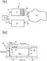
- a device 1 for the stimulation of neurons with a pathologically synchronous and oscillatory neuronal activity is shown schematically.
- the device 1 consists of a control unit 10, a stimulation unit 11 with one or more stimulation elements 12 and a measuring unit 13.
- the stimulation unit 11 contains, for example, four stimulation elements 12.
- the stimulation unit 11 can of course also have a different number of stimulation elements 12.
- the stimulation elements 12 may e.g. B. stimulation contact surfaces of one or more electrodes for application act on electrical stimuli to the neural tissue. If optically stimulated, z. B. optical fibers can be used as stimulation elements 12 to stimulate the neural tissue at the desired locations with light stimuli.
- the control unit 10 is coupled to the stimulation unit 11 and the measuring unit 13 and controls the stimulation unit 11 while the device 1 is operating. For this purpose, the control unit 10 generates control signals 21, which are received by the stimulation unit 11.
- the stimulation unit 11 is surgically implanted in the patient's body and uses the control signals 21 to generate one or more stimulation signals or stimuli 22, in particular electrical and / or optical stimulation signals 22, which are applied to the patient's tissue, in order to thereby generate neurons in a target area 30 stimulate in the patient's brain and / or spinal cord.
- the stimulation signals 22 are in particular designed to desynchronize the neurons with the pathologically synchronous and oscillatory activity when administered to the patient.
- the measuring unit 13 receives one or more measurement signals 23 measured on the patient, converts these, if necessary, into electrical signals 24 and feeds them to the control unit 10.
- the measuring unit 13 can be used to measure the neural activity in the stimulated target area 30 or in an area connected to the target area 30, the neural activity of this area correlating sufficiently closely with the neuronal activity of the target area 30.
- the stimulation effect achieved by the stimulation signals 22 can be monitored with the aid of the measuring unit 13.
- the measuring unit 13 contains one or more sensors, which in particular make it possible to record the amplitude of the pathological oscillatory neuronal activity.
- the sensors can be implanted in the patient's body.
- invasive sensors for example, epicortical electrodes, deep brain electrodes for measuring z.
- the depth electrodes for measuring the local field potentials can also be structurally combined or even identical to the electrodes used for the stimulation.
- the contacts of the electrodes can be placed in such a way that they can derive relevant neural feedback signals.
- non-invasive sensors can be used, e.g. B. chronically or intermittently used electroencephalography (EEG) - or electromyography (EMG) electrodes or magnetic encephalography (MEG) sensors.
- EEG electroencephalography
- EMG electromyography
- MEG magnetic encephalography
- the neuronal activity can also be determined by detecting characteristic movement patterns such as tremors, akinesis or epileptic seizures with the help of an accelerometer or gyroscope or indirectly by measuring the activation of the autonomic nervous system by measuring the skin resistance.
- the underlying currents can be calculated using inverse methods known to the person skilled in the art and used as the feedback modulation signals described below.
- the control unit 10 processes the signals 24, e.g. B. the signals 24 can be amplified and / or filtered. Furthermore, the control unit 10 generates a modulation signal from the signals 24 and thus from the measurement signal 23, with which the amplitude of a pulse train comprising a plurality of individual pulses is modulated.
- the control unit 10 controls the stimulation unit 11 in such a way that the at least one stimulation element 12 administers the amplitude-modulated pulse train to the tissue as the stimulation signal 22 in order to thereby stimulate the neurons in the target area 30.
- the individual pulses of the pulse train each consist of a first pulse component and a second pulse component following the first pulse component. One of the first pulse component and the second pulse component introduces charge into the tissue and the other pulse component takes charge from the tissue. Furthermore, a pause is maintained between the first pulse component and the second pulse component of the individual pulses.
- the control unit 10 can be a non-invasive unit, i. that is, during operation of the device 1, it is outside the patient's body and is not surgically implanted in the patient's body.
- the individual components of the device 1, in particular the control unit 10, the stimulation unit 11 and / or the measuring unit 13, can be structurally separate from one another.
- the device 1 can therefore also be understood as a system.
- the control unit 10 can have a processor, e.g. B. contain a microcontroller.
- the stimulation methods described herein can be stored as software code in a memory assigned to the control unit 10.
- the device 1 can be used in particular for the treatment of neurological or psychiatric disorders, e.g. B. Parkinson's disease, essential tremor, tremor due to multiple sclerosis and other pathological tremors, dystonia, epilepsy, depression, movement disorders, cerebellar disorders, obsessive-compulsive disorders, dementias, Alzheimer's disease, Tourette syndrome, autism, functional disorders after stroke, spasticity, sleep disorders, tinnitus , Schizophrenia, irritable bowel syndrome, addictive disorders, borderline personality disorder, attention deficit syndrome, attention deficit hyperactivity syndrome, gambling addiction, neuroses, feed addiction, Anorexia, eating disorders, burnout syndrome, fibromyalgia, migraines, cluster headache, general headache, neuralgia, ataxia, tic disorder or hypertension, as well as other diseases that are characterized by pathologically increased neuronal synchronization.
- neurological or psychiatric disorders e.g. B. Parkinson's disease, essential tremor,
- the aforementioned diseases can be caused by a disruption in the bioelectrical communication of neuron groups that are connected in specific circuits.
- a neuron population generates persistent pathological neural activity and possibly a pathological connectivity (network structure) associated with it.
- a large number of neurons synchronously form action potentials, i. that is, the neurons involved fire excessively synchronously.
- the diseased neuron population has an oscillatory neuronal activity, i. that is, the neurons fire rhythmically.
- the mean frequency of the abnormal rhythmic activity of the affected neuron groups is approximately in the range from 1 to 30 Hz, but can also be outside this range. In healthy people, however, the neurons fire qualitatively differently, e.g. B. in an uncorrelated manner.
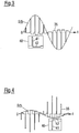
- a section of a pulse train 35 is shown by way of example, from which a stimulation signal or stimulus 22 for stimulating the neurons in the target area 30 can be generated.
- Fig. 2 shows the pulse train 35 before performing the amplitude modulation.
- the pulse train 35 consists of a large number of individual pulses 40, which are repeated periodically in particular and of which in Fig. 2 two individual pulses 40 are shown as examples.
- Fig. 2 is the amplitude or the signal strength of the individual pulses 40, z. B. in normalized units, plotted against time in ms.
- Each of the individual pulses 40 consists of a first pulse component 41, a second pulse component 42 following the first pulse component 41 and a pause 43 lying between the first pulse component 41 and the second pulse component 42.
- the first pulse component 41 has a duration t 1
- the second pulse component 42 has a duration t 2
- the pause has a duration t pause .
- the first and the second pulse component 41, 42 are designed such that one of the two pulse components 41, 42 introduces charge into the tissue and the other pulse component takes charge from the tissue.
- the first pulse portion 41 introduces charge into the tissue and the second pulse portion 42 takes charge from the tissue.
- the first pulse portion 41 takes charge from the tissue and the second pulse portion 42 releases charge to the tissue.
- the amount of the amplitude of the first pulse portion 41 is greater than the amount of the amplitude of the second pulse portion 42.
- the duration t 2 of the second pulse portion 42 is longer than the duration t 1 of the first pulse portion 41.
- the two pulse portions 41, 42 are ideally so dimensioned that the charge that is transmitted through it is the same size for both pulse components 41, 42, ie that in Fig. 2 hatched areas 44 and 45, which are obtained by integrating the pulse components 41 and 42 over time, are of equal size.
- duration t 1 is introduced into the tissue as the tissue during ladungsbalancierenden stimulation phase of duration t 2 is removed by a single pulse 40th
- Such pulses are called charge-balanced pulses.
- the duration t 1 of the first pulse component 41 is in particular in the range between 1 ⁇ s and 450 ⁇ s. If electrical stimulation is involved, the individual pulses 40 can be current- or voltage-controlled pulses. The amplitude of the The first pulse component 41 can be up to 25 mA in the case of current-controlled pulses and up to 16 V in the case of voltage-controlled pulses.
- the amplitude of the individual pulse 40 is zero, i. that is, during pause 43, no charge is introduced into the tissue nor is charge removed from the tissue.
- the individual pulses 40 of the pulse train 35 are in particular identical and are applied periodically at a frequency f stim .
- the permanent application of a pulse train 35 with a frequency f stim of at least 100 Hz is referred to as high-frequency continuous stimulation.
- the pause 43 between the two pulse components 41, 42 of an individual pulse 40 contributes significantly to the success of the stimulation.
- the duration t pause of the pause 43 is at least 1 ms.
- the duration t pause of the pause 43 is in the range from 1 ms to 6 ms. It can further be provided that the duration t pause of the pause 43 is adapted to the frequency f stim with which the individual pulses 40 are applied repetitively within the pulse train 35. The greater the frequency f stim , the shorter the period length T stim . Thus, the maximum possible duration of the pause 43 under the secondary condition that t pause ⁇ t pulse-to-pulse applies, the smaller the greater the frequency f stim .
- control unit 10 can vary the duration t pause of the pause 43 until the synchronization of the stimulated neurons is minimal or falls below a predetermined threshold value.
- the pulse train 35 with the periodically occurring individual pulses 40 is preferably applied permanently, ie for a comparatively long period of time.
- the pulse train 35 is applied for longer than 30 minutes or 1 hour or 2 hours.
- the rectangular shape of the individual pulses 40 and in particular the first and second pulse components 41, 42 shown represents an ideal shape. Depending on the quality of the electronics producing the individual pulses 40, the ideal rectangular shape is deviated from.
- Individual pulses 40 shown with the first and second pulse components 41, 42 can also be referred to as individual stimuli 40 with first and second stimulus components 41, 42, which are applied within a periodic stimulus sequence. Furthermore, instead of first and second pulse components, one can speak of first and second phases.
- the amplitude of the pulse train 35 is modulated with a modulation signal which the control unit 10 generates from the measurement signal 23. Since the measurement signal 23 reproduces the pathologically synchronous neuronal activity of the stimulated neurons, feedback amplitude modulation is consequently carried out, i. H. an amplitude modulation with a feedback signal as a modulation signal.
- the feedback modulation signal which is referred to below as S (t), is also delayed and processed linearly or non-linearly compared to the measurement signal 23 received by the measuring unit 13.
- the measurement signal 23 is first preprocessed, e.g. B. amplified and / or bandpass filtered, the physiologically relevant frequency range being let through by the bandpass filter.
- a preprocessed measurement signal 23 recorded at a time t is to be referred to as x (t) below.
- I is the parameter of the stimulation intensity
- ⁇ indicates the time delay of the feedback modulation signal S (t) compared to the measurement signal 23 or the preprocessed measurement signal x (t). Then applies to the linear time-delayed feedback modulation signal S (t):
- S t I x t - ⁇ - x t
- the stimulation elements 12 deliver the stimulation signal 22 to the neuronal Tissue and stimulate the neurons with the pathologically synchronous neuronal activity in the target area 30.
- Z * (t) gives the complex conjugate of Z (t).
- the signal y (t), which represents the imaginary part of the signal Z (t) can be obtained from the signal x (t) by means of a Hilbert transformation.
- the signal y (t) can be generated from the signal x (t) by a time delay.
- the mean period T of the pathologically synchronous oscillatory neuronal activity of the stimulated neurons can be extracted from the measurement signal 23.
- the stimulation signal 22 can be generated by multiplying the signal H (t) of the pulse train 35 by the non-linear time-delayed feedback modulation signal S (t). Furthermore, instead of the complex modulation signal S (t), only the real part of this signal can be multiplied by the signal H (t) in order to obtain the stimulation signal 22.
- the following applies to the real part of the non-linear time-delayed feedback modulation signal S (t): re S t ix t - ⁇ x 2 t - y 2 t + 2 ⁇ ix t y t y t - ⁇
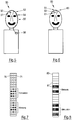
- 3 and 4 schematically show different electrical pulse trains, the amplitude of which was modulated with different feedback modulation signals S (t). 3 and 4 each contain a separate enlarged representation of the individual pulse 40 used in each case. It should be noted that in 3 and 4 for a simplified representation, the pauses 43 between the first pulse components 41 and the second pulse components 42 of the individual pulses 40 are not shown.
- the first pulse portion 41 is in each case an anodic, positive phase and the second pulse portion 42 is a cathodic, negative phase.
- Fig. 4 are the polarities of the two pulse components 41, 42 with respect to the pulse train 35 Fig. 3 interchanged so that the first pulse portion 41 is a cathodic phase and the second pulse portion 42 is an anodic phase.
- the individual pulses 40 are dimensioned even after the amplitude modulation with the feedback modulation signal S (t) such that the same amount of charge is introduced into the tissue during the actual stimulation phase by a single pulse 40 as is taken from the tissue during the charge-balancing stimulation phase ,
- a pulse train 35 inserts a pause 43 between the first pulse component 41 and the second pulse component 42 of the individual pulses 40 and modulates the amplitude of the pulse train 35 with the linear or non-linear time-delayed feedback stimulation signal S (t), a fully pronounced desynchronization is achieved , A significant improvement in the desynchronization is achieved with a duration t pause of pause 43 of 1 ms. Better values for the duration t pause of pause 43 amount to z. B. 5 ms.
- the high-frequency continuous stimulation with both linear and non-linear time-delayed feedback amplitude modulation and individual pulses with pauses between the pulse components are comparable with regard to the dependence of the desynchronization effect on the time delay.
- the non-linear variant is no longer clearly superior, as is the case with conventional time-delayed feedback stimulation.
- the technically easier to implement variant that is the high-frequency continuous stimulation with linear time-delayed feedback amplitude modulation and individual pulses with pauses between the pulse components, can be used.
- the particularly undelayed signal is also used. In comparison, it is easier to simply delay the signal component - as in the linear variant.
- control unit 10 varies the time delay ⁇ of the feedback modulation signal S (t) compared to the measurement signal 23 or the preprocessed measurement signal x (t).
- the variation of the time delay ⁇ can in particular continue until the synchronization of the stimulated neurons is minimal or falls below a predetermined threshold value.
- the optimal time delay ⁇ can e.g. B. in the range of 0.5 to 2.5 times or 1.5 to 2.5 times the mean period of the abnormal rhythmic activity of the affected neuron population.
- the time delay ⁇ can be in a range from 5 ms to 2 s.
- the optimal value for the time delay ⁇ can also - z. B. caused by internal time delays in the neuron population and thus interacting neuron populations - differ greatly.
- the dependence of the success of the stimulation on the time delay ⁇ is shown by those explained below Figures 11 and 14 ,
- the time delays associated with areas of local minimums of the synchronization typically repeat after a multiple of the mean period.
- the time delays ⁇ opt + T mean or ⁇ opt + 2 T mean are also suitable for a pronounced desynchronization, T mean denoting the mean period of the pathological rhythmic activity of the affected neuron population.
- the following calibration procedure can therefore be carried out:
- the mean period T average is determined or a value known to the person skilled in the art is taken as the starting point. The latter is possible because the pathological oscillatory activity is in typical frequency bands.
- the parameter ⁇ is allowed to grow slowly until a pronounced desynchronization occurs, ie, the synchronization of the stimulated ones Neurons reach a local minimum or fall below a predetermined threshold.
- a further increase then leads to a decrease in desynchronization.
- the intensity, ie in particular the amplitude of the stimulation can be slowly increased at the previously determined fixed value for ⁇ in order to be able to achieve an even more efficient desynchronization.
- the increase in intensity can e.g. B. continue until the synchronization of the stimulated neurons reaches a further local minimum or falls below a further predetermined threshold value.
- Fig. 5 schematically shows a device 50 for invasive electrical stimulation of neurons with a pathologically synchronous and oscillatory neuronal activity according to an embodiment of the invention.
- the device 50 comprises two deep brain electrodes 51, 52, which are implanted in the patient's brain and are connected to a connector 54 via cables 53.
- the connector 54 is in turn connected to a control unit 56 via a cable 55.
- the control unit 56 generates the stimulation signals based on the measured feedback signals.
- the stimulation signals can be generated separately for both brain electrodes 51, 52. However, it can also be stimulated via one of the two brain electrodes 51, 52 and measured via the other brain electrode.
- the device 50 can have the function of the device 1 described above.
- Fig. 6 schematically shows a further device 60 for invasive electrical stimulation of neurons with a pathologically synchronous and oscillatory neuronal activity according to a further embodiment of the invention.
- the device 60 comprises two implanted deep brain electrodes 61, 62.
- the device 60 further comprises a control unit 63 implanted in the borehole, which is connected directly to the brain electrode 62.
- the brain electrode 61 is connected to the control unit 63 via a cable 64.
- the stimulation signals can be generated separately for both brain electrodes 61, 62. However, it can also be stimulated via one of the two brain electrodes 61, 62 and measured via the other brain electrode.
- the device 60 can have the same functions as the device 1.
- Fig. 7 schematically shows a multi-channel electrode 70, which serves as a stimulation unit 11 and has a plurality of electrically conductive contacts or stimulation contact surfaces 71 arranged in an array, which represent the stimulation elements 12.
- the contacts 71 can be individually controllable, so that a desired electrical stimulation signal 22 can be applied via each contact 71.
- the stimulation signal 22 can be applied spatially weighted according to anatomical and / or physiological boundary conditions via a plurality of contacts 71.
- the contacts 71 can also be used to measure neuronal activity. Measuring or stimulation contacts 71 are shown in Fig. 7 each illustrated by dark panes. For example, measurements or stimulations are carried out over different groups of contacts 71.
- Fig. 8 schematically shows a multi-channel electrode 80, which serves as a stimulation unit 11 and has a multiplicity of ring-shaped, electrically conductive contacts or stimulation contact surfaces 81, which represent the stimulation elements 12. For example, measurements are carried out or stimulated via contacts 81 marked in dark, while contacts 81 are neither measured nor stimulated via contacts 81 marked in white.
- Fig. 9 shows schematically multi-channel electrodes 90, 91, each of which has a multiplicity of electrically conductive contacts 92 arranged in an array.
- the multichannel electrodes 90, 91 stimulate two interacting neuron populations 93, 94 in the target area 30.
- the multi-channel electrode 90 is placed directly on the target area 30 for direct stimulation of the neuron populations 93, 94. In this way, the somata, axons and dendrites of the neuron populations 93, 94 can be stimulated directly.
- the neuron populations 93, 94 are stimulated with the dark fill via the contacts 92 assigned to the neuron populations 93, 94.
- a group of contacts 92 is assigned to each of the neuron populations 93, 94.
- a measurement signal which reflects the neuronal activity of the stimulated neuron populations 93, 94, can be derived via the multi-channel electrode 90.
- the multi-channel electrode 91 is not placed directly on the target area 30, rather afferent fibers 95, which lead to and / or arise from the neuron populations 93, 94, are stimulated.
- groups 96, 97 are each formed from a plurality of contacts 92, and groups 96, 97 indirectly stimulate the neuron populations 93, 94 via the afferent fibers 95.
- the contacts 92 of the groups 96, 97 are in Fig. 9 shown with a dark fill.
- Implantable stimulation units 11 for the optical stimulation of neuronal tissue are known.
- a light source such as. B. a laser, a laser diode or an LED, generate a light beam that is distributed with the aid of a light coupling to the inputs of a fiber bundle consisting of several optical fibers.
- a control unit 10 gives z. B. before, at which time a single light pulse or a train of light pulses is coupled into which fiber of the fiber bundle.
- the decoupling points of the individual fibers of the fiber bundle, i.e. H. the ends of the fibers may be at different locations in the target area 30 in the patient's brain and / or spinal cord.
- the light stimulates different locations of the target area 30 in a time sequence predetermined by the control unit 10.
- implantable stimulation units 11 that are suitable for direct optical stimulation of neuronal tissue can also be used.
- optical stimulation signals 22 the light intensity of a pulse train is amplitude-modulated with the feedback modulation signal S (t).
- Fig. 10 shown by the rate of fire of a neuron population.
- the rate of fire indicates the relative number of neurons firing at a given time.
- the rate of fire of the neurons is plotted against time.
- the rhythmic firing of the neurons of the pathologically active neuron population before stimulation is shown.
- the synchronization of the neurons becomes significant through continuous high-frequency stimulation with a non-linear, time-delayed feedback amplitude modulation reduced, like the two lower representations of Fig. 10 demonstrate.
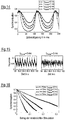
- Fig. 11 shows the degree of synchronization of a neuron population with a pathologically synchronous and oscillatory neuronal activity as a function of the time delay ⁇ for high-frequency continuous stimulation with a non-linear time-delayed feedback amplitude modulation.
- the time delay ⁇ determines the time period by which the feedback modulation signal S (t) is delayed compared to the measurement signal x (t).
- the simulation was carried out for single pulses with pauses t pause of 0, 2 or 5 ms and fixed stimulation intensity I.
- the horizontal dashed line in Fig. 11 indicates the degree of synchronization of the neuron population before stimulation.
- Fig. 11 it can be seen that for certain sub-areas of the time delay ⁇ a significantly more effective desynchronization of the neuron population can be achieved if a pause is maintained between the pulse components of the individual pulses.
- the desynchronization effect achieved by the pause between the pulse components of the individual pulses also increases with an increasing stimulation intensity I.
- This property is in Fig. 12 shown in which the degree of synchronization of the stimulated neuron population against the stimulation intensity I is plotted for a fixed time delay ⁇ of 40 ms and values for the pause t pause of 0, 1, 2 or 5 ms.
- high-frequency continuous stimulation with a non-linear, time-delayed feedback amplitude modulation without a pause between the individual pulses only desynchronizes the neuron population to a certain degree.
- the same stimulation with a pause between the individual pulses gives much better results.
- a higher stimulation intensity I leads to a stronger desynchronization of the neuron population.
- Fig. 13 The effectiveness of the stimulation described herein is in Fig. 13 shown in which the degree of synchronization is plotted against the amount of stimulation administered.
- the amount of stimulation administered is given by the amplitude of the feedback modulation signal S (t), as exemplified in 3 and 4 is shown.
- the in Fig. 13 The values shown are based on a simulation of a high-frequency continuous stimulation with a non-linear time-delayed feedback amplitude modulation with a fixed time delay ⁇ of 150 ms and pauses t pause of 0, 1, 2 or 5 ms.
- Fig. 13 shows that stimulation with a longer pause t pause requires a smaller amount of the stimulation administered to achieve the same desynchronization effect as a stimulation with a shorter pause t pause .
- Fig. 14 the degree of synchronization of a neuron population with a pathologically synchronous and oscillatory neuronal activity as a function of the time delay ⁇ for high-frequency continuous stimulation with a linear time-delayed feedback amplitude modulation.
- the simulation was carried out for single pulses with pauses t pause of 0, 1, 2 or 5 ms and fixed stimulation intensity I.
- the horizontal dashed line in Fig. 14 indicates the degree of synchronization of the neuron population before stimulation.
- a comparison with the in Fig. 11 Results shown shows that the linear time-delayed feedback amplitude modulation of the non-linear time-delayed feedback amplitude modulation for certain values of the time delay ⁇ with otherwise identical parameters is superior.
- Fig. 15 the rate of fire of the neurons is plotted against the time, which is brought about by high-frequency continuous stimulation with linear, time-delayed feedback amplitude modulation and individual pulses with or without a pause t pause between the pulse components.
- stimulation with individual pulses that have a pause t pause of 5 ms between the first and second pulse components is clearly superior to stimulation with individual pulses, the first and second pulse components of which follow one another directly ,
- Fig. 16 the degree of synchronization is plotted against the amount of stimulation administered, which is achieved with high-frequency continuous stimulation with linear time-delayed feedback amplitude modulation with a fixed time delay ⁇ of 70 ms and pauses t pause of 0, 1, 2 or 5 ms leaves.
- stimulation with a longer pause t pause leads to the same desynchronization effect as stimulation with a shorter pause t pause , but with a higher amount of the stimulation administered.
Landscapes
- Health & Medical Sciences (AREA)
- Life Sciences & Earth Sciences (AREA)
- Engineering & Computer Science (AREA)
- Biomedical Technology (AREA)
- Animal Behavior & Ethology (AREA)
- Veterinary Medicine (AREA)
- Public Health (AREA)
- General Health & Medical Sciences (AREA)
- Nuclear Medicine, Radiotherapy & Molecular Imaging (AREA)
- Radiology & Medical Imaging (AREA)
- Neurosurgery (AREA)
- Neurology (AREA)
- Pathology (AREA)
- Biophysics (AREA)
- Physics & Mathematics (AREA)
- Molecular Biology (AREA)
- Surgery (AREA)
- Heart & Thoracic Surgery (AREA)
- Medical Informatics (AREA)
- Pain & Pain Management (AREA)
- Orthopedic Medicine & Surgery (AREA)
- Optics & Photonics (AREA)
- Electrotherapy Devices (AREA)
Applications Claiming Priority (2)
| Application Number | Priority Date | Filing Date | Title |
|---|---|---|---|
| DE102016104913.1A DE102016104913B4 (de) | 2016-03-16 | 2016-03-16 | Vorrichtung zur effektiven, invasiven und amplitudenmodulierten Neurostimulation |
| PCT/EP2017/055915 WO2017157890A1 (de) | 2016-03-16 | 2017-03-14 | Vorrichtung zur effektiven, invasiven und amplitudenmodulierten neurostimulation |
Publications (2)
| Publication Number | Publication Date |
|---|---|
| EP3429682A1 EP3429682A1 (de) | 2019-01-23 |
| EP3429682B1 true EP3429682B1 (de) | 2020-01-29 |
Family
ID=58314188
Family Applications (1)
| Application Number | Title | Priority Date | Filing Date |
|---|---|---|---|
| EP17710870.1A Active EP3429682B1 (de) | 2016-03-16 | 2017-03-14 | Vorrichtung zur effektiven, invasiven und amplitudenmodulierten neurostimulation |
Country Status (8)
| Country | Link |
|---|---|
| US (1) | US11013918B2 (enExample) |
| EP (1) | EP3429682B1 (enExample) |
| JP (1) | JP6937767B2 (enExample) |
| CN (1) | CN109069829B (enExample) |
| AU (1) | AU2017235269B2 (enExample) |
| DE (1) | DE102016104913B4 (enExample) |
| ES (1) | ES2784002T3 (enExample) |
| WO (1) | WO2017157890A1 (enExample) |
Cited By (1)
| Publication number | Priority date | Publication date | Assignee | Title |
|---|---|---|---|---|
| WO2021257548A1 (en) * | 2020-06-18 | 2021-12-23 | Diagnostyx, Inc. | Treatment of neurological abnormalities using dynamic electroencephalography |
Families Citing this family (11)
| Publication number | Priority date | Publication date | Assignee | Title |
|---|---|---|---|---|
| US10780274B2 (en) | 2016-08-22 | 2020-09-22 | Boston Scientific Neuromodulation Corporation | Systems and methods for delivering spinal cord stimulation therapy |
| WO2020186203A1 (en) * | 2019-03-14 | 2020-09-17 | University Of Connecticut | Deep brain stimulation system with amplitude-modulated temporal patterns |
| CN113573655B (zh) * | 2019-03-15 | 2025-05-27 | 波士顿科学国际有限公司 | 用于选择性细胞消融的空间复用波形 |
| CN111030134B (zh) * | 2019-10-17 | 2021-09-03 | 武汉大学 | 一种基于圆盘定理的次/超同步振荡控制方法 |
| US11697023B2 (en) * | 2020-03-30 | 2023-07-11 | Medtronic, Inc. | Medical device and method for generating modulated high frequency electrical stimulation pulses |
| WO2021247661A1 (en) * | 2020-06-02 | 2021-12-09 | University Of Washington | High frequency epidural stimulation to control sensation |
| US11872397B2 (en) * | 2020-07-22 | 2024-01-16 | Nexalin Technology, Inc. | Transcranial alternating current dynamic frequency stimulation (TACS) system |
| CN111973181B (zh) * | 2020-08-24 | 2023-12-08 | 中国科学院上海微系统与信息技术研究所 | 一种集成采集刺激功能的皮层脑电极及其制作方法 |
| CN115177256B (zh) * | 2022-09-13 | 2022-11-29 | 北京昆迈医疗科技有限公司 | 一种视频脑磁图系统 |
| LU505149B1 (en) * | 2023-09-22 | 2025-03-25 | Precisis Gmbh | A method for suppression of seizures, and a related neurological stimulation device |
| WO2026002049A1 (zh) * | 2024-06-28 | 2026-01-02 | 杭州诺为医疗技术有限公司 | 脉冲发生器及电刺激设备 |
Family Cites Families (22)
| Publication number | Priority date | Publication date | Assignee | Title |
|---|---|---|---|---|
| US6944501B1 (en) * | 2000-04-05 | 2005-09-13 | Neurospace, Inc. | Neurostimulator involving stimulation strategies and process for using it |
| DE10233960B4 (de) * | 2002-07-29 | 2006-11-02 | Forschungszentrum Jülich GmbH | Vorrichtung zur bedarfsgesteuerten Modulation physiologischer und pathologischer neuronaler rhythmischer Aktivität im Gehirn mittels sensorischer Stimulation |
| DE10318071A1 (de) * | 2003-04-17 | 2004-11-25 | Forschungszentrum Jülich GmbH | Vorrichtung zur Desynchronisation von neuronaler Hirnaktivität |
| DE10355652A1 (de) * | 2003-11-28 | 2005-06-30 | Forschungszentrum Jülich GmbH | Verfahren und Vorrichtung zur Desynchronisation neuronaler Hirnaktivität |
| DE102004025945A1 (de) * | 2004-05-27 | 2005-12-29 | Forschungszentrum Jülich GmbH | Verfahren und Vorrichtung zur Entkopplung und/oder Desynchronisation neuronaler Hirnaktivität |
| DE102004060514A1 (de) * | 2004-12-16 | 2006-06-29 | Forschungszentrum Jülich GmbH | Verfahren und Vorrichtung zur Desynchronisation neuronaler Hirnaktivität, Steuerung, sowie Verfahren zur Behandlung neuronaler und/oder psychiatrischer Erkrankungen |
| DE102005014383A1 (de) * | 2005-03-24 | 2006-09-28 | Forschungszentrum Jülich GmbH | Impulsstimulationsvorrichtung und Verfahren, mit deren Hilfe unerwünschte Synchronisierung ausgeschaltet oder gesteuert werden kann |
| JP2006271907A (ja) * | 2005-03-25 | 2006-10-12 | Hideo Yamamura | 生体刺激用装置、イオン導入装置等、および、生体刺激用プログラム、イオン導入装置等用プログラム。 |
| US8406876B2 (en) * | 2005-04-05 | 2013-03-26 | Cardiac Pacemakers, Inc. | Closed loop neural stimulation synchronized to cardiac cycles |
| US8103341B2 (en) * | 2006-08-25 | 2012-01-24 | Cardiac Pacemakers, Inc. | System for abating neural stimulation side effects |
| US8121692B2 (en) * | 2006-08-30 | 2012-02-21 | Cardiac Pacemakers, Inc. | Method and apparatus for neural stimulation with respiratory feedback |
| DE102007051848B4 (de) * | 2007-10-30 | 2014-01-02 | Forschungszentrum Jülich GmbH | Vorrichtung zur Stimulation von Neuronenverbänden |
| DE102008015259B4 (de) * | 2008-03-20 | 2010-07-22 | Anm Adaptive Neuromodulation Gmbh | Vorrichtung und Verfahren zur auditorischen Stimulation |
| WO2009151516A2 (en) * | 2008-05-08 | 2009-12-17 | Cardiac Pacemakers, Inc. | Smart delay for intermittent stress therapy |
| DE102008052078B4 (de) * | 2008-10-17 | 2011-06-01 | Forschungszentrum Jülich GmbH | Vorrichtung zur konditionierten desynchronisierenden Stimulation |
| US20100228310A1 (en) * | 2009-03-09 | 2010-09-09 | Shuros Allan C | Systems and methods for autonomic nerve modulation |
| WO2011050255A2 (en) * | 2009-10-22 | 2011-04-28 | Research Foundation Of The City University Of New York | Dipole electrical stimulation employing direct current for recovery from spinal cord injury |
| WO2011051955A2 (en) * | 2009-11-02 | 2011-05-05 | Jonathan Bentwich | Computerized system or device and method for diagnosis and treatment of human, physical and planetary conditions |
| DE102010016404A1 (de) | 2010-04-12 | 2012-12-27 | Forschungszentrum Jülich GmbH | Vorrichtung und Verfahren zur konditionierten desynchronisierenden nicht-invasiven Stimulation |
| DE102012002436B4 (de) * | 2012-02-08 | 2014-08-21 | Forschungszentrum Jülich GmbH | Vorrichtung zur Eichung einer nicht-invasiven desynchronisierenden Neurostimulation |
| WO2014130858A1 (en) * | 2013-02-22 | 2014-08-28 | Boston Scientific Neuromodulation Corporation | Multi-channel neuromodulation system with means for combining pulse trains |
| DE102013013278A1 (de) * | 2013-08-08 | 2015-02-12 | Forschungszentrum Jülich GmbH | Vorrichtung und Verfahren zur Eichung einer akustischen desynchronisierenden Neurostimulation |
-
2016
- 2016-03-16 DE DE102016104913.1A patent/DE102016104913B4/de active Active
-
2017
- 2017-03-14 EP EP17710870.1A patent/EP3429682B1/de active Active
- 2017-03-14 US US16/084,751 patent/US11013918B2/en active Active
- 2017-03-14 WO PCT/EP2017/055915 patent/WO2017157890A1/de not_active Ceased
- 2017-03-14 CN CN201780017882.4A patent/CN109069829B/zh active Active
- 2017-03-14 AU AU2017235269A patent/AU2017235269B2/en active Active
- 2017-03-14 ES ES17710870T patent/ES2784002T3/es active Active
- 2017-03-14 JP JP2018545345A patent/JP6937767B2/ja active Active
Non-Patent Citations (1)
| Title |
|---|
| None * |
Cited By (3)
| Publication number | Priority date | Publication date | Assignee | Title |
|---|---|---|---|---|
| WO2021257548A1 (en) * | 2020-06-18 | 2021-12-23 | Diagnostyx, Inc. | Treatment of neurological abnormalities using dynamic electroencephalography |
| US11344745B2 (en) | 2020-06-18 | 2022-05-31 | Diagnostyx, Inc. | Treatment of neurological abnormalities using dynamic electroencephalography |
| US11890489B2 (en) | 2020-06-18 | 2024-02-06 | Diagnostyx, Inc. | Treatment of neurological abnormalities using dynamic electroencephalography |
Also Published As
| Publication number | Publication date |
|---|---|
| DE102016104913B4 (de) | 2018-04-26 |
| DE102016104913A1 (de) | 2017-09-21 |
| US20190083785A1 (en) | 2019-03-21 |
| EP3429682A1 (de) | 2019-01-23 |
| JP2019508138A (ja) | 2019-03-28 |
| CN109069829A (zh) | 2018-12-21 |
| WO2017157890A1 (de) | 2017-09-21 |
| AU2017235269B2 (en) | 2020-05-21 |
| US11013918B2 (en) | 2021-05-25 |
| JP6937767B2 (ja) | 2021-09-22 |
| CN109069829B (zh) | 2022-07-05 |
| AU2017235269A1 (en) | 2018-09-20 |
| ES2784002T3 (es) | 2020-09-21 |
Similar Documents
| Publication | Publication Date | Title |
|---|---|---|
| EP3429682B1 (de) | Vorrichtung zur effektiven, invasiven und amplitudenmodulierten neurostimulation | |
| EP1944059B1 (de) | Vorrichtung zur Desynchronisation von neuronaler Hirnaktivität | |
| EP1691887B1 (de) | Vorrichtung zur desynchronisation neuronaler hirnaktivität | |
| DE102007051848B4 (de) | Vorrichtung zur Stimulation von Neuronenverbänden | |
| EP1827586B1 (de) | Vorrichtung zur desynchronisation neuronaler hirnaktivität | |
| DE102007051847B4 (de) | Vorrichtung zur Stimulation von Neuronen mit einer krankhaft synchronen und oszillatorischen neuronalen Aktivität | |
| EP2797666B1 (de) | Vorrichtung zur eichung einer invasiven, elektrischen und desynchronisierenden neurostimulation | |
| EP3397336B1 (de) | Vorrichtung zur effektiven invasiven mehrsegment-neurostimulation | |
| EP3183030B1 (de) | Vorrichtung zur effektiven invasiven desynchronisierenden neurostimulation | |
| WO2005113063A1 (de) | Vorrichtung zur behandlung von patienten mittels hirnstimulation, ein elektronisches bauteil sowie die verwendung der vorrichtung und des elektronischen bauteils in der medizin und medizinisches behandlungsverfahren | |
| EP3183032B1 (de) | Vorrichtung zur effektiven invasiven neurostimulation mittels variierender reizsequenzen | |
| EP3285854B1 (de) | Vorrichtung zur effektiven invasiven zwei-stufen-neurostimulation | |
| DE102009015723B4 (de) | Stimulationselektrode | |
| DE102008039387B4 (de) | Vorrichtung zur transkutanen Stimulation |
Legal Events
| Date | Code | Title | Description |
|---|---|---|---|
| STAA | Information on the status of an ep patent application or granted ep patent |
Free format text: STATUS: UNKNOWN |
|
| STAA | Information on the status of an ep patent application or granted ep patent |
Free format text: STATUS: THE INTERNATIONAL PUBLICATION HAS BEEN MADE |
|
| PUAI | Public reference made under article 153(3) epc to a published international application that has entered the european phase |
Free format text: ORIGINAL CODE: 0009012 |
|
| STAA | Information on the status of an ep patent application or granted ep patent |
Free format text: STATUS: REQUEST FOR EXAMINATION WAS MADE |
|
| 17P | Request for examination filed |
Effective date: 20181012 |
|
| AK | Designated contracting states |
Kind code of ref document: A1 Designated state(s): AL AT BE BG CH CY CZ DE DK EE ES FI FR GB GR HR HU IE IS IT LI LT LU LV MC MK MT NL NO PL PT RO RS SE SI SK SM TR |
|
| AX | Request for extension of the european patent |
Extension state: BA ME |
|
| DAV | Request for validation of the european patent (deleted) | ||
| DAX | Request for extension of the european patent (deleted) | ||
| GRAP | Despatch of communication of intention to grant a patent |
Free format text: ORIGINAL CODE: EPIDOSNIGR1 |
|
| STAA | Information on the status of an ep patent application or granted ep patent |
Free format text: STATUS: GRANT OF PATENT IS INTENDED |
|
| RIC1 | Information provided on ipc code assigned before grant |
Ipc: A61N 5/06 20060101ALI20190719BHEP Ipc: A61B 5/00 20060101ALI20190719BHEP Ipc: A61B 5/04 20060101ALI20190719BHEP Ipc: A61N 5/067 20060101ALI20190719BHEP Ipc: A61N 1/36 20060101AFI20190719BHEP |
|
| INTG | Intention to grant announced |
Effective date: 20190814 |
|
| GRAS | Grant fee paid |
Free format text: ORIGINAL CODE: EPIDOSNIGR3 |
|
| GRAA | (expected) grant |
Free format text: ORIGINAL CODE: 0009210 |
|
| STAA | Information on the status of an ep patent application or granted ep patent |
Free format text: STATUS: THE PATENT HAS BEEN GRANTED |
|
| AK | Designated contracting states |
Kind code of ref document: B1 Designated state(s): AL AT BE BG CH CY CZ DE DK EE ES FI FR GB GR HR HU IE IS IT LI LT LU LV MC MK MT NL NO PL PT RO RS SE SI SK SM TR |
|
| REG | Reference to a national code |
Ref country code: GB Ref legal event code: FG4D Free format text: NOT ENGLISH |
|
| REG | Reference to a national code |
Ref country code: CH Ref legal event code: EP |
|
| REG | Reference to a national code |
Ref country code: AT Ref legal event code: REF Ref document number: 1228060 Country of ref document: AT Kind code of ref document: T Effective date: 20200215 |
|
| REG | Reference to a national code |
Ref country code: IE Ref legal event code: FG4D Free format text: LANGUAGE OF EP DOCUMENT: GERMAN |
|
| REG | Reference to a national code |
Ref country code: DE Ref legal event code: R096 Ref document number: 502017003639 Country of ref document: DE |
|
| REG | Reference to a national code |
Ref country code: NL Ref legal event code: FP |
|
| PG25 | Lapsed in a contracting state [announced via postgrant information from national office to epo] |
Ref country code: NO Free format text: LAPSE BECAUSE OF FAILURE TO SUBMIT A TRANSLATION OF THE DESCRIPTION OR TO PAY THE FEE WITHIN THE PRESCRIBED TIME-LIMIT Effective date: 20200429 Ref country code: FI Free format text: LAPSE BECAUSE OF FAILURE TO SUBMIT A TRANSLATION OF THE DESCRIPTION OR TO PAY THE FEE WITHIN THE PRESCRIBED TIME-LIMIT Effective date: 20200129 Ref country code: RS Free format text: LAPSE BECAUSE OF FAILURE TO SUBMIT A TRANSLATION OF THE DESCRIPTION OR TO PAY THE FEE WITHIN THE PRESCRIBED TIME-LIMIT Effective date: 20200129 Ref country code: PT Free format text: LAPSE BECAUSE OF FAILURE TO SUBMIT A TRANSLATION OF THE DESCRIPTION OR TO PAY THE FEE WITHIN THE PRESCRIBED TIME-LIMIT Effective date: 20200621 |
|
| REG | Reference to a national code |
Ref country code: LT Ref legal event code: MG4D |
|
| PG25 | Lapsed in a contracting state [announced via postgrant information from national office to epo] |
Ref country code: HR Free format text: LAPSE BECAUSE OF FAILURE TO SUBMIT A TRANSLATION OF THE DESCRIPTION OR TO PAY THE FEE WITHIN THE PRESCRIBED TIME-LIMIT Effective date: 20200129 Ref country code: SE Free format text: LAPSE BECAUSE OF FAILURE TO SUBMIT A TRANSLATION OF THE DESCRIPTION OR TO PAY THE FEE WITHIN THE PRESCRIBED TIME-LIMIT Effective date: 20200129 Ref country code: BG Free format text: LAPSE BECAUSE OF FAILURE TO SUBMIT A TRANSLATION OF THE DESCRIPTION OR TO PAY THE FEE WITHIN THE PRESCRIBED TIME-LIMIT Effective date: 20200429 Ref country code: GR Free format text: LAPSE BECAUSE OF FAILURE TO SUBMIT A TRANSLATION OF THE DESCRIPTION OR TO PAY THE FEE WITHIN THE PRESCRIBED TIME-LIMIT Effective date: 20200430 Ref country code: IS Free format text: LAPSE BECAUSE OF FAILURE TO SUBMIT A TRANSLATION OF THE DESCRIPTION OR TO PAY THE FEE WITHIN THE PRESCRIBED TIME-LIMIT Effective date: 20200529 Ref country code: LV Free format text: LAPSE BECAUSE OF FAILURE TO SUBMIT A TRANSLATION OF THE DESCRIPTION OR TO PAY THE FEE WITHIN THE PRESCRIBED TIME-LIMIT Effective date: 20200129 |
|
| REG | Reference to a national code |
Ref country code: ES Ref legal event code: FG2A Ref document number: 2784002 Country of ref document: ES Kind code of ref document: T3 Effective date: 20200921 |
|
| PG25 | Lapsed in a contracting state [announced via postgrant information from national office to epo] |
Ref country code: CZ Free format text: LAPSE BECAUSE OF FAILURE TO SUBMIT A TRANSLATION OF THE DESCRIPTION OR TO PAY THE FEE WITHIN THE PRESCRIBED TIME-LIMIT Effective date: 20200129 Ref country code: MC Free format text: LAPSE BECAUSE OF FAILURE TO SUBMIT A TRANSLATION OF THE DESCRIPTION OR TO PAY THE FEE WITHIN THE PRESCRIBED TIME-LIMIT Effective date: 20200129 Ref country code: SK Free format text: LAPSE BECAUSE OF FAILURE TO SUBMIT A TRANSLATION OF THE DESCRIPTION OR TO PAY THE FEE WITHIN THE PRESCRIBED TIME-LIMIT Effective date: 20200129 Ref country code: DK Free format text: LAPSE BECAUSE OF FAILURE TO SUBMIT A TRANSLATION OF THE DESCRIPTION OR TO PAY THE FEE WITHIN THE PRESCRIBED TIME-LIMIT Effective date: 20200129 Ref country code: EE Free format text: LAPSE BECAUSE OF FAILURE TO SUBMIT A TRANSLATION OF THE DESCRIPTION OR TO PAY THE FEE WITHIN THE PRESCRIBED TIME-LIMIT Effective date: 20200129 Ref country code: SM Free format text: LAPSE BECAUSE OF FAILURE TO SUBMIT A TRANSLATION OF THE DESCRIPTION OR TO PAY THE FEE WITHIN THE PRESCRIBED TIME-LIMIT Effective date: 20200129 Ref country code: RO Free format text: LAPSE BECAUSE OF FAILURE TO SUBMIT A TRANSLATION OF THE DESCRIPTION OR TO PAY THE FEE WITHIN THE PRESCRIBED TIME-LIMIT Effective date: 20200129 Ref country code: LT Free format text: LAPSE BECAUSE OF FAILURE TO SUBMIT A TRANSLATION OF THE DESCRIPTION OR TO PAY THE FEE WITHIN THE PRESCRIBED TIME-LIMIT Effective date: 20200129 |
|
| REG | Reference to a national code |
Ref country code: CH Ref legal event code: PL Ref country code: DE Ref legal event code: R097 Ref document number: 502017003639 Country of ref document: DE |
|
| PLBE | No opposition filed within time limit |
Free format text: ORIGINAL CODE: 0009261 |
|
| STAA | Information on the status of an ep patent application or granted ep patent |
Free format text: STATUS: NO OPPOSITION FILED WITHIN TIME LIMIT |
|
| REG | Reference to a national code |
Ref country code: BE Ref legal event code: MM Effective date: 20200331 |
|
| PG25 | Lapsed in a contracting state [announced via postgrant information from national office to epo] |
Ref country code: LU Free format text: LAPSE BECAUSE OF NON-PAYMENT OF DUE FEES Effective date: 20200314 |
|
| 26N | No opposition filed |
Effective date: 20201030 |
|
| PG25 | Lapsed in a contracting state [announced via postgrant information from national office to epo] |
Ref country code: CH Free format text: LAPSE BECAUSE OF NON-PAYMENT OF DUE FEES Effective date: 20200331 Ref country code: LI Free format text: LAPSE BECAUSE OF NON-PAYMENT OF DUE FEES Effective date: 20200331 |
|
| PG25 | Lapsed in a contracting state [announced via postgrant information from national office to epo] |
Ref country code: PL Free format text: LAPSE BECAUSE OF FAILURE TO SUBMIT A TRANSLATION OF THE DESCRIPTION OR TO PAY THE FEE WITHIN THE PRESCRIBED TIME-LIMIT Effective date: 20200129 Ref country code: BE Free format text: LAPSE BECAUSE OF NON-PAYMENT OF DUE FEES Effective date: 20200331 Ref country code: SI Free format text: LAPSE BECAUSE OF FAILURE TO SUBMIT A TRANSLATION OF THE DESCRIPTION OR TO PAY THE FEE WITHIN THE PRESCRIBED TIME-LIMIT Effective date: 20200129 |
|
| REG | Reference to a national code |
Ref country code: DE Ref legal event code: R082 Ref document number: 502017003639 Country of ref document: DE Representative=s name: DF-MP DOERRIES FRANK-MOLNIA & POHLMAN PATENTAN, DE Ref country code: DE Ref legal event code: R082 Ref document number: 502017003639 Country of ref document: DE Representative=s name: DF-MP PATENTANWAELTE RECHTSANWAELTE PARTG MBB, DE |
|
| REG | Reference to a national code |
Ref country code: DE Ref legal event code: R081 Ref document number: 502017003639 Country of ref document: DE Owner name: BOSTON SCIENTIFIC NEUROMODULATION CORP., VALEN, US Free format text: FORMER OWNER: FORSCHUNGSZENTRUM JUELICH GMBH, 52428 JUELICH, DE |
|
| REG | Reference to a national code |
Ref country code: DE Ref legal event code: R081 Ref document number: 502017003639 Country of ref document: DE Owner name: BOSTON SCIENTIFIC NEUROMODULATION CORP., VALEN, US Free format text: FORMER OWNER: TASS, PETER, PROF. DR. DR., 83684 TEGERNSEE, DE |
|
| PG25 | Lapsed in a contracting state [announced via postgrant information from national office to epo] |
Ref country code: TR Free format text: LAPSE BECAUSE OF FAILURE TO SUBMIT A TRANSLATION OF THE DESCRIPTION OR TO PAY THE FEE WITHIN THE PRESCRIBED TIME-LIMIT Effective date: 20200129 Ref country code: MT Free format text: LAPSE BECAUSE OF FAILURE TO SUBMIT A TRANSLATION OF THE DESCRIPTION OR TO PAY THE FEE WITHIN THE PRESCRIBED TIME-LIMIT Effective date: 20200129 Ref country code: CY Free format text: LAPSE BECAUSE OF FAILURE TO SUBMIT A TRANSLATION OF THE DESCRIPTION OR TO PAY THE FEE WITHIN THE PRESCRIBED TIME-LIMIT Effective date: 20200129 |
|
| PG25 | Lapsed in a contracting state [announced via postgrant information from national office to epo] |
Ref country code: MK Free format text: LAPSE BECAUSE OF FAILURE TO SUBMIT A TRANSLATION OF THE DESCRIPTION OR TO PAY THE FEE WITHIN THE PRESCRIBED TIME-LIMIT Effective date: 20200129 Ref country code: AL Free format text: LAPSE BECAUSE OF FAILURE TO SUBMIT A TRANSLATION OF THE DESCRIPTION OR TO PAY THE FEE WITHIN THE PRESCRIBED TIME-LIMIT Effective date: 20200129 |
|
| REG | Reference to a national code |
Ref country code: AT Ref legal event code: MM01 Ref document number: 1228060 Country of ref document: AT Kind code of ref document: T Effective date: 20220314 |
|
| PG25 | Lapsed in a contracting state [announced via postgrant information from national office to epo] |
Ref country code: AT Free format text: LAPSE BECAUSE OF NON-PAYMENT OF DUE FEES Effective date: 20220314 |
|
| PGFP | Annual fee paid to national office [announced via postgrant information from national office to epo] |
Ref country code: ES Payment date: 20250401 Year of fee payment: 9 |
|
| PGFP | Annual fee paid to national office [announced via postgrant information from national office to epo] |
Ref country code: NL Payment date: 20260219 Year of fee payment: 10 |
|
| PGFP | Annual fee paid to national office [announced via postgrant information from national office to epo] |
Ref country code: GB Payment date: 20260220 Year of fee payment: 10 |
|
| PGFP | Annual fee paid to national office [announced via postgrant information from national office to epo] |
Ref country code: DE Payment date: 20260219 Year of fee payment: 10 Ref country code: IE Payment date: 20260223 Year of fee payment: 10 |
|
| PGFP | Annual fee paid to national office [announced via postgrant information from national office to epo] |
Ref country code: IT Payment date: 20260219 Year of fee payment: 10 |
|
| PGFP | Annual fee paid to national office [announced via postgrant information from national office to epo] |
Ref country code: FR Payment date: 20260219 Year of fee payment: 10 |