EP3429682B1 - Device for effective, invasive and amplitude-modulated neurostimulation - Google Patents
Device for effective, invasive and amplitude-modulated neurostimulation Download PDFInfo
- Publication number
- EP3429682B1 EP3429682B1 EP17710870.1A EP17710870A EP3429682B1 EP 3429682 B1 EP3429682 B1 EP 3429682B1 EP 17710870 A EP17710870 A EP 17710870A EP 3429682 B1 EP3429682 B1 EP 3429682B1
- Authority
- EP
- European Patent Office
- Prior art keywords
- stimulation
- pulse
- pulse portion
- signal
- neurons
- Prior art date
- Legal status (The legal status is an assumption and is not a legal conclusion. Google has not performed a legal analysis and makes no representation as to the accuracy of the status listed.)
- Active
Links
Images


Classifications
-
- A—HUMAN NECESSITIES
- A61—MEDICAL OR VETERINARY SCIENCE; HYGIENE
- A61N—ELECTROTHERAPY; MAGNETOTHERAPY; RADIATION THERAPY; ULTRASOUND THERAPY
- A61N1/00—Electrotherapy; Circuits therefor
- A61N1/18—Applying electric currents by contact electrodes
- A61N1/32—Applying electric currents by contact electrodes alternating or intermittent currents
- A61N1/36—Applying electric currents by contact electrodes alternating or intermittent currents for stimulation
- A61N1/3605—Implantable neurostimulators for stimulating central or peripheral nerve system
- A61N1/3606—Implantable neurostimulators for stimulating central or peripheral nerve system adapted for a particular treatment
- A61N1/36062—Spinal stimulation
-
- A—HUMAN NECESSITIES
- A61—MEDICAL OR VETERINARY SCIENCE; HYGIENE
- A61B—DIAGNOSIS; SURGERY; IDENTIFICATION
- A61B5/00—Measuring for diagnostic purposes; Identification of persons
- A61B5/24—Detecting, measuring or recording bioelectric or biomagnetic signals of the body or parts thereof
-
- A—HUMAN NECESSITIES
- A61—MEDICAL OR VETERINARY SCIENCE; HYGIENE
- A61B—DIAGNOSIS; SURGERY; IDENTIFICATION
- A61B5/00—Measuring for diagnostic purposes; Identification of persons
- A61B5/48—Other medical applications
- A61B5/4836—Diagnosis combined with treatment in closed-loop systems or methods
-
- A—HUMAN NECESSITIES
- A61—MEDICAL OR VETERINARY SCIENCE; HYGIENE
- A61N—ELECTROTHERAPY; MAGNETOTHERAPY; RADIATION THERAPY; ULTRASOUND THERAPY
- A61N1/00—Electrotherapy; Circuits therefor
- A61N1/18—Applying electric currents by contact electrodes
- A61N1/32—Applying electric currents by contact electrodes alternating or intermittent currents
- A61N1/36—Applying electric currents by contact electrodes alternating or intermittent currents for stimulation
- A61N1/3605—Implantable neurostimulators for stimulating central or peripheral nerve system
- A61N1/3606—Implantable neurostimulators for stimulating central or peripheral nerve system adapted for a particular treatment
- A61N1/36071—Pain
- A61N1/36075—Headache or migraine
-
- A—HUMAN NECESSITIES
- A61—MEDICAL OR VETERINARY SCIENCE; HYGIENE
- A61N—ELECTROTHERAPY; MAGNETOTHERAPY; RADIATION THERAPY; ULTRASOUND THERAPY
- A61N1/00—Electrotherapy; Circuits therefor
- A61N1/18—Applying electric currents by contact electrodes
- A61N1/32—Applying electric currents by contact electrodes alternating or intermittent currents
- A61N1/36—Applying electric currents by contact electrodes alternating or intermittent currents for stimulation
- A61N1/3605—Implantable neurostimulators for stimulating central or peripheral nerve system
- A61N1/36128—Control systems
- A61N1/36146—Control systems specified by the stimulation parameters
- A61N1/36167—Timing, e.g. stimulation onset
- A61N1/36171—Frequency
-
- A—HUMAN NECESSITIES
- A61—MEDICAL OR VETERINARY SCIENCE; HYGIENE
- A61N—ELECTROTHERAPY; MAGNETOTHERAPY; RADIATION THERAPY; ULTRASOUND THERAPY
- A61N1/00—Electrotherapy; Circuits therefor
- A61N1/18—Applying electric currents by contact electrodes
- A61N1/32—Applying electric currents by contact electrodes alternating or intermittent currents
- A61N1/36—Applying electric currents by contact electrodes alternating or intermittent currents for stimulation
- A61N1/3605—Implantable neurostimulators for stimulating central or peripheral nerve system
- A61N1/36128—Control systems
- A61N1/36146—Control systems specified by the stimulation parameters
- A61N1/36167—Timing, e.g. stimulation onset
- A61N1/36178—Burst or pulse train parameters
-
- A—HUMAN NECESSITIES
- A61—MEDICAL OR VETERINARY SCIENCE; HYGIENE
- A61N—ELECTROTHERAPY; MAGNETOTHERAPY; RADIATION THERAPY; ULTRASOUND THERAPY
- A61N1/00—Electrotherapy; Circuits therefor
- A61N1/18—Applying electric currents by contact electrodes
- A61N1/32—Applying electric currents by contact electrodes alternating or intermittent currents
- A61N1/36—Applying electric currents by contact electrodes alternating or intermittent currents for stimulation
- A61N1/3605—Implantable neurostimulators for stimulating central or peripheral nerve system
- A61N1/36128—Control systems
- A61N1/36189—Control systems using modulation techniques
-
- A—HUMAN NECESSITIES
- A61—MEDICAL OR VETERINARY SCIENCE; HYGIENE
- A61N—ELECTROTHERAPY; MAGNETOTHERAPY; RADIATION THERAPY; ULTRASOUND THERAPY
- A61N5/00—Radiation therapy
- A61N5/06—Radiation therapy using light
- A61N5/0601—Apparatus for use inside the body
-
- A—HUMAN NECESSITIES
- A61—MEDICAL OR VETERINARY SCIENCE; HYGIENE
- A61N—ELECTROTHERAPY; MAGNETOTHERAPY; RADIATION THERAPY; ULTRASOUND THERAPY
- A61N5/00—Radiation therapy
- A61N5/06—Radiation therapy using light
- A61N5/0613—Apparatus adapted for a specific treatment
- A61N5/0622—Optical stimulation for exciting neural tissue
-
- A—HUMAN NECESSITIES
- A61—MEDICAL OR VETERINARY SCIENCE; HYGIENE
- A61N—ELECTROTHERAPY; MAGNETOTHERAPY; RADIATION THERAPY; ULTRASOUND THERAPY
- A61N5/00—Radiation therapy
- A61N5/06—Radiation therapy using light
- A61N5/067—Radiation therapy using light using laser light
-
- A—HUMAN NECESSITIES
- A61—MEDICAL OR VETERINARY SCIENCE; HYGIENE
- A61B—DIAGNOSIS; SURGERY; IDENTIFICATION
- A61B2562/00—Details of sensors; Constructional details of sensor housings or probes; Accessories for sensors
- A61B2562/02—Details of sensors specially adapted for in-vivo measurements
- A61B2562/0219—Inertial sensors, e.g. accelerometers, gyroscopes, tilt switches
-
- A—HUMAN NECESSITIES
- A61—MEDICAL OR VETERINARY SCIENCE; HYGIENE
- A61B—DIAGNOSIS; SURGERY; IDENTIFICATION
- A61B5/00—Measuring for diagnostic purposes; Identification of persons
- A61B5/16—Devices for psychotechnics; Testing reaction times ; Devices for evaluating the psychological state
- A61B5/165—Evaluating the state of mind, e.g. depression, anxiety
-
- A—HUMAN NECESSITIES
- A61—MEDICAL OR VETERINARY SCIENCE; HYGIENE
- A61B—DIAGNOSIS; SURGERY; IDENTIFICATION
- A61B5/00—Measuring for diagnostic purposes; Identification of persons
- A61B5/24—Detecting, measuring or recording bioelectric or biomagnetic signals of the body or parts thereof
- A61B5/242—Detecting biomagnetic fields, e.g. magnetic fields produced by bioelectric currents
- A61B5/245—Detecting biomagnetic fields, e.g. magnetic fields produced by bioelectric currents specially adapted for magnetoencephalographic [MEG] signals
-
- A—HUMAN NECESSITIES
- A61—MEDICAL OR VETERINARY SCIENCE; HYGIENE
- A61B—DIAGNOSIS; SURGERY; IDENTIFICATION
- A61B5/00—Measuring for diagnostic purposes; Identification of persons
- A61B5/24—Detecting, measuring or recording bioelectric or biomagnetic signals of the body or parts thereof
- A61B5/25—Bioelectric electrodes therefor
- A61B5/279—Bioelectric electrodes therefor specially adapted for particular uses
- A61B5/291—Bioelectric electrodes therefor specially adapted for particular uses for electroencephalography [EEG]
-
- A—HUMAN NECESSITIES
- A61—MEDICAL OR VETERINARY SCIENCE; HYGIENE
- A61B—DIAGNOSIS; SURGERY; IDENTIFICATION
- A61B5/00—Measuring for diagnostic purposes; Identification of persons
- A61B5/24—Detecting, measuring or recording bioelectric or biomagnetic signals of the body or parts thereof
- A61B5/25—Bioelectric electrodes therefor
- A61B5/279—Bioelectric electrodes therefor specially adapted for particular uses
- A61B5/296—Bioelectric electrodes therefor specially adapted for particular uses for electromyography [EMG]
-
- A—HUMAN NECESSITIES
- A61—MEDICAL OR VETERINARY SCIENCE; HYGIENE
- A61B—DIAGNOSIS; SURGERY; IDENTIFICATION
- A61B5/00—Measuring for diagnostic purposes; Identification of persons
- A61B5/40—Detecting, measuring or recording for evaluating the nervous system
- A61B5/4029—Detecting, measuring or recording for evaluating the nervous system for evaluating the peripheral nervous systems
- A61B5/4035—Evaluating the autonomic nervous system
-
- A—HUMAN NECESSITIES
- A61—MEDICAL OR VETERINARY SCIENCE; HYGIENE
- A61B—DIAGNOSIS; SURGERY; IDENTIFICATION
- A61B5/00—Measuring for diagnostic purposes; Identification of persons
- A61B5/40—Detecting, measuring or recording for evaluating the nervous system
- A61B5/4076—Diagnosing or monitoring particular conditions of the nervous system
- A61B5/4082—Diagnosing or monitoring movement diseases, e.g. Parkinson, Huntington or Tourette
-
- A—HUMAN NECESSITIES
- A61—MEDICAL OR VETERINARY SCIENCE; HYGIENE
- A61B—DIAGNOSIS; SURGERY; IDENTIFICATION
- A61B5/00—Measuring for diagnostic purposes; Identification of persons
- A61B5/40—Detecting, measuring or recording for evaluating the nervous system
- A61B5/4076—Diagnosing or monitoring particular conditions of the nervous system
- A61B5/4088—Diagnosing of monitoring cognitive diseases, e.g. Alzheimer, prion diseases or dementia
-
- A—HUMAN NECESSITIES
- A61—MEDICAL OR VETERINARY SCIENCE; HYGIENE
- A61B—DIAGNOSIS; SURGERY; IDENTIFICATION
- A61B5/00—Measuring for diagnostic purposes; Identification of persons
- A61B5/40—Detecting, measuring or recording for evaluating the nervous system
- A61B5/4076—Diagnosing or monitoring particular conditions of the nervous system
- A61B5/4094—Diagnosing or monitoring seizure diseases, e.g. epilepsy
-
- A—HUMAN NECESSITIES
- A61—MEDICAL OR VETERINARY SCIENCE; HYGIENE
- A61B—DIAGNOSIS; SURGERY; IDENTIFICATION
- A61B5/00—Measuring for diagnostic purposes; Identification of persons
- A61B5/72—Signal processing specially adapted for physiological signals or for diagnostic purposes
- A61B5/7235—Details of waveform analysis
- A61B5/7253—Details of waveform analysis characterised by using transforms
-
- A—HUMAN NECESSITIES
- A61—MEDICAL OR VETERINARY SCIENCE; HYGIENE
- A61N—ELECTROTHERAPY; MAGNETOTHERAPY; RADIATION THERAPY; ULTRASOUND THERAPY
- A61N1/00—Electrotherapy; Circuits therefor
- A61N1/18—Applying electric currents by contact electrodes
- A61N1/32—Applying electric currents by contact electrodes alternating or intermittent currents
- A61N1/36—Applying electric currents by contact electrodes alternating or intermittent currents for stimulation
- A61N1/3605—Implantable neurostimulators for stimulating central or peripheral nerve system
- A61N1/3606—Implantable neurostimulators for stimulating central or peripheral nerve system adapted for a particular treatment
- A61N1/36064—Epilepsy
-
- A—HUMAN NECESSITIES
- A61—MEDICAL OR VETERINARY SCIENCE; HYGIENE
- A61N—ELECTROTHERAPY; MAGNETOTHERAPY; RADIATION THERAPY; ULTRASOUND THERAPY
- A61N1/00—Electrotherapy; Circuits therefor
- A61N1/18—Applying electric currents by contact electrodes
- A61N1/32—Applying electric currents by contact electrodes alternating or intermittent currents
- A61N1/36—Applying electric currents by contact electrodes alternating or intermittent currents for stimulation
- A61N1/3605—Implantable neurostimulators for stimulating central or peripheral nerve system
- A61N1/3606—Implantable neurostimulators for stimulating central or peripheral nerve system adapted for a particular treatment
- A61N1/36067—Movement disorders, e.g. tremor or Parkinson disease
-
- A—HUMAN NECESSITIES
- A61—MEDICAL OR VETERINARY SCIENCE; HYGIENE
- A61N—ELECTROTHERAPY; MAGNETOTHERAPY; RADIATION THERAPY; ULTRASOUND THERAPY
- A61N1/00—Electrotherapy; Circuits therefor
- A61N1/18—Applying electric currents by contact electrodes
- A61N1/32—Applying electric currents by contact electrodes alternating or intermittent currents
- A61N1/36—Applying electric currents by contact electrodes alternating or intermittent currents for stimulation
- A61N1/3605—Implantable neurostimulators for stimulating central or peripheral nerve system
- A61N1/3606—Implantable neurostimulators for stimulating central or peripheral nerve system adapted for a particular treatment
- A61N1/36071—Pain
-
- A—HUMAN NECESSITIES
- A61—MEDICAL OR VETERINARY SCIENCE; HYGIENE
- A61N—ELECTROTHERAPY; MAGNETOTHERAPY; RADIATION THERAPY; ULTRASOUND THERAPY
- A61N1/00—Electrotherapy; Circuits therefor
- A61N1/18—Applying electric currents by contact electrodes
- A61N1/32—Applying electric currents by contact electrodes alternating or intermittent currents
- A61N1/36—Applying electric currents by contact electrodes alternating or intermittent currents for stimulation
- A61N1/3605—Implantable neurostimulators for stimulating central or peripheral nerve system
- A61N1/3606—Implantable neurostimulators for stimulating central or peripheral nerve system adapted for a particular treatment
- A61N1/36082—Cognitive or psychiatric applications, e.g. dementia or Alzheimer's disease
-
- A—HUMAN NECESSITIES
- A61—MEDICAL OR VETERINARY SCIENCE; HYGIENE
- A61N—ELECTROTHERAPY; MAGNETOTHERAPY; RADIATION THERAPY; ULTRASOUND THERAPY
- A61N1/00—Electrotherapy; Circuits therefor
- A61N1/18—Applying electric currents by contact electrodes
- A61N1/32—Applying electric currents by contact electrodes alternating or intermittent currents
- A61N1/36—Applying electric currents by contact electrodes alternating or intermittent currents for stimulation
- A61N1/3605—Implantable neurostimulators for stimulating central or peripheral nerve system
- A61N1/3606—Implantable neurostimulators for stimulating central or peripheral nerve system adapted for a particular treatment
- A61N1/36103—Neuro-rehabilitation; Repair or reorganisation of neural tissue, e.g. after stroke
-
- A—HUMAN NECESSITIES
- A61—MEDICAL OR VETERINARY SCIENCE; HYGIENE
- A61N—ELECTROTHERAPY; MAGNETOTHERAPY; RADIATION THERAPY; ULTRASOUND THERAPY
- A61N1/00—Electrotherapy; Circuits therefor
- A61N1/18—Applying electric currents by contact electrodes
- A61N1/32—Applying electric currents by contact electrodes alternating or intermittent currents
- A61N1/36—Applying electric currents by contact electrodes alternating or intermittent currents for stimulation
- A61N1/3605—Implantable neurostimulators for stimulating central or peripheral nerve system
- A61N1/36128—Control systems
- A61N1/36135—Control systems using physiological parameters
-
- A—HUMAN NECESSITIES
- A61—MEDICAL OR VETERINARY SCIENCE; HYGIENE
- A61N—ELECTROTHERAPY; MAGNETOTHERAPY; RADIATION THERAPY; ULTRASOUND THERAPY
- A61N1/00—Electrotherapy; Circuits therefor
- A61N1/18—Applying electric currents by contact electrodes
- A61N1/32—Applying electric currents by contact electrodes alternating or intermittent currents
- A61N1/36—Applying electric currents by contact electrodes alternating or intermittent currents for stimulation
- A61N1/3605—Implantable neurostimulators for stimulating central or peripheral nerve system
- A61N1/36128—Control systems
- A61N1/36189—Control systems using modulation techniques
- A61N1/36192—Amplitude modulation
-
- A—HUMAN NECESSITIES
- A61—MEDICAL OR VETERINARY SCIENCE; HYGIENE
- A61N—ELECTROTHERAPY; MAGNETOTHERAPY; RADIATION THERAPY; ULTRASOUND THERAPY
- A61N5/00—Radiation therapy
- A61N5/06—Radiation therapy using light
- A61N5/0601—Apparatus for use inside the body
- A61N2005/0612—Apparatus for use inside the body using probes penetrating tissue; interstitial probes
-
- A—HUMAN NECESSITIES
- A61—MEDICAL OR VETERINARY SCIENCE; HYGIENE
- A61N—ELECTROTHERAPY; MAGNETOTHERAPY; RADIATION THERAPY; ULTRASOUND THERAPY
- A61N5/00—Radiation therapy
- A61N5/06—Radiation therapy using light
- A61N2005/065—Light sources therefor
- A61N2005/0651—Diodes
Definitions
- the invention relates to a device for effective, invasive and amplitude-modulated neurostimulation.
- Parkinson's disease essential tremor, dystonia or obsessive-compulsive disorders are nerve cell associations in circumscribed areas of the brain, e.g. B. the thalamus and basal ganglia pathological, e.g. B. exaggerated synchronously, actively.
- a large number of neurons synchronously form action potentials, i. that is, the neurons involved fire excessively synchronously.
- the neurons in these brain areas fire qualitatively differently, e.g. B. in an uncorrelated manner.
- the pathologically synchronous activity changes the neuronal activity in other brain areas, e.g. B. in areas of the cerebral cortex such as the primary motor cortex.
- the pathologically synchronous activity in the area of the thalamus and the basal ganglia for example, imposes their rhythm on the areas of the cerebral cortex, so that the muscles controlled by these areas ultimately have pathological activity, e.g. B. develop a rhythmic tremor (tremor).
- tremor rhythmic tremor
- Deep brain stimulation is used to treat Parkinson's patients who cannot be adequately treated with medication.
- depth electrodes in special brain areas e.g. B. implanted in the subthalamic nucleus.
- electrical irritation is carried out via the deep electrodes.
- high-frequency stimulation for the treatment of Parkinson's disease, a so-called high-frequency permanent stimulation is carried out at frequencies above 100 Hz.
- This type of treatment has no long-lasting therapeutic effects (cf. P. Temperli, J. Ghika, J.-G. Villemure, P. Burkhard, J. Bogousslavsky, and F. Vingerhoets: How do parkinsonian signs return after discontinuation of subthalamic DBS? Neurology 60, 78 (2003 )).
- Therapeutic effects can also be achieved by direct stimulation of the brain tissue or spinal cord with light, e.g. B. via implanted light guides can be achieved.
- Different spatial-temporal stimulation patterns such as e.g. B. CR stimulation, are used.
- the effect of the CR stimulation can be significantly reduced or even prevented by an unfavorable choice of the stimulation parameters, in particular the CR stimulation frequency and the stimulation intensity in terms of the amplitude of the individual stimuli and / or the duration of the individual stimuli. Incorrectly or sub-optimally selected parameters can weaken the stimulation success or even completely prevent it. It is therefore important to calibrate the stimulation parameters. Since parameters of the stimulated tissue are subject to fluctuations in time, a calibration that takes place at sufficient time intervals is necessary. Since such fluctuations can occur in an unpredictable manner, the calibration must be carried out comparatively frequently in an "open loop" mode, and / or feedback signals, i. H. Derive feedback signals in a "closed loop” mode, indicating the need for re-calibration, e.g. B. in the sense of exceeding a tolerable neural synchronization.
- the stimulation parameters in particular the CR stimulation frequency and the stimulation intensity in terms of the amplitude of the individual stimuli and / or the duration of the individual stimuli. Incorrectly
- stimulation methods have been developed which manage with significantly fewer stimulation parameters than CR stimulation, e.g. B. linear time-delayed feedback stimulation (cf. MG Rosenblum, AS Pikovsky: Controlling synchronization in an ensemble of globally coupled oscillators. Physical Review Letters 92, 114102 (2004 )) or the non-linear time-delayed feedback stimulation (cf. OV Popovych, C. Hauptmann, PA Tass: Effective Desynchronization by Nonlinear Delayed Feedback. Physical Review Letters 94, 164102 (2005 )), each via one or more stimulation contacts.
- B. linear time-delayed feedback stimulation cf. MG Rosenblum, AS Pikovsky: Controlling synchronization in an ensemble of globally coupled oscillators. Physical Review Letters 92, 114102 (2004 )
- non-linear time-delayed feedback stimulation cf. OV Popovych, C. Hauptmann, PA Tass: Effective Desynchronization by Nonlinear Delayed Feedback. Physical Review Letters
- the conventional non-linear time-delayed feedback stimulation is clearly superior to the conventional linear time-delayed feedback stimulation in that the former can be desynchronized over wide ranges of the time delay, while in the latter a desynchronization can only be achieved in narrow ranges of the time delay; outside of this This stimulation method leads to synchronization or stabilizes the synchronous state in narrow areas.
- a non-linear calculation of the time-delayed and non-time-delayed preprocessed signal generates a stimulation signal with the same dominant frequency as in the case of linear time-delayed feedback stimulation.
- US 2010/0217355 A1 discloses a device for stimulating neurons according to the preamble of the first claim.
- the invention is based on the object of specifying a device for stimulating neurons with which the stimulation can be carried out significantly less prone to errors and more robustly in comparison with the prior art and the desired desynchronization effect can be achieved without complex calibration.
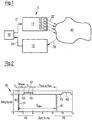
- a device 1 for the stimulation of neurons with a pathologically synchronous and oscillatory neuronal activity is shown schematically.
- the device 1 consists of a control unit 10, a stimulation unit 11 with one or more stimulation elements 12 and a measuring unit 13.
- the stimulation unit 11 contains, for example, four stimulation elements 12.
- the stimulation unit 11 can of course also have a different number of stimulation elements 12.
- the stimulation elements 12 may e.g. B. stimulation contact surfaces of one or more electrodes for application act on electrical stimuli to the neural tissue. If optically stimulated, z. B. optical fibers can be used as stimulation elements 12 to stimulate the neural tissue at the desired locations with light stimuli.
- the control unit 10 is coupled to the stimulation unit 11 and the measuring unit 13 and controls the stimulation unit 11 while the device 1 is operating. For this purpose, the control unit 10 generates control signals 21, which are received by the stimulation unit 11.
- the stimulation unit 11 is surgically implanted in the patient's body and uses the control signals 21 to generate one or more stimulation signals or stimuli 22, in particular electrical and / or optical stimulation signals 22, which are applied to the patient's tissue, in order to thereby generate neurons in a target area 30 stimulate in the patient's brain and / or spinal cord.
- the stimulation signals 22 are in particular designed to desynchronize the neurons with the pathologically synchronous and oscillatory activity when administered to the patient.
- the measuring unit 13 receives one or more measurement signals 23 measured on the patient, converts these, if necessary, into electrical signals 24 and feeds them to the control unit 10.
- the measuring unit 13 can be used to measure the neural activity in the stimulated target area 30 or in an area connected to the target area 30, the neural activity of this area correlating sufficiently closely with the neuronal activity of the target area 30.
- the stimulation effect achieved by the stimulation signals 22 can be monitored with the aid of the measuring unit 13.
- the measuring unit 13 contains one or more sensors, which in particular make it possible to record the amplitude of the pathological oscillatory neuronal activity.
- the sensors can be implanted in the patient's body.
- invasive sensors for example, epicortical electrodes, deep brain electrodes for measuring z.
- the depth electrodes for measuring the local field potentials can also be structurally combined or even identical to the electrodes used for the stimulation.
- the contacts of the electrodes can be placed in such a way that they can derive relevant neural feedback signals.
- non-invasive sensors can be used, e.g. B. chronically or intermittently used electroencephalography (EEG) - or electromyography (EMG) electrodes or magnetic encephalography (MEG) sensors.
- EEG electroencephalography
- EMG electromyography
- MEG magnetic encephalography
- the neuronal activity can also be determined by detecting characteristic movement patterns such as tremors, akinesis or epileptic seizures with the help of an accelerometer or gyroscope or indirectly by measuring the activation of the autonomic nervous system by measuring the skin resistance.
- the underlying currents can be calculated using inverse methods known to the person skilled in the art and used as the feedback modulation signals described below.
- the control unit 10 processes the signals 24, e.g. B. the signals 24 can be amplified and / or filtered. Furthermore, the control unit 10 generates a modulation signal from the signals 24 and thus from the measurement signal 23, with which the amplitude of a pulse train comprising a plurality of individual pulses is modulated.
- the control unit 10 controls the stimulation unit 11 in such a way that the at least one stimulation element 12 administers the amplitude-modulated pulse train to the tissue as the stimulation signal 22 in order to thereby stimulate the neurons in the target area 30.
- the individual pulses of the pulse train each consist of a first pulse component and a second pulse component following the first pulse component. One of the first pulse component and the second pulse component introduces charge into the tissue and the other pulse component takes charge from the tissue. Furthermore, a pause is maintained between the first pulse component and the second pulse component of the individual pulses.
- the control unit 10 can be a non-invasive unit, i. that is, during operation of the device 1, it is outside the patient's body and is not surgically implanted in the patient's body.
- the individual components of the device 1, in particular the control unit 10, the stimulation unit 11 and / or the measuring unit 13, can be structurally separate from one another.
- the device 1 can therefore also be understood as a system.
- the control unit 10 can have a processor, e.g. B. contain a microcontroller.
- the stimulation methods described herein can be stored as software code in a memory assigned to the control unit 10.
- the device 1 can be used in particular for the treatment of neurological or psychiatric disorders, e.g. B. Parkinson's disease, essential tremor, tremor due to multiple sclerosis and other pathological tremors, dystonia, epilepsy, depression, movement disorders, cerebellar disorders, obsessive-compulsive disorders, dementias, Alzheimer's disease, Tourette syndrome, autism, functional disorders after stroke, spasticity, sleep disorders, tinnitus , Schizophrenia, irritable bowel syndrome, addictive disorders, borderline personality disorder, attention deficit syndrome, attention deficit hyperactivity syndrome, gambling addiction, neuroses, feed addiction, Anorexia, eating disorders, burnout syndrome, fibromyalgia, migraines, cluster headache, general headache, neuralgia, ataxia, tic disorder or hypertension, as well as other diseases that are characterized by pathologically increased neuronal synchronization.
- neurological or psychiatric disorders e.g. B. Parkinson's disease, essential tremor,
- the aforementioned diseases can be caused by a disruption in the bioelectrical communication of neuron groups that are connected in specific circuits.
- a neuron population generates persistent pathological neural activity and possibly a pathological connectivity (network structure) associated with it.
- a large number of neurons synchronously form action potentials, i. that is, the neurons involved fire excessively synchronously.
- the diseased neuron population has an oscillatory neuronal activity, i. that is, the neurons fire rhythmically.
- the mean frequency of the abnormal rhythmic activity of the affected neuron groups is approximately in the range from 1 to 30 Hz, but can also be outside this range. In healthy people, however, the neurons fire qualitatively differently, e.g. B. in an uncorrelated manner.
- a section of a pulse train 35 is shown by way of example, from which a stimulation signal or stimulus 22 for stimulating the neurons in the target area 30 can be generated.
- Fig. 2 shows the pulse train 35 before performing the amplitude modulation.
- the pulse train 35 consists of a large number of individual pulses 40, which are repeated periodically in particular and of which in Fig. 2 two individual pulses 40 are shown as examples.
- Fig. 2 is the amplitude or the signal strength of the individual pulses 40, z. B. in normalized units, plotted against time in ms.
- Each of the individual pulses 40 consists of a first pulse component 41, a second pulse component 42 following the first pulse component 41 and a pause 43 lying between the first pulse component 41 and the second pulse component 42.
- the first pulse component 41 has a duration t 1
- the second pulse component 42 has a duration t 2
- the pause has a duration t pause .
- the first and the second pulse component 41, 42 are designed such that one of the two pulse components 41, 42 introduces charge into the tissue and the other pulse component takes charge from the tissue.
- the first pulse portion 41 introduces charge into the tissue and the second pulse portion 42 takes charge from the tissue.
- the first pulse portion 41 takes charge from the tissue and the second pulse portion 42 releases charge to the tissue.
- the amount of the amplitude of the first pulse portion 41 is greater than the amount of the amplitude of the second pulse portion 42.
- the duration t 2 of the second pulse portion 42 is longer than the duration t 1 of the first pulse portion 41.
- the two pulse portions 41, 42 are ideally so dimensioned that the charge that is transmitted through it is the same size for both pulse components 41, 42, ie that in Fig. 2 hatched areas 44 and 45, which are obtained by integrating the pulse components 41 and 42 over time, are of equal size.
- duration t 1 is introduced into the tissue as the tissue during ladungsbalancierenden stimulation phase of duration t 2 is removed by a single pulse 40th
- Such pulses are called charge-balanced pulses.
- the duration t 1 of the first pulse component 41 is in particular in the range between 1 ⁇ s and 450 ⁇ s. If electrical stimulation is involved, the individual pulses 40 can be current- or voltage-controlled pulses. The amplitude of the The first pulse component 41 can be up to 25 mA in the case of current-controlled pulses and up to 16 V in the case of voltage-controlled pulses.
- the amplitude of the individual pulse 40 is zero, i. that is, during pause 43, no charge is introduced into the tissue nor is charge removed from the tissue.
- the individual pulses 40 of the pulse train 35 are in particular identical and are applied periodically at a frequency f stim .
- the permanent application of a pulse train 35 with a frequency f stim of at least 100 Hz is referred to as high-frequency continuous stimulation.
- the pause 43 between the two pulse components 41, 42 of an individual pulse 40 contributes significantly to the success of the stimulation.
- the duration t pause of the pause 43 is at least 1 ms.
- the duration t pause of the pause 43 is in the range from 1 ms to 6 ms. It can further be provided that the duration t pause of the pause 43 is adapted to the frequency f stim with which the individual pulses 40 are applied repetitively within the pulse train 35. The greater the frequency f stim , the shorter the period length T stim . Thus, the maximum possible duration of the pause 43 under the secondary condition that t pause ⁇ t pulse-to-pulse applies, the smaller the greater the frequency f stim .
- control unit 10 can vary the duration t pause of the pause 43 until the synchronization of the stimulated neurons is minimal or falls below a predetermined threshold value.
- the pulse train 35 with the periodically occurring individual pulses 40 is preferably applied permanently, ie for a comparatively long period of time.
- the pulse train 35 is applied for longer than 30 minutes or 1 hour or 2 hours.
- the rectangular shape of the individual pulses 40 and in particular the first and second pulse components 41, 42 shown represents an ideal shape. Depending on the quality of the electronics producing the individual pulses 40, the ideal rectangular shape is deviated from.
- Individual pulses 40 shown with the first and second pulse components 41, 42 can also be referred to as individual stimuli 40 with first and second stimulus components 41, 42, which are applied within a periodic stimulus sequence. Furthermore, instead of first and second pulse components, one can speak of first and second phases.
- the amplitude of the pulse train 35 is modulated with a modulation signal which the control unit 10 generates from the measurement signal 23. Since the measurement signal 23 reproduces the pathologically synchronous neuronal activity of the stimulated neurons, feedback amplitude modulation is consequently carried out, i. H. an amplitude modulation with a feedback signal as a modulation signal.
- the feedback modulation signal which is referred to below as S (t), is also delayed and processed linearly or non-linearly compared to the measurement signal 23 received by the measuring unit 13.
- the measurement signal 23 is first preprocessed, e.g. B. amplified and / or bandpass filtered, the physiologically relevant frequency range being let through by the bandpass filter.
- a preprocessed measurement signal 23 recorded at a time t is to be referred to as x (t) below.
- I is the parameter of the stimulation intensity
- ⁇ indicates the time delay of the feedback modulation signal S (t) compared to the measurement signal 23 or the preprocessed measurement signal x (t). Then applies to the linear time-delayed feedback modulation signal S (t):
- S t I x t - ⁇ - x t
- the stimulation elements 12 deliver the stimulation signal 22 to the neuronal Tissue and stimulate the neurons with the pathologically synchronous neuronal activity in the target area 30.
- Z * (t) gives the complex conjugate of Z (t).
- the signal y (t), which represents the imaginary part of the signal Z (t) can be obtained from the signal x (t) by means of a Hilbert transformation.
- the signal y (t) can be generated from the signal x (t) by a time delay.
- the mean period T of the pathologically synchronous oscillatory neuronal activity of the stimulated neurons can be extracted from the measurement signal 23.
- the stimulation signal 22 can be generated by multiplying the signal H (t) of the pulse train 35 by the non-linear time-delayed feedback modulation signal S (t). Furthermore, instead of the complex modulation signal S (t), only the real part of this signal can be multiplied by the signal H (t) in order to obtain the stimulation signal 22.
- the following applies to the real part of the non-linear time-delayed feedback modulation signal S (t): re S t ix t - ⁇ x 2 t - y 2 t + 2 ⁇ ix t y t y t - ⁇
- 3 and 4 schematically show different electrical pulse trains, the amplitude of which was modulated with different feedback modulation signals S (t). 3 and 4 each contain a separate enlarged representation of the individual pulse 40 used in each case. It should be noted that in 3 and 4 for a simplified representation, the pauses 43 between the first pulse components 41 and the second pulse components 42 of the individual pulses 40 are not shown.
- the first pulse portion 41 is in each case an anodic, positive phase and the second pulse portion 42 is a cathodic, negative phase.
- Fig. 4 are the polarities of the two pulse components 41, 42 with respect to the pulse train 35 Fig. 3 interchanged so that the first pulse portion 41 is a cathodic phase and the second pulse portion 42 is an anodic phase.
- the individual pulses 40 are dimensioned even after the amplitude modulation with the feedback modulation signal S (t) such that the same amount of charge is introduced into the tissue during the actual stimulation phase by a single pulse 40 as is taken from the tissue during the charge-balancing stimulation phase ,
- a pulse train 35 inserts a pause 43 between the first pulse component 41 and the second pulse component 42 of the individual pulses 40 and modulates the amplitude of the pulse train 35 with the linear or non-linear time-delayed feedback stimulation signal S (t), a fully pronounced desynchronization is achieved , A significant improvement in the desynchronization is achieved with a duration t pause of pause 43 of 1 ms. Better values for the duration t pause of pause 43 amount to z. B. 5 ms.
- the high-frequency continuous stimulation with both linear and non-linear time-delayed feedback amplitude modulation and individual pulses with pauses between the pulse components are comparable with regard to the dependence of the desynchronization effect on the time delay.
- the non-linear variant is no longer clearly superior, as is the case with conventional time-delayed feedback stimulation.
- the technically easier to implement variant that is the high-frequency continuous stimulation with linear time-delayed feedback amplitude modulation and individual pulses with pauses between the pulse components, can be used.
- the particularly undelayed signal is also used. In comparison, it is easier to simply delay the signal component - as in the linear variant.
- control unit 10 varies the time delay ⁇ of the feedback modulation signal S (t) compared to the measurement signal 23 or the preprocessed measurement signal x (t).
- the variation of the time delay ⁇ can in particular continue until the synchronization of the stimulated neurons is minimal or falls below a predetermined threshold value.
- the optimal time delay ⁇ can e.g. B. in the range of 0.5 to 2.5 times or 1.5 to 2.5 times the mean period of the abnormal rhythmic activity of the affected neuron population.
- the time delay ⁇ can be in a range from 5 ms to 2 s.
- the optimal value for the time delay ⁇ can also - z. B. caused by internal time delays in the neuron population and thus interacting neuron populations - differ greatly.
- the dependence of the success of the stimulation on the time delay ⁇ is shown by those explained below Figures 11 and 14 ,
- the time delays associated with areas of local minimums of the synchronization typically repeat after a multiple of the mean period.
- the time delays ⁇ opt + T mean or ⁇ opt + 2 T mean are also suitable for a pronounced desynchronization, T mean denoting the mean period of the pathological rhythmic activity of the affected neuron population.
- the following calibration procedure can therefore be carried out:
- the mean period T average is determined or a value known to the person skilled in the art is taken as the starting point. The latter is possible because the pathological oscillatory activity is in typical frequency bands.
- the parameter ⁇ is allowed to grow slowly until a pronounced desynchronization occurs, ie, the synchronization of the stimulated ones Neurons reach a local minimum or fall below a predetermined threshold.
- a further increase then leads to a decrease in desynchronization.
- the intensity, ie in particular the amplitude of the stimulation can be slowly increased at the previously determined fixed value for ⁇ in order to be able to achieve an even more efficient desynchronization.
- the increase in intensity can e.g. B. continue until the synchronization of the stimulated neurons reaches a further local minimum or falls below a further predetermined threshold value.
- Fig. 5 schematically shows a device 50 for invasive electrical stimulation of neurons with a pathologically synchronous and oscillatory neuronal activity according to an embodiment of the invention.
- the device 50 comprises two deep brain electrodes 51, 52, which are implanted in the patient's brain and are connected to a connector 54 via cables 53.
- the connector 54 is in turn connected to a control unit 56 via a cable 55.
- the control unit 56 generates the stimulation signals based on the measured feedback signals.
- the stimulation signals can be generated separately for both brain electrodes 51, 52. However, it can also be stimulated via one of the two brain electrodes 51, 52 and measured via the other brain electrode.
- the device 50 can have the function of the device 1 described above.
- Fig. 6 schematically shows a further device 60 for invasive electrical stimulation of neurons with a pathologically synchronous and oscillatory neuronal activity according to a further embodiment of the invention.
- the device 60 comprises two implanted deep brain electrodes 61, 62.
- the device 60 further comprises a control unit 63 implanted in the borehole, which is connected directly to the brain electrode 62.
- the brain electrode 61 is connected to the control unit 63 via a cable 64.
- the stimulation signals can be generated separately for both brain electrodes 61, 62. However, it can also be stimulated via one of the two brain electrodes 61, 62 and measured via the other brain electrode.
- the device 60 can have the same functions as the device 1.
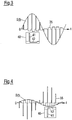
- Fig. 7 schematically shows a multi-channel electrode 70, which serves as a stimulation unit 11 and has a plurality of electrically conductive contacts or stimulation contact surfaces 71 arranged in an array, which represent the stimulation elements 12.
- the contacts 71 can be individually controllable, so that a desired electrical stimulation signal 22 can be applied via each contact 71.
- the stimulation signal 22 can be applied spatially weighted according to anatomical and / or physiological boundary conditions via a plurality of contacts 71.
- the contacts 71 can also be used to measure neuronal activity. Measuring or stimulation contacts 71 are shown in Fig. 7 each illustrated by dark panes. For example, measurements or stimulations are carried out over different groups of contacts 71.
- Fig. 8 schematically shows a multi-channel electrode 80, which serves as a stimulation unit 11 and has a multiplicity of ring-shaped, electrically conductive contacts or stimulation contact surfaces 81, which represent the stimulation elements 12. For example, measurements are carried out or stimulated via contacts 81 marked in dark, while contacts 81 are neither measured nor stimulated via contacts 81 marked in white.
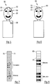
- Fig. 9 shows schematically multi-channel electrodes 90, 91, each of which has a multiplicity of electrically conductive contacts 92 arranged in an array.
- the multichannel electrodes 90, 91 stimulate two interacting neuron populations 93, 94 in the target area 30.
- the multi-channel electrode 90 is placed directly on the target area 30 for direct stimulation of the neuron populations 93, 94. In this way, the somata, axons and dendrites of the neuron populations 93, 94 can be stimulated directly.
- the neuron populations 93, 94 are stimulated with the dark fill via the contacts 92 assigned to the neuron populations 93, 94.
- a group of contacts 92 is assigned to each of the neuron populations 93, 94.
- a measurement signal which reflects the neuronal activity of the stimulated neuron populations 93, 94, can be derived via the multi-channel electrode 90.
- the multi-channel electrode 91 is not placed directly on the target area 30, rather afferent fibers 95, which lead to and / or arise from the neuron populations 93, 94, are stimulated.
- groups 96, 97 are each formed from a plurality of contacts 92, and groups 96, 97 indirectly stimulate the neuron populations 93, 94 via the afferent fibers 95.
- the contacts 92 of the groups 96, 97 are in Fig. 9 shown with a dark fill.
- Implantable stimulation units 11 for the optical stimulation of neuronal tissue are known.
- a light source such as. B. a laser, a laser diode or an LED, generate a light beam that is distributed with the aid of a light coupling to the inputs of a fiber bundle consisting of several optical fibers.
- a control unit 10 gives z. B. before, at which time a single light pulse or a train of light pulses is coupled into which fiber of the fiber bundle.
- the decoupling points of the individual fibers of the fiber bundle, i.e. H. the ends of the fibers may be at different locations in the target area 30 in the patient's brain and / or spinal cord.
- the light stimulates different locations of the target area 30 in a time sequence predetermined by the control unit 10.
- implantable stimulation units 11 that are suitable for direct optical stimulation of neuronal tissue can also be used.
- optical stimulation signals 22 the light intensity of a pulse train is amplitude-modulated with the feedback modulation signal S (t).
- Fig. 10 shown by the rate of fire of a neuron population.
- the rate of fire indicates the relative number of neurons firing at a given time.
- the rate of fire of the neurons is plotted against time.
- the rhythmic firing of the neurons of the pathologically active neuron population before stimulation is shown.
- the synchronization of the neurons becomes significant through continuous high-frequency stimulation with a non-linear, time-delayed feedback amplitude modulation reduced, like the two lower representations of Fig. 10 demonstrate.
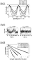
- Fig. 11 shows the degree of synchronization of a neuron population with a pathologically synchronous and oscillatory neuronal activity as a function of the time delay ⁇ for high-frequency continuous stimulation with a non-linear time-delayed feedback amplitude modulation.
- the time delay ⁇ determines the time period by which the feedback modulation signal S (t) is delayed compared to the measurement signal x (t).
- the simulation was carried out for single pulses with pauses t pause of 0, 2 or 5 ms and fixed stimulation intensity I.
- the horizontal dashed line in Fig. 11 indicates the degree of synchronization of the neuron population before stimulation.
- Fig. 11 it can be seen that for certain sub-areas of the time delay ⁇ a significantly more effective desynchronization of the neuron population can be achieved if a pause is maintained between the pulse components of the individual pulses.
- the desynchronization effect achieved by the pause between the pulse components of the individual pulses also increases with an increasing stimulation intensity I.
- This property is in Fig. 12 shown in which the degree of synchronization of the stimulated neuron population against the stimulation intensity I is plotted for a fixed time delay ⁇ of 40 ms and values for the pause t pause of 0, 1, 2 or 5 ms.
- high-frequency continuous stimulation with a non-linear, time-delayed feedback amplitude modulation without a pause between the individual pulses only desynchronizes the neuron population to a certain degree.
- the same stimulation with a pause between the individual pulses gives much better results.
- a higher stimulation intensity I leads to a stronger desynchronization of the neuron population.
- Fig. 13 The effectiveness of the stimulation described herein is in Fig. 13 shown in which the degree of synchronization is plotted against the amount of stimulation administered.
- the amount of stimulation administered is given by the amplitude of the feedback modulation signal S (t), as exemplified in 3 and 4 is shown.
- the in Fig. 13 The values shown are based on a simulation of a high-frequency continuous stimulation with a non-linear time-delayed feedback amplitude modulation with a fixed time delay ⁇ of 150 ms and pauses t pause of 0, 1, 2 or 5 ms.
- Fig. 13 shows that stimulation with a longer pause t pause requires a smaller amount of the stimulation administered to achieve the same desynchronization effect as a stimulation with a shorter pause t pause .
- Fig. 14 the degree of synchronization of a neuron population with a pathologically synchronous and oscillatory neuronal activity as a function of the time delay ⁇ for high-frequency continuous stimulation with a linear time-delayed feedback amplitude modulation.
- the simulation was carried out for single pulses with pauses t pause of 0, 1, 2 or 5 ms and fixed stimulation intensity I.
- the horizontal dashed line in Fig. 14 indicates the degree of synchronization of the neuron population before stimulation.
- a comparison with the in Fig. 11 Results shown shows that the linear time-delayed feedback amplitude modulation of the non-linear time-delayed feedback amplitude modulation for certain values of the time delay ⁇ with otherwise identical parameters is superior.
- Fig. 15 the rate of fire of the neurons is plotted against the time, which is brought about by high-frequency continuous stimulation with linear, time-delayed feedback amplitude modulation and individual pulses with or without a pause t pause between the pulse components.
- stimulation with individual pulses that have a pause t pause of 5 ms between the first and second pulse components is clearly superior to stimulation with individual pulses, the first and second pulse components of which follow one another directly ,
- Fig. 16 the degree of synchronization is plotted against the amount of stimulation administered, which is achieved with high-frequency continuous stimulation with linear time-delayed feedback amplitude modulation with a fixed time delay ⁇ of 70 ms and pauses t pause of 0, 1, 2 or 5 ms leaves.
- stimulation with a longer pause t pause leads to the same desynchronization effect as stimulation with a shorter pause t pause , but with a higher amount of the stimulation administered.
Description
Die Erfindung betrifft eine Vorrichtung zur effektiven, invasiven und amplitudenmodulierten Neurostimulation.The invention relates to a device for effective, invasive and amplitude-modulated neurostimulation.
Bei Patienten mit neurologischen oder psychiatrischen Erkrankungen, z. B. Morbus Parkinson, essentiellem Tremor, Dystonie oder Zwangserkrankungen, sind Nervenzellverbände in umschriebenen Bereichen des Gehirns, z. B. des Thalamus und der Basalganglien krankhaft, z. B. übersteigert synchron, aktiv. In diesem Fall bildet eine große Anzahl von Neuronen synchron Aktionspotentiale aus, d. h., die beteiligten Neuronen feuern übermäßig synchron. Beim Gesunden hingegen feuern die Neuronen in diesen Hirngebieten qualitativ anders, z. B. auf unkorrelierte Weise.In patients with neurological or psychiatric disorders, e.g. B. Parkinson's disease, essential tremor, dystonia or obsessive-compulsive disorders are nerve cell associations in circumscribed areas of the brain, e.g. B. the thalamus and basal ganglia pathological, e.g. B. exaggerated synchronously, actively. In this case, a large number of neurons synchronously form action potentials, i. that is, the neurons involved fire excessively synchronously. In the healthy, however, the neurons in these brain areas fire qualitatively differently, e.g. B. in an uncorrelated manner.
Beim Morbus Parkinson verändert die pathologisch synchrone Aktivität die neuronale Aktivität in anderen Hirngebieten, z. B. in Arealen der Großhirnrinde wie dem primär motorischen Cortex. Dabei zwingt die pathologisch synchrone Aktivität im Bereich des Thalamus und der Basalganglien beispielsweise den Großhirnrindenarealen ihren Rhythmus auf, so dass schließlich die von diesen Arealen gesteuerten Muskeln pathologische Aktivität, z. B. ein rhythmisches Zittern (Tremor), entfalten.In Parkinson's disease, the pathologically synchronous activity changes the neuronal activity in other brain areas, e.g. B. in areas of the cerebral cortex such as the primary motor cortex. The pathologically synchronous activity in the area of the thalamus and the basal ganglia, for example, imposes their rhythm on the areas of the cerebral cortex, so that the muscles controlled by these areas ultimately have pathological activity, e.g. B. develop a rhythmic tremor (tremor).
Zur Behandlung von medikamentös nicht hinreichend behandelbaren Parkinsonpatienten wird die tiefe Hirnstimulation eingesetzt. Hierbei werden Tiefenelektroden in speziellen Hirngebieten, z. B. im Nucleus subthalamicus, implantiert. Zur Linderung der Symptome wird über die Tiefenelektroden eine elektrische Reizung durchgeführt. Bei der Standard-Hochfrequenz-Stimulation zur Behandlung der Parkinsonschen Erkrankung wird eine sogenannte Hochfrequenz-Dauerreizung bei Frequenzen von über 100 Hz durchgeführt. Diese Behandlungsart hat keine lang anhaltenden therapeutischen Effekte (vgl.
Bei anderen Erkrankungen, z. B. bei medikamentös nicht ausreichend behandelbaren Epilepsien, werden neben Tiefenelektroden auch andere, z. B. epikortikale oder epidurale Elektroden, implantiert. Bei weiteren Erkrankungen, z. B. chronischen Schmerz-Syndromen, ist es üblich, nicht nur mittels Tiefenelektroden im Gehirn, sondern auch mittels z. B. epiduralen Elektroden das Rückenmark zu reizen. Anders als die CR-Stimulation haben die meisten anderen Stimulationsarten keine lang anhaltenden therapeutischen Effekte.With other diseases, e.g. B. epilepsy that cannot be adequately treated with medication, in addition to deep electrodes, other z. B. epicortical or epidural electrodes implanted. For other diseases, e.g. B. chronic pain syndromes, it is common not only by means of deep electrodes in the brain, but also by means of z. B. epidural electrodes to irritate the spinal cord. Unlike CR stimulation, most other types of stimulation do not have long-lasting therapeutic effects.
Therapeutische Effekte können auch durch direkte Stimulation des Hirngewebes bzw. Rückenmarks mit Licht, z. B. über implantierte Lichtleiter, erzielt werden. Hierbei können auch unterschiedliche raum-zeitliche Stimulationsmuster, wie z. B. die CR-Stimulation, zur Anwendung kommen.Therapeutic effects can also be achieved by direct stimulation of the brain tissue or spinal cord with light, e.g. B. via implanted light guides can be achieved. Different spatial-temporal stimulation patterns, such as e.g. B. CR stimulation, are used.
Die Wirkung der CR-Stimulation kann durch eine ungünstige Wahl der Stimulationsparameter, insbesondere der CR-Stimulationsfrequenz und der Stimulationsintensität im Sinne der Amplitude der Einzelreize und/oder der Dauer der Einzelreize, deutlich vermindert bzw. sogar unterbunden werden. Falsch bzw. sub-optimal gewählte Parameter können den Stimulationserfolg schwächen oder sogar vollständig unterbinden. Es ist somit wichtig, die Stimulationsparameter zu kalibrieren. Da Parameter des stimulierten Gewebes zeitlichen Schwankungen unterworfen sind, ist eine in hinreichenden zeitlichen Abständen erfolgende Kalibration notwendig. Da derartige Schwankungen in einer nicht vorhersehbaren Weise auftreten können, ist in einem "open loop"-Modus die Kalibration vergleichsweise häufig durchzuführen, und/oder es sind Feedback-Signale, d. h. Rückkopplungssignale, in einem "closed loop"-Modus abzuleiten, welche die Notwendigkeit der Re-Kalibration, z. B. im Sinne des Überschreitens einer tolerablen neuronalen Synchronisation, anzuzeigen vermögen.The effect of the CR stimulation can be significantly reduced or even prevented by an unfavorable choice of the stimulation parameters, in particular the CR stimulation frequency and the stimulation intensity in terms of the amplitude of the individual stimuli and / or the duration of the individual stimuli. Incorrectly or sub-optimally selected parameters can weaken the stimulation success or even completely prevent it. It is therefore important to calibrate the stimulation parameters. Since parameters of the stimulated tissue are subject to fluctuations in time, a calibration that takes place at sufficient time intervals is necessary. Since such fluctuations can occur in an unpredictable manner, the calibration must be carried out comparatively frequently in an "open loop" mode, and / or feedback signals, i. H. Derive feedback signals in a "closed loop" mode, indicating the need for re-calibration, e.g. B. in the sense of exceeding a tolerable neural synchronization.
Aus diesem Grund wurden Stimulationsmethoden entwickelt, welche mit deutlich weniger Stimulationsparametern als die CR-Stimulation auskommen, z. B. die lineare zeitverzögerte Feedback-Stimulation (vgl.
Sowohl die herkömmliche lineare zeitverzögerte Feedback-Stimulation als auch die herkömmliche nicht-lineare zeitverzögerte Feedback-Stimulation sind in ihrer Wirksamkeit stark begrenzt, da bei therapeutisch wirksamen Stimulationsstärken der Ladungseintrag pro Halbschwingung typischerweise die zulässigen Obergrenzen zur Vermeidung von Gewebeschäden deutlich übersteigt (vgl.
Der Erfindung liegt die Aufgabe zugrunde, eine Vorrichtung zur Stimulation von Neuronen anzugeben, mit der sich im Vergleich zum Stand der Technik die Reizung deutlich weniger fehleranfällig und robuster durchführen und der gewünschte Desynchronisationseffekt ohne aufwändige Kalibration erzielen lässt.The invention is based on the object of specifying a device for stimulating neurons with which the stimulation can be carried out significantly less prone to errors and more robustly in comparison with the prior art and the desired desynchronization effect can be achieved without complex calibration.
Die der Erfindung zugrunde liegende Aufgabenstellung wird durch die Merkmale der unabhängigen Ansprüche gelöst. Vorteilhafte Weiterbildungen und Ausgestaltungen der Erfindung sind in den Unteransprüchen angegeben.The problem underlying the invention is solved by the features of the independent claims. Advantageous further developments and refinements of the invention are specified in the subclaims.
Die Erfindung wird nachfolgend in beispielhafter Weise unter Bezugnahme auf die Zeichnungen näher erläutert. In diesen zeigen:
- Fig. 1
- eine schematische Darstellung einer Vorrichtung zur Desynchronisierung von Neuronen mit einer krankhaft synchronen und oszillatorischen neuronalen Aktivität gemäß einer Ausgestaltung;
- Fig. 2
- eine schematische Darstellung eines Pulszugs mit Einzelpulsen, die eine Pause zwischen einem ersten Pulsanteil und einem dem ersten Pulsanteil nachfolgenden zweiten Pulsanteil aufweisen;
- Fig. 3 und 4
- schematische Darstellungen von Pulszügen, deren Amplitude mit verschiedenen Modulationssignalen moduliert wurde;
- Fig. 5 und 6
- schematische Darstellungen von Vorrichtungen zur Desynchronisierung von Neuronen mit einer krankhaft synchronen und oszillatorischen neuronalen Aktivität mittels elektrischer Stimulationssignale gemäß weiteren Ausgestaltungen;
- Fig. 7
- eine schematische Darstellung einer Vielkanal-Elektrode;
- Fig. 8
- eine schematische Darstellung einer Mehrkanal-Elektrode;
- Fig. 9
- eine schematische Darstellung einer Vielkanal-Elektrode zur direkten Stimulation eines Zielareals und/oder Ableitung von Messsignalen und einer weiteren Vielkanal-Elektrode zur indirekten Stimulation des Zielareals;
- Fig. 10
bis 13 - Diagramme mit Simulationsergebnissen für eine Hochfrequenz-Dauerstimulation mit einer nicht-linearen zeitverzögerten Feedback-Amplitudenmodulation und Einzelpulsen mit und ohne Pausen zwischen aufeinanderfolgenden Pulsanteilen; und
- Fig. 14 bis 16
- Diagramme mit Simulationsergebnissen für eine Hochfrequenz-Dauerstimulation mit einer linearen zeitverzögerten Feedback-Amplitudenmodulation und Einzelpulsen mit und ohne Pausen zwischen aufeinanderfolgenden Pulsanteilen.
- Fig. 1
- a schematic representation of a device for desynchronizing neurons with a pathologically synchronous and oscillatory neuronal activity according to one embodiment;
- Fig. 2
- a schematic representation of a pulse train with individual pulses which have a pause between a first pulse component and a second pulse component following the first pulse component;
- 3 and 4
- schematic representations of pulse trains, the amplitude of which has been modulated with different modulation signals;
- 5 and 6
- schematic representations of devices for the desynchronization of neurons with a pathologically synchronous and oscillatory neuronal activity by means of electrical stimulation signals according to further embodiments;
- Fig. 7
- a schematic representation of a multi-channel electrode;
- Fig. 8
- a schematic representation of a multi-channel electrode;
- Fig. 9
- a schematic representation of a multi-channel electrode for direct stimulation of a target area and / or derivation of measurement signals and a further multi-channel electrode for indirect stimulation of the target area;
- 10 to 13
- Diagrams with simulation results for a high-frequency continuous stimulation with a non-linear time-delayed feedback amplitude modulation and individual pulses with and without pauses between successive pulse components; and
- 14 to 16
- Diagrams with simulation results for high-frequency continuous stimulation with linear time-delayed feedback amplitude modulation and single pulses with and without pauses between successive pulse components.
In
In der in
Die Steuereinheit 10 ist mit der Stimulationseinheit 11 und der Messeinheit 13 gekoppelt und führt während des Betriebs der Vorrichtung 1 eine Steuerung der Stimulationseinheit 11 durch. Dazu erzeugt die Steuereinheit 10 Steuersignale 21, die von der Stimulationseinheit 11 entgegengenommen werden.The
Die Stimulationseinheit 11 wird operativ in den Körper des Patienten implantiert und erzeugt anhand der Steuersignale 21 ein oder mehrere Stimulationssignale bzw. Reize 22, insbesondere elektrische und/oder optische Stimulationssignale 22, die an das Gewebe des Patienten appliziert werden, um damit Neuronen in einem Zielareal 30 im Gehirn und/oder Rückenmark des Patienten zu stimulieren. Die Stimulationssignale 22 sind insbesondere dazu ausgelegt, bei einer Verabreichung an den Patienten die Neuronen mit der krankhaft synchronen und oszillatorischen Aktivität zu desynchronisieren.The
Die Messeinheit 13 nimmt ein oder mehrere am Patienten gemessene Messsignale 23 auf, wandelt diese gegebenenfalls in elektrische Signale 24 um und führt sie der Steuereinheit 10 zu. Insbesondere kann mittels der Messeinheit 13 die neuronale Aktivität in dem stimulierten Zielareal 30 oder einem mit dem Zielareal 30 verbundenen Gebiet gemessen werden, wobei die neuronale Aktivität dieses Gebiets mit der neuronalen Aktivität des Zielgebiets 30 hinreichend eng korreliert. Mittels der Messeinheit 13 kann auch eine nicht-neuronale, z. B. muskuläre Aktivität oder die Aktivierung des autonomen Nervensystems, gemessen werden, sofern diese mit der neuronalen Aktivität des Zielgebiets 30 hinreichend eng korreliert sind. Weiterhin kann der durch die Stimulationssignale 22 erzielte Stimulationseffekt mit Hilfe der Messeinheit 13 überwacht werden.The measuring
Die Messeinheit 13 enthält einen oder mehrere Sensoren, die es insbesondere ermöglichen, die Amplitude der pathologischen oszillatorischen neuronalen Aktivität aufzunehmen.The measuring
Die Sensoren können in den Körper des Patienten implantiert sein. Als invasive Sensoren können beispielsweise epikortikale Elektroden, Tiefenhirnelektroden zur Messung von z. B. lokalen Feldpotentialen, sub- oder epidurale Hirnelektroden, subkutane EEG-Elektroden und sub- oder epidurale Rückenmarkselektroden dienen. Die Tiefenelektroden zur Messung der lokalen Feldpotentiale können auch baulich vereint oder sogar identisch mit den für die Stimulation verwendeten Elektroden sein. Die Kontakte der Elektroden können derart platziert werden, dass sie relevante neuronale Feedback-Signale ableiten können.The sensors can be implanted in the patient's body. As invasive sensors, for example, epicortical electrodes, deep brain electrodes for measuring z. B. local field potentials, sub- or epidural brain electrodes, subcutaneous EEG electrodes and sub- or epidural spinal cord electrodes are used. The depth electrodes for measuring the local field potentials can also be structurally combined or even identical to the electrodes used for the stimulation. The contacts of the electrodes can be placed in such a way that they can derive relevant neural feedback signals.
Alternativ können nicht-invasive Sensoren eingesetzt werden, z. B. chronisch oder intermittent genutzte Elektroenzephalographie (EEG)- oder Elektromyographie (EMG)-Elektroden oder Magnetenzephalographie (MEG)-Sensoren. Die neuronale Aktivität kann auch durch Detektion charakteristischer Bewegungsmuster wie Tremor, Akinese oder epileptische Anfälle mit Hilfe eines Akzelerometers oder Gyroskops oder indirekt durch Messung der Aktivierung des autonomen Nervensystems mittels Messung des Hautleitwiderstands ermittelt werden. Im Falle von LFP-, EEG- und/oder MEG-Signalen können mittels dem Fachmann bekannten Inversmethoden die zugrunde liegenden Ströme berechnet und als die weiter unten beschriebenen Feedback-Modulationssignale verwendet werden.Alternatively, non-invasive sensors can be used, e.g. B. chronically or intermittently used electroencephalography (EEG) - or electromyography (EMG) electrodes or magnetic encephalography (MEG) sensors. The neuronal activity can also be determined by detecting characteristic movement patterns such as tremors, akinesis or epileptic seizures with the help of an accelerometer or gyroscope or indirectly by measuring the activation of the autonomic nervous system by measuring the skin resistance. In the case of LFP, EEG and / or MEG signals, the underlying currents can be calculated using inverse methods known to the person skilled in the art and used as the feedback modulation signals described below.
Die Steuereinheit 10 verarbeitet die Signale 24, z. B. können die Signale 24 verstärkt und/oder gefiltert werden. Ferner erzeugt die Steuereinheit 10 aus den Signalen 24 und damit aus dem Messsignal 23 ein Modulationssignal, mit dem die Amplitude eines eine Vielzahl von Einzelpulsen umfassenden Pulszugs moduliert wird. Die Steuereinheit 10 steuert die Stimulationseinheit 11 derart an, dass das mindestens eine Stimulationselement 12 den amplitudenmodulierten Pulszug als das Stimulationssignal 22 dem Gewebe verabreicht, um damit die Neuronen in dem Zielgebiet 30 zu stimulieren. Die Einzelpulse des Pulszugs bestehen jeweils aus einem ersten Pulsanteil und einem dem ersten Pulsanteil nachfolgenden zweiten Pulsanteil. Einer von dem ersten Pulsanteil und dem zweiten Pulsanteil bringt Ladung in das Gewebe ein und der andere Pulsanteil entnimmt Ladung aus dem Gewebe. Ferner wird zwischen dem ersten Pulsanteil und dem zweiten Pulsanteil der Einzelpulse jeweils eine Pause eingehalten.The
Die Steuereinheit 10 kann eine nicht-invasive Einheit sein, d. h., während des Betriebs der Vorrichtung 1 befindet sie sich außerhalb des Körpers des Patienten und wird nicht operativ in den Körper des Patienten implantiert.The
Die einzelnen Komponenten der Vorrichtung 1, insbesondere die Steuereinheit 10, die Stimulationseinheit 11 und/oder die Messeinheit 13, können baulich voneinander getrennt sein. Die Vorrichtung 1 kann daher auch als System aufgefasst werden. Zur Durchführung ihrer Aufgaben kann die Steuereinheit 10 einen Prozessor, z. B. einen Mikrocontroller, enthalten. Die hierin beschriebenen Stimulationsverfahren können als Software-Code in einem der Steuereinheit 10 zugeordneten Speicher abgelegt sein.The individual components of the
Die Vorrichtung 1 kann insbesondere zur Behandlung von neurologischen oder psychiatrischen Erkrankungen eingesetzt werden, z. B. Morbus Parkinson, essentiellem Tremor, Tremor infolge von Multipler Sklerose sowie anderen pathologischen Tremores, Dystonie, Epilepsie, Depression, Bewegungsstörungen, Kleinhirnerkrankungen, Zwangserkrankungen, Demenzerkrankungen, Morbus Alzheimer, Tourette-Syndrom, Autismus, Funktionsstörungen nach Schlaganfall, Spastik, Tinnitus, Schlafstörungen, Schizophrenie, Reizdarm-Syndrom, Suchterkrankungen, Borderline-Persönlichkeitsstörung, Aufmerksamkeits-Defizit-Syndrom, Aufmerksamkeits-Defizit-Hyperaktivitäts-Syndrom, Spielsucht, Neurosen, Fresssucht, Magersucht, Essstörungen, Burnout-Syndrom, Fibromyalgie, Migräne, Cluster-Kopfschmerz, allgemeiner Kopfschmerz, Neuralgie, Ataxie, Tic-Störung oder Hypertonie, sowie weiteren Erkrankungen, die durch krankhaft gesteigerte neuronale Synchronisation gekennzeichnet sind.The
Die vorstehend genannten Krankheiten können durch eine Störung der bioelektrischen Kommunikation von Neuronenverbänden, die in spezifischen Schaltkreisen zusammengeschlossen sind, verursacht werden. Hierbei generiert eine Neuronenpopulation anhaltend krankhafte neuronale Aktivität und möglicherweise eine damit verbundene krankhafte Konnektivität (Netzwerkstruktur). Dabei bildet eine große Anzahl von Neuronen synchron Aktionspotentiale aus, d. h., die beteiligten Neuronen feuern übermäßig synchron. Hinzu kommt, dass die kranke Neuronenpopulation eine oszillatorische neuronale Aktivität aufweist, d. h., die Neuronen feuern rhythmisch. Im Fall von neurologischen oder psychiatrischen Erkrankungen liegt die mittlere Frequenz der krankhaften rhythmischen Aktivität der betroffenen Neuronenverbände etwa im Bereich von 1 bis 30 Hz, kann aber auch außerhalb dieses Bereichs liegen. Bei gesunden Menschen feuern die Neuronen hingegen qualitativ anders, z. B. auf unkorrelierte Weise.The aforementioned diseases can be caused by a disruption in the bioelectrical communication of neuron groups that are connected in specific circuits. Here, a neuron population generates persistent pathological neural activity and possibly a pathological connectivity (network structure) associated with it. A large number of neurons synchronously form action potentials, i. that is, the neurons involved fire excessively synchronously. In addition, the diseased neuron population has an oscillatory neuronal activity, i. that is, the neurons fire rhythmically. In the case of neurological or psychiatric disorders, the mean frequency of the abnormal rhythmic activity of the affected neuron groups is approximately in the range from 1 to 30 Hz, but can also be outside this range. In healthy people, however, the neurons fire qualitatively differently, e.g. B. in an uncorrelated manner.
In
Der Pulszug 35 besteht aus einer Vielzahl von Einzelpulsen 40, die sich insbesondere periodisch wiederholen und von denen in
Jeder der Einzelpulse 40 besteht aus einem ersten Pulsanteil 41, einem dem ersten Pulsanteil 41 nachfolgenden zweiten Pulsanteil 42 und einer zwischen dem ersten Pulsanteil 41 und dem zweiten Pulsanteil 42 liegenden Pause 43. Der erste Pulsanteil 41 hat eine Dauer t1, der zweite Pulsanteil 42 hat eine Dauer t2 und die Pause hat eine Dauer tPause.Each of the
Der erste und der zweite Pulsanteil 41, 42 sind derart ausgestaltet, dass einer von den beiden Pulsanteilen 41, 42 Ladung in das Gewebe einbringt und der andere Pulsanteil Ladung dem Gewebe entnimmt. In der in
Der Betrag der Amplitude des ersten Pulsanteils 41 ist größer als der Betrag der Amplitude des zweiten Pulsanteils 42. Dafür ist die Dauer t2 des zweiten Pulsanteils 42 länger als die Dauer t1 des ersten Pulsanteils 41. Die beiden Pulsanteile 41, 42 sind idealerweise so dimensioniert, dass die Ladung, die durch sie übertragen wird, bei beiden Pulsanteilen 41, 42 gleich groß ist, d. h., die in
Die Dauer t1 des ersten Pulsanteils 41 liegt insbesondere im Bereich zwischen 1 µs und 450 µs. Sofern es sich um eine elektrische Stimulation handelt, können die Einzelpulse 40 strom- oder spannungskontrollierte Pulse sein. Die Amplitude des ersten Pulsanteils 41 kann im Fall von stromkontrollierten Pulsen bis zu 25 mA und im Fall von spannungskontrollierten Pulsen bis zu 16 V betragen.The duration t 1 of the
Während der zwischen dem ersten Pulsanteil 41 und dem zweiten Pulsanteil 42 liegenden Pause 43 ist die Amplitude des Einzelpulses 40 gleich Null, d. h., während der Pause 43 wird weder Ladung in das Gewebe eingebracht noch wird dem Gewebe Ladung entnommen.During the
Die Einzelpulse 40 des Pulszugs 35 sind insbesondere identisch und werden periodisch mit einer Frequenz fstim appliziert. Die Frequenz fstim, mit welcher die Einzelpulse 40 innerhalb des Pulszugs 35 repetitiv appliziert werden, beträgt insbesondere mindestens 100 Hz, beispielsweise liegt die Frequenz fstim im Bereich von 100 bis 200 Hz. Die Frequenz fstim kann aber auch noch höhere Werte annehmen. In
Während der Zeit tPuls-zu-Puls zwischen zwei innerhalb des Pulszugs 35 direkt aufeinanderfolgenden Einzelpulsen 40, d. h., zwischen dem Ende des zweiten Pulsanteils 42 eines Einzelpulses 40 und dem Beginn des ersten Pulsanteils 41 des direkt nachfolgenden Einzelpulses 40, wird nicht stimuliert, d. h., die Amplitude des Pulszugs 35 beträgt während der Zeit tPuls-zu-Puls Null. Es kann vorgesehen sein, dass die Zeit tPuls-zu-Puls zwischen zwei direkt aufeinanderfolgenden Einzelpulsen 40 länger ist als die Dauer tPause der Pause 43 zwischen dem ersten und dem zweiten Pulsanteil 41, 42 eines Einzelpulses 40. Es wird daraufhin gewiesen, dass sich die Zeit tPuls-zu-Puls folgendermaßen berechnet: ![]()
![]()
Wie weiter unten erläutert wird, trägt die Pause 43 zwischen den beiden Pulsanteilen 41, 42 eines Einzelpulses 40 wesentlich zum Stimulationserfolg bei. Gemäß einer Ausgestaltung beträgt die Dauer tPause der Pause 43 mindestens 1 ms. Gemäß einer weiteren Ausgestaltung liegt die Dauer tPause der Pause 43 im Bereich von 1 ms bis 6 ms. Weiterhin kann vorgesehen sein, dass die Dauer tPause der Pause 43 angepasst ist an die Frequenz fstim, mit der die Einzelpulse 40 innerhalb des Pulszugs 35 repetitiv appliziert werden. Je größer die Frequenz fstim ist, desto kürzer ist die Periodenlänge Tstim. Somit wird die maximal mögliche Dauer der Pause 43 unter der Nebenbedingung, dass tPause < tPuls-zu-Puls gilt, desto kleiner, je größer die Frequenz fstim wird.As will be explained further below, the
Weiterhin kann die Steuereinheit 10 die Dauer tPause der Pause 43 variieren, bis die Synchronisation der stimulierten Neuronen minimal ist oder einen vorgegebenen Schwellwert unterschreitet.Furthermore, the
Der Pulszug 35 mit den periodisch auftretenden Einzelpulsen 40 wird vorzugsweise dauerhaft appliziert, d. h. während eines vergleichsweise langen Zeitraums. Z. B. wird der Pulszug 35 länger als 30 Minuten oder 1 Stunde oder 2 Stunden appliziert. Während der Applikation des Pulszugs 35 werden außer den oben beschriebenen Pausen mit den Längen tPause und tPuls-zu-Puls vorzugsweise keine weiteren Pausen eingehalten.The
Die in
Die in
Die Amplitude des Pulszugs 35 wird wie oben beschrieben mit einem Modulationssignal moduliert, welches die Steuereinheit 10 aus dem Messsignal 23 erzeugt. Da das Messsignal 23 die pathologisch synchrone neuronale Aktivität der stimulierten Neuronen wiedergibt, wird folglich eine Feedback-Amplitudenmodulation durchgeführt, d. h. eine Amplitudenmodulation mit einem Rückkopplungssignal als Modulationssignal. Das Feedback-Modulationssignal, das im Folgenden mit S(t) bezeichnet wird, ist zudem gegenüber dem von der Messeinheit 13 aufgenommenen Messsignal 23 zeitverzögert und linear oder nicht-linear verarbeitet.As described above, the amplitude of the
Zur Erzeugung des Feedback-Modulationssignals S(t) wird das Messsignal 23 zunächst vorverarbeitet, z. B. verstärkt und/oder bandpassgefiltert, wobei der physiologisch relevante Frequenzbereich von dem Bandpassfilter durchgelassen wird. Ein zu einem Zeitpunkt t aufgenommenes vorverarbeitetes Messsignal 23 soll im Folgenden mit x(t) bezeichnet werden. Ferner ist I der Parameter der Stimulationsintensität, und τ gibt die Zeitverzögerung des Feedback-Modulationssignals S(t) gegenüber dem Messsignal 23 bzw. dem vorverarbeiteten Messsignal x(t) an. Dann gilt für das lineare zeitverzögerte Feedback-Modulationssignal S(t): ![]()
![]()
Mit dem Modulationssignal S(t) wird die Amplitude des in
Die Konstruktion des Amplitudenmodulations-Signals für eine lineare zeitverzögerte Feedback-Stimulation ist beschrieben in
Weiterhin kann aus dem vorverarbeiteten Messsignal x(t) ein nicht-lineares zeitverzögertes Feedback-Modulationssignal S(t) gemäß folgender Gleichung generiert werden: ![]()
![]()
![]()
![]()
Z*(t) gibt das komplex Konjugierte von Z(t) an. Das Signal y(t), welches den Imaginärteil des Signals Z(t) darstellt, kann aus dem Signal x(t) durch eine Hilbert-Transformation gewonnen werden. Alternativ kann das Signal y(t) durch Zeitverzögerung aus dem Signal x(t) erzeugt werden. Beispielsweise kann das Signal x(t) um ein Viertel der mittleren Periode T der pathologisch synchronen oszillatorischen neuronalen Aktivität der stimulierten Neuronen verschoben werden: y(t) = x(t - T/4). Die mittlere Periode T der pathologisch synchronen oszillatorischen neuronalen Aktivität der stimulierten Neuronen kann aus dem Messsignal 23 extrahiert werden.Z * (t) gives the complex conjugate of Z (t). The signal y (t), which represents the imaginary part of the signal Z (t), can be obtained from the signal x (t) by means of a Hilbert transformation. Alternatively, the signal y (t) can be generated from the signal x (t) by a time delay. For example, the signal x (t) can be shifted by a quarter of the mean period T of the pathologically synchronous oscillatory neuronal activity of the stimulated neurons: y (t) = x (t - T / 4). The mean period T of the pathologically synchronous oscillatory neuronal activity of the stimulated neurons can be extracted from the
Das Stimulationssignal 22 kann durch Multiplikation des Signals H(t) des Pulszugs 35 mit dem nicht-linearen zeitverzögerten Feedback-Modulationssignal S(t) erzeugt werden. Ferner kann anstelle des komplexen Modulationssignals S(t) nur der Realteil dieses Signals mit dem Signal H(t) multipliziert werden, um das Stimulationssignal 22 zu erhalten. Für den Realteil des nicht-linearen zeitverzögerten Feedback-Modulationssignals S(t) gilt: ![]()
![]()
Die Konstruktion des Amplitudenmodulations-Signals für eine nicht-lineare zeitverzögerte Feedback-Stimulation ist beschrieben in
In dem in
Wie sich
Im Zuge der Erfindung wurde die folgende überraschende Beobachtung gemacht: Wird das lineare oder nicht-lineare zeitverzögerte Feedback-Stimulationssignal S(t) zur Amplitudenmodulation eines periodischen Pulszugs, dessen Einzelpulse keine Pause zwischen dem ersten Pulsanteil und dem zweiten Pulsanteil aufweisen, verwandt, so wird keine hinreichend starke Desynchronisation erzielt. Wenn man jedoch wie bei dem in
Ebenso überraschend ist, dass die Hochfrequenz-Dauerstimulation sowohl mit linearer als auch mit nicht-linearer zeitverzögerter Feedback-Amplitudenmodulation und Einzelpulsen mit Pausen zwischen den Pulsanteilen bzgl. der Abhängigkeit des Desynchronisationseffekts von der Zeitverzögerung vergleichbar sind. D. h., die nicht-lineare Variante ist nicht mehr deutlich überlegen, wie dies bei der herkömmlichen zeitverzögerten Feedback-Stimulation der Fall ist. Somit kann die technisch einfacher realisierbare Variante, also die Hochfrequenz-Dauerstimulation mit linearer zeitverzögerter Feedback-Amplitudenmodulation und Einzelpulsen mit Pausen zwischen den Pulsanteilen verwandt werden. Bei der nicht-linearen Variante werden neben der zeitverzögerten komplex konjugierten Signalkomponente ebenso die insbesondere unverzögerte Signalkomponente verwandt. Im Vergleich hierzu ist es einfacher, die Signalkomponente lediglich zeitlich zu verzögern - wie bei der linearen Variante.It is also surprising that the high-frequency continuous stimulation with both linear and non-linear time-delayed feedback amplitude modulation and individual pulses with pauses between the pulse components are comparable with regard to the dependence of the desynchronization effect on the time delay. In other words, the non-linear variant is no longer clearly superior, as is the case with conventional time-delayed feedback stimulation. Thus, the technically easier to implement variant, that is the high-frequency continuous stimulation with linear time-delayed feedback amplitude modulation and individual pulses with pauses between the pulse components, can be used. In the case of the non-linear variant, in addition to the time-delayed complex conjugate signal component, the particularly undelayed signal is also used Signal component used. In comparison, it is easier to simply delay the signal component - as in the linear variant.
Gemäß einer Ausgestaltung variiert die Steuereinheit 10 die Zeitverzögerung τ des Feedback-Modulationssignals S(t) gegenüber dem Messsignal 23 oder dem vorverarbeiteten Messsignal x(t). Die Variation der Zeitverzögerung τ kann insbesondere solange fortgesetzt werden, bis die Synchronisation der stimulierten Neuronen minimal ist oder einen vorgegebenen Schwellwert unterschreitet.According to one embodiment, the
Die optimale Zeitverzögerung τ kann z. B. im Bereich vom 0,5- bis 2,5-fachen oder vom 1,5- bis 2,5-fachen der mittleren Periode der krankhaften rhythmischen Aktivität der betroffenen Neuronenpopulation liegen. Insbesondere kann die Zeitverzögerung τ in einem Bereich von 5 ms bis 2 s liegen. Der optimale Wert für die Zeitverzögerung τ kann auch - z. B. verursacht durch interne Zeitverzögerungen in der Neuronenpopulation bzw. damit interagierender Neuronenpopoulationen - stark davon abweichen. Die Abhängigkeit des Stimulationserfolgs von der Zeitverzögerung τ zeigen die weiter unten erläuterten
Die Vielkanal-Elektrode 91 ist nicht direkt auf dem Zielareal 30 platziert, vielmehr werden afferente Fasern 95, welche zu den Neuronenpopulationen 93, 94 führen und/oder aus ihnen entspringen, gereizt. In dem in
Bei einer kombinierten direkten und indirekten Stimulation kann z. B. eine der Neuronenpopulationen 93, 94 ausschließlich direkt, die andere ausschließlich indirekt mit der oben beschriebenen Hochfrequenz-Dauerstimulation mit linearer sowie nicht-linearer zeitverzögerter Feedback-Amplitudenmodulation stimuliert werden. Prinzipiell kann auch eine gleichzeitige und/oder zeitlich alternierende kombinierte direkte und indirekte Reizung derselben Neuronenpopulation erfolgen.With a combined direct and indirect stimulation z. B. one of the
Bei der direkten und/oder indirekten elektrischen Stimulation können die dem Fachmann bekannten Formen der bipolaren Stimulation zwischen Paaren von Kontakten 92 als auch der unipolaren Stimulation zwischen Kontakten 92 und einer gemeinsamen Masse angewandt werden. Die Messung der Feedback-Signale erfolgt in einer dem Fachmann bekannten Weise über monopolare und/oder bipolare Ableitungen.In the case of direct and / or indirect electrical stimulation, the forms known to the person skilled in the art of bipolar stimulation between pairs of
Implantierbare Stimulationseinheiten 11 für die optische Stimulation von neuronalem Gewebe sind bekannt. Beispielsweise kann eine Lichtquelle, wie z. B. ein Laser, eine Laserdiode oder eine LED, einen Lichtstrahl erzeugen, der mit Hilfe einer Lichteinkopplung auf die Eingänge eines aus mehreren Lichtleitern bestehenden Faserbündels verteilt wird. Eine Steuereinheit 10 gibt dabei z. B. vor, zu welchem Zeitpunkt ein einzelner Lichtpuls oder ein Zug von Lichtpulsen in welche Faser des Faserbündels eingekoppelt wird. Die Auskopplungspunkte der einzelnen Fasern des Fasernbündels, d. h. die Enden der Fasern, können an verschiedenen Stellen im Zielgebiet 30 im Gehirn und/oder Rückenmark des Patienten liegen. Das Licht stimuliert in diesem Fall unterschiedliche Orte des Zielgebiets 30 in einer durch die Steuereinheit 10 vorgegebenen zeitlichen Abfolge. Es können allerdings auch andere implantierbare Stimulationseinheiten 11 verwendet werden, die sich zur direkten optischen Stimulation von neuronalem Gewebe eignen. Im Fall von optischen Stimulationssignalen 22 wird die Lichtstärke eines Pulszugs mit dem Feedback-Modulationssignals S(t) amplitudenmoduliert.
In den
Der durch die Erfindung bewirkte Desynchronisationseffekt ist in
In
Der durch die Pause zwischen den Pulsanteilen der Einzelpulse erzielte Desynchronisationseffekt verstärkt sich außerdem bei einer größer werdenden Stimulationsintensität I. Diese Eigenschaft ist in
Die Wirksamkeit der hierin beschriebenen Stimulation ist in
Während den in den
Analog zu
In
In der Darstellung von
Claims (13)
- An apparatus (1) for stimulating neurons, comprising- a stimulation unit (11) implantable into a patient's body, said stimulation unit (11) having at least one stimulation element (12) for applying a stimulation signal (22) to the patient's tissue in order to stimulate therewith neurons in the patient's brain and/or spinal cord,- a measurement unit (13) for recording a measurement signal (23) that represents a neuronal activity of the stimulated neurons, and- a control unit (10) coupled with the stimulation unit (11) and the measurement unit (13), which- creates a modulation signal from the measurement signal (23),- modulates the amplitude of a pulse train (35) comprising a plurality of individual pulses (40) with the modulation signal, and- controls the stimulation unit (11) such that the at least one stimulation element (12) applies the amplitude-modulated pulse train as the stimulation signal (22) in order to stimulate therewith the neurons, wherein- each of the individual pulses (40) comprises a first pulse portion (41) and a second pulse portion (42) following the first pulse portion (41), and- one of the first pulse portion (41) and the second pulse portion (42) imparts charge to the tissue and the other pulse portion takes charge from the tissue, characterized in that- a break (43) is taken between each first pulse portion (41) and each second pulse portion (42) of the individual pulses (40),- the stimulation signal (22) is configured to desynchronize an abnormally synchronous and oscillatory activity of the stimulated neurons when being applied to the patient,- the measurement signal (23) represents the abnormally synchronous and oscillatory activity of the stimulated neurons, and- the control unit (10) is configured to vary the break (43) between the first pulse portion (41) and the second pulse portion (42) until synchronization of the stimulated neurons is at a minimum or falls below a predetermined threshold value.
- The apparatus (1) according to claim 1, wherein the individual pulses (40) are permanently and/or periodically repeated within the pulse train (35).
- The apparatus (1) according to claim 1 or 2, wherein the individual pulses (40) are periodically repeated at a frequency of at least 100 Hz within the pulse train (35).
- The apparatus (1) according to any one of the preceding claims, wherein the break (43) between the first pulse portion (41) and the second pulse portion (42) is at least 1 ms.
- The apparatus (1) according to any one of the preceding claims, wherein the control unit (10) preprocesses the measurement signal (23) by means of amplification and/or a band pass filter and creates the modulation signal from the preprocessed measurement signal.
- The apparatus (1) according to any one of the preceding claims, wherein the control unit (10) processes the measurement signal (23) in a time-delayed and linear manner in order to create the modulation signal.
- The apparatus (1) according to any one of the preceding claims, wherein the control unit (10) processes the measurement signal (23) in a time-delayed and nonlinear manner in order to create the modulation signal.
- The apparatus (1) according to any one of the preceding claims, wherein the control unit (10) is configured to vary the time delay of the measurement signal (23) for creating the modulation signal, particularly until the synchronization of the stimulated neurons reaches a local minimum or falls below a predetermined threshold value.
- The apparatus (1) according to claim 8, wherein the control unit (10) is configured to increase the intensity of the stimulation signal (22) after varying the time delay, particularly until the synchronization of the stimulated neurons reaches another local minimum or falls below another predetermined threshold value.
- The apparatus (1) according to any one of the preceding claims, wherein the pulse train (35) is an electric pulse train or an optical pulse train.
- The apparatus (1) according to any one of the preceding claims, wherein the first and second pulse portions (41, 42) are dimensioned in such a way that said one pulse portion imparts the same amount of charge to the tissue as the other pulse portion takes from the tissue.
- The apparatus (1) according to any one of the preceding claims, wherein the break (43) between the first pulse portion (41) and the second pulse portion (42) of the individual pulses (40) is smaller than the break between the second pulse portion (42) of an individual pulse (40) and the first pulse portion (41) of the individual pulse (40) following directly in the pulse train (35).
- A software for execution in the control unit (10) of the apparatus (1) according to any one of the preceding claims, wherein the software- creates control signals for controlling a stimulation unit (11) implanted in a patient's body, said stimulation unit (11) having at least one stimulation element (12), wherein- the at least one stimulation element (12) applies a stimulation signal (22) to the patient's tissue in order to stimulate neurons in the patient's brain and/or spinal cord,- a measurement signal (23) which represents a neuronal activity of the stimulated neurons is recorded,- a modulation signal is created from the measurement signal (23),- the amplitude of a pulse train (35) comprising a plurality of individual pulses (40) is modulated with the modulation signal, and- the at least one stimulation element (12) applies the amplitude-modulated pulse train as the stimulation signal (22) in order to stimulate therewith the neurons, wherein- each of the individual pulses (40) comprises a first pulse portion (41) and a second pulse portion (42) following the first pulse portion (41),- one of the first pulse portion (41) and the second pulse portion (42) imparts charge to the tissue and the other pulse portion takes charge from the tissue,- a break (43) is taken between each first pulse portion (41) and each second pulse portion (42) of the individual pulses (40),- the stimulation signal (22) is configured to desynchronize an abnormally synchronous and oscillatory activity of the stimulated neurons when being applied to the patient,- the measurement signal (23) represents the abnormally synchronous and oscillatory activity of the stimulated neurons, and- the break (43) between the first pulse portion (41) and the second pulse portion (42) is being varied until synchronization of the stimulated neurons is at a minimum or falls below a predetermined threshold value.
Applications Claiming Priority (2)
| Application Number | Priority Date | Filing Date | Title |
|---|---|---|---|
| DE102016104913.1A DE102016104913B4 (en) | 2016-03-16 | 2016-03-16 | Device for effective, invasive and amplitude-modulated neurostimulation |
| PCT/EP2017/055915 WO2017157890A1 (en) | 2016-03-16 | 2017-03-14 | Device for effective, invasive and amplitude-modulated neurostimulation |
Publications (2)
| Publication Number | Publication Date |
|---|---|
| EP3429682A1 EP3429682A1 (en) | 2019-01-23 |
| EP3429682B1 true EP3429682B1 (en) | 2020-01-29 |
Family
ID=58314188
Family Applications (1)
| Application Number | Title | Priority Date | Filing Date |
|---|---|---|---|
| EP17710870.1A Active EP3429682B1 (en) | 2016-03-16 | 2017-03-14 | Device for effective, invasive and amplitude-modulated neurostimulation |
Country Status (8)
| Country | Link |
|---|---|
| US (1) | US11013918B2 (en) |
| EP (1) | EP3429682B1 (en) |
| JP (1) | JP6937767B2 (en) |
| CN (1) | CN109069829B (en) |
| AU (1) | AU2017235269B2 (en) |
| DE (1) | DE102016104913B4 (en) |
| ES (1) | ES2784002T3 (en) |
| WO (1) | WO2017157890A1 (en) |
Cited By (1)
| Publication number | Priority date | Publication date | Assignee | Title |
|---|---|---|---|---|
| WO2021257548A1 (en) * | 2020-06-18 | 2021-12-23 | Diagnostyx, Inc. | Treatment of neurological abnormalities using dynamic electroencephalography |
Families Citing this family (6)
| Publication number | Priority date | Publication date | Assignee | Title |
|---|---|---|---|---|
| US10780274B2 (en) | 2016-08-22 | 2020-09-22 | Boston Scientific Neuromodulation Corporation | Systems and methods for delivering spinal cord stimulation therapy |
| WO2020186203A1 (en) * | 2019-03-14 | 2020-09-17 | University Of Connecticut | Deep brain stimulation system with amplitude-modulated temporal patterns |
| CN113573655A (en) * | 2019-03-15 | 2021-10-29 | 波士顿科学国际有限公司 | Spatially multiplexed waveforms for selective cell ablation |
| CN111030134B (en) * | 2019-10-17 | 2021-09-03 | 武汉大学 | Subsynchronous/supersynchronous oscillation control method based on disc theorem |
| CN111973181B (en) * | 2020-08-24 | 2023-12-08 | 中国科学院上海微系统与信息技术研究所 | Cortical brain electrode integrated with acquisition stimulation function and manufacturing method thereof |
| CN115177256B (en) * | 2022-09-13 | 2022-11-29 | 北京昆迈医疗科技有限公司 | Video magnetoencephalogram system |
Family Cites Families (22)
| Publication number | Priority date | Publication date | Assignee | Title |
|---|---|---|---|---|
| US6944501B1 (en) * | 2000-04-05 | 2005-09-13 | Neurospace, Inc. | Neurostimulator involving stimulation strategies and process for using it |
| DE10233960B4 (en) * | 2002-07-29 | 2006-11-02 | Forschungszentrum Jülich GmbH | Device for the demand-controlled modulation of physiological and pathological neuronal rhythmic activity in the brain by means of sensory stimulation |
| DE10318071A1 (en) * | 2003-04-17 | 2004-11-25 | Forschungszentrum Jülich GmbH | Device for desynchronizing neuronal brain activity |
| DE10355652A1 (en) * | 2003-11-28 | 2005-06-30 | Forschungszentrum Jülich GmbH | Method and apparatus for desynchronizing neuronal brain activity |
| DE102004025945A1 (en) * | 2004-05-27 | 2005-12-29 | Forschungszentrum Jülich GmbH | Method and device for decoupling and / or desynchronizing neuronal brain activity |
| DE102004060514A1 (en) * | 2004-12-16 | 2006-06-29 | Forschungszentrum Jülich GmbH | Method and apparatus for desynchronizing neuronal brain activity, control, and methods for treating neuronal and / or psychiatric disorders |
| DE102005014383A1 (en) * | 2005-03-24 | 2006-09-28 | Forschungszentrum Jülich GmbH | Pulse stimulation unit for electrical deep brain stimulation provides repeated application of same pulse type |
| JP2006271907A (en) * | 2005-03-25 | 2006-10-12 | Hideo Yamamura | Apparatus for stimulating living body, iontophoretic apparatus or the like, and program for stimulating living body and program for iontophoretic apparatus or the like |
| US8406876B2 (en) * | 2005-04-05 | 2013-03-26 | Cardiac Pacemakers, Inc. | Closed loop neural stimulation synchronized to cardiac cycles |
| US8103341B2 (en) * | 2006-08-25 | 2012-01-24 | Cardiac Pacemakers, Inc. | System for abating neural stimulation side effects |
| US8121692B2 (en) * | 2006-08-30 | 2012-02-21 | Cardiac Pacemakers, Inc. | Method and apparatus for neural stimulation with respiratory feedback |
| DE102007051848B4 (en) * | 2007-10-30 | 2014-01-02 | Forschungszentrum Jülich GmbH | Device for stimulating neuronal associations |
| DE102008015259B4 (en) * | 2008-03-20 | 2010-07-22 | Anm Adaptive Neuromodulation Gmbh | Apparatus and method for auditory stimulation |
| JP2011519665A (en) * | 2008-05-08 | 2011-07-14 | カーディアック ペースメイカーズ, インコーポレイテッド | Atrioventricular delay time calculation system |
| DE102008052078B4 (en) * | 2008-10-17 | 2011-06-01 | Forschungszentrum Jülich GmbH | Apparatus for conditioned desynchronizing stimulation |
| WO2010104700A1 (en) * | 2009-03-09 | 2010-09-16 | Cardiac Pacemakers, Inc. | Systems for autonomic nerve modulation comprising electrodes implantable in a lymphatic vessel |
| US20130053922A1 (en) * | 2009-10-22 | 2013-02-28 | Zaghloul Ahmed | Dipole electrical stimulation employing direct current for recovery from spinal cord injury |
| US20120221075A1 (en) * | 2009-11-02 | 2012-08-30 | Y.K.L. Brain Tech Ltd. | Computerized system or device and method for diagnosis and treatment of human, physical and planetary conditions |
| DE102010016404A1 (en) * | 2010-04-12 | 2012-12-27 | Forschungszentrum Jülich GmbH | Apparatus and method for conditioned desynchronizing non-invasive stimulation |
| DE102012002436B4 (en) * | 2012-02-08 | 2014-08-21 | Forschungszentrum Jülich GmbH | Apparatus for calibrating a non-invasive desynchronizing neurostimulation |
| AU2014218709B2 (en) * | 2013-02-22 | 2018-05-10 | Boston Scientific Neuromodulation Corporation | Multi-channel neuromodulation system with means for combining pulse trains |
| DE102013013278A1 (en) * | 2013-08-08 | 2015-02-12 | Forschungszentrum Jülich GmbH | Apparatus and method for calibrating an acoustic desynchronizing neurostimulation |
-
2016
- 2016-03-16 DE DE102016104913.1A patent/DE102016104913B4/en active Active
-
2017
- 2017-03-14 JP JP2018545345A patent/JP6937767B2/en active Active
- 2017-03-14 WO PCT/EP2017/055915 patent/WO2017157890A1/en active Application Filing
- 2017-03-14 CN CN201780017882.4A patent/CN109069829B/en active Active
- 2017-03-14 EP EP17710870.1A patent/EP3429682B1/en active Active
- 2017-03-14 ES ES17710870T patent/ES2784002T3/en active Active
- 2017-03-14 AU AU2017235269A patent/AU2017235269B2/en active Active
- 2017-03-14 US US16/084,751 patent/US11013918B2/en active Active
Non-Patent Citations (1)
| Title |
|---|
| None * |
Cited By (3)
| Publication number | Priority date | Publication date | Assignee | Title |
|---|---|---|---|---|
| WO2021257548A1 (en) * | 2020-06-18 | 2021-12-23 | Diagnostyx, Inc. | Treatment of neurological abnormalities using dynamic electroencephalography |
| US11344745B2 (en) | 2020-06-18 | 2022-05-31 | Diagnostyx, Inc. | Treatment of neurological abnormalities using dynamic electroencephalography |
| US11890489B2 (en) | 2020-06-18 | 2024-02-06 | Diagnostyx, Inc. | Treatment of neurological abnormalities using dynamic electroencephalography |
Also Published As
| Publication number | Publication date |
|---|---|
| JP2019508138A (en) | 2019-03-28 |
| JP6937767B2 (en) | 2021-09-22 |
| AU2017235269B2 (en) | 2020-05-21 |
| CN109069829A (en) | 2018-12-21 |
| DE102016104913B4 (en) | 2018-04-26 |
| US11013918B2 (en) | 2021-05-25 |
| EP3429682A1 (en) | 2019-01-23 |
| AU2017235269A1 (en) | 2018-09-20 |
| ES2784002T3 (en) | 2020-09-21 |
| WO2017157890A1 (en) | 2017-09-21 |
| DE102016104913A1 (en) | 2017-09-21 |
| CN109069829B (en) | 2022-07-05 |
| US20190083785A1 (en) | 2019-03-21 |
Similar Documents
| Publication | Publication Date | Title |
|---|---|---|
| EP3429682B1 (en) | Device for effective, invasive and amplitude-modulated neurostimulation | |
| EP1944059B1 (en) | Device for desynchronising neuronal brain activity | |
| EP1691887B1 (en) | Device for desynchronising neuronal cerebral activity | |
| EP1827586B1 (en) | Device for desynchronizing neuronal brain activity | |
| EP2211987B1 (en) | Apparatus for the stimulation of neural networks | |
| DE102007051847B4 (en) | Device for stimulating neurons with a pathologically synchronous and oscillatory neuronal activity | |
| EP2797666B1 (en) | Apparatus for calibrating invasive electric desynchronizing neurostimulation | |
| WO2005113063A1 (en) | Device for treating patients by brain stimulation, electronic component and use of the device and electronic component in medicine | |
| EP3397336B1 (en) | Device for an effective invasive multi-segment neurostimulation | |
| EP3285854B1 (en) | Device for effective invasive two-stage neurostimulation | |
| EP3183032B1 (en) | Device for effective invasive neurostimulation by means of varying stimulus sequences | |
| EP3183030B1 (en) | Device for effective invasive desynchronizing neurostimulation | |
| DE102009015723B4 (en) | stimulation electrode | |
| DE102008039387B4 (en) | Device for transcutaneous stimulation |
Legal Events
| Date | Code | Title | Description |
|---|---|---|---|
| STAA | Information on the status of an ep patent application or granted ep patent |
Free format text: STATUS: UNKNOWN |
|
| STAA | Information on the status of an ep patent application or granted ep patent |
Free format text: STATUS: THE INTERNATIONAL PUBLICATION HAS BEEN MADE |
|
| PUAI | Public reference made under article 153(3) epc to a published international application that has entered the european phase |
Free format text: ORIGINAL CODE: 0009012 |
|
| STAA | Information on the status of an ep patent application or granted ep patent |
Free format text: STATUS: REQUEST FOR EXAMINATION WAS MADE |
|
| 17P | Request for examination filed |
Effective date: 20181012 |
|
| AK | Designated contracting states |
Kind code of ref document: A1 Designated state(s): AL AT BE BG CH CY CZ DE DK EE ES FI FR GB GR HR HU IE IS IT LI LT LU LV MC MK MT NL NO PL PT RO RS SE SI SK SM TR |
|
| AX | Request for extension of the european patent |
Extension state: BA ME |
|
| DAV | Request for validation of the european patent (deleted) | ||
| DAX | Request for extension of the european patent (deleted) | ||
| GRAP | Despatch of communication of intention to grant a patent |
Free format text: ORIGINAL CODE: EPIDOSNIGR1 |
|
| STAA | Information on the status of an ep patent application or granted ep patent |
Free format text: STATUS: GRANT OF PATENT IS INTENDED |
|
| RIC1 | Information provided on ipc code assigned before grant |
Ipc: A61N 5/06 20060101ALI20190719BHEP Ipc: A61B 5/00 20060101ALI20190719BHEP Ipc: A61B 5/04 20060101ALI20190719BHEP Ipc: A61N 5/067 20060101ALI20190719BHEP Ipc: A61N 1/36 20060101AFI20190719BHEP |
|
| INTG | Intention to grant announced |
Effective date: 20190814 |
|
| GRAS | Grant fee paid |
Free format text: ORIGINAL CODE: EPIDOSNIGR3 |
|
| GRAA | (expected) grant |
Free format text: ORIGINAL CODE: 0009210 |
|
| STAA | Information on the status of an ep patent application or granted ep patent |
Free format text: STATUS: THE PATENT HAS BEEN GRANTED |
|
| AK | Designated contracting states |
Kind code of ref document: B1 Designated state(s): AL AT BE BG CH CY CZ DE DK EE ES FI FR GB GR HR HU IE IS IT LI LT LU LV MC MK MT NL NO PL PT RO RS SE SI SK SM TR |
|
| REG | Reference to a national code |
Ref country code: GB Ref legal event code: FG4D Free format text: NOT ENGLISH |
|
| REG | Reference to a national code |
Ref country code: CH Ref legal event code: EP |
|
| REG | Reference to a national code |
Ref country code: AT Ref legal event code: REF Ref document number: 1228060 Country of ref document: AT Kind code of ref document: T Effective date: 20200215 |
|
| REG | Reference to a national code |
Ref country code: IE Ref legal event code: FG4D Free format text: LANGUAGE OF EP DOCUMENT: GERMAN |
|
| REG | Reference to a national code |
Ref country code: DE Ref legal event code: R096 Ref document number: 502017003639 Country of ref document: DE |
|
| REG | Reference to a national code |
Ref country code: NL Ref legal event code: FP |
|
| PG25 | Lapsed in a contracting state [announced via postgrant information from national office to epo] |
Ref country code: NO Free format text: LAPSE BECAUSE OF FAILURE TO SUBMIT A TRANSLATION OF THE DESCRIPTION OR TO PAY THE FEE WITHIN THE PRESCRIBED TIME-LIMIT Effective date: 20200429 Ref country code: FI Free format text: LAPSE BECAUSE OF FAILURE TO SUBMIT A TRANSLATION OF THE DESCRIPTION OR TO PAY THE FEE WITHIN THE PRESCRIBED TIME-LIMIT Effective date: 20200129 Ref country code: RS Free format text: LAPSE BECAUSE OF FAILURE TO SUBMIT A TRANSLATION OF THE DESCRIPTION OR TO PAY THE FEE WITHIN THE PRESCRIBED TIME-LIMIT Effective date: 20200129 Ref country code: PT Free format text: LAPSE BECAUSE OF FAILURE TO SUBMIT A TRANSLATION OF THE DESCRIPTION OR TO PAY THE FEE WITHIN THE PRESCRIBED TIME-LIMIT Effective date: 20200621 |
|
| REG | Reference to a national code |
Ref country code: LT Ref legal event code: MG4D |
|
| PG25 | Lapsed in a contracting state [announced via postgrant information from national office to epo] |
Ref country code: HR Free format text: LAPSE BECAUSE OF FAILURE TO SUBMIT A TRANSLATION OF THE DESCRIPTION OR TO PAY THE FEE WITHIN THE PRESCRIBED TIME-LIMIT Effective date: 20200129 Ref country code: SE Free format text: LAPSE BECAUSE OF FAILURE TO SUBMIT A TRANSLATION OF THE DESCRIPTION OR TO PAY THE FEE WITHIN THE PRESCRIBED TIME-LIMIT Effective date: 20200129 Ref country code: BG Free format text: LAPSE BECAUSE OF FAILURE TO SUBMIT A TRANSLATION OF THE DESCRIPTION OR TO PAY THE FEE WITHIN THE PRESCRIBED TIME-LIMIT Effective date: 20200429 Ref country code: GR Free format text: LAPSE BECAUSE OF FAILURE TO SUBMIT A TRANSLATION OF THE DESCRIPTION OR TO PAY THE FEE WITHIN THE PRESCRIBED TIME-LIMIT Effective date: 20200430 Ref country code: IS Free format text: LAPSE BECAUSE OF FAILURE TO SUBMIT A TRANSLATION OF THE DESCRIPTION OR TO PAY THE FEE WITHIN THE PRESCRIBED TIME-LIMIT Effective date: 20200529 Ref country code: LV Free format text: LAPSE BECAUSE OF FAILURE TO SUBMIT A TRANSLATION OF THE DESCRIPTION OR TO PAY THE FEE WITHIN THE PRESCRIBED TIME-LIMIT Effective date: 20200129 |
|
| REG | Reference to a national code |
Ref country code: ES Ref legal event code: FG2A Ref document number: 2784002 Country of ref document: ES Kind code of ref document: T3 Effective date: 20200921 |
|
| PG25 | Lapsed in a contracting state [announced via postgrant information from national office to epo] |
Ref country code: CZ Free format text: LAPSE BECAUSE OF FAILURE TO SUBMIT A TRANSLATION OF THE DESCRIPTION OR TO PAY THE FEE WITHIN THE PRESCRIBED TIME-LIMIT Effective date: 20200129 Ref country code: MC Free format text: LAPSE BECAUSE OF FAILURE TO SUBMIT A TRANSLATION OF THE DESCRIPTION OR TO PAY THE FEE WITHIN THE PRESCRIBED TIME-LIMIT Effective date: 20200129 Ref country code: SK Free format text: LAPSE BECAUSE OF FAILURE TO SUBMIT A TRANSLATION OF THE DESCRIPTION OR TO PAY THE FEE WITHIN THE PRESCRIBED TIME-LIMIT Effective date: 20200129 Ref country code: DK Free format text: LAPSE BECAUSE OF FAILURE TO SUBMIT A TRANSLATION OF THE DESCRIPTION OR TO PAY THE FEE WITHIN THE PRESCRIBED TIME-LIMIT Effective date: 20200129 Ref country code: EE Free format text: LAPSE BECAUSE OF FAILURE TO SUBMIT A TRANSLATION OF THE DESCRIPTION OR TO PAY THE FEE WITHIN THE PRESCRIBED TIME-LIMIT Effective date: 20200129 Ref country code: SM Free format text: LAPSE BECAUSE OF FAILURE TO SUBMIT A TRANSLATION OF THE DESCRIPTION OR TO PAY THE FEE WITHIN THE PRESCRIBED TIME-LIMIT Effective date: 20200129 Ref country code: RO Free format text: LAPSE BECAUSE OF FAILURE TO SUBMIT A TRANSLATION OF THE DESCRIPTION OR TO PAY THE FEE WITHIN THE PRESCRIBED TIME-LIMIT Effective date: 20200129 Ref country code: LT Free format text: LAPSE BECAUSE OF FAILURE TO SUBMIT A TRANSLATION OF THE DESCRIPTION OR TO PAY THE FEE WITHIN THE PRESCRIBED TIME-LIMIT Effective date: 20200129 |
|
| REG | Reference to a national code |
Ref country code: CH Ref legal event code: PL Ref country code: DE Ref legal event code: R097 Ref document number: 502017003639 Country of ref document: DE |
|
| PLBE | No opposition filed within time limit |
Free format text: ORIGINAL CODE: 0009261 |
|
| STAA | Information on the status of an ep patent application or granted ep patent |
Free format text: STATUS: NO OPPOSITION FILED WITHIN TIME LIMIT |
|
| REG | Reference to a national code |
Ref country code: BE Ref legal event code: MM Effective date: 20200331 |
|
| PG25 | Lapsed in a contracting state [announced via postgrant information from national office to epo] |
Ref country code: LU Free format text: LAPSE BECAUSE OF NON-PAYMENT OF DUE FEES Effective date: 20200314 |
|
| 26N | No opposition filed |
Effective date: 20201030 |
|
| PG25 | Lapsed in a contracting state [announced via postgrant information from national office to epo] |
Ref country code: CH Free format text: LAPSE BECAUSE OF NON-PAYMENT OF DUE FEES Effective date: 20200331 Ref country code: LI Free format text: LAPSE BECAUSE OF NON-PAYMENT OF DUE FEES Effective date: 20200331 |
|
| PG25 | Lapsed in a contracting state [announced via postgrant information from national office to epo] |
Ref country code: PL Free format text: LAPSE BECAUSE OF FAILURE TO SUBMIT A TRANSLATION OF THE DESCRIPTION OR TO PAY THE FEE WITHIN THE PRESCRIBED TIME-LIMIT Effective date: 20200129 Ref country code: BE Free format text: LAPSE BECAUSE OF NON-PAYMENT OF DUE FEES Effective date: 20200331 Ref country code: SI Free format text: LAPSE BECAUSE OF FAILURE TO SUBMIT A TRANSLATION OF THE DESCRIPTION OR TO PAY THE FEE WITHIN THE PRESCRIBED TIME-LIMIT Effective date: 20200129 |
|
| REG | Reference to a national code |
Ref country code: DE Ref legal event code: R082 Ref document number: 502017003639 Country of ref document: DE Representative=s name: DF-MP DOERRIES FRANK-MOLNIA & POHLMAN PATENTAN, DE |
|
| REG | Reference to a national code |
Ref country code: DE Ref legal event code: R081 Ref document number: 502017003639 Country of ref document: DE Owner name: BOSTON SCIENTIFIC NEUROMODULATION CORP., VALEN, US Free format text: FORMER OWNER: FORSCHUNGSZENTRUM JUELICH GMBH, 52428 JUELICH, DE |
|
| REG | Reference to a national code |
Ref country code: DE Ref legal event code: R081 Ref document number: 502017003639 Country of ref document: DE Owner name: BOSTON SCIENTIFIC NEUROMODULATION CORP., VALEN, US Free format text: FORMER OWNER: TASS, PETER, PROF. DR. DR., 83684 TEGERNSEE, DE |
|
| PG25 | Lapsed in a contracting state [announced via postgrant information from national office to epo] |
Ref country code: TR Free format text: LAPSE BECAUSE OF FAILURE TO SUBMIT A TRANSLATION OF THE DESCRIPTION OR TO PAY THE FEE WITHIN THE PRESCRIBED TIME-LIMIT Effective date: 20200129 Ref country code: MT Free format text: LAPSE BECAUSE OF FAILURE TO SUBMIT A TRANSLATION OF THE DESCRIPTION OR TO PAY THE FEE WITHIN THE PRESCRIBED TIME-LIMIT Effective date: 20200129 Ref country code: CY Free format text: LAPSE BECAUSE OF FAILURE TO SUBMIT A TRANSLATION OF THE DESCRIPTION OR TO PAY THE FEE WITHIN THE PRESCRIBED TIME-LIMIT Effective date: 20200129 |
|
| PG25 | Lapsed in a contracting state [announced via postgrant information from national office to epo] |
Ref country code: MK Free format text: LAPSE BECAUSE OF FAILURE TO SUBMIT A TRANSLATION OF THE DESCRIPTION OR TO PAY THE FEE WITHIN THE PRESCRIBED TIME-LIMIT Effective date: 20200129 Ref country code: AL Free format text: LAPSE BECAUSE OF FAILURE TO SUBMIT A TRANSLATION OF THE DESCRIPTION OR TO PAY THE FEE WITHIN THE PRESCRIBED TIME-LIMIT Effective date: 20200129 |
|
| PGFP | Annual fee paid to national office [announced via postgrant information from national office to epo] |
Ref country code: NL Payment date: 20230221 Year of fee payment: 7 |
|
| PGFP | Annual fee paid to national office [announced via postgrant information from national office to epo] |
Ref country code: IE Payment date: 20230222 Year of fee payment: 7 Ref country code: FR Payment date: 20230222 Year of fee payment: 7 |
|
| REG | Reference to a national code |
Ref country code: AT Ref legal event code: MM01 Ref document number: 1228060 Country of ref document: AT Kind code of ref document: T Effective date: 20220314 |
|
| PGFP | Annual fee paid to national office [announced via postgrant information from national office to epo] |
Ref country code: IT Payment date: 20230221 Year of fee payment: 7 Ref country code: GB Payment date: 20230222 Year of fee payment: 7 Ref country code: DE Payment date: 20230221 Year of fee payment: 7 |
|
| PG25 | Lapsed in a contracting state [announced via postgrant information from national office to epo] |
Ref country code: AT Free format text: LAPSE BECAUSE OF NON-PAYMENT OF DUE FEES Effective date: 20220314 |
|
| PGFP | Annual fee paid to national office [announced via postgrant information from national office to epo] |
Ref country code: ES Payment date: 20230403 Year of fee payment: 7 |