EP3429027A1 - Antenna device and wireless apparatus including same - Google Patents
Antenna device and wireless apparatus including same Download PDFInfo
- Publication number
- EP3429027A1 EP3429027A1 EP18189694.5A EP18189694A EP3429027A1 EP 3429027 A1 EP3429027 A1 EP 3429027A1 EP 18189694 A EP18189694 A EP 18189694A EP 3429027 A1 EP3429027 A1 EP 3429027A1
- Authority
- EP
- European Patent Office
- Prior art keywords
- resonator
- radiating element
- antenna device
- feeding
- radiating
- Prior art date
- Legal status (The legal status is an assumption and is not a legal conclusion. Google has not performed a legal analysis and makes no representation as to the accuracy of the status listed.)
- Granted
Links
Images


Classifications
-
- H—ELECTRICITY
- H01—ELECTRIC ELEMENTS
- H01Q—ANTENNAS, i.e. RADIO AERIALS
- H01Q1/00—Details of, or arrangements associated with, antennas
- H01Q1/50—Structural association of antennas with earthing switches, lead-in devices or lightning protectors
-
- H—ELECTRICITY
- H01—ELECTRIC ELEMENTS
- H01Q—ANTENNAS, i.e. RADIO AERIALS
- H01Q7/00—Loop antennas with a substantially uniform current distribution around the loop and having a directional radiation pattern in a plane perpendicular to the plane of the loop
-
- H—ELECTRICITY
- H01—ELECTRIC ELEMENTS
- H01Q—ANTENNAS, i.e. RADIO AERIALS
- H01Q5/00—Arrangements for simultaneous operation of antennas on two or more different wavebands, e.g. dual-band or multi-band arrangements
- H01Q5/30—Arrangements for providing operation on different wavebands
- H01Q5/378—Combination of fed elements with parasitic elements
-
- H—ELECTRICITY
- H01—ELECTRIC ELEMENTS
- H01Q—ANTENNAS, i.e. RADIO AERIALS
- H01Q9/00—Electrically-short antennas having dimensions not more than twice the operating wavelength and consisting of conductive active radiating elements
- H01Q9/04—Resonant antennas
- H01Q9/06—Details
- H01Q9/065—Microstrip dipole antennas
-
- H—ELECTRICITY
- H01—ELECTRIC ELEMENTS
- H01Q—ANTENNAS, i.e. RADIO AERIALS
- H01Q1/00—Details of, or arrangements associated with, antennas
- H01Q1/12—Supports; Mounting means
- H01Q1/22—Supports; Mounting means by structural association with other equipment or articles
- H01Q1/24—Supports; Mounting means by structural association with other equipment or articles with receiving set
- H01Q1/241—Supports; Mounting means by structural association with other equipment or articles with receiving set used in mobile communications, e.g. GSM
- H01Q1/242—Supports; Mounting means by structural association with other equipment or articles with receiving set used in mobile communications, e.g. GSM specially adapted for hand-held use
- H01Q1/243—Supports; Mounting means by structural association with other equipment or articles with receiving set used in mobile communications, e.g. GSM specially adapted for hand-held use with built-in antennas
-
- H—ELECTRICITY
- H01—ELECTRIC ELEMENTS
- H01Q—ANTENNAS, i.e. RADIO AERIALS
- H01Q21/00—Antenna arrays or systems
- H01Q21/28—Combinations of substantially independent non-interacting antenna units or systems
-
- H—ELECTRICITY
- H01—ELECTRIC ELEMENTS
- H01Q—ANTENNAS, i.e. RADIO AERIALS
- H01Q5/00—Arrangements for simultaneous operation of antennas on two or more different wavebands, e.g. dual-band or multi-band arrangements
- H01Q5/30—Arrangements for providing operation on different wavebands
- H01Q5/307—Individual or coupled radiating elements, each element being fed in an unspecified way
- H01Q5/342—Individual or coupled radiating elements, each element being fed in an unspecified way for different propagation modes
- H01Q5/357—Individual or coupled radiating elements, each element being fed in an unspecified way for different propagation modes using a single feed point
- H01Q5/364—Creating multiple current paths
-
- H—ELECTRICITY
- H01—ELECTRIC ELEMENTS
- H01Q—ANTENNAS, i.e. RADIO AERIALS
- H01Q9/00—Electrically-short antennas having dimensions not more than twice the operating wavelength and consisting of conductive active radiating elements
- H01Q9/04—Resonant antennas
- H01Q9/30—Resonant antennas with feed to end of elongated active element, e.g. unipole
- H01Q9/42—Resonant antennas with feed to end of elongated active element, e.g. unipole with folded element, the folded parts being spaced apart a small fraction of the operating wavelength
Definitions
- One object of the present invention is to provide an antenna device including a non-contact feeding mechanism that is highly robust in terms of the positional relationship between a radiating conductor and a feeding element, and a wireless apparatus including the antenna device.
- the present invention provides an antenna device including a feeding element connected to a feed point, and a radiating element disposed at a distance from the feeding element.
- the feeding element is coupled with the radiating element by electromagnetic field coupling to feed the radiating element so that the radiating element functions as a radiating conductor.
- the radiating element 22 is a line-shaped antenna conductor that extends along an edge 12a of the ground plane 12.
- the radiating element 22 is a linear conductor including a conductor part 23 that is at a predetermined shortest distance from the edge 12a in the Y-axis direction and extends parallel to the edge 12a in the X-axis direction.
- the radiating element 22 including the conductor part 23 extending along the edge 12a, it is possible, for example, to easily control the directivity of the antenna device 1.
- the radiating element 22 has a line shape.
- the radiating element 22 may have any other shape such as an L-shape.
- Le21 indicates an electrical length that imparts a fundamental mode of resonance to the feeding element 21
- Le22 indicates an electrical length that imparts a fundamental mode of resonance to the radiating element 22
- ⁇ indicates a wavelength on the feeding element 21 or the radiating element 22 at a resonance frequency f 11 of the fundamental mode of the radiating element 22
- Le21 is preferably less than or equal to (3/8) ⁇
- Le22 is preferably greater than or equal to (3/8) ⁇ and less than or equal to (5/8) ⁇ when the fundamental mode of resonance of the radiating element 22 is the dipole mode or greater than or equal to (7/8) ⁇ ⁇ and less than or equal to (9/8) ⁇ when the fundamental mode of resonance of the radiating element 22 is the loop mode.
- the feeding element 21 may be used as a radiating element as described above.
- the radiating element 22 is a radiating conductor that is fed by the feeding element 21 in a non-contact manner through electromagnetic field coupling at the feeding part 36, and functions as a ⁇ /2 dipole antenna in the example of FIG. 1A .
- the feeding element 21 is a linear feeding conductor that can feed the radiating element 22, and is also a radiating conductor that can function as a monopole antenna (e.g., ⁇ /4 monopole antenna) when being fed at the feed point 14. This function of the feeding element 21 is described with reference to FIGs. 2 and 3.
- the feeding element 21 can function as a ⁇ /4 monopole antenna (i.e., a radiating element) using the ground plane 12 as indicated by FIG. 2 .
- FIG. 3 illustrates the S11 characteristic obtained in a simulation performed using a configuration where the radiating element 22 that is parallel to the edge 12a of the ground plane 12 is added to the feeding element 21 that functions as a ⁇ /4 monopole antenna as described with reference to FIG. 2 .
- the feeding element 21 is fed by gap feeding at the feed point 14.
- the radiating element 22 is disposed away from the feeding element 21 in the Z-axis direction by a distance that enables electromagnetic field coupling such that when seen from the Z-axis direction, the end 22a of the radiating element 22 overlaps a portion of the feeding element 21 between the end 21a and the end 21b.
- the radiating element 22 can resonate in a frequency band between 2 and 2.5 GHz as indicated by FIG. 3 . This indicates that the radiating element 22 can be configured to function as an antenna even when the feeding element 21 is configured to function as a radiating element. Also, when the resonance frequency of the radiating element 22 is f 1 and the resonance frequency of the feeding element 21 is f 2 , it is possible to use the radiation function of the radiating element 22 at the resonance frequency f 2 .
- k 1 is calculated based on, for example, a relative permittivity, a relative permeability (e.g., an effective relative permittivity ( ⁇ r1 ) and an effective relative permeability ( ⁇ r1 ) of an environment of the feeding element 21), and a thickness of a medium (environment) such as a dielectric substrate where the feeding element 21 is placed, and a resonance frequency. That is, L21 is greater than or equal to (1/8) ⁇ g3 and less than or equal to (3/8) ⁇ g3 , and is preferably greater than or equal to (3/16) ⁇ g3 and less than or equal to (5/16) ⁇ g3 .
- the physical length L21 of the feeding element 21 is a physical length that gives Le21.
- a shortest distance x (>0) between the feeding element 21 and the radiating element 22 is preferably less than or equal to 0.2x ⁇ 0 (more preferably less than or equal to 0.1x ⁇ 0 , and further preferably less than or equal to 0.05x ⁇ 0 ).
- Arranging the feeding element 21 and the radiating element 22 at the shortest distance x described above makes it possible to improve the total efficiency of the radiating element 22.
- the shortest distance x indicates a linear distance between the closest parts of the feeding element 21 and the radiating element 22.
- the matching circuit 15 which is an inductor
- a capacitor may be used instead of an inductor.
- an inductor is inserted in series in this example, the circuit configuration is not limited to this example, and any known matching technology may be used. Further, even when the length of the feeding element 21 is constant, it is possible to adaptively change operating frequencies and frequency bands by electronically changing the constant of the matching circuit 15. This in turn makes it possible to implement a tunable antenna.
- the distance for which the feeding element 21 and the radiating element 22 run parallel to each other at the shortest distance x is preferably short so that the feeding element 21 is strongly coupled with only a portion of the radiating element 22 having relatively constant impedance, and the impedance matching is achieved.
- FIGs. 5A through 5E illustrate five variations of the antenna device 1 where the feeding element 21 and the radiating element 22 intersect at different crossing angles.
- a 10-mm end portion of the radiating element 22 from the end 22a is rotated about the end 21b of the feeding element 21.
- desired total efficiency of the radiating element 22 can be achieved regardless of the crossing angle at which the feeding element 21 and the radiating element 22 intersect.
- the characteristic of the total efficiency of the radiating element 22 is little affected by a change in the crossing angle.
- the feeding element 21 exemplified in FIG. 6 includes a conductor portion that is parallel to the edge 12a of the ground plane 12, and is disposed inside of the outer edge of the display 32 when the display 32 is seen from the Z-axis direction.
- the feeding element 21 may instead be disposed outside of the outer edge of the display 32 when the display 32 is seen from the Z-axis direction, or may be disposed to extend across the outer edge of the display 32 from the inside to the outside.
- the wireless communication apparatus 2 may include the housing 30, the display 32 disposed in the housing 30, and the cover glass 31 that entirely covers the image display surface of the display 32. Also, the feeding element 21 of the antenna device 1 of an embodiment of the present invention may be disposed in the housing 30, and the radiating element 22 of the antenna device 1 may be disposed on a surface of the cover glass 31 (preferably the second surface of the cover glass 31).
- FIGs. 7 , 8A, and 8B exemplify positional relationships among components of the antenna device 1 and the wireless communication apparatus 2 in a height direction that is parallel to the Z axis.
- FIG. 7 is a side view of the wireless communication apparatus 2 where the radiating element 22 of the antenna device 1 is disposed on the cover glass 31.
- the radiating element 22 is formed flatly on the periphery of the second surface of the cover glass 31 facing the display 32.
- the radiating element 22 may be formed on the first surface of the cover glass 31 that is opposite to the second surface facing the display 32, or on an edge face of the cover glass 31.
- the radiating element 22 is preferably disposed such that a portion of the radiating element 22 extends along an edge of the ground plane 12. This configuration makes it possible, for example, to control the antenna directivity.
- the back cover 33 may be made of a dielectric material such as resin or a metal material.
- the radiating element 22 is preferably insulated from the back cover 33.
- the radiating element 22 is not necessarily disposed in the periphery of the back cover 33, and may be disposed in any other appropriate position.
- a resin such as ABS resin is generally used as a material of the housing 30 and the back cover 33
- other materials such as transparent glass, colored glass, and opalescent glass may also be used for the housing 30 and the back cover 33.
- the back cover 33 may be formed as a multilayer structure.
- a conductor pattern may be formed on an inner layer of the multilayer structure, and a part of the conductor pattern may be used as a radiating element.
- the radiating element 22 may be formed on an inner layer of the back cover 33 formed with a two-layer glass ceramic substrate. With this configuration, the radiating element 22 is not exposed to the outside. Therefore, this configuration makes it possible to prevent degradation and peeling of a conductor resistor, and to improve reliability.
- the multilayer structure of the back cover 33 may include more than two layers, and the radiating element 22 may be formed on the outermost layer of the multilayer structure, and on any inner layer of the multilayer structure.
- the radiating element 22 is preferably formed as a linear conductor.
- the radiating element 22 may be disposed in any position and may be formed as any one of a linear conductor, a loop conductor, and a patch conductor.
- the patch conductor may have any planar shape such as a substantially-square shape, a substantially-rectangular shape, a substantially-circular shape, or a substantially-oval shape.
- FIGs. 9A and 9B are see-through plan views of the wireless communication apparatus 2 including the antenna device 1 where multiple radiation elements are fed by one feeding element 21.
- multiple radiation elements are fed by one feeding element 21.
- three or more radiation elements may be fed by one feeding element 21.
- Using multiple radiating elements makes it possible to provide a multiband or wideband antenna device, and to control the directivity of an antenna device.
- FIG. 11 is a see-through plan view of the wireless communication apparatus 2 where other antenna elements 34 and 35 are disposed orthogonal to the radiating element 22 that is fed by the feeding element 21.
- the radiating element 22 includes a conductor portion that is orthogonal to the antenna elements 34 and 35 that are fed by a feeding mechanism different from the feeding mechanism used for the radiating element 22. Arranging the radiating element 22 orthogonal to the antenna elements 34 and 35 makes it possible to suppress the interference between the radiating element 22 and the antenna elements 34 and 35.
- the antenna device 3 includes a feeding element 51 connected to a feed point 44, a radiating element 52 that is disposed at a distance from the feeding element 51 and coupled with the feeding element 51 by electromagnetic field coupling, and a microstrip line 40 connected to the feed point 44.
- the feeding element 51 is connected at the feed point 44 to a strip conductor 41 of the microstrip line 40, and therefore the microstrip line 40 practically functions as a feeding line.
- the radiating element 52 is formed on one of the surfaces of a cover substrate 61 that is closer to a resin substrate 43 on which the feeding element 51 is formed.
- the microstrip line 40 includes the resin substrate 43.
- a ground plane 42 is formed on one surface of the resin substrate 43, and the linear strip conductor 41 is formed on the opposite surface of the resin substrate 43.
- the feed point 44 is a connection point between the strip conductor 41 and the feeding element 51. It is assumed that an integrated circuit such as an IC chip connected via the microstrip line 40 to the feed point 44 is mounted on the resin substrate 43.
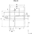
- the feeding element 51 and the strip conductor 41 are disposed on the same surface of the resin substrate 43. As illustrated in FIG. 14 , the boundary between the feeding element 51 and the strip conductor 41 is the feed point 44 and coincides with an edge 42a of the ground plane 42 in plan view from the Z-axis direction.
- FIG. 17 indicates measurement results obtained using aluminosilicate glass (Dragontrail (trademark) of Asahi Glass Co., Ltd.) for the cover substrate 61, and using a copper paste with a resistivity of 18 ⁇ /cm for the radiating element 52.
- the copper paste (composition for conductor) includes copper particles and a resin binder.
- the amount of thermosetting resin in the copper paste needs to be determined so that the set resin does not reduce the conductivity of the copper particles. When the amount of the set resin is too large, the set resin prevents the copper particles from contacting each other, and increases the volume resistivity of the conductor.
- the amount of thermosetting resin may be determined based on the ratio between the volume of the copper particles and the gaps between the copper particles. Generally, the amount of thermosetting resin is preferably 5 to 50 parts by mass and more preferably 5 to 20 parts by mass relative to 100 parts by mass of the copper particles. When the amount of thermosetting resin is greater than or equal to 5 parts by mass, the copper paste has a good rheological property. When the amount of thermosetting resin is less than or equal to 50 parts by mass, the volume resistivity of the conductor film can be maintained at a low level.
- FIGs. 18 and 19 are graphs indicating evaluation results of the positional robustness of the antenna device 3.
- the evaluation results (for five cases) of FIG. 18 were obtained by moving the cover substrate 61 in the upward (TOP) direction and the downward (BOTTOM) direction along the Y-axis in FIG. 14 relative to a design value (center) by a 2-mm pitch, without moving the resin substrate 43 in FIG. 13 .
- T2 indicates a case where the cover substrate 61 was moved by 2 mm in the upward (TOP) direction relative to the center
- T4 indicates a case where the cover substrate 61 was moved by 4 mm in the upward (TOP) direction relative to the center.
- L2 indicates a case where the cover substrate 61 was moved by 2 mm in the leftward (LEFT) direction relative to the center
- L4 indicates a case where the cover substrate 61 was moved by 4 mm in the leftward (LEFT) direction relative to the center
- R2 indicates a case where the cover substrate 61 was moved by 2 mm in the rightward (RIGHT) direction relative to the center
- R4 indicates a case where the cover substrate 61 was moved by 4 mm in the rightward (RIGHT) direction relative to the center.
- the feeding element 151 and the strip conductor 141 are disposed on the same surface of the substrate 143.
- the boundary between the feeding element 151 and the strip conductor 141 is the feed point 144 and coincides with an edge 142a of the ground plane 142 in plan view from the Z-axis direction.
- the feeding element 151 is a linear conductor that extends linearly in the Y-axis direction from an end 151a connected to the feed point 144 to an end 151b.
- the line width of the feeding element 151 was set at a constant value of 1.9 mm
- the line width of the radiating element 152 was set at a constant value of 1.9 mm.
- a dielectric substrate (BT resin (registered trademark), CCL-HL870 (M) (MITSUBISHI GAS CHEMICAL COMPANY, INC.)) with a relative permittivity of 3.4, tan ⁇ of 0.003, and a substrate thickness of 0.8 mm was assumed to be used.
- a dielectric substrate (LTCC)) with a relative permittivity of 9.0, tan ⁇ of 0.004, and a substrate thickness of 1.0 mm was assumed to be used.
- the resonance frequency f 21 of a feeding element can be shifted without changing the resonance frequencies f 11 and f 12 of a radiating element, by changing the length of the feeding element with the width of the radiating element fixed. For example, by decreasing the length of the feeding element, the resonance frequency f 21 of the feeding element can be shifted toward the high-frequency side between the resonance frequencies f 11 and f 12 of the radiating element, and can also be shifted to a frequency higher than the resonance frequency f 12 of the radiating element. On the other hand, by increasing the length of the feeding element, the resonance frequency f 21 of the feeding element can be shifted toward the low-frequency side, and can also be shifted to a frequency lower than the resonance frequency f 11 of the radiating element.
- FIG. 22 is a graph illustrating S11 characteristics at the resonance frequencies F 11 and f 12 obtained under the simulation conditions of FIG. 21 by decreasing the length L51 of the feeding element 51 by 5 mm from 45 mm to 15 mm with the length L52 of the radiating element 152 fixed at 95 mm.
- the horizontal axis indicates a frequency ratio p between the resonance frequency f 21 of the fundamental mode of the feeding element 151 and the resonance frequency f 12 of the second-order mode of the radiating element 152.
- the frequency ratio p is less than 1 (i.e., f 21 is lower than f 12 ) when the length L51 of the feeding element 151 is 45 mm, 40 mm, 35 mm, or 30 mm. Also in FIG. 22 , the frequency ratio p is greater than 1 (i.e., f 21 is higher than f 12 ) when the length L51 of the feeding element 151 is 25 mm, 20 mm, or 15 mm.
- FIG. 22 illustrates a case where the length L51 of the feeding element 151 and the length L52 of the radiating element 152 are adjusted, the resonance frequency f 11 is set at 0.97 GHz, and the resonance frequency f 12 is set at 1.97 GHz.
- a relationship between the frequency ratio p and S11 at the resonance frequencies f 11 and f 12 which is similar to that illustrated by FIG. 22 , can be obtained even when the lengths L51 and L52 are adjusted and the resonance frequencies f 11 and f 12 are set at other frequencies (f 11 : 1.79 GHz, f 12 : 3.65 GHz; f 11 : 2.51 GHz, f 12 : 5.20 GHz).
- the upper limit p 2 of the frequency ratio p within which S11 at the resonance frequency f 11 satisfies S11 ⁇ -4 [dB], also changes depending on the length of the gap L68.
- FIG. 23 is a graph illustrating a change in the upper limit p 2 of the frequency ratio p, within which S11 at the resonance frequency f 11 satisfies S11 ⁇ -4 [dB], when the gap L68 is increased by 0.5 mm from 1.0 mm to 5.0 mm. Simulation conditions used to obtain the results of FIG. 23 were substantially the same as those used to obtain the results of FIG. 21 .
- the shape of the feeding element 151 is changed to an L-shape as illustrated in FIG. 24 , excellent matching can be achieved both at the resonance frequency of the fundamental mode and the resonance frequency of the second-order mode of the radiating element as long as the frequency ratio p is greater than or equal to 0.7 and less than or equal to (0.1801 ⁇ x -0.468 ).
- the feeding element in an L-shape, it is possible to reduce the size of an antenna device.
- FIG. 24 is a perspective view of an antenna device 5 according to an embodiment of the present invention.
- FIG. 24 is obtained by calculating S11 based on a simulation model formed on a computer, and also measuring S11 using an antenna device actually produced. Descriptions of configurations of the antenna device 5 similar to those of the above embodiments may be omitted or simplified.
- the antenna device 5 includes an L-shaped feeding element 151 connected to a feed point 144, a radiating element 152 that is coupled with the feeding element 151 by electromagnetic field coupling, and a microstrip line 140 connected to the feed point 144.
- the feeding element 151 of the antenna device 5 is a linear conductor that bends at a right angle at a bent part 151c between an end 151a and an end 151b.
- the feeding element 151 includes a linear conductor portion extending in the Y-axis direction between the end 151a and the bent part 151c, and a liner conductor portion extending in the X-axis direction between the bent part 151c and the end 151b.
- the radiating element 152 includes a linear conductor portion that overlaps the linear conductor portion of the feeding element 151 between the bent part 151c and the end 151b in plan view seen from the Z-axis direction.
- the bent part 151c is located between the end 152a and the end 152b in plan view seen from the Z-axis direction.
- FIG. 25 is a graph illustrating the S11 characteristic of the antenna device 5 of FIG. 24 .
- "Sim.” Indicates S11 analyzed on a computer
- "Exp.” Indicates S11 measured using an actually-produced antenna device.
- the line width of the feeding element 151 was set at a constant value of 1.9 mm, and the line width of the radiating element 152 was set at a constant value of 1.9 mm.
- a dielectric substrate (BT resin (registered trademark), CCL-HL870 (M) (MITSUBISHI GAS CHEMICAL COMPANY, INC.)) with a relative permittivity of 3.4, tan ⁇ of 0.003, and a substrate thickness of 0.8 mm was assumed to be used.
- a dielectric substrate (LTCC)) with a relative permittivity of 9.0, tan ⁇ of 0.004, and a substrate thickness of 1.0 mm was assumed to be used.
- the entire length of the feeding element 151 substantially equals to (L70+L53).
- the feeding element 21 and the radiating element 22 exemplified by FIG. 1A are implemented as linear conductors extending linearly.
- the feeding element 21 and/or the radiating element 22 may be implemented as a linear conductor including a bent conductor portion.
- the feeding element 21 and/or the radiating element 22 may include an L-shaped conductor portion or a meander-shaped conductor portion.
- the feeding element 21 and/or the radiating element 22 may be implemented as a linear conductor that branches.
- a feeding element may include a stub or a matching circuit. This configuration makes it possible to reduce an area occupied by the feeding element on a substrate.
- FIG. 26 is a plan view of a computer simulation model for analyzing operations of an antenna device 6 including a meander-shaped radiating element. Descriptions of configurations of the antenna device 6 similar to those of the above embodiments may be omitted or simplified. FIG. 26 exemplifies a radiating element having a meander shape.
- the antenna device 6 includes a radiating element 252 that is coupled with an L-shaped feeding element 151 by electromagnetic field coupling.
- the radiating element 252 has a meander shape that is axisymmetric about a symmetric axis in the Y-axis direction, and includes a linear conductor portion that overlaps a linear conductor portion between a bent part 151c and an end 151b of the feeding element 151 in plan view seen from the Z-axis direction.
- the radiating element 252 is formed on one of the surfaces of the substrate 161 that is closer to the substrate 143 on which the feeding element 151 is formed.
- the entire length of the radiating element 252 is ⁇ /2.
- the radiating element 252 is represented by a solid line to improve visibility.
- the radiating element 252 may be implemented as a linear conductor having a point-symmetric meandering shape.
- FIG. 27 is a graph illustrating the S11 characteristic of the antenna device 6 of FIG. 26 .
- the shortest distance between the feeding element 151 and the radiating element 252 was 2 mm.
- the line width of the feeding element 151 was set at a constant value of 1.9 mm, and the line width of the radiating element 252 was set at a constant value of 1.9 mm.
- a dielectric substrate (BT resin (registered trademark) of MITSUBISHI GAS CHEMICAL COMPANY, INC.) with a relative permittivity of 3.4, tan ⁇ of 0.0015, and a substrate thickness of 0.8 mm was assumed to be used.
- the substrate 161 a glass plate with a relative permittivity of 7.0 and a substrate thickness of 1.0 mm was assumed to be used.
- the entire length of the feeding element 151 substantially equals to (L70+L53).
- a radiating element is not necessarily formed on a flat surface.
- a radiating element may be formed along a curved surface as illustrated by FIG. 28.
- FIG. 28 is a perspective view of a wireless communication apparatus 7 including a cover glass 331 with a curved surface on which a radiating element 352 is formed.
- the wireless communication apparatus 7 has a configuration similar to the configuration of the wireless communication apparatus 2 (see FIG. 6 ), and is a portable wireless apparatus.
- the wireless communication apparatus 7 includes a housing 330 and the cover glass 331 that entirely covers an image display surface of a display disposed in the housing 330.
- An antenna device according to an embodiment of the present invention is housed in the housing 330.
- the antenna device housed in the housing 330 includes a resin substrate 343 on which a microstrip line is formed.
- a ground plane 342 is formed on one surface of the resin substrate 343, and a linear strip conductor 341 is formed on the opposite surface of the resin substrate 343.
- An edge 342a is an edge of the ground plane 342.
- the antenna device housed in the housing 330 includes a feeding element 351 connected via a feed point 344 to the strip conductor 341, and a radiating element 352 that is coupled with the feeding element 351 by electromagnetic field coupling.
- the feeding element 351 and the strip conductor 341 are disposed on the same surface of the resin substrate 343.
- the feeding element 351 is a meander-shaped linear conductor connected to the feed point 344 that is connected to the strip conductor 341.
- the radiating element 352 is formed on a recessed surface of the cover glass 331 near the feeding element 351.
- FIG. 29 is a graph illustrating an S11 characteristic of the antenna device housed in the housing 330 of the wireless communication apparatus 7 of FIG. 28 .
- the cover glass 331 has a curved surface, and has a thickness of 1.1 mm.
- the cover glass 331 includes a portion with a radius of curvature of 200 mm in the X direction and a portion with a radius of curvature of 2000 mm in the Y direction.
- the cover glass 331 is attached to a frame of the housing 330.
- a feeding element may be formed on a surface of a substrate or inside of the substrate. Also, a chip component including a feeding element and a medium contacting the feeding element may be mounted on a substrate. This configuration makes it possible to easily mount a feeding element contacting a predetermined medium on a substrate.
- a medium contacting a radiating element or a feeding element is not limited to a dielectric material, and may be a magnetic material or a substrate including a mixture of a dielectric material and a magnetic material as a base material.
- dielectric materials include resin, glass, glass ceramic, Low-Temperature Co-Fired Ceramics (LTCC), and alumina.
- LTCC Low-Temperature Co-Fired Ceramics
- a mixture of a dielectric material and a magnetic material may be any material that includes a transition element such as Fe, Ni, or Co and a metal or an oxide including a rare-earth element such as Sm or Nd.
- mixtures of a dielectric material and a magnetic material include hexagonal ferrite, spinel ferrite (e.g., Mn-Zn ferrite and Ni-Zn ferrite), garnet ferrite, permalloy, and Sendust (registered trademark).
Abstract
Description
- The present invention relates to an antenna device and a wireless apparatus (e.g., a portable wireless apparatus such as a cellphone) including the antenna device.
- In recent years, the number of antennas provided in, for example, a portable wireless apparatus has increased and the integration density of a circuit board of such a portable wireless apparatus has increased. For this reason, antennas are disposed, for example, on or in a housing of a portable wireless apparatus away from a circuit board.
- For example,
Patent Document 1 discloses an antenna conductor (radiating conductor) that is formed on an outer surface of a housing, and is in physical contact with a feed pin provided on a circuit board (seeFIG. 2 of Patent Document 1). When such a feed pin is used, to improve the reliability of a connection in a case where an external impact is applied, a special connection terminal such as a spring-pin connector having a mechanism to reduce the impact is used. Also,Patent Document 2 discloses a feeding mechanism as an example where such a special mechanism is not used. -
Patent Document 2 discloses an antenna device where a radiating conductor is formed on a housing, and a capacitor plate is disposed at an end of an upright feeder line on a circuit board (seeFIG. 1 of Patent Document 2). The capacitor plate and the radiating - conductor are capacitively coupled, and power is fed to the radiating conductor in a non-contact manner. This non-contact feeding mechanism is resistant to an impact. In a case where a brittle material such as glass or ceramics is used for a housing on which antennas are formed and a feed pin is used for feeding, the housing may be damaged and the antennas may become inoperable when a strong external impact is applied to the housing and stress is concentrated on one point on the housing. A non-contact feeding mechanism is very effective to prevent such problems.
-
- [Patent Document 1] Japanese Laid-Open Patent Publication No.
2009-060268 - [Patent Document 2] Japanese Laid-Open Patent Publication No.
2001-244715 - However, with a feeding mechanism where a radiating conductor and a capacitor plate are capacitively coupled, its capacitance value greatly varies when the positional relationship between the radiating conductor and the capacitor plate, particularly a gap between them, becomes different from a designed value due to, for example, a production error. This in turn makes it difficult to achieve impedance matching. Also, the same problem may occur when the positional relationship between the radiating conductor and the capacitor plate changes due to vibration during use.
- One object of the present invention is to provide an antenna device including a non-contact feeding mechanism that is highly robust in terms of the positional relationship between a radiating conductor and a feeding element, and a wireless apparatus including the antenna device.
- To achieve the above object, the present invention provides an antenna device including a feeding element connected to a feed point, and a radiating element disposed at a distance from the feeding element. The feeding element is coupled with the radiating element by electromagnetic field coupling to feed the radiating element so that the radiating element functions as a radiating conductor.
- The present invention makes it possible to provide a non-contact feeding mechanism that is highly robust in terms of the positional relationship between a radiating conductor and a feeding element.
-
-
FIG. 1A is a perspective view of an analytic model of an antenna device according to an embodiment; -
FIG. 1B is a perspective view of an analytic model of an antenna device according to an embodiment; -
FIG. 2 is a graph illustrating an S11 characteristic of a feeding element according to an embodiment; -
FIG. 3 is a graph illustrating An S11 characteristic of an antenna device according to an embodiment; -
FIG. 4 is a graph illustrating a relationship between a shortest distance D1 between a feeding element and a radiating element and total efficiency of the radiating element; -
FIG. 5A is a drawing illustrating an antenna device where a crossing angle between a feeding element and a radiating element is +90°; -
FIG. 5B is a drawing illustrating an antenna device where a crossing angle between a feeding element and a radiating element is +45°; -
FIG. 5C is a drawing illustrating an antenna device where a crossing angle between a feeding element and a radiating element is 0°; -
FIG. 5D is a drawing illustrating an antenna device where a crossing angle between a feeding element and a radiating element is -45°; -
FIG. 5E is a drawing illustrating an antenna device where a crossing angle between a feeding element and a radiating element is -90°; -
FIG. 6 is a see-through plan view of a wireless apparatus where an antenna device is installed; -
FIG. 7 is a side view of a wireless apparatus where an antenna device is installed; -
FIG. 8A is a side view of a wireless apparatus where an antenna device is installed; -
FIG. 8B is a side view of a wireless apparatus where an antenna device is installed; -
FIG. 9A is a see-through plan view of a wireless apparatus where multiple radiating elements are fed by one feeding element; -
FIG. 9B is a see-through plan view of a wireless apparatus where multiple radiating elements are fed by one feeding element; -
FIG. 10A is a see-through plan view of a wireless apparatus where multiple antenna devices are installed; -
FIG. 10B is a see-through plan view of a wireless apparatus where multiple antenna devices are installed; -
FIG. 10C is a see-through plan view of a wireless apparatus where multiple antenna devices are installed; -
FIG. 11 is a see-through plan view of a wireless apparatus where antenna elements are disposed orthogonal to a radiating element of an antenna device; -
FIG. 12 is a side view illustrating the positional relationship in a height direction between a radiating element and other antenna elements; -
FIG. 13 is a perspective view of an antenna device that has been actually produced; -
FIG. 14 is a see-through plan view illustrating a configuration of the antenna device ofFIG. 13 ; -
FIG. 15 is a graph illustrating an S11 characteristic of a first example of an antenna device; -
FIG. 16 is a graph illustrating an S11 characteristic of a second example of an antenna device; -
FIG. 17 is a graph illustrating an S11 characteristic of a third example of an antenna device; -
FIG. 18 is a graph illustrating an S11 characteristic indicating positional robustness in a Y-axis direction; -
FIG. 19 is a graph illustrating an S11 characteristic indicating positional robustness in an X-axis direction; -
FIG. 20 is a perspective view of an analytic model of an antenna device according to an embodiment; -
FIG. 21 is a graph illustrating an S11 characteristic of the antenna device ofFIG. 20 ; -
FIG. 22 is a graph illustrating a relationship between a frequency ratio p between a resonance frequency f21 of a fundamental mode of a feeding element and a resonance frequency f12 of a second-order mode of a radiating element, and an S11 characteristic calculated for each of resonance frequencies f11 and f12 of the radiating element; -
FIG. 23 is a graph illustrating a relationship between an upper limit value p2 of a frequency ratio p and a value x obtained by normalizing a shortest distance between a feeding element and a radiating element; -
FIG. 24 is a perspective view of an antenna device according to an embodiment; -
FIG. 25 is a graph illustrating an S11 characteristic of the antenna device ofFIG. 24 ; -
FIG. 26 is a plan view of an analytic model of an antenna device according to an embodiment; -
FIG. 27 is a graph illustrating an S11 characteristic of the antenna device ofFIG. 26 ; -
FIG. 28 is a perspective view of a wireless apparatus according to an embodiment; and -
FIG. 29 is a graph illustrating an S11 characteristic of an antenna device installed in the wireless apparatus ofFIG. 28 . - Embodiments of the present invention are described below with reference to the accompanying drawings.
-
FIG. 1A is a perspective view of a computer simulation model for analyzing operations of anantenna device 1 according to an embodiment of the present invention. Microwave Studio (registered trademark) (CST Computer Simulation Technology AG) is used as an electromagnetic field simulator. - The
antenna device 1 includes afeed point 14, aground plane 12, a radiatingelement 22, a feedingpart 36 for feeding the radiatingelement 22, and afeeding element 21 that is a conductor and disposed at a predetermined distance from the radiatingelement 22 in a Z-axis direction. The feedingpart 36 is a feeding part solely for the radiatingelement 22, and is not for theantenna device 1. A feeding part for theantenna device 1 is thefeed point 14. - In the example of
FIG. 1A , the radiatingelement 22 and thefeeding element 21 overlap each other in plan view seen from the Z-axis direction. However, the radiatingelement 22 and thefeeding element 21 do not necessarily overlap each other in plan view seen from the Z-axis direction, as long as the feedingelement 21 and the radiatingelement 22 are at such a distance from each other that they can be coupled by electromagnetic field coupling. For example, the feedingelement 21 and the radiatingelement 22 may overlap each other in plan view seen from any direction such as an X-axis direction or a Y-axis direction. - The radiating
element 22 is a line-shaped antenna conductor that extends along anedge 12a of theground plane 12. For example, the radiatingelement 22 is a linear conductor including a conductor part 23 that is at a predetermined shortest distance from theedge 12a in the Y-axis direction and extends parallel to theedge 12a in the X-axis direction. With the radiatingelement 22 including the conductor part 23 extending along theedge 12a, it is possible, for example, to easily control the directivity of theantenna device 1. In the example ofFIG. 1A , the radiatingelement 22 has a line shape. However, the radiatingelement 22 may have any other shape such as an L-shape. - The feeding
element 21 is connected to thefeed point 14 that uses theground plane 12 as a ground reference, and is a linear conductor that can feed the radiatingelement 22 by electromagnetic field coupling via the feedingpart 36. In the example ofFIG. 1A , the feedingelement 21 is a linear conductor that extends linearly in the Y-axis direction from anend 21a connected to thefeed point 14 to anend 21b. Theend 21b is an open end to which no conductor is connected. - The
feed point 14 is a feeding part connected, for example, to a transmission line using theground plane 12 or a feeding line. Examples of transmission lines include a microstrip line, a strip line, and a coplanar waveguide with a ground plane (i.e., a coplanar waveguide including a ground plane disposed on a surface opposite to a conductor surface). Examples of feeding lines include a feeder line and a coaxial cable. - The feeding
element 21 is connected via thefeed point 14 to, for example, a feeding circuit (e.g., an integrated circuit such as an IC chip) mounted on a circuit board. The feedingelement 21 may also be connected to the feeding circuit via different types of transmission lines and/or feeding lines as described above. The feedingelement 21 feeds the radiatingelement 22 by electromagnetic field coupling. -
FIG. 1A exemplifies theground plane 12 having a rectangular shape and extends in an XY plane.FIG. 1A also exemplifies the feedingelement 21 that is a linear conductor extending in a direction perpendicular to theedge 12a of theground plane 12 and parallel to the Y-axis, and the radiatingpart 22 that is a linear conductor extending in a direction perpendicular to the direction in which thefeeding element 21 extends and parallel to the X-axis. - The feeding
element 21 and the radiatingelement 22 are at such a distance from each other that they can be coupled by electromagnetic field coupling. The radiatingelement 22 is fed by the feedingelement 21 in a non-contact manner through electromagnetic field coupling at the feedingpart 36. By being fed as described above, the radiatingelement 22 functions as a radiating conductor of an antenna. As illustrated byFIG. 1A , when the radiatingelement 22 is a linear conductor connecting two points, a resonance current (distribution) similar to that of a half-wave dipole antenna is formed on the radiatingelement 22. In other words, the radiatingelement 22 functions as a dipole antenna that resonates at a half-wavelength of a predetermined frequency (which is hereafter referred to as a dipole mode). Also, a radiating element may be a loop conductor as in anantenna device 8 ofFIG. 1B. FIG. 1B exemplifies aloop radiating element 24. When a radiating element is a loop conductor, a resonance current (distribution) similar to that of a loop antenna is formed on the radiating element. In other words, the radiatingelement 24 functions as a loop antenna that resonates at one wavelength of a predetermined frequency (which is hereafter referred to as a "loop mode"). - Electromagnetic field coupling uses a resonance phenomenon of an electromagnetic field, and is disclosed, for example, in a non-patent document (A. Kurs et al, "Wireless Power Transfer via Strongly Coupled Magnetic Resonances," Science Express, Vol. 317, No. 5834, pp. 83-86, Jul. 2007). Electromagnetic field coupling is also called "electromagnetic field resonant coupling" or "electromagnetic field resonance coupling". Electromagnetic field coupling is a technology where resonators that resonate at the same frequency are disposed close to each other, one of the resonators is caused to resonate to generate a near field (non-radiation field area) between the resonators, and energy is transmitted to another one of the resonators via coupling by the near field. Also, electromagnetic field coupling indicates coupling via an electric field and a magnetic field at a high frequency excluding electrostatic capacitive coupling and electromagnetic induction coupling. Here, "excluding electrostatic capacitive coupling and electromagnetic induction coupling" does not indicate completely eliminating electrostatic capacitive coupling and electromagnetic induction coupling, but indicates that their influence is negligible. A medium between the feeding
element 21 and the radiatingelement 22 may be air or a dielectric material such as glass or resin. It is preferable to not place a conductive material such as a ground plane or a display between the feedingelement 21 and the radiatingelement 22. - A configuration that is resistant to an impact is obtained by coupling the
feeding element 21 and the radiatingelement 22 by electromagnetic field coupling. That is, using electromagnetic field coupling makes it possible to feed the radiatingelement 22 using thefeeding element 21 without bringing thefeeding element 21 and the radiatingelement 22 into physical contact with each other, and thereby makes it possible to provide a configuration that is more resistant to an impact than a contact feeding mechanism requiring a physical contact. - Also, compared with a configuration where the radiating
element 22 is fed by electrostatic capacitive coupling, the configuration where the radiatingelement 22 is fed by electromagnetic field coupling makes it possible to reduce the decrease in the total efficiency (antenna gain) of the radiatingelement 22 at an operating frequency in relation to a change in the distance (coupling distance) between the feedingelement 21 and the radiatingelement 22. Here, total efficiency is a quantity calculated by a formula "antenna radiation efficiency x return loss", and is defined as the efficiency of an antenna relative to input power. Therefore, coupling thefeeding element 21 and the radiatingelement 22 by electromagnetic field coupling makes it possible to more flexibly determine the positions of thefeeding element 21 and the radiatingelement 22, and also makes it possible to improve positional robustness. Here, high positional robustness indicates that displacement of thefeeding element 21 and the radiatingelement 22 has little influence on the total efficiency of the radiatingelement 22. Also, being able to flexibly determine the positions of thefeeding element 21 and the radiatingelement 22 makes it possible to easily reduce the space necessary to install theantenna device 1. Also, using electromagnetic field coupling makes it possible to feed the radiatingelement 22 by the feedingelement 21 without using an extra component such as a capacitor plate. Accordingly, compared with a case where electrostatic capacitive coupling is used for feeding, using electromagnetic field coupling makes it possible to feed the feedingelement 21 with a simple configuration. - In
FIG. 1A , the feedingpart 36 at which thefeeding element 21 feeds the radiatingelement 22 is located at a portion of the radiatingelement 22 that is between anend 22a and anend 22b of the radiatingelement 22 and other than a center portion 90 (i.e., a portion between thecenter portion 90 and theend 22a or between thecenter portion 90 and theend 22b). Thus, the feedingpart 36 is located at a portion of the radiatingelement 22 other than a lowest impedance portion (in this example, the center portion 90) whose impedance is lowest in the radiatingelement 22 at a resonance frequency of a fundamental mode of the radiatingelement 22. This makes it possible to easily achieve impedance matching of theantenna device 1. The feedingpart 36 is defined by a conductor portion of the radiatingelement 22 that is closest to thefeeding element 21 and closest to thefeed point 14. - In the dipole mode, the impedance of the radiating
element 22 gradually increases from thecenter portion 90 toward theend 22a and theend 22b. When the feedingelement 21 and the radiatingelement 22 are coupled by electromagnetic field coupling at high impedance greater than a predetermined value, a slight change in the impedance between the feedingelement 21 and the radiatingelement 22 does not greatly affect impedance matching. Therefore, to easily achieve impedance matching, the feedingpart 36 of the radiatingelement 22 is preferably located at a high impedance portion of the radiatingelement 22. - For example, to easily achieve the impedance matching of the
antenna device 1, the feedingpart 36 is preferably located at a portion of the radiatingelement 22 that is away from a lowest impedance portion (in this example, the center portion 90), whose impedance is lowest in the radiatingelement 22 at a resonance frequency of the fundamental mode of the radiatingelement 22, by a distance greater than or equal to 1/8 (more preferably 1/6, and further preferably 1/4) of the entire length of the radiatingelement 22. InFIG. 1A , the entire length of the radiatingelement 22 is indicated by L22, and the feedingpart 36 located at a position closer to theend 22a than thecenter portion 90. - On the other hand, when the distance between a capacitor plate and a radiating conductor increases even slightly in a case where impedance matching is achieved in low impedance coupling such as electrostatic capacitive coupling as disclosed in
Patent Document 2, the capacitance decreases and the impedance between the capacitor plate and the radiating conductor increases. As a result, the impedance matching becomes unachievable. - When Le21 indicates an electrical length that imparts a fundamental mode of resonance to the
feeding element 21, Le22 indicates an electrical length that imparts a fundamental mode of resonance to the radiatingelement 22, and λ indicates a wavelength on thefeeding element 21 or the radiatingelement 22 at a resonance frequency f11 of the fundamental mode of the radiatingelement 22, Le21 is preferably less than or equal to (3/8)·λ, and Le22 is preferably greater than or equal to (3/8)·λ and less than or equal to (5/8)·λ when the fundamental mode of resonance of the radiatingelement 22 is the dipole mode or greater than or equal to (7/8)· λ and less than or equal to (9/8)·λ when the fundamental mode of resonance of the radiatingelement 22 is the loop mode. - Le21 is preferably less than or equal to (3/8) ·λ. When it is desired to flexibly design the shape of the
feeding element 21 including the presence or absence of theground plane 12, Le21 is more preferably greater than or equal to (1/8)·λ and less than or equal to (3/8)·λ, and further preferably greater than or equal to (3/16)·λ and less than or equal to (5/16)·λ When Le21 is within the above ranges, the feedingelement 21 resonates properly at a design frequency (resonance frequency f11) of the radiatingelement 22, the feedingelement 21 and the radiatingelement 22 resonate with each other without depending on theground plane 12 of theantenna device 1, and appropriate electromagnetic field coupling can be achieved. - When the
ground plane 12 is formed such that theedge 12a extends along the radiatingelement 22, a resonance current (distribution) can be formed on thefeeding element 21 and theground plane 12 as a result of an interaction between the feedingelement 21 and theedge 12a, and thefeeding element 21 resonates and is coupled with the radiatingelement 22 by electromagnetic field coupling. For this reason, there is no specific lower limit for the electrical length Le21 of thefeeding element 21 as long as the feedingelement 21 has a length that is sufficient to be physically coupled with the radiatingelement 22 by electromagnetic field coupling. When electromagnetic field coupling is achieved, it indicates that impedance matching is achieved. In this case, it is not necessary to determine the electrical length of thefeeding element 21 according to the resonance frequency of the radiatingelement 22. This in turn makes it possible to freely design thefeeding element 21 as a radiating conductor, and thereby makes it possible to easily implement theantenna device 1 supporting multiple frequencies. The sum of the length of theedge 12a of theground plane 12 extending along the radiatingelement 22 and the electrical length of thefeeding element 21 is preferably greater than or equal to (1/4)·λ of the design frequency (resonance frequency f11). - When the feeding
element 21 does not include a component such as a matching circuit, a physical length L21 of thefeeding element 21 is determined by λg1=λ0·k1, where λ0 indicates the wavelength of a radio wave in a vacuum at the resonance frequency of the fundamental mode of the radiatingelement 22 and k1 indicates a shortening coefficient of a wavelength shortening effect in an actual environment. Here, k1 is calculated based on, for example, a relative permittivity, a relative permeability (e.g., an effective relative permittivity (εr1) and an effective relative permeability (µr1) of an environment of the feeding element 21), and a thickness of a medium (environment) such as a dielectric substrate where the feedingelement 21 is placed, and a resonance frequency. That is, L21 is less than or equal to (3/8)· λg1. The shortening coefficient may be calculated based on the physical properties described above, or by actual measurement. For example, a resonance frequency of a target element placed in an environment whose shortening coefficient is to be obtained is measured, a resonance frequency of the same target element is measured in an environment whose shortening coefficient for each frequency is known, and the shortening coefficient may be calculated based on a difference between the measured resonance frequencies. - The physical length L21 of the
feeding element 21 is a physical length that gives Le21. In an ideal case where no other factor is considered, the physical length L21 is equal to Le21. When, for example, the feedingelement 21 includes a matching circuit, L21 is preferably greater than zero and less than or equal to Le21. By using a matching circuit such as an inductor, L21 can be reduced (i.e., the size of thefeeding element 21 can be reduced). - When the fundamental mode of resonance of the radiating
element 22 is the dipole mode (i.e., when the radiatingelement 21 is a linear conductor having open ends), Le22 is preferably greater than or equal to (3/8) ·λ and less than or equal to (5/8)·λ, more preferably greater than or equal to (7/16)·λ and less than or equal to (9/16)·λ, and further preferably greater than or equal to (15/32)·λ and less than or equal to (17/32)· λ. When a higher-order mode is taken into account, Le22 is preferably greater than or equal to (3/8)·λ·m and less than or equal to (5/8)·λ·m, more preferably greater than or equal to (7/16)·λ·m and less than or equal to (9/16)·λ·m, and further preferably greater than or equal to (15/32)·λ·m and less than or equal to (17/32)·λ·m. Here, m indicates a mode number of a higher-order mode and is represented by a natural number. The value of m is preferably an integer between 1 through 5, and more preferably an integer between 1 through 3. In this case, m=1 indicates the fundamental mode. When Le22 is within the above ranges, the radiatingelement 22 functions sufficiently as a radiating conductor, and the efficiency of theantenna device 1 becomes high. - When the fundamental mode of resonance of the radiating
element 22 is the loop mode (i.e., when the radiatingelement 21 is a loop conductor), Le22 is preferably greater than or equal to (7/8)·λ and less than or equal to (9/8)·λ, more preferably greater than or equal to (15/16)·λ and less than or equal to (17/16)· ·λ, and further preferably greater than or equal to (31/32)·λ and less than or equal to (33/32)·λ. For a higher-order mode, Le22 is preferably greater than or equal to (7/8)·λ·m and less than or equal to (9/8)·λ·m, more preferably greater than or equal to (15/16)·λ·m and less than or equal to (17/16)·λ·m, and further preferably greater than or equal to (31/32)·λ·m and less than or equal to (33/32)·λ·m. - A physical length L22 of the radiating
element 22 is determined by λg2=λ0·k2, where λ0 indicates the wavelength of a radio wave in a vacuum at the resonance frequency of the fundamental mode of the radiatingelement 22 and k2 indicates a shortening coefficient of a wavelength shortening effect in an actual environment. Here, k2 is calculated based on, for example, a relative permittivity, a relative permeability (e.g., an effective relative permittivity (εr2) and an effective relative permeability (µr2) of an environment of the radiating element 22), and a thickness of a medium (environment) such as a dielectric substrate where the radiatingelement 22 is placed, and a resonance frequency. Thus, L22 is greater than or equal to (3/8)· λg2 and less than or equal to (5/8)·λg2 when the fundamental mode of resonance of the radiatingelement 22 is the dipole mode, and is greater than or equal to (7/8)·λg2 and less than or equal to (9/8)·λg2 when the fundamental mode of resonance of the radiatingelement 22 is the loop mode. The physical length L22 of the radiatingelement 22 is a physical length that gives Le22. In an ideal case where no other factor is considered, the physical length L22 is equal to Le22. Even when L22 is reduced by using, for example, a matching circuit such as an inductor, L22 is preferably greater than zero and less than or equal to Le22, and more preferably greater than or equal to 0.4xLe22 and less than or equal to lxLe22. In the case of theloop radiating element 24 ofFIG. 1B , L22 corresponds to the inner circumference of the radiatingelement 24. - For example, when BT resin (registered trademark), CCL-HL870 (M) (MITSUBISHI GAS CHEMICAL COMPANY, INC.) with a relative permittivity of 3.4, tanδ of 0.003, and a substrate thickness of 0.8 mm is used as a dielectric substrate, L21 is 20 mm when the design frequency of the
feeding element 21 used as a radiating conductor is 3.5 GHz, and L22 is 34 mm when the design frequency of the radiatingelement 22 is 2.2 GHz. - Also, when the interaction between the feeding
element 21 and theedge 12a of theground plane 12 can be used as illustrated byFIG. 1A andFIG. 1B , the feedingelement 21 may be used as a radiating element as described above. The radiatingelement 22 is a radiating conductor that is fed by the feedingelement 21 in a non-contact manner through electromagnetic field coupling at the feedingpart 36, and functions as a λ/2 dipole antenna in the example ofFIG. 1A . The feedingelement 21 is a linear feeding conductor that can feed the radiatingelement 22, and is also a radiating conductor that can function as a monopole antenna (e.g., λ/4 monopole antenna) when being fed at thefeed point 14. This function of thefeeding element 21 is described with reference toFIGs. 2 and 3. FIG. 2 is a graph illustrating an S11 characteristic of thefeeding element 21 obtained by a simulation. The S11 characteristic is a type of characteristic of high-frequency electronic components, and is represented by a return loss for each frequency.FIG. 2 illustrates the S11 characteristic obtained in a simulation performed using a configuration where the radiatingelement 22 is removed from the configuration of theantenna device 1 ofFIG. 1A . In the simulation, the feedingelement 21 is fed by gap feeding at thefeed point 14 between theend 21a of thefeeding element 21 and theedge 12a of theground plane 12. When the design frequency is set at 3.75 GHz and L21 of thefeeding element 21 is set at 20 mm (=λ0/4), the feedingelement 21 can function as a λ/4 monopole antenna (i.e., a radiating element) using theground plane 12 as indicated byFIG. 2 . -
FIG. 3 illustrates the S11 characteristic obtained in a simulation performed using a configuration where the radiatingelement 22 that is parallel to theedge 12a of theground plane 12 is added to thefeeding element 21 that functions as a λ/4 monopole antenna as described with reference toFIG. 2 . In the simulation, the feedingelement 21 is fed by gap feeding at thefeed point 14. The radiatingelement 22 is disposed away from the feedingelement 21 in the Z-axis direction by a distance that enables electromagnetic field coupling such that when seen from the Z-axis direction, theend 22a of the radiatingelement 22 overlaps a portion of thefeeding element 21 between theend 21a and theend 21b. When the design frequency is set at 3 GHz and L22 of the radiatingelement 22 is set at 50 mm (=λ0/2), the radiatingelement 22 can resonate in a frequency band between 2 and 2.5 GHz as indicated byFIG. 3 . This indicates that the radiatingelement 22 can be configured to function as an antenna even when the feedingelement 21 is configured to function as a radiating element. Also, when the resonance frequency of the radiatingelement 22 is f1 and the resonance frequency of thefeeding element 21 is f2, it is possible to use the radiation function of the radiatingelement 22 at the resonance frequency f2. - When the radiation function of the
feeding element 21 is used and thefeeding element 21 does not include a component such as a matching circuit, the physical length L21 of thefeeding element 21 is determined by λg3=λ1·k1, where λ1 indicates the wavelength of a radio wave in a vacuum at the resonance frequency f2 of thefeeding element 21 and k1 indicates a shortening coefficient of a wavelength shortening effect in an actual environment. Here, k1 is calculated based on, for example, a relative permittivity, a relative permeability (e.g., an effective relative permittivity (εr1) and an effective relative permeability (µr1) of an environment of the feeding element 21), and a thickness of a medium (environment) such as a dielectric substrate where the feedingelement 21 is placed, and a resonance frequency. That is, L21 is greater than or equal to (1/8)·λg3 and less than or equal to (3/8)·λg3, and is preferably greater than or equal to (3/16)·λg3 and less than or equal to (5/16)·λg3. The physical length L21 of thefeeding element 21 is a physical length that gives Le21. In an ideal case where no other factor is considered, the physical length L21 is equal to Le21. When, for example, the feedingelement 21 includes a matching circuit, L21 is preferably greater than zero and less than or equal to Le21. By using a matching circuit such as an inductor, L21 can be reduced (i.e., the size of thefeeding element 21 can be reduced). - In the simulations performed to obtain the results of
FIGs. 2 and 3 , theground plane 12 ofFIG. 1A is assumed to be a virtual conductor having a horizontal length L1 of 100 mm, a vertical length L2 of 150 mm, and no thickness. Also, the gap between theedge 12a of theground plane 12 and theend 21a of thefeeding element 21 is set at 1 mm. Further, it is assumed that no dielectric substrate exists. - When λ0 indicates the wavelength of a radio wave in a vacuum at the resonance frequency of the fundamental mode of the radiating
element 22, a shortest distance x (>0) between the feedingelement 21 and the radiatingelement 22 is preferably less than or equal to 0.2xλ0 (more preferably less than or equal to 0.1xλ0, and further preferably less than or equal to 0.05xλ0). Arranging the feedingelement 21 and the radiatingelement 22 at the shortest distance x described above makes it possible to improve the total efficiency of the radiatingelement 22. - Here, the shortest distance x indicates a linear distance between the closest parts of the
feeding element 21 and the radiatingelement 22. -
FIG. 4 is a graph illustrating a relationship between the shortest distance x and the total efficiency of the radiatingelement 22. Here, the total efficiency indicates a radiation efficiency obtained taking into account the return loss of an antenna, and is calculated by a formula η×(1-|Γ|2) where η indicates a radiation efficiency and Γ indicates a return loss. In a simulation performed to obtain the results ofFIG. 4 , theground plane 12 ofFIG. 1A is assumed to be a virtual conductor having a horizontal length L1 of 100 mm, a vertical length L2 of 150 mm, and no thickness. Also, the gap between theedge 12a of theground plane 12 and theend 21a of thefeeding element 21 is set at 1 mm. Also in the simulation, it is assumed that gap feeding is performed at thefeed point 14, and amatching circuit 15 having an inductance of 20 nH is inserted in series between thefeed point 14 and theend 21a of thefeeding element 21. Further, L21 of thefeeding element 21 is set at 5 mm, and L22 of the radiatingelement 22 is set at 50 mm. Thus, properly adjusting the matchingcircuit 15 connected to thefeeding element 21 makes it possible to achieve electromagnetic field coupling even when L21 of thefeeding element 21 is reduced, and thereby makes it possible to reduce the mounting area of thefeeding element 21 and to reduce an area occupied by a circuit board. - Although the
matching circuit 15, which is an inductor, is used in this example, a capacitor may be used instead of an inductor. Also, although an inductor is inserted in series in this example, the circuit configuration is not limited to this example, and any known matching technology may be used. Further, even when the length of thefeeding element 21 is constant, it is possible to adaptively change operating frequencies and frequency bands by electronically changing the constant of the matchingcircuit 15. This in turn makes it possible to implement a tunable antenna. - The radiating
element 22 is disposed away from the feedingelement 21 in the Z-axis direction such that when seen from the Z-axis direction, theend 22a of the radiatingelement 22 overlaps a portion of thefeeding element 21 between theend 21a and theend 21b. In this case, the shortest distance x corresponds to the linear distance between theend 22a of the radiatingelement 22 facing the feedingelement 21 and theend 21b of thefeeding element 21 facing the radiatingelement 22. - The results of
FIG. 4 are obtained by calculating the total efficiency of the radiatingelement 22 while changing the shortest distance x by moving the radiatingelement 22 horizontally away from the feedingelement 21 in the Z-axis direction with the position of thefeeding element 21 fixed. The vertical axis ofFIG. 4 indicates the total efficiency of the radiatingelement 22 when the frequency of a radio wave is set at 2.6 GHz. The horizontal axis ofFIG. 4 indicates the shortest distance x that is normalized to one wavelength (i.e., the distance per one wavelength). - As illustrated by
FIG. 4 , the total efficiency of the radiatingelement 22 decreases as the distance between the radiatingelement 22 and thefeeding element 21 increases because the coupling strength of electromagnetic field coupling between the radiatingelement 22 and thefeeding element 21 decreases. Accordingly, the shortest distance x is preferably less than or equal to 0.2xλ0 (more preferably less than or equal to 0.1xλ0, and further preferably less than or equal to 0.05xλ0) in order to improve the total efficiency of the radiatingelement 22. - Also, a distance for which the
feeding element 21 and the radiatingelement 22 run parallel to each other at the shortest distance x is preferably less than or equal to 3/8, more preferably less than or equal to 1/4, and further preferably less than or equal to 1/8 of the physical length of the radiatingelement 22. Because the coupling strength between portions of thefeeding element 21 and the radiatingelement 22 at the shortest distance x is high, when the distance for which thefeeding element 21 and the radiatingelement 22 run parallel to each other at the shortest distance x is long, the feedingelement 21 is coupled strongly with both of a high-impedance portion and a low-impedance portion of the radiatingelement 22. As a result, the impedance matching may become unachievable. Therefore, the distance for which thefeeding element 21 and the radiatingelement 22 run parallel to each other at the shortest distance x is preferably short so that the feedingelement 21 is strongly coupled with only a portion of the radiatingelement 22 having relatively constant impedance, and the impedance matching is achieved. -
FIGs. 5A through 5E illustrate five variations of theantenna device 1 where the feedingelement 21 and the radiatingelement 22 intersect at different crossing angles. InFIGs. 5A through 5E , a 10-mm end portion of the radiatingelement 22 from theend 22a is rotated about theend 21b of thefeeding element 21. As long as the feedingelement 21 and the radiatingelement 22 are coupled by electromagnetic field coupling, desired total efficiency of the radiatingelement 22 can be achieved regardless of the crossing angle at which thefeeding element 21 and the radiatingelement 22 intersect. Also, the characteristic of the total efficiency of the radiatingelement 22 is little affected by a change in the crossing angle. -
FIG. 6 is a plan view of awireless communication apparatus 2 where theantenna device 1 is installed. InFIG. 6 , thewireless communication apparatus 2 is made transparent so that the layout of the components of theantenna device 1 including thefeeding element 21, the radiatingelement 22, and theground plane 12 can be seen. Theground plane 12 inFIG. 6 is a ground plane of a circuit board (not shown). Thisground plane 12 is electrically connected to a ground plane of a system (not shown), and therefore theground plane 12 of theantenna device 1 indicates the ground plane of the system. - The
wireless communication apparatus 2 is a portable wireless apparatus. Examples of thewireless communication apparatus 2 include electronic apparatuses such as an information terminal, a cellphone, a smartphone, a personal computer, a game machine, a television, and music and video players. - The
wireless communication apparatus 2 includes ahousing 30, adisplay 32 disposed in thehousing 30, and acover glass 31 that entirely covers an image display surface of thedisplay 32. Here, thehousing 30 is a component that forms a part or the whole of the outer shape of thewireless communication apparatus 2, and is a container that houses and protects, for example, a circuit board including theground plane 12. Thehousing 30 may be composed of multiple components including aback cover 33. - The
display 32 may include a touch sensor function. Thecover glass 31 is a dielectric substrate that is transparent or translucent to allow a user to see an image displayed on thedisplay 32, and is a tabular component stacked on thedisplay 32. Thecover glass 31 has a size that is the same as or slightly smaller than the size of the outer shape of thehousing 30. - An outer surface of the
cover glass 31 that is opposite to a surface of thecover glass 31 facing thedisplay 32 is defined as a first surface, and the surface facing thedisplay 32 is defined as a second surface. - When the radiating
element 22 is formed on the second surface of thecover glass 31, the feedingelement 21 exemplified inFIG. 6 includes a conductor portion that is parallel to theedge 12a of theground plane 12, and is disposed inside of the outer edge of thedisplay 32 when thedisplay 32 is seen from the Z-axis direction. However, the feedingelement 21 may instead be disposed outside of the outer edge of thedisplay 32 when thedisplay 32 is seen from the Z-axis direction, or may be disposed to extend across the outer edge of thedisplay 32 from the inside to the outside. - The radiating
element 22 exemplified inFIG. 6 includes a conductor portion that is parallel to anedge 12b of theground plane 12, and is disposed outside of the outer edge of thedisplay 32 when thedisplay 32 is seen from the Z-axis direction. This configuration makes it possible to place the radiatingelement 22 away from the circuit board (not shown) where theground plane 12 is formed or from thedisplay 32, and is therefore preferable in order to prevent noise interference. However, the radiatingelement 22 may instead be disposed inside of the outer edge of thedisplay 32 when thedisplay 32 is seen from the Z-axis direction, or may include a conductor portion that extends across the outer edge of thedisplay 32 from the inside to the outside. - When a metal is used for a part of the
housing 30 forming a part or the whole of the outer shape of thewireless communication apparatus 2, the radiatingelement 22 may be implemented by the metal constituting the part of thehousing 30. In, for example, recent smartphones, only a small space is available for installing an antenna. Therefore, using a metal constituting a part of a housing as a radiating element makes it possible effectively use a space. - As a wireless apparatus according to a preferred embodiment of the present invention, as illustrated by
FIG. 6 , thewireless communication apparatus 2 may include thehousing 30, thedisplay 32 disposed in thehousing 30, and thecover glass 31 that entirely covers the image display surface of thedisplay 32. Also, the feedingelement 21 of theantenna device 1 of an embodiment of the present invention may be disposed in thehousing 30, and the radiatingelement 22 of theantenna device 1 may be disposed on a surface of the cover glass 31 (preferably the second surface of the cover glass 31). -
FIGs. 7 ,8A, and 8B exemplify positional relationships among components of theantenna device 1 and thewireless communication apparatus 2 in a height direction that is parallel to the Z axis. -
FIG. 7 is a side view of thewireless communication apparatus 2 where the radiatingelement 22 of theantenna device 1 is disposed on thecover glass 31. In the example ofFIG. 7 , the radiatingelement 22 is formed flatly on the periphery of the second surface of thecover glass 31 facing thedisplay 32. However, the radiatingelement 22 may be formed on the first surface of thecover glass 31 that is opposite to the second surface facing thedisplay 32, or on an edge face of thecover glass 31. As illustrated byFIGs. 6 and 7 , the radiatingelement 22 is preferably disposed such that a portion of the radiatingelement 22 extends along an edge of theground plane 12. This configuration makes it possible, for example, to control the antenna directivity. - When the radiating
element 22 is formed on a surface of thecover glass 31, the radiatingelement 22 may be formed by applying a conductive paste of, for example, copper or silver onto the surface of thecover glass 31 and firing the applied conductive paste. As the conductive paste, a low-temperature-firing conductive paste that can be fired at a temperature that does not reduce the strength of a chemically-strengthened glass forming thecover glass 31 may be used. Also, to prevent the degradation of a conductor due to oxidation, the conductive paste may be, for example, plated. Also, the radiatingelement 22 may be formed by attaching a copper or silver foil via an adhesive layer to a surface of thecover glass 31. A decorative print may be formed on a part of thecover glass 31, and a conductor may be formed on the part of thecover glass 31. When a black masking film is formed on the periphery of thecover glass 31 to hide, for example, wiring, the radiatingelement 22 may be formed on the black masking film. -
FIGs. 8A and 8B illustrate examples where the radiatingelement 22 of theantenna device 1 is formed on theback cover 33 of thewireless communication apparatus 2. An inner surface of theback cover 33 that faces thedisplay 32 is defined as a first surface, and a surface opposite to the first surface is defined as a second surface. In the examples ofFIGs. 8A and 8B , the radiatingelement 22 is formed flatly on the periphery of the first surface of theback cover 33 of thewireless communication apparatus 2 to face thedisplay 32. However, the radiatingelement 22 may be formed on the second surface of theback cover 33 that is opposite to the first surface facing thedisplay 32, on an edge face of theback cover 33, or inside of theback cover 33. Theback cover 33 may be a part of thehousing 30 illustrated inFIG. 6 , or may be provided as a separate component. Also, theback cover 33 may be made of a dielectric material such as resin or a metal material. When theback cover 33 is made of a conductive material, the radiatingelement 22 is preferably insulated from theback cover 33. The radiatingelement 22 is not necessarily disposed in the periphery of theback cover 33, and may be disposed in any other appropriate position. - Although a resin such as ABS resin is generally used as a material of the
housing 30 and theback cover 33, other materials such as transparent glass, colored glass, and opalescent glass may also be used for thehousing 30 and theback cover 33. - Colored glass may be produced by adding, for example, Co, Mn, Fe, Ni, Cu, Cr, V, Zn, Bi, Er, Tm, Nd, Sm, Sn, Ce, Pr, Eu, Ag, or Au as a colorant to components of glass. Examples of opalescent glass include crystallized glass and phase-separated glass that use scattering of light. As crystalized glass, lithium disilicate (Li2Si2O5) crystal, nepheline ((NaK)AlSiO4) crystal, and sodium fluoride (NaF) are particularly preferable.
- Also, a glass-ceramic substrate obtained by sintering a mixture of glass powder, ceramic powder, and pigment powder may be used as a material for the
housing 30 and theback cover 33. - Glass powder having any composition may be used as long as it can be sintered together with ceramic powder at an appropriate temperature. When silver wiring is formed by sintering at a temperature between 800 °C and 900 °C , glass composition with a softening point between 700 °C and 900 °C is preferable. Also, to improve the strength as a housing, glass composition including SiO2 such as SiO2-B2O3-Al2O3-RO-R2O is preferable. Here, RO indicates alkaline earth metal oxide, and R2O indicates alkali metal oxide. Al2O3 is not essential.
- Characteristics such as color and strength of glass ceramic can be flexibly adjusted by changing a combination of glass powder and ceramic powder.
- Glass powder may be colored by adding, as a colorant, an element such as Co, Mn, Fe, Ni, Cu, Cr, V, Zn, Bi, Er, Tm, Nd, Sm, Sn, Ce, Pr, Eu, Ag, or Au that causes absorption when added to glass component. Also, the color of glass ceramic may be more flexibly adjusted by mixing pigment powder with glass powder and ceramic powder and sintering the mixture. A typical example of an inorganic pigment is a composite oxide pigment composed of elements selected from, for example, Fe, Cr, Co, Cu, Mn, Ni, Ti, Sb, Zr, Al, Si, and P. To improve the strength, glass powder with glass composition and a particle size that are suitable to be co-sintered with ceramic powder may be selected. As ceramic powder, for example, Al2O3 or ZrO2 with a high strength may be used. The shape of ceramic powder also greatly influences the strength. The permittivity may be adjusted by selecting ceramic powder with a desired permittivity. The thermal expansion coefficient may be adjusted by selecting a combination of glass powder (glass composition) and ceramic powder having desired thermal expansion coefficients. Also, sintering shrinkage of glass ceramic may also be adjusted by selecting the shape of ceramic powder. A conductor pattern may be formed by screenprinting a pattern with a commercial silver paste for sintering at a temperature between 800 °C and 900 °C, and drying the printed pattern. Alternatively, a conductor pattern may be formed by pasting a copper or silver foil.
- When the glass ceramic substrate is used for the
back cover 33, theback cover 33 may be formed as a multilayer structure. In this case, a conductor pattern may be formed on an inner layer of the multilayer structure, and a part of the conductor pattern may be used as a radiating element. For example, as illustrated byFIG. 8B , the radiatingelement 22 may be formed on an inner layer of theback cover 33 formed with a two-layer glass ceramic substrate. With this configuration, the radiatingelement 22 is not exposed to the outside. Therefore, this configuration makes it possible to prevent degradation and peeling of a conductor resistor, and to improve reliability. The multilayer structure of theback cover 33 may include more than two layers, and the radiatingelement 22 may be formed on the outermost layer of the multilayer structure, and on any inner layer of the multilayer structure. - When the radiating
element 22 is formed on thecover glass 31, the radiatingelement 22 is preferably formed as a linear conductor. On the other hand, when the radiatingelement 22 is formed on thehousing 30 or theback cover 33, the radiatingelement 22 may be disposed in any position and may be formed as any one of a linear conductor, a loop conductor, and a patch conductor. The patch conductor may have any planar shape such as a substantially-square shape, a substantially-rectangular shape, a substantially-circular shape, or a substantially-oval shape. - Also, as exemplified by
FIGs. 7 ,8A, and 8B , the feedingelement 21, the radiatingelement 22, and theground plane 12 may be disposed in different positions in a height direction that is parallel to the Z axis. Also, some of or all of the positions of thefeeding element 21, the radiatingelement 22, and theground plane 12 in the height direction may be the same. - As a wireless apparatus according to a preferred embodiment of the present invention, as illustrated by
FIGs. 8A and 8B , thewireless communication apparatus 2 may include the housing 30 (including the back cover 33) and thedisplay 32 disposed in thehousing 30. Also, the feedingelement 21 of theantenna device 1 of an embodiment of the present invention may be disposed in thehousing 30, and the radiatingelement 22 of theantenna device 1 may be disposed on a surface of theback cover 33 or inside of theback cover 33. -
FIGs. 9A and9B are see-through plan views of thewireless communication apparatus 2 including theantenna device 1 where multiple radiation elements are fed by onefeeding element 21. In the examples ofFIGs. 9A and9B , two radiation elements are fed by onefeeding element 21. However, three or more radiation elements may be fed by onefeeding element 21. Using multiple radiating elements makes it possible to provide a multiband or wideband antenna device, and to control the directivity of an antenna device. - In the example of
FIG. 9A , two radiating elements 22-1 and 22-2 are disposed along two adjacent edges of thedisplay 32 that are orthogonal to each other, and the radiating elements 22-1 and 22-2 are fed by onefeeding element 21. The radiating element 22-1 includes a portion that extends along the left edge of thedisplay 32, and the radiating element 22-2 includes a portion that extends along the upper edge of thedisplay 32. - In the example of
FIG. 9B , both of two radiating elements 22-1 and 22-2 are disposed along an edge of thedisplay 32, and the radiating elements 22-1 and 22-2 are fed by onefeeding element 21. Each of the radiating elements 22-1 and 22-2 includes a portion that extends along the right edge of thedisplay 32. -
FIGs. 10A ,10B , and10C are see-through plan views of thewireless communication apparatus 2 includingmultiple antenna devices 1. In the examples ofFIGs. 10A ,10B , and10C , two radiating elements 22-A1 and 22-A2 are fed by a feeding element 21-1, and two radiating elements 22-B1 and 22-B2 are fed by a feeding element 21-2. - Also in the examples of
FIGs. 10A ,10B , and10C , one of radiating elements of each antenna device is disposed orthogonal to another one of the radiating elements. Here, "another one of the radiating elements" may indicate "all other radiating elements", "another radiating element", and "other radiating elements". Arranging the radiatingelements 22 orthogonal to each other makes it possible to suppress the interference between the radiatingelements 22. - In the example of
FIG. 10A , the radiating element 22-A1 and the radiating element 22-B1 include conductor portions that are orthogonal to each other, and the radiating element 22-A2 and the radiating element 22-B2 include conductor portions that are orthogonal to each other. In the example ofFIG. 10B , the radiating element 22-A1 includes a conductor portion that is orthogonal to the radiating elements 22-B2 and 22-B1. In the example ofFIG. 10C , the radiating element 22-A1 and the radiating element 22-B1 include conductor portions that are orthogonal to each other, and the radiating element 22-A2 and the radiating element 22-B2 include conductor portions that are orthogonal to each other. - When a wireless apparatus of the present invention includes multiple antennas, the antennas may include both of an antenna employing a non-contact feeding mechanism based on electromagnetic field coupling and an antenna employing another feeding mechanism. Examples of other feeding mechanisms include a contact mechanism using a cable, a flexible substrate, a pin with a spring, and any other elastic part.
-
FIG. 11 is a see-through plan view of thewireless communication apparatus 2 whereother antenna elements element 22 that is fed by the feedingelement 21. The radiatingelement 22 includes a conductor portion that is orthogonal to theantenna elements element 22. Arranging the radiatingelement 22 orthogonal to theantenna elements element 22 and theantenna elements -
FIG. 12 is a side view illustrating the positional relationship in the height direction between the radiation element and theantenna elements FIG. 12 , the radiatingelement 22 is formed on a surface of thecover glass 31 facing thedisplay 32, and theantenna elements feeding element 21 are formed on a surface of theback cover 33 facing thedisplay 32. This configuration makes it possible to drastically increase an area available for installing antennas and improve the flexibility in the layout of antennas. Accordingly, this configuration makes it possible to suppress the interference between antennas, and is suitable for a MIMO (Multi Input Multi Output) antenna configuration. -
FIG. 13 is a perspective view of anantenna device 3 that has been actually produced.FIG. 14 is a see-through plan view illustrating a configuration of theantenna device 3. - The
antenna device 3 includes afeeding element 51 connected to afeed point 44, a radiatingelement 52 that is disposed at a distance from the feedingelement 51 and coupled with the feedingelement 51 by electromagnetic field coupling, and amicrostrip line 40 connected to thefeed point 44. The feedingelement 51 is connected at thefeed point 44 to astrip conductor 41 of themicrostrip line 40, and therefore themicrostrip line 40 practically functions as a feeding line. The radiatingelement 52 is formed on one of the surfaces of acover substrate 61 that is closer to aresin substrate 43 on which thefeeding element 51 is formed. - The
microstrip line 40 includes theresin substrate 43. Aground plane 42 is formed on one surface of theresin substrate 43, and thelinear strip conductor 41 is formed on the opposite surface of theresin substrate 43. Thefeed point 44 is a connection point between thestrip conductor 41 and thefeeding element 51. It is assumed that an integrated circuit such as an IC chip connected via themicrostrip line 40 to thefeed point 44 is mounted on theresin substrate 43. - The feeding
element 51 and thestrip conductor 41 are disposed on the same surface of theresin substrate 43. As illustrated inFIG. 14 , the boundary between the feedingelement 51 and thestrip conductor 41 is thefeed point 44 and coincides with anedge 42a of theground plane 42 in plan view from the Z-axis direction. - Also, as illustrated by
FIG. 13 , theantenna device 3 includes thecover substrate 61 that is disposed above theresin substrate 43 and fixed viacolumns 71 to theresin substrate 43. The radiatingelement 52 is formed on one of the surfaces of thecover substrate 61 that is closer to theresin substrate 43 on which thefeeding element 51 is formed. The feedingelement 51 and the radiatingelement 52 are separated from each other by a space formed by thecolumns 71. InFIG. 14 , the radiatingelement 52 is represented by a solid line to improve visibility. -
FIGs. 15, 16 , and17 are graphs illustrating the S11 characteristic of the radiatingelement 52 measured by changing materials of thecover substrate 61 ofFIGs. 13 and14 . In the measurement, BT resin (registered trademark), CCL-HL870 (M) (MITSUBISHI GAS CHEMICAL COMPANY, INC.) with a relative permittivity of 3.4, tanδ of 0.003, and a substrate thickness of 0.8 mm was used for theresin substrate 43. -
FIG. 15 indicates measurement results obtained using RT/duroid 6010 (registered trademark) (Rogers Corporation) with a relative permittivity of 10.2, tanδ of 0.0023, and a substrate thickness of 0.635 mm for thecover substrate 61, and using a copper foil with a thickness of 18 µm for the radiatingelement 52. Dimensions of the structure inFIG. 14 were set as follows: L11=120 mm, L12=49.15 mm, L3=60 mm, L4=10.95 mm, L5=1.9 mm, W1=86 mm, W2=74.15 mm, W3=28 mm, W4=10.95 mm, W5=1.9 mm, and W6=29 mm. -
FIG. 16 indicates measurement results obtained using BT resin (registered trademark), CCL-HL870 (M) (MITSUBISHI GAS CHEMICAL. COMPANY, INC.) with a relative permittivity of 3.4, tanδ of 0.003, and a substrate thickness of 0.8 mm for thecover substrate 61, and using a copper foil with a thickness of 18 µm for the radiatingelement 52. Dimensions of the structure inFIG. 14 were set as follows: L11=120 mm, L12=49.15 mm, L3=60 mm, L4=10.95 mm, L5=1.9 mm, W1=86 mm, W2=74.15 mm, W3=34 mm, W4=10.95 mm, W5=1.9 mm, and W6=26 mm. -
FIG. 17 indicates measurement results obtained using aluminosilicate glass (Dragontrail (trademark) of Asahi Glass Co., Ltd.) for thecover substrate 61, and using a copper paste with a resistivity of 18 µΩ/cm for the radiatingelement 52. The copper paste (composition for conductor) includes copper particles and a resin binder. - Commercial copper particles may be used as the copper particles. Using surface-modified copper particles (Japanese Laid-Open Patent Publication No.
2011-017067 - The amount of thermosetting resin in the copper paste needs to be determined so that the set resin does not reduce the conductivity of the copper particles. When the amount of the set resin is too large, the set resin prevents the copper particles from contacting each other, and increases the volume resistivity of the conductor. The amount of thermosetting resin may be determined based on the ratio between the volume of the copper particles and the gaps between the copper particles. Generally, the amount of thermosetting resin is preferably 5 to 50 parts by mass and more preferably 5 to 20 parts by mass relative to 100 parts by mass of the copper particles. When the amount of thermosetting resin is greater than or equal to 5 parts by mass, the copper paste has a good rheological property. When the amount of thermosetting resin is less than or equal to 50 parts by mass, the volume resistivity of the conductor film can be maintained at a low level.
- In the measurement of
FIG. 17 , dimensions of the structure inFIG. 14 were set as follows: L11=120 mm, L12=49.15 mm, L3=60 mm, L4=10.95 mm, L5=1.9 mm, W1=86 mm, W2=74.15 mm, W3=28 mm, W4=10.95 mm, W5=1.9 mm, and W6=29 mm. - As the results of
FIGs. 15, 16 , and17 indicate, regardless of the material of thecover substrate 61, the S11 characteristic of the radiatingelement 52 was sufficient for the radiatingelement 52 to function as an antenna. -
FIGs. 18 and19 are graphs indicating evaluation results of the positional robustness of theantenna device 3. The evaluation results (for five cases) ofFIG. 18 were obtained by moving thecover substrate 61 in the upward (TOP) direction and the downward (BOTTOM) direction along the Y-axis inFIG. 14 relative to a design value (center) by a 2-mm pitch, without moving theresin substrate 43 inFIG. 13 . InFIG. 18 , T2 indicates a case where thecover substrate 61 was moved by 2 mm in the upward (TOP) direction relative to the center, and T4 indicates a case where thecover substrate 61 was moved by 4 mm in the upward (TOP) direction relative to the center. Also, B2 indicates a case where thecover substrate 61 was moved by 2 mm in the downward (BOTTOM) direction relative to the center, and B4 indicates a case where thecover substrate 61 was moved by 4 mm in the downward (BOTTOM) direction relative to the center. The evaluation results (for five cases) ofFIG. 19 were obtained by moving thecover substrate 61 in the leftward (LEFT) direction and the rightward (RIGHT) direction along the X-axis inFIG. 14 relative to a design value (center) by a 2-mm pitch, without moving theresin substrate 43 inFIG. 13 . InFIG. 19 , L2 indicates a case where thecover substrate 61 was moved by 2 mm in the leftward (LEFT) direction relative to the center, and L4 indicates a case where thecover substrate 61 was moved by 4 mm in the leftward (LEFT) direction relative to the center. Also inFIG. 19 , R2 indicates a case where thecover substrate 61 was moved by 2 mm in the rightward (RIGHT) direction relative to the center, and R4 indicates a case where thecover substrate 61 was moved by 4 mm in the rightward (RIGHT) direction relative to the center. - Moving the
cover substrate 61 results in a change in the positional relationship between the feedingelement 51 and the radiatingelement 52, and it is possible to evaluate how the S11 characteristic of the radiatingelement 52 changes depending on the change in the positional relationship. As the results ofFIGs. 18 and19 indicate, there is no significant change in the S11 characteristic of the radiatingelement 52 even when the positional relationship between the feedingelement 51 and the radiatingelement 52 changes. This indicates that theantenna device 3 has high positional robustness. - An antenna device of an embodiment of the present invention can function as a multiband antenna that uses a second-order mode where a radiating element resonates at a resonance frequency that is about two times greater than the resonance frequency of a fundamental mode (first-order mode). Next, conditions in which excellent matching can be achieved in the fundamental mode and the second-order mode of a radiating element of an antenna device of an embodiment when the radiating element operates in the dipole mode are described with reference to an analytic model of
FIG. 20 . -
FIG. 20 is a perspective view of a computer simulation model for analyzing operations of anantenna device 4 according to an embodiment of the present invention. Descriptions of configurations of theantenna device 4 similar to those of the above embodiments may be omitted or simplified. Theantenna device 4 includes afeeding element 151 connected to afeed point 144, a radiatingelement 152 that is coupled with thefeeding element 151 by electromagnetic field coupling, and amicrostrip line 140 connected to thefeed point 144. Thefeeding element 151 is connected at thefeed point 144 to astrip conductor 141 of themicrostrip line 140, and therefore themicrostrip line 140 practically functions as a feeding line. - The
microstrip line 140 includes asubstrate 143. Aground plane 142 is formed on one surface of thesubstrate 143, and thelinear strip conductor 141 is formed on the opposite surface of thesubstrate 143. Thefeed point 144 is a connection point between thestrip conductor 141 and thefeeding element 151. It is assumed that an integrated circuit such as an IC chip connected via themicrostrip line 140 to thefeed point 144 is mounted on thesubstrate 143. - The
feeding element 151 and thestrip conductor 141 are disposed on the same surface of thesubstrate 143. The boundary between the feedingelement 151 and thestrip conductor 141 is thefeed point 144 and coincides with anedge 142a of theground plane 142 in plan view from the Z-axis direction. Thefeeding element 151 is a linear conductor that extends linearly in the Y-axis direction from anend 151a connected to thefeed point 144 to anend 151b. - Also, the
antenna device 4 includes acover substrate 161 that is disposed at a distance from thesubstrate 143 in the direction of a normal line of thesubstrate 143 that is parallel to the Z-axis direction. The radiatingelement 152 is formed on one of the surfaces of thecover substrate 161 that is closer to thesubstrate 143 on which thefeeding element 151 is formed. The radiatingelement 152 is a linear conductor that linearly connects anend 152a and anend 152b. - The radiating
element 152 is disposed away from thefeeding element 151 in the Z-axis direction such that when seen in the Z-axis direction, theend 152a of the radiatingelement 152 overlaps a portion of thefeeding element 151 between theend 151a and theend 151b. The shortest distance between the feedingelement 151 and theradiating element 151 coupled by electromagnetic field coupling corresponds to a gap L68 between thesubstrate 143 and thecover substrate 161. -
FIG. 21 is a graph illustrating the S11 characteristic of theantenna device 4 ofFIG. 20 . Simulation conditions used to obtain the results ofFIG. 21 were as follows: L61=130 mm, L62=110 mm, L63=10 mm, L64=200 mm, L65=180 mm, L66=10 mm, L67=30 mm, L68=2 mm, L69=67.5 mm, and L70=4.05 mm. - Also, the line width of the
feeding element 151 was set at a constant value of 1.9 mm, and the line width of the radiatingelement 152 was set at a constant value of 1.9 mm. As thesubstrate 143, a dielectric substrate (BT resin (registered trademark), CCL-HL870 (M) (MITSUBISHI GAS CHEMICAL COMPANY, INC.)) with a relative permittivity of 3.4, tanδ of 0.003, and a substrate thickness of 0.8 mm was assumed to be used. As thecover substrate 161, a dielectric substrate (LTCC)) with a relative permittivity of 9.0, tanδ of 0.004, and a substrate thickness of 1.0 mm was assumed to be used. - In
FIG. 21 , f11 indicates a resonance frequency of the fundamental mode of the radiatingelement 152, f12 indicates a resonance frequency of the second-order mode of the radiatingelement 152, and f21 indicates a resonance frequency of the fundamental mode of thefeeding element 151. Under the simulation conditions used to obtain the results ofFIG. 21 , by adjusting a length L51 of thefeeding element 151 to 50 mm and a length L52 of the radiatingelement 152 to 95 mm, the resonance frequency f11 of the fundamental mode of the radiatingelement 152 can be set at 0.97 GHz and the resonance frequency f12 of the second-order mode of the radiatingelement 152 can be set at 1.97 GHz. - With an antenna device of an embodiment of the present invention, the resonance frequency f21 of a feeding element can be shifted without changing the resonance frequencies f11 and f12 of a radiating element, by changing the length of the feeding element with the width of the radiating element fixed. For example, by decreasing the length of the feeding element, the resonance frequency f21 of the feeding element can be shifted toward the high-frequency side between the resonance frequencies f11 and f12 of the radiating element, and can also be shifted to a frequency higher than the resonance frequency f12 of the radiating element. On the other hand, by increasing the length of the feeding element, the resonance frequency f21 of the feeding element can be shifted toward the low-frequency side, and can also be shifted to a frequency lower than the resonance frequency f11 of the radiating element.
-
FIG. 22 is a graph illustrating S11 characteristics at the resonance frequencies F11 and f12 obtained under the simulation conditions ofFIG. 21 by decreasing the length L51 of thefeeding element 51 by 5 mm from 45 mm to 15 mm with the length L52 of the radiatingelement 152 fixed at 95 mm. InFIG. 22 , the horizontal axis indicates a frequency ratio p between the resonance frequency f21 of the fundamental mode of thefeeding element 151 and the resonance frequency f12 of the second-order mode of the radiatingelement 152. The frequency ration p is defined by a formula below.
- When the frequency ratio p is 1, f12 and f21 are the same frequency. When the frequency ratio p is less than 1, f21. is lower than f12. When the frequency ratio p is greater than 1, f21 is higher than f12. As the length L51 of the
feeding element 151 decreases, the resonance frequency f21 of thefeeding element 151 shifts toward the high-frequency side, and the frequency ratio p increases. - In
FIG. 22 , the frequency ratio p is less than 1 (i.e., f21 is lower than f12) when the length L51 of thefeeding element 151 is 45 mm, 40 mm, 35 mm, or 30 mm. Also inFIG. 22 , the frequency ratio p is greater than 1 (i.e., f21 is higher than f12) when the length L51 of thefeeding element 151 is 25 mm, 20 mm, or 15 mm. - When the S11 characteristic at a resonance frequency of a radiating element satisfies S11 < -4 [dB], it is easier to achieve excellent matching of the radiating element. According to the results of
FIG. 22 , excellent matching can be achieved both in the fundamental mode and the second-order mode of the radiatingelement 151 when the frequency ratio p is greater than or equal to 0.7 and less than or equal to 1.65. InFIG. 22 , a lower limit p1 of the frequency ratio p is 0.7, and an upper limit p2 of the frequency ratio p is 1.65. -
FIG. 22 illustrates a case where the length L51 of thefeeding element 151 and the length L52 of the radiatingelement 152 are adjusted, the resonance frequency f11 is set at 0.97 GHz, and the resonance frequency f12 is set at 1.97 GHz. Although details are omitted, a relationship between the frequency ratio p and S11 at the resonance frequencies f11 and f12, which is similar to that illustrated byFIG. 22 , can be obtained even when the lengths L51 and L52 are adjusted and the resonance frequencies f11 and f12 are set at other frequencies (f11: 1.79 GHz, f12: 3.65 GHz; f11: 2.51 GHz, f12: 5.20 GHz). That is, even when the resonance frequencies f11 and f12 are set at other frequencies, S11 at the resonance frequencies of the fundamental mode and the second-order mode of the radiating element satisfies S11 < -4 [dB] when the frequency ratio p is substantially in the range of greater than or equal to 0.7 and less than or equal to 1.65. - Because the coupling strength of electromagnetic field coupling changes depending on the length of the gap L68 (see
FIG. 20 ), the upper limit p2 of the frequency ratio p, within which S11 at the resonance frequency f11 satisfies S11 < -4 [dB], also changes depending on the length of the gap L68. -
FIG. 23 is a graph illustrating a change in the upper limit p2 of the frequency ratio p, within which S11 at the resonance frequency f11 satisfies S11 < -4 [dB], when the gap L68 is increased by 0.5 mm from 1.0 mm to 5.0 mm. Simulation conditions used to obtain the results ofFIG. 23 were substantially the same as those used to obtain the results ofFIG. 21 . InFIG. 23 , the horizontal axis indicates a value x(=L68/(c/f11)) (where c indicates the speed of light constant) obtained by normalizing the gap L68 by the wavelength λ0 in a vacuum at the resonance frequency f11. - According to
FIG. 23 , the following relational expression is obtained by approximating, according to a least-squares method, a relationship between the upper limit p2 of the frequency ratio p and the value x obtained by normalizing the gap L68 by the wavelength λ0.
- Thus, assuming that a resonance frequency of the fundamental mode of the feeding element is f21, a resonance frequency of the second-order mode of the radiating element is f12, a wavelength in a vacuum at the resonance frequency of the fundamental mode of the radiating element is λ0, and a value obtained by normalizing the shortest distance between the feeding element and the radiating element by λ0 is x, excellent matching is achieved at the resonance frequency of the fundamental mode and the resonance frequency of the second-order mode of the radiating element when the frequency ration p(=f21/f12) is greater than or equal to 0.7 and less than or equal to (0.1801·x-0.468).
- For example, even when the shape of the
feeding element 151 is changed to an L-shape as illustrated inFIG. 24 , excellent matching can be achieved both at the resonance frequency of the fundamental mode and the resonance frequency of the second-order mode of the radiating element as long as the frequency ratio p is greater than or equal to 0.7 and less than or equal to (0.1801·x-0.468). By forming the feeding element in an L-shape, it is possible to reduce the size of an antenna device. -
FIG. 24 is a perspective view of anantenna device 5 according to an embodiment of the present invention.FIG. 24 is obtained by calculating S11 based on a simulation model formed on a computer, and also measuring S11 using an antenna device actually produced. Descriptions of configurations of theantenna device 5 similar to those of the above embodiments may be omitted or simplified. Theantenna device 5 includes an L-shapedfeeding element 151 connected to afeed point 144, a radiatingelement 152 that is coupled with thefeeding element 151 by electromagnetic field coupling, and amicrostrip line 140 connected to thefeed point 144. - The
feeding element 151 of theantenna device 5 is a linear conductor that bends at a right angle at abent part 151c between anend 151a and anend 151b. Thefeeding element 151 includes a linear conductor portion extending in the Y-axis direction between theend 151a and thebent part 151c, and a liner conductor portion extending in the X-axis direction between thebent part 151c and theend 151b. The radiatingelement 152 includes a linear conductor portion that overlaps the linear conductor portion of thefeeding element 151 between thebent part 151c and theend 151b in plan view seen from the Z-axis direction. Thebent part 151c is located between theend 152a and theend 152b in plan view seen from the Z-axis direction. -
FIG. 25 is a graph illustrating the S11 characteristic of theantenna device 5 ofFIG. 24 . InFIG. 25 , "Sim." Indicates S11 analyzed on a computer, and "Exp." Indicates S11 measured using an actually-produced antenna device. Conditions used for the analysis and the measurement of the results ofFIG. 25 were as follows: L52=95 mm, L53=10.95 mm, L54=12 mm, L61=60 mm, L62=40 mm, L63=10 mm, L64=140 mm, L65=120 mm, L66=10 mm, L67=30 mm, L68=1 mm, L69=34.5 mm, and L70=14.05 mm. - Also, the line width of the
feeding element 151 was set at a constant value of 1.9 mm, and the line width of the radiatingelement 152 was set at a constant value of 1.9 mm. As thesubstrate 143, a dielectric substrate (BT resin (registered trademark), CCL-HL870 (M) (MITSUBISHI GAS CHEMICAL COMPANY, INC.)) with a relative permittivity of 3.4, tanδ of 0.003, and a substrate thickness of 0.8 mm was assumed to be used. As thecover substrate 161, a dielectric substrate (LTCC)) with a relative permittivity of 9.0, tanδ of 0.004, and a substrate thickness of 1.0 mm was assumed to be used. The entire length of thefeeding element 151 substantially equals to (L70+L53). - As illustrated by
FIG. 25 , similarly to the simulation results, excellent matching was achieved even using the actually-produced antenna device not only at the resonance frequency f11 of the fundamental mode and the resonance frequency f12 of the second-order mode of the radiating element, but also at the resonance frequency f21 of the fundamental mode of the feeding element. - An antenna device and a wireless apparatus including the antenna device according to the embodiments of the present invention are described above. However, the present invention is not limited to the described embodiments. Combinations of some or all of the embodiments and the variation and replacement of the embodiments may be made without departing from the scope of the present invention.
- For example, the feeding
element 21 and the radiatingelement 22 exemplified byFIG. 1A are implemented as linear conductors extending linearly. However, the feedingelement 21 and/or the radiatingelement 22 may be implemented as a linear conductor including a bent conductor portion. For example, the feedingelement 21 and/or the radiatingelement 22 may include an L-shaped conductor portion or a meander-shaped conductor portion. Also, the feedingelement 21 and/or the radiatingelement 22 may be implemented as a linear conductor that branches. Also, a feeding element may include a stub or a matching circuit. This configuration makes it possible to reduce an area occupied by the feeding element on a substrate. -
FIG. 26 is a plan view of a computer simulation model for analyzing operations of anantenna device 6 including a meander-shaped radiating element. Descriptions of configurations of theantenna device 6 similar to those of the above embodiments may be omitted or simplified.FIG. 26 exemplifies a radiating element having a meander shape. Theantenna device 6 includes aradiating element 252 that is coupled with an L-shapedfeeding element 151 by electromagnetic field coupling. - The radiating
element 252 has a meander shape that is axisymmetric about a symmetric axis in the Y-axis direction, and includes a linear conductor portion that overlaps a linear conductor portion between abent part 151c and anend 151b of thefeeding element 151 in plan view seen from the Z-axis direction. The radiatingelement 252 is formed on one of the surfaces of thesubstrate 161 that is closer to thesubstrate 143 on which thefeeding element 151 is formed. The entire length of the radiatingelement 252 is λ/2. InFIG. 26 , the radiatingelement 252 is represented by a solid line to improve visibility. Alternatively, the radiatingelement 252 may be implemented as a linear conductor having a point-symmetric meandering shape. -
FIG. 27 is a graph illustrating the S11 characteristic of theantenna device 6 ofFIG. 26 . Simulation conditions used to obtain the results ofFIG. 27 were as follows: L53=22.95 mm, L61=60 mm, L62=40 mm, L63=10 mm, L64=140mm, L65=120 mm, L66=10 mm, L67=30 mm, L69=34.5 mm, L70=9.5 mm, L81= 9.75 mm, L82=2.75 mm, L83=7.5 mm, L84=1.5 mm, L85=20.5 mm, L86=2.5 mm, L87=8 mm, and L88=18.5 mm. Also, the shortest distance between the feedingelement 151 and the radiating element 252 (i.e., a gap between thesubstrate 143 and the substrate 161) was 2 mm. Also, the line width of thefeeding element 151 was set at a constant value of 1.9 mm, and the line width of the radiatingelement 252 was set at a constant value of 1.9 mm. As thesubstrate 143, a dielectric substrate (BT resin (registered trademark) of MITSUBISHI GAS CHEMICAL COMPANY, INC.) with a relative permittivity of 3.4, tanδ of 0.0015, and a substrate thickness of 0.8 mm was assumed to be used. As thesubstrate 161, a glass plate with a relative permittivity of 7.0 and a substrate thickness of 1.0 mm was assumed to be used. The entire length of thefeeding element 151 substantially equals to (L70+L53). - As illustrated by
FIG. 27 , excellent matching was achieved at the resonance frequency of the fundamental mode and the resonance frequency of the second-order mode of the radiating element. - A radiating element is not necessarily formed on a flat surface. For example, a radiating element may be formed along a curved surface as illustrated by
FIG. 28. FIG. 28 is a perspective view of awireless communication apparatus 7 including acover glass 331 with a curved surface on which aradiating element 352 is formed. - The
wireless communication apparatus 7 has a configuration similar to the configuration of the wireless communication apparatus 2 (seeFIG. 6 ), and is a portable wireless apparatus. Thewireless communication apparatus 7 includes ahousing 330 and thecover glass 331 that entirely covers an image display surface of a display disposed in thehousing 330. An antenna device according to an embodiment of the present invention is housed in thehousing 330. - The antenna device housed in the
housing 330 includes aresin substrate 343 on which a microstrip line is formed. Aground plane 342 is formed on one surface of theresin substrate 343, and alinear strip conductor 341 is formed on the opposite surface of theresin substrate 343. Anedge 342a is an edge of theground plane 342. - The antenna device housed in the
housing 330 includes afeeding element 351 connected via afeed point 344 to thestrip conductor 341, and aradiating element 352 that is coupled with thefeeding element 351 by electromagnetic field coupling. Thefeeding element 351 and thestrip conductor 341 are disposed on the same surface of theresin substrate 343. Thefeeding element 351 is a meander-shaped linear conductor connected to thefeed point 344 that is connected to thestrip conductor 341. The radiatingelement 352 is formed on a recessed surface of thecover glass 331 near thefeeding element 351. -
FIG. 29 is a graph illustrating an S11 characteristic of the antenna device housed in thehousing 330 of thewireless communication apparatus 7 ofFIG. 28 . Conditions used to measure the results ofFIG. 29 were as follows: L91=12.5 mm, L92=105 mm, L93=5 mm, L94=11 mm, and L95=5.95 mm. - Also, the line width of the
feeding element 351 was set at a constant value of 0.5 mm, the line width of the radiatingelement 352 was set at a constant value of 2 mm, and the line width of thestrip conductor 341 was set at a constant value of 1.9 mm. Thecover glass 331 has a curved surface, and has a thickness of 1.1 mm. Thecover glass 331 includes a portion with a radius of curvature of 200 mm in the X direction and a portion with a radius of curvature of 2000 mm in the Y direction. Thecover glass 331 is attached to a frame of thehousing 330. - As illustrated by
FIG. 29 , excellent matching was achieved at the resonance frequency of the fundamental mode and the resonance frequency of the second-order mode of the radiating element. - A feeding element may be formed on a surface of a substrate or inside of the substrate. Also, a chip component including a feeding element and a medium contacting the feeding element may be mounted on a substrate. This configuration makes it possible to easily mount a feeding element contacting a predetermined medium on a substrate.
- A medium contacting a radiating element or a feeding element is not limited to a dielectric material, and may be a magnetic material or a substrate including a mixture of a dielectric material and a magnetic material as a base material. Examples of dielectric materials include resin, glass, glass ceramic, Low-Temperature Co-Fired Ceramics (LTCC), and alumina. A mixture of a dielectric material and a magnetic material may be any material that includes a transition element such as Fe, Ni, or Co and a metal or an oxide including a rare-earth element such as Sm or Nd. Examples of mixtures of a dielectric material and a magnetic material include hexagonal ferrite, spinel ferrite (e.g., Mn-Zn ferrite and Ni-Zn ferrite), garnet ferrite, permalloy, and Sendust (registered trademark).
- The present international application is based on and claims the benefit of priority of Japanese Patent Application No.
2012-161983 filed on July 20, 2012 -
- 1, 3, 4, 5, 6, 8 Antenna device
- 2, 7 Wireless communication apparatus
- 12 Ground plane
- 12a, 12b Edge
- 14 Feed point
- 15 Matching circuit
- 21 Feeding element
- 22, 24 Radiating element
- 23 Conductor portion
- 33, 330 Housing
- 31, 331 Cover glass
- 32 Display (an example of an image display unit)
- 33 Back cover
- 34, 35 Other antenna elements
- 36 Feeding part
- 40, 140 Microstrip line
- 41, 141, 341 Strip conductor
- 42, 142, 342 Ground plane
- 42a, 142a, 342a Edge
- 43, 343 Resin substrate
- 44, 144, 344 Feed point
- 51, 151, 351 Feeding element
- 52, 152, 252, 352 Radiating element
- 61, 161 Cover substrate
- 71 Column
- 90 Center portion
- 143 Substrate
- Further examples:
- 1. An antenna device, comprising:
- a feeding element connected to a feed point; and
- a radiating element disposed at a distance from the feeding element,
- wherein the feeding element is coupled with the radiating element by electromagnetic field coupling to feed the radiating element so that the radiating element functions as a radiating conductor.
- 2. The antenna device as described in example 1,
wherein when Le21 indicates an electrical length that imparts a fundamental mode of resonance to the feeding element, Le22 indicates an electrical length that imparts a fundamental mode of resonance to the radiating element, and A indicates a wavelength on the feeding element or the radiating element at a resonance frequency of the fundamental mode of the radiating element,
Le21 is less than or equal to (3/8)·λ, and
Le22 is greater than or equal to (3/8)·λ and less than or equal to (5/8)·λ when the fundamental mode of resonance of the radiating element is a dipole mode, or greater than or equal to (7/8)·λ and less than or equal to (9/8)·k when the fundamental mode of resonance of the radiating element is a loop mode. - 3. The antenna device as described in example 1 or 2, wherein when λ0 indicates a wavelength of a radio wave in a vacuum at a resonance frequency of a fundamental mode of the radiating element, a shortest distance between the feeding element and the radiating element is less than or equal to 0.2xλ0.
- 4. The antenna device as described in any one of examples 1 through 3, wherein a feeding part at which the feeding element feeds the radiating element is located at a portion of the radiating element other than a lowest impedance portion whose impedance is lowest in the radiating element at a resonance frequency of a fundamental mode of the radiating element.
- 5. The antenna device as described in any one of examples 1 through 4, wherein a feeding part at which the feeding element feeds the radiating element is located at a portion of the radiating element that is away, by a distance greater than or equal to 1/8 of an entire length of the radiating element, from a lowest impedance portion whose impedance is lowest in the radiating element at a resonance frequency of a fundamental mode of the radiating element.
- 6. The antenna device as described in any one of examples 1 through 5, wherein a distance, for which the feeding element and the radiating element run parallel to each other at a shortest distance, is 3/8 of a length of the radiating element.
- 7. The antenna device as described in any one of examples 1 through 6, further comprising:
- a ground plane, wherein
- the feeding element extends in a direction away from the ground plane, and
- the radiating element includes a portion that extends along an edge of the ground plane.
- 8. The antenna device as described in example 7, wherein when a resonance frequency of a fundamental mode of the feeding element is f21, a resonance frequency of a second-order mode of the radiating element is f12, a wavelength in a vacuum at a resonance frequency of a fundamental mode of the radiating element is λ0, and a value obtained by normalizing a shortest distance between the feeding element and the radiating element by λ0 is x, f21 /f12 is greater than or equal to 0.7 and less than or equal to 0.1801 ·x-0-468.
- 9. The antenna device as described in any one of examples 1 through 8, wherein the antenna device includes a plurality of the radiating elements.
- 10. A wireless apparatus, comprising:
the antenna device as described any one of examples 1 through 9. - 11. The wireless apparatus as described in example 10, wherein the radiating element is implemented by a metal forming a part of a housing of the wireless apparatus.
- 12. The wireless apparatus as described in any one of examples 10 or 11, wherein the wireless apparatus includes a plurality of the antenna devices.
- 13. The wireless apparatus as described in example 12, wherein each of the antenna devices includes a plurality of the radiating elements, and one of the radiating elements is disposed orthogonal to another one of the radiating elements.
- 14. The wireless apparatus as described in any one of examples 10 through 13, further comprising:
- an image display unit,
- wherein the radiating element includes a portion that extends along an edge of the image display unit.
- 15. The wireless apparatus as described in any one of examples 10 through 14, further comprising:
another antenna element disposed orthogonal to the radiating element.
Claims (15)
- An antenna device, comprising:a ground plane (12);a first resonator (21) that extends in a direction away from the ground plane (12) and is connected to a feed point (14); anda second resonator (22) disposed at a distance from the first resonator (21),whereinthe first resonator (21) is adapted to resonate and thereby cause the second resonator (22) to function as a radiating conductor; andthe second resonator (22) is a line-shaped linear conductor and has a resonance frequency different from a resonance frequency of the first resonator (21), andthe ground plane (12) is formed such that an edge (12a) of the ground plane (12) extends along the second resonator (22) and a resonance current is formed on the first resonator (21) and the ground plane (12) as a result of the interaction between the first resonator (21) and the edge (12a).
- The antenna device according to claim 1, wherein
the second resonator (22) is a straight-line shaped second resonator (22) whose ends do not face each other. - The antenna device according to claim 1 or claim 2, wherein
a sum of a length of the first resonator (21) and a length of the edge of the ground plane is equal to (1/4)·λ, wherein A indicates a wavelength on the first resonator (21) or the second resonator (22) at a resonance frequency of the fundamental mode of the second resonator (22),
optionally wherein the length of the first resonator (21) is an electrical length Le21 of the first resonator (21) that imparts a fundamental mode of resonance to the first resonator (21). - The antenna device according to any one of claims 2 or 3, wherein
the length of the first resonator (21) is a physical length L21 of the first resonator (21). - The antenna device according to any one of claims 1 to 4, wherein
Le22 indicates an electrical length of the second resonator (22) that imparts a fundamental mode of resonance to the second resonator (22), and
Le22 is greater than or equal to (3/8)·λ and less than or equal to (5/8)·λ when the fundamental mode of resonance of the second resonator (22) is a dipole mode, or greater than or equal to (7/8)·λ and less than or equal to (9/8)·λ when the fundamental mode of resonance of the second resonator (22) is a loop mode. - The antenna device according to any one of claims 1 to 5, wherein
the second resonator (22) is a line-shaped antenna conductor extending along the edge (12a) of the ground plane (12). - The antenna device according to claim 6, wherein
the second resonator (22) includes a conductor part (23) that is at a predetermined shortest distance from the edge (12a) and extends parallel to the edge (12a). - The antenna device according to any one of claims 1 to 7, wherein
the first resonator (21) is a linear conductor extending in a direction perpendicular to the edge (12a) of the ground plane (12), and the second resonator (22) extending in a direction perpendicular to the direction in which the first resonator (21) extends. - The antenna device as claimed in any one of claims 1 to 8, wherein the antenna device includes a plurality of the second resonators (22).
- A wireless apparatus, comprising:the antenna device of any one of claims 1 through 9.
- The wireless apparatus as claimed in claim 10, wherein the second resonator (22) is implemented by a metal forming a part of a housing of the wireless apparatus.
- The wireless apparatus as claimed in claim 10 or 11, wherein the wireless apparatus includes a plurality of the antenna devices.
- The wireless apparatus as claimed in claim 12, wherein each of the antenna devices includes a plurality of the second resonators (22), and one of the second resonators (22) is disposed orthogonal to another one of the second resonators (22; 24).
- The wireless apparatus as claimed in any one of claims 10 to 13, further comprising:an image display unit (32),wherein the second resonator (22) includes a portion that extends along an edge of the image display unit.
- The wireless apparatus as claimed in any one of claims 10 to 12, further comprising:another antenna element disposed orthogonal to the second resonator (22).
Applications Claiming Priority (3)
| Application Number | Priority Date | Filing Date | Title |
|---|---|---|---|
| JP2012161983 | 2012-07-20 | ||
| EP13819537.5A EP2876727B8 (en) | 2012-07-20 | 2013-06-21 | Antenna device and wireless device provided with same |
| PCT/JP2013/067135 WO2014013840A1 (en) | 2012-07-20 | 2013-06-21 | Antenna device and wireless device provided with same |
Related Parent Applications (2)
| Application Number | Title | Priority Date | Filing Date |
|---|---|---|---|
| EP13819537.5A Division-Into EP2876727B8 (en) | 2012-07-20 | 2013-06-21 | Antenna device and wireless device provided with same |
| EP13819537.5A Division EP2876727B8 (en) | 2012-07-20 | 2013-06-21 | Antenna device and wireless device provided with same |
Publications (2)
| Publication Number | Publication Date |
|---|---|
| EP3429027A1 true EP3429027A1 (en) | 2019-01-16 |
| EP3429027B1 EP3429027B1 (en) | 2020-07-22 |
Family
ID=49948675
Family Applications (2)
| Application Number | Title | Priority Date | Filing Date |
|---|---|---|---|
| EP13819537.5A Active EP2876727B8 (en) | 2012-07-20 | 2013-06-21 | Antenna device and wireless device provided with same |
| EP18189694.5A Active EP3429027B1 (en) | 2012-07-20 | 2013-06-21 | Antenna device and wireless apparatus including same |
Family Applications Before (1)
| Application Number | Title | Priority Date | Filing Date |
|---|---|---|---|
| EP13819537.5A Active EP2876727B8 (en) | 2012-07-20 | 2013-06-21 | Antenna device and wireless device provided with same |
Country Status (6)
| Country | Link |
|---|---|
| US (1) | US10270161B2 (en) |
| EP (2) | EP2876727B8 (en) |
| JP (2) | JP5641166B2 (en) |
| CN (2) | CN105762517B (en) |
| TW (1) | TWI618295B (en) |
| WO (1) | WO2014013840A1 (en) |
Families Citing this family (22)
| Publication number | Priority date | Publication date | Assignee | Title |
|---|---|---|---|---|
| KR101503104B1 (en) * | 2011-08-01 | 2015-03-16 | 삼성전기주식회사 | Ferrite powder of metal, ferrite material comprising the same, and multilayered chip materials comprising ferrite layer using the ferrite material |
| JP6233319B2 (en) | 2012-12-28 | 2017-11-22 | 旭硝子株式会社 | Multiband antenna and radio apparatus |
| JP5900660B2 (en) | 2013-01-10 | 2016-04-06 | 旭硝子株式会社 | MIMO antenna and radio apparatus |
| CN105453338A (en) * | 2013-06-28 | 2016-03-30 | 诺基亚技术有限公司 | Method and apparatus for an antenna |
| WO2015182677A1 (en) | 2014-05-30 | 2015-12-03 | 旭硝子株式会社 | Multiple antenna and wireless device provided with same |
| CN106716715B (en) | 2014-10-02 | 2020-10-30 | Agc株式会社 | Antenna device and wireless device |
| US10581168B2 (en) | 2014-12-08 | 2020-03-03 | Panasonic Intellectual Property Management Co., Ltd. | Antenna and electric device |
| US10756420B2 (en) * | 2015-04-02 | 2020-08-25 | Nec Corporation | Multi-band antenna and radio communication device |
| WO2017179676A1 (en) * | 2016-04-15 | 2017-10-19 | 旭硝子株式会社 | Antenna |
| WO2018101284A1 (en) * | 2016-11-29 | 2018-06-07 | 株式会社村田製作所 | Antenna device and electronic instrument |
| CN106941211A (en) * | 2017-02-24 | 2017-07-11 | Pc-Tel公司 | Many feed antennas radiating elements, MIMO multiaerial systems and preparation method thereof |
| JP6678616B2 (en) * | 2017-03-28 | 2020-04-08 | 学校法人智香寺学園 | Dual polarized antenna |
| US11303030B2 (en) | 2017-04-13 | 2022-04-12 | Hewlett-Packard Development Company, L.P. | Antenna for an electronic device |
| JP6927293B2 (en) | 2017-04-27 | 2021-08-25 | Agc株式会社 | Antenna and MIMO antenna |
| JP7118068B2 (en) * | 2017-08-02 | 2022-08-15 | Agc株式会社 | Antenna unit for glass, glass plate with antenna, and method for manufacturing antenna unit for glass |
| US20200021010A1 (en) * | 2018-07-13 | 2020-01-16 | Qualcomm Incorporated | Air coupled superstrate antenna on device housing |
| JP2020036187A (en) * | 2018-08-30 | 2020-03-05 | レノボ・シンガポール・プライベート・リミテッド | Antenna device and electronic apparatus |
| WO2020100402A1 (en) * | 2018-11-12 | 2020-05-22 | Necプラットフォームズ株式会社 | Antenna, wireless communication device, and antenna forming method |
| CN113795978A (en) * | 2019-04-28 | 2021-12-14 | 加特兰微电子科技(上海)有限公司 | Packaged antenna and radar module package |
| CN111987409B (en) * | 2020-08-21 | 2021-11-19 | 福耀玻璃工业集团股份有限公司 | Antenna glass and vehicle |
| CN114614242B (en) * | 2020-12-08 | 2023-08-22 | 华为技术有限公司 | Antenna device and electronic equipment |
| WO2023188969A1 (en) * | 2022-03-28 | 2023-10-05 | 株式会社村田製作所 | Antenna module |
Citations (9)
| Publication number | Priority date | Publication date | Assignee | Title |
|---|---|---|---|---|
| JP2001244715A (en) | 2000-02-28 | 2001-09-07 | Sony Corp | Antenna system |
| US20040066341A1 (en) * | 2001-12-27 | 2004-04-08 | Hideo Ito | Antenna for communication terminal apparatus |
| US20050099335A1 (en) * | 2003-11-10 | 2005-05-12 | Shyh-Jong Chung | Multiple-frequency antenna structure |
| US20060119517A1 (en) * | 2002-12-06 | 2006-06-08 | Hiromasa Futamata | Antenna |
| US20060220959A1 (en) * | 2003-03-18 | 2006-10-05 | Zhinong Ying | Compact diversity antenna |
| US20080129630A1 (en) * | 2002-09-10 | 2008-06-05 | Carles Puente Baliarda | Coupled multiband antennas |
| JP2009060268A (en) | 2007-08-30 | 2009-03-19 | Kyocera Corp | Portable terminal |
| US20100253581A1 (en) * | 2009-04-03 | 2010-10-07 | Chi Mei Communication Systems, Inc. | Multiband antenna and portable wireless communication device using the same |
| JP2011017067A (en) | 2009-07-10 | 2011-01-27 | Asahi Glass Co Ltd | Method for producing surface-modified copper grain, composition for forming conductor, method for producing conductor film, and article |
Family Cites Families (26)
| Publication number | Priority date | Publication date | Assignee | Title |
|---|---|---|---|---|
| JPH02811U (en) * | 1988-06-13 | 1990-01-05 | ||
| JPH08330827A (en) | 1995-05-29 | 1996-12-13 | Mitsubishi Electric Corp | Antenna system |
| WO1999036991A1 (en) * | 1998-01-13 | 1999-07-22 | Mitsumi Electric Co., Ltd. | Method of feeding flat antenna, and flat antenna |
| JP3787597B2 (en) * | 1998-01-13 | 2006-06-21 | ミツミ電機株式会社 | Loop antenna feeding method |
| JP2000286625A (en) * | 1999-03-30 | 2000-10-13 | Asahi Glass Co Ltd | High frequency glass antenna for automobile |
| JP3713476B2 (en) | 2002-09-10 | 2005-11-09 | 株式会社東芝 | Mobile communication terminal |
| FI113586B (en) * | 2003-01-15 | 2004-05-14 | Filtronic Lk Oy | Internal multiband antenna for radio device, has feed unit connected to ground plane at short-circuit point that divides feed unit into two portions which along with radiating unit and plane resonates in antenna operating range |
| EP1624527B1 (en) | 2003-04-24 | 2012-05-09 | Asahi Glass Company, Limited | Antenna device |
| JP2005020228A (en) * | 2003-06-25 | 2005-01-20 | Sony Ericsson Mobilecommunications Japan Inc | Antenna equipment |
| JP4278534B2 (en) * | 2004-02-19 | 2009-06-17 | 富士通テン株式会社 | Circularly polarized antenna, antenna device, and processing device |
| KR100715420B1 (en) * | 2003-08-29 | 2007-05-09 | 후지쓰 텐 가부시키가이샤 | Circular polarization antenna and integrated antenna having the same |
| JP4305282B2 (en) | 2003-11-13 | 2009-07-29 | 旭硝子株式会社 | Antenna device |
| US7176837B2 (en) | 2004-07-28 | 2007-02-13 | Asahi Glass Company, Limited | Antenna device |
| US7119748B2 (en) * | 2004-12-31 | 2006-10-10 | Nokia Corporation | Internal multi-band antenna with planar strip elements |
| JP4308786B2 (en) * | 2005-02-24 | 2009-08-05 | パナソニック株式会社 | Portable radio |
| JP4410131B2 (en) * | 2005-03-23 | 2010-02-03 | 日本板硝子株式会社 | Vehicle glass antenna and vehicle equipped with vehicle glass antenna |
| JP4478634B2 (en) | 2005-08-29 | 2010-06-09 | 富士通株式会社 | Planar antenna |
| CN101106211B (en) * | 2006-07-14 | 2012-09-05 | 连展科技电子(昆山)有限公司 | Dual loop multi-frequency antenna |
| WO2008035526A1 (en) * | 2006-09-20 | 2008-03-27 | Murata Manufacturing Co., Ltd. | Antenna structure and wireless communication device employing the same |
| FI119404B (en) * | 2006-11-15 | 2008-10-31 | Pulse Finland Oy | Internal multi-band antenna |
| JP5018884B2 (en) * | 2007-07-18 | 2012-09-05 | 富士通株式会社 | Wireless tag and wireless tag manufacturing method |
| US20120119955A1 (en) * | 2008-02-28 | 2012-05-17 | Zlatoljub Milosavljevic | Adjustable multiband antenna and methods |
| JP2010109747A (en) * | 2008-10-30 | 2010-05-13 | Panasonic Corp | Portable radio device |
| JP2010206772A (en) * | 2009-02-06 | 2010-09-16 | Central Glass Co Ltd | Glass antenna |
| WO2012008177A1 (en) | 2010-07-16 | 2012-01-19 | 株式会社村田製作所 | Antenna device |
| JP2014522595A (en) * | 2011-06-03 | 2014-09-04 | ▲華▼▲為▼▲終▼端有限公司 | Wireless terminal |
-
2013
- 2013-06-21 TW TW102122327A patent/TWI618295B/en active
- 2013-06-21 CN CN201610133451.1A patent/CN105762517B/en active Active
- 2013-06-21 WO PCT/JP2013/067135 patent/WO2014013840A1/en active Application Filing
- 2013-06-21 JP JP2014506383A patent/JP5641166B2/en active Active
- 2013-06-21 EP EP13819537.5A patent/EP2876727B8/en active Active
- 2013-06-21 EP EP18189694.5A patent/EP3429027B1/en active Active
- 2013-06-21 CN CN201380038739.5A patent/CN104508907B/en active Active
-
2014
- 2014-07-11 JP JP2014142923A patent/JP5686221B2/en active Active
-
2015
- 2015-01-20 US US14/600,163 patent/US10270161B2/en active Active
Patent Citations (9)
| Publication number | Priority date | Publication date | Assignee | Title |
|---|---|---|---|---|
| JP2001244715A (en) | 2000-02-28 | 2001-09-07 | Sony Corp | Antenna system |
| US20040066341A1 (en) * | 2001-12-27 | 2004-04-08 | Hideo Ito | Antenna for communication terminal apparatus |
| US20080129630A1 (en) * | 2002-09-10 | 2008-06-05 | Carles Puente Baliarda | Coupled multiband antennas |
| US20060119517A1 (en) * | 2002-12-06 | 2006-06-08 | Hiromasa Futamata | Antenna |
| US20060220959A1 (en) * | 2003-03-18 | 2006-10-05 | Zhinong Ying | Compact diversity antenna |
| US20050099335A1 (en) * | 2003-11-10 | 2005-05-12 | Shyh-Jong Chung | Multiple-frequency antenna structure |
| JP2009060268A (en) | 2007-08-30 | 2009-03-19 | Kyocera Corp | Portable terminal |
| US20100253581A1 (en) * | 2009-04-03 | 2010-10-07 | Chi Mei Communication Systems, Inc. | Multiband antenna and portable wireless communication device using the same |
| JP2011017067A (en) | 2009-07-10 | 2011-01-27 | Asahi Glass Co Ltd | Method for producing surface-modified copper grain, composition for forming conductor, method for producing conductor film, and article |
Non-Patent Citations (1)
| Title |
|---|
| A. KURS ET AL.: "Wireless Power Transfer via Strongly Coupled Magnetic Resonances", SCIENCE EXPRESS, vol. 317, no. 5834, July 2007 (2007-07-01), pages 83 - 86, XP008154870, DOI: doi:10.1126/science.1143254 |
Also Published As
| Publication number | Publication date |
|---|---|
| US20150130669A1 (en) | 2015-05-14 |
| JP5686221B2 (en) | 2015-03-18 |
| CN105762517A (en) | 2016-07-13 |
| EP2876727B8 (en) | 2018-10-31 |
| WO2014013840A1 (en) | 2014-01-23 |
| EP3429027B1 (en) | 2020-07-22 |
| CN104508907B (en) | 2017-03-08 |
| EP2876727A4 (en) | 2016-03-23 |
| US10270161B2 (en) | 2019-04-23 |
| EP2876727A1 (en) | 2015-05-27 |
| EP2876727B1 (en) | 2018-09-19 |
| CN105762517B (en) | 2019-02-22 |
| JPWO2014013840A1 (en) | 2016-06-30 |
| TW201405939A (en) | 2014-02-01 |
| TWI618295B (en) | 2018-03-11 |
| JP2014187720A (en) | 2014-10-02 |
| JP5641166B2 (en) | 2014-12-17 |
| CN104508907A (en) | 2015-04-08 |
Similar Documents
| Publication | Publication Date | Title |
|---|---|---|
| EP3429027B1 (en) | Antenna device and wireless apparatus including same | |
| JP6819753B2 (en) | Antenna device and wireless device | |
| CN106415929B (en) | Multiple antennas and the wireless device for having the multiple antennas | |
| TWI657620B (en) | Antenna directivity control system and wireless device including the same | |
| WO2015108140A1 (en) | Portable wireless apparatus | |
| US10283869B2 (en) | MIMO antenna and wireless device | |
| WO2014203976A1 (en) | Antenna and wireless device provided therewith | |
| CN105849974B (en) | Antenna assembly and the wireless device for having the antenna assembly | |
| CN104885297B (en) | Multiband antenna and wireless device | |
| WO2014203967A1 (en) | Antenna device and wireless device provided therewith | |
| CN116845534A (en) | Antenna and electronic equipment |
Legal Events
| Date | Code | Title | Description |
|---|---|---|---|
| PUAI | Public reference made under article 153(3) epc to a published international application that has entered the european phase |
Free format text: ORIGINAL CODE: 0009012 |
|
| STAA | Information on the status of an ep patent application or granted ep patent |
Free format text: STATUS: REQUEST FOR EXAMINATION WAS MADE |
|
| 17P | Request for examination filed |
Effective date: 20180823 |
|
| AC | Divisional application: reference to earlier application |
Ref document number: 2876727 Country of ref document: EP Kind code of ref document: P |
|
| AK | Designated contracting states |
Kind code of ref document: A1 Designated state(s): AL AT BE BG CH CY CZ DE DK EE ES FI FR GB GR HR HU IE IS IT LI LT LU LV MC MK MT NL NO PL PT RO RS SE SI SK SM TR |
|
| RIC1 | Information provided on ipc code assigned before grant |
Ipc: H01Q 9/06 20060101ALI20200108BHEP Ipc: H01Q 1/24 20060101ALN20200108BHEP Ipc: H01Q 5/378 20150101ALI20200108BHEP Ipc: H01Q 21/28 20060101ALN20200108BHEP Ipc: H01Q 5/364 20150101ALN20200108BHEP Ipc: H01Q 7/00 20060101AFI20200108BHEP Ipc: H01Q 9/42 20060101ALN20200108BHEP |
|
| GRAP | Despatch of communication of intention to grant a patent |
Free format text: ORIGINAL CODE: EPIDOSNIGR1 |
|
| STAA | Information on the status of an ep patent application or granted ep patent |
Free format text: STATUS: GRANT OF PATENT IS INTENDED |
|
| RIC1 | Information provided on ipc code assigned before grant |
Ipc: H01Q 7/00 20060101AFI20200110BHEP Ipc: H01Q 5/364 20150101ALN20200110BHEP Ipc: H01Q 21/28 20060101ALN20200110BHEP Ipc: H01Q 1/24 20060101ALN20200110BHEP Ipc: H01Q 9/42 20060101ALN20200110BHEP Ipc: H01Q 9/06 20060101ALI20200110BHEP Ipc: H01Q 5/378 20150101ALI20200110BHEP |
|
| INTG | Intention to grant announced |
Effective date: 20200214 |
|
| GRAS | Grant fee paid |
Free format text: ORIGINAL CODE: EPIDOSNIGR3 |
|
| GRAA | (expected) grant |
Free format text: ORIGINAL CODE: 0009210 |
|
| STAA | Information on the status of an ep patent application or granted ep patent |
Free format text: STATUS: THE PATENT HAS BEEN GRANTED |
|
| AC | Divisional application: reference to earlier application |
Ref document number: 2876727 Country of ref document: EP Kind code of ref document: P |
|
| AK | Designated contracting states |
Kind code of ref document: B1 Designated state(s): AL AT BE BG CH CY CZ DE DK EE ES FI FR GB GR HR HU IE IS IT LI LT LU LV MC MK MT NL NO PL PT RO RS SE SI SK SM TR |
|
| REG | Reference to a national code |
Ref country code: GB Ref legal event code: FG4D |
|
| REG | Reference to a national code |
Ref country code: CH Ref legal event code: EP |
|
| REG | Reference to a national code |
Ref country code: DE Ref legal event code: R096 Ref document number: 602013071039 Country of ref document: DE |
|
| REG | Reference to a national code |
Ref country code: AT Ref legal event code: REF Ref document number: 1294269 Country of ref document: AT Kind code of ref document: T Effective date: 20200815 |
|
| REG | Reference to a national code |
Ref country code: IE Ref legal event code: FG4D |
|
| REG | Reference to a national code |
Ref country code: LT Ref legal event code: MG4D |
|
| REG | Reference to a national code |
Ref country code: AT Ref legal event code: MK05 Ref document number: 1294269 Country of ref document: AT Kind code of ref document: T Effective date: 20200722 |
|
| PG25 | Lapsed in a contracting state [announced via postgrant information from national office to epo] |
Ref country code: HR Free format text: LAPSE BECAUSE OF FAILURE TO SUBMIT A TRANSLATION OF THE DESCRIPTION OR TO PAY THE FEE WITHIN THE PRESCRIBED TIME-LIMIT Effective date: 20200722 Ref country code: LT Free format text: LAPSE BECAUSE OF FAILURE TO SUBMIT A TRANSLATION OF THE DESCRIPTION OR TO PAY THE FEE WITHIN THE PRESCRIBED TIME-LIMIT Effective date: 20200722 Ref country code: AT Free format text: LAPSE BECAUSE OF FAILURE TO SUBMIT A TRANSLATION OF THE DESCRIPTION OR TO PAY THE FEE WITHIN THE PRESCRIBED TIME-LIMIT Effective date: 20200722 Ref country code: NO Free format text: LAPSE BECAUSE OF FAILURE TO SUBMIT A TRANSLATION OF THE DESCRIPTION OR TO PAY THE FEE WITHIN THE PRESCRIBED TIME-LIMIT Effective date: 20201022 Ref country code: FI Free format text: LAPSE BECAUSE OF FAILURE TO SUBMIT A TRANSLATION OF THE DESCRIPTION OR TO PAY THE FEE WITHIN THE PRESCRIBED TIME-LIMIT Effective date: 20200722 Ref country code: GR Free format text: LAPSE BECAUSE OF FAILURE TO SUBMIT A TRANSLATION OF THE DESCRIPTION OR TO PAY THE FEE WITHIN THE PRESCRIBED TIME-LIMIT Effective date: 20201023 Ref country code: SE Free format text: LAPSE BECAUSE OF FAILURE TO SUBMIT A TRANSLATION OF THE DESCRIPTION OR TO PAY THE FEE WITHIN THE PRESCRIBED TIME-LIMIT Effective date: 20200722 Ref country code: ES Free format text: LAPSE BECAUSE OF FAILURE TO SUBMIT A TRANSLATION OF THE DESCRIPTION OR TO PAY THE FEE WITHIN THE PRESCRIBED TIME-LIMIT Effective date: 20200722 Ref country code: PT Free format text: LAPSE BECAUSE OF FAILURE TO SUBMIT A TRANSLATION OF THE DESCRIPTION OR TO PAY THE FEE WITHIN THE PRESCRIBED TIME-LIMIT Effective date: 20201123 Ref country code: BG Free format text: LAPSE BECAUSE OF FAILURE TO SUBMIT A TRANSLATION OF THE DESCRIPTION OR TO PAY THE FEE WITHIN THE PRESCRIBED TIME-LIMIT Effective date: 20201022 |
|
| PG25 | Lapsed in a contracting state [announced via postgrant information from national office to epo] |
Ref country code: LV Free format text: LAPSE BECAUSE OF FAILURE TO SUBMIT A TRANSLATION OF THE DESCRIPTION OR TO PAY THE FEE WITHIN THE PRESCRIBED TIME-LIMIT Effective date: 20200722 Ref country code: PL Free format text: LAPSE BECAUSE OF FAILURE TO SUBMIT A TRANSLATION OF THE DESCRIPTION OR TO PAY THE FEE WITHIN THE PRESCRIBED TIME-LIMIT Effective date: 20200722 Ref country code: RS Free format text: LAPSE BECAUSE OF FAILURE TO SUBMIT A TRANSLATION OF THE DESCRIPTION OR TO PAY THE FEE WITHIN THE PRESCRIBED TIME-LIMIT Effective date: 20200722 Ref country code: IS Free format text: LAPSE BECAUSE OF FAILURE TO SUBMIT A TRANSLATION OF THE DESCRIPTION OR TO PAY THE FEE WITHIN THE PRESCRIBED TIME-LIMIT Effective date: 20201122 |
|
| PG25 | Lapsed in a contracting state [announced via postgrant information from national office to epo] |
Ref country code: NL Free format text: LAPSE BECAUSE OF FAILURE TO SUBMIT A TRANSLATION OF THE DESCRIPTION OR TO PAY THE FEE WITHIN THE PRESCRIBED TIME-LIMIT Effective date: 20200722 |
|
| REG | Reference to a national code |
Ref country code: DE Ref legal event code: R097 Ref document number: 602013071039 Country of ref document: DE |
|
| PG25 | Lapsed in a contracting state [announced via postgrant information from national office to epo] |
Ref country code: CZ Free format text: LAPSE BECAUSE OF FAILURE TO SUBMIT A TRANSLATION OF THE DESCRIPTION OR TO PAY THE FEE WITHIN THE PRESCRIBED TIME-LIMIT Effective date: 20200722 Ref country code: DK Free format text: LAPSE BECAUSE OF FAILURE TO SUBMIT A TRANSLATION OF THE DESCRIPTION OR TO PAY THE FEE WITHIN THE PRESCRIBED TIME-LIMIT Effective date: 20200722 Ref country code: RO Free format text: LAPSE BECAUSE OF FAILURE TO SUBMIT A TRANSLATION OF THE DESCRIPTION OR TO PAY THE FEE WITHIN THE PRESCRIBED TIME-LIMIT Effective date: 20200722 Ref country code: EE Free format text: LAPSE BECAUSE OF FAILURE TO SUBMIT A TRANSLATION OF THE DESCRIPTION OR TO PAY THE FEE WITHIN THE PRESCRIBED TIME-LIMIT Effective date: 20200722 Ref country code: IT Free format text: LAPSE BECAUSE OF FAILURE TO SUBMIT A TRANSLATION OF THE DESCRIPTION OR TO PAY THE FEE WITHIN THE PRESCRIBED TIME-LIMIT Effective date: 20200722 Ref country code: SM Free format text: LAPSE BECAUSE OF FAILURE TO SUBMIT A TRANSLATION OF THE DESCRIPTION OR TO PAY THE FEE WITHIN THE PRESCRIBED TIME-LIMIT Effective date: 20200722 |
|
| PLBE | No opposition filed within time limit |
Free format text: ORIGINAL CODE: 0009261 |
|
| STAA | Information on the status of an ep patent application or granted ep patent |
Free format text: STATUS: NO OPPOSITION FILED WITHIN TIME LIMIT |
|
| PG25 | Lapsed in a contracting state [announced via postgrant information from national office to epo] |
Ref country code: AL Free format text: LAPSE BECAUSE OF FAILURE TO SUBMIT A TRANSLATION OF THE DESCRIPTION OR TO PAY THE FEE WITHIN THE PRESCRIBED TIME-LIMIT Effective date: 20200722 |
|
| 26N | No opposition filed |
Effective date: 20210423 |
|
| PG25 | Lapsed in a contracting state [announced via postgrant information from national office to epo] |
Ref country code: SK Free format text: LAPSE BECAUSE OF FAILURE TO SUBMIT A TRANSLATION OF THE DESCRIPTION OR TO PAY THE FEE WITHIN THE PRESCRIBED TIME-LIMIT Effective date: 20200722 |
|
| PG25 | Lapsed in a contracting state [announced via postgrant information from national office to epo] |
Ref country code: SI Free format text: LAPSE BECAUSE OF FAILURE TO SUBMIT A TRANSLATION OF THE DESCRIPTION OR TO PAY THE FEE WITHIN THE PRESCRIBED TIME-LIMIT Effective date: 20200722 |
|
| REG | Reference to a national code |
Ref country code: NL Ref legal event code: MP Effective date: 20200722 |
|
| PG25 | Lapsed in a contracting state [announced via postgrant information from national office to epo] |
Ref country code: MC Free format text: LAPSE BECAUSE OF FAILURE TO SUBMIT A TRANSLATION OF THE DESCRIPTION OR TO PAY THE FEE WITHIN THE PRESCRIBED TIME-LIMIT Effective date: 20200722 |
|
| REG | Reference to a national code |
Ref country code: CH Ref legal event code: PL |
|
| REG | Reference to a national code |
Ref country code: BE Ref legal event code: MM Effective date: 20210630 |
|
| PG25 | Lapsed in a contracting state [announced via postgrant information from national office to epo] |
Ref country code: LU Free format text: LAPSE BECAUSE OF NON-PAYMENT OF DUE FEES Effective date: 20210621 |
|
| PG25 | Lapsed in a contracting state [announced via postgrant information from national office to epo] |
Ref country code: LI Free format text: LAPSE BECAUSE OF NON-PAYMENT OF DUE FEES Effective date: 20210630 Ref country code: IE Free format text: LAPSE BECAUSE OF NON-PAYMENT OF DUE FEES Effective date: 20210621 Ref country code: CH Free format text: LAPSE BECAUSE OF NON-PAYMENT OF DUE FEES Effective date: 20210630 |
|
| PG25 | Lapsed in a contracting state [announced via postgrant information from national office to epo] |
Ref country code: BE Free format text: LAPSE BECAUSE OF NON-PAYMENT OF DUE FEES Effective date: 20210630 |
|
| PG25 | Lapsed in a contracting state [announced via postgrant information from national office to epo] |
Ref country code: CY Free format text: LAPSE BECAUSE OF FAILURE TO SUBMIT A TRANSLATION OF THE DESCRIPTION OR TO PAY THE FEE WITHIN THE PRESCRIBED TIME-LIMIT Effective date: 20200722 |
|
| PG25 | Lapsed in a contracting state [announced via postgrant information from national office to epo] |
Ref country code: HU Free format text: LAPSE BECAUSE OF FAILURE TO SUBMIT A TRANSLATION OF THE DESCRIPTION OR TO PAY THE FEE WITHIN THE PRESCRIBED TIME-LIMIT; INVALID AB INITIO Effective date: 20130621 |
|
| PGFP | Annual fee paid to national office [announced via postgrant information from national office to epo] |
Ref country code: FR Payment date: 20230628 Year of fee payment: 11 Ref country code: DE Payment date: 20230620 Year of fee payment: 11 |
|
| PGFP | Annual fee paid to national office [announced via postgrant information from national office to epo] |
Ref country code: GB Payment date: 20230622 Year of fee payment: 11 |