JP6678616B2 - Dual polarized antenna - Google Patents
Dual polarized antenna Download PDFInfo
- Publication number
- JP6678616B2 JP6678616B2 JP2017063558A JP2017063558A JP6678616B2 JP 6678616 B2 JP6678616 B2 JP 6678616B2 JP 2017063558 A JP2017063558 A JP 2017063558A JP 2017063558 A JP2017063558 A JP 2017063558A JP 6678616 B2 JP6678616 B2 JP 6678616B2
- Authority
- JP
- Japan
- Prior art keywords
- antenna
- dual
- linear
- ground conductor
- conductor plate
- Prior art date
- Legal status (The legal status is an assumption and is not a legal conclusion. Google has not performed a legal analysis and makes no representation as to the accuracy of the status listed.)
- Active
Links
- 230000009977 dual effect Effects 0.000 title claims description 20
- 239000004020 conductor Substances 0.000 claims description 67
- 230000010287 polarization Effects 0.000 claims description 34
- 230000005540 biological transmission Effects 0.000 claims description 20
- 239000000758 substrate Substances 0.000 claims description 8
- 239000010410 layer Substances 0.000 description 11
- 238000010586 diagram Methods 0.000 description 10
- 230000004048 modification Effects 0.000 description 8
- 238000012986 modification Methods 0.000 description 8
- 230000005855 radiation Effects 0.000 description 4
- 238000005452 bending Methods 0.000 description 3
- 238000004891 communication Methods 0.000 description 2
- 239000003822 epoxy resin Substances 0.000 description 2
- 239000011521 glass Substances 0.000 description 2
- 239000000463 material Substances 0.000 description 2
- 239000002184 metal Substances 0.000 description 2
- 238000000034 method Methods 0.000 description 2
- 229920000647 polyepoxide Polymers 0.000 description 2
- 230000008878 coupling Effects 0.000 description 1
- 238000010168 coupling process Methods 0.000 description 1
- 238000005859 coupling reaction Methods 0.000 description 1
- 230000005404 monopole Effects 0.000 description 1
- 238000004904 shortening Methods 0.000 description 1
- 238000004088 simulation Methods 0.000 description 1
- 239000002356 single layer Substances 0.000 description 1
Images


Classifications
-
- H—ELECTRICITY
- H01—ELECTRIC ELEMENTS
- H01Q—ANTENNAS, i.e. RADIO AERIALS
- H01Q21/00—Antenna arrays or systems
- H01Q21/06—Arrays of individually energised antenna units similarly polarised and spaced apart
-
- H—ELECTRICITY
- H01—ELECTRIC ELEMENTS
- H01Q—ANTENNAS, i.e. RADIO AERIALS
- H01Q21/00—Antenna arrays or systems
- H01Q21/24—Combinations of antenna units polarised in different directions for transmitting or receiving circularly and elliptically polarised waves or waves linearly polarised in any direction
-
- H—ELECTRICITY
- H01—ELECTRIC ELEMENTS
- H01Q—ANTENNAS, i.e. RADIO AERIALS
- H01Q9/00—Electrically-short antennas having dimensions not more than twice the operating wavelength and consisting of conductive active radiating elements
- H01Q9/04—Resonant antennas
-
- H—ELECTRICITY
- H01—ELECTRIC ELEMENTS
- H01Q—ANTENNAS, i.e. RADIO AERIALS
- H01Q9/00—Electrically-short antennas having dimensions not more than twice the operating wavelength and consisting of conductive active radiating elements
- H01Q9/04—Resonant antennas
- H01Q9/16—Resonant antennas with feed intermediate between the extremities of the antenna, e.g. centre-fed dipole
-
- H—ELECTRICITY
- H01—ELECTRIC ELEMENTS
- H01Q—ANTENNAS, i.e. RADIO AERIALS
- H01Q9/00—Electrically-short antennas having dimensions not more than twice the operating wavelength and consisting of conductive active radiating elements
- H01Q9/04—Resonant antennas
- H01Q9/30—Resonant antennas with feed to end of elongated active element, e.g. unipole
- H01Q9/42—Resonant antennas with feed to end of elongated active element, e.g. unipole with folded element, the folded parts being spaced apart a small fraction of the operating wavelength
Description
本発明は、両偏波送受用アンテナに係り、垂直偏波と水平偏波の送受信を行うアンテナに関する。 The present invention relates to a dual-polarization transmitting / receiving antenna, and more particularly, to an antenna for transmitting and receiving vertically polarized waves and horizontally polarized waves.
垂直偏波と水平偏波の2偏波を送受信する場合、両偏波に対応する2つの給電点が必要になる。
このような2偏波を送受信する技術として、偏波共用アンテナが提案されている(非特許文献1、2参照)。この偏波共用アンテナは、同一周波数において垂直偏波と水平偏波の2偏波を切り替えて、又は同時に送受信することができ、衛星通信やリモートセンシング等の分野で使用されている。
When transmitting and receiving two polarized waves, that is, vertically polarized waves and horizontally polarized waves, two feeding points corresponding to both polarized waves are required.
As a technique for transmitting and receiving such two polarized waves, a dual-polarized antenna has been proposed (see Non-Patent Documents 1 and 2). This dual-polarization antenna can switch between two polarizations, that is, vertical polarization and horizontal polarization, at the same frequency, or transmit and receive simultaneously, and are used in fields such as satellite communication and remote sensing.
しかし、従来の偏波共用アンテナでは、同一平面上に配設した2つの垂直偏波用アンテナと水平偏波用アンテナの個々に給電線を用意する必要があった。
また、2つのアンテナを同時に送受信するためには、垂直偏波アンテナ用の高周波回路と、水平偏波アンテナ用の高周波回路の2つの高周波回路が必要であった。
However, in the conventional dual-polarization antenna, it is necessary to prepare a feed line for each of the two vertically polarized antennas and the horizontally polarized antenna arranged on the same plane.
Further, in order to simultaneously transmit and receive two antennas, two high-frequency circuits, a high-frequency circuit for a vertically polarized antenna and a high-frequency circuit for a horizontally polarized antenna, were required.
本発明は、より簡単な構成で垂直偏波と水平偏波の送受信を可能にすることを目的とする。 An object of the present invention is to enable transmission and reception of vertically polarized waves and horizontally polarized waves with a simpler configuration.
(1)請求項1に記載の発明では、地導体板と、少なくとも1の開放端を有する第1線状アンテナと、少なくとも1の開放端を有し、当該開放端側と前記第1線状アンテナの開放端側とが所定間隔で、前記第1線状アンテナとほぼ直交状態に配設され、前記第1線状アンテナの共振周波数と実質同一の共振周波数に形成された第2線状アンテナと、前記第1線状アンテナの前記開放端側、及び前記第2線状アンテナの前記開放端側のそれぞれと、所定間隔をおいて対向配置されることで、前記第1線状アンテナ及び前記第2線状アンテナに電磁的に接続されるEM給電部と、前記EM給電部と電気的に接続され、前記EM給電部を介して前記第1線状アンテナ及び前記第2線状アンテナに給電する給電ラインと、を具備し、前記第1線状アンテナと前記第2線状アンテナは、前記地導体板の外縁に沿って前記地導体板の外側に配設されている、ことを特徴とする両偏波送受用アンテナを提供する。
(2)請求項2に記載の発明では、前記EM給電部は、前記地導体板の外縁に沿って前記地導体板の外側に配設されている、ことを特徴とする請求項1に記載の両偏波送受用アンテナを提供する。
(3)請求項3に記載の発明では、前記EM給電部は、直線状に形成されている、ことを特徴とする請求項1に記載の両偏波送受用アンテナを提供する。
(4)請求項4に記載の発明では、前記第1線状アンテナは、逆Fアンテナ、逆Lアンテナ、及び、ダイポールアンテナのうちの何れか1のアンテナであり、前記第2線状アンテナは、逆Fアンテナ、逆Lアンテナ、及び、ダイポールアンテナのうちの何れか1のアンテナであり、前記逆Fアンテナは、前記地導体板の端面とほぼ平行に配設され、開放端側が前記EM給電部と対向配置されるアンテナ主部と、前記アンテナ主部の前記開放端側の反対側端部と前記地導体板とを短絡する第1短絡部と、前記アンテナ主部の前記第1短絡部よりも開放側において、前記アンテナ主部と前記地導体板とを短絡する第2短絡部とを有し、前記逆Lアンテナは、前記地導体板の端面とほぼ平行に配設され、前記開放端側が前記EM給電部と対向配置されるアンテナ主部と、前記アンテナ主部の前記開放端側の反対側端部と前記地導体板とを短絡する第1短絡部とを有する、ことを特徴とする請求項1、請求項2、又は請求項3に記載の両偏波送受用アンテナを提供する。
(5)請求項5に記載の発明では、前記第2線状アンテナは、前記第1線状アンテナとは異なる種類のアンテナである、ことを特徴とする請求項4に記載の両偏波送受用アンテナを提供する。
(6)請求項6に記載の発明では、前記EM給電部は、前記第1線状アンテナの前記開放端側端部の側面、及び前記第2線状アンテナの前記開放端側端部の側面と所定間隔をおいて対向配置されている、ことを特徴とする請求項1から請求項5のうちのいずれか1の請求項に記載の両偏波送受用アンテナを提供する。
(7)請求項7に記載の発明では、前記第1線状アンテナの前記開放端側の端部と、前記第2線状アンテナの開放端側の端部とは、互いに同一線上に、又は互いに平行に配置されている、ことを特徴とする請求項6に記載の両偏波送受用アンテナを提供する。
(8)請求項8に記載の発明では、前記地導体板は、中央領域が切り取られている、ことを特徴とする請求項1から請求項7のうちのいずれか1の請求項に記載の両偏波送受用アンテナを提供する。
(9)請求項9に記載の発明では、前記両偏波送受用アンテナの共振周波数fがf=2.44GHzである、ことを特徴とする請求項1から請求項8のうちのいずれか1の請求項に記載の両偏波送受用アンテナを提供する。
(10)請求項10に記載の発明では、高比誘電体基板を備え、前記第1線状アンテナと前記第2線状アンテナは、前記高比誘電体基板上に形成されている、ことを特徴とする請求項1から請求項9のうちのいずれか1の請求項に記載の両偏波送受用アンテナを提供する。
(11)請求項11に記載の発明では、前記第1線状アンテナ、前記第2線状アンテナ、及び前記EM給電部のそれぞれは、互いにビア接続された複数層で形成されている、ことを特徴とする請求項1から請求項10のうちのいずれか1の請求項に記載の両偏波送受用アンテナを提供する。
(12)請求項12に記載の発明では、前記第1線状アンテナ及び前記第2線状アンテナは、アンテナエレメント部分の形状が、直線形状、ミアンダ形状、ヘリカル形状、又は、先端折れ曲げ形状、である、ことを特徴とする請求項1から請求項11のうちのいずれか1の請求項に記載の両偏波送受用アンテナを提供する。
(1) In the invention described in claim 1, the ground conductor plate, the first linear antenna having at least one open end, and having at least one open end, the open end side and the first linear shape are provided. A second linear antenna disposed at a predetermined distance from an open end side of the antenna so as to be substantially orthogonal to the first linear antenna, and formed at a resonance frequency substantially equal to a resonance frequency of the first linear antenna; And the open-ended side of the first linear antenna, and the open-ended side of the second linear antenna, respectively, are disposed facing each other at a predetermined interval, so that the first linear antenna and the An EM power supply that is electromagnetically connected to the second linear antenna; and an EM power supply that is electrically connected to the EM power supply and supplies power to the first linear antenna and the second linear antenna via the EM power supply. And a power supply line, Na and the second linear antennas, along the outer edge of the ground conductor plate are disposed outside of the ground conductor plate, to provide both polarizations transmitting and receiving antenna, characterized in that.
(2) In the invention according to
(3) According to the third aspect of the present invention, there is provided the dual polarized wave transmitting / receiving antenna according to the first aspect, wherein the EM power supply section is formed in a linear shape.
(4) In the invention described in claim 4 , the first linear antenna is any one of an inverted F antenna, an inverted L antenna, and a dipole antenna, and the second linear antenna is , An inverted F antenna, an inverted L antenna, or a dipole antenna, wherein the inverted F antenna is disposed substantially parallel to an end face of the ground conductor plate, and an open end side of the EM power supply. An antenna main portion disposed to face the portion, a first short-circuit portion for short-circuiting an end of the antenna main portion opposite to the open end and the ground conductor plate, and a first short-circuit portion of the antenna main portion A second short-circuit portion that short-circuits the antenna main portion and the ground conductor plate on the more open side, wherein the inverted L antenna is disposed substantially parallel to an end surface of the ground conductor plate, and The end side is arranged to face the EM power supply section. That the antenna main portion, claim 1, wherein the opposite end of the open end of the antenna main portion and having a first short-circuit portion for short-circuiting the said ground conductor plate, characterized in that, according to
(5) In the invention described in
(6) In the invention as set forth in claim 6 , the EM power supply section includes a side surface of the open end side end of the first linear antenna and a side surface of the open end side end of the second linear antenna. A dual-polarized wave transmitting / receiving antenna according to any one of claims 1 to 5, characterized in that the antenna is arranged so as to face with a predetermined interval.
(7) In the invention described in
(8) In the invention described in claim 8, wherein the ground conductor plate, the central area being cut, the preceding claims, characterized in that according to any one of claims of
(9) In the invention described in claim 9, any one of said two polarized resonant frequency f of the transmitting and receiving antenna is f = 2.44 GHz, claims 1 to 8, characterized in that A dual polarization transmitting / receiving antenna according to the present invention is provided.
(10) In the invention according to
(11) In the invention according to
(12) In the twelfth aspect of the present invention, the first linear antenna and the second linear antenna have a linear element, a meandering, a helical, or a bent end shape in an antenna element portion. A dual-polarized wave transmitting / receiving antenna according to any one of claims 1 to 11 , characterized in that:
本発明によれば、共振周波数が実質同一である第1線状アンテナと第2線状アンテナを直交配置し、両線状アンテナの両開放端部と所定間隔をおいて対向配置されるEM給電部による1点給電とすることで、より簡単な構成で垂直偏波と水平偏波の送受信を行うことができる。 According to the present invention, the first linear antenna and the second linear antenna having substantially the same resonance frequency are arranged orthogonally, and the EM power supply is arranged opposite to both open ends of both linear antennas at a predetermined interval. With the single-point power supply by the unit, transmission and reception of vertically polarized waves and horizontally polarized waves can be performed with a simpler configuration.
以下、本発明の両偏波送受用アンテナにおける好適な実施の形態について、図1から図9を参照して詳細に説明する。
(1)実施形態の概要
本実施形態の両偏波送受用アンテナでは、共振周波数が実質同一に調節された、ダイポールアンテナ、逆Fアンテナ、逆Lアンテナの何れか2つを、第1線状アンテナと第2線状アンテナとを使用し、両線状アンテナの開放端側を所定距離隔てて直交配置する。
そして、第1線状アンテナと第2線状アンテナの両開放端側のそれぞれと、所定間隔をおいてEM給電部を対向配置し、このEM給電部に給電ラインを電気的に接続する。
このように、本実施形態の両偏波送受用アンテナによれば、共振周波数が実質同一である2つの直交する線状アンテナの両開放端側から、電磁的な1点給電を実現することで、給電部と高周波回路を簡略化することができる。すなわち、より簡単な構成で垂直偏波と水平偏波の送受信が可能な両偏波送受用アンテナが得られる。
ここで、アンテナの直交配置は、直交状態に配置することで、この直交状態の配置は、厳密な意味での直角にかぎられず、実用の両偏波送受用アンテナを実現できる程度の角度の幅を含むものとし、例えば、π/2±10度の範囲、好ましくはπ/2±5度の範囲に設定される。
Hereinafter, preferred embodiments of the dual-polarized wave transmitting / receiving antenna of the present invention will be described in detail with reference to FIGS.
(1) Overview of Embodiment In the dual-polarization transmitting / receiving antenna of this embodiment, any two of a dipole antenna, an inverted F antenna, and an inverted L antenna whose resonance frequencies are adjusted to be substantially the same are connected to a first linear antenna. An antenna and a second linear antenna are used, and the open ends of both linear antennas are orthogonally arranged at a predetermined distance.
Then, the EM power supply unit is disposed facing each of the open ends of the first linear antenna and the second linear antenna at a predetermined interval, and a power supply line is electrically connected to the EM power supply unit.
As described above, according to the dual-polarized wave transmitting / receiving antenna of the present embodiment, electromagnetic one-point feeding is realized from both open ends of two orthogonal linear antennas having substantially the same resonance frequency. The power supply unit and the high-frequency circuit can be simplified. That is, a dual-polarized wave transmitting / receiving antenna capable of transmitting and receiving vertically polarized waves and horizontally polarized waves with a simpler configuration is obtained.
Here, the orthogonal arrangement of the antennas is arranged in an orthogonal state, and the arrangement in the orthogonal state is not limited to a right angle in a strict sense, but has a width of an angle that can realize a practically dual-polarized transmitting / receiving antenna. And is set, for example, in a range of π / 2 ± 10 degrees, preferably in a range of π / 2 ± 5 degrees.
具体的には、矩形形状の地導体板10の直交する2辺の一方の辺側に角側を開放端とする逆Fアンテナ20(第1線状アンテナ)と、他方の辺側にダイポールアンテナ30(第2線状アンテナ)を配設し、両開放端側に給電部40のEM給電部41を対向配置させる。
本実施形態では、共振周波数2.44GHz帯の両偏波送受用アンテナとするために、逆Fアンテナ20とダイポールアンテナ30の共振周波数を実質同一に設定する。
逆Fアンテナ20の開放端側の反対側は、第1短絡部22、第2短絡部23により地導体板10に短絡接続されている。
ダイポールアンテナ30は、地導体板10に短絡接続されることはないが、全長の中央部での電圧がゼロであることから、この中央部で地導体板10に接続することは可能である。
このように、第1線状アンテナと第2線状アンテナの少なくとも一方に逆Fアンテナや逆Lアンテナを用いることで、両偏波送受用アンテナを小型化することができ、また、地導体板の中央部を切り取ったり電子回路を設けることができる。
More specifically, an inverted-F antenna 20 (first linear antenna) having an open corner at one corner on one of two orthogonal sides of the rectangular
In the present embodiment, the resonance frequency of the inverted
The opposite side of the open end of the inverted
The
As described above, by using an inverted F antenna or an inverted L antenna for at least one of the first linear antenna and the second linear antenna, the size of the antenna for transmitting and receiving the two polarized waves can be reduced, and Can be cut off or an electronic circuit can be provided.
(2)実施形態の詳細
図1は両偏波送受用アンテナにおける実施形態の構成を表した斜視図である。
図1に示すように両偏波送受用アンテナ1は、地導体板10と、逆Fアンテナ20(λ/4型アンテナ)と、ダイポールアンテナ30(λ/2型アンテナ)と、更に、給電部40を備えている。
逆Fアンテナ20は第1線状アンテナとして機能し、ダイポールアンテナ30は第2線状アンテナとして機能している。
地導体板10は、矩形形状の板金により形成されている。地導体板10のサイズは、40mm×40mmである。
(2) Details of Embodiment FIG. 1 is a perspective view showing a configuration of an embodiment of a dual-polarized wave transmitting / receiving antenna.
As shown in FIG. 1, the dual-polarization transmitting / receiving antenna 1 includes a
The inverted
The
逆Fアンテナ20は、地導体板10の辺11とほぼ平行に配設されたアンテナ主部21と、このアンテナ主部21の端部側と地導体板10とを接続する第1短絡部22と第2短絡部23の2つの短絡部を備えている。第1短絡部22は、アンテナ主部21の端部と地導体板10の端部とを接続し、第2短絡部23は、第1短絡部22よりも開放端側でほぼ平行にアンテナ主部21と地導体板10とを接続している。
逆Fアンテナ20は、全体として線幅1mmに形成され、アンテナ主部21の長さが32mm、第1短絡部22と第2短絡部23の長さが4mm(図面では、アンテナ主部21の幅を加えて5mmと表示)である。このサイズの逆Fアンテナ20のサイズは、単独で使用した場合に2.44GHz帯である。
第1短絡部22に対して、第2短絡部23は9mmの間隔を開けて配設されている。
本実施形態の逆Fアンテナ20は、地導体板10と同一材料により一体形成されているが、別々に形成され両者を接続するようにしてもよく、また別材料で形成するようにしてもよい。
The inverted-
The
The second short-
Although the
ダイポールアンテナ30は、地導体板10の辺11と直交する他の一辺12とほぼ平行に配設されたアンテナ主部31と、このアンテナ主部31から、辺11方向に向けて延設された屈曲部32を備えている。なお、屈曲部32は後述の給電部40と対向する開放端側として機能している。
ダイポールアンテナ30は、全体として線幅1mmに形成され、アンテナ主部31の長さが51mmに、屈曲部32の長さが7mmに形成されている。アンテナ主部31と地導体板10の辺12との間隔は5mmである。ダイポールアンテナ30は、全長を58mmとすることで単独で使用した場合に、逆Fアンテナ20と同じ2.44GHz帯である。
屈曲部32の開放端と、逆Fアンテナ20におけるアンテナ主部21の開放端とは、両者が接触しないように所定間隔を開けて配置されており、本実施形態では、7mmの間隔(図示しない)が開けられている。
なお、屈曲部32は、給電部40と対向させるために屈曲しているが、後述のように給電部40側が屈曲している場合には不要であり、その分アンテナ主部31を長く形成する(図8(a)参照)。
The
The
The open end of the
The
給電部40は、地導体板10の辺11と平行に、逆Fアンテナ20の開放端側とダイポールアンテナ30の開放端側(屈曲部32)と所定間隔を開けて対向配置されたEM給電部41と、このEM給電部41と一端側が電気的に接続される給電ライン42を備えている。給電ライン42の他端側は、地導体板10側に延び、その端部に給電ポイントP1を有している。
給電部40は、全体を通して線幅1mmに形成され、EM給電部41の長さは17mm(図示せず)に形成され、両端側の約5mm(図示せず)の給電領域、または、その近傍の値を有する給電領域が、それぞれ逆Fアンテナ20とダイポールアンテナ30の開放端側と、0.5mmの間隔を開けて対向している。
The
The
なお、一般の逆Fアンテナは、モノポールアンテナを途中で折り曲げて低姿勢化した逆Lアンテナのインピーダンス整合をとりやすくするために、給電点の外側付近に短絡部を設けたものである。そして、給電点は地導体板に接続されない。
これに対して本実施形態の逆Fアンテナ20では、アンテナ主部21の開放端側に対向配置された給電部40で電磁的に結合(EM結合)すると共に、給電点に対応する第2短絡部23が地導体板10に接続されている。
しかし、本実施形態ではEM給電部41から逆Fアンテナ20に電磁給電(EM給電)されることで、アンテナ主部21を介して第2短絡部23にも電流が流れることで、第2短絡部23が一般の給電点と同様に作用し、全体として通常の逆Fアンテナと同様に機能している。
この点、後述する図7や図9(b)で使用する逆Lアンテナについても同様である。
Note that a general inverted-F antenna is provided with a short-circuit portion near the outside of the feeding point in order to facilitate impedance matching of an inverted-L antenna in which a monopole antenna is bent in the middle and lowered in posture. Then, the feeding point is not connected to the ground conductor plate.
On the other hand, in the inverted-
However, in the present embodiment, the electromagnetic power (EM power) is supplied from the EM
The same applies to the inverted L antenna used in FIGS. 7 and 9B described later.
以上のように構成された両偏波送受用アンテナについてのシミュレーションを行った結果について説明する。
すなわち、逆Fアンテナ20(λ/4型)と、ダイポールアンテナ30(λ/2型)を板金上に直交に配置し、EM結合による1点給電した結果、地導体板10に垂直な方向(θ=0°,180°)にEθ,Eφ成分の最大利得を確保し、両偏波送受用アンテナ1となっている。また、両偏波送受用アンテナ1は、放射効率=95%強と非常に良好な特性を得ている。
A result of a simulation performed on the dual-polarized wave transmitting / receiving antenna configured as described above will be described.
That is, the inverted-F antenna 20 (λ / 4 type) and the dipole antenna 30 (λ / 2 type) are arranged orthogonally on a sheet metal, and one point is fed by EM coupling. As a result, a direction perpendicular to the ground conductor plate 10 ( (θ = 0 °, 180 °), the maximum gain of the Eθ and Eφ components is secured, and the antenna 1 is a dual-polarized wave transmitting / receiving antenna 1. In addition, the antenna 1 for transmitting and receiving both polarized waves has a very good characteristic of radiation efficiency = more than 95%.
図2は、両偏波送受用アンテナ1のリターンロス特性を表した説明図である。
なお、以下に説明する両偏波送受用アンテナ1の特性については、図1に示したように、地導体板10の辺11と辺12の長さ方向をそれぞれY軸、X軸とし、地導体板10と直交する方向をZ軸方向として説明する。
図2のリターンロス特性図に示されるように、両偏波送受用アンテナ1は、共振点が矢印で示す1点Aであり、2つのアンテナの共振周波数が等しいことを表している。
FIG. 2 is an explanatory diagram showing the return loss characteristics of the dual-polarization transmitting / receiving antenna 1.
As shown in FIG. 1, the length directions of the
As shown in the return loss characteristic diagram of FIG. 2, in the dual-polarization transmitting / receiving antenna 1, the resonance point is point A indicated by an arrow, indicating that the two antennas have the same resonance frequency.
図3は、両偏波送受用アンテナ1の指向性特性を表した説明図である。
図3は、共振周波数2.44GHzにおける、(a)がZ−X面(φ=0°)の、(b)がZ−Y面(φ=90°)の、(c)がX−Y面(θ=90°)の指向性特性を表している。
FIG. 3 is an explanatory diagram showing the directivity characteristics of the dual-polarization transmitting / receiving antenna 1.
3 (a) is a ZX plane (φ = 0 °), (b) is a ZY plane (φ = 90 °), and (c) is XY at a resonance frequency of 2.44 GHz. It shows the directivity characteristics of the plane (θ = 90 °).
図3(a)、(b)の指向性特性に示したように、本実施形態の両偏波送受用アンテナ1によれば、点線で囲った領域B〜Dで示されるように、±Z方向(地導体板10に垂直な方向)に水平/垂直両偏波の最大放射方向を持つことで、同一周波数帯における垂直偏波と水平偏波の2偏波を同時に送受信することができる。
図3(c)に示した指向性特性(X−Y平面)からは、1偏波がほぼ一様な特性を有していることがいえる。
また、図3(c)下部に示したように、本実施形態の両偏波送受用アンテナ1では、放射効率=95.4%と高効率が確保されている。
As shown in the directivity characteristics of FIGS. 3A and 3B, according to the dual-polarization transmitting / receiving antenna 1 of the present embodiment, as shown by the regions B to D surrounded by dotted lines, ± Z By having the maximum radiation direction of both horizontal and vertical polarizations in the direction (the direction perpendicular to the ground conductor plate 10), two polarizations of vertical polarization and horizontal polarization in the same frequency band can be transmitted and received simultaneously.
From the directivity characteristics (XY plane) shown in FIG. 3C, it can be said that one polarization has substantially uniform characteristics.
Further, as shown in the lower part of FIG. 3C, in the dual-polarization transmitting / receiving antenna 1 of the present embodiment, a high radiation efficiency of 95.4% is secured.
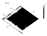
図4は、両偏波送受用アンテナ1の地導体板10における面電流密度(2.44GHz)の分布状態を表した説明図である。
図4に示されるように、地導体板10に発生している、或る特定位相における面電流密度は、地導体板10のエッジ(外周辺近傍)に高周波電流が乗るだけである。これは、図示していない他の位相を含めたいずれの位相においても同様である。
即ち、本実施形態の両偏波送受用アンテナ1によれば、地導体板10の中央部分に高周波電流が乗ることはない。
従って、地導体板10の一辺の長さをLとした場合、中央のL/2若しくは3L/5四方の範囲、又はその近傍領域の範囲を切り取ることが可能である。これにより、両偏波送受用アンテナ1の重量を軽くすることが可能である。
また、地導体板10の当該中央領域に高周波電流が乗らないことから、当該領域内に電子回路等を配設することも可能である。上述のように中央領域を切り取って、切り取り領域内に電子回路等を配設することも可能である。
FIG. 4 is an explanatory diagram showing a distribution state of a surface current density (2.44 GHz) on the
As shown in FIG. 4, the surface current density in a specific phase generated in the
That is, according to the dual-polarization transmitting / receiving antenna 1 of the present embodiment, the high-frequency current does not ride on the central portion of the
Therefore, when the length of one side of the
In addition, since a high-frequency current does not enter the central region of the
以上説明したように、本実施形態の両偏波送受用アンテナ1によれば、地導体板10の直交する2辺11、12のそれぞれに対向させて、実質同一の共振周波数に形成された逆Fアンテナ20とダイポールアンテナ30を実質直交するように配設する。
そして、逆Fアンテナ20の開放端側とダイポールアンテナ30の開放端側のそれぞれに共通の給電部40のEM給電部41を対向配置することで、両アンテナ20、30に対して電磁的な給電を1点で行う。
このように本実施形態の両偏波送受用アンテナ1では、EM給電による1点給電方式を採用することで、給電部と高周波回路を簡略化することができ、より簡単な構成で垂直偏波と水平偏波の送受信が可能な両偏波送受用アンテナが得られる。
また、第1線状アンテナとして逆Fアンテナを使用することで、両偏波送受用アンテナを小型化することができ、また、地導体板の中央部を切り取ったり電子回路を設けることができる。
As described above, according to the dual-polarized wave transmitting / receiving antenna 1 of the present embodiment, the two
By disposing the
As described above, in the dual-polarization transmission / reception antenna 1 according to the present embodiment, by adopting the one-point feeding method using the EM feeding, the feeding unit and the high-frequency circuit can be simplified, and the vertically polarized wave can be simplified. And a dual polarization transmitting / receiving antenna capable of transmitting and receiving horizontal polarized waves.
Further, by using the inverted F antenna as the first linear antenna, the size of the antenna for transmitting and receiving both polarized waves can be reduced, and the center of the ground conductor plate can be cut off or an electronic circuit can be provided.
図5は、両偏波送受用アンテナ1の配置と偏波の入れ替えについて表した説明図である。
なお、図9(a)を除き、図5以下の図面では、各アンテナの形状や配置状態を説明するものなので、簡略化して表している。
図5(a)は、図1で説明した両偏波送受用アンテナ1と同じで、基準となる両偏波送受用アンテナ1を表している。
この図5(a)の基準配置した両偏波送受用アンテナ1に対して、図5(b)の左右対称に配置(縦中心軸線に対して裏表を反転)した場合でも、図5(c)の上下対称に配置(横中心軸線に対して裏表を反転)した場合でも、同様に両偏波送受用アンテナとして動作する。すなわち、地導体板10に対するいずれの向きで配置したとしても、配置に対してZ軸方向の両偏波送受用アンテナとして使用することができる。
FIG. 5 is an explanatory diagram showing the arrangement of the dual-polarized wave transmitting / receiving antenna 1 and the exchange of the polarized waves.
Except for FIG. 9A, the drawings after FIG. 5 illustrate the shape and arrangement of each antenna, and are therefore simplified.
FIG. 5A shows a dual-polarization transmitting / receiving antenna 1 which is the same as the dual-polarization transmitting / receiving antenna 1 described with reference to FIG.
Even if the two-polarized transmission / reception antenna 1 arranged as a reference in FIG. 5A is symmetrically arranged in FIG. 5B (inverted with respect to the vertical center axis), FIG. ) (Upside down with respect to the horizontal central axis), the antenna operates similarly as a dual-polarized transmission / reception antenna. That is, even if the antenna is arranged in any direction with respect to the
次に、両偏波送受用アンテナ1における変形例について説明する。
図6は、両偏波送受用アンテナ1の変形例の構成を表したものである。
図6(a)は、図1で説明した両偏波送受用アンテナ1の2組みを、点対称(反対側)に配置したものである。
すなわち、1つの地導体板10に対し、逆Fアンテナ20aとダイポールアンテナ30aと給電部40aからなる第1両偏波送受用アンテナ1aと、逆Fアンテナ20bとダイポールアンテナ30bと給電部40bからなる第2両偏波送受用アンテナ1bの2組を点対称に配置したものである。
この変形例によれば、両両偏波送受用アンテナ1a、1bの共振周波数(例えば、2.44GHz)を共通にすることで、実施形態で説明した両偏波送受用アンテナ1に比べて利得を向上させることができる。
一方、第1両偏波送受用アンテナ1aと第2両偏波送受用アンテナ1bを、それぞれ異なる周波数帯のアンテナとすることで、2周波対応の両偏波送受用アンテナを提供することができる。例えば、第1両偏波送受用アンテナ1aを2.44GHz帯とし、第2両偏波送受用アンテナ1bを5.2GHz帯とする。
Next, a modified example of the dual polarization transmitting / receiving antenna 1 will be described.
FIG. 6 shows a configuration of a modified example of the dual polarization transmitting / receiving antenna 1.
FIG. 6A shows two sets of the dual-polarization transmitting / receiving antenna 1 described in FIG. 1 arranged in point symmetry (opposite side).
That is, for one
According to this modified example, by making the resonance frequency (for example, 2.44 GHz) of the dual polarization transmission / reception antennas 1a and 1b common, the gain is higher than that of the dual polarization transmission / reception antenna 1 described in the embodiment. Can be improved.
On the other hand, by using the first dual-polarization transmitting / receiving antenna 1a and the second dual-polarization transmitting / receiving antenna 1b as antennas of different frequency bands, a dual-polarization transmitting / receiving antenna corresponding to two frequencies can be provided. . For example, the first dual-polarized wave transmitting / receiving antenna 1a is in the 2.44 GHz band, and the second dual-polarized wave transmitting / receiving antenna 1b is in the 5.2 GHz band.
なお、2組の両偏波送受用アンテナを図6(b)に示したように配置した場合、垂直偏波同士、水平偏波同士が相殺してしまうため、採用できない配置であるが、2つの組をスイッチングなどで異なるタイミングで給電を行えば、両偏波送受信が可能となる。また、20aと30a、20bと30bの素子寸法を制御し、各々の共振周波数を変えれば、2周波共用で両偏波送受信を実現するアンテナ系の構築が可能となる。 When two sets of dual-polarized wave transmitting and receiving antennas are arranged as shown in FIG. 6B, the vertically polarized waves and the horizontally polarized waves cancel each other out. If two sets are fed at different timings by switching or the like, transmission and reception of both polarized waves can be performed. Also, by controlling the element dimensions of 20a and 30a and 20b and 30b and changing the respective resonance frequencies, it becomes possible to construct an antenna system that realizes dual-polarization transmission and reception using two frequencies.
図7は、他種類のアンテナを組み合わせた各変形例を表したものである。
第1線状アンテナと第2線状アンテナとしては、それぞれ逆Fアンテナ、逆Lアンテナ、ダイポールアンテナの何れかを選択することが可能であり、その選択可能な組み合わせを図7で表している。なお図面では、逆Fアンテナと逆Lアンテナを簡略して逆F、逆Lと表記し、ダイポールアンテナをダイポールと簡略して表記している。
図7(a)〜(c)は、第1の線状アンテナ、第2の線状アンテナとして共にλ/4型のアンテナを配置したものである。
図7(a)は、開放端側が地導体板10の同一の角側に来るように、2つの逆Fアンテナを配置した、逆F+逆F型の両偏波送受用アンテナである。
一方の逆Fアンテナについては、図1で説明したダイポールアンテナ30の屈曲部32と同様に、EM給電部41と対向するように開放端側を屈曲形成している。このEM給電部41に対向させるために一方のアンテナの開放端側を屈曲形成することについては図7(b)〜(e)も同様である。
FIG. 7 shows a modification example in which other types of antennas are combined.
As the first linear antenna and the second linear antenna, any one of an inverted F antenna, an inverted L antenna, and a dipole antenna can be selected, and the selectable combinations are shown in FIG. In the drawings, the inverted F antenna and the inverted L antenna are simply denoted as inverted F and L, and the dipole antenna is simply denoted as a dipole.
FIGS. 7A to 7C show a case where a λ / 4 type antenna is arranged as both the first linear antenna and the second linear antenna.
FIG. 7A shows an inverted-F + inverted-F dual-polarization transmitting / receiving antenna in which two inverted-F antennas are arranged such that the open end is on the same corner of the
One inverted-F antenna has an open end bent so as to face the
図7(b)は、実施形態のダイポールアンテナ30に変えて逆Lアンテナを配置した、逆F+逆L型の両偏波送受用アンテナの例である。この例においても、給電部40側を開放端側として屈曲形成し、反対側に短絡部を設けている。
図7(c)は、実施形態の逆Fアンテナ20と、ダイポールアンテナ30の両者を、共に逆Lアンテナに変えて配置した、逆L+逆L型の両偏波送受用アンテナである。
図7(a)〜(c)共に、両アンテナの短絡部のそれぞれが、地導体板10に対して対角線上に位置するように配置されている。
FIG. 7B is an example of an inverted F + inverse L type dual polarization transmitting / receiving antenna in which an inverted L antenna is arranged instead of the
FIG. 7C shows an inverted-L + inverted-L dual-polarization transmitting / receiving antenna in which both the
7A to 7C, the short-circuit portions of both antennas are arranged so as to be located diagonally with respect to the
図7(d)は、実施形態の逆Fアンテナ20に変えて逆Lアンテナを配置した、逆L+ダイポール型の両偏波送受用アンテナの例である。この変形例では、実施形態と同様にλ/4型とλ/2型のアンテナ使用している。
FIG. 7D shows an example of an inverted L + dipole type dual polarization transmitting / receiving antenna in which an inverted L antenna is arranged instead of the
なお、図7(a)〜(d)で説明した各変形例にかかる両偏波送受用アンテナでは、いずれもλ/4型のアンテナ(逆Fアンテナ、逆Lアンテナ)を使用しているため、地導体板10が必要になる。
そして、実施形態の両偏波送受用アンテナ1に対して図4で説明したと同様に、図7(a)〜(d)の各変形例における地導体板10の中央部にも高周波電流が乗ることはない。従って、これらの変形例においても、地導体板10の中央部を切り取ったり、電子回路を配設したりすることができる。
Note that, in each of the dual-polarization transmitting / receiving antennas according to the modified examples described with reference to FIGS. 7A to 7D, a λ / 4 type antenna (an inverted F antenna, an inverted L antenna) is used. , The
In the same manner as described with reference to FIG. 4 for the dual-polarization transmitting / receiving antenna 1 of the embodiment, a high-frequency current is also applied to the center of the
図7(e)は、実施形態の逆Fアンテナ20に変えて、ダイポールアンテナを配置した、ダイポール+ダイポール型の両偏波送受用アンテナの例である。
この変形例によれば、共にλ/2型のアンテナであるため、地導体板10が不要になり、軽量の両偏波送受用アンテナとすることが可能である。
FIG. 7E is an example of a dipole + dipole type dual polarization transmitting / receiving antenna in which a dipole antenna is arranged in place of the
According to this modified example, since both are λ / 2 type antennas, the
以上、図7(a)〜(e)に示した各変形例の両偏波送受用アンテナについて説明したが、その配置を図5で説明したように任意の配置を選択することができる。
また、図6とその変形(多周波)で説明したように、第1両偏波送受用アンテナ1a、第2両偏波送受用アンテナ1bの、いずれも図7(a)〜(e)のうちの任意の1つを選択することも可能である。
As described above, the dual-polarized wave transmitting / receiving antenna according to each of the modified examples shown in FIGS. 7A to 7E has been described. However, an arbitrary arrangement can be selected as described with reference to FIG.
As described in FIG. 6 and its modification (multi-frequency), both the first dual-polarization transmitting / receiving antenna 1a and the second dual-polarization transmitting / receiving antenna 1b are shown in FIGS. 7 (a) to 7 (e). It is also possible to select any one of them.
図8は、両偏波送受用アンテナにおける、給電部分の形状を変更した変形例についての説明図である。
図1で説明した実施形態の両偏波送受用アンテナ1では、逆Fアンテナ20のアンテナ主部21と、ダイポールアンテナ30の屈曲部32とが、ほぼ同一直線上に配置されることで、直線状のEM給電部41を両アンテナの開放端側に対向配置する場合について説明した。
図8(a)では、ダイポールアンテナ30c(第2線状アンテナ)の開放端側を屈曲せずに、直線形状のアンテナ主部31cだけで構成し、その代わりにEM給電部41cを屈曲させることで、ダイポールアンテナ30cの開放端に対向配置したものである。
図8(b)では、逆Fアンテナ20のアンテナ主部21と、ダイポールアンテナ30dの屈曲部32とを同一線上に配置せずに、所定間隔を開けて平行に配置すると共に、当該所定間隔の内にEM給電部41dを配置したものである。これにより、図8の例では、EM給電部41dの地導体板10と対向する側を内側、反対側を外側とした場合に、逆Fアンテナ20のアンテナ主部21はEM給電部41dの外側と対向し、ダイポールアンテナ30dの屈曲部はEM給電部41dの内側と対向することになる。
なお、図8(a)、(b)に示した、両アンテナ(第1線状アンテナと第2線状アンテナ)の開放端側の形状及びEM給電部の形状と配置については、図6、図7で説明した各変形例、及び、この後に説明する変形例についても同様に適用が可能である。
FIG. 8 is an explanatory diagram of a modified example in which the shape of the power supply portion in the dual-polarized wave transmitting / receiving antenna is changed.
In the dual polarization transmitting / receiving antenna 1 of the embodiment described with reference to FIG. 1, the antenna
In FIG. 8A, the open end side of the
In FIG. 8B, the antenna
The shapes of the open ends of the two antennas (the first linear antenna and the second linear antenna) and the shape and arrangement of the EM feeder shown in FIGS. 8A and 8B are shown in FIG. The modifications described with reference to FIG. 7 and the modifications described later can be similarly applied.
図9は、両偏波送受用アンテナ1の他の変形例の構成を表した説明図である。
図9(a)は、逆Fアンテナ20、ダイポールアンテナ30、給電部40を立体構造にした両偏波送受用アンテナの変形例である。
図9(a)に示すように、地導体板10と接続されている逆Fアンテナ20eの第1短絡部22eと第2短絡部23eを地導体板10に対して直角に折り曲げることで、図1におけるZ−Y平面上に形成している。
ダイポールアンテナ30eについては、上述したように電圧がゼロである中央部又はその近傍領域を短絡部33eで接続し、当該短絡部33eを地導体板10に対して直角に折り曲げることで、Z−X平面上に形成している。
また、逆Fアンテナ20eとダイポールアンテナ30eを直角方向に折り曲げたことに対応して、給電部40eについても同様に、地導体板10に対して直交するように給電ライン42eを立体構造とし、Z−Y平面上に形成している。
なお、ダイポールアンテナ30eの屈曲部32eについては、立体構造にしたことに伴い、図1で説明した実施形態に比べて長さが短くなっている。この屈曲部32eを短くしたことに対応して、ダイポールアンテナ30eのEM給電部41eとの対向する長さが短くならないようにするため、EM給電部41eのダイポールアンテナ30e側の端部43eを辺12(図1参照)方向に屈曲させている。
この図9(a)に示した変形例によれば、両偏波送受用アンテナ全体の配設面積を小さくすることができる。
FIG. 9 is an explanatory diagram showing a configuration of another modified example of the dual-polarized wave transmitting / receiving antenna 1.
FIG. 9A is a modified example of the dual-polarized wave transmitting / receiving antenna in which the
As shown in FIG. 9A, the first short-
As for the
In addition, in response to bending the
Note that the
According to the modified example shown in FIG. 9A, the arrangement area of the entire dual polarization transmitting / receiving antenna can be reduced.
一方、図9(b)の変形例では、図1で説明した両偏波送受用アンテナ1の逆Fアンテナ20とダイポールアンテナ30の更に外側に、第2の両偏波送受用アンテナとして、逆Lアンテナ50とダイポールアンテナ60を配設したものである。
図9(b)に示すように、逆Lアンテナ50は、逆Fアンテナ20の第2短絡部23の延長線上に、短絡部(一般の逆Lアンテナにおける給電ライン部分)を形成する。
なお、給電部40については、2組の両偏波送受用アンテナに共通して電磁的に給電するようにしている。
この変形例によれば、多周波の両偏波送受用アンテナを提供することができる。
On the other hand, in the modified example of FIG. 9B, the
As shown in FIG. 9B, the inverted-
Note that the
According to this modified example, it is possible to provide a multi-polarized dual-polarized wave transmitting / receiving antenna.
以上本実施形態の両偏波送受用アンテナ1とその変形例について説明したが、更に各種の変形をすることが可能である。
例えば、説明した各両偏波送受用アンテナを、ガラスエポキシ樹脂等の比誘電率が高い基板上に形成するようにしてもよい。これにより、同一サイズを基準にした場合の波長が短縮することを利用し、同一波長(同一共振周波数)で小型化した両偏波送受用アンテナを提供することが可能になる。
Although the dual-polarized wave transmitting / receiving antenna 1 of the present embodiment and its modified examples have been described above, various modifications can be made.
For example, each of the above-described antennas for transmitting and receiving both polarized waves may be formed on a substrate having a high relative dielectric constant such as a glass epoxy resin. This makes it possible to provide a miniaturized dual-polarized transmission / reception antenna at the same wavelength (the same resonance frequency), utilizing the fact that the wavelength is shortened based on the same size.
また、説明した実施形態及び変形例では、いずれも単層の両偏波送受用アンテナについて説明したが、ガラスエポキシ樹脂等の高比誘電率基板の上に説明した実施形態、変形例の各両偏波送受用アンテナを配設した組を1層のアンテナ層とした場合に、当該アンテナ層を多層化(例えば2層、4層、8層)するようにしてもよい。
この場合、各層の両偏波送受用アンテナにおける、地導体板10、逆Fアンテナ20、ダイポールアンテナ30、及び、給電部40の各部については、相互にビア接続する。但し、給電部40の給電ライン42については、1層とし、何れか1の層のEM給電部41に接続する構成としてもよい。
なお、多層化する場合、最下層の高比誘電率基板を省略することで、アンテナをn層、高比誘電率基板をn−1層とすることで、多層化した両偏波送受用アンテナの両外側面にアンテナ層がくるように配置してもよい。
In the embodiments and the modified examples described above, the single-layered dual-polarization transmitting / receiving antenna has been described. However, each of the embodiments and the modified examples described on the high relative permittivity substrate such as a glass epoxy resin. When the set in which the polarized wave transmitting / receiving antennas are provided is a single antenna layer, the antenna layers may be multi-layered (for example, two layers, four layers, or eight layers).
In this case, the
In the case of multi-layered transmission / reception antennas having a multilayer structure, the antenna having n layers and the high-permittivity substrate having n-1 layers is omitted by omitting the lowermost high-permittivity substrate. May be arranged so that the antenna layers are located on both outer side surfaces.
また、説明した実施形態、変形例では、いずれも開放端を除き直線状態のアンテナエレメント形状について説明したが、直線形状には限られない。
例えば、ミアンダ形状やヘリカル形状、更に端部屈曲形状(先端折れ曲げ形状)とすることも可能である。
Further, in the above-described embodiments and modified examples, the antenna element shape in a linear state except for the open end has been described, but is not limited to the linear shape.
For example, a meander shape, a helical shape, and an end bent shape (a bent end shape) are also possible.
1 両偏波送受用アンテナ
10 地導体板
11、12 辺
20 逆Fアンテナ
21 アンテナ主部
22 第1短絡部
23 第2短絡部
30 ダイポールアンテナ
31 アンテナ主部
32 屈曲部
40 給電部
41 EM給電部
42 給電ライン
DESCRIPTION OF SYMBOLS 1 Dual-polarized wave transmitting / receiving
Claims (12)
少なくとも1の開放端を有する第1線状アンテナと、
少なくとも1の開放端を有し、当該開放端側と前記第1線状アンテナの開放端側とが所定間隔で、前記第1線状アンテナとほぼ直交状態に配設され、前記第1線状アンテナの共振周波数と実質同一の共振周波数に形成された第2線状アンテナと、
前記第1線状アンテナの前記開放端側、及び前記第2線状アンテナの前記開放端側のそれぞれと、所定間隔をおいて対向配置されることで、前記第1線状アンテナ及び前記第2線状アンテナに電磁的に接続されるEM給電部と、
前記EM給電部と電気的に接続され、前記EM給電部を介して前記第1線状アンテナ及び前記第2線状アンテナに給電する給電ラインと、を具備し、
前記第1線状アンテナと前記第2線状アンテナは、前記地導体板の外縁に沿って前記地導体板の外側に配設されている、
ことを特徴とする両偏波送受用アンテナ。 Ground conductor plate,
A first linear antenna having at least one open end;
The first linear antenna has at least one open end, and the open end side and the open end side of the first linear antenna are arranged at a predetermined interval in a state substantially orthogonal to the first linear antenna; A second linear antenna formed at a resonance frequency substantially the same as the resonance frequency of the antenna;
The first linear antenna and the second linear antenna are disposed opposite to each other at a predetermined interval from the open end side of the first linear antenna and the open end side of the second linear antenna, respectively. An EM feeder electromagnetically connected to the linear antenna;
A power supply line that is electrically connected to the EM power supply unit and supplies power to the first linear antenna and the second linear antenna via the EM power supply unit;
The first linear antenna and the second linear antenna are disposed outside the ground conductor plate along an outer edge of the ground conductor plate,
An antenna for dual polarization transmission and reception.
ことを特徴とする請求項1に記載の両偏波送受用アンテナ。The dual-polarized wave transmitting / receiving antenna according to claim 1, wherein:
ことを特徴とする請求項1に記載の両偏波送受用アンテナ。The dual-polarized wave transmitting / receiving antenna according to claim 1, wherein:
前記第2線状アンテナは、逆Fアンテナ、逆Lアンテナ、及び、ダイポールアンテナのうちの何れか1のアンテナであり、
前記逆Fアンテナは、前記地導体板の端面とほぼ平行に配設され、開放端側が前記EM給電部と対向配置されるアンテナ主部と、前記アンテナ主部の前記開放端側の反対側端部と前記地導体板とを短絡する第1短絡部と、前記アンテナ主部の前記第1短絡部よりも開放側において、前記アンテナ主部と前記地導体板とを短絡する第2短絡部とを有し、
前記逆Lアンテナは、前記地導体板の端面とほぼ平行に配設され、前記開放端側が前記EM給電部と対向配置されるアンテナ主部と、前記アンテナ主部の前記開放端側の反対側端部と前記地導体板とを短絡する第1短絡部とを有する、
ことを特徴とする請求項1、請求項2、又は請求項3に記載の両偏波送受用アンテナ。 The first linear antenna is any one of an inverted F antenna, an inverted L antenna, and a dipole antenna,
The second linear antenna is any one of an inverted F antenna, an inverted L antenna, and a dipole antenna,
The inverted-F antenna is disposed substantially in parallel with an end face of the ground conductor plate, and has an open end side facing the EM feed unit and an end opposite to the open end of the main antenna part. A first short-circuit portion that short-circuits the portion and the ground conductor plate; and a second short-circuit portion that short-circuits the antenna main portion and the ground conductor plate on the open side of the antenna main portion with respect to the first short-circuit portion. Has,
The inverted L antenna is disposed substantially in parallel with an end surface of the ground conductor plate, and has an open end side opposed to the EM feed unit and an opposite side of the open end side of the antenna main part. Having a first short-circuit portion that short-circuits the end portion and the ground conductor plate,
The dual- polarized wave transmitting / receiving antenna according to claim 1 , 2 or 3 , wherein
ことを特徴とする請求項4に記載の両偏波送受用アンテナ。 The second linear antenna is a different type of antenna from the first linear antenna,
The dual-polarized wave transmitting / receiving antenna according to claim 4 , wherein:
ことを特徴とする請求項1から請求項5のうちのいずれか1の請求項に記載の両偏波送受用アンテナ。 The EM feed unit is disposed to face a side surface of the open end side end of the first linear antenna and a side surface of the open end side end of the second linear antenna at a predetermined interval,
The dual-polarized wave transmitting / receiving antenna according to any one of claims 1 to 5 , characterized in that:
ことを特徴とする請求項6に記載の両偏波送受用アンテナ。 The end of the first linear antenna on the open end side and the end of the second linear antenna on the open end side are arranged on the same line or in parallel with each other.
7. The dual-polarized wave transmitting / receiving antenna according to claim 6 , wherein:
ことを特徴とする請求項1から請求項7のうちのいずれか1の請求項に記載の両偏波送受用アンテナ。 The ground conductor plate has a central region cut out,
The dual-polarized wave transmitting / receiving antenna according to any one of claims 1 to 7 , wherein:
ことを特徴とする請求項1から請求項8のうちのいずれか1の請求項に記載の両偏波送受用アンテナ。 The resonance frequency f of the dual-polarized wave transmitting / receiving antenna is f = 2.44 GHz;
The dual-polarized wave transmitting / receiving antenna according to any one of claims 1 to 8 , wherein:
前記第1線状アンテナと前記第2線状アンテナは、前記高比誘電体基板上に形成されている、
ことを特徴とする請求項1から請求項9のうちのいずれか1の請求項に記載の両偏波送受用アンテナ。 Equipped with a high relative dielectric substrate,
The first linear antenna and the second linear antenna are formed on the high relative dielectric substrate,
The dual-polarized wave transmitting / receiving antenna according to any one of claims 1 to 9 , wherein:
ことを特徴とする請求項1から請求項10のうちのいずれか1の請求項に記載の両偏波送受用アンテナ。 Each of the first linear antenna, the second linear antenna, and the EM power supply unit is formed of a plurality of layers connected to each other via,
The dual-polarized wave transmitting / receiving antenna according to any one of claims 1 to 10 , wherein:
ことを特徴とする請求項1から請求項11のうちのいずれか1の請求項に記載の両偏波送受用アンテナ。 In the first linear antenna and the second linear antenna, the shape of the antenna element portion is a linear shape, a meander shape, a helical shape, or a bent end shape.
The dual-polarized wave transmitting / receiving antenna according to any one of claims 1 to 11 , characterized in that:
Priority Applications (2)
| Application Number | Priority Date | Filing Date | Title |
|---|---|---|---|
| JP2017063558A JP6678616B2 (en) | 2017-03-28 | 2017-03-28 | Dual polarized antenna |
| PCT/JP2018/011374 WO2018180877A1 (en) | 2017-03-28 | 2018-03-22 | Dual polarized wave transmission/reception antenna |
Applications Claiming Priority (1)
| Application Number | Priority Date | Filing Date | Title |
|---|---|---|---|
| JP2017063558A JP6678616B2 (en) | 2017-03-28 | 2017-03-28 | Dual polarized antenna |
Publications (3)
| Publication Number | Publication Date |
|---|---|
| JP2018166294A JP2018166294A (en) | 2018-10-25 |
| JP2018166294A5 JP2018166294A5 (en) | 2018-12-06 |
| JP6678616B2 true JP6678616B2 (en) | 2020-04-08 |
Family
ID=63675649
Family Applications (1)
| Application Number | Title | Priority Date | Filing Date |
|---|---|---|---|
| JP2017063558A Active JP6678616B2 (en) | 2017-03-28 | 2017-03-28 | Dual polarized antenna |
Country Status (2)
| Country | Link |
|---|---|
| JP (1) | JP6678616B2 (en) |
| WO (1) | WO2018180877A1 (en) |
Families Citing this family (2)
| Publication number | Priority date | Publication date | Assignee | Title |
|---|---|---|---|---|
| JP6820071B1 (en) * | 2019-09-26 | 2021-01-27 | Necプラットフォームズ株式会社 | Wireless communication device and wireless communication method |
| JP6984951B2 (en) * | 2020-04-22 | 2021-12-22 | Necプラットフォームズ株式会社 | Antenna device and wireless communication device |
Family Cites Families (10)
| Publication number | Priority date | Publication date | Assignee | Title |
|---|---|---|---|---|
| JP3169325B2 (en) * | 1995-08-14 | 2001-05-21 | 東洋通信機株式会社 | Array antenna |
| JP3180683B2 (en) * | 1996-09-20 | 2001-06-25 | 株式会社村田製作所 | Surface mount antenna |
| JP3721168B2 (en) * | 2003-02-25 | 2005-11-30 | Necアクセステクニカ株式会社 | Antenna equipment for small radio |
| WO2004084344A1 (en) * | 2003-03-18 | 2004-09-30 | Sony Ericsson Mobile Communications Ab | Compact diversity antenna |
| WO2006031364A2 (en) * | 2004-09-09 | 2006-03-23 | Bae Systems Information And Electronic Systems Integration, Inc. | Polarization agile antenna |
| JP2007159064A (en) * | 2005-12-08 | 2007-06-21 | Sony Corp | Antenna, radio device using same and electronic apparatus |
| JP2009076960A (en) * | 2007-09-18 | 2009-04-09 | Samsung Electronics Co Ltd | Antenna system |
| JP5098588B2 (en) * | 2007-11-16 | 2012-12-12 | 大日本印刷株式会社 | Non-contact type IC tag and method of manufacturing non-contact type IC tag |
| JP2011082951A (en) * | 2009-09-14 | 2011-04-21 | Nagasaki Univ | Inverse-l shaped antenna |
| WO2014013840A1 (en) * | 2012-07-20 | 2014-01-23 | 旭硝子株式会社 | Antenna device and wireless device provided with same |
-
2017
- 2017-03-28 JP JP2017063558A patent/JP6678616B2/en active Active
-
2018
- 2018-03-22 WO PCT/JP2018/011374 patent/WO2018180877A1/en active Application Filing
Also Published As
| Publication number | Publication date |
|---|---|
| WO2018180877A1 (en) | 2018-10-04 |
| JP2018166294A (en) | 2018-10-25 |
Similar Documents
| Publication | Publication Date | Title |
|---|---|---|
| CN102414914B (en) | Balanced metamaterial antenna device | |
| US11095040B2 (en) | Antenna and mimo antenna | |
| CN104157968B (en) | New concept broadband circularly polarized antenna | |
| TWI657620B (en) | Antenna directivity control system and wireless device including the same | |
| US10103440B2 (en) | Stripline coupled antenna with periodic slots for wireless electronic devices | |
| US20130314286A1 (en) | Cross-dipole antenna configurations | |
| GB2551212A (en) | An Antenna system for a portable device | |
| EP3172797B1 (en) | Slot antenna | |
| Huang et al. | A low-profile, single-ended and dual-polarized patch antenna for 5G application | |
| CN104871367A (en) | Multiband antenna | |
| GB2542257B (en) | Reconfigurable antenna for incorporation in the hinge of a laptop computer | |
| JP2012147263A (en) | Antenna module and radio communication equipment | |
| JP6678617B2 (en) | Circularly polarized antenna | |
| US20040100409A1 (en) | Antenna and dielectric substrate for antenna | |
| US20130194147A1 (en) | Antenna device | |
| JP7028212B2 (en) | Antenna device | |
| JP6678616B2 (en) | Dual polarized antenna | |
| WO2011024961A1 (en) | Antenna | |
| US11050151B2 (en) | Multi-band antenna | |
| JP2007124346A (en) | Antenna element and array type antenna | |
| JP5425019B2 (en) | Antenna device | |
| Schulz et al. | A broadband stacked patch antenna with enhanced antenna gain by an optimized ellipsoidal reflector for X-band applications | |
| US11063357B2 (en) | Dual-band antenna for global positioning system | |
| CN113826282A (en) | Dual-polarized antenna powered by displacement series connection | |
| JP2002050918A (en) | Chip antenna |
Legal Events
| Date | Code | Title | Description |
|---|---|---|---|
| A521 | Request for written amendment filed |
Free format text: JAPANESE INTERMEDIATE CODE: A523 Effective date: 20181012 |
|
| A621 | Written request for application examination |
Free format text: JAPANESE INTERMEDIATE CODE: A621 Effective date: 20181012 |
|
| A131 | Notification of reasons for refusal |
Free format text: JAPANESE INTERMEDIATE CODE: A131 Effective date: 20190726 |
|
| A521 | Request for written amendment filed |
Free format text: JAPANESE INTERMEDIATE CODE: A523 Effective date: 20190920 |
|
| TRDD | Decision of grant or rejection written | ||
| A01 | Written decision to grant a patent or to grant a registration (utility model) |
Free format text: JAPANESE INTERMEDIATE CODE: A01 Effective date: 20200228 |
|
| A61 | First payment of annual fees (during grant procedure) |
Free format text: JAPANESE INTERMEDIATE CODE: A61 Effective date: 20200317 |
|
| R150 | Certificate of patent or registration of utility model |
Ref document number: 6678616 Country of ref document: JP Free format text: JAPANESE INTERMEDIATE CODE: R150 |
|
| R250 | Receipt of annual fees |
Free format text: JAPANESE INTERMEDIATE CODE: R250 |
|
| R250 | Receipt of annual fees |
Free format text: JAPANESE INTERMEDIATE CODE: R250 |