WO2018180877A1 - Dual polarized wave transmission/reception antenna - Google Patents
Dual polarized wave transmission/reception antenna Download PDFInfo
- Publication number
- WO2018180877A1 WO2018180877A1 PCT/JP2018/011374 JP2018011374W WO2018180877A1 WO 2018180877 A1 WO2018180877 A1 WO 2018180877A1 JP 2018011374 W JP2018011374 W JP 2018011374W WO 2018180877 A1 WO2018180877 A1 WO 2018180877A1
- Authority
- WO
- WIPO (PCT)
- Prior art keywords
- antenna
- dual
- linear
- reception
- inverted
- Prior art date
Links
Images

Classifications
-
- H—ELECTRICITY
- H01—ELECTRIC ELEMENTS
- H01Q—ANTENNAS, i.e. RADIO AERIALS
- H01Q21/00—Antenna arrays or systems
- H01Q21/06—Arrays of individually energised antenna units similarly polarised and spaced apart
-
- H—ELECTRICITY
- H01—ELECTRIC ELEMENTS
- H01Q—ANTENNAS, i.e. RADIO AERIALS
- H01Q21/00—Antenna arrays or systems
- H01Q21/24—Combinations of antenna units polarised in different directions for transmitting or receiving circularly and elliptically polarised waves or waves linearly polarised in any direction
-
- H—ELECTRICITY
- H01—ELECTRIC ELEMENTS
- H01Q—ANTENNAS, i.e. RADIO AERIALS
- H01Q9/00—Electrically-short antennas having dimensions not more than twice the operating wavelength and consisting of conductive active radiating elements
- H01Q9/04—Resonant antennas
-
- H—ELECTRICITY
- H01—ELECTRIC ELEMENTS
- H01Q—ANTENNAS, i.e. RADIO AERIALS
- H01Q9/00—Electrically-short antennas having dimensions not more than twice the operating wavelength and consisting of conductive active radiating elements
- H01Q9/04—Resonant antennas
- H01Q9/16—Resonant antennas with feed intermediate between the extremities of the antenna, e.g. centre-fed dipole
-
- H—ELECTRICITY
- H01—ELECTRIC ELEMENTS
- H01Q—ANTENNAS, i.e. RADIO AERIALS
- H01Q9/00—Electrically-short antennas having dimensions not more than twice the operating wavelength and consisting of conductive active radiating elements
- H01Q9/04—Resonant antennas
- H01Q9/30—Resonant antennas with feed to end of elongated active element, e.g. unipole
- H01Q9/42—Resonant antennas with feed to end of elongated active element, e.g. unipole with folded element, the folded parts being spaced apart a small fraction of the operating wavelength
Definitions
- the present invention relates to a dual-polarized transmission / reception antenna, and relates to an antenna that transmits and receives vertical polarization and horizontal polarization.
- Non-Patent Documents 1 and 2 When transmitting and receiving two polarizations of vertical polarization and horizontal polarization, two feeding points corresponding to both polarizations are required.
- a polarization sharing antenna As a technique for transmitting and receiving such two polarized waves, a polarization sharing antenna has been proposed (see Non-Patent Documents 1 and 2).
- This dual-polarized antenna can transmit and receive two polarizations of vertical polarization and horizontal polarization at the same frequency, or can transmit and receive simultaneously, and is used in fields such as satellite communication and remote sensing.
- the object of the present invention is to enable transmission and reception of vertically polarized waves and horizontally polarized waves with a simpler configuration.
- the first linear antenna having at least one open end, and at least one open end, the open end side and the open end side of the first linear antenna. Are arranged at a predetermined interval and substantially orthogonal to the first linear antenna, and are formed at a resonance frequency substantially the same as the resonance frequency of the first linear antenna, and the first linear antenna.
- the first linear antenna and the second linear antenna are arranged to be opposed to each of the open end side of the linear antenna and the open end side of the second linear antenna at a predetermined interval.
- An electromagnetic coupling type power supply unit (EM power supply unit) that is electromagnetically connected to the EM power supply unit, and the first linear antenna and the second linear antenna that are electrically connected to the EM power supply unit via the EM power supply unit
- the antenna main part to be arranged the first short-circuiting part that short-circuits the opposite end part of the antenna main part on the open end side and the ground conductor plate, and the first mains short-circuiting part of the antenna main part that is open.
- the antenna is an inverted F antenna having a second short-circuit portion that short-circuits the antenna main portion and the ground conductor plate.
- the first linear antenna is disposed substantially parallel to an end surface of the ground conductor plate, and an open end side faces the EM power feeding portion.
- a dual-polarized transmission / reception antenna according to claim 1 is provided.
- the first linear antenna is a dipole antenna, and both of the claims according to any one of claims 1 to 3 are characterized.
- a polarized wave transmitting / receiving antenna is provided.
- the second linear antenna is a dipole antenna, an inverted F antenna, or an inverted L antenna.
- a dual-polarized transmission / reception antenna according to any one of the claims is provided.
- a dual-polarized transmission / reception antenna according to claim 1 is provided.
- a dual-polarized transmission / reception antenna according to any one of claims 1 to 6 is provided.
- each of the first linear antenna, the second linear antenna, and the EM feeder is formed of a plurality of layers connected to each other via.
- a dual-polarized transmission / reception antenna according to any one of claims 1 to 7 is provided.
- the shape of the antenna element portion is a linear shape, a meander shape, a helical shape, or a bent end shape,
- the dual-polarized transmission / reception antenna according to any one of claims 1 to 8 is provided.
- the first linear antenna and the second linear antenna having substantially the same resonance frequency are orthogonally arranged, and are opposed to both open ends of the two linear antennas at a predetermined interval.
- vertical polarization and horizontal polarization can be transmitted and received with a simpler configuration.
- any two of a dipole antenna, an inverted F antenna, and an inverted L antenna whose resonance frequencies are adjusted to be substantially the same are used as the first linear shape.
- An antenna and a second linear antenna are used, and the open end sides of the two linear antennas are orthogonally arranged with a predetermined distance therebetween.
- an EM power feeding part is disposed opposite to each of the open ends of the first linear antenna and the second linear antenna at a predetermined interval, and the power feeding line is electrically connected to the EM power feeding part.
- the dual-polarized transmission / reception antenna of the present embodiment by realizing electromagnetic one-point power feeding from both open ends of two orthogonal linear antennas having substantially the same resonance frequency.
- the power feeding unit and the high frequency circuit can be simplified. That is, it is possible to obtain a dual-polarized wave transmission / reception antenna that can transmit and receive vertical polarization and horizontal polarization with a simpler configuration.
- the orthogonal arrangement of the antennas is arranged in an orthogonal state, and the arrangement in the orthogonal state is not limited to a right angle in a strict sense, but an angle width that can realize a practical dual-polarized transmission / reception antenna. For example, it is set in the range of ⁇ / 2 ⁇ 10 degrees, preferably in the range of ⁇ / 2 ⁇ 5 degrees.
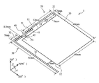
- an inverted F antenna 20 (first linear antenna) having an open end on one side of two orthogonal sides of the rectangular ground conductor plate 10 and a dipole antenna on the other side. 30 (second linear antenna) is disposed, and the EM power feeding portion 41 of the power feeding portion 40 is disposed opposite to both open ends.
- the resonant frequencies of the inverted F antenna 20 and the dipole antenna 30 are set to be substantially the same in order to obtain a dual-polarized transmission / reception antenna having a resonance frequency of 2.44 GHz.
- the opposite side of the open end side of the inverted F antenna 20 is short-circuited to the ground conductor plate 10 by the first short-circuit portion 22 and the second short-circuit portion 23.
- the dipole antenna 30 is not short-circuited to the ground conductor plate 10, the voltage at the central portion of the entire length is zero, so that it can be connected to the ground conductor plate 10 at this central portion.
- both polarization transmitting and receiving antennas can be reduced in size, and the ground conductor plate
- the center portion of the slab can be cut off or an electronic circuit can be provided.
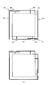
- FIG. 1 is a perspective view showing the configuration of an embodiment of a dual-polarized transmission / reception antenna.
- the dual-polarized transmission / reception antenna 1 includes a ground conductor plate 10, an inverted F antenna 20 ( ⁇ / 4 type antenna), a dipole antenna 30 ( ⁇ / 2 type antenna), and a power feeding unit. 40.
- the inverted F antenna 20 functions as a first linear antenna
- the dipole antenna 30 functions as a second linear antenna.
- the ground conductor plate 10 is formed of a rectangular sheet metal. The size of the ground conductor plate 10 is 40 mm ⁇ 40 mm.
- the inverted F antenna 20 includes an antenna main portion 21 disposed substantially parallel to the side 11 of the ground conductor plate 10, and a first short-circuit portion 22 that connects the end portion side of the antenna main portion 21 and the ground conductor plate 10. And the second short-circuit portion 23 are provided.
- the first short-circuit portion 22 connects the end portion of the antenna main portion 21 and the end portion of the ground conductor plate 10, and the second short-circuit portion 23 is substantially parallel to the antenna main portion on the open end side with respect to the first short-circuit portion 22.
- the part 21 and the ground conductor plate 10 are connected.
- the inverted F antenna 20 is formed with a line width of 1 mm as a whole, the length of the antenna main portion 21 is 32 mm, and the length of the first short-circuit portion 22 and the second short-circuit portion 23 is 4 mm (in the drawing, the antenna main portion 21 The width is added and displayed as 5 mm).
- the size of the inverted F antenna 20 of this size is 2.44 GHz band when used alone.
- the second short-circuit portion 23 is disposed with an interval of 9 mm.
- the inverted F antenna 20 of the present embodiment is integrally formed of the same material as the ground conductor plate 10, but may be formed separately and connected to each other, or may be formed of a different material. .
- the dipole antenna 30 is provided with an antenna main portion 31 disposed substantially in parallel with the other side 12 orthogonal to the side 11 of the ground conductor plate 10, and extends from the antenna main portion 31 toward the side 11.
- a bent portion 32 is provided.
- the bent portion 32 functions as an open end side facing a power supply portion 40 described later.
- the dipole antenna 30 is formed with a line width of 1 mm as a whole, the antenna main part 31 is 51 mm long, and the bent part 32 is 7 mm long.
- the distance between the antenna main portion 31 and the side 12 of the ground conductor plate 10 is 5 mm.
- the dipole antenna 30 has the same 2.44 GHz band as the inverted F antenna 20 when used alone with an overall length of 58 mm.
- the open end of the bent portion 32 and the open end of the antenna main portion 21 in the inverted F antenna 20 are arranged at a predetermined interval so that they do not come into contact with each other. In this embodiment, an interval of 7 mm (not shown) ) Is opened.
- the bent portion 32 is bent so as to face the power feeding portion 40, but is not necessary when the power feeding portion 40 side is bent as will be described later, and the antenna main portion 31 is formed longer by that amount. (See FIG. 8 (a)).
- the power feeding unit 40 is disposed in parallel with the side 11 of the ground conductor plate 10 so as to be opposed to the open end side of the inverted F antenna 20 and the open end side (bent portion 32) of the dipole antenna 30 with a predetermined distance therebetween. 41 and a power supply line 42 electrically connected to the EM power supply unit 41 at one end side. The other end side of the feed line 42 extends to the ground conductor plate 10 side, and has a feed point P1 at the end thereof.
- the power feeding unit 40 is formed to have a line width of 1 mm throughout, and the length of the EM power feeding unit 41 is formed to 17 mm (not shown), and about 5 mm (not shown) on both ends, or in the vicinity thereof.
- the feed region having the value of 1 is opposed to the open end side of the inverted F antenna 20 and the dipole antenna 30 with an interval of 0.5 mm.
- a general inverted-F antenna has a short-circuited portion near the outside of the feeding point in order to facilitate impedance matching of an inverted-L antenna that is bent in the middle to lower the profile.
- the feeding point is not connected to the ground conductor plate.
- electromagnetic coupling EM coupling
- the power feeding unit 40 disposed opposite to the open end side of the antenna main part 21 and the second short circuit corresponding to the power feeding point.
- the part 23 is connected to the ground conductor plate 10.
- the EM power feeding portion 41 when the EM power feeding portion 41 is electromagnetically fed (EM feeding) to the inverted F antenna 20, a current also flows to the second short-circuit portion 23 via the antenna main portion 21, thereby causing the second short-circuit.
- the part 23 acts in the same manner as a general feeding point and functions as a general inverted F antenna as a whole. The same applies to the inverted L antenna used in FIGS. 7 and 9B described later.
- the inverted F antenna 20 ( ⁇ / 4 type) and the dipole antenna 30 ( ⁇ / 2 type) are arranged orthogonally on the sheet metal and fed at one point by EM coupling.
- both polarization transmitting / receiving antennas 1 have very good characteristics with radiation efficiency of slightly over 95%.
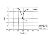
- FIG. 2 is an explanatory diagram showing the return loss characteristics of the dual-polarized transmission / reception antenna 1.
- the characteristics of the dual-polarized transmission / reception antenna 1 described below are as follows.
- the length directions of the side 11 and the side 12 of the ground conductor plate 10 are the Y axis and the X axis, respectively.
- the direction orthogonal to the conductor plate 10 will be described as the Z-axis direction.
- the resonance point is one point A indicated by an arrow, which indicates that the resonance frequencies of the two antennas are equal.
- FIG. 3 is an explanatory diagram showing the directivity characteristics of the dual-polarized transmission / reception antenna 1.
- ⁇ Z As shown in the directivity characteristics of FIGS. 3 (a) and 3 (b), according to the dual polarization transmitting / receiving antenna 1 of the present embodiment, ⁇ Z as shown by the regions B to D surrounded by dotted lines.
- ⁇ Z By having the maximum radiation direction of both horizontal / vertical polarized waves in the direction (direction perpendicular to the ground conductor plate 10), it is possible to simultaneously transmit and receive two polarized waves of vertical polarization and horizontal polarization in the same frequency band. From the directivity characteristics (XY plane) shown in FIG. 3C, it can be said that one polarization has a substantially uniform characteristic.
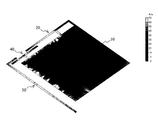
- FIG. 4 is an explanatory diagram showing the distribution state of the surface current density (2.44 GHz) in the ground conductor plate 10 of the dual-polarized transmission / reception antenna 1.
- the surface current density in a specific phase generated in the ground conductor plate 10 is merely that the high-frequency current is applied to the edge (near the outer periphery) of the ground conductor plate 10. This is the same in any phase including other phases not shown. That is, according to the dual-polarized transmission / reception antenna 1 of the present embodiment, the high-frequency current does not get on the central portion of the ground conductor plate 10.
- the ground conductor plate 10 when the length of one side of the ground conductor plate 10 is L, it is possible to cut out the central L / 2 or 3L / 5 square range, or the range of the vicinity thereof. Thereby, it is possible to reduce the weight of both the polarization transmitting / receiving antennas 1. Further, since the high frequency current is not applied to the central region of the ground conductor plate 10, an electronic circuit or the like can be disposed in the region. It is also possible to cut out the central region as described above and arrange an electronic circuit or the like in the cutout region.
- the opposite sides formed at substantially the same resonance frequency so as to face the two orthogonal sides 11 and 12 of the ground conductor plate 10.
- the F antenna 20 and the dipole antenna 30 are disposed so as to be substantially orthogonal.
- the EM power feeding portion 41 of the common power feeding portion 40 is disposed opposite to the open end side of the inverted F antenna 20 and the open end side of the dipole antenna 30, so that electromagnetic power feeding to both antennas 20 and 30 is performed. Is performed at one point.
- the dual polarization transmission / reception antenna 1 of the present embodiment by adopting the one-point feeding method by EM feeding, the feeding section and the high frequency circuit can be simplified, and the vertically polarized wave can be obtained with a simpler configuration.
- a dual-polarized transmission / reception antenna capable of transmitting and receiving horizontal polarization is obtained.
- both polarization transmitting and receiving antennas can be miniaturized, and the center portion of the ground conductor plate can be cut off or an electronic circuit can be provided.
- FIG. 5 is an explanatory diagram showing the arrangement of the polarization transmitting / receiving antennas 1 and the switching of the polarization. Except for FIG. 9A, the drawings in FIG. 5 and the following drawings are simplified because they illustrate the shape and arrangement of each antenna.
- FIG. 5A is the same as the dual-polarized transmission / reception antenna 1 described in FIG. 1, and shows a dual-polarization transmission / reception antenna 1 serving as a reference. Even when the both-polarized transmission / reception antennas 1 in FIG. 5 (a) are arranged symmetrically in FIG. 5 (b) in the left-right symmetry (the front and back are reversed with respect to the longitudinal center axis), FIG.
- FIG. 6 shows a configuration of a modified example of the dual-polarized transmission / reception antenna 1.
- FIG. 6A shows two sets of the dual-polarized transmission / reception antennas 1 described in FIG. 1 arranged in point symmetry (on the opposite side). That is, with respect to one ground conductor plate 10, the first dual-polarized transmission / reception antenna 1 a including the inverted F antenna 20 a, the dipole antenna 30 a, and the feeding unit 40 a, the inverted F antenna 20 b, the dipole antenna 30 b, and the feeding unit 40 b are provided. Two sets of the second polarized wave transmitting / receiving antennas 1b are arranged point-symmetrically.
- the resonance frequency (for example, 2.44 GHz) of both the polarization transmitting / receiving antennas 1a and 1b is made common, thereby gain compared with the both polarization transmitting / receiving antenna 1 described in the embodiment. Can be improved.
- the first dual-polarized transmission / reception antenna 1a and the second dual-polarization transmission / reception antenna 1b as antennas of different frequency bands, a dual-frequency dual-polarization transmission / reception antenna can be provided.
- the first dual-polarized transmission / reception antenna 1a is set to the 2.44 GHz band
- the second dual-polarization transmission / reception antenna 1b is set to the 5.2 GHz band.
- both polarization transmitting / receiving antennas When two sets of both polarization transmitting / receiving antennas are arranged as shown in FIG. 6 (b), the vertically polarized waves and the horizontally polarized waves cancel each other. If two sets are fed at different timings by switching or the like, both polarization transmission / reception becomes possible. Moreover, if the element dimensions of 20a and 30a, 20b and 30b are controlled and the respective resonance frequencies are changed, it is possible to construct an antenna system that realizes dual-polarized transmission / reception for both frequencies.
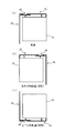
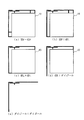
- FIG. 7 shows modified examples in which other types of antennas are combined.
- any one of an inverted F antenna, an inverted L antenna, and a dipole antenna can be selected, and the selectable combinations are shown in FIG.
- the inverted F antenna and the inverted L antenna are simply expressed as inverted F and inverted L
- the dipole antenna is simply expressed as a dipole.
- both ⁇ / 4 type antennas are arranged as the first linear antenna and the second linear antenna.
- FIG. 7A shows an inverted F + inverted F dual-polarized transmission / reception antenna in which two inverted F antennas are arranged so that the open end side is on the same corner side of the ground conductor plate 10.
- the open end side is bent so as to face the EM power feeding portion 41, similarly to the bent portion 32 of the dipole antenna 30 described in FIG. The same applies to the bending of the open end side of one of the antennas so as to face the EM power feeding portion 41 in FIGS. 7B to 7E.
- FIG. 7B is an example of an inverted F + inverted L type dual-polarized transmission / reception antenna in which an inverted L antenna is arranged instead of the dipole antenna 30 of the embodiment. Also in this example, the feeding portion 40 side is bent with the open end side, and a short-circuit portion is provided on the opposite side.
- FIG. 7C shows an inverted L + inverted L type dual-polarized transmission / reception antenna in which both the inverted F antenna 20 and the dipole antenna 30 of the embodiment are replaced with an inverted L antenna. In each of FIGS. 7A to 7C, the short-circuit portions of both antennas are arranged diagonally with respect to the ground conductor plate 10.
- FIG. 7D shows an example of an inverted L + dipole dual-polarized transmission / reception antenna in which an inverted L antenna is arranged instead of the inverted F antenna 20 of the embodiment.
- ⁇ / 4 type and ⁇ / 2 type antennas are used as in the embodiment.
- both the polarization transmitting / receiving antennas use ⁇ / 4 type antennas (inverted F antenna, inverted L antenna).
- the ground conductor plate 10 is required.
- a high-frequency current is also applied to the central portion of the ground conductor plate 10 in each of the modified examples of FIGS. never ride. Therefore, also in these modified examples, the central portion of the ground conductor plate 10 can be cut out or an electronic circuit can be provided.
- FIG. 7E shows an example of a dipole + dipole type dual polarization transmitting / receiving antenna in which a dipole antenna is arranged instead of the inverted F antenna 20 of the embodiment. According to this modification, since both are ⁇ / 2 type antennas, the ground conductor plate 10 is not required, and a light dual-polarized transmission / reception antenna can be obtained.
- both of the first dual-polarized transmission / reception antenna 1a and the second dual-polarization transmission / reception antenna 1b are shown in FIGS. 7 (a) to (e). It is also possible to select any one of them.
- FIG. 8 is an explanatory diagram of a modified example in which the shape of the power feeding portion is changed in both polarization transmitting / receiving antennas.
- the antenna main portion 21 of the inverted F antenna 20 and the bent portion 32 of the dipole antenna 30 are arranged on substantially the same straight line.
- the EM feed portion 41 is disposed opposite to the open ends of both antennas.
- the open end side of the dipole antenna 30c (second linear antenna) is not bent, and only the linear antenna main portion 31c is configured, and the EM power feeding portion 41c is bent instead.
- the dipole antenna 30c is disposed opposite to the open end.
- FIG. 8A the open end side of the dipole antenna 30c (second linear antenna) is not bent, and only the linear antenna main portion 31c is configured, and the EM power feeding portion 41c is bent instead.
- the dipole antenna 30c is disposed opposite to the open end.
- the antenna main portion 21 of the inverted F antenna 20 and the bent portion 32 of the dipole antenna 30d are not arranged on the same line but are arranged in parallel at a predetermined interval, and at the predetermined interval.
- the EM power feeding part 41d is arranged inside. Accordingly, in the example of FIG. 8, when the side facing the ground conductor plate 10 of the EM power feeding portion 41d is the inside and the opposite side is the outside, the antenna main portion 21 of the inverted F antenna 20 is outside the EM feeding portion 41d.
- the bent portion of the dipole antenna 30d faces the inside of the EM power feeding portion 41d.
- positioning of EM electric power feeding part FIG. The same can be applied to each of the modified examples described in FIG. 7 and the modified examples described later.
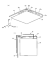
- FIG. 9 is an explanatory diagram showing the configuration of another modified example of the dual-polarized transmission / reception antenna 1.
- FIG. 9A shows a modified example of the dual-polarized transmission / reception antenna in which the inverted F antenna 20, the dipole antenna 30, and the power feeding unit 40 have a three-dimensional structure. As shown in FIG. 9A, the first short circuit portion 22e and the second short circuit portion 23e of the inverted F antenna 20e connected to the ground conductor plate 10 are bent at a right angle with respect to the ground conductor plate 10, thereby 1 on the ZY plane.
- the central portion where the voltage is zero or the vicinity thereof is connected by the short-circuit portion 33e, and the short-circuit portion 33e is bent at a right angle with respect to the ground conductor plate 10, thereby It is formed on a plane.
- the feed line 42e has a three-dimensional structure so as to be orthogonal to the ground conductor plate 10 in the same manner. It is formed on the -Y plane.
- the bent portion 32e of the dipole antenna 30e has a shorter length than the embodiment described with reference to FIG. 1 due to the three-dimensional structure.
- the end portion 43e on the dipole antenna 30e side of the EM feed portion 41e is not 12 (see FIG. 1). According to the modification shown in FIG. 9A, it is possible to reduce the arrangement area of the entire antenna for both polarization transmission and reception.
- a second dual-polarized transmission / reception antenna is reversely arranged on the outer side of the inverted F antenna 20 and the dipole antenna 30 of the dual-polarization transmission / reception antenna 1 described in FIG.
- An L antenna 50 and a dipole antenna 60 are provided.
- the inverted L antenna 50 forms a short-circuit portion (a feeding line portion in a general inverted-L antenna) on an extension line of the second short-circuit portion 23 of the inverted F antenna 20.
- the electric power feeding part 40 it feeds electromagnetically in common with two sets of both polarized-wave transmission / reception antennas. According to this modification, it is possible to provide a multi-frequency dual-polarized transmission / reception antenna.
- the dual-polarized transmission / reception antenna 1 of the present embodiment and the modified examples thereof have been described, but various modifications can be made.
- the single-layer dual-polarized transmission / reception antenna has been described.
- both the embodiment and the modification described above on the high relative dielectric constant substrate such as glass epoxy resin are used.
- the antenna layer may be multilayered (for example, two layers, four layers, eight layers).
- the respective parts of the ground conductor plate 10, the inverted F antenna 20, the dipole antenna 30, and the power feeding unit 40 in the dual-polarized transmission / reception antennas of each layer are connected to each other via.
- the power supply line 42 of the power supply unit 40 may have a single layer and may be connected to the EM power supply unit 41 of any one layer.
- the antenna is made of n layers, and the high relative dielectric constant substrate is made of n ⁇ 1 layers, so that the multi-polarization antenna for both polarization transmission and reception is obtained. You may arrange
- the antenna element shape in a straight state is described except for the open end.
- the shape is not limited to the linear shape.
- a meander shape, a helical shape, or a bent end shape (a bent end shape) can be used.
Abstract
Provided is a dual polarized wave transmission/reception antenna having a simplified configuration. The dual polarized wave transmission/reception antenna uses, among a dipole antenna, an inverted-F antenna, and an inverted-L antenna, any two antennas the resonance frequencies of which are controlled to be substantially equal to each other, and open-end sides of the two antennas are arranged so as to be orthogonal to each other at a prescribed distance. An EM power feeding unit is arranged so as to face each of the open-end sides with a prescribed interval. A power feeding line is electrically connected to the EM power feeding unit. Thus, according to the dual polarized wave transmission/reception antenna of the present embodiment, one-point electromagnetic power feeding is carried out from respective open-end sides of two linear antennas which are orthogonal to each other and the resonance frequencies of which are substantially equal to each other, whereby a power feeding unit and a high-frequency circuit can be simplified, and a vertically polarized wave and a horizontally polarized wave can be transmitted/received with a simpler configuration. As a result of using an inverted-F antenna or an inverted-L antenna, the dual polarized wave transmission/reception antenna can be downsized, and further, the center portion of a ground conductor thereof can be cut off or an electronic circuit can be provided thereto.
Description
本発明は、両偏波送受用アンテナに係り、垂直偏波と水平偏波の送受信を行うアンテナに関する。
The present invention relates to a dual-polarized transmission / reception antenna, and relates to an antenna that transmits and receives vertical polarization and horizontal polarization.
垂直偏波と水平偏波の2偏波を送受信する場合、両偏波に対応する2つの給電点が必要になる。
このような2偏波を送受信する技術として、偏波共用アンテナが提案されている(非特許文献1、2参照)。この偏波共用アンテナは、同一周波数において垂直偏波と水平偏波の2偏波を切り替えて、又は同時に送受信することができ、衛星通信やリモートセンシング等の分野で使用されている。 When transmitting and receiving two polarizations of vertical polarization and horizontal polarization, two feeding points corresponding to both polarizations are required.
As a technique for transmitting and receiving such two polarized waves, a polarization sharing antenna has been proposed (seeNon-Patent Documents 1 and 2). This dual-polarized antenna can transmit and receive two polarizations of vertical polarization and horizontal polarization at the same frequency, or can transmit and receive simultaneously, and is used in fields such as satellite communication and remote sensing.
このような2偏波を送受信する技術として、偏波共用アンテナが提案されている(非特許文献1、2参照)。この偏波共用アンテナは、同一周波数において垂直偏波と水平偏波の2偏波を切り替えて、又は同時に送受信することができ、衛星通信やリモートセンシング等の分野で使用されている。 When transmitting and receiving two polarizations of vertical polarization and horizontal polarization, two feeding points corresponding to both polarizations are required.
As a technique for transmitting and receiving such two polarized waves, a polarization sharing antenna has been proposed (see
しかし、従来の偏波共用アンテナでは、同一平面上に配設した2つの垂直偏波用アンテナと水平偏波用アンテナの個々に給電線を用意する必要があった。
また、2つのアンテナを同時に送受信するためには、垂直偏波アンテナ用の高周波回路と、水平偏波アンテナ用の高周波回路の2つの高周波回路が必要であった。 However, in the conventional dual-polarized antenna, it is necessary to prepare a feeding line for each of two vertically polarized antennas and horizontally polarized antennas arranged on the same plane.
In order to simultaneously transmit and receive two antennas, two high-frequency circuits, ie, a high-frequency circuit for a vertically polarized antenna and a high-frequency circuit for a horizontally polarized antenna are required.
本発明は、より簡単な構成で垂直偏波と水平偏波の送受信を可能にすることを目的とする。
The object of the present invention is to enable transmission and reception of vertically polarized waves and horizontally polarized waves with a simpler configuration.
(1)請求項1に記載の発明では、少なくとも1の開放端を有する第1線状アンテナと、少なくとも1の開放端を有し、当該開放端側と前記第1線状アンテナの開放端側とが所定間隔で、前記第1線状アンテナとほぼ直交状態に配設され、前記第1線状アンテナの共振周波数と実質同一の共振周波数に形成された第2線状アンテナと、前記第1線状アンテナの前記開放端側、及び前記第2線状アンテナの前記開放端側のそれぞれと、所定間隔をおいて対向配置されることで、前記第1線状アンテナ及び前記第2線状アンテナに電磁的に接続される電磁結合型給電部(EM給電部)と、前記EM給電部と電気的に接続され、前記EM給電部を介して前記第1線状アンテナ及び前記第2線状アンテナに給電する給電ラインと、を具備したことを特徴とする両偏波送受用アンテナを提供する。
(2)請求項2に記載の発明では、地導体板を更に備え、前記第1線状アンテナは、前記地導体板の端面とほぼ平行に配設され、開放端側が前記EM給電部と対向配置されるアンテナ主部と、前記アンテナ主部の前記開放端側の反対側端部と前記地導体板とを短絡する第1短絡部と、前記アンテナ主部の前記第1短絡部よりも開放側において、前記アンテナ主部と前記地導体板とを短絡する第2短絡部と、を有する逆Fアンテナである、ことを特徴とする請求項1に記載の両偏波送受用アンテナを提供する。
(3)請求項3に記載の発明では、地導体板を更に備え、前記第1線状アンテナは、前記地導体板の端面とほぼ平行に配設され、開放端側が前記EM給電部と対向配置されるアンテナ主部と、前記アンテナ主部の前記開放端側の反対側端部と前記地導体板とを短絡する第1短絡部と、を有する逆Lアンテナである、ことを特徴とする請求項1に記載の両偏波送受用アンテナを提供する。
(4)請求項4に記載の発明では、前記第1線状アンテナは、ダイポールアンテナである、ことを特徴とする請求項1から請求項3のうちのいずれか1の請求項に記載の両偏波送受用アンテナを提供する。
(5)請求項5に記載の発明では、前記第2線状アンテナは、ダイポールアンテナ、逆Fアンテナ、又は、逆Lアンテナである、ことを特徴とする請求項1から請求項4のうちのいずれか1の請求項に記載の両偏波送受用アンテナを提供する。
(6)請求項6に記載の発明では、前記両偏波送受用アンテナの共振周波数f0がf0=2.44GHzである、ことを特徴とする請求項1から請求項5のうちのいずれか1の請求項に記載の両偏波送受用アンテナを提供する。
(7)請求項7に記載の発明では、高比誘電体基板を備え、前記第1線状アンテナと前記第2線状アンテナは、前記高比誘電体基板上に形成されている、ことを特徴とする請求項1から請求項6のうちのいずれか1の請求項に記載の両偏波送受用アンテナを提供する。
(8)請求項8に記載の発明では、前記第1線状アンテナ、前記第2線状アンテナ、及び前記EM給電部のそれぞれは、互いにビア接続された複数層で形成されている、ことを特徴とする請求項1から請求項7のうちのいずれか1の請求項に記載の両偏波送受用アンテナを提供する。
(9)請求項9に記載の発明では、前記第1線状アンテナ及び前記第2線状アンテナは、アンテナエレメント部分の形状が、直線形状、ミアンダ形状、ヘリカル形状、又は、先端折れ曲げ形状、である、ことを特徴とする請求項1から請求項8のうちのいずれか1の請求項に記載の両偏波送受用アンテナを提供する。 (1) In the first aspect of the present invention, the first linear antenna having at least one open end, and at least one open end, the open end side and the open end side of the first linear antenna. Are arranged at a predetermined interval and substantially orthogonal to the first linear antenna, and are formed at a resonance frequency substantially the same as the resonance frequency of the first linear antenna, and the first linear antenna The first linear antenna and the second linear antenna are arranged to be opposed to each of the open end side of the linear antenna and the open end side of the second linear antenna at a predetermined interval. An electromagnetic coupling type power supply unit (EM power supply unit) that is electromagnetically connected to the EM power supply unit, and the first linear antenna and the second linear antenna that are electrically connected to the EM power supply unit via the EM power supply unit A power supply line for supplying power to Providing both polarizations transmitting and receiving antenna to.
(2) In the invention described in claim 2, further comprising a ground conductor plate, the first linear antenna is disposed substantially parallel to an end surface of the ground conductor plate, and an open end side faces the EM power feeding portion. The antenna main part to be arranged, the first short-circuiting part that short-circuits the opposite end part of the antenna main part on the open end side and the ground conductor plate, and the first mains short-circuiting part of the antenna main part that is open. 2. The dual-polarized transmission / reception antenna according toclaim 1, wherein the antenna is an inverted F antenna having a second short-circuit portion that short-circuits the antenna main portion and the ground conductor plate. .
(3) In the invention described inclaim 3, further comprising a ground conductor plate, the first linear antenna is disposed substantially parallel to an end surface of the ground conductor plate, and an open end side faces the EM power feeding portion. It is an inverted L antenna having an antenna main portion to be disposed, and a first short-circuit portion that short-circuits the opposite end portion of the antenna main portion on the open end side and the ground conductor plate. A dual-polarized transmission / reception antenna according to claim 1 is provided.
(4) In the invention according to claim 4, the first linear antenna is a dipole antenna, and both of the claims according to any one ofclaims 1 to 3 are characterized. A polarized wave transmitting / receiving antenna is provided.
(5) In the invention described inclaim 5, the second linear antenna is a dipole antenna, an inverted F antenna, or an inverted L antenna. A dual-polarized transmission / reception antenna according to any one of the claims is provided.
(6) In the invention described in claim 6, the resonance frequency f0 of both the polarization transmitting and receiving antennas is f0 = 2.44 GHz, and any one ofclaims 1 to 5 A dual-polarized transmission / reception antenna according to claim 1 is provided.
(7) The invention according toclaim 7, further comprising a high relative dielectric substrate, wherein the first linear antenna and the second linear antenna are formed on the high relative dielectric substrate. A dual-polarized transmission / reception antenna according to any one of claims 1 to 6 is provided.
(8) In the invention described in claim 8, each of the first linear antenna, the second linear antenna, and the EM feeder is formed of a plurality of layers connected to each other via. A dual-polarized transmission / reception antenna according to any one ofclaims 1 to 7 is provided.
(9) In the invention according to claim 9, in the first linear antenna and the second linear antenna, the shape of the antenna element portion is a linear shape, a meander shape, a helical shape, or a bent end shape, The dual-polarized transmission / reception antenna according to any one ofclaims 1 to 8 is provided.
(2)請求項2に記載の発明では、地導体板を更に備え、前記第1線状アンテナは、前記地導体板の端面とほぼ平行に配設され、開放端側が前記EM給電部と対向配置されるアンテナ主部と、前記アンテナ主部の前記開放端側の反対側端部と前記地導体板とを短絡する第1短絡部と、前記アンテナ主部の前記第1短絡部よりも開放側において、前記アンテナ主部と前記地導体板とを短絡する第2短絡部と、を有する逆Fアンテナである、ことを特徴とする請求項1に記載の両偏波送受用アンテナを提供する。
(3)請求項3に記載の発明では、地導体板を更に備え、前記第1線状アンテナは、前記地導体板の端面とほぼ平行に配設され、開放端側が前記EM給電部と対向配置されるアンテナ主部と、前記アンテナ主部の前記開放端側の反対側端部と前記地導体板とを短絡する第1短絡部と、を有する逆Lアンテナである、ことを特徴とする請求項1に記載の両偏波送受用アンテナを提供する。
(4)請求項4に記載の発明では、前記第1線状アンテナは、ダイポールアンテナである、ことを特徴とする請求項1から請求項3のうちのいずれか1の請求項に記載の両偏波送受用アンテナを提供する。
(5)請求項5に記載の発明では、前記第2線状アンテナは、ダイポールアンテナ、逆Fアンテナ、又は、逆Lアンテナである、ことを特徴とする請求項1から請求項4のうちのいずれか1の請求項に記載の両偏波送受用アンテナを提供する。
(6)請求項6に記載の発明では、前記両偏波送受用アンテナの共振周波数f0がf0=2.44GHzである、ことを特徴とする請求項1から請求項5のうちのいずれか1の請求項に記載の両偏波送受用アンテナを提供する。
(7)請求項7に記載の発明では、高比誘電体基板を備え、前記第1線状アンテナと前記第2線状アンテナは、前記高比誘電体基板上に形成されている、ことを特徴とする請求項1から請求項6のうちのいずれか1の請求項に記載の両偏波送受用アンテナを提供する。
(8)請求項8に記載の発明では、前記第1線状アンテナ、前記第2線状アンテナ、及び前記EM給電部のそれぞれは、互いにビア接続された複数層で形成されている、ことを特徴とする請求項1から請求項7のうちのいずれか1の請求項に記載の両偏波送受用アンテナを提供する。
(9)請求項9に記載の発明では、前記第1線状アンテナ及び前記第2線状アンテナは、アンテナエレメント部分の形状が、直線形状、ミアンダ形状、ヘリカル形状、又は、先端折れ曲げ形状、である、ことを特徴とする請求項1から請求項8のうちのいずれか1の請求項に記載の両偏波送受用アンテナを提供する。 (1) In the first aspect of the present invention, the first linear antenna having at least one open end, and at least one open end, the open end side and the open end side of the first linear antenna. Are arranged at a predetermined interval and substantially orthogonal to the first linear antenna, and are formed at a resonance frequency substantially the same as the resonance frequency of the first linear antenna, and the first linear antenna The first linear antenna and the second linear antenna are arranged to be opposed to each of the open end side of the linear antenna and the open end side of the second linear antenna at a predetermined interval. An electromagnetic coupling type power supply unit (EM power supply unit) that is electromagnetically connected to the EM power supply unit, and the first linear antenna and the second linear antenna that are electrically connected to the EM power supply unit via the EM power supply unit A power supply line for supplying power to Providing both polarizations transmitting and receiving antenna to.
(2) In the invention described in claim 2, further comprising a ground conductor plate, the first linear antenna is disposed substantially parallel to an end surface of the ground conductor plate, and an open end side faces the EM power feeding portion. The antenna main part to be arranged, the first short-circuiting part that short-circuits the opposite end part of the antenna main part on the open end side and the ground conductor plate, and the first mains short-circuiting part of the antenna main part that is open. 2. The dual-polarized transmission / reception antenna according to
(3) In the invention described in
(4) In the invention according to claim 4, the first linear antenna is a dipole antenna, and both of the claims according to any one of
(5) In the invention described in
(6) In the invention described in claim 6, the resonance frequency f0 of both the polarization transmitting and receiving antennas is f0 = 2.44 GHz, and any one of
(7) The invention according to
(8) In the invention described in claim 8, each of the first linear antenna, the second linear antenna, and the EM feeder is formed of a plurality of layers connected to each other via. A dual-polarized transmission / reception antenna according to any one of
(9) In the invention according to claim 9, in the first linear antenna and the second linear antenna, the shape of the antenna element portion is a linear shape, a meander shape, a helical shape, or a bent end shape, The dual-polarized transmission / reception antenna according to any one of
本発明によれば、共振周波数が実質同一である第1線状アンテナと第2線状アンテナを直交配置し、両線状アンテナの両開放端部と所定間隔をおいて対向配置されるEM給電部による1点給電とすることで、より簡単な構成で垂直偏波と水平偏波の送受信を行うことができる。
According to the present invention, the first linear antenna and the second linear antenna having substantially the same resonance frequency are orthogonally arranged, and are opposed to both open ends of the two linear antennas at a predetermined interval. By using one-point power feeding by the unit, vertical polarization and horizontal polarization can be transmitted and received with a simpler configuration.
以下、本発明の両偏波送受用アンテナにおける好適な実施の形態について、図1から図9を参照して詳細に説明する。
(1)実施形態の概要
本実施形態の両偏波送受用アンテナでは、共振周波数が実質同一に調節された、ダイポールアンテナ、逆Fアンテナ、逆Lアンテナの何れか2つを、第1線状アンテナと第2線状アンテナとを使用し、両線状アンテナの開放端側を所定距離隔てて直交配置する。
そして、第1線状アンテナと第2線状アンテナの両開放端側のそれぞれと、所定間隔をおいてEM給電部を対向配置し、このEM給電部に給電ラインを電気的に接続する。
このように、本実施形態の両偏波送受用アンテナによれば、共振周波数が実質同一である2つの直交する線状アンテナの両開放端側から、電磁的な1点給電を実現することで、給電部と高周波回路を簡略化することができる。すなわち、より簡単な構成で垂直偏波と水平偏波の送受信が可能な両偏波送受用アンテナが得られる。
ここで、アンテナの直交配置は、直交状態に配置することで、この直交状態の配置は、厳密な意味での直角にかぎられず、実用の両偏波送受用アンテナを実現できる程度の角度の幅を含むものとし、例えば、π/2±10度の範囲、好ましくはπ/2±5度の範囲に設定される。 A preferred embodiment of the dual-polarized transmission / reception antenna of the present invention will be described in detail below with reference to FIGS.
(1) Outline of Embodiment In the dual-polarized transmission / reception antenna of this embodiment, any two of a dipole antenna, an inverted F antenna, and an inverted L antenna whose resonance frequencies are adjusted to be substantially the same are used as the first linear shape. An antenna and a second linear antenna are used, and the open end sides of the two linear antennas are orthogonally arranged with a predetermined distance therebetween.
Then, an EM power feeding part is disposed opposite to each of the open ends of the first linear antenna and the second linear antenna at a predetermined interval, and the power feeding line is electrically connected to the EM power feeding part.
As described above, according to the dual-polarized transmission / reception antenna of the present embodiment, by realizing electromagnetic one-point power feeding from both open ends of two orthogonal linear antennas having substantially the same resonance frequency. The power feeding unit and the high frequency circuit can be simplified. That is, it is possible to obtain a dual-polarized wave transmission / reception antenna that can transmit and receive vertical polarization and horizontal polarization with a simpler configuration.
Here, the orthogonal arrangement of the antennas is arranged in an orthogonal state, and the arrangement in the orthogonal state is not limited to a right angle in a strict sense, but an angle width that can realize a practical dual-polarized transmission / reception antenna. For example, it is set in the range of π / 2 ± 10 degrees, preferably in the range of π / 2 ± 5 degrees.
具体的には、矩形形状の地導体板10の直交する2辺の一方の辺側に角側を開放端とする逆Fアンテナ20(第1線状アンテナ)と、他方の辺側にダイポールアンテナ30(第2線状アンテナ)を配設し、両開放端側に給電部40のEM給電部41を対向配置させる。
本実施形態では、共振周波数2.44GHz帯の両偏波送受用アンテナとするために、逆Fアンテナ20とダイポールアンテナ30の共振周波数を実質同一に設定する。
逆Fアンテナ20の開放端側の反対側は、第1短絡部22、第2短絡部23により地導体板10に短絡接続されている。
ダイポールアンテナ30は、地導体板10に短絡接続されることはないが、全長の中央部での電圧がゼロであることから、この中央部で地導体板10に接続することは可能である。
このように、第1線状アンテナと第2線状アンテナの少なくとも一方に逆Fアンテナや逆Lアンテナを用いることで、両偏波送受用アンテナを小型化することができ、また、地導体板の中央部を切り取ったり電子回路を設けることができる。 Specifically, an inverted F antenna 20 (first linear antenna) having an open end on one side of two orthogonal sides of the rectangularground conductor plate 10 and a dipole antenna on the other side. 30 (second linear antenna) is disposed, and the EM power feeding portion 41 of the power feeding portion 40 is disposed opposite to both open ends.
In the present embodiment, the resonant frequencies of the invertedF antenna 20 and the dipole antenna 30 are set to be substantially the same in order to obtain a dual-polarized transmission / reception antenna having a resonance frequency of 2.44 GHz.
The opposite side of the open end side of the invertedF antenna 20 is short-circuited to the ground conductor plate 10 by the first short-circuit portion 22 and the second short-circuit portion 23.
Although thedipole antenna 30 is not short-circuited to the ground conductor plate 10, the voltage at the central portion of the entire length is zero, so that it can be connected to the ground conductor plate 10 at this central portion.
As described above, by using an inverted F antenna or an inverted L antenna for at least one of the first linear antenna and the second linear antenna, both polarization transmitting and receiving antennas can be reduced in size, and the ground conductor plate The center portion of the slab can be cut off or an electronic circuit can be provided.
本実施形態では、共振周波数2.44GHz帯の両偏波送受用アンテナとするために、逆Fアンテナ20とダイポールアンテナ30の共振周波数を実質同一に設定する。
逆Fアンテナ20の開放端側の反対側は、第1短絡部22、第2短絡部23により地導体板10に短絡接続されている。
ダイポールアンテナ30は、地導体板10に短絡接続されることはないが、全長の中央部での電圧がゼロであることから、この中央部で地導体板10に接続することは可能である。
このように、第1線状アンテナと第2線状アンテナの少なくとも一方に逆Fアンテナや逆Lアンテナを用いることで、両偏波送受用アンテナを小型化することができ、また、地導体板の中央部を切り取ったり電子回路を設けることができる。 Specifically, an inverted F antenna 20 (first linear antenna) having an open end on one side of two orthogonal sides of the rectangular
In the present embodiment, the resonant frequencies of the inverted
The opposite side of the open end side of the inverted
Although the
As described above, by using an inverted F antenna or an inverted L antenna for at least one of the first linear antenna and the second linear antenna, both polarization transmitting and receiving antennas can be reduced in size, and the ground conductor plate The center portion of the slab can be cut off or an electronic circuit can be provided.
(2)実施形態の詳細
図1は両偏波送受用アンテナにおける実施形態の構成を表した斜視図である。
図1に示すように両偏波送受用アンテナ1は、地導体板10と、逆Fアンテナ20(λ/4型アンテナ)と、ダイポールアンテナ30(λ/2型アンテナ)と、更に、給電部40を備えている。
逆Fアンテナ20は第1線状アンテナとして機能し、ダイポールアンテナ30は第2線状アンテナとして機能している。
地導体板10は、矩形形状の板金により形成されている。地導体板10のサイズは、40mm×40mmである。 (2) Details of Embodiment FIG. 1 is a perspective view showing the configuration of an embodiment of a dual-polarized transmission / reception antenna.
As shown in FIG. 1, the dual-polarized transmission /reception antenna 1 includes a ground conductor plate 10, an inverted F antenna 20 (λ / 4 type antenna), a dipole antenna 30 (λ / 2 type antenna), and a power feeding unit. 40.
The invertedF antenna 20 functions as a first linear antenna, and the dipole antenna 30 functions as a second linear antenna.
Theground conductor plate 10 is formed of a rectangular sheet metal. The size of the ground conductor plate 10 is 40 mm × 40 mm.
図1は両偏波送受用アンテナにおける実施形態の構成を表した斜視図である。
図1に示すように両偏波送受用アンテナ1は、地導体板10と、逆Fアンテナ20(λ/4型アンテナ)と、ダイポールアンテナ30(λ/2型アンテナ)と、更に、給電部40を備えている。
逆Fアンテナ20は第1線状アンテナとして機能し、ダイポールアンテナ30は第2線状アンテナとして機能している。
地導体板10は、矩形形状の板金により形成されている。地導体板10のサイズは、40mm×40mmである。 (2) Details of Embodiment FIG. 1 is a perspective view showing the configuration of an embodiment of a dual-polarized transmission / reception antenna.
As shown in FIG. 1, the dual-polarized transmission /
The inverted
The
逆Fアンテナ20は、地導体板10の辺11とほぼ平行に配設されたアンテナ主部21と、このアンテナ主部21の端部側と地導体板10とを接続する第1短絡部22と第2短絡部23の2つの短絡部を備えている。第1短絡部22は、アンテナ主部21の端部と地導体板10の端部とを接続し、第2短絡部23は、第1短絡部22よりも開放端側でほぼ平行にアンテナ主部21と地導体板10とを接続している。
逆Fアンテナ20は、全体として線幅1mmに形成され、アンテナ主部21の長さが32mm、第1短絡部22と第2短絡部23の長さが4mm(図面では、アンテナ主部21の幅を加えて5mmと表示)である。このサイズの逆Fアンテナ20のサイズは、単独で使用した場合に2.44GHz帯である。
第1短絡部22に対して、第2短絡部23は9mmの間隔を開けて配設されている。
本実施形態の逆Fアンテナ20は、地導体板10と同一材料により一体形成されているが、別々に形成され両者を接続するようにしてもよく、また別材料で形成するようにしてもよい。 The invertedF antenna 20 includes an antenna main portion 21 disposed substantially parallel to the side 11 of the ground conductor plate 10, and a first short-circuit portion 22 that connects the end portion side of the antenna main portion 21 and the ground conductor plate 10. And the second short-circuit portion 23 are provided. The first short-circuit portion 22 connects the end portion of the antenna main portion 21 and the end portion of the ground conductor plate 10, and the second short-circuit portion 23 is substantially parallel to the antenna main portion on the open end side with respect to the first short-circuit portion 22. The part 21 and the ground conductor plate 10 are connected.
Theinverted F antenna 20 is formed with a line width of 1 mm as a whole, the length of the antenna main portion 21 is 32 mm, and the length of the first short-circuit portion 22 and the second short-circuit portion 23 is 4 mm (in the drawing, the antenna main portion 21 The width is added and displayed as 5 mm). The size of the inverted F antenna 20 of this size is 2.44 GHz band when used alone.
With respect to the first short-circuit portion 22, the second short-circuit portion 23 is disposed with an interval of 9 mm.
Theinverted F antenna 20 of the present embodiment is integrally formed of the same material as the ground conductor plate 10, but may be formed separately and connected to each other, or may be formed of a different material. .
逆Fアンテナ20は、全体として線幅1mmに形成され、アンテナ主部21の長さが32mm、第1短絡部22と第2短絡部23の長さが4mm(図面では、アンテナ主部21の幅を加えて5mmと表示)である。このサイズの逆Fアンテナ20のサイズは、単独で使用した場合に2.44GHz帯である。
第1短絡部22に対して、第2短絡部23は9mmの間隔を開けて配設されている。
本実施形態の逆Fアンテナ20は、地導体板10と同一材料により一体形成されているが、別々に形成され両者を接続するようにしてもよく、また別材料で形成するようにしてもよい。 The inverted
The
With respect to the first short-
The
ダイポールアンテナ30は、地導体板10の辺11と直交する他の一辺12とほぼ平行に配設されたアンテナ主部31と、このアンテナ主部31から、辺11方向に向けて延設された屈曲部32を備えている。なお、屈曲部32は後述の給電部40と対向する開放端側として機能している。
ダイポールアンテナ30は、全体として線幅1mmに形成され、アンテナ主部31の長さが51mmに、屈曲部32の長さが7mmに形成されている。アンテナ主部31と地導体板10の辺12との間隔は5mmである。ダイポールアンテナ30は、全長を58mmとすることで単独で使用した場合に、逆Fアンテナ20と同じ2.44GHz帯である。
屈曲部32の開放端と、逆Fアンテナ20におけるアンテナ主部21の開放端とは、両者が接触しないように所定間隔を開けて配置されており、本実施形態では、7mmの間隔(図示しない)が開けられている。
なお、屈曲部32は、給電部40と対向させるために屈曲しているが、後述のように給電部40側が屈曲している場合には不要であり、その分アンテナ主部31を長く形成する(図8(a)参照)。 Thedipole antenna 30 is provided with an antenna main portion 31 disposed substantially in parallel with the other side 12 orthogonal to the side 11 of the ground conductor plate 10, and extends from the antenna main portion 31 toward the side 11. A bent portion 32 is provided. The bent portion 32 functions as an open end side facing a power supply portion 40 described later.
Thedipole antenna 30 is formed with a line width of 1 mm as a whole, the antenna main part 31 is 51 mm long, and the bent part 32 is 7 mm long. The distance between the antenna main portion 31 and the side 12 of the ground conductor plate 10 is 5 mm. The dipole antenna 30 has the same 2.44 GHz band as the inverted F antenna 20 when used alone with an overall length of 58 mm.
The open end of thebent portion 32 and the open end of the antenna main portion 21 in the inverted F antenna 20 are arranged at a predetermined interval so that they do not come into contact with each other. In this embodiment, an interval of 7 mm (not shown) ) Is opened.
Thebent portion 32 is bent so as to face the power feeding portion 40, but is not necessary when the power feeding portion 40 side is bent as will be described later, and the antenna main portion 31 is formed longer by that amount. (See FIG. 8 (a)).
ダイポールアンテナ30は、全体として線幅1mmに形成され、アンテナ主部31の長さが51mmに、屈曲部32の長さが7mmに形成されている。アンテナ主部31と地導体板10の辺12との間隔は5mmである。ダイポールアンテナ30は、全長を58mmとすることで単独で使用した場合に、逆Fアンテナ20と同じ2.44GHz帯である。
屈曲部32の開放端と、逆Fアンテナ20におけるアンテナ主部21の開放端とは、両者が接触しないように所定間隔を開けて配置されており、本実施形態では、7mmの間隔(図示しない)が開けられている。
なお、屈曲部32は、給電部40と対向させるために屈曲しているが、後述のように給電部40側が屈曲している場合には不要であり、その分アンテナ主部31を長く形成する(図8(a)参照)。 The
The
The open end of the
The
給電部40は、地導体板10の辺11と平行に、逆Fアンテナ20の開放端側とダイポールアンテナ30の開放端側(屈曲部32)と所定間隔を開けて対向配置されたEM給電部41と、このEM給電部41と一端側が電気的に接続される給電ライン42を備えている。給電ライン42の他端側は、地導体板10側に延び、その端部に給電ポイントP1を有している。
給電部40は、全体を通して線幅1mmに形成され、EM給電部41の長さは17mm(図示せず)に形成され、両端側の約5mm(図示せず)の給電領域、または、その近傍の値を有する給電領域が、それぞれ逆Fアンテナ20とダイポールアンテナ30の開放端側と、0.5mmの間隔を開けて対向している。 Thepower feeding unit 40 is disposed in parallel with the side 11 of the ground conductor plate 10 so as to be opposed to the open end side of the inverted F antenna 20 and the open end side (bent portion 32) of the dipole antenna 30 with a predetermined distance therebetween. 41 and a power supply line 42 electrically connected to the EM power supply unit 41 at one end side. The other end side of the feed line 42 extends to the ground conductor plate 10 side, and has a feed point P1 at the end thereof.
Thepower feeding unit 40 is formed to have a line width of 1 mm throughout, and the length of the EM power feeding unit 41 is formed to 17 mm (not shown), and about 5 mm (not shown) on both ends, or in the vicinity thereof. The feed region having the value of 1 is opposed to the open end side of the inverted F antenna 20 and the dipole antenna 30 with an interval of 0.5 mm.
給電部40は、全体を通して線幅1mmに形成され、EM給電部41の長さは17mm(図示せず)に形成され、両端側の約5mm(図示せず)の給電領域、または、その近傍の値を有する給電領域が、それぞれ逆Fアンテナ20とダイポールアンテナ30の開放端側と、0.5mmの間隔を開けて対向している。 The
The
なお、一般の逆Fアンテナは、モノポールアンテナを途中で折り曲げて低姿勢化した逆Lアンテナのインピーダンス整合をとりやすくするために、給電点の外側付近に短絡部を設けたものである。そして、給電点は地導体板に接続されない。
これに対して本実施形態の逆Fアンテナ20では、アンテナ主部21の開放端側に対向配置された給電部40で電磁的に結合(EM結合)すると共に、給電点に対応する第2短絡部23が地導体板10に接続されている。
しかし、本実施形態ではEM給電部41から逆Fアンテナ20に電磁給電(EM給電)されることで、アンテナ主部21を介して第2短絡部23にも電流が流れることで、第2短絡部23が一般の給電点と同様に作用し、全体として通常の逆Fアンテナと同様に機能している。
この点、後述する図7や図9(b)で使用する逆Lアンテナについても同様である。 Note that a general inverted-F antenna has a short-circuited portion near the outside of the feeding point in order to facilitate impedance matching of an inverted-L antenna that is bent in the middle to lower the profile. The feeding point is not connected to the ground conductor plate.
On the other hand, in theinverted F antenna 20 of the present embodiment, electromagnetic coupling (EM coupling) is performed by the power feeding unit 40 disposed opposite to the open end side of the antenna main part 21 and the second short circuit corresponding to the power feeding point. The part 23 is connected to the ground conductor plate 10.
However, in the present embodiment, when the EMpower feeding portion 41 is electromagnetically fed (EM feeding) to the inverted F antenna 20, a current also flows to the second short-circuit portion 23 via the antenna main portion 21, thereby causing the second short-circuit. The part 23 acts in the same manner as a general feeding point and functions as a general inverted F antenna as a whole.
The same applies to the inverted L antenna used in FIGS. 7 and 9B described later.
これに対して本実施形態の逆Fアンテナ20では、アンテナ主部21の開放端側に対向配置された給電部40で電磁的に結合(EM結合)すると共に、給電点に対応する第2短絡部23が地導体板10に接続されている。
しかし、本実施形態ではEM給電部41から逆Fアンテナ20に電磁給電(EM給電)されることで、アンテナ主部21を介して第2短絡部23にも電流が流れることで、第2短絡部23が一般の給電点と同様に作用し、全体として通常の逆Fアンテナと同様に機能している。
この点、後述する図7や図9(b)で使用する逆Lアンテナについても同様である。 Note that a general inverted-F antenna has a short-circuited portion near the outside of the feeding point in order to facilitate impedance matching of an inverted-L antenna that is bent in the middle to lower the profile. The feeding point is not connected to the ground conductor plate.
On the other hand, in the
However, in the present embodiment, when the EM
The same applies to the inverted L antenna used in FIGS. 7 and 9B described later.
以上のように構成された両偏波送受用アンテナについてのシミュレーションを行った結果について説明する。
すなわち、逆Fアンテナ20(λ/4型)と、ダイポールアンテナ30(λ/2型)を板金上に直交に配置し、EM結合による1点給電した結果、地導体板10に垂直な方向(θ=0°,180°)にEθ,Eφ成分の最大利得を確保し、両偏波送受用アンテナ1となっている。また、両偏波送受用アンテナ1は、放射効率=95%強と非常に良好な特性を得ている。 The result of having performed the simulation about the dual polarization transmitting / receiving antenna configured as described above will be described.
In other words, the inverted F antenna 20 (λ / 4 type) and the dipole antenna 30 (λ / 2 type) are arranged orthogonally on the sheet metal and fed at one point by EM coupling. As a result, the direction perpendicular to the ground conductor plate 10 ( The maximum gain of Eθ and Eφ components is ensured at θ = 0 ° and 180 °, and the dual-polarized transmission /reception antenna 1 is obtained. Further, both polarization transmitting / receiving antennas 1 have very good characteristics with radiation efficiency of slightly over 95%.
すなわち、逆Fアンテナ20(λ/4型)と、ダイポールアンテナ30(λ/2型)を板金上に直交に配置し、EM結合による1点給電した結果、地導体板10に垂直な方向(θ=0°,180°)にEθ,Eφ成分の最大利得を確保し、両偏波送受用アンテナ1となっている。また、両偏波送受用アンテナ1は、放射効率=95%強と非常に良好な特性を得ている。 The result of having performed the simulation about the dual polarization transmitting / receiving antenna configured as described above will be described.
In other words, the inverted F antenna 20 (λ / 4 type) and the dipole antenna 30 (λ / 2 type) are arranged orthogonally on the sheet metal and fed at one point by EM coupling. As a result, the direction perpendicular to the ground conductor plate 10 ( The maximum gain of Eθ and Eφ components is ensured at θ = 0 ° and 180 °, and the dual-polarized transmission /
図2は、両偏波送受用アンテナ1のリターンロス特性を表した説明図である。
なお、以下に説明する両偏波送受用アンテナ1の特性については、図1に示したように、地導体板10の辺11と辺12の長さ方向をそれぞれY軸、X軸とし、地導体板10と直交する方向をZ軸方向として説明する。
図2のリターンロス特性図に示されるように、両偏波送受用アンテナ1は、共振点が矢印で示す1点Aであり、2つのアンテナの共振周波数が等しいことを表している。 FIG. 2 is an explanatory diagram showing the return loss characteristics of the dual-polarized transmission /reception antenna 1.
In addition, as shown in FIG. 1, the characteristics of the dual-polarized transmission /reception antenna 1 described below are as follows. The length directions of the side 11 and the side 12 of the ground conductor plate 10 are the Y axis and the X axis, respectively. The direction orthogonal to the conductor plate 10 will be described as the Z-axis direction.
As shown in the return loss characteristic diagram of FIG. 2, in both polarization transmitting / receivingantennas 1, the resonance point is one point A indicated by an arrow, which indicates that the resonance frequencies of the two antennas are equal.
なお、以下に説明する両偏波送受用アンテナ1の特性については、図1に示したように、地導体板10の辺11と辺12の長さ方向をそれぞれY軸、X軸とし、地導体板10と直交する方向をZ軸方向として説明する。
図2のリターンロス特性図に示されるように、両偏波送受用アンテナ1は、共振点が矢印で示す1点Aであり、2つのアンテナの共振周波数が等しいことを表している。 FIG. 2 is an explanatory diagram showing the return loss characteristics of the dual-polarized transmission /
In addition, as shown in FIG. 1, the characteristics of the dual-polarized transmission /
As shown in the return loss characteristic diagram of FIG. 2, in both polarization transmitting / receiving
図3は、両偏波送受用アンテナ1の指向性特性を表した説明図である。
図3は、共振周波数2.44GHzにおける、(a)がZ-X面(φ=0°)の、(b)がZ-Y面(φ=90°)の、(c)がX-Y面(θ=90°)の指向性特性を表している。 FIG. 3 is an explanatory diagram showing the directivity characteristics of the dual-polarized transmission /reception antenna 1.
FIG. 3 shows that at a resonance frequency of 2.44 GHz, (a) is the ZX plane (φ = 0 °), (b) is the ZY plane (φ = 90 °), and (c) is the XY plane. The directivity characteristic of the surface (θ = 90 °) is shown.
図3は、共振周波数2.44GHzにおける、(a)がZ-X面(φ=0°)の、(b)がZ-Y面(φ=90°)の、(c)がX-Y面(θ=90°)の指向性特性を表している。 FIG. 3 is an explanatory diagram showing the directivity characteristics of the dual-polarized transmission /
FIG. 3 shows that at a resonance frequency of 2.44 GHz, (a) is the ZX plane (φ = 0 °), (b) is the ZY plane (φ = 90 °), and (c) is the XY plane. The directivity characteristic of the surface (θ = 90 °) is shown.
図3(a)、(b)の指向性特性に示したように、本実施形態の両偏波送受用アンテナ1によれば、点線で囲った領域B~Dで示されるように、±Z方向(地導体板10に垂直な方向)に水平/垂直両偏波の最大放射方向を持つことで、同一周波数帯における垂直偏波と水平偏波の2偏波を同時に送受信することができる。
図3(c)に示した指向性特性(X-Y平面)からは、1偏波がほぼ一様な特性を有していることがいえる。
また、図3(c)下部に示したように、本実施形態の両偏波送受用アンテナ1では、放射効率=95.4%と高効率が確保されている。 As shown in the directivity characteristics of FIGS. 3 (a) and 3 (b), according to the dual polarization transmitting / receivingantenna 1 of the present embodiment, ± Z as shown by the regions B to D surrounded by dotted lines. By having the maximum radiation direction of both horizontal / vertical polarized waves in the direction (direction perpendicular to the ground conductor plate 10), it is possible to simultaneously transmit and receive two polarized waves of vertical polarization and horizontal polarization in the same frequency band.
From the directivity characteristics (XY plane) shown in FIG. 3C, it can be said that one polarization has a substantially uniform characteristic.
In addition, as shown in the lower part of FIG. 3 (c), the dual-polarized transmission /reception antenna 1 of the present embodiment ensures high efficiency of radiation efficiency = 95.4%.
図3(c)に示した指向性特性(X-Y平面)からは、1偏波がほぼ一様な特性を有していることがいえる。
また、図3(c)下部に示したように、本実施形態の両偏波送受用アンテナ1では、放射効率=95.4%と高効率が確保されている。 As shown in the directivity characteristics of FIGS. 3 (a) and 3 (b), according to the dual polarization transmitting / receiving
From the directivity characteristics (XY plane) shown in FIG. 3C, it can be said that one polarization has a substantially uniform characteristic.
In addition, as shown in the lower part of FIG. 3 (c), the dual-polarized transmission /
図4は、両偏波送受用アンテナ1の地導体板10における面電流密度(2.44GHz)の分布状態を表した説明図である。
図4に示されるように、地導体板10に発生している、或る特定位相における面電流密度は、地導体板10のエッジ(外周辺近傍)に高周波電流が乗るだけである。これは、図示していない他の位相を含めたいずれの位相においても同様である。
即ち、本実施形態の両偏波送受用アンテナ1によれば、地導体板10の中央部分に高周波電流が乗ることはない。
従って、地導体板10の一辺の長さをLとした場合、中央のL/2若しくは3L/5四方の範囲、又はその近傍領域の範囲を切り取ることが可能である。これにより、両偏波送受用アンテナ1の重量を軽くすることが可能である。
また、地導体板10の当該中央領域に高周波電流が乗らないことから、当該領域内に電子回路等を配設することも可能である。上述のように中央領域を切り取って、切り取り領域内に電子回路等を配設することも可能である。 FIG. 4 is an explanatory diagram showing the distribution state of the surface current density (2.44 GHz) in theground conductor plate 10 of the dual-polarized transmission / reception antenna 1.
As shown in FIG. 4, the surface current density in a specific phase generated in theground conductor plate 10 is merely that the high-frequency current is applied to the edge (near the outer periphery) of the ground conductor plate 10. This is the same in any phase including other phases not shown.
That is, according to the dual-polarized transmission /reception antenna 1 of the present embodiment, the high-frequency current does not get on the central portion of the ground conductor plate 10.
Therefore, when the length of one side of theground conductor plate 10 is L, it is possible to cut out the central L / 2 or 3L / 5 square range, or the range of the vicinity thereof. Thereby, it is possible to reduce the weight of both the polarization transmitting / receiving antennas 1.
Further, since the high frequency current is not applied to the central region of theground conductor plate 10, an electronic circuit or the like can be disposed in the region. It is also possible to cut out the central region as described above and arrange an electronic circuit or the like in the cutout region.
図4に示されるように、地導体板10に発生している、或る特定位相における面電流密度は、地導体板10のエッジ(外周辺近傍)に高周波電流が乗るだけである。これは、図示していない他の位相を含めたいずれの位相においても同様である。
即ち、本実施形態の両偏波送受用アンテナ1によれば、地導体板10の中央部分に高周波電流が乗ることはない。
従って、地導体板10の一辺の長さをLとした場合、中央のL/2若しくは3L/5四方の範囲、又はその近傍領域の範囲を切り取ることが可能である。これにより、両偏波送受用アンテナ1の重量を軽くすることが可能である。
また、地導体板10の当該中央領域に高周波電流が乗らないことから、当該領域内に電子回路等を配設することも可能である。上述のように中央領域を切り取って、切り取り領域内に電子回路等を配設することも可能である。 FIG. 4 is an explanatory diagram showing the distribution state of the surface current density (2.44 GHz) in the
As shown in FIG. 4, the surface current density in a specific phase generated in the
That is, according to the dual-polarized transmission /
Therefore, when the length of one side of the
Further, since the high frequency current is not applied to the central region of the
以上説明したように、本実施形態の両偏波送受用アンテナ1によれば、地導体板10の直交する2辺11、12のそれぞれに対向させて、実質同一の共振周波数に形成された逆Fアンテナ20とダイポールアンテナ30を実質直交するように配設する。
そして、逆Fアンテナ20の開放端側とダイポールアンテナ30の開放端側のそれぞれに共通の給電部40のEM給電部41を対向配置することで、両アンテナ20、30に対して電磁的な給電を1点で行う。
このように本実施形態の両偏波送受用アンテナ1では、EM給電による1点給電方式を採用することで、給電部と高周波回路を簡略化することができ、より簡単な構成で垂直偏波と水平偏波の送受信が可能な両偏波送受用アンテナが得られる。
また、第1線状アンテナとして逆Fアンテナを使用することで、両偏波送受用アンテナを小型化することができ、また、地導体板の中央部を切り取ったり電子回路を設けることができる。 As described above, according to the dual-polarized transmission /reception antenna 1 of the present embodiment, the opposite sides formed at substantially the same resonance frequency so as to face the two orthogonal sides 11 and 12 of the ground conductor plate 10. The F antenna 20 and the dipole antenna 30 are disposed so as to be substantially orthogonal.
Then, the EMpower feeding portion 41 of the common power feeding portion 40 is disposed opposite to the open end side of the inverted F antenna 20 and the open end side of the dipole antenna 30, so that electromagnetic power feeding to both antennas 20 and 30 is performed. Is performed at one point.
As described above, in the dual polarization transmission /reception antenna 1 of the present embodiment, by adopting the one-point feeding method by EM feeding, the feeding section and the high frequency circuit can be simplified, and the vertically polarized wave can be obtained with a simpler configuration. Thus, a dual-polarized transmission / reception antenna capable of transmitting and receiving horizontal polarization is obtained.
In addition, by using an inverted F antenna as the first linear antenna, both polarization transmitting and receiving antennas can be miniaturized, and the center portion of the ground conductor plate can be cut off or an electronic circuit can be provided.
そして、逆Fアンテナ20の開放端側とダイポールアンテナ30の開放端側のそれぞれに共通の給電部40のEM給電部41を対向配置することで、両アンテナ20、30に対して電磁的な給電を1点で行う。
このように本実施形態の両偏波送受用アンテナ1では、EM給電による1点給電方式を採用することで、給電部と高周波回路を簡略化することができ、より簡単な構成で垂直偏波と水平偏波の送受信が可能な両偏波送受用アンテナが得られる。
また、第1線状アンテナとして逆Fアンテナを使用することで、両偏波送受用アンテナを小型化することができ、また、地導体板の中央部を切り取ったり電子回路を設けることができる。 As described above, according to the dual-polarized transmission /
Then, the EM
As described above, in the dual polarization transmission /
In addition, by using an inverted F antenna as the first linear antenna, both polarization transmitting and receiving antennas can be miniaturized, and the center portion of the ground conductor plate can be cut off or an electronic circuit can be provided.
図5は、両偏波送受用アンテナ1の配置と偏波の入れ替えについて表した説明図である。
なお、図9(a)を除き、図5以下の図面では、各アンテナの形状や配置状態を説明するものなので、簡略化して表している。
図5(a)は、図1で説明した両偏波送受用アンテナ1と同じで、基準となる両偏波送受用アンテナ1を表している。
この図5(a)の基準配置した両偏波送受用アンテナ1に対して、図5(b)の左右対称に配置(縦中心軸線に対して裏表を反転)した場合でも、図5(c)の上下対称に配置(横中心軸線に対して裏表を反転)した場合でも、同様に両偏波送受用アンテナとして動作する。すなわち、地導体板10に対するいずれの向きで配置したとしても、配置に対してZ軸方向の両偏波送受用アンテナとして使用することができる。 FIG. 5 is an explanatory diagram showing the arrangement of the polarization transmitting / receivingantennas 1 and the switching of the polarization.
Except for FIG. 9A, the drawings in FIG. 5 and the following drawings are simplified because they illustrate the shape and arrangement of each antenna.
FIG. 5A is the same as the dual-polarized transmission /reception antenna 1 described in FIG. 1, and shows a dual-polarization transmission / reception antenna 1 serving as a reference.
Even when the both-polarized transmission /reception antennas 1 in FIG. 5 (a) are arranged symmetrically in FIG. 5 (b) in the left-right symmetry (the front and back are reversed with respect to the longitudinal center axis), FIG. ) Are arranged symmetrically (inverted with respect to the horizontal central axis), and operate similarly as both polarized wave transmitting / receiving antennas. That is, even if it arrange | positions with which direction with respect to the ground conductor board 10, it can be used as a dual polarized-wave transmission / reception antenna of a Z-axis direction with respect to arrangement | positioning.
なお、図9(a)を除き、図5以下の図面では、各アンテナの形状や配置状態を説明するものなので、簡略化して表している。
図5(a)は、図1で説明した両偏波送受用アンテナ1と同じで、基準となる両偏波送受用アンテナ1を表している。
この図5(a)の基準配置した両偏波送受用アンテナ1に対して、図5(b)の左右対称に配置(縦中心軸線に対して裏表を反転)した場合でも、図5(c)の上下対称に配置(横中心軸線に対して裏表を反転)した場合でも、同様に両偏波送受用アンテナとして動作する。すなわち、地導体板10に対するいずれの向きで配置したとしても、配置に対してZ軸方向の両偏波送受用アンテナとして使用することができる。 FIG. 5 is an explanatory diagram showing the arrangement of the polarization transmitting / receiving
Except for FIG. 9A, the drawings in FIG. 5 and the following drawings are simplified because they illustrate the shape and arrangement of each antenna.
FIG. 5A is the same as the dual-polarized transmission /
Even when the both-polarized transmission /
次に、両偏波送受用アンテナ1における変形例について説明する。
図6は、両偏波送受用アンテナ1の変形例の構成を表したものである。
図6(a)は、図1で説明した両偏波送受用アンテナ1の2組みを、点対称(反対側)に配置したものである。
すなわち、1つの地導体板10に対し、逆Fアンテナ20aとダイポールアンテナ30aと給電部40aからなる第1両偏波送受用アンテナ1aと、逆Fアンテナ20bとダイポールアンテナ30bと給電部40bからなる第2両偏波送受用アンテナ1bの2組を点対称に配置したものである。
この変形例によれば、両両偏波送受用アンテナ1a、1bの共振周波数(例えば、2.44GHz)を共通にすることで、実施形態で説明した両偏波送受用アンテナ1に比べて利得を向上させることができる。
一方、第1両偏波送受用アンテナ1aと第2両偏波送受用アンテナ1bを、それぞれ異なる周波数帯のアンテナとすることで、2周波対応の両偏波送受用アンテナを提供することができる。例えば、第1両偏波送受用アンテナ1aを2.44GHz帯とし、第2両偏波送受用アンテナ1bを5.2GHz帯とする。 Next, a modified example of the dual polarization transmitting / receivingantenna 1 will be described.
FIG. 6 shows a configuration of a modified example of the dual-polarized transmission /reception antenna 1.
FIG. 6A shows two sets of the dual-polarized transmission /reception antennas 1 described in FIG. 1 arranged in point symmetry (on the opposite side).
That is, with respect to oneground conductor plate 10, the first dual-polarized transmission / reception antenna 1 a including the inverted F antenna 20 a, the dipole antenna 30 a, and the feeding unit 40 a, the inverted F antenna 20 b, the dipole antenna 30 b, and the feeding unit 40 b are provided. Two sets of the second polarized wave transmitting / receiving antennas 1b are arranged point-symmetrically.
According to this modification, the resonance frequency (for example, 2.44 GHz) of both the polarization transmitting / receivingantennas 1a and 1b is made common, thereby gain compared with the both polarization transmitting / receiving antenna 1 described in the embodiment. Can be improved.
On the other hand, by using the first dual-polarized transmission / reception antenna 1a and the second dual-polarization transmission /reception antenna 1b as antennas of different frequency bands, a dual-frequency dual-polarization transmission / reception antenna can be provided. . For example, the first dual-polarized transmission / reception antenna 1a is set to the 2.44 GHz band, and the second dual-polarization transmission / reception antenna 1b is set to the 5.2 GHz band.
図6は、両偏波送受用アンテナ1の変形例の構成を表したものである。
図6(a)は、図1で説明した両偏波送受用アンテナ1の2組みを、点対称(反対側)に配置したものである。
すなわち、1つの地導体板10に対し、逆Fアンテナ20aとダイポールアンテナ30aと給電部40aからなる第1両偏波送受用アンテナ1aと、逆Fアンテナ20bとダイポールアンテナ30bと給電部40bからなる第2両偏波送受用アンテナ1bの2組を点対称に配置したものである。
この変形例によれば、両両偏波送受用アンテナ1a、1bの共振周波数(例えば、2.44GHz)を共通にすることで、実施形態で説明した両偏波送受用アンテナ1に比べて利得を向上させることができる。
一方、第1両偏波送受用アンテナ1aと第2両偏波送受用アンテナ1bを、それぞれ異なる周波数帯のアンテナとすることで、2周波対応の両偏波送受用アンテナを提供することができる。例えば、第1両偏波送受用アンテナ1aを2.44GHz帯とし、第2両偏波送受用アンテナ1bを5.2GHz帯とする。 Next, a modified example of the dual polarization transmitting / receiving
FIG. 6 shows a configuration of a modified example of the dual-polarized transmission /
FIG. 6A shows two sets of the dual-polarized transmission /
That is, with respect to one
According to this modification, the resonance frequency (for example, 2.44 GHz) of both the polarization transmitting / receiving
On the other hand, by using the first dual-polarized transmission / reception antenna 1a and the second dual-polarization transmission /
なお、2組の両偏波送受用アンテナを図6(b)に示したように配置した場合、垂直偏波同士、水平偏波同士が相殺してしまうため、採用できない配置であるが、2つの組をスイッチングなどで異なるタイミングで給電を行えば、両偏波送受信が可能となる。また、20aと30a、20bと30bの素子寸法を制御し、各々の共振周波数を変えれば、2周波共用で両偏波送受信を実現するアンテナ系の構築が可能となる。
When two sets of both polarization transmitting / receiving antennas are arranged as shown in FIG. 6 (b), the vertically polarized waves and the horizontally polarized waves cancel each other. If two sets are fed at different timings by switching or the like, both polarization transmission / reception becomes possible. Moreover, if the element dimensions of 20a and 30a, 20b and 30b are controlled and the respective resonance frequencies are changed, it is possible to construct an antenna system that realizes dual-polarized transmission / reception for both frequencies.
図7は、他種類のアンテナを組み合わせた各変形例を表したものである。
第1線状アンテナと第2線状アンテナとしては、それぞれ逆Fアンテナ、逆Lアンテナ、ダイポールアンテナの何れかを選択することが可能であり、その選択可能な組み合わせを図7で表している。なお図面では、逆Fアンテナと逆Lアンテナを簡略して逆F、逆Lと表記し、ダイポールアンテナをダイポールと簡略して表記している。
図7(a)~(c)は、第1の線状アンテナ、第2の線状アンテナとして共にλ/4型のアンテナを配置したものである。
図7(a)は、開放端側が地導体板10の同一の角側に来るように、2つの逆Fアンテナを配置した、逆F+逆F型の両偏波送受用アンテナである。
一方の逆Fアンテナについては、図1で説明したダイポールアンテナ30の屈曲部32と同様に、EM給電部41と対向するように開放端側を屈曲形成している。このEM給電部41に対向させるために一方のアンテナの開放端側を屈曲形成することについては図7(b)~(e)も同様である。 FIG. 7 shows modified examples in which other types of antennas are combined.
As the first linear antenna and the second linear antenna, any one of an inverted F antenna, an inverted L antenna, and a dipole antenna can be selected, and the selectable combinations are shown in FIG. In the drawings, the inverted F antenna and the inverted L antenna are simply expressed as inverted F and inverted L, and the dipole antenna is simply expressed as a dipole.
In FIGS. 7A to 7C, both λ / 4 type antennas are arranged as the first linear antenna and the second linear antenna.
FIG. 7A shows an inverted F + inverted F dual-polarized transmission / reception antenna in which two inverted F antennas are arranged so that the open end side is on the same corner side of theground conductor plate 10.
As for the inverted F antenna, the open end side is bent so as to face the EMpower feeding portion 41, similarly to the bent portion 32 of the dipole antenna 30 described in FIG. The same applies to the bending of the open end side of one of the antennas so as to face the EM power feeding portion 41 in FIGS. 7B to 7E.
第1線状アンテナと第2線状アンテナとしては、それぞれ逆Fアンテナ、逆Lアンテナ、ダイポールアンテナの何れかを選択することが可能であり、その選択可能な組み合わせを図7で表している。なお図面では、逆Fアンテナと逆Lアンテナを簡略して逆F、逆Lと表記し、ダイポールアンテナをダイポールと簡略して表記している。
図7(a)~(c)は、第1の線状アンテナ、第2の線状アンテナとして共にλ/4型のアンテナを配置したものである。
図7(a)は、開放端側が地導体板10の同一の角側に来るように、2つの逆Fアンテナを配置した、逆F+逆F型の両偏波送受用アンテナである。
一方の逆Fアンテナについては、図1で説明したダイポールアンテナ30の屈曲部32と同様に、EM給電部41と対向するように開放端側を屈曲形成している。このEM給電部41に対向させるために一方のアンテナの開放端側を屈曲形成することについては図7(b)~(e)も同様である。 FIG. 7 shows modified examples in which other types of antennas are combined.
As the first linear antenna and the second linear antenna, any one of an inverted F antenna, an inverted L antenna, and a dipole antenna can be selected, and the selectable combinations are shown in FIG. In the drawings, the inverted F antenna and the inverted L antenna are simply expressed as inverted F and inverted L, and the dipole antenna is simply expressed as a dipole.
In FIGS. 7A to 7C, both λ / 4 type antennas are arranged as the first linear antenna and the second linear antenna.
FIG. 7A shows an inverted F + inverted F dual-polarized transmission / reception antenna in which two inverted F antennas are arranged so that the open end side is on the same corner side of the
As for the inverted F antenna, the open end side is bent so as to face the EM
図7(b)は、実施形態のダイポールアンテナ30に変えて逆Lアンテナを配置した、逆F+逆L型の両偏波送受用アンテナの例である。この例においても、給電部40側を開放端側として屈曲形成し、反対側に短絡部を設けている。
図7(c)は、実施形態の逆Fアンテナ20と、ダイポールアンテナ30の両者を、共に逆Lアンテナに変えて配置した、逆L+逆L型の両偏波送受用アンテナである。
図7(a)~(c)共に、両アンテナの短絡部のそれぞれが、地導体板10に対して対角線上に位置するように配置されている。 FIG. 7B is an example of an inverted F + inverted L type dual-polarized transmission / reception antenna in which an inverted L antenna is arranged instead of thedipole antenna 30 of the embodiment. Also in this example, the feeding portion 40 side is bent with the open end side, and a short-circuit portion is provided on the opposite side.
FIG. 7C shows an inverted L + inverted L type dual-polarized transmission / reception antenna in which both theinverted F antenna 20 and the dipole antenna 30 of the embodiment are replaced with an inverted L antenna.
In each of FIGS. 7A to 7C, the short-circuit portions of both antennas are arranged diagonally with respect to theground conductor plate 10.
図7(c)は、実施形態の逆Fアンテナ20と、ダイポールアンテナ30の両者を、共に逆Lアンテナに変えて配置した、逆L+逆L型の両偏波送受用アンテナである。
図7(a)~(c)共に、両アンテナの短絡部のそれぞれが、地導体板10に対して対角線上に位置するように配置されている。 FIG. 7B is an example of an inverted F + inverted L type dual-polarized transmission / reception antenna in which an inverted L antenna is arranged instead of the
FIG. 7C shows an inverted L + inverted L type dual-polarized transmission / reception antenna in which both the
In each of FIGS. 7A to 7C, the short-circuit portions of both antennas are arranged diagonally with respect to the
図7(d)は、実施形態の逆Fアンテナ20に変えて逆Lアンテナを配置した、逆L+ダイポール型の両偏波送受用アンテナの例である。この変形例では、実施形態と同様にλ/4型とλ/2型のアンテナ使用している。
FIG. 7D shows an example of an inverted L + dipole dual-polarized transmission / reception antenna in which an inverted L antenna is arranged instead of the inverted F antenna 20 of the embodiment. In this modification, λ / 4 type and λ / 2 type antennas are used as in the embodiment.
なお、図7(a)~(d)で説明した各変形例にかかる両偏波送受用アンテナでは、いずれもλ/4型のアンテナ(逆Fアンテナ、逆Lアンテナ)を使用しているため、地導体板10が必要になる。
そして、実施形態の両偏波送受用アンテナ1に対して図4で説明したと同様に、図7(a)~(d)の各変形例における地導体板10の中央部にも高周波電流が乗ることはない。従って、これらの変形例においても、地導体板10の中央部を切り取ったり、電子回路を配設したりすることができる。 Note that both the polarization transmitting / receiving antennas according to the modifications described in FIGS. 7A to 7D use λ / 4 type antennas (inverted F antenna, inverted L antenna). Theground conductor plate 10 is required.
In the same manner as described with reference to FIG. 4 for the dual-polarized transmission /reception antenna 1 of the embodiment, a high-frequency current is also applied to the central portion of the ground conductor plate 10 in each of the modified examples of FIGS. Never ride. Therefore, also in these modified examples, the central portion of the ground conductor plate 10 can be cut out or an electronic circuit can be provided.
そして、実施形態の両偏波送受用アンテナ1に対して図4で説明したと同様に、図7(a)~(d)の各変形例における地導体板10の中央部にも高周波電流が乗ることはない。従って、これらの変形例においても、地導体板10の中央部を切り取ったり、電子回路を配設したりすることができる。 Note that both the polarization transmitting / receiving antennas according to the modifications described in FIGS. 7A to 7D use λ / 4 type antennas (inverted F antenna, inverted L antenna). The
In the same manner as described with reference to FIG. 4 for the dual-polarized transmission /
図7(e)は、実施形態の逆Fアンテナ20に変えて、ダイポールアンテナを配置した、ダイポール+ダイポール型の両偏波送受用アンテナの例である。
この変形例によれば、共にλ/2型のアンテナであるため、地導体板10が不要になり、軽量の両偏波送受用アンテナとすることが可能である。 FIG. 7E shows an example of a dipole + dipole type dual polarization transmitting / receiving antenna in which a dipole antenna is arranged instead of theinverted F antenna 20 of the embodiment.
According to this modification, since both are λ / 2 type antennas, theground conductor plate 10 is not required, and a light dual-polarized transmission / reception antenna can be obtained.
この変形例によれば、共にλ/2型のアンテナであるため、地導体板10が不要になり、軽量の両偏波送受用アンテナとすることが可能である。 FIG. 7E shows an example of a dipole + dipole type dual polarization transmitting / receiving antenna in which a dipole antenna is arranged instead of the
According to this modification, since both are λ / 2 type antennas, the
以上、図7(a)~(e)に示した各変形例の両偏波送受用アンテナについて説明したが、その配置を図5で説明したように任意の配置を選択することができる。
また、図6とその変形(多周波)で説明したように、第1両偏波送受用アンテナ1a、第2両偏波送受用アンテナ1bの、いずれも図7(a)~(e)のうちの任意の1つを選択することも可能である。 As described above, the dual-polarized transmission / reception antennas of the modified examples shown in FIGS. 7A to 7E have been described. However, as described with reference to FIG. 5, any arrangement can be selected.
Further, as described in FIG. 6 and its modification (multi-frequency), both of the first dual-polarized transmission / reception antenna 1a and the second dual-polarization transmission /reception antenna 1b are shown in FIGS. 7 (a) to (e). It is also possible to select any one of them.
また、図6とその変形(多周波)で説明したように、第1両偏波送受用アンテナ1a、第2両偏波送受用アンテナ1bの、いずれも図7(a)~(e)のうちの任意の1つを選択することも可能である。 As described above, the dual-polarized transmission / reception antennas of the modified examples shown in FIGS. 7A to 7E have been described. However, as described with reference to FIG. 5, any arrangement can be selected.
Further, as described in FIG. 6 and its modification (multi-frequency), both of the first dual-polarized transmission / reception antenna 1a and the second dual-polarization transmission /
図8は、両偏波送受用アンテナにおける、給電部分の形状を変更した変形例についての説明図である。
図1で説明した実施形態の両偏波送受用アンテナ1では、逆Fアンテナ20のアンテナ主部21と、ダイポールアンテナ30の屈曲部32とが、ほぼ同一直線上に配置されることで、直線状のEM給電部41を両アンテナの開放端側に対向配置する場合について説明した。
図8(a)では、ダイポールアンテナ30c(第2線状アンテナ)の開放端側を屈曲せずに、直線形状のアンテナ主部31cだけで構成し、その代わりにEM給電部41cを屈曲させることで、ダイポールアンテナ30cの開放端に対向配置したものである。
図8(b)では、逆Fアンテナ20のアンテナ主部21と、ダイポールアンテナ30dの屈曲部32とを同一線上に配置せずに、所定間隔を開けて平行に配置すると共に、当該所定間隔の内にEM給電部41dを配置したものである。これにより、図8の例では、EM給電部41dの地導体板10と対向する側を内側、反対側を外側とした場合に、逆Fアンテナ20のアンテナ主部21はEM給電部41dの外側と対向し、ダイポールアンテナ30dの屈曲部はEM給電部41dの内側と対向することになる。
なお、図8(a)、(b)に示した、両アンテナ(第1線状アンテナと第2線状アンテナ)の開放端側の形状及びEM給電部の形状と配置については、図6、図7で説明した各変形例、及び、この後に説明する変形例についても同様に適用が可能である。 FIG. 8 is an explanatory diagram of a modified example in which the shape of the power feeding portion is changed in both polarization transmitting / receiving antennas.
In the dual-polarized transmission /reception antenna 1 of the embodiment described with reference to FIG. 1, the antenna main portion 21 of the inverted F antenna 20 and the bent portion 32 of the dipole antenna 30 are arranged on substantially the same straight line. A case has been described in which the EM feed portion 41 is disposed opposite to the open ends of both antennas.
In FIG. 8A, the open end side of thedipole antenna 30c (second linear antenna) is not bent, and only the linear antenna main portion 31c is configured, and the EM power feeding portion 41c is bent instead. Thus, the dipole antenna 30c is disposed opposite to the open end.
In FIG. 8B, the antennamain portion 21 of the inverted F antenna 20 and the bent portion 32 of the dipole antenna 30d are not arranged on the same line but are arranged in parallel at a predetermined interval, and at the predetermined interval. The EM power feeding part 41d is arranged inside. Accordingly, in the example of FIG. 8, when the side facing the ground conductor plate 10 of the EM power feeding portion 41d is the inside and the opposite side is the outside, the antenna main portion 21 of the inverted F antenna 20 is outside the EM feeding portion 41d. The bent portion of the dipole antenna 30d faces the inside of the EM power feeding portion 41d.
In addition, about the shape of the open end side of both antennas (a 1st linear antenna and a 2nd linear antenna) shown in FIG. 8 (a), (b), and the shape and arrangement | positioning of EM electric power feeding part, FIG. The same can be applied to each of the modified examples described in FIG. 7 and the modified examples described later.
図1で説明した実施形態の両偏波送受用アンテナ1では、逆Fアンテナ20のアンテナ主部21と、ダイポールアンテナ30の屈曲部32とが、ほぼ同一直線上に配置されることで、直線状のEM給電部41を両アンテナの開放端側に対向配置する場合について説明した。
図8(a)では、ダイポールアンテナ30c(第2線状アンテナ)の開放端側を屈曲せずに、直線形状のアンテナ主部31cだけで構成し、その代わりにEM給電部41cを屈曲させることで、ダイポールアンテナ30cの開放端に対向配置したものである。
図8(b)では、逆Fアンテナ20のアンテナ主部21と、ダイポールアンテナ30dの屈曲部32とを同一線上に配置せずに、所定間隔を開けて平行に配置すると共に、当該所定間隔の内にEM給電部41dを配置したものである。これにより、図8の例では、EM給電部41dの地導体板10と対向する側を内側、反対側を外側とした場合に、逆Fアンテナ20のアンテナ主部21はEM給電部41dの外側と対向し、ダイポールアンテナ30dの屈曲部はEM給電部41dの内側と対向することになる。
なお、図8(a)、(b)に示した、両アンテナ(第1線状アンテナと第2線状アンテナ)の開放端側の形状及びEM給電部の形状と配置については、図6、図7で説明した各変形例、及び、この後に説明する変形例についても同様に適用が可能である。 FIG. 8 is an explanatory diagram of a modified example in which the shape of the power feeding portion is changed in both polarization transmitting / receiving antennas.
In the dual-polarized transmission /
In FIG. 8A, the open end side of the
In FIG. 8B, the antenna
In addition, about the shape of the open end side of both antennas (a 1st linear antenna and a 2nd linear antenna) shown in FIG. 8 (a), (b), and the shape and arrangement | positioning of EM electric power feeding part, FIG. The same can be applied to each of the modified examples described in FIG. 7 and the modified examples described later.
図9は、両偏波送受用アンテナ1の他の変形例の構成を表した説明図である。
図9(a)は、逆Fアンテナ20、ダイポールアンテナ30、給電部40を立体構造にした両偏波送受用アンテナの変形例である。
図9(a)に示すように、地導体板10と接続されている逆Fアンテナ20eの第1短絡部22eと第2短絡部23eを地導体板10に対して直角に折り曲げることで、図1におけるZ-Y平面上に形成している。
ダイポールアンテナ30eについては、上述したように電圧がゼロである中央部又はその近傍領域を短絡部33eで接続し、当該短絡部33eを地導体板10に対して直角に折り曲げることで、Z-X平面上に形成している。
また、逆Fアンテナ20eとダイポールアンテナ30eを直角方向に折り曲げたことに対応して、給電部40eについても同様に、地導体板10に対して直交するように給電ライン42eを立体構造とし、Z-Y平面上に形成している。
なお、ダイポールアンテナ30eの屈曲部32eについては、立体構造にしたことに伴い、図1で説明した実施形態に比べて長さが短くなっている。この屈曲部32eを短くしたことに対応して、ダイポールアンテナ30eのEM給電部41eとの対向する長さが短くならないようにするため、EM給電部41eのダイポールアンテナ30e側の端部43eを辺12(図1参照)方向に屈曲させている。
この図9(a)に示した変形例によれば、両偏波送受用アンテナ全体の配設面積を小さくすることができる。 FIG. 9 is an explanatory diagram showing the configuration of another modified example of the dual-polarized transmission /reception antenna 1.
FIG. 9A shows a modified example of the dual-polarized transmission / reception antenna in which theinverted F antenna 20, the dipole antenna 30, and the power feeding unit 40 have a three-dimensional structure.
As shown in FIG. 9A, the firstshort circuit portion 22e and the second short circuit portion 23e of the inverted F antenna 20e connected to the ground conductor plate 10 are bent at a right angle with respect to the ground conductor plate 10, thereby 1 on the ZY plane.
With respect to thedipole antenna 30e, as described above, the central portion where the voltage is zero or the vicinity thereof is connected by the short-circuit portion 33e, and the short-circuit portion 33e is bent at a right angle with respect to the ground conductor plate 10, thereby It is formed on a plane.
Corresponding to the fact that theinverted F antenna 20e and the dipole antenna 30e are bent in a right angle direction, the feed line 42e has a three-dimensional structure so as to be orthogonal to the ground conductor plate 10 in the same manner. It is formed on the -Y plane.
Thebent portion 32e of the dipole antenna 30e has a shorter length than the embodiment described with reference to FIG. 1 due to the three-dimensional structure. In correspondence with the shortening of the bent portion 32e, the end portion 43e on the dipole antenna 30e side of the EM feed portion 41e is not 12 (see FIG. 1).
According to the modification shown in FIG. 9A, it is possible to reduce the arrangement area of the entire antenna for both polarization transmission and reception.
図9(a)は、逆Fアンテナ20、ダイポールアンテナ30、給電部40を立体構造にした両偏波送受用アンテナの変形例である。
図9(a)に示すように、地導体板10と接続されている逆Fアンテナ20eの第1短絡部22eと第2短絡部23eを地導体板10に対して直角に折り曲げることで、図1におけるZ-Y平面上に形成している。
ダイポールアンテナ30eについては、上述したように電圧がゼロである中央部又はその近傍領域を短絡部33eで接続し、当該短絡部33eを地導体板10に対して直角に折り曲げることで、Z-X平面上に形成している。
また、逆Fアンテナ20eとダイポールアンテナ30eを直角方向に折り曲げたことに対応して、給電部40eについても同様に、地導体板10に対して直交するように給電ライン42eを立体構造とし、Z-Y平面上に形成している。
なお、ダイポールアンテナ30eの屈曲部32eについては、立体構造にしたことに伴い、図1で説明した実施形態に比べて長さが短くなっている。この屈曲部32eを短くしたことに対応して、ダイポールアンテナ30eのEM給電部41eとの対向する長さが短くならないようにするため、EM給電部41eのダイポールアンテナ30e側の端部43eを辺12(図1参照)方向に屈曲させている。
この図9(a)に示した変形例によれば、両偏波送受用アンテナ全体の配設面積を小さくすることができる。 FIG. 9 is an explanatory diagram showing the configuration of another modified example of the dual-polarized transmission /
FIG. 9A shows a modified example of the dual-polarized transmission / reception antenna in which the
As shown in FIG. 9A, the first
With respect to the
Corresponding to the fact that the
The
According to the modification shown in FIG. 9A, it is possible to reduce the arrangement area of the entire antenna for both polarization transmission and reception.
一方、図9(b)の変形例では、図1で説明した両偏波送受用アンテナ1の逆Fアンテナ20とダイポールアンテナ30の更に外側に、第2の両偏波送受用アンテナとして、逆Lアンテナ50とダイポールアンテナ60を配設したものである。
図9(b)に示すように、逆Lアンテナ50は、逆Fアンテナ20の第2短絡部23の延長線上に、短絡部(一般の逆Lアンテナにおける給電ライン部分)を形成する。
なお、給電部40については、2組の両偏波送受用アンテナに共通して電磁的に給電するようにしている。
この変形例によれば、多周波の両偏波送受用アンテナを提供することができる。 On the other hand, in the modified example of FIG. 9B, a second dual-polarized transmission / reception antenna is reversely arranged on the outer side of theinverted F antenna 20 and the dipole antenna 30 of the dual-polarization transmission / reception antenna 1 described in FIG. An L antenna 50 and a dipole antenna 60 are provided.
As illustrated in FIG. 9B, theinverted L antenna 50 forms a short-circuit portion (a feeding line portion in a general inverted-L antenna) on an extension line of the second short-circuit portion 23 of the inverted F antenna 20.
In addition, about the electricpower feeding part 40, it feeds electromagnetically in common with two sets of both polarized-wave transmission / reception antennas.
According to this modification, it is possible to provide a multi-frequency dual-polarized transmission / reception antenna.
図9(b)に示すように、逆Lアンテナ50は、逆Fアンテナ20の第2短絡部23の延長線上に、短絡部(一般の逆Lアンテナにおける給電ライン部分)を形成する。
なお、給電部40については、2組の両偏波送受用アンテナに共通して電磁的に給電するようにしている。
この変形例によれば、多周波の両偏波送受用アンテナを提供することができる。 On the other hand, in the modified example of FIG. 9B, a second dual-polarized transmission / reception antenna is reversely arranged on the outer side of the
As illustrated in FIG. 9B, the
In addition, about the electric
According to this modification, it is possible to provide a multi-frequency dual-polarized transmission / reception antenna.
以上本実施形態の両偏波送受用アンテナ1とその変形例について説明したが、更に各種の変形をすることが可能である。
例えば、説明した各両偏波送受用アンテナを、ガラスエポキシ樹脂等の比誘電率が高い基板上に形成するようにしてもよい。これにより、同一サイズを基準にした場合の波長が短縮することを利用し、同一波長(同一共振周波数)で小型化した両偏波送受用アンテナを提供することが可能になる。 As described above, the dual-polarized transmission /reception antenna 1 of the present embodiment and the modified examples thereof have been described, but various modifications can be made.
For example, you may make it form each demonstrated both polarized-wave transmission / reception antenna on a board | substrate with a high dielectric constant, such as a glass epoxy resin. This makes it possible to provide a dual-polarized transmission / reception antenna that is reduced in size at the same wavelength (same resonance frequency) by utilizing the fact that the wavelength when the same size is used as a reference is shortened.
例えば、説明した各両偏波送受用アンテナを、ガラスエポキシ樹脂等の比誘電率が高い基板上に形成するようにしてもよい。これにより、同一サイズを基準にした場合の波長が短縮することを利用し、同一波長(同一共振周波数)で小型化した両偏波送受用アンテナを提供することが可能になる。 As described above, the dual-polarized transmission /
For example, you may make it form each demonstrated both polarized-wave transmission / reception antenna on a board | substrate with a high dielectric constant, such as a glass epoxy resin. This makes it possible to provide a dual-polarized transmission / reception antenna that is reduced in size at the same wavelength (same resonance frequency) by utilizing the fact that the wavelength when the same size is used as a reference is shortened.
また、説明した実施形態及び変形例では、いずれも単層の両偏波送受用アンテナについて説明したが、ガラスエポキシ樹脂等の高比誘電率基板の上に説明した実施形態、変形例の各両偏波送受用アンテナを配設した組を1層のアンテナ層とした場合に、当該アンテナ層を多層化(例えば2層、4層、8層)するようにしてもよい。
この場合、各層の両偏波送受用アンテナにおける、地導体板10、逆Fアンテナ20、ダイポールアンテナ30、及び、給電部40の各部については、相互にビア接続する。但し、給電部40の給電ライン42については、1層とし、何れか1の層のEM給電部41に接続する構成としてもよい。
なお、多層化する場合、最下層の高比誘電率基板を省略することで、アンテナをn層、高比誘電率基板をn-1層とすることで、多層化した両偏波送受用アンテナの両外側面にアンテナ層がくるように配置してもよい。 In the embodiment and the modification described above, the single-layer dual-polarized transmission / reception antenna has been described. However, both the embodiment and the modification described above on the high relative dielectric constant substrate such as glass epoxy resin are used. When a pair of antennas for polarization transmission / reception is a single antenna layer, the antenna layer may be multilayered (for example, two layers, four layers, eight layers).
In this case, the respective parts of theground conductor plate 10, the inverted F antenna 20, the dipole antenna 30, and the power feeding unit 40 in the dual-polarized transmission / reception antennas of each layer are connected to each other via. However, the power supply line 42 of the power supply unit 40 may have a single layer and may be connected to the EM power supply unit 41 of any one layer.
In the case of multi-layering, by omitting the lowermost high relative dielectric constant substrate, the antenna is made of n layers, and the high relative dielectric constant substrate is made of n−1 layers, so that the multi-polarization antenna for both polarization transmission and reception is obtained. You may arrange | position so that an antenna layer may come to both the outer side surfaces.
この場合、各層の両偏波送受用アンテナにおける、地導体板10、逆Fアンテナ20、ダイポールアンテナ30、及び、給電部40の各部については、相互にビア接続する。但し、給電部40の給電ライン42については、1層とし、何れか1の層のEM給電部41に接続する構成としてもよい。
なお、多層化する場合、最下層の高比誘電率基板を省略することで、アンテナをn層、高比誘電率基板をn-1層とすることで、多層化した両偏波送受用アンテナの両外側面にアンテナ層がくるように配置してもよい。 In the embodiment and the modification described above, the single-layer dual-polarized transmission / reception antenna has been described. However, both the embodiment and the modification described above on the high relative dielectric constant substrate such as glass epoxy resin are used. When a pair of antennas for polarization transmission / reception is a single antenna layer, the antenna layer may be multilayered (for example, two layers, four layers, eight layers).
In this case, the respective parts of the
In the case of multi-layering, by omitting the lowermost high relative dielectric constant substrate, the antenna is made of n layers, and the high relative dielectric constant substrate is made of n−1 layers, so that the multi-polarization antenna for both polarization transmission and reception is obtained. You may arrange | position so that an antenna layer may come to both the outer side surfaces.
また、説明した実施形態、変形例では、いずれも開放端を除き直線状態のアンテナエレメント形状について説明したが、直線形状には限られない。
例えば、ミアンダ形状やヘリカル形状、更に端部屈曲形状(先端折れ曲げ形状)とすることも可能である。 In the described embodiments and modifications, the antenna element shape in a straight state is described except for the open end. However, the shape is not limited to the linear shape.
For example, a meander shape, a helical shape, or a bent end shape (a bent end shape) can be used.
1 両偏波送受用アンテナ
10 地導体板
11、12 辺
20 逆Fアンテナ
21 アンテナ主部
22 第1短絡部
23 第2短絡部
30 ダイポールアンテナ
31 アンテナ主部
32 屈曲部
40 給電部
41 EM給電部
42 給電ライン DESCRIPTION OFSYMBOLS 1 Both-polarized wave transmission / reception antenna 10 Ground conductor plate 11, 12 edge | side 20 Reverse F antenna 21 Antenna main part 22 1st short circuit part 23 2nd short circuit part 30 Dipole antenna 31 Antenna main part 32 Bending part 40 Feed part 41 EM feed part 42 Power supply line
10 地導体板
11、12 辺
20 逆Fアンテナ
21 アンテナ主部
22 第1短絡部
23 第2短絡部
30 ダイポールアンテナ
31 アンテナ主部
32 屈曲部
40 給電部
41 EM給電部
42 給電ライン DESCRIPTION OF
Claims (9)
- 少なくとも1の開放端を有する第1線状アンテナと、
少なくとも1の開放端を有し、当該開放端側と前記第1線状アンテナの開放端側とが所定間隔で、前記第1線状アンテナとほぼ直交状態に配設され、前記第1線状アンテナの共振周波数と実質同一の共振周波数に形成された第2線状アンテナと、
前記第1線状アンテナの前記開放端側、及び前記第2線状アンテナの前記開放端側のそれぞれと、所定間隔をおいて対向配置されることで、前記第1線状アンテナ及び前記第2線状アンテナに電磁的に接続されるEM給電部と、
前記EM給電部と電気的に接続され、前記EM給電部を介して前記第1線状アンテナ及び前記第2線状アンテナに給電する給電ラインと、
を具備したことを特徴とする両偏波送受用アンテナ。 A first linear antenna having at least one open end;
At least one open end, and the open end side and the open end side of the first linear antenna are arranged at a predetermined interval and substantially orthogonal to the first linear antenna, and the first linear shape A second linear antenna formed at a resonance frequency substantially the same as the resonance frequency of the antenna;
The first linear antenna and the second linear antenna are disposed opposite to each of the open end side of the first linear antenna and the open end side of the second linear antenna at a predetermined interval. An EM feeder that is electromagnetically connected to the linear antenna;
A power feed line that is electrically connected to the EM power feed unit and feeds power to the first linear antenna and the second linear antenna through the EM power feed unit;
A dual-polarized transmission / reception antenna comprising: - 地導体板を更に備え、
前記第1線状アンテナは、前記地導体板の端面とほぼ平行に配設され、開放端側が前記EM給電部と対向配置されるアンテナ主部と、前記アンテナ主部の前記開放端側の反対側端部と前記地導体板とを短絡する第1短絡部と、前記アンテナ主部の前記第1短絡部よりも開放側において、前記アンテナ主部と前記地導体板とを短絡する第2短絡部と、
を有する逆Fアンテナである、
ことを特徴とする請求項1に記載の両偏波送受用アンテナ。 A ground conductor plate,
The first linear antenna is disposed substantially parallel to an end surface of the ground conductor plate, and has an antenna main portion whose open end side is disposed opposite to the EM feeding portion, and the antenna main portion opposite to the open end side. The 1st short circuit part which short-circuits a side edge part and the said ground conductor board, and the 2nd short circuit which short-circuits the said antenna main part and the said ground conductor board in the open side rather than the said 1st short circuit part of the said antenna main part. And
An inverted F antenna having
The dual-polarized transmission / reception antenna according to claim 1. - 地導体板を更に備え、
前記第1線状アンテナは、前記地導体板の端面とほぼ平行に配設され、開放端側が前記EM給電部と対向配置されるアンテナ主部と、前記アンテナ主部の前記開放端側の反対側端部と前記地導体板とを短絡する第1短絡部と、を有する逆Lアンテナである、
ことを特徴とする請求項1に記載の両偏波送受用アンテナ。 A ground conductor plate,
The first linear antenna is disposed substantially parallel to an end surface of the ground conductor plate, and has an antenna main portion whose open end side is disposed opposite to the EM feeding portion, and the antenna main portion opposite to the open end side. A reverse L antenna having a first short-circuit portion that short-circuits a side end portion and the ground conductor plate.
The dual-polarized transmission / reception antenna according to claim 1. - 前記第1線状アンテナは、ダイポールアンテナである、
ことを特徴とする請求項1から請求項3のうちのいずれか1の請求項に記載の両偏波送受用アンテナ。 The first linear antenna is a dipole antenna;
The dual-polarized transmission / reception antenna according to any one of claims 1 to 3, wherein - 前記第2線状アンテナは、ダイポールアンテナ、逆Fアンテナ、又は、逆Lアンテナである、
ことを特徴とする請求項1から請求項4のうちのいずれか1の請求項に記載の両偏波送受用アンテナ。 The second linear antenna is a dipole antenna, an inverted F antenna, or an inverted L antenna.
The dual-polarized transmission / reception antenna according to any one of claims 1 to 4, wherein the antenna is a dual-polarized transmission / reception antenna. - 前記両偏波送受用アンテナの共振周波数fがf=2.44GHzである、
ことを特徴とする請求項1から請求項5のうちのいずれか1の請求項に記載の両偏波送受用アンテナ。 The resonance frequency f of both the polarization transmitting / receiving antennas is f = 2.44 GHz.
The dual-polarized transmission / reception antenna according to any one of claims 1 to 5, wherein the antenna is a dual-polarization transmission / reception antenna. - 高比誘電体基板を備え、
前記第1線状アンテナと前記第2線状アンテナは、前記高比誘電体基板上に形成されている、
ことを特徴とする請求項1から請求項6のうちのいずれか1の請求項に記載の両偏波送受用アンテナ。 Equipped with a high dielectric substrate,
The first linear antenna and the second linear antenna are formed on the high relative dielectric substrate,
The dual-polarized transmission / reception antenna according to any one of claims 1 to 6, wherein the antenna is a dual-polarization transmission / reception antenna. - 前記第1線状アンテナ、前記第2線状アンテナ、及び前記EM給電部のそれぞれは、互いにビア接続された複数層で形成されている、
ことを特徴とする請求項1から請求項7のうちのいずれか1の請求項に記載の両偏波送受用アンテナ。 Each of the first linear antenna, the second linear antenna, and the EM feeder is formed of a plurality of layers that are connected to each other via.
The dual-polarized transmission / reception antenna according to any one of claims 1 to 7, wherein the antenna is a dual-polarized transmission / reception antenna. - 前記第1線状アンテナ及び前記第2線状アンテナは、アンテナエレメント部分の形状が、直線形状、ミアンダ形状、ヘリカル形状、又は、先端折れ曲げ形状、である、
ことを特徴とする請求項1から請求項8のうちのいずれか1の請求項に記載の両偏波送受用アンテナ。 In the first linear antenna and the second linear antenna, the shape of the antenna element portion is a linear shape, a meander shape, a helical shape, or a bent end shape,
The dual-polarized transmission / reception antenna according to any one of claims 1 to 8, wherein the antenna is a dual-polarization transmission / reception antenna.
Applications Claiming Priority (2)
| Application Number | Priority Date | Filing Date | Title |
|---|---|---|---|
| JP2017063558A JP6678616B2 (en) | 2017-03-28 | 2017-03-28 | Dual polarized antenna |
| JP2017-063558 | 2017-03-28 |
Publications (1)
| Publication Number | Publication Date |
|---|---|
| WO2018180877A1 true WO2018180877A1 (en) | 2018-10-04 |
Family
ID=63675649
Family Applications (1)
| Application Number | Title | Priority Date | Filing Date |
|---|---|---|---|
| PCT/JP2018/011374 WO2018180877A1 (en) | 2017-03-28 | 2018-03-22 | Dual polarized wave transmission/reception antenna |
Country Status (2)
| Country | Link |
|---|---|
| JP (1) | JP6678616B2 (en) |
| WO (1) | WO2018180877A1 (en) |
Cited By (2)
| Publication number | Priority date | Publication date | Assignee | Title |
|---|---|---|---|---|
| JP2021052335A (en) * | 2019-09-26 | 2021-04-01 | Necプラットフォームズ株式会社 | Wireless communication device and wireless communication method |
| WO2021215121A1 (en) * | 2020-04-22 | 2021-10-28 | Necプラットフォームズ株式会社 | Antenna device, and wireless communication device |
Citations (7)
| Publication number | Priority date | Publication date | Assignee | Title |
|---|---|---|---|---|
| JPH0955621A (en) * | 1995-08-14 | 1997-02-25 | Toyo Commun Equip Co Ltd | Array antenna |
| JPH1098329A (en) * | 1996-09-20 | 1998-04-14 | Murata Mfg Co Ltd | Microstrip antenna |
| JP2004260434A (en) * | 2003-02-25 | 2004-09-16 | Nec Access Technica Ltd | Antenna system for small radio equipment |
| US20060220959A1 (en) * | 2003-03-18 | 2006-10-05 | Zhinong Ying | Compact diversity antenna |
| JP2009123058A (en) * | 2007-11-16 | 2009-06-04 | Dainippon Printing Co Ltd | Non-contact type ic tag and production method for non-contact type ic tag |
| US20090160724A1 (en) * | 2004-09-09 | 2009-06-25 | Mckivergan Patrick D | Polarization agile antenna |
| WO2014013840A1 (en) * | 2012-07-20 | 2014-01-23 | 旭硝子株式会社 | Antenna device and wireless device provided with same |
Family Cites Families (3)
| Publication number | Priority date | Publication date | Assignee | Title |
|---|---|---|---|---|
| JP2007159064A (en) * | 2005-12-08 | 2007-06-21 | Sony Corp | Antenna, radio device using same and electronic apparatus |
| JP2009076960A (en) * | 2007-09-18 | 2009-04-09 | Samsung Electronics Co Ltd | Antenna system |
| JP2011082951A (en) * | 2009-09-14 | 2011-04-21 | Nagasaki Univ | Inverse-l shaped antenna |
-
2017
- 2017-03-28 JP JP2017063558A patent/JP6678616B2/en active Active
-
2018
- 2018-03-22 WO PCT/JP2018/011374 patent/WO2018180877A1/en active Application Filing
Patent Citations (7)
| Publication number | Priority date | Publication date | Assignee | Title |
|---|---|---|---|---|
| JPH0955621A (en) * | 1995-08-14 | 1997-02-25 | Toyo Commun Equip Co Ltd | Array antenna |
| JPH1098329A (en) * | 1996-09-20 | 1998-04-14 | Murata Mfg Co Ltd | Microstrip antenna |
| JP2004260434A (en) * | 2003-02-25 | 2004-09-16 | Nec Access Technica Ltd | Antenna system for small radio equipment |
| US20060220959A1 (en) * | 2003-03-18 | 2006-10-05 | Zhinong Ying | Compact diversity antenna |
| US20090160724A1 (en) * | 2004-09-09 | 2009-06-25 | Mckivergan Patrick D | Polarization agile antenna |
| JP2009123058A (en) * | 2007-11-16 | 2009-06-04 | Dainippon Printing Co Ltd | Non-contact type ic tag and production method for non-contact type ic tag |
| WO2014013840A1 (en) * | 2012-07-20 | 2014-01-23 | 旭硝子株式会社 | Antenna device and wireless device provided with same |
Cited By (4)
| Publication number | Priority date | Publication date | Assignee | Title |
|---|---|---|---|---|
| JP2021052335A (en) * | 2019-09-26 | 2021-04-01 | Necプラットフォームズ株式会社 | Wireless communication device and wireless communication method |
| WO2021059651A1 (en) * | 2019-09-26 | 2021-04-01 | Necプラットフォームズ株式会社 | Wireless communication device and wireless communication method |
| WO2021215121A1 (en) * | 2020-04-22 | 2021-10-28 | Necプラットフォームズ株式会社 | Antenna device, and wireless communication device |
| JP2021175044A (en) * | 2020-04-22 | 2021-11-01 | Necプラットフォームズ株式会社 | Antenna device and wireless communication device |
Also Published As
| Publication number | Publication date |
|---|---|
| JP6678616B2 (en) | 2020-04-08 |
| JP2018166294A (en) | 2018-10-25 |
Similar Documents
| Publication | Publication Date | Title |
|---|---|---|
| Orban et al. | The basics of patch antennas, updated | |
| US20200212596A1 (en) | Millimeter wave array antenna and mobile terminal | |
| CN104157968B (en) | New concept broadband circularly polarized antenna | |
| EP2666208B1 (en) | Circular polarized compound loop antenna | |
| US20100245204A1 (en) | Circularly polarized antenna for satellite communication | |
| US8907857B2 (en) | Compact multi-antenna and multi-antenna system | |
| US20190044243A1 (en) | Dual-polarized antenna | |
| EP3172797B1 (en) | Slot antenna | |
| JP2017511667A (en) | Antenna system using capacitively coupled loop antenna with provision of antenna isolation | |
| AU2012330892A1 (en) | Capacitively coupled compound loop antenna | |
| CN112751155B (en) | Electronic device | |
| EP3529860A1 (en) | Compact dual-band mimo antenna | |
| WO2018180875A1 (en) | Circular polarization antenna | |
| US20130194147A1 (en) | Antenna device | |
| WO2018180877A1 (en) | Dual polarized wave transmission/reception antenna | |
| JP2013157920A (en) | Antenna device | |
| JP4769664B2 (en) | Circularly polarized patch antenna | |
| JP2008219627A (en) | Microstrip antenna | |
| TWI462392B (en) | Multi-antenna system and an electronic device having the same | |
| CN108063312B (en) | Mobile terminal broadband MIMO dual-antenna | |
| CN107845854B (en) | Composite antenna | |
| CN111641050B (en) | Common-caliber multi-polarization antenna | |
| JP2001244727A (en) | Microstrip antenna | |
| TWI451632B (en) | High gain loop array antenna system and electronic device | |
| JP2022532392A (en) | Dual polarization antenna with shift series feeding |
Legal Events
| Date | Code | Title | Description |
|---|---|---|---|
| 121 | Ep: the epo has been informed by wipo that ep was designated in this application |
Ref document number: 18777409 Country of ref document: EP Kind code of ref document: A1 |
|
| NENP | Non-entry into the national phase |
Ref country code: DE |
|
| 122 | Ep: pct application non-entry in european phase |
Ref document number: 18777409 Country of ref document: EP Kind code of ref document: A1 |