EP3429023A1 - Tray, tray assembly, battery pack assembly, and vehicle - Google Patents
Tray, tray assembly, battery pack assembly, and vehicle Download PDFInfo
- Publication number
- EP3429023A1 EP3429023A1 EP17781807.7A EP17781807A EP3429023A1 EP 3429023 A1 EP3429023 A1 EP 3429023A1 EP 17781807 A EP17781807 A EP 17781807A EP 3429023 A1 EP3429023 A1 EP 3429023A1
- Authority
- EP
- European Patent Office
- Prior art keywords
- sub
- tray
- battery
- bottom plate
- flow channel
- Prior art date
- Legal status (The legal status is an assumption and is not a legal conclusion. Google has not performed a legal analysis and makes no representation as to the accuracy of the status listed.)
- Withdrawn
Links
Images

Classifications
-
- H—ELECTRICITY
- H01—ELECTRIC ELEMENTS
- H01M—PROCESSES OR MEANS, e.g. BATTERIES, FOR THE DIRECT CONVERSION OF CHEMICAL ENERGY INTO ELECTRICAL ENERGY
- H01M10/00—Secondary cells; Manufacture thereof
- H01M10/60—Heating or cooling; Temperature control
- H01M10/61—Types of temperature control
- H01M10/613—Cooling or keeping cold
-
- B—PERFORMING OPERATIONS; TRANSPORTING
- B60—VEHICLES IN GENERAL
- B60L—PROPULSION OF ELECTRICALLY-PROPELLED VEHICLES; SUPPLYING ELECTRIC POWER FOR AUXILIARY EQUIPMENT OF ELECTRICALLY-PROPELLED VEHICLES; ELECTRODYNAMIC BRAKE SYSTEMS FOR VEHICLES IN GENERAL; MAGNETIC SUSPENSION OR LEVITATION FOR VEHICLES; MONITORING OPERATING VARIABLES OF ELECTRICALLY-PROPELLED VEHICLES; ELECTRIC SAFETY DEVICES FOR ELECTRICALLY-PROPELLED VEHICLES
- B60L3/00—Electric devices on electrically-propelled vehicles for safety purposes; Monitoring operating variables, e.g. speed, deceleration or energy consumption
- B60L3/0007—Measures or means for preventing or attenuating collisions
- B60L3/0015—Prevention of collisions
-
- B—PERFORMING OPERATIONS; TRANSPORTING
- B60—VEHICLES IN GENERAL
- B60L—PROPULSION OF ELECTRICALLY-PROPELLED VEHICLES; SUPPLYING ELECTRIC POWER FOR AUXILIARY EQUIPMENT OF ELECTRICALLY-PROPELLED VEHICLES; ELECTRODYNAMIC BRAKE SYSTEMS FOR VEHICLES IN GENERAL; MAGNETIC SUSPENSION OR LEVITATION FOR VEHICLES; MONITORING OPERATING VARIABLES OF ELECTRICALLY-PROPELLED VEHICLES; ELECTRIC SAFETY DEVICES FOR ELECTRICALLY-PROPELLED VEHICLES
- B60L50/00—Electric propulsion with power supplied within the vehicle
- B60L50/50—Electric propulsion with power supplied within the vehicle using propulsion power supplied by batteries or fuel cells
- B60L50/60—Electric propulsion with power supplied within the vehicle using propulsion power supplied by batteries or fuel cells using power supplied by batteries
- B60L50/64—Constructional details of batteries specially adapted for electric vehicles
-
- B—PERFORMING OPERATIONS; TRANSPORTING
- B60—VEHICLES IN GENERAL
- B60L—PROPULSION OF ELECTRICALLY-PROPELLED VEHICLES; SUPPLYING ELECTRIC POWER FOR AUXILIARY EQUIPMENT OF ELECTRICALLY-PROPELLED VEHICLES; ELECTRODYNAMIC BRAKE SYSTEMS FOR VEHICLES IN GENERAL; MAGNETIC SUSPENSION OR LEVITATION FOR VEHICLES; MONITORING OPERATING VARIABLES OF ELECTRICALLY-PROPELLED VEHICLES; ELECTRIC SAFETY DEVICES FOR ELECTRICALLY-PROPELLED VEHICLES
- B60L58/00—Methods or circuit arrangements for monitoring or controlling batteries or fuel cells, specially adapted for electric vehicles
- B60L58/10—Methods or circuit arrangements for monitoring or controlling batteries or fuel cells, specially adapted for electric vehicles for monitoring or controlling batteries
- B60L58/24—Methods or circuit arrangements for monitoring or controlling batteries or fuel cells, specially adapted for electric vehicles for monitoring or controlling batteries for controlling the temperature of batteries
- B60L58/26—Methods or circuit arrangements for monitoring or controlling batteries or fuel cells, specially adapted for electric vehicles for monitoring or controlling batteries for controlling the temperature of batteries by cooling
-
- F—MECHANICAL ENGINEERING; LIGHTING; HEATING; WEAPONS; BLASTING
- F28—HEAT EXCHANGE IN GENERAL
- F28F—DETAILS OF HEAT-EXCHANGE AND HEAT-TRANSFER APPARATUS, OF GENERAL APPLICATION
- F28F3/00—Plate-like or laminated elements; Assemblies of plate-like or laminated elements
- F28F3/12—Elements constructed in the shape of a hollow panel, e.g. with channels
-
- H—ELECTRICITY
- H01—ELECTRIC ELEMENTS
- H01M—PROCESSES OR MEANS, e.g. BATTERIES, FOR THE DIRECT CONVERSION OF CHEMICAL ENERGY INTO ELECTRICAL ENERGY
- H01M10/00—Secondary cells; Manufacture thereof
- H01M10/60—Heating or cooling; Temperature control
- H01M10/62—Heating or cooling; Temperature control specially adapted for specific applications
- H01M10/625—Vehicles
-
- H—ELECTRICITY
- H01—ELECTRIC ELEMENTS
- H01M—PROCESSES OR MEANS, e.g. BATTERIES, FOR THE DIRECT CONVERSION OF CHEMICAL ENERGY INTO ELECTRICAL ENERGY
- H01M10/00—Secondary cells; Manufacture thereof
- H01M10/60—Heating or cooling; Temperature control
- H01M10/64—Heating or cooling; Temperature control characterised by the shape of the cells
- H01M10/647—Prismatic or flat cells, e.g. pouch cells
-
- H—ELECTRICITY
- H01—ELECTRIC ELEMENTS
- H01M—PROCESSES OR MEANS, e.g. BATTERIES, FOR THE DIRECT CONVERSION OF CHEMICAL ENERGY INTO ELECTRICAL ENERGY
- H01M10/00—Secondary cells; Manufacture thereof
- H01M10/60—Heating or cooling; Temperature control
- H01M10/65—Means for temperature control structurally associated with the cells
- H01M10/653—Means for temperature control structurally associated with the cells characterised by electrically insulating or thermally conductive materials
-
- H—ELECTRICITY
- H01—ELECTRIC ELEMENTS
- H01M—PROCESSES OR MEANS, e.g. BATTERIES, FOR THE DIRECT CONVERSION OF CHEMICAL ENERGY INTO ELECTRICAL ENERGY
- H01M10/00—Secondary cells; Manufacture thereof
- H01M10/60—Heating or cooling; Temperature control
- H01M10/65—Means for temperature control structurally associated with the cells
- H01M10/655—Solid structures for heat exchange or heat conduction
- H01M10/6552—Closed pipes transferring heat by thermal conductivity or phase transition, e.g. heat pipes
-
- H—ELECTRICITY
- H01—ELECTRIC ELEMENTS
- H01M—PROCESSES OR MEANS, e.g. BATTERIES, FOR THE DIRECT CONVERSION OF CHEMICAL ENERGY INTO ELECTRICAL ENERGY
- H01M10/00—Secondary cells; Manufacture thereof
- H01M10/60—Heating or cooling; Temperature control
- H01M10/65—Means for temperature control structurally associated with the cells
- H01M10/655—Solid structures for heat exchange or heat conduction
- H01M10/6554—Rods or plates
-
- H—ELECTRICITY
- H01—ELECTRIC ELEMENTS
- H01M—PROCESSES OR MEANS, e.g. BATTERIES, FOR THE DIRECT CONVERSION OF CHEMICAL ENERGY INTO ELECTRICAL ENERGY
- H01M10/00—Secondary cells; Manufacture thereof
- H01M10/60—Heating or cooling; Temperature control
- H01M10/65—Means for temperature control structurally associated with the cells
- H01M10/655—Solid structures for heat exchange or heat conduction
- H01M10/6556—Solid parts with flow channel passages or pipes for heat exchange
-
- H—ELECTRICITY
- H01—ELECTRIC ELEMENTS
- H01M—PROCESSES OR MEANS, e.g. BATTERIES, FOR THE DIRECT CONVERSION OF CHEMICAL ENERGY INTO ELECTRICAL ENERGY
- H01M10/00—Secondary cells; Manufacture thereof
- H01M10/60—Heating or cooling; Temperature control
- H01M10/65—Means for temperature control structurally associated with the cells
- H01M10/656—Means for temperature control structurally associated with the cells characterised by the type of heat-exchange fluid
- H01M10/6561—Gases
-
- H—ELECTRICITY
- H01—ELECTRIC ELEMENTS
- H01M—PROCESSES OR MEANS, e.g. BATTERIES, FOR THE DIRECT CONVERSION OF CHEMICAL ENERGY INTO ELECTRICAL ENERGY
- H01M10/00—Secondary cells; Manufacture thereof
- H01M10/60—Heating or cooling; Temperature control
- H01M10/65—Means for temperature control structurally associated with the cells
- H01M10/656—Means for temperature control structurally associated with the cells characterised by the type of heat-exchange fluid
- H01M10/6567—Liquids
- H01M10/6568—Liquids characterised by flow circuits, e.g. loops, located externally to the cells or cell casings
-
- H—ELECTRICITY
- H01—ELECTRIC ELEMENTS
- H01M—PROCESSES OR MEANS, e.g. BATTERIES, FOR THE DIRECT CONVERSION OF CHEMICAL ENERGY INTO ELECTRICAL ENERGY
- H01M50/00—Constructional details or processes of manufacture of the non-active parts of electrochemical cells other than fuel cells, e.g. hybrid cells
- H01M50/20—Mountings; Secondary casings or frames; Racks, modules or packs; Suspension devices; Shock absorbers; Transport or carrying devices; Holders
- H01M50/204—Racks, modules or packs for multiple batteries or multiple cells
-
- B—PERFORMING OPERATIONS; TRANSPORTING
- B60—VEHICLES IN GENERAL
- B60R—VEHICLES, VEHICLE FITTINGS, OR VEHICLE PARTS, NOT OTHERWISE PROVIDED FOR
- B60R16/00—Electric or fluid circuits specially adapted for vehicles and not otherwise provided for; Arrangement of elements of electric or fluid circuits specially adapted for vehicles and not otherwise provided for
- B60R16/02—Electric or fluid circuits specially adapted for vehicles and not otherwise provided for; Arrangement of elements of electric or fluid circuits specially adapted for vehicles and not otherwise provided for electric constitutive elements
- B60R16/03—Electric or fluid circuits specially adapted for vehicles and not otherwise provided for; Arrangement of elements of electric or fluid circuits specially adapted for vehicles and not otherwise provided for electric constitutive elements for supply of electrical power to vehicle subsystems or for
- B60R16/033—Electric or fluid circuits specially adapted for vehicles and not otherwise provided for; Arrangement of elements of electric or fluid circuits specially adapted for vehicles and not otherwise provided for electric constitutive elements for supply of electrical power to vehicle subsystems or for characterised by the use of electrical cells or batteries
-
- B—PERFORMING OPERATIONS; TRANSPORTING
- B60—VEHICLES IN GENERAL
- B60Y—INDEXING SCHEME RELATING TO ASPECTS CROSS-CUTTING VEHICLE TECHNOLOGY
- B60Y2306/00—Other features of vehicle sub-units
- B60Y2306/05—Cooling
-
- B—PERFORMING OPERATIONS; TRANSPORTING
- B60—VEHICLES IN GENERAL
- B60Y—INDEXING SCHEME RELATING TO ASPECTS CROSS-CUTTING VEHICLE TECHNOLOGY
- B60Y2400/00—Special features of vehicle units
- B60Y2400/11—Electric energy storages
- B60Y2400/112—Batteries
-
- F—MECHANICAL ENGINEERING; LIGHTING; HEATING; WEAPONS; BLASTING
- F28—HEAT EXCHANGE IN GENERAL
- F28D—HEAT-EXCHANGE APPARATUS, NOT PROVIDED FOR IN ANOTHER SUBCLASS, IN WHICH THE HEAT-EXCHANGE MEDIA DO NOT COME INTO DIRECT CONTACT
- F28D1/00—Heat-exchange apparatus having stationary conduit assemblies for one heat-exchange medium only, the media being in contact with different sides of the conduit wall, in which the other heat-exchange medium is a large body of fluid, e.g. domestic or motor car radiators
- F28D1/02—Heat-exchange apparatus having stationary conduit assemblies for one heat-exchange medium only, the media being in contact with different sides of the conduit wall, in which the other heat-exchange medium is a large body of fluid, e.g. domestic or motor car radiators with heat-exchange conduits immersed in the body of fluid
- F28D1/03—Heat-exchange apparatus having stationary conduit assemblies for one heat-exchange medium only, the media being in contact with different sides of the conduit wall, in which the other heat-exchange medium is a large body of fluid, e.g. domestic or motor car radiators with heat-exchange conduits immersed in the body of fluid with plate-like or laminated conduits
- F28D1/0308—Heat-exchange apparatus having stationary conduit assemblies for one heat-exchange medium only, the media being in contact with different sides of the conduit wall, in which the other heat-exchange medium is a large body of fluid, e.g. domestic or motor car radiators with heat-exchange conduits immersed in the body of fluid with plate-like or laminated conduits the conduits being formed by paired plates touching each other
- F28D1/035—Heat-exchange apparatus having stationary conduit assemblies for one heat-exchange medium only, the media being in contact with different sides of the conduit wall, in which the other heat-exchange medium is a large body of fluid, e.g. domestic or motor car radiators with heat-exchange conduits immersed in the body of fluid with plate-like or laminated conduits the conduits being formed by paired plates touching each other with U-flow or serpentine-flow inside the conduits
-
- F—MECHANICAL ENGINEERING; LIGHTING; HEATING; WEAPONS; BLASTING
- F28—HEAT EXCHANGE IN GENERAL
- F28D—HEAT-EXCHANGE APPARATUS, NOT PROVIDED FOR IN ANOTHER SUBCLASS, IN WHICH THE HEAT-EXCHANGE MEDIA DO NOT COME INTO DIRECT CONTACT
- F28D15/00—Heat-exchange apparatus with the intermediate heat-transfer medium in closed tubes passing into or through the conduit walls ; Heat-exchange apparatus employing intermediate heat-transfer medium or bodies
- F28D15/02—Heat-exchange apparatus with the intermediate heat-transfer medium in closed tubes passing into or through the conduit walls ; Heat-exchange apparatus employing intermediate heat-transfer medium or bodies in which the medium condenses and evaporates, e.g. heat pipes
- F28D15/0275—Arrangements for coupling heat-pipes together or with other structures, e.g. with base blocks; Heat pipe cores
-
- F—MECHANICAL ENGINEERING; LIGHTING; HEATING; WEAPONS; BLASTING
- F28—HEAT EXCHANGE IN GENERAL
- F28F—DETAILS OF HEAT-EXCHANGE AND HEAT-TRANSFER APPARATUS, OF GENERAL APPLICATION
- F28F21/00—Constructions of heat-exchange apparatus characterised by the selection of particular materials
- F28F21/08—Constructions of heat-exchange apparatus characterised by the selection of particular materials of metal
- F28F21/081—Heat exchange elements made from metals or metal alloys
- F28F21/084—Heat exchange elements made from metals or metal alloys from aluminium or aluminium alloys
-
- F—MECHANICAL ENGINEERING; LIGHTING; HEATING; WEAPONS; BLASTING
- F28—HEAT EXCHANGE IN GENERAL
- F28F—DETAILS OF HEAT-EXCHANGE AND HEAT-TRANSFER APPARATUS, OF GENERAL APPLICATION
- F28F21/00—Constructions of heat-exchange apparatus characterised by the selection of particular materials
- F28F21/08—Constructions of heat-exchange apparatus characterised by the selection of particular materials of metal
- F28F21/081—Heat exchange elements made from metals or metal alloys
- F28F21/085—Heat exchange elements made from metals or metal alloys from copper or copper alloys
-
- F—MECHANICAL ENGINEERING; LIGHTING; HEATING; WEAPONS; BLASTING
- F28—HEAT EXCHANGE IN GENERAL
- F28F—DETAILS OF HEAT-EXCHANGE AND HEAT-TRANSFER APPARATUS, OF GENERAL APPLICATION
- F28F2220/00—Closure means, e.g. end caps on header boxes or plugs on conduits
-
- F—MECHANICAL ENGINEERING; LIGHTING; HEATING; WEAPONS; BLASTING
- F28—HEAT EXCHANGE IN GENERAL
- F28F—DETAILS OF HEAT-EXCHANGE AND HEAT-TRANSFER APPARATUS, OF GENERAL APPLICATION
- F28F2230/00—Sealing means
-
- F—MECHANICAL ENGINEERING; LIGHTING; HEATING; WEAPONS; BLASTING
- F28—HEAT EXCHANGE IN GENERAL
- F28F—DETAILS OF HEAT-EXCHANGE AND HEAT-TRANSFER APPARATUS, OF GENERAL APPLICATION
- F28F2255/00—Heat exchanger elements made of materials having special features or resulting from particular manufacturing processes
- F28F2255/14—Heat exchanger elements made of materials having special features or resulting from particular manufacturing processes molded
- F28F2255/143—Heat exchanger elements made of materials having special features or resulting from particular manufacturing processes molded injection molded
-
- F—MECHANICAL ENGINEERING; LIGHTING; HEATING; WEAPONS; BLASTING
- F28—HEAT EXCHANGE IN GENERAL
- F28F—DETAILS OF HEAT-EXCHANGE AND HEAT-TRANSFER APPARATUS, OF GENERAL APPLICATION
- F28F2255/00—Heat exchanger elements made of materials having special features or resulting from particular manufacturing processes
- F28F2255/16—Heat exchanger elements made of materials having special features or resulting from particular manufacturing processes extruded
-
- F—MECHANICAL ENGINEERING; LIGHTING; HEATING; WEAPONS; BLASTING
- F28—HEAT EXCHANGE IN GENERAL
- F28F—DETAILS OF HEAT-EXCHANGE AND HEAT-TRANSFER APPARATUS, OF GENERAL APPLICATION
- F28F2265/00—Safety or protection arrangements; Arrangements for preventing malfunction
- F28F2265/16—Safety or protection arrangements; Arrangements for preventing malfunction for preventing leakage
-
- F—MECHANICAL ENGINEERING; LIGHTING; HEATING; WEAPONS; BLASTING
- F28—HEAT EXCHANGE IN GENERAL
- F28F—DETAILS OF HEAT-EXCHANGE AND HEAT-TRANSFER APPARATUS, OF GENERAL APPLICATION
- F28F2270/00—Thermal insulation; Thermal decoupling
-
- F—MECHANICAL ENGINEERING; LIGHTING; HEATING; WEAPONS; BLASTING
- F28—HEAT EXCHANGE IN GENERAL
- F28F—DETAILS OF HEAT-EXCHANGE AND HEAT-TRANSFER APPARATUS, OF GENERAL APPLICATION
- F28F9/00—Casings; Header boxes; Auxiliary supports for elements; Auxiliary members within casings
- F28F9/02—Header boxes; End plates
- F28F9/0246—Arrangements for connecting header boxes with flow lines
-
- Y—GENERAL TAGGING OF NEW TECHNOLOGICAL DEVELOPMENTS; GENERAL TAGGING OF CROSS-SECTIONAL TECHNOLOGIES SPANNING OVER SEVERAL SECTIONS OF THE IPC; TECHNICAL SUBJECTS COVERED BY FORMER USPC CROSS-REFERENCE ART COLLECTIONS [XRACs] AND DIGESTS
- Y02—TECHNOLOGIES OR APPLICATIONS FOR MITIGATION OR ADAPTATION AGAINST CLIMATE CHANGE
- Y02E—REDUCTION OF GREENHOUSE GAS [GHG] EMISSIONS, RELATED TO ENERGY GENERATION, TRANSMISSION OR DISTRIBUTION
- Y02E60/00—Enabling technologies; Technologies with a potential or indirect contribution to GHG emissions mitigation
- Y02E60/10—Energy storage using batteries
-
- Y—GENERAL TAGGING OF NEW TECHNOLOGICAL DEVELOPMENTS; GENERAL TAGGING OF CROSS-SECTIONAL TECHNOLOGIES SPANNING OVER SEVERAL SECTIONS OF THE IPC; TECHNICAL SUBJECTS COVERED BY FORMER USPC CROSS-REFERENCE ART COLLECTIONS [XRACs] AND DIGESTS
- Y02—TECHNOLOGIES OR APPLICATIONS FOR MITIGATION OR ADAPTATION AGAINST CLIMATE CHANGE
- Y02T—CLIMATE CHANGE MITIGATION TECHNOLOGIES RELATED TO TRANSPORTATION
- Y02T10/00—Road transport of goods or passengers
- Y02T10/60—Other road transportation technologies with climate change mitigation effect
- Y02T10/70—Energy storage systems for electromobility, e.g. batteries
Definitions
- the present invention relates to the field of vehicle manufacturing technologies, and specifically, to a tray, a tray assembly provided with the tray, a battery pack assembly provided with the tray and a vehicle provided with the battery pack assembly.
- a battery pack assembly of a vehicle is usually mounted on a tray, the tray and an enclosure jointly define a cavity used to hold a battery assembly, and various cooling water channels or cooling air channels whose structures are complex are provided in the cavity.
- This structure requires that the cavity has a relatively large space, and a cooling water channel and a cooling air channel cannot be compatible with each other. Therefore, commonality is not strong.
- wiring of a cooling water channel is complex, and once leakage occurs, the battery assembly is likely short-circuited, affecting service life and service safety of the battery pack assembly.
- an objective of the present invention is to propose a tray.
- Another objective of the present invention is to propose a tray assembly having the foregoing tray.
- Still another objective of the present invention is to propose a battery pack assembly having the foregoing tray.
- Yest another objective of the present invention is to propose a vehicle having the foregoing battery pack assembly.
- a tray includes: a bottom plate, where the bottom plate includes a plurality of sub-bottom plates, flow channels are provided in at least some sub-bottom plates of the plurality of sub-bottom plates, and a battery assembly is suitable for being mounted on a sub-bottom plate in which a flow channel is provided; and a frame, where the frame is disposed around the bottom plate.
- the flow channels are integrated in the tray, a volume requirement on the cavity for holding the battery assembly may be reduced, the flow channels are arranged more concisely, wiring of the flow channels is clearer, and water cooling and air cooling may be compatible simultaneously.
- a water cooling mode even if a cooling liquid leaks, the cooling liquid may directly flow outward, the battery assembly is not short-circuited, the battery assembly is used more safely, and the tray provided with the flow channels can further implement crumple at the time of encountering collision. This may play a role of relatively well protecting the battery assembly.
- the tray according to the foregoing embodiment of the present invention may further have the following additional technical characteristics:
- the plurality of sub-bottom plates includes: at least one first sub-bottom plate, where the flow channel is provided in the first sub-bottom plate, and the battery assembly is suitable for being mounted on the first sub-bottom plate; and at least one second sub-bottom plate, where the second sub-bottom plate and the first sub-bottom plate are spliced.
- first sub-bottom plates there are a plurality of first sub-bottom plates and a plurality of second sub-bottom plates, and the plurality of second sub-bottom plates and the plurality of first sub-bottom plates are staggered.
- first sub-bottom plates there is a plurality of first sub-bottom plates, and the plurality of first sub-bottom plates is connected in parallel to a plurality of flow channels in a one-to-one correspondence to the plurality of first sub-bottom plates.
- the first sub-bottom plate includes: a first part, where a plurality of channels is provided in the first part; and two second parts, where the two second parts are respectively disposed at two ends of the first part, at least one groove opening toward the first part is provided in each second part, and the plurality of channels is in communication by using the groove to form the flow channel.
- a pipe connector is disposed on each second part, and the flow channel is suitable for being in communication with a heat exchange device by using the pipe connector.
- the two second parts are respectively welded to the two ends of the first part.
- the first sub-bottom plate includes: a main body part, where a flow path is provided in the main body part, and a middle portion of the flow path is provided with a plurality of opening portions; and a plurality of seal portions, where the plurality of seal portions seals the plurality of opening portions in a one-to-one correspondence to form the flow channel.
- each seal portion is welded onto the main body part.
- At least two connectors are disposed on the main body part, and the heat exchange device is in communication with the flow channel by using the connectors.
- the sub-bottom plate in which the flow channel is provided and the flow channel inside the sub-bottom plate are integrally formed through injection molding.
- the flow channel is formed through extrusion.
- the flow channel is formed by inserting a metal pipe into a slot of the bottom plate.
- the sub-bottom plate in which the flow channel is provided includes an upper plate and a lower plate, and the upper plate and the lower plate are connected to define the flow channel between the upper plate and the lower plate.
- a surface of the bottom plate away from the battery assembly is covered with heat preservation cotton.
- a tray assembly includes: any tray according to the first aspect; and a heat exchange device, where the heat exchange device is used to drive a heat exchange medium to flow in the flow channel.
- a battery pack assembly includes: at least one battery assembly; and any tray according to the first aspect, where each battery assembly is mounted onto the tray.
- each battery assembly includes: a battery; and a cooling plate, where the battery is connected to the tray by using the cooling plate.
- the cooling plate includes: a plate body, where a mounting slot is provided on the plate body; and a heat pipe, where the heat pipe is disposed in the mounting slot.
- the mounting slot includes: a first mounting slot, where the first mounting slot is provided at a side of the plate body toward the battery; and a second mounting slot, where the second mounting slot is provided at another side of the plate body away from the battery.
- first mounting slots there are a plurality of first mounting slots and a plurality of second mounting slots, and the plurality of second mounting slots and the plurality of first mounting slots are staggered with each other.
- each battery assembly includes a plurality of cooling plates, and each battery assembly further includes: a batten, where the batten extends along circumference of the battery, and each of the plurality of cooling plates is tightly attached to the battery and is fastened by using the batten.
- the battery pack assembly further including: a heat conduction pad, where the heat conduction pad is disposed between the tray and the battery assembly.
- the battery pack assembly further including: an enclosure, where the enclosure is connected to the tray, so as to form a cavity suitable for holding the battery assembly.
- a vehicle according to an embodiment of a fourth aspect of the present invention is provided with any battery pack assembly according to the third aspect.
- battery pack assembly 1 battery pack assembly 1, tray assembly 10, tray 100, frame 110, bottom plate 120, first sub-bottom plate 121, first part 1211, second part 1212, main body part 1213, seal portion 1214, second sub-bottom plate 122, flow channel 130, channel 131, groove 132, pipe connector 140, connector 150, heat exchange device 160, heat preservation cotton 170, battery assembly 20, battery 210, cooling plate 220, plate body 221, heat pipe 222, batten 230, heat conduction sheet 240, and enclosure 30.
- a direction or location relationship indicated by a term “center”, “longitudinal”, “transverse”, “length”, “width”, “thickness”, “upper”, “lower”, “front”, “rear”, “horizontal”, “top”, “bottom”, “inner”, “outer”, “circumference”, or the like is a direction or location relationship shown based on the accompanying drawings, and is intended only conveniently describe the present invention and simplify the description, but is not intended to indicate or imply that a mentioned apparatus or element needs to have a particular direction and is constructed and operated in the particular direction. Therefore, the direction or location relationship cannot be understood as a limitation on the present invention.
- first and second are used only for description objectives, and shall not be construed as indicating or implying relative importance or implying a quantity of indicated technical features. Therefore, a feature restricted by “first” or “second” may explicitly indicate or implicitly include at least one such feature.
- “multiple” refers to at least two, for example, two, or three, unless otherwise specifically limited in detail.
- the terms “mounted”, “connected”, “connection”, and “fixed” should be understood broadly, for example, which may be fixed connections, detachable connections or integral connections; may be mechanical connections or electrical connections; may be direct connections, indirectly connected with each other through an intermediate medium, or communications inside two elements or an interaction relationship of two elements, unless otherwise specifically limited.
- the terms “mounted”, “connected”, “connection”, and “fixed” should be understood broadly, for example, which may be fixed connections, detachable connections or integral connections; may be mechanical connections or electrical connections; may be direct connections, indirectly connected with each other through an intermediate medium, or communications inside two elements or an interaction relationship of two elements, unless otherwise specifically limited.
- a first characteristic "on” or “under” a second characteristic may be the first characteristic in direct contact with the second characteristic, or the first characteristic in indirect contact with the second characteristic by using an intermediate medium.
- the first characteristic "on”, “above “ and “over” the second characteristic may be the first characteristic right above or obliquely above the second characteristic, or only indicates that a horizontal height of the first characteristic is greater than that of the second characteristic.
- the first characteristic "under”, “below “ and “beneath” the second characteristic may be the first characteristic right below or obliquely below the second characteristic, or only indicates that a horizontal height of the first characteristic is less than that of the second characteristic.
- the tray 100 includes a frame 110 and a bottom plate 120.
- the bottom plate 120 may be connected to the frame 110, the frame 110 is disposed around the bottom plate 120, the bottom plate 120 includes a plurality of sub-bottom plates, flow channels 130 are provided in at least some sub-bottom plates of the plurality of sub-bottom plates, and a battery assembly 20 is suitable for being mounted on a sub-bottom plate in which a flow channel 130 is provided.
- the battery assembly 20 is suitable for being supported on the sub-bottom plate of the bottom plate 120 in which the flow channel 130 is provided, so as to perform heat exchange with a heat exchange medium in the flow channel 130, and the frame 110 is used to support the bottom plate 120, to prevent the bottom plate 120 from being deformed.
- the battery assembly 20 may perform heat exchange with the heat exchange medium in the flow channel 130, thereby effectively controlling a temperature of the battery assembly 20.
- the heat exchange medium may be a cooling liquid (such as water), or may be air. That is, a water cooling mode and an air cooling mode may be compatible in the tray 100.
- the flow channels 130 are integrated in the tray 100, a volume requirement on the cavity for holding the battery assembly 20 may be reduced, the flow channels 130 are arranged more concisely, wiring of the flow channels 130 is clearer, and the water cooling mode and the air cooling mode may be compatible simultaneously. Particularly, in the water cooling mode, even if a cooling liquid leaks, the cooling liquid may directly flow outward, the battery assembly 20 is not short-circuited, the battery assembly 20 is used more safely, and the tray 100 provided with the flow channels 130 can further implement crumple at the time of encountering collision. This may play a role of relatively well protecting the battery assembly 20.
- the tray 100 may be an aluminum product or an aluminum alloy product. Therefore, the tray 100 has a large strength, good heat conduction performance, and a light weight.
- the flow channel 130 may be formed through extrusion. That is, the flow channel 130 may be completely provided in the tray 100, and a circumferential wall of the flow channel 130 may be defined by the tray 100. Therefore, the flow channel 130 has a relatively simple structure, production costs are low, there are a small quantity of obstructions between the heat exchange medium in the flow channel 130 and the battery assembly 20, and heat exchange efficiency is high.
- the sub-bottom plate 120 in which the flow channel 130 is provided and the flow channel 130 inside the sub-bottom plate 120 are integrally formed through injection molding.
- the flow channel 130 may be formed by inserting a metal pipe into a slot of the bottom plate 120.
- a slot may be provided on the bottom plate 120, the shape of the slot may be similar to the shape of the flow channel 130, and the metal pipe adapting to the shape of the slot is inserted into the slot, and the flow channel 130 is formed in the metal pipe. Therefore, a manufacturing technique of the flow channel 130 is relatively simple.
- the slot may be provided on a surface of the bottom plate 120 away from the battery assembly 20, and the slot may open downward. Therefore, a case in which the cooling liquid flows, when the metal pipe is ruptured, onto the bottom plate 120 to cause the battery assembly 20 to be short-circuited may be prevented, and the battery assembly 20 has better safety.
- the metal pipe may be a copper pipe, the copper pipe has relatively good plasticity and is easily inserted into the slot, and copper pipe has relatively good heat conduction performance. This is favorable to heat exchange between the heat exchange medium and the battery assembly 20.
- the sub-bottom plate 120 in which the flow channel 130 is provided may include an upper plate and a lower plate, and the upper plate and the lower plate are connected to define the flow channel 130 between the upper plate and the lower plate.
- the slot corresponding to the flow channel 130 may be fabricated between the upper plate and the lower plate, and the flow channel 130 may be defined after the upper plate is connected to the lower plate.
- the upper plate and the lower plate may be connected through welding, or may be connected by using a thread connection member.
- the flow channel 130 may be constructed into a wave shape.
- constructing the flow channel 130 into the wave shape may prolong a flow travel of the flow channel 130, and enhance a heat exchange effect of the heat exchange medium in the flow channel 130.
- a surface of the bottom plate 120 away from the battery assembly 20 may be covered with heat preservation cotton 170, so as to selectively reduce heat exchange efficiency of the heat exchange medium in the flow channel 130, thereby controlling the temperature of the battery assembly 20 more precisely.
- the plurality of sub-bottom plates of the bottom plate 120 may include at least one first sub-bottom plate 121, the first sub-bottom plate 121 may be connected to the frame 110, a flow channel 130 may be provided in the first sub-bottom plate 121, and a battery assembly 20 is suitable for being mounted on the first sub-bottom plate 121.
- the bottom plate 120 may include a plurality of first sub-bottom plates 121 spliced to each other. Therefore, a strength of a tray 100 formed through splicing is far higher than a strength of a tray 100 formed through stamping, and it is easy to manufacture trays 100 of various sizes.
- the bottom plate 120 may be completely formed by splicing a plurality of first sub-bottom plates 121. Therefore, the tray 100 has a good heat exchange effect.
- the bottom plate 120 may further include at least one second sub-bottom plate 122, the second sub-bottom plate 122 may be connected to the frame 110, and the second sub-bottom plate 122 and the first sub-bottom plate 121 are spliced. Further, there may be a plurality of second sub-bottom plates 122 and a plurality of first sub-bottom plates 121, and the plurality of second sub-bottom plates 122 and the plurality of first sub-bottom plates 121 may be staggered.
- the bottom plate 120 may be formed by staggering and splicing the plurality of second sub-bottom plates 122 and the plurality of first sub-bottom plates 121, and no flow channel 130 is provided in each second sub-bottom plate 122, and the battery assembly 20 is suitable for being mounted on the first sub-bottom plate 121. Therefore, the tray 100 has a lower production cost and a higher strength.
- first sub-bottom plates 121 there is a plurality of first sub-bottom plates 121, and the plurality of first sub-bottom plates 121 is connected in parallel to a plurality of flow channels 130 in a one-to-one correspondence to the plurality of first sub-bottom plates 121.
- a flow channel 130 may be provided in each first sub-bottom plate 121, and an inlet and an outlet of each flow channel 130 may be independently connected to a heat exchange device 160. Therefore, the first sub-bottom plates 121 corresponding to the flow channels 130 have basically same heat exchange efficiency, to ensure that the battery assemblies 20 have basically consistent temperatures, and the battery assemblies 20 have long service life and better use performance.
- each first sub-bottom plate 121 may include a first part 1211 and two second parts 1212.
- a plurality of channels 131 may be provided in the first part 1211, the two second parts 1212 may be respectively disposed at two ends of the first part 1211, and at least one groove 132 opening toward the first part 1211 is provided in each second part 1212, and the plurality of channels 131 may be in communication by using the groove 132 to form the flow channel 130.
- the plurality of channels 131 in the first part 1211 may be not in communication with each other, and the groove 132 provided in the second part 1212 may cause some neighboring channels 131 to be in communication, so that the plurality of channels 131 and the groove 132 jointly form the flow channel 130.
- the two second parts 1212 may be respectively welded to the two ends of the first part 1211.
- each of the first part 1211 and the second part 1212 may be an aluminum product or an aluminum alloy product. Therefore, the tray 100 has a large strength, good heat conduction performance, and a light weight.
- the plurality of channels 131 may be provided in parallel.
- six channels 131 may be provided in the first part 1211.
- Three grooves 132 may be provided in one second part 1212, a first groove 132 may be used to cause one end of a first channel 131 and one end of a second channel 131 to be in communication, a second groove 132 may be used to cause one end of a third channel 131 and one end of a fourth channel 131 to be in communication, and a third groove 132 may be used to cause one end of a fifth channel 131 and one end of a sixth channel 131 to be in communication.
- a first groove 132 may be in communication with the other end of the first channel 131
- a second groove 132 may be used to be in communication with the other end of the second channel 131 and the other end of the third channel 131
- a third groove 132 may be used to be in communication with the other end of the fourth channel 131 and the other end of the fifth channel 131
- a fourth groove 132 may be in communication with the other end of the sixth channel 131. Therefore, a complete flow channel 130 may be formed.
- a pipe connector 140 may be disposed on each second part 1212, and the heat exchange device 160 may be in communication with the flow channel 130 by using the pipe connector 140. Therefore, the heat exchange device 160 is connected to the flow channel 130 conveniently.
- the two ends of the flow channel 130 may be located in a same second part 1212.
- the second part 1212 corresponding to endpoints of the flow channel 130 may be provided with two pipe connectors 140 respectively corresponding to the two ends of the flow channel 130
- the other second part 1212 may be provided with a pipe connector 140 corresponding to a middle portion of the flow channel 130. That is, the heat exchange medium in the flow channel 130 may flow from the two ends of the flow channel 130 toward the middle portion, or be divided into two branches from the middle portion of the flow channel 130 and flow toward the two ends of the flow channel 130.
- the two ends of the flow channel 130 may be located in the two second parts 1212 in a one-to-one correspondence.
- a pipe connector 140 may be disposed on each second part 1212, and two pipe connectors 140 respectively correspond to the two ends of the flow channel 130. That is, the heat exchange medium in the flow channel 130 may flow from one end of the flow channel 130 to the other end.
- each first sub-bottom plate 121 may include a main body part 1213 and a plurality of seal portions 1214, a flow path may be provided in the main body part 1213, a middle portion of the flow path may be provided with a plurality of opening portions, and the plurality of seal portions 1214 may seal the plurality of opening portions in a one-to-one correspondence to form the flow channel 130.
- the shape of the flow path approximates to the shape of the flow channel 130.
- the middle portion of the flow path may be provided with the plurality of opening portions, and the flow channel 130 may be formed after the plurality of seal portions 1214 seals the plurality of opening portions in a one-to-one correspondence.
- two connectors 150 may be disposed on the main body part 1213, and the two connectors 150 respectively correspond to the two ends of the flow channel 130. That is, the heat exchange medium in the flow channel 130 may flow from one end of the flow channel 130 to the other end.
- three connectors 150 may be disposed on the main body part 1213, and the three connectors 150 are in a one-to-one correspondence to the two ends of the flow channel 130 and the middle portion of the flow channel 130. That is, the heat exchange medium in the flow channel 130 may flow from the two ends of the flow channel 130 toward the middle portion, or be divided into two branches from the middle portion of the flow channel 130 and flow toward the two ends of the flow channel 130.
- each seal portion 1214 may be welded onto the main body part 1213. Therefore, the opening portions may be better sealed, to prevent the cooling liquid from leaking from the opening portions.
- each of the main body part 1213 and the seal portion 1214 may be an aluminum product or an aluminum alloy product. Therefore, the tray 100 has a large strength, good heat conduction performance, and a light weight.
- the flow channels 130 are integrated in the tray 100, a volume requirement on the cavity for holding the battery assembly 20 may be reduced, the flow channels 130 are arranged more concisely, wiring of the flow channels 130 is clearer, and the water cooling mode and the air cooling mode may be compatible simultaneously.
- the water cooling mode even if a cooling liquid leaks, the cooling liquid may directly flow outward, the battery assembly 20 is not short-circuited, the battery assembly 20 is used more safely, and the tray 100 provided with the flow channels 130 can further implement crumple at the time of encountering collision. This may play a role of relatively well protecting the battery assembly 20.
- the tray 100 is formed by splicing extruded profiles, so that the tray 100 has a higher strength, and it may be further convenient to manufacture trays 100 of various sizes.
- a tray assembly 10 according to an embodiment of the present invention is described below.
- the tray assembly 10 includes a tray 100 and a heat exchange device 160.
- the tray 100 is any tray 100 described in the foregoing embodiment, and a flow channel 130 is provided in a bottom plate 120 of the tray 100.
- the heat exchange medium is suitable for flowing in the flow channel 130
- the heat exchange device 160 is connected to the flow channel 130 in the bottom plate 120, and the heat exchange device 160 is used to drive the heat exchange medium to flow in the flow channel 130 to perform heat exchange with the battery assembly 20.
- the battery assembly 20 may perform heat exchange with the heat exchange medium in the flow channel 130, and then the heat exchange medium performs heat exchange with the heat exchange device 160, thereby effectively controlling a temperature of the battery assembly 20.
- the heat exchange medium may be a cooling liquid (such as water), or may be air. That is, a water cooling mode and an air cooling mode may be compatible in the tray assembly 10.
- the flow channels 130 are integrated in the bottom plate 120 of the tray 100, a volume requirement on the cavity for holding the battery assembly 20 may be reduced, the flow channels 130 are arranged more concisely, wiring of the flow channels 130 is clearer, and the water cooling mode and the air cooling mode may be compatible simultaneously. Particularly, in the water cooling mode, even if a cooling liquid leaks, the cooling liquid may directly flow outward, the battery assembly 20 is not short-circuited, the battery assembly 20 is used more safely, and the tray 100 provided with the flow channels 130 can further implement crumple at the time of encountering collision. This may play a role of relatively well protecting the battery assembly 20.
- a battery pack assembly 1 according to an embodiment of the present invention is described below.
- the battery pack assembly 1 includes a tray 100 and at least one battery assembly 20, the tray 100 is any tray 100 described in the foregoing embodiment, and each battery assembly 20 is mounted on the tray 100.
- the tray 100 of the foregoing structural form by disposing the tray 100 of the foregoing structural form, the volume of the battery pack assembly 1 may be greatly reduced, the flow channels 130 of the battery pack assembly 1 are arranged concisely, wiring of the flow channels 130 is clearer, the water cooling mode and the air cooling mode may be compatible simultaneously in the battery pack assembly 1. Particularly, in the water cooling mode, even if a cooling liquid leaks, the cooling liquid may directly flow outward, the battery assembly 20 is not short-circuited, the battery pack assembly 1 is used more safely, and the tray 100 provided with the flow channels 130 can further implement crumple at the time of encountering collision. This may play a role of relatively well protecting the battery assembly 20.
- the battery pack assembly 1 may further include a heat conduction pad (not shown), and the heat conduction pad may be disposed between the tray 100 and the battery assembly 20. Therefore, the contact area between the battery assembly 20 and the tray 100 may be increased, to optimize heat exchange efficiency of the battery pack assembly 1.
- the heat conduction pad may be paved on the bottom plate 120 of the tray 100.
- the heat conduction pad may be constructed into an aluminum or copper sheet.
- the battery pack assembly 1 may further include an enclosure 30, and the enclosure 30 may be connected to the tray 100, so as to form a cavity suitable for holding the battery assembly 20.
- the enclosure 30 may be connected to the frame 110 of the tray 100, so as to form a relative enclosed cavity, and the battery assembly 20 may be disposed in the cavity.
- each battery assembly 20 includes a battery 210 and a cooling plate 220, and the battery 210 may be connected to the tray 100 by using the cooling plate 220.
- the cooling plate 220 may wrap at least a part of an outer surface of the battery 210, and the cooling plate 220 may be tightly attached to the tray 100, so as to be favorable to heat exchange between the battery 210 and the tray 100.
- an outer surface of the cooling plate 220 may be tightly attached to the heat conduction pad, and the heat conduction pad may be tightly attached to the bottom plate 120 of the tray 100.
- each battery assembly 20 may include a plurality of cooling plates 220, and each battery assembly 20 may further include a batten 230.
- the batten 230 may extend along circumference of the battery 210, and each of the plurality of cooling plates 220 is tightly attached to the battery 210 and is fastened by using the batten 230.
- each battery assembly 20 may include two cooling plates 220, each of the two cooling plates 220 may be constructed into a U-shaped plate, and each of the two cooling plates 220 wraps at least a part of the outer surface of the battery 210.
- the batten 230 may be constructed into a U-shaped band, two battens 230 may cooperate with each other to surround the battery 210 and fasten the cooling plates 220, and each battery assembly 20 may be correspondingly provided with two pairs of battens 230.
- a heat conduction sheet 240 may be clamped between the cooling plate 220 and the battery 210, and the heat conduction sheet 240 may be made of a material having good heat conduction performance, such as copper, aluminum, or graphite.
- the cooling plate 220 may include a plate body 221 and a heat pipe 222, a mounting slot may be provided on the plate body 221, and the heat pipe 222 may be disposed in the mounting slot.
- the heat pipe 222 may be inserted into the mounting slot.therefore, efficiency of heat exchange between the battery 210 and the cooling plate 220 is high.
- the plate body 221 may be an aluminum product or an aluminum alloy product.
- the mounting slot may include a first mounting slot and a second mounting slot.
- the first mounting slot may be provided at a side of the plate body 221 toward the battery 210, and the first mounting slot may open toward the battery 210.
- the second mounting slot may be provided at another side of the plate body 221 away from the battery 210, and the second mounting slot may open toward a direction away from the battery 210.
- the heat pipe 222 disposed in the first mounting slot is used to perform heat exchange between the battery 210 and the plate body 221
- the heat pipe 222 disposed in the second mounting slot is used to perform heat exchange between the plate body 221 and the tray 100. Therefore, heat exchange efficiency of the battery pack assembly 1 is high.
- first mounting slots and a plurality of second mounting slots there may be a plurality of first mounting slots and a plurality of second mounting slots, and the plurality of second mounting slots and the plurality of first mounting slots may be staggered with each other. Therefore, temperatures of parts of the plate body 221 are more balanced, and heat exchange efficiency of the battery pack assembly 1 is high.
- the battery pack assembly 1 has a small volume and good heat exchange performance
- the flow channels 130 of the battery pack assembly 1 are arranged concisely, wiring of the flow channels 130 is clearer, the water cooling mode and the air cooling mode may be compatible simultaneously in the battery pack assembly 1.
- the water cooling mode even if a cooling liquid leaks, the cooling liquid may directly flow outward, the battery assembly 20 is not short-circuited, the battery pack assembly 1 is used more safely, and the tray 100 provided with the flow channels 130 can further implement crumple at the time of encountering collision. This may play a role of relatively well protecting the battery assembly 20.
- a vehicle according to an embodiment of the present invention is described below.
- the vehicle according to this embodiment of the present invention is provided with any battery pack assembly 1 described in the foregoing embodiment.
- the battery pack assembly 1 occupies a small mounting space, and the battery pack assembly 1 of the vehicle has high heat exchange efficiency and is used more safely.
Landscapes
- Engineering & Computer Science (AREA)
- Chemical & Material Sciences (AREA)
- Chemical Kinetics & Catalysis (AREA)
- Electrochemistry (AREA)
- General Chemical & Material Sciences (AREA)
- Manufacturing & Machinery (AREA)
- Mechanical Engineering (AREA)
- Sustainable Energy (AREA)
- Sustainable Development (AREA)
- Power Engineering (AREA)
- Transportation (AREA)
- Life Sciences & Earth Sciences (AREA)
- Physics & Mathematics (AREA)
- Thermal Sciences (AREA)
- General Engineering & Computer Science (AREA)
- Battery Mounting, Suspending (AREA)
- Secondary Cells (AREA)
Abstract
Description
- The present invention relates to the field of vehicle manufacturing technologies, and specifically, to a tray, a tray assembly provided with the tray, a battery pack assembly provided with the tray and a vehicle provided with the battery pack assembly.
- In the related art, a battery pack assembly of a vehicle is usually mounted on a tray, the tray and an enclosure jointly define a cavity used to hold a battery assembly, and various cooling water channels or cooling air channels whose structures are complex are provided in the cavity. This structure requires that the cavity has a relatively large space, and a cooling water channel and a cooling air channel cannot be compatible with each other. Therefore, commonality is not strong. Particularly, for a water cooling structure, wiring of a cooling water channel is complex, and once leakage occurs, the battery assembly is likely short-circuited, affecting service life and service safety of the battery pack assembly.
- The present invention seeks to solve at least one of the technical problems existing in the related art to at least some extent. To this end, an objective of the present invention is to propose a tray.
- Another objective of the present invention is to propose a tray assembly having the foregoing tray.
- Still another objective of the present invention is to propose a battery pack assembly having the foregoing tray.
- Yest another objective of the present invention is to propose a vehicle having the foregoing battery pack assembly.
- A tray according to an embodiment of a first aspect of the present invention includes: a bottom plate, where the bottom plate includes a plurality of sub-bottom plates, flow channels are provided in at least some sub-bottom plates of the plurality of sub-bottom plates, and a battery assembly is suitable for being mounted on a sub-bottom plate in which a flow channel is provided; and a frame, where the frame is disposed around the bottom plate.
- Based on the tray according to the embodiment of the first aspect of the present invention, the flow channels are integrated in the tray, a volume requirement on the cavity for holding the battery assembly may be reduced, the flow channels are arranged more concisely, wiring of the flow channels is clearer, and water cooling and air cooling may be compatible simultaneously. Particularly, in a water cooling mode, even if a cooling liquid leaks, the cooling liquid may directly flow outward, the battery assembly is not short-circuited, the battery assembly is used more safely, and the tray provided with the flow channels can further implement crumple at the time of encountering collision. This may play a role of relatively well protecting the battery assembly.
- Additionally, the tray according to the foregoing embodiment of the present invention may further have the following additional technical characteristics:
Optionally, the plurality of sub-bottom plates includes: at least one first sub-bottom plate, where the flow channel is provided in the first sub-bottom plate, and the battery assembly is suitable for being mounted on the first sub-bottom plate; and at least one second sub-bottom plate, where the second sub-bottom plate and the first sub-bottom plate are spliced. - Preferably, there are a plurality of first sub-bottom plates and a plurality of second sub-bottom plates, and the plurality of second sub-bottom plates and the plurality of first sub-bottom plates are staggered.
- Preferably, there is a plurality of first sub-bottom plates, and the plurality of first sub-bottom plates is connected in parallel to a plurality of flow channels in a one-to-one correspondence to the plurality of first sub-bottom plates.
- Optionally, the first sub-bottom plate includes: a first part, where a plurality of channels is provided in the first part; and two second parts, where the two second parts are respectively disposed at two ends of the first part, at least one groove opening toward the first part is provided in each second part, and the plurality of channels is in communication by using the groove to form the flow channel.
- Optionally, a pipe connector is disposed on each second part, and the flow channel is suitable for being in communication with a heat exchange device by using the pipe connector.
- Optionally, the two second parts are respectively welded to the two ends of the first part.
- Optionally, the first sub-bottom plate includes: a main body part, where a flow path is provided in the main body part, and a middle portion of the flow path is provided with a plurality of opening portions; and a plurality of seal portions, where the plurality of seal portions seals the plurality of opening portions in a one-to-one correspondence to form the flow channel.
- Optionally, each seal portion is welded onto the main body part.
- Optionally, at least two connectors are disposed on the main body part, and the heat exchange device is in communication with the flow channel by using the connectors.
- Optionally, the sub-bottom plate in which the flow channel is provided and the flow channel inside the sub-bottom plate are integrally formed through injection molding.
- Preferably, the flow channel is formed through extrusion.
- Optionally, the flow channel is formed by inserting a metal pipe into a slot of the bottom plate.
- Optionally, the sub-bottom plate in which the flow channel is provided includes an upper plate and a lower plate, and the upper plate and the lower plate are connected to define the flow channel between the upper plate and the lower plate.
- Optionally, a surface of the bottom plate away from the battery assembly is covered with heat preservation cotton.
- A tray assembly according to an embodiment of a second aspect of the present invention includes: any tray according to the first aspect; and a heat exchange device, where the heat exchange device is used to drive a heat exchange medium to flow in the flow channel.
- A battery pack assembly according to an embodiment of a third aspect of the present invention includes: at least one battery assembly; and any tray according to the first aspect, where each battery assembly is mounted onto the tray.
- Additionally, the battery pack assembly according to the foregoing embodiment of the present invention may further have the following additional technical characteristics:
Optionally, each battery assembly includes: a battery; and a cooling plate, where the battery is connected to the tray by using the cooling plate. - Preferably, the cooling plate includes: a plate body, where a mounting slot is provided on the plate body; and a heat pipe, where the heat pipe is disposed in the mounting slot.
- Preferably, the mounting slot includes: a first mounting slot, where the first mounting slot is provided at a side of the plate body toward the battery; and a second mounting slot, where the second mounting slot is provided at another side of the plate body away from the battery.
- Preferably, there are a plurality of first mounting slots and a plurality of second mounting slots, and the plurality of second mounting slots and the plurality of first mounting slots are staggered with each other.
- Optionally, each battery assembly includes a plurality of cooling plates, and each battery assembly further includes: a batten, where the batten extends along circumference of the battery, and each of the plurality of cooling plates is tightly attached to the battery and is fastened by using the batten.
- Optionally, the battery pack assembly further including: a heat conduction pad, where the heat conduction pad is disposed between the tray and the battery assembly.
- Optionally, the battery pack assembly further including: an enclosure, where the enclosure is connected to the tray, so as to form a cavity suitable for holding the battery assembly.
- A vehicle according to an embodiment of a fourth aspect of the present invention is provided with any battery pack assembly according to the third aspect.
- The vehicle and the foregoing battery pack assembly have a same advantage relative to the prior art, and details are not described herein again.
- These and other aspects and advantages of embodiments of the present invention will become apparent and more readily appreciated from the following descriptions made with reference to the drawings, in which:
-
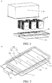
FIG. 1 is an exploded view of a battery pack assembly according to an embodiment of the present invention; -
FIG. 2 is a schematic structural diagram of a tray assembly according to an embodiment of the present invention; -
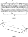
FIG. 3 is a sectional view of a first sub-bottom plate according to an embodiment of the present invention; -
FIG. 4 is an exploded view of a first sub-bottom plate according to an embodiment of the present invention; -
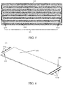
FIG. 5 is a sectional view of a first sub-bottom plate according to another embodiment of the present invention; -
FIG. 6 is an exploded view of a first sub-bottom plate according to another embodiment of the present invention; -
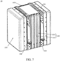
FIG. 7 is a schematic structural diagram of a battery assembly according to an embodiment of the present invention; and -
FIG. 8 is an exploded view of a battery assembly according to an embodiment of the present invention. - Reference numerals of the accompanying drawing:
battery pack assembly 1,tray assembly 10,tray 100,frame 110,bottom plate 120,first sub-bottom plate 121,first part 1211,second part 1212,main body part 1213,seal portion 1214,second sub-bottom plate 122,flow channel 130,channel 131,groove 132,pipe connector 140,connector 150,heat exchange device 160,heat preservation cotton 170,battery assembly 20,battery 210,cooling plate 220,plate body 221,heat pipe 222,batten 230,heat conduction sheet 240, andenclosure 30. - Reference will be made in detail to embodiments of the present invention. The embodiments described herein with reference to drawings are explanatory, illustrative, and should be used to generally understand the present invention. The embodiments described below with reference to the accompanying drawings are exemplary, aiming to explain the present invention, but cannot be understood as a limitation on the present invention.
- In the description of the present invention, it should be understood that, a direction or location relationship indicated by a term "center", "longitudinal", "transverse", "length", "width", "thickness", "upper", "lower", "front", "rear", "horizontal", "top", "bottom", "inner", "outer", "circumference", or the like is a direction or location relationship shown based on the accompanying drawings, and is intended only conveniently describe the present invention and simplify the description, but is not intended to indicate or imply that a mentioned apparatus or element needs to have a particular direction and is constructed and operated in the particular direction. Therefore, the direction or location relationship cannot be understood as a limitation on the present invention.
- In addition, terms "first" and "second" are used only for description objectives, and shall not be construed as indicating or implying relative importance or implying a quantity of indicated technical features. Therefore, a feature restricted by "first" or "second" may explicitly indicate or implicitly include at least one such feature. In the descriptions of the present invention, "multiple" refers to at least two, for example, two, or three, unless otherwise specifically limited in detail.
- In the present invention, unless explicitly specified or limited otherwise, the terms "mounted", "connected", "connection", and "fixed" should be understood broadly, for example, which may be fixed connections, detachable connections or integral connections; may be mechanical connections or electrical connections; may be direct connections, indirectly connected with each other through an intermediate medium, or communications inside two elements or an interaction relationship of two elements, unless otherwise specifically limited. Those of ordinary skill in the art can understand specific meanings of the terms in the present invention according to specific situations.
- In the present invention, unless explicitly specified or limited otherwise, a first characteristic "on" or "under" a second characteristic may be the first characteristic in direct contact with the second characteristic, or the first characteristic in indirect contact with the second characteristic by using an intermediate medium. Moreover, the first characteristic "on", "above " and "over" the second characteristic may be the first characteristic right above or obliquely above the second characteristic, or only indicates that a horizontal height of the first characteristic is greater than that of the second characteristic. The first characteristic "under", "below " and "beneath" the second characteristic may be the first characteristic right below or obliquely below the second characteristic, or only indicates that a horizontal height of the first characteristic is less than that of the second characteristic.
- The present invention is described in detail below with reference to the accompanying drawings and the embodiments.
- First referring to
FIG. 1 to FIG. 6 , atray 100 according to an embodiment of the present invention is described in detail. As shown inFIG. 1 to FIG. 6 , thetray 100 includes aframe 110 and abottom plate 120. Thebottom plate 120 may be connected to theframe 110, theframe 110 is disposed around thebottom plate 120, thebottom plate 120 includes a plurality of sub-bottom plates, flowchannels 130 are provided in at least some sub-bottom plates of the plurality of sub-bottom plates, and abattery assembly 20 is suitable for being mounted on a sub-bottom plate in which aflow channel 130 is provided. - It may be understood that, the
battery assembly 20 is suitable for being supported on the sub-bottom plate of thebottom plate 120 in which theflow channel 130 is provided, so as to perform heat exchange with a heat exchange medium in theflow channel 130, and theframe 110 is used to support thebottom plate 120, to prevent thebottom plate 120 from being deformed. - The
battery assembly 20 may perform heat exchange with the heat exchange medium in theflow channel 130, thereby effectively controlling a temperature of thebattery assembly 20. Optionally, the heat exchange medium may be a cooling liquid (such as water), or may be air. That is, a water cooling mode and an air cooling mode may be compatible in thetray 100. - Based on the
tray 100 according to this embodiment of the present invention, theflow channels 130 are integrated in thetray 100, a volume requirement on the cavity for holding thebattery assembly 20 may be reduced, theflow channels 130 are arranged more concisely, wiring of theflow channels 130 is clearer, and the water cooling mode and the air cooling mode may be compatible simultaneously. Particularly, in the water cooling mode, even if a cooling liquid leaks, the cooling liquid may directly flow outward, thebattery assembly 20 is not short-circuited, thebattery assembly 20 is used more safely, and thetray 100 provided with theflow channels 130 can further implement crumple at the time of encountering collision. This may play a role of relatively well protecting thebattery assembly 20. - Optionally, the
tray 100 may be an aluminum product or an aluminum alloy product. Therefore, thetray 100 has a large strength, good heat conduction performance, and a light weight. - In some optional embodiments of the present invention, the
flow channel 130 may be formed through extrusion. That is, theflow channel 130 may be completely provided in thetray 100, and a circumferential wall of theflow channel 130 may be defined by thetray 100. Therefore, theflow channel 130 has a relatively simple structure, production costs are low, there are a small quantity of obstructions between the heat exchange medium in theflow channel 130 and thebattery assembly 20, and heat exchange efficiency is high. - In some optional embodiments of the present invention, the
sub-bottom plate 120 in which theflow channel 130 is provided and theflow channel 130 inside thesub-bottom plate 120 are integrally formed through injection molding. - In some other optional embodiments of the present invention, the
flow channel 130 may be formed by inserting a metal pipe into a slot of thebottom plate 120. - That is, a slot may be provided on the
bottom plate 120, the shape of the slot may be similar to the shape of theflow channel 130, and the metal pipe adapting to the shape of the slot is inserted into the slot, and theflow channel 130 is formed in the metal pipe. Therefore, a manufacturing technique of theflow channel 130 is relatively simple. - Further, the slot may be provided on a surface of the
bottom plate 120 away from thebattery assembly 20, and the slot may open downward. Therefore, a case in which the cooling liquid flows, when the metal pipe is ruptured, onto thebottom plate 120 to cause thebattery assembly 20 to be short-circuited may be prevented, and thebattery assembly 20 has better safety. - Optionally, the metal pipe may be a copper pipe, the copper pipe has relatively good plasticity and is easily inserted into the slot, and copper pipe has relatively good heat conduction performance. This is favorable to heat exchange between the heat exchange medium and the
battery assembly 20. - In some still other optional embodiments of the present invention, the
sub-bottom plate 120 in which theflow channel 130 is provided may include an upper plate and a lower plate, and the upper plate and the lower plate are connected to define theflow channel 130 between the upper plate and the lower plate. - For example, the slot corresponding to the
flow channel 130 may be fabricated between the upper plate and the lower plate, and theflow channel 130 may be defined after the upper plate is connected to the lower plate. Optionally, the upper plate and the lower plate may be connected through welding, or may be connected by using a thread connection member. - Preferably, as shown in
FIG. 3 andFIG. 5 , theflow channel 130 may be constructed into a wave shape. On thetray 100 having a same size, constructing theflow channel 130 into the wave shape may prolong a flow travel of theflow channel 130, and enhance a heat exchange effect of the heat exchange medium in theflow channel 130. - Preferably, as shown in
FIG. 1 and FIG. 2 , a surface of thebottom plate 120 away from thebattery assembly 20 may be covered withheat preservation cotton 170, so as to selectively reduce heat exchange efficiency of the heat exchange medium in theflow channel 130, thereby controlling the temperature of thebattery assembly 20 more precisely. - Preferably, the plurality of sub-bottom plates of the
bottom plate 120 may include at least onefirst sub-bottom plate 121, thefirst sub-bottom plate 121 may be connected to theframe 110, aflow channel 130 may be provided in thefirst sub-bottom plate 121, and abattery assembly 20 is suitable for being mounted on thefirst sub-bottom plate 121. - It may be understood that, the
bottom plate 120 may include a plurality offirst sub-bottom plates 121 spliced to each other. Therefore, a strength of atray 100 formed through splicing is far higher than a strength of atray 100 formed through stamping, and it is easy to manufacturetrays 100 of various sizes. - In some optional embodiments, the
bottom plate 120 may be completely formed by splicing a plurality offirst sub-bottom plates 121. Therefore, thetray 100 has a good heat exchange effect. - In some other optional embodiments, as shown in
FIG. 2 , thebottom plate 120 may further include at least onesecond sub-bottom plate 122, thesecond sub-bottom plate 122 may be connected to theframe 110, and thesecond sub-bottom plate 122 and thefirst sub-bottom plate 121 are spliced. Further, there may be a plurality ofsecond sub-bottom plates 122 and a plurality offirst sub-bottom plates 121, and the plurality ofsecond sub-bottom plates 122 and the plurality offirst sub-bottom plates 121 may be staggered. - In other words, the
bottom plate 120 may be formed by staggering and splicing the plurality ofsecond sub-bottom plates 122 and the plurality offirst sub-bottom plates 121, and noflow channel 130 is provided in eachsecond sub-bottom plate 122, and thebattery assembly 20 is suitable for being mounted on thefirst sub-bottom plate 121. Therefore, thetray 100 has a lower production cost and a higher strength. - Preferably, as shown in
FIG. 2 , there is a plurality offirst sub-bottom plates 121, and the plurality offirst sub-bottom plates 121 is connected in parallel to a plurality offlow channels 130 in a one-to-one correspondence to the plurality offirst sub-bottom plates 121. - It may be understood that, a
flow channel 130 may be provided in eachfirst sub-bottom plate 121, and an inlet and an outlet of eachflow channel 130 may be independently connected to aheat exchange device 160. Therefore, thefirst sub-bottom plates 121 corresponding to theflow channels 130 have basically same heat exchange efficiency, to ensure that thebattery assemblies 20 have basically consistent temperatures, and thebattery assemblies 20 have long service life and better use performance. - Some optional structures of the
first sub-bottom plate 121 according to this embodiment of the present invention are described below. - In some optional embodiments of the present invention, as shown in
FIG. 3 and FIG. 4 , eachfirst sub-bottom plate 121 may include afirst part 1211 and twosecond parts 1212. - A plurality of
channels 131 may be provided in thefirst part 1211, the twosecond parts 1212 may be respectively disposed at two ends of thefirst part 1211, and at least onegroove 132 opening toward thefirst part 1211 is provided in eachsecond part 1212, and the plurality ofchannels 131 may be in communication by using thegroove 132 to form theflow channel 130. - It may be understood that, the plurality of
channels 131 in thefirst part 1211 may be not in communication with each other, and thegroove 132 provided in thesecond part 1212 may cause some neighboringchannels 131 to be in communication, so that the plurality ofchannels 131 and thegroove 132 jointly form theflow channel 130. - Optionally, the two
second parts 1212 may be respectively welded to the two ends of thefirst part 1211. - Optionally, each of the
first part 1211 and thesecond part 1212 may be an aluminum product or an aluminum alloy product. Therefore, thetray 100 has a large strength, good heat conduction performance, and a light weight. - Optionally, as shown in
FIG. 3 , the plurality ofchannels 131 may be provided in parallel. - Specifically, as shown in
FIG. 3 , sixchannels 131 may be provided in thefirst part 1211. Threegrooves 132 may be provided in onesecond part 1212, afirst groove 132 may be used to cause one end of afirst channel 131 and one end of asecond channel 131 to be in communication, asecond groove 132 may be used to cause one end of athird channel 131 and one end of afourth channel 131 to be in communication, and athird groove 132 may be used to cause one end of afifth channel 131 and one end of asixth channel 131 to be in communication. Fourgrooves 132 may be provided in the other second part 1212.among the fourgrooves 132, afirst groove 132 may be in communication with the other end of thefirst channel 131, asecond groove 132 may be used to be in communication with the other end of thesecond channel 131 and the other end of thethird channel 131, athird groove 132 may be used to be in communication with the other end of thefourth channel 131 and the other end of thefifth channel 131, and afourth groove 132 may be in communication with the other end of thesixth channel 131. Therefore, acomplete flow channel 130 may be formed. - Optionally, as shown in
FIG. 4 , apipe connector 140 may be disposed on eachsecond part 1212, and theheat exchange device 160 may be in communication with theflow channel 130 by using thepipe connector 140. Therefore, theheat exchange device 160 is connected to theflow channel 130 conveniently. - As shown in
FIG. 4 , in an embodiment in which a quantity of thechannels 131 is an even number (such as six), the two ends of theflow channel 130 may be located in a samesecond part 1212. Correspondingly, thesecond part 1212 corresponding to endpoints of theflow channel 130 may be provided with twopipe connectors 140 respectively corresponding to the two ends of theflow channel 130, and the othersecond part 1212 may be provided with apipe connector 140 corresponding to a middle portion of theflow channel 130. That is, the heat exchange medium in theflow channel 130 may flow from the two ends of theflow channel 130 toward the middle portion, or be divided into two branches from the middle portion of theflow channel 130 and flow toward the two ends of theflow channel 130. - In an embodiment in which a quantity of the
channels 131 is an odd number, the two ends of theflow channel 130 may be located in the twosecond parts 1212 in a one-to-one correspondence. Correspondingly, apipe connector 140 may be disposed on eachsecond part 1212, and twopipe connectors 140 respectively correspond to the two ends of theflow channel 130. That is, the heat exchange medium in theflow channel 130 may flow from one end of theflow channel 130 to the other end. - In some other optional embodiments of the present invention, as shown in
FIG. 5 and FIG. 6 , eachfirst sub-bottom plate 121 may include amain body part 1213 and a plurality ofseal portions 1214, a flow path may be provided in themain body part 1213, a middle portion of the flow path may be provided with a plurality of opening portions, and the plurality ofseal portions 1214 may seal the plurality of opening portions in a one-to-one correspondence to form theflow channel 130. - It may be understood that, the shape of the flow path approximates to the shape of the
flow channel 130. For convenience of fabrication, the middle portion of the flow path may be provided with the plurality of opening portions, and theflow channel 130 may be formed after the plurality ofseal portions 1214 seals the plurality of opening portions in a one-to-one correspondence. - As shown in
FIG. 6 , when the two ends of the flow path (or the flow channel 130) are respectively located at two sides of themain body part 1213, twoconnectors 150 may be disposed on themain body part 1213, and the twoconnectors 150 respectively correspond to the two ends of theflow channel 130. That is, the heat exchange medium in theflow channel 130 may flow from one end of theflow channel 130 to the other end. - When the two ends of the flow path (or the flow channel 130) are both located at a same side of the
main body part 1213, threeconnectors 150 may be disposed on themain body part 1213, and the threeconnectors 150 are in a one-to-one correspondence to the two ends of theflow channel 130 and the middle portion of theflow channel 130. That is, the heat exchange medium in theflow channel 130 may flow from the two ends of theflow channel 130 toward the middle portion, or be divided into two branches from the middle portion of theflow channel 130 and flow toward the two ends of theflow channel 130. - Optionally, each
seal portion 1214 may be welded onto themain body part 1213. Therefore, the opening portions may be better sealed, to prevent the cooling liquid from leaking from the opening portions. - Optionally, each of the
main body part 1213 and theseal portion 1214 may be an aluminum product or an aluminum alloy product. Therefore, thetray 100 has a large strength, good heat conduction performance, and a light weight. - To sum up, based on the
tray 100 according to this embodiment of the present invention, theflow channels 130 are integrated in thetray 100, a volume requirement on the cavity for holding thebattery assembly 20 may be reduced, theflow channels 130 are arranged more concisely, wiring of theflow channels 130 is clearer, and the water cooling mode and the air cooling mode may be compatible simultaneously. Particularly, in the water cooling mode, even if a cooling liquid leaks, the cooling liquid may directly flow outward, thebattery assembly 20 is not short-circuited, thebattery assembly 20 is used more safely, and thetray 100 provided with theflow channels 130 can further implement crumple at the time of encountering collision. This may play a role of relatively well protecting thebattery assembly 20. Thetray 100 is formed by splicing extruded profiles, so that thetray 100 has a higher strength, and it may be further convenient to manufacturetrays 100 of various sizes. - A
tray assembly 10 according to an embodiment of the present invention is described below. - As shown in
FIG. 1 to FIG. 6 , thetray assembly 10 includes atray 100 and aheat exchange device 160. Thetray 100 is anytray 100 described in the foregoing embodiment, and aflow channel 130 is provided in abottom plate 120 of thetray 100. The heat exchange medium is suitable for flowing in theflow channel 130, theheat exchange device 160 is connected to theflow channel 130 in thebottom plate 120, and theheat exchange device 160 is used to drive the heat exchange medium to flow in theflow channel 130 to perform heat exchange with thebattery assembly 20. - It may be understood that, the
battery assembly 20 may perform heat exchange with the heat exchange medium in theflow channel 130, and then the heat exchange medium performs heat exchange with theheat exchange device 160, thereby effectively controlling a temperature of thebattery assembly 20. Optionally, the heat exchange medium may be a cooling liquid (such as water), or may be air. That is, a water cooling mode and an air cooling mode may be compatible in thetray assembly 10. - Based on the
tray assembly 10 according to this embodiment of the present invention, theflow channels 130 are integrated in thebottom plate 120 of thetray 100, a volume requirement on the cavity for holding thebattery assembly 20 may be reduced, theflow channels 130 are arranged more concisely, wiring of theflow channels 130 is clearer, and the water cooling mode and the air cooling mode may be compatible simultaneously. Particularly, in the water cooling mode, even if a cooling liquid leaks, the cooling liquid may directly flow outward, thebattery assembly 20 is not short-circuited, thebattery assembly 20 is used more safely, and thetray 100 provided with theflow channels 130 can further implement crumple at the time of encountering collision. This may play a role of relatively well protecting thebattery assembly 20. - A
battery pack assembly 1 according to an embodiment of the present invention is described below. - As shown in
FIG. 1 to FIG. 8 , thebattery pack assembly 1 according to this embodiment of the present invention includes atray 100 and at least onebattery assembly 20, thetray 100 is anytray 100 described in the foregoing embodiment, and eachbattery assembly 20 is mounted on thetray 100. - Based on the
battery pack assembly 1 according to this embodiment of the present invention, by disposing thetray 100 of the foregoing structural form, the volume of thebattery pack assembly 1 may be greatly reduced, theflow channels 130 of thebattery pack assembly 1 are arranged concisely, wiring of theflow channels 130 is clearer, the water cooling mode and the air cooling mode may be compatible simultaneously in thebattery pack assembly 1. Particularly, in the water cooling mode, even if a cooling liquid leaks, the cooling liquid may directly flow outward, thebattery assembly 20 is not short-circuited, thebattery pack assembly 1 is used more safely, and thetray 100 provided with theflow channels 130 can further implement crumple at the time of encountering collision. This may play a role of relatively well protecting thebattery assembly 20. - In some optional embodiments of the present invention, the
battery pack assembly 1 may further include a heat conduction pad (not shown), and the heat conduction pad may be disposed between thetray 100 and thebattery assembly 20. Therefore, the contact area between thebattery assembly 20 and thetray 100 may be increased, to optimize heat exchange efficiency of thebattery pack assembly 1. - Specifically, the heat conduction pad may be paved on the
bottom plate 120 of thetray 100. - Optionally, the heat conduction pad may be constructed into an aluminum or copper sheet.
- Optionally, as shown in
FIG. 1 , thebattery pack assembly 1 may further include anenclosure 30, and theenclosure 30 may be connected to thetray 100, so as to form a cavity suitable for holding thebattery assembly 20. - As shown in
FIG. 1 , theenclosure 30 may be connected to theframe 110 of thetray 100, so as to form a relative enclosed cavity, and thebattery assembly 20 may be disposed in the cavity. - In some optional embodiments of the present invention, as shown in
FIG. 1 ,FIG. 7 andFIG. 8 , eachbattery assembly 20 includes abattery 210 and acooling plate 220, and thebattery 210 may be connected to thetray 100 by using thecooling plate 220. - It may be understood that, the
cooling plate 220 may wrap at least a part of an outer surface of thebattery 210, and thecooling plate 220 may be tightly attached to thetray 100, so as to be favorable to heat exchange between thebattery 210 and thetray 100. Specifically, an outer surface of thecooling plate 220 may be tightly attached to the heat conduction pad, and the heat conduction pad may be tightly attached to thebottom plate 120 of thetray 100. - Preferably, as shown in
FIG. 7 andFIG. 8 , eachbattery assembly 20 may include a plurality of coolingplates 220, and eachbattery assembly 20 may further include abatten 230. The batten 230 may extend along circumference of thebattery 210, and each of the plurality of coolingplates 220 is tightly attached to thebattery 210 and is fastened by using thebatten 230. - It may be understood that, the plurality of cooling
plates 220 is tightly attached to thebattery 210 to wrap at least a part of the outer surface of thebattery 210. For example, eachbattery assembly 20 may include two coolingplates 220, each of the two coolingplates 220 may be constructed into a U-shaped plate, and each of the two coolingplates 220 wraps at least a part of the outer surface of thebattery 210. The batten 230 may be constructed into a U-shaped band, twobattens 230 may cooperate with each other to surround thebattery 210 and fasten the coolingplates 220, and eachbattery assembly 20 may be correspondingly provided with two pairs ofbattens 230. - Preferably, as shown in
FIG. 8 , aheat conduction sheet 240 may be clamped between the coolingplate 220 and thebattery 210, and theheat conduction sheet 240 may be made of a material having good heat conduction performance, such as copper, aluminum, or graphite. - Preferably, as shown in
FIG. 7 andFIG. 8 , thecooling plate 220 may include aplate body 221 and aheat pipe 222, a mounting slot may be provided on theplate body 221, and theheat pipe 222 may be disposed in the mounting slot. Optionally, theheat pipe 222 may be inserted into the mounting slot.therefore, efficiency of heat exchange between thebattery 210 and thecooling plate 220 is high. - Optionally, the
plate body 221 may be an aluminum product or an aluminum alloy product. - Preferably, the mounting slot may include a first mounting slot and a second mounting slot. The first mounting slot may be provided at a side of the
plate body 221 toward thebattery 210, and the first mounting slot may open toward thebattery 210. The second mounting slot may be provided at another side of theplate body 221 away from thebattery 210, and the second mounting slot may open toward a direction away from thebattery 210. - It may be understood that, the
heat pipe 222 disposed in the first mounting slot is used to perform heat exchange between thebattery 210 and theplate body 221, and theheat pipe 222 disposed in the second mounting slot is used to perform heat exchange between theplate body 221 and thetray 100. Therefore, heat exchange efficiency of thebattery pack assembly 1 is high. - Further, there may be a plurality of first mounting slots and a plurality of second mounting slots, and the plurality of second mounting slots and the plurality of first mounting slots may be staggered with each other. Therefore, temperatures of parts of the
plate body 221 are more balanced, and heat exchange efficiency of thebattery pack assembly 1 is high. - To sum up, the
battery pack assembly 1 according to this embodiment of the present invention has a small volume and good heat exchange performance, theflow channels 130 of thebattery pack assembly 1 are arranged concisely, wiring of theflow channels 130 is clearer, the water cooling mode and the air cooling mode may be compatible simultaneously in thebattery pack assembly 1. Particularly, in the water cooling mode, even if a cooling liquid leaks, the cooling liquid may directly flow outward, thebattery assembly 20 is not short-circuited, thebattery pack assembly 1 is used more safely, and thetray 100 provided with theflow channels 130 can further implement crumple at the time of encountering collision. This may play a role of relatively well protecting thebattery assembly 20. - A vehicle according to an embodiment of the present invention is described below.
- As shown in
FIG. 1 to FIG. 8 , the vehicle according to this embodiment of the present invention is provided with anybattery pack assembly 1 described in the foregoing embodiment. - Based on the vehicle according to this embodiment of the present invention, the
battery pack assembly 1 occupies a small mounting space, and thebattery pack assembly 1 of the vehicle has high heat exchange efficiency and is used more safely. - In the descriptions of this specification, a description of a reference term such as "an embodiment", "some embodiments", "an example", "a specific example", or "some examples" means that a specific feature, structure, material, or characteristic that is described with reference to the embodiment or the example is included in at least one embodiment or example of the present invention. In this specification, exemplary descriptions of the foregoing terms do not necessarily refer to a same embodiment or example. In addition, the described specific feature, structure, material, or characteristic may be combined in a proper manner in any one or more embodiments or examples. In addition, with no conflict, a person skilled in the art can integrate and combine different embodiments or examples and features of the different embodiments and examples described in this specification.
- Although the embodiments of the present invention are shown and described above, it can be understood that the foregoing embodiments are exemplary, and should not be construed as limitations to the present invention. A person of ordinary skill in the art can make changes, modifications, replacements, and variations to the foregoing embodiments within the scope of the present invention.
Claims (25)
- A tray, comprising:a bottom plate, wherein the bottom plate comprises a plurality of sub-bottom plates, flow channels are provided in at least some sub-bottom plates of the plurality of sub-bottom plates, and a battery assembly is suitable for being mounted on a sub-bottom plate in which a flow channel is provided; anda frame, wherein the frame is disposed around the bottom plate.
- The tray according to claim 1, wherein the plurality of sub-bottom plates comprises:at least one first sub-bottom plate, wherein the flow channel is provided in the first sub-bottom plate, and the battery assembly is suitable for being mounted on the first sub-bottom plate; andat least one second sub-bottom plate, wherein the second sub-bottom plate and the first sub-bottom plate are spliced.
- The tray according to claim 2, wherein there are a plurality of first sub-bottom plates and a plurality of second sub-bottom plates, and the plurality of second sub-bottom plates and the plurality of first sub-bottom plates are staggered.
- The tray according to claim 2, wherein there is a plurality of first sub-bottom plates, and the plurality of first sub-bottom plates is connected in parallel to a plurality of flow channels in a one-to-one correspondence to the plurality of first sub-bottom plates.
- The tray according to claim 2, wherein the first sub-bottom plate comprises:a first part, wherein a plurality of channels is provided in the first part; andtwo second parts, wherein the two second parts are respectively disposed at two ends of the first part, at least one groove opening toward the first part is provided in each second part, and the plurality of channels is in communication by using the groove to form the flow channel.
- The tray according to claim 5, wherein a pipe connector is disposed on each second part, and the flow channel is suitable for being in communication with a heat exchange device by using the pipe connector.
- The tray according to claim 5, wherein the two second parts are respectively welded to the two ends of the first part.
- The tray according to claim 2, wherein the first sub-bottom plate comprises:a main body part, wherein a flow path is provided in the main body part, and a middle portion of the flow path is provided with a plurality of opening portions; anda plurality of seal portions, wherein the plurality of seal portions seals the plurality of opening portions in a one-to-one correspondence to form the flow channel.
- The tray according to claim 8, wherein each seal portion is welded onto the main body part.
- The tray according to claim 8, wherein at least two connectors are disposed on the main body part, and the heat exchange device is in communication with the flow channel by using the connectors.
- The tray according to claim 1, wherein the sub-bottom plate in which the flow channel is provided and the flow channel inside the sub-bottom plate are integrally formed through injection molding.
- The tray according to claim 1, wherein the flow channel is formed through extrusion.
- The tray according to claim 1, wherein the flow channel is formed by inserting a metal pipe into a slot of the bottom plate.
- The tray according to claim 1, wherein the sub-bottom plate in which the flow channel is provided comprises an upper plate and a lower plate, and the upper plate and the lower plate are connected to define the flow channel between the upper plate and the lower plate.
- The tray according to any one of claims 1 to 10, wherein a surface of the bottom plate away from the battery assembly is covered with heat preservation cotton.
- A tray assembly, comprising:the tray according to any one of claims 1 to 15; anda heat exchange device, wherein the heat exchange device is used to drive a heat exchange medium to flow in the flow channel.
- A battery pack assembly, comprising:at least one battery assembly; andthe tray according to any one of claims 1 to 15, wherein each battery assembly is mounted onto the tray.
- The battery pack assembly according to claim 17, wherein each battery assembly comprises:a battery; anda cooling plate, wherein the battery is connected to the tray by using the cooling plate.
- The battery pack assembly according to claim 18, wherein the cooling plate comprises:a plate body, wherein a mounting slot is provided on the plate body; anda heat pipe, wherein the heat pipe is disposed in the mounting slot.
- The battery pack assembly according to claim 19, wherein the mounting slot comprises:a first mounting slot, wherein the first mounting slot is provided at a side of the plate body toward the battery; anda second mounting slot, wherein the second mounting slot is provided at another side of the plate body away from the battery.
- The battery pack assembly according to claim 20, wherein there are a plurality of first mounting slots and a plurality of second mounting slots, and the plurality of second mounting slots and the plurality of first mounting slots are staggered with each other.
- The battery pack assembly according to claim 18, wherein each battery assembly comprises a plurality of cooling plates, and each battery assembly further comprises:
a batten, wherein the batten extends along circumference of the battery, and each of the plurality of cooling plates is tightly attached to the battery and is fastened by using the batten. - The battery pack assembly according to any one of claims 17 to 22, further comprising:
a heat conduction pad, wherein the heat conduction pad is disposed between the tray and the battery assembly. - The battery pack assembly according to any one of claims 17 to 22, further comprising:
an enclosure, wherein the enclosure is connected to the tray, so as to form a cavity suitable for holding the battery assembly. - A vehicle, provided with the battery pack assembly according to any one of claims 17 to 24.
Applications Claiming Priority (2)
| Application Number | Priority Date | Filing Date | Title |
|---|---|---|---|
| CN201610222401.0A CN107293661A (en) | 2016-04-11 | 2016-04-11 | Trays, pallet assemblies, battery pack assemblies and vehicles |
| PCT/CN2017/078875 WO2017177831A1 (en) | 2016-04-11 | 2017-03-30 | Tray, tray assembly, battery pack assembly, and vehicle |
Publications (2)
| Publication Number | Publication Date |
|---|---|
| EP3429023A1 true EP3429023A1 (en) | 2019-01-16 |
| EP3429023A4 EP3429023A4 (en) | 2019-06-19 |
Family
ID=60042333
Family Applications (1)
| Application Number | Title | Priority Date | Filing Date |
|---|---|---|---|
| EP17781807.7A Withdrawn EP3429023A4 (en) | 2016-04-11 | 2017-03-30 | TRAY, TRAY ASSEMBLY, BATTERY PACK ASSEMBLY, AND VEHICLE |
Country Status (4)
| Country | Link |
|---|---|
| US (1) | US10749223B2 (en) |
| EP (1) | EP3429023A4 (en) |
| CN (3) | CN107546351B (en) |
| WO (1) | WO2017177831A1 (en) |
Cited By (5)
| Publication number | Priority date | Publication date | Assignee | Title |
|---|---|---|---|---|
| EP3654405A1 (en) * | 2018-11-15 | 2020-05-20 | Contemporary Amperex Technology Co., Limited | Casing for battery pack and battery pack |
| CN111959297A (en) * | 2020-08-27 | 2020-11-20 | 华霆(合肥)动力技术有限公司 | Battery pack fixing system and method and battery pack |
| WO2021197989A1 (en) * | 2020-04-03 | 2021-10-07 | Cloud & Heat Technologies GmbH | Temperature-control body housing, temperature-control arrangement, electric device, and use thereof |
| FR3131454A1 (en) * | 2021-12-29 | 2023-06-30 | Safran Electrical & Power | Aircraft electrical box |
| FR3155964A1 (en) * | 2023-11-27 | 2025-05-30 | Safran Electrical & Power | Battery module including a cooling circuit |
Families Citing this family (47)
| Publication number | Priority date | Publication date | Assignee | Title |
|---|---|---|---|---|
| CN106410319A (en) * | 2016-10-09 | 2017-02-15 | 浙江吉利控股集团有限公司 | Integrated liquid-cooling device of battery tray |
| CN107994292A (en) * | 2017-11-27 | 2018-05-04 | 常州常发制冷科技有限公司 | Bottom cold plate for automobile batteries heat dissipation |
| CN108091803B (en) * | 2018-01-18 | 2024-03-29 | 杭州捷能科技有限公司 | Integrated cooling heat-preserving battery system and control method thereof |
| WO2019169080A1 (en) * | 2018-03-01 | 2019-09-06 | Shape Corp. | Cooling system integrated with vehicle battery tray |
| DE102018105526A1 (en) | 2018-03-09 | 2019-09-12 | Benteler Automobiltechnik Gmbh | Method for producing a battery carrier for holding an electric battery module |
| EP3765808A4 (en) * | 2018-03-16 | 2022-05-04 | Romeo Systems, Inc. | COLD PLATE BLADE FOR BATTERY MODULES |
| FR3062749B1 (en) * | 2018-04-10 | 2023-04-14 | Sogefi Air & Cooling | BATTERY UNIT INTEGRATING HEAT EXCHANGE ZONES |
| FR3062521B1 (en) * | 2018-04-10 | 2023-09-08 | Sogefi Air & Cooling | BATTERY UNIT WITH MEANS OF TEMPERATURE REGULATION INTEGRATED IN THE HOUSING |
| GB2575661B (en) * | 2018-07-18 | 2020-08-19 | Flint Eng Ltd | Thermal management system |
| CN110758279B (en) * | 2018-07-27 | 2022-05-13 | 比亚迪股份有限公司 | Integrated Controllers and Vehicles for Vehicles |
| CN109004316A (en) * | 2018-08-09 | 2018-12-14 | 华霆(合肥)动力技术有限公司 | Structure of controlling temperature and battery modules |
| CN109484213A (en) * | 2018-10-24 | 2019-03-19 | 合肥泽尼特新能源有限公司 | A kind of new-energy automobile power store |
| IT201800009787A1 (en) | 2018-10-25 | 2020-04-25 | Italdesign-Giugiaro SPA | System for cooling removable battery modules in an electric or hybrid drive vehicle. |
| FR3096180B1 (en) * | 2019-05-15 | 2022-12-30 | Valeo Systemes Thermiques | “Device for cooling an electrical storage system and method implementing the cooling device” |
| JP7230513B2 (en) * | 2019-01-10 | 2023-03-01 | トヨタ自動車株式会社 | battery pack |
| WO2020177606A1 (en) * | 2019-03-05 | 2020-09-10 | 爱驰汽车有限公司 | Battery pack |
| DE102019108902A1 (en) * | 2019-04-04 | 2020-10-08 | Benteler Automobiltechnik Gmbh | Battery tray with clinch connection |
| CN110209255A (en) * | 2019-05-30 | 2019-09-06 | 北京比特大陆科技有限公司 | Radiator and calculating equipment with it |
| CN112117509B (en) * | 2019-06-21 | 2023-04-07 | 比亚迪股份有限公司 | Power battery pack and vehicle with same |
| CN112133851A (en) * | 2019-06-25 | 2020-12-25 | 比亚迪股份有限公司 | Battery pack and vehicle with same |
| JP7199333B2 (en) * | 2019-10-10 | 2023-01-05 | 株式会社神戸製鋼所 | Battery case for electric vehicle and manufacturing method thereof |
| CN110745377B (en) * | 2019-10-18 | 2024-02-20 | 江苏晟泰集团有限公司 | Cylinder glass piece packing box and packing method thereof |
| US11228070B2 (en) * | 2019-11-11 | 2022-01-18 | Ford Global Technologies, Llc | Efficient electric architectural layouts for electrified vehicles |
| CN112829569A (en) * | 2019-11-22 | 2021-05-25 | 比亚迪股份有限公司 | Bottom protective plate of battery pack tray and vehicle |
| CN111313124B (en) * | 2020-03-19 | 2021-10-01 | 闫延 | Lithium battery high-temperature protection structure and lithium battery |
| CN113540662B (en) * | 2020-03-31 | 2022-10-18 | 比亚迪股份有限公司 | Battery packs and their battery trays, vehicles |
| KR102885971B1 (en) | 2020-04-22 | 2025-11-12 | 주식회사 엘지에너지솔루션 | Battery module and battery pack including the same |
| CN113793996A (en) * | 2020-05-29 | 2021-12-14 | 比亚迪股份有限公司 | Cooling plate assembly, battery pack assembly and vehicle |
| KR102884652B1 (en) | 2020-09-28 | 2025-11-10 | 주식회사 엘지에너지솔루션 | Battery pack and vehicle comprising the battery pack |
| KR20220049870A (en) * | 2020-10-15 | 2022-04-22 | 주식회사 엘지에너지솔루션 | Battery module and battery pack including the same |
| CN112382803B (en) * | 2020-11-11 | 2022-05-31 | 合肥华宇智航动力能源有限公司 | Power battery pack system |
| CN112531267A (en) * | 2020-12-02 | 2021-03-19 | 黄河交通学院 | Lightweight new energy automobile battery package |
| CN112490579A (en) * | 2020-12-16 | 2021-03-12 | 广东和胜新能源汽车配件有限公司 | Battery box |
| CN112803093B (en) * | 2021-01-06 | 2021-11-12 | 武汉理工大学 | Power battery tray and manufacturing method thereof |
| CN115149171A (en) * | 2021-03-30 | 2022-10-04 | 比亚迪股份有限公司 | Battery pack power connection system and vehicle |
| CN115149179B (en) * | 2021-03-30 | 2025-01-14 | 比亚迪股份有限公司 | Battery pack and vehicle |
| CN113154903A (en) * | 2021-04-28 | 2021-07-23 | 苏州汇川技术有限公司 | Radiator manufacturing process and radiator |
| CN113270663B (en) * | 2021-05-18 | 2023-02-17 | 美嘉帕拉斯特汽车零部件(上海)有限公司 | Cooling system of soft package battery of electric vehicle |
| CN113320370B (en) * | 2021-07-01 | 2024-12-27 | 东时(武汉)新能源科技有限公司 | A water cooling plate |
| CN113675494B (en) * | 2021-07-12 | 2023-10-24 | 东风汽车集团股份有限公司 | A heat pipe fin cooling structure applied to power battery modules |
| CN113745690A (en) * | 2021-07-30 | 2021-12-03 | 东风汽车集团股份有限公司 | Integrated cooling battery box, battery package and vehicle |
| WO2023163512A1 (en) * | 2022-02-22 | 2023-08-31 | 주식회사 엘지에너지솔루션 | Battery pack |
| CN116741024B (en) * | 2022-03-03 | 2025-10-17 | 未势能源科技有限公司 | Sample plate assembly for verifying polar plate performance and polar plate experimental device |
| US12580256B2 (en) * | 2022-05-26 | 2026-03-17 | Ford Global Technologies, Llc | Traction battery packs with mixed material tray structures |
| CN115275538A (en) * | 2022-08-17 | 2022-11-01 | 湖北亿纬动力有限公司 | Bottom support assembly, battery module and battery pack |
| CN116014302A (en) * | 2022-12-23 | 2023-04-25 | 浙江极氪智能科技有限公司 | Battery Packs and Vehicles |
| CN219106422U (en) * | 2022-12-23 | 2023-05-30 | 湖北亿纬动力有限公司 | Battery module and electronic equipment |
Family Cites Families (22)
| Publication number | Priority date | Publication date | Assignee | Title |
|---|---|---|---|---|
| JPS5596896A (en) * | 1979-01-17 | 1980-07-23 | Mitsubishi Electric Corp | Total heat exchanger |
| JP4301750B2 (en) * | 2001-08-24 | 2009-07-22 | 三菱重工業株式会社 | Power storage device and management system thereof |
| DE102006050256A1 (en) * | 2006-10-23 | 2008-04-30 | Pahls, Hans-Helmut, Dipl.-Ing. | Cooler i.e. water cooler, for e.g. electronic component i.e. computer, has chambers and nozzles directly arranged in base plate, where medium flows via chambers and nozzles such that heat energy is carried from core and center of cooler |
| EP2124267A3 (en) * | 2008-05-22 | 2012-02-01 | Stichting IMEC Nederland | Thermoelectric generator for implants and embedded devices |
| DE102008027293A1 (en) * | 2008-06-06 | 2009-12-10 | Behr Gmbh & Co. Kg | Device for cooling a vehicle battery |
| EP2443687B1 (en) * | 2009-06-18 | 2017-05-31 | Johnson Controls Advanced Power Solutions LLC | Battery module having a cell tray with thermal management features |
| DE102010056204A1 (en) * | 2010-03-26 | 2011-09-29 | Daimler Ag | Temperature control element for a battery |
| DE102010013025A1 (en) * | 2010-03-26 | 2011-09-29 | Daimler Ag | Vehicle battery e.g. lithium ion battery for hybrid car, has cooling plate arranged in housing for controlling temperature of battery, where plate is provided with molds, and cooling pipe held in molds in force and/or form fit manner |
| JP5631163B2 (en) * | 2010-11-16 | 2014-11-26 | 本田技研工業株式会社 | Battery unit for vehicle |
| DE102011077838A1 (en) * | 2011-06-20 | 2012-12-20 | Behr Gmbh & Co. Kg | Heat exchanger and method for producing a heat exchanger |
| DE102011107007B4 (en) * | 2011-07-09 | 2026-05-07 | Volkswagen Aktiengesellschaft | Arrangement of a traction battery in a motor vehicle |
| DE202012102349U1 (en) | 2011-07-14 | 2012-07-18 | Visteon Global Technologies, Inc. | battery cooler |
| US8999547B2 (en) * | 2011-12-22 | 2015-04-07 | Samsung Sdi Co., Ltd. | Battery module |
| CN103841793A (en) * | 2012-11-22 | 2014-06-04 | 浙江海得新能源有限公司 | Water-cooling heat radiator and producing method |
| CN103346363A (en) * | 2013-06-21 | 2013-10-09 | 华南理工大学 | Compact type electric vehicle battery liquid cooling device |
| US20150263397A1 (en) | 2014-03-13 | 2015-09-17 | Ford Global Technologies, Llc | Side mounted traction battery thermal plate |
| DE102014106941A1 (en) * | 2014-05-16 | 2015-11-19 | Valeo Klimasysteme Gmbh | Cooling device for a battery pack |
| DE102014106954B4 (en) * | 2014-05-16 | 2024-12-24 | Valeo Klimasysteme Gmbh | Device for heating and cooling a battery pack and vehicle drive battery assembly |
| TWI571610B (en) * | 2014-07-11 | 2017-02-21 | 財團法人金屬工業研究發展中心 | Cooling plate and manufacturing method thereof |
| CN204348863U (en) * | 2014-12-18 | 2015-05-20 | 北汽福田汽车股份有限公司 | Water-cooled assembly and the automobile with it |
| CN104567490A (en) * | 2015-01-14 | 2015-04-29 | 上海艾克森集团有限公司 | Filtering type plate heat exchanger |
| CN204905381U (en) * | 2015-09-10 | 2015-12-23 | 江苏风雷光电科技有限公司 | Water -cooling board subassembly based on porous flat pipe |
-
2016
- 2016-04-11 CN CN201710714199.8A patent/CN107546351B/en active Active
- 2016-04-11 CN CN201710701261.XA patent/CN107689435A/en active Pending
- 2016-04-11 CN CN201610222401.0A patent/CN107293661A/en active Pending
-
2017
- 2017-03-30 WO PCT/CN2017/078875 patent/WO2017177831A1/en not_active Ceased
- 2017-03-30 EP EP17781807.7A patent/EP3429023A4/en not_active Withdrawn
- 2017-03-30 US US16/092,573 patent/US10749223B2/en active Active
Cited By (10)
| Publication number | Priority date | Publication date | Assignee | Title |
|---|---|---|---|---|
| EP3654405A1 (en) * | 2018-11-15 | 2020-05-20 | Contemporary Amperex Technology Co., Limited | Casing for battery pack and battery pack |
| US11101519B2 (en) | 2018-11-15 | 2021-08-24 | Contemporary Amperex Technology Co., Limited | Casing for battery pack and battery pack |
| US11495861B2 (en) | 2018-11-15 | 2022-11-08 | Contemporary Amperex Technology Co., Limited | Casing for battery pack and battery pack |
| US11949079B2 (en) | 2018-11-15 | 2024-04-02 | Contemporary Amperex Technology Co., Limited | Casing for battery pack and battery pack |
| WO2021197989A1 (en) * | 2020-04-03 | 2021-10-07 | Cloud & Heat Technologies GmbH | Temperature-control body housing, temperature-control arrangement, electric device, and use thereof |
| CN111959297A (en) * | 2020-08-27 | 2020-11-20 | 华霆(合肥)动力技术有限公司 | Battery pack fixing system and method and battery pack |
| FR3131454A1 (en) * | 2021-12-29 | 2023-06-30 | Safran Electrical & Power | Aircraft electrical box |
| WO2023126591A3 (en) * | 2021-12-29 | 2023-08-17 | Safran Electrical & Power | Electrical housing for an aircraft |
| FR3155964A1 (en) * | 2023-11-27 | 2025-05-30 | Safran Electrical & Power | Battery module including a cooling circuit |
| WO2025114663A1 (en) * | 2023-11-27 | 2025-06-05 | Safran Electrical & Power | Battery module comprising a cooling circuit |
Also Published As
| Publication number | Publication date |
|---|---|
| CN107546351B (en) | 2020-10-23 |
| CN107546351A (en) | 2018-01-05 |
| CN107689435A (en) | 2018-02-13 |
| US20190131674A1 (en) | 2019-05-02 |
| US10749223B2 (en) | 2020-08-18 |
| EP3429023A4 (en) | 2019-06-19 |
| WO2017177831A1 (en) | 2017-10-19 |
| CN107293661A (en) | 2017-10-24 |
Similar Documents
| Publication | Publication Date | Title |
|---|---|---|
| US10749223B2 (en) | Tray, tray assembly, battery pack assembly and vehicle | |
| US9806381B2 (en) | Serpentine cooling element for battery assembly | |
| US10274259B2 (en) | Multi-sided heat exchangers with compliant heat transfer surfaces | |
| JP5540114B2 (en) | Medium or large battery pack with improved cooling efficiency | |
| KR101806447B1 (en) | Battery Pack | |
| CN116169397B (en) | Liquid cooling plate, liquid cooling assembly, battery module and battery pack | |
| KR102731558B1 (en) | High voltage battery apparatus for vehicle | |
| KR101781923B1 (en) | Battery cooler for vehicle | |
| US11296377B2 (en) | Cover for an electrochemical cell with enhanced heat conduction | |
| KR102740793B1 (en) | Temperature control module and battery pack | |
| JP5783465B2 (en) | Busbar and electrical circuit | |
| CA3002577A1 (en) | A structural support element in heat exchangers | |
| KR20130112899A (en) | Temperature-controlled battery | |
| JP2013134993A (en) | Battery module | |
| CN102403474A (en) | Battery module | |
| CN102623771A (en) | Battery cooling plate structure | |
| JP5725316B2 (en) | Secondary battery and battery pack | |
| KR102030143B1 (en) | Double side water cooler | |
| JP2025146732A (en) | Current distribution device, cooling device, battery pack and power consumption device | |
| CN213340555U (en) | Battery box and battery package | |
| JP2012216410A (en) | Battery pack and battery | |
| CN115241564A (en) | Box with integrated liquid cooling system and integrated liquid cooling system | |
| JP2016539454A (en) | Cost effective apparatus and method for controlling the temperature of a motor vehicle battery module | |
| CN111623560B (en) | Heat exchanger | |
| CN106654451B (en) | A kind of cooling device for vehicle |
Legal Events
| Date | Code | Title | Description |
|---|---|---|---|
| STAA | Information on the status of an ep patent application or granted ep patent |
Free format text: STATUS: THE INTERNATIONAL PUBLICATION HAS BEEN MADE |
|
| PUAI | Public reference made under article 153(3) epc to a published international application that has entered the european phase |
Free format text: ORIGINAL CODE: 0009012 |
|
| STAA | Information on the status of an ep patent application or granted ep patent |
Free format text: STATUS: REQUEST FOR EXAMINATION WAS MADE |
|
| 17P | Request for examination filed |
Effective date: 20181011 |
|
| AK | Designated contracting states |
Kind code of ref document: A1 Designated state(s): AL AT BE BG CH CY CZ DE DK EE ES FI FR GB GR HR HU IE IS IT LI LT LU LV MC MK MT NL NO PL PT RO RS SE SI SK SM TR |
|
| AX | Request for extension of the european patent |
Extension state: BA ME |
|
| RIC1 | Information provided on ipc code assigned before grant |
Ipc: H01M 10/625 20140101ALI20190206BHEP Ipc: F28D 15/02 20060101ALN20190206BHEP Ipc: H01M 10/6556 20140101ALI20190206BHEP Ipc: B60L 3/00 20190101AFI20190206BHEP Ipc: B60L 58/26 20190101ALI20190206BHEP Ipc: H01M 2/10 20060101ALI20190206BHEP Ipc: F28F 3/12 20060101ALI20190206BHEP Ipc: H01M 10/647 20140101ALI20190206BHEP Ipc: H01M 10/6568 20140101ALI20190206BHEP Ipc: B60L 50/64 20190101ALI20190206BHEP Ipc: F28F 9/02 20060101ALN20190206BHEP Ipc: H01M 10/613 20140101ALI20190206BHEP |
|
| STAA | Information on the status of an ep patent application or granted ep patent |
Free format text: STATUS: EXAMINATION IS IN PROGRESS |
|
| STAA | Information on the status of an ep patent application or granted ep patent |
Free format text: STATUS: REQUEST FOR EXAMINATION WAS MADE |
|
| A4 | Supplementary search report drawn up and despatched |
Effective date: 20190520 |
|
| RIC1 | Information provided on ipc code assigned before grant |
Ipc: F28D 15/02 20060101ALN20190514BHEP Ipc: H01M 10/6568 20140101ALI20190514BHEP Ipc: H01M 10/6556 20140101ALI20190514BHEP Ipc: B60L 3/00 20190101AFI20190514BHEP Ipc: B60L 50/64 20190101ALI20190514BHEP Ipc: B60L 58/26 20190101ALI20190514BHEP Ipc: F28F 9/02 20060101ALN20190514BHEP Ipc: H01M 10/613 20140101ALI20190514BHEP Ipc: H01M 2/10 20060101ALI20190514BHEP Ipc: F28F 3/12 20060101ALI20190514BHEP Ipc: H01M 10/625 20140101ALI20190514BHEP Ipc: H01M 10/647 20140101ALI20190514BHEP |
|
| 17Q | First examination report despatched |
Effective date: 20190604 |
|
| STAA | Information on the status of an ep patent application or granted ep patent |
Free format text: STATUS: EXAMINATION IS IN PROGRESS |
|
| DAV | Request for validation of the european patent (deleted) | ||
| DAX | Request for extension of the european patent (deleted) | ||
| 17Q | First examination report despatched |
Effective date: 20190715 |
|
| STAA | Information on the status of an ep patent application or granted ep patent |
Free format text: STATUS: THE APPLICATION IS DEEMED TO BE WITHDRAWN |
|
| 18D | Application deemed to be withdrawn |
Effective date: 20210202 |