EP3428491B1 - Valve device - Google Patents
Valve device Download PDFInfo
- Publication number
- EP3428491B1 EP3428491B1 EP18192966.2A EP18192966A EP3428491B1 EP 3428491 B1 EP3428491 B1 EP 3428491B1 EP 18192966 A EP18192966 A EP 18192966A EP 3428491 B1 EP3428491 B1 EP 3428491B1
- Authority
- EP
- European Patent Office
- Prior art keywords
- valve
- face
- seat
- ball
- ball valve
- Prior art date
- Legal status (The legal status is an assumption and is not a legal conclusion. Google has not performed a legal analysis and makes no representation as to the accuracy of the status listed.)
- Active
Links
Images


Classifications
-
- F—MECHANICAL ENGINEERING; LIGHTING; HEATING; WEAPONS; BLASTING
- F16—ENGINEERING ELEMENTS AND UNITS; GENERAL MEASURES FOR PRODUCING AND MAINTAINING EFFECTIVE FUNCTIONING OF MACHINES OR INSTALLATIONS; THERMAL INSULATION IN GENERAL
- F16K—VALVES; TAPS; COCKS; ACTUATING-FLOATS; DEVICES FOR VENTING OR AERATING
- F16K5/00—Plug valves; Taps or cocks comprising only cut-off apparatus having at least one of the sealing faces shaped as a more or less complete surface of a solid of revolution, the opening and closing movement being predominantly rotary
- F16K5/06—Plug valves; Taps or cocks comprising only cut-off apparatus having at least one of the sealing faces shaped as a more or less complete surface of a solid of revolution, the opening and closing movement being predominantly rotary with plugs having spherical surfaces; Packings therefor
- F16K5/0663—Packings
-
- F—MECHANICAL ENGINEERING; LIGHTING; HEATING; WEAPONS; BLASTING
- F16—ENGINEERING ELEMENTS AND UNITS; GENERAL MEASURES FOR PRODUCING AND MAINTAINING EFFECTIVE FUNCTIONING OF MACHINES OR INSTALLATIONS; THERMAL INSULATION IN GENERAL
- F16K—VALVES; TAPS; COCKS; ACTUATING-FLOATS; DEVICES FOR VENTING OR AERATING
- F16K11/00—Multiple-way valves, e.g. mixing valves; Pipe fittings incorporating such valves
- F16K11/02—Multiple-way valves, e.g. mixing valves; Pipe fittings incorporating such valves with all movable sealing faces moving as one unit
- F16K11/08—Multiple-way valves, e.g. mixing valves; Pipe fittings incorporating such valves with all movable sealing faces moving as one unit comprising only taps or cocks
- F16K11/087—Multiple-way valves, e.g. mixing valves; Pipe fittings incorporating such valves with all movable sealing faces moving as one unit comprising only taps or cocks with spherical plug
- F16K11/0873—Multiple-way valves, e.g. mixing valves; Pipe fittings incorporating such valves with all movable sealing faces moving as one unit comprising only taps or cocks with spherical plug the plug being only rotatable around one spindle
- F16K11/0876—Multiple-way valves, e.g. mixing valves; Pipe fittings incorporating such valves with all movable sealing faces moving as one unit comprising only taps or cocks with spherical plug the plug being only rotatable around one spindle one connecting conduit having the same axis as the spindle
-
- F—MECHANICAL ENGINEERING; LIGHTING; HEATING; WEAPONS; BLASTING
- F16—ENGINEERING ELEMENTS AND UNITS; GENERAL MEASURES FOR PRODUCING AND MAINTAINING EFFECTIVE FUNCTIONING OF MACHINES OR INSTALLATIONS; THERMAL INSULATION IN GENERAL
- F16K—VALVES; TAPS; COCKS; ACTUATING-FLOATS; DEVICES FOR VENTING OR AERATING
- F16K31/00—Actuating devices; Operating means; Releasing devices
- F16K31/02—Actuating devices; Operating means; Releasing devices electric; magnetic
- F16K31/04—Actuating devices; Operating means; Releasing devices electric; magnetic using a motor
- F16K31/041—Actuating devices; Operating means; Releasing devices electric; magnetic using a motor for rotating valves
-
- F—MECHANICAL ENGINEERING; LIGHTING; HEATING; WEAPONS; BLASTING
- F16—ENGINEERING ELEMENTS AND UNITS; GENERAL MEASURES FOR PRODUCING AND MAINTAINING EFFECTIVE FUNCTIONING OF MACHINES OR INSTALLATIONS; THERMAL INSULATION IN GENERAL
- F16K—VALVES; TAPS; COCKS; ACTUATING-FLOATS; DEVICES FOR VENTING OR AERATING
- F16K5/00—Plug valves; Taps or cocks comprising only cut-off apparatus having at least one of the sealing faces shaped as a more or less complete surface of a solid of revolution, the opening and closing movement being predominantly rotary
- F16K5/06—Plug valves; Taps or cocks comprising only cut-off apparatus having at least one of the sealing faces shaped as a more or less complete surface of a solid of revolution, the opening and closing movement being predominantly rotary with plugs having spherical surfaces; Packings therefor
- F16K5/0663—Packings
- F16K5/0689—Packings between housing and plug
-
- F—MECHANICAL ENGINEERING; LIGHTING; HEATING; WEAPONS; BLASTING
- F16—ENGINEERING ELEMENTS AND UNITS; GENERAL MEASURES FOR PRODUCING AND MAINTAINING EFFECTIVE FUNCTIONING OF MACHINES OR INSTALLATIONS; THERMAL INSULATION IN GENERAL
- F16K—VALVES; TAPS; COCKS; ACTUATING-FLOATS; DEVICES FOR VENTING OR AERATING
- F16K5/00—Plug valves; Taps or cocks comprising only cut-off apparatus having at least one of the sealing faces shaped as a more or less complete surface of a solid of revolution, the opening and closing movement being predominantly rotary
- F16K5/08—Details
- F16K5/14—Special arrangements for separating the sealing faces or for pressing them together
- F16K5/20—Special arrangements for separating the sealing faces or for pressing them together for plugs with spherical surfaces
- F16K5/201—Special arrangements for separating the sealing faces or for pressing them together for plugs with spherical surfaces with the housing or parts of the housing mechanically pressing the seal against the plug
-
- F—MECHANICAL ENGINEERING; LIGHTING; HEATING; WEAPONS; BLASTING
- F01—MACHINES OR ENGINES IN GENERAL; ENGINE PLANTS IN GENERAL; STEAM ENGINES
- F01P—COOLING OF MACHINES OR ENGINES IN GENERAL; COOLING OF INTERNAL-COMBUSTION ENGINES
- F01P7/00—Controlling of coolant flow
- F01P7/14—Controlling of coolant flow the coolant being liquid
- F01P2007/146—Controlling of coolant flow the coolant being liquid using valves
Definitions
- the present disclosure relates to a valve device in which a concave spherical valve seat is pressed onto a convex spherical ball face, and for example, a technique suitably used for a valve device that controls cooling water as an example of fluid.
- the convex spherical face refers to a spherical shape protruding outward
- the concave spherical face refers to a spherical shape recessed inward.
- a concave spherical seat face of a valve seat is pressed onto a convex spherical ball face of a ball valve to rotate the ball valve, thereby switching communication and non-communication between a valve opening of the ball valve and a seat opening of the valve seat (see, for example, Patent Literature 1).
- a diameter of the seat opening matches a diameter of the valve opening.
- the diameter of the seat opening is larger than the diameter of the valve opening.
- the diameter of the opening is an inner diameter of each opening.
- the seat face of the valve seat is pressed onto the ball face of the ball valve.
- the ball valve rotates at opening/closing and adjustment of the degree of opening.
- the ball face and the seat face slide in contact with each other under pressure.
- the ball face of the ball valve moves with respect to the seat face. For this reason, a site of the ball face in contact with the seat face at opening is different from a site of the ball face in contact with the seat face at closing. On the contrary, since the seat face does not move, the site of the seat face in contact with the ball face at opening is the same as the site of the seat face in contact with the ball face at closing.
- the ball face contacts the seat face only at closing, while the seat face contacts the ball face continuously from closing to full opening.
- the site of the ball face in contact with the seat face at closing is hard to wear.
- the site of the seat face in contact with the ball face at closing slides on the ball face at all times and thus, is susceptible to wear. For this reason, when the valve device is used for a long time, the seat face that ensures a sealing property at closing wears earlier than the ball face that ensures the sealing property at closing, possibly causing leakage at closing.
- the valve seat in Patent Literature 1 is assembled to a holding member using a cylindrical portion attached to the periphery of the valve seat. Since the cylindrical portion in Patent Literature 1 is an individual component for attaching the valve seat to the holding member, the number of components increases.
- the cylindrical portion in Patent Literature 1 forms an annular groove receiving the valve seat, the axial length of the cylindrical portion is larger than the thickness of the valve seat.
- the valve seat is susceptible to wear. For this reason, when the valve seat continues to wear and becomes thinner, the ball valve may directly contacts the cylindrical portion, eliminating the sealing effect of the valve seat.
- Patent literature 2 refers seat for ball or gate valves wherein a valve set ring incorporates a piston-like seal insert which is movable relative to the valve seat holder and so adapted to maintain a constant seating contact with the valve closure ball or gate no matter what pressure differential exists between the line pressure and the valve body cavity pressure.
- An object of the present disclosure is to provide a valve device capable of restricting deterioration in the sealing property due to sliding wear.
- a valve device is mounted in a vehicle, and a seat face 2a of a valve seat 2 is pressed onto a ball face 1a of a ball valve 1 to rotate the ball valve 1, thereby controlling a flow rate or distribution of engine cooling water.
- the valve device includes:
- the ball valve 1 has a valve opening 1b penetrating through the ball valve, and the valve seat 2 has a seat opening 2b penetrating the center of the valve seat 2.
- the ball valve 1 is rotated so as to communicate the valve opening 1b with the seat opening 2b to be opened, and so as not to communicate the valve opening 1b with the seat opening 2b to be closed.
- the valve opening 1b in the embodiment is an ellipse hole extending along the rotating direction of the ball valve 1.
- the valve opening 1b is an ellipse hole having an edge that is parallel to the rotating direction of the ball valve 1.
- the ball valve 1 is rotated by the electrical actuator via the shaft.
- the ball valve 1 is substantially cup-shaped.
- the flow direction of cooling water is not limited, as an example for further understanding, cooling water supplied through the inlet is fed from a cup opening into the inside of the ball valve 1.
- the ball valve 1 is opened, the cooling water fed to the inside of the ball valve 1 is guided to the outlet through an overlapping site of the valve opening 1b and the seat opening 2b.
- the ball valve 1 is made of, for example, resin such as PPS, and the smooth ball face 1a having a convex spherical shape is in slide-contact with at least the valve seat 2. That is, the ball valve 1 has the convex spherical ball face 1a, and is rotated by the electrical actuator.
- the valve seat 2 is a ring body having the seat opening 2b at its center, and is made of resin such as PTFE.
- the concave spherical seat face 2a of the valve seat 2 is pressed onto the ball face 1a of the ball valve 1, and smoothly slides on the ball face 1a.
- the valve seat 2 is supported by the housing 3, and the housing 3 has a support portion that supports the valve seat 2.
- the support portion is configured of:
- the spacer 5 is fixed to, for example, an inner wall of the passage leading to the outlet by press-fitting, and is substantially cylindrical.
- the spring 6 is a compression coil spring, and is assembled in the compressed state.
- the plate 7 is a metal spring washer shaped like a ring-like circular plate.
- the sleeve 8 is a substantially cylindrical passage member that supports the valve seat 2 at one end closer to the ball valve 1 and is inserted into the spacer 5 at the other end farther from the ball valve 1, and serves to guide cooling water passing through the seat opening 2b to the outlet.
- the sleeve 8 is made of a metal material having a high corrosion resistance, such as stainless steel, and at one end of the tubular sleeve 8, a tubular body 8a that locks an outer end of the valve seat 2 from the outer side in the radial direction, and a ring plate 8b that is in press-contact with the opposite face of the seat are integrally provided as means for supporting the valve seat 2.
- the seat opposite face is a face opposite to the seat face 2a of the valve seat 2.
- An outer end of the valve seat 2 in the embodiment is a cylindrical face formed on the outer circumferential edge of the ring-like valve seat 2.
- the tubular body 8a locks the outer end of the valve seat 2 to prevent extension of the valve seat 2, and is shaped like a cylinder that is shorter in the axial direction than in the radial direction.
- the cylindrical face at the outer end of the valve seat 2 is pressed into the inner circumferential face of the tubular body 8a by press-fitting, to prevent the tubular body 8a from expanding in the radially outer direction of the valve seat 2.
- the seat opposite face of the valve seat 2 is a ring-like plane, and the ring plate 8b is provided on the ring-like plane.
- the ring plate 8b extends from the sleeve 8 inserted on the inner side of the spring 6 in a stepped manner outward in the radial direction.
- the inner circumferential face of the tubular body 8a locks the cylindrical face at the outer end of the valve seat 2, keeping the press-contact of the seat opposite face with the ring plate 8b. Keeping the press-contact of the seat opposite face with the ring plate 8b prevents deformation such as warp of the valve seat 2.
- a seal member 9 such as a lip seal is disposed between the sleeve 8 and the spacer 5, and a seal member 10 such as an O ring is disposed between the housing 3 and the spacer 5.
- the site of the seat face 2a in contact with the ball face 1a at opening is different from the site of the seat face 2a in contact with the ball face 1a at closing.
- the configuration will be specifically described below.
- the site of the seat face 2a which is not in contact with the ball face 1a at opening, is provided on the inner side of the seat face 2a.
- the seat face 2a in the embodiment has a site that slides on the opening edge of the valve opening 1b in parallel with the site, on the radially outer side of the seat opening 2b. After a long-term use, the sliding site generates a step D due to wear.
- a diameter ⁇ 2 of the seat opening 2b is made smaller than a diameter ⁇ 1 of the valve opening 1b. That is, given that the diameter of the valve opening 1b is ⁇ 1, and that the diameter of the seat opening 2b is ⁇ 2, the valve device in the embodiment is provided so as to satisfy the relationship ⁇ 1 > ⁇ 2.
- the valve opening 1b in the embodiment is an ellipse hole extending in the rotating direction of the ball valve 1, and has an opening edge extending in parallel in the rotating direction.
- the diameter ⁇ 1 of the valve opening 1b is determined depending on the width of the ball valve 1 in the rotation axial direction.
- the site of the seat face 2a which is not in contact with the ball face 1a at opening, needs to be provided so as to contact the ball face 1a to ensure the sealing property at closing.
- the radially inner side of the seat face 2a needs to reliably contact the ball face 1a at closing.
- a curvature radius R1 of the ball face 1a is equal to or smaller than a curvature radius R2 of the seat face 2a. That is, given that the curvature radius of the ball face 1a is R1 and that the curvature radius of the seat face 2a is R2, the valve device in the embodiment is provided so as to satisfy the relationship R1 ⁇ R2.
- a contact ring A that contacts the ball face 1a only at closing is provided at an end of the seat face 2a on the radially inner side.
- the contact ring A is a seal ring formed using a curvature difference between the convex spherical ball face 1a and the concave spherical seat face 2a.
- the ball face 1a is a convex spherical face
- the seat face 2a is a concave spherical face.
- the curvature radius R1 of the ball face 1a is set to be smaller than the curvature radius R2 of the seat face 2a.
- the contact ring A that contacts the ball face 1a at closing may be provided at only the end of the seat face 2a on the radially inner side.
- the site of the seat face 2a in contact with the ball face 1a at opening is different from the site of the seat face 2a in contact with the ball face 1a at closing. That is, the site of the seat face 2a in contact with the ball face 1a at closing to ensure the sealing property does not contact the ball face 1a at opening.
- the valve opening 1b in the embodiment is an ellipse hole along the rotating direction of the ball valve 1. For this reason, when the ball valve 1 is rotated, the edge of the ellipse hole locally contacts a portion of the seat face 2a, generating the local step D in the seat face 2a due to wear.
- step D occurs in the seat face 2a, since the site of the step D is located on the radially outer side of the contact ring A that ensures the sealing property at closing, the step D does not effect on the sealing property at closing.
- the edge of the ellipse hole forming the valve opening 1b can ensure the sealing property at closing for a long time.
- valve device in the embodiment is provided with the contact ring A that contacts the ball face 1a only at closing, on the radially inner end of the seat face 2a.
- the contact ring A can suppress wear caused by sliding as described above, and can control the contact width between the ball face 1a and the seat face 2a by using the curvature difference between the ball face 1a and the seat face 2a. Accordingly, a load of the spring 6 can be focused on the contact ring A, improving the sealing property between the ball face 1a and the seat face 2a.
- the site of the seat face 2a in contact with the ball face 1a at closing can be limited on the radially inner side of the seat face 2a ensuring the sealing property at closing.
- the valve device includes a rigid body that prevents deformation of the valve seat 2.
- the rigid body locks at least the outer end of the valve seat 2 to prevent the valve seat 2 from extending in the radially outer side, and is provided integrally with the sleeve 8.
- the sleeve 8 including the rigid body is made of metal such as stainless steel, and is provided by press working, trimming, or the like.
- the rigid body locks both of the cylindrical face at the outer end of the valve seat 2 and the seat opposite face.
- the seat opposite face of the valve seat 2 is provided on the flat ring face, and the rigid body is configured of the tubular body 8a that covers the cylindrical face on the outer circumference of the valve seat 2, and the flat ring plate 8b that is in press-contact with the whole seat opposite face that is a flat face.
- the specific example of the tubular body 8a and the ring plate 8b is described in the first embodiment, detailed description thereof is omitted.
- the rigid body locks the valve seat 2, and the valve seat 2 is fixed to the rigid body.
- the technique of coupling the valve seat 2 to the rigid body is not specifically limited, and press-fitting is adopted as an example.
- the tubular body 8a locks at least cylindrical face on the outer end of the valve seat 2.
- the valve seat 2 is made of resin or the like, the radially outer side of the seat face 2a is prevented from extending outward due to the effect of the ball face 1a. That is, the valve seat 2 can be prevented from extending outward, avoiding leakage caused by deformation of the valve seat 2 for a long time.
- the tubular body 8a locks at least cylindrical face on the outer end of the valve seat 2, suppressing deformation of the valve seat 2. For this reason, even when the valve opening 1b of the ball valve 1 is an ellipse hole, the valve seat 2 is not deformed into elliptical shape, preventing leakage caused by deformation of the valve seat 2.
- the curvature radius of the ball face 1a is set to be smaller than the curvature radius of the seat face 2a. Then, the contact site between the seat face 2a and the ball face 1a becomes extremely local, possibly causing deformation such as warp of the valve seat 2 due to the local stress concentration.
- the rigid body in the second embodiment locks the cylindrical face on the outer end of the valve seat 2 as well as the seat opposite face.
- the tubular body 8a locks at least cylindrical face on the outer end of the valve seat 2, in the state where the seat opposite face is in press-contact with the ring plate 8b. For this reason, even when the contact site between the seat face 2a and the ball face 1a becomes extremely local, deformation such as warp of the valve seat 2 can be prevented, avoiding leakage caused by deformation of the valve seat 2 for a long time.
- both of the ball face 1a and the seat face 2a are smooth, and the friction coefficient ⁇ 1 between the ring plate 8b and the valve seat 2 in the rigid body is larger than the friction coefficient ⁇ 2 between the ball valve 1 and the valve seat 2.
- the ball valve 1 can reliably slide on the valve seat 2 at the contact site, suppressing slippage of the valve seat 2 with respect to the ring plate 8b.
- the tubular body 8a is integrally formed with the ring plate 8b.
- the ring plate 8b acts to prevent deformation of the tubular body 8a.
- the ring plate 8b can further prevent deformation of the tubular body 8a.
- Patent Literature 1 discloses a cylindrical portion that covers the valve seat 2.
- the cylindrical portion in Patent Literature 1 is an individual component for assembling the valve seat 2 to the holding member, increasing the number of components.
- the tubular body 8a in the valve device in the embodiment is provided integrally with the sleeve 8 that serves as a guide for the spring 6.
- the sleeve 8 in the embodiment integrally has the portion inserted in the inner side of the spring 6 to guide the spring 6, the tubular body 8a that guides the valve seat 2, and the ring plate 8b that supports the valve seat 2. This can reduce the number of components of the valve device, and improve assembling of the valve device because of the reduction in the number of the components.
- the cylindrical portion disclosed in Patent Literature 1 is a component forming an annular groove that receives the valve seat 2 and thus, the length of the cylindrical portion in the axial direction is formed to be longer than the thickness of the valve seat 2. Thus, when the valve seat 2 wears due to sliding of the ball valve 1, the ball valve 1 may contact the cylindrical portion, eliminating the sealing effect of the valve seat 2.
- the length of the tubular body 8a provided at the end of the sleeve 8 in the axial direction is formed to be smaller than the thickness of the outer circumferential edge of the valve seat 2. That is, a portion of the outer circumferential edge of the valve seat 2 protrudes from the tubular body 8a toward the ball valve 1.
- the ball valve 1 can be prevented from contacting the sleeve 8 to improve long-term reliability of the valve device.
- the valve device in the second embodiment satisfies relationship ⁇ 1 > ⁇ 2 and R1 ⁇ R2.
- the valve device is provided so as to satisfy relationship ⁇ 1 > ⁇ 2 and R1 ⁇ R2.
- the site of the seat face 2a in contact with the ball face 1a at opening is different from the site of the seat face 2a in contact with the ball face 1a at closing, preventing wear of the valve seat 2 for a long time.
- the tubular body 8a can be formed to be short, preventing the ball valve 1 from contacting the sleeve 8 to ensure long-term reliability of the valve device.
- a third embodiment will be described below with reference to FIG. 5 .
- the valve device intentionally guides water pressure to both of the seat face 2a and the seat opposite face of the valve seat 2.
- the configuration will be specifically described below.
- a back pressure space ⁇ in which cooling water flows from the inlet to the inside of the valve device is formed on the side of the seat opposite face.
- the back pressure space ⁇ is a space around the sleeve 8 at which the spring 6 is disposed.
- the back pressure space ⁇ is a space surrounded with the sleeve 8, the plate 7, the ring plate 8b, and the passage wall of the housing 3 leading to the outlet.
- the back pressure space ⁇ communicates with the space that houses the ball valve 1 in the housing 3 via a gap between the housing 3 and the ring plate 8b.
- the space that houses the ball valve 1 communicates with the inlet at all times.
- cooling water is guided from the engine into the back pressure space ⁇ through the inlet.
- the ring plate 8b provided at one end of the sleeve 8 extends from the sleeve 8 to the radially outer side in a stepped manner.
- the pressure of water guided to the back pressure space ⁇ is applied to the face of the ring plate 8b seated by the spring 6.
- the contact ring A that causes only the radially inner side of the seat face 2a to contact the ball face 1a is provided at the portion where the ball face 1a is opposed to the seat face 2a at closing.
- the shape and the contact width of the contact ring A are not specifically limited, a specific example of the contact ring A will be described below.
- the curvature radius of the ball face 1a is smaller than the curvature radius of the seat face 2a. With the configuration, the curvature difference between the ball face 1a and the seat face 2a forms the contact ring A that causes only the end of the seat face 2a on the radially inner side to contact the ball face 1a at closing.
- annular gap ⁇ into which cooling water flows, on the outer circumferential side of the contact ring A, and between the ball valve 1 and the valve seat 2 at closing.
- the annular gap ⁇ communicates with a space that houses the ball valve 1 in the housing 3 and leads to the inlet.
- cooling water is commonly guided to the annular gap ⁇ and the back pressure space a.
- a circulatory system of engine cooling water in a vehicle adopts a well-known sealed pressurized cooling method.
- water pressure rises to, for example, a valve opening pressure of a radiator cap. That is, the pressure of cooling water supplied from the engine to the inlet of the valve device varies.
- the valve device in the embodiment is provided with the back pressure space ⁇ and the annular gap ⁇ , and intentionally guides water pressure to the seat face 2a and the seat opposite face of the valve seat 2 at closing.
- the force to press the valve seat 2 onto the ball valve 1 can be brought closer to only the biasing force of the spring 6, and even when water pressure increases or decreases, a change in the force to press the valve seat 2 onto the ball valve 1 can be suppressed. This can keep a sliding resistance between the ball valve 1 and the valve seat 2 substantially constant.
- the electrical actuator that rotates the ball valve 1 can be reduced in size. Sliding wear can be suppressed to increase long-term reliability of the valve device.
- the curvature radius of the ball face 1a is made smaller than the curvature radius of the seat face 2a, and the curvature difference between the ball face 1a and the seat face 2a forms the contact ring A that contacts the ball face 1a at the radially inner end of the seat face 2a. For this reason, it is no need to process the contact ring A into an annular rib, reducing costs for forming the annular gap ⁇ .
- the valve device applies the pressure of water guided to the back pressure space ⁇ to the ring plate 8b extended at one end of the sleeve 8, acting the pressure onto the seat opposite face via the ring plate 8b.
- cooling water can be guided from the outer circumferential side of the back pressure space ⁇ to the back pressure space a, as well as from the outer circumferential side of the annular gap ⁇ to the annular space. Specifically, cooling water can be directly guided from the space that houses the ball valve 1 in the housing 3 to both the back pressure space ⁇ and the annular gap ⁇ .
- a pressure-receiving projection area in which water pressure is applied to the seat opposite face from the back pressure space ⁇ is the substantially same as a pressure-receiving projection area in which water pressure is applied to the seat face 2a from the annular gap ⁇ .
- a difference between water pressure that acts on the seat opposite face of the valve seat 2 and water pressure that acts on the seat face 2a can be made closer to zero, bringing a force applied to the valve seat 2 by water pressure to almost zero.
- the sliding resistance between the ball valve 1 and the valve seat 2 can be kept more constant, thereby suppressing an increase in the driving force for the ball valve 1 due to an increase in water pressure more reliably.
- the housing 3 of the valve device includes three cooling water outlets.
- the three cooling water outlets are distinguished one another as first to third outlets 11 to 13.
- the first outlet 11 is a cooling water outlet that guides cooling water passing through the engine to a radiator.
- the second outlet 12 is a cooling water outlet that guides cooling water passing through the engine to an air-conditioning heater core.
- the third outlet 13 is a cooling water outlet that guides cooling water passing through the engine to an oil cooler or an oil warmer of a transmission.
- Configuration for opening or closing the first to third outlets 11 to 13 is the same as the valve device disclosed in the first embodiment, and includes:
- the housing 3 is directly assembled to the engine, and the engine attachment face has an inlet 16 that guides cooling water to the inside of the housing 3.
- a valve chamber 17 that communicates with the inlet 16 and houses the ball valve 1 is provided in the housing 3, and a space between the valve chamber 17 and the ball valve 1 is filled with cooling water supplied from the inlet 16.
- the housing 3 has a first outlet passage 11a that guides cooling water from the valve chamber 17 to the first outlet 11, a second outlet passage 12a that guides cooling water from the valve chamber 17 to the second outlet 12, and a third outlet passage (not illustrated) that guides cooling water from the valve chamber 17 to the third outlet 13.
- the first outlet passage 11a is farther from the inlet 16, and the second outlet passage 12a and the third outlet passage are closer to the inlet 16.
- the first outlet passage 11a is a flow path in which cooling water flows from the engine toward the radiator. For this reason, a diameter of the flow path of the first outlet passage 11a is larger than that of the second outlet passage 12a and the third outlet passage so as to flow cooling water at a high flow rate.
- the shaft 14 is disposed so as to pass the center of the valve chamber 17.
- One end of the shaft 14 is rotatably supported via a ball bearing 18 assembled to the housing 3, and the other end of the shaft 14 is rotatably supported via a bearing plate 19 attached to the inlet 16.
- the bearing plate 19 has an opening that allows cooling water to pass.
- the electrical actuator 15 has well-known configuration.
- the electrical actuator 15 is configured as an electric motor that converts electric power into a rotational torque, a deceleration mechanism that decelerates rotation of the electric motor to increase a driving torque of the shaft 14, and a non-contact rotational angle sensor that detects rotational angle of the shaft 14.
- the ball valve 1 is rotated by the electrical actuator 15 via the shaft 14.
- the ball valve 1 is substantially cup-shaped. Describing the flow direction of cooling water, cooling water supplied from the inlet 16 is fed to the inner side of the ball valve 1 through the cup opening. Then, the ball valve 1 is rotated and the valve opening 1b and the seat opening 2b overlap each other, cooling water flows through the overlapping portion. That is, the valve device in the embodiment rotates the ball valve 1 to change the degree of communication between the inlet 16 and the first to third outlets 13.
- the center of a flow path that guides fluid from the outside of the ball valve 1 into the cup is defined as an inlet axis ja.
- the center of a flow path that discharges fluid from the cup of the ball valve 1 to the first outlet passage 11a is defined as an outlet axis j ⁇ .
- one of the inlet axis j ⁇ and the outlet axis j ⁇ is provided in the same direction as the rotational axis of the ball valve 1, and the outlet axis j ⁇ is provided at an obtuse angle relative to the inlet axis ja.
- the ball valve 1 has the cup opening provided in the same direction as the rotational axis of the ball valve 1.
- the rotational axis of the ball valve 1 is provided at an obtuse angle relative to the outlet axis j ⁇ or the inlet axis j ⁇ .
- the cup opening which serves as an inlet for fluid in the ball valve 1, is opened in the rotational axis direction.
- the inlet 16 formed in the housing 3 is also provided in the rotational axis direction of the ball valve 1. In this manner, the inlet axis j ⁇ is the same direction as the rotational axis of the ball valve 1.
- the outlet passage having the largest diameter of the flow path is the first outlet passage 11a that can guide a large quantity of cooling water to the radiator.
- the outlet axis j ⁇ that guides cooling water to the first outlet passage 11a having the largest flow path diameter is provided at an obtuse angle (for example, 100° to 150°) relative to the rotational axis of the ball valve 1.
- the center of a flow path that guides fluid from the inner side of the ball valve 1 to the second outlet passage 12a via the valve opening 1b is defined as a second outlet axis j ⁇ .
- the second outlet axis j ⁇ is formed at right angle relative to the rotational axis.
- the cup opening that guides cooling water to the inside of the ball valve 1 is opened in the rotational axis direction of the ball valve 1.
- the rotational axis of the ball valve 1 is provided at an obtuse angle relative to the outlet axis j ⁇ . That is, the outlet axis j ⁇ is provided at an obtuse angle relative to the inlet axis j ⁇ .
- a bending angle of cooling water that travels from the inlet 16 to the first outlet passage 11a through the inside of the ball valve 1 can be made gentle, reducing a pressure loss of cooling water that travels from the ball valve 1 toward the first outlet passage 11a.
- the valve device can reduce the pressure loss while being downsized.
- the portion of the ball valve 1, which slides on the valve seat 2 has a convex spherical shape and thus, the angle of each of the outlet axis j ⁇ and the second outlet axis j ⁇ with respect to the rotational axis can be flexibly set.
- first outlet passage 11a and the second outlet passage 12a has a limitation in mounting
- the orientation of the first outlet passage 11a and the second outlet passage 12a can be changed so as not to become obstacles, improving the mounting feature of the valve device to vehicles.
- the outlet passage having the largest diameter of the flow path is the first outlet passage 11a that can guide a large quantity of cooling water to the radiator.
- the outlet axis j ⁇ of the first outlet passage 11a having a large flow path diameter is provided at an obtuse angle relative to the inlet axis j ⁇ .
- the bending angle of cooling water travelling from the inlet 16 to the first outlet passage 11a that guides the cooling water to the radiator can be made gentle. For this reason, the pressure loss of a large quantity of cooling water flowing from the engine toward the radiator can be readily suppressed.
- An engine cooler has a cooling water circuit that forcedly circulates cooling water in an engine 21 to cool the engine 21.
- the cooling water circuit has a first circuit that circulates cooling water in the engine 21, a radiator 22, and a water pump 23 in this order, a second circuit that circulates cooling water in the engine 21, a heater core 24 of an air conditioner, and the water pump 23 in this order, and a third circuit that circulates cooling water in the engine 21, a device 25, and the water pump 23 in this order.
- Cooling water is, for example, LLC containing ethylene glycol.
- the heater core 24 exchanges heat between cooling water flowing out of the engine 21 and air, to heat the air.
- the device 25 is, for example, an oil cooler or a turbo charger, and requires heat-exchange with cooling water flowing out of the engine 21.
- the engine 21 includes a cylinder head 26 and a cylinder block 27, and the cylinder head 26 and the cylinder block 27 are provided with a water jacket 28 that circulates cooling water.
- a valve device 29 that controls the flow rate of cooling water is disposed in the cooling water circuit.
- the valve device 29 is disposed at an outlet of the water jacket 28.
- the valve device 29 is a three-direction flow rate adjustment valve that adjusts the flow rate of cooling water in the first circuit, the second circuit, and the third circuit.
- the valve device 29 may be multi-direction flow rate adjustment valve that adjusts the flow rate in three or more directions.
- the cooling water circuit is filled with cooling water by performing a vacuuming process of vacuuming the entire circuit and then, injecting cooling water using the negative pressure.
- the first circuit has a flow path that bypasses the radiator 22, and a reserve tank 22a provided in the middle of the flow path is vacuumed to inject cooling water.
- the valve device 29 includes:
- the housing 3 has a shaft reception hole 33 that penetrates the housing 3 and receives the shaft 14.
- the shaft reception hole 33 penetrates the housing 3, and has an opening communicating with the valve chamber 17.
- the opening of the shaft reception hole 33, which communicates with the valve chamber 17, is referred to as a shaft reception opening 33a.
- the axial direction of the shaft reception hole 33 is defined as a valve shaft direction.
- a side near the valve chamber 17 is defined as one side in the valve shaft direction, and its opposite side is defined as the other side in the valve shaft direction.
- the other end of the shaft reception hole 33 in the valve shaft direction is opposed to an actuator chamber 35 formed between a cover 34 attached to the housing 3 and the housing 3.
- the actuator chamber 35 is a space that houses the gear 36 constituting the deceleration mechanism and so on.
- cup opening of the ball valve 1 is provided as opposed to the shaft reception opening 33a in the valve shaft direction across the ball valve 1.
- the shaft 14 is inserted into the shaft reception hole 33, and is rotatably supported by the ball bearing 18 interposed between the housing 3 and the shaft 14.
- the ball valve 1 is housed in the valve chamber 17 as well as held in the shaft 14, and is rotated with rotation of the shaft 14 to change the flow rate of cooling water flowing from the cup opening to each valve opening 1b.
- the ball valve 1 is fixed to the shaft 14 by inserting the shaft 14 into a shaft hole 14a in the ball valve 1 and fixing the state.
- the opening of the shaft hole 14a is opposed to the shaft reception opening 33a in the valve shaft direction.
- the seal member 31 is disposed between the inner circumferential face of the shaft reception hole 33 and the outer circumferential face of the shaft 14 to seal space on the opposite side to the valve chamber 17 against the valve chamber 17 in a liquid-tight manner.
- the seal member 31 functions to prevent leakage of cooling water from the valve chamber 17 to the actuator chamber 35.
- the seal member 31 is a general shaft seal component having an annular metal portion 31a and an annular rubber portion 31b using the metal portion 31a as a core.
- the rubber portion 31b is made of a rubber material, and has a seal lip that elastically contacts the outer circumferential face of the shaft 14.
- the seal lip has a first lip 44a that protrudes toward the one side in the valve shaft direction, a second lip 44b that protrudes toward the other side in the valve shaft direction, and a third lip 44c provided between the first lip 44a and the second lip 44b. Only the first lip 44a may be provided.
- the shaft reception hole 33 is enlarged in the inner diameter from the other side in the valve shaft direction toward the one side in the valve shaft direction in two stages.
- the first stage is referred to as a middle-diameter rear portion 33b
- the second stage is referred to as a large-diameter rear portion 33c.
- the seal member 31 is disposed at the large-diameter rear portion 33c.
- the face of the seal member 31 at the other side in the valve shaft direction abuts a stepped face between the middle-diameter rear portion 33b and the large-diameter rear portion 33c.
- An inner space of the middle-diameter rear portion 33b slightly communicates with the actuator chamber 35 through a clearance of the ball bearing 18 and however, the seal member 31 prevents leakage of cooling water from the valve chamber 17 to the actuator chamber 35.
- the labyrinth 32 is provided in a gap extending from the valve chamber 17 to the seal member 31 via the shaft reception opening 33a to attenuate kinetic energy of the cooling water travelling toward the seal member 31.
- the labyrinth 32 is formed using a tubular portion 50 that protrudes from an opening edge of the shaft reception opening 33a toward the valve chamber 17 and surrounds the outer circumferential face of the shaft 14 with a clearance C1, and a peripheral wall 51 of the ball valve 1 that is radially opposed to the outer circumferential face 50a of the tubular portion 50 with a clearance C2.
- the housing 3 has the tubular portion 50 that protrudes from the opening edge of the shaft reception opening 33a toward the valve chamber 17.
- the tubular portion 50 protrudes from the inner wall face of the valve chamber 17 toward the one side in the valve shaft direction, and is shaped like a tube that is coaxial with the shaft 14.
- the one end of the large-diameter rear portion 33c in the valve shaft direction defines the shaft reception opening 33a.
- the inner circumferential face 50b of the tubular portion 50 is flush with the inner circumferential face of the large-diameter rear portion 33c.
- the ball valve 1 has a recess 53 formed at a site opposed to the shaft reception opening 33a.
- the recess 53 has the peripheral wall 51 radially opposed to the outer circumferential face of the shaft 14, and a flat face 54 that is perpendicular to the shaft 14 and is opposed to the end face of the tubular portion 50.
- the tubular portion 50 protrudes into the recess 53. That is, the tubular portion 50 and the recess 53 overlap each other in the valve shaft direction, and the tubular portion 50 and the peripheral wall 51 overlap each other in the radial direction.
- the flow of cooling water travelling from the valve chamber 17 toward the seal member 31 must pass through the clearance C2 between the peripheral wall 51 and the outer circumferential face 50a of the tubular portion 50 and a clearance C3 between the flat face 54 and the one-side face of the tubular portion 50 in the valve shaft direction. That is, the flow path from the valve chamber 17 to the seal member 31 through the shaft reception opening 33a meanders to attenuate kinetic energy of cooling water travelling toward the seal member 31.
- the tubular portion 50 has a stopper 56 that locks the ball valve 1 in the rotating direction and limits the rotational range of the ball valve 1 with respect to the housing 3.
- the stopper 56 is provided as a protruding portion that protrudes from the outer circumferential face 50a of the tubular portion 50 toward the outer circumference.
- the stopper 56 can contact the protruding portion 57 provided on the peripheral wall 51 so as to protrude inward, in the rotating direction.
- the ball valve 1 stops its rotation at the position where the stopper 56 contacts the protruding portion 57.
- the valve device 29 includes a labyrinth 32 that attenuates kinetic energy of cooling water travelling from the valve chamber 17 toward the seal member 31 via the shaft reception opening 33a.
- the labyrinth 32 attenuates kinetic energy of cooling water travelling from the valve chamber 17 toward the seal member 31 via the shaft reception opening 33a, reducing a shock caused when cooling water hits against the seal member 31 to prevent peeling of the first lip 44a.
- the valve device 29 is filled with cooling water.
- cooling water forcibly flows into the valve chamber 17.
- a first lip 44a may be peeled by a large shock of the water pressure.
- the labyrinth 32 can present peeling of the first lip 44a.
- the labyrinth 32 is formed by the tubular portion 50 that surrounds the outer periphery of the shaft 14 with the clearance C1, and the peripheral wall 51 radially opposed to the outer circumferential face 50a of the tubular portion 50 with the clearance C2. This can readily form the labyrinth 32.
- the tubular portion 50 has the stopper 56 that limits the rotational range of the ball valve 1.
- a stopper that limits the rotational range of the ball valve 1 is provided in the housing 3 so as to lock a gear 36.
- a stopper that limits the rotational range of the ball valve 1 is provided in the housing 3 so as to lock a gear 36.
- the labyrinth 32 is not limited to the above embodiment.
- a peripheral wall 59 radially opposed to an inner circumferential face 50b of the tubular portion 50 with a clearance C4 may be provided in the ball valve 1.
- an inner circumferential side face of a peripheral groove 60 forms the peripheral wall 59 radially opposed to the inner circumferential face 50b of the tubular portion 50 with the clearance C4, and an outer circumferential side face of the peripheral groove 60 forms the peripheral wall 51 radially opposed to the outer circumferential face 50a of the tubular portion 50 with the clearance C2.
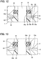
- the labyrinth 32 illustrated in FIG. 12 also can cause the flow path extending from the valve chamber 17 to the seal member 31 via the shaft reception opening 33a to meander, thereby attenuating kinetic energy of cooling water travelling toward the seal member 31.
- the inner diameter of the tubular portion 50 may be larger than the diameter of the shaft reception opening 33a to surround the shaft reception opening 33a.
- the peripheral wall 51 may be omitted. That is, with the configuration, the ball valve 1 has the peripheral wall 59 radially opposed to the inner circumferential face 50b of the tubular portion 50 with the clearance C4 to form the labyrinth 32.
- the ball valve 1 may have a tubular portion 62 inserted into the shaft reception hole 33 to form the labyrinth 32.
- the tubular portion 62 may be disposed such that the first lip 44a is located on the inner side of the tubular portion 62.
- a flange 62a that extends outward may be provided on the other end of the tubular portion 62 in the valve shaft direction, and an inner flange 63 that protrudes inward may be provided on the inner circumferential face of the shaft reception hole 33, which is closer to the one side in the valve shaft direction than the flange 62a.
- the seal member 31 is assembled by being passed on the inner side of the inner flange 63 while being compressively deformed.
- the inner flange 63 as a separate member may be assembled.
- the labyrinth 32 illustrated in FIG. 13 also can cause the flow path extending from the valve chamber 17 to the seal member 31 via the shaft reception opening 33a to meander, thereby attenuating kinetic energy of cooling water travelling toward the seal member 31.
- the ball valve 1 is cup-shaped.
- the ball valve 1 may have any shape as long as the face that slides on the valve seat 2 has a convex spherical shape.
- the ball valve 1 and the valve seat 2 may be made of resin.
- the material for the ball valve 1 and the valve seat 2 is not limited.
- the curvature radius R1 of the ball face 1a is smaller than the curvature radius R2 of the seat face 2a.
- the curvature radius R1 of the ball face 1a may be equal to the curvature radius R2 of the seat face 2a.
- the curvature difference between the ball face 1a and the seat face 2a forms the contact ring A.
- the contact ring A may be formed in any suitable manner.
- the contact ring A may be provided by forming an annular rib on the radially inner side of the seat face 2a.
- the sleeve 8 is fixed to the valve seat 2 by press-fitting.
- the sleeve 8 may be fixed to the valve seat 2 using an adhesive, for example.
- fluid flows from the inner side to the outer side of the ball valve 1 at opening.
- fluid may flow in the opposite direction.
- the electrical actuator 15 rotates the ball valve 1.
- the ball valve 1 may be driven by any means.
- the compression coil spring is used as an example of the spring 6.
- the ball valve 1 and the valve seat 2 may be compressed by any means.
- the present disclosure is applied to the valve device that controls engine cooling water.
- the present disclosure may be applied to a valve device that controls cooling water in a vehicle including no engine.
- the present disclosure is applied to the valve device that controls liquid.
- fluid is not limited to liquid, and the present disclosure may be applied to a valve device that controls gas.
Description
- The present disclosure relates to a valve device in which a concave spherical valve seat is pressed onto a convex spherical ball face, and for example, a technique suitably used for a valve device that controls cooling water as an example of fluid. The convex spherical face refers to a spherical shape protruding outward, and the concave spherical face refers to a spherical shape recessed inward.
- In a conventional valve device, a concave spherical seat face of a valve seat is pressed onto a convex spherical ball face of a ball valve to rotate the ball valve, thereby switching communication and non-communication between a valve opening of the ball valve and a seat opening of the valve seat (see, for example, Patent Literature 1).
- In the conventional valve device, a diameter of the seat opening matches a diameter of the valve opening. Alternatively, the diameter of the seat opening is larger than the diameter of the valve opening. The diameter of the opening is an inner diameter of each opening.
- The seat face of the valve seat is pressed onto the ball face of the ball valve. The ball valve rotates at opening/closing and adjustment of the degree of opening. Thus, the ball face and the seat face slide in contact with each other under pressure.
- Here, the ball face of the ball valve moves with respect to the seat face. For this reason, a site of the ball face in contact with the seat face at opening is different from a site of the ball face in contact with the seat face at closing. On the contrary, since the seat face does not move, the site of the seat face in contact with the ball face at opening is the same as the site of the seat face in contact with the ball face at closing.
- That is, at closing of the valve, the ball face contacts the seat face only at closing, while the seat face contacts the ball face continuously from closing to full opening. Thus, the site of the ball face in contact with the seat face at closing is hard to wear.
- On the contrary, the site of the seat face in contact with the ball face at closing slides on the ball face at all times and thus, is susceptible to wear. For this reason, when the valve device is used for a long time, the seat face that ensures a sealing property at closing wears earlier than the ball face that ensures the sealing property at closing, possibly causing leakage at closing.
- The valve seat in
Patent Literature 1 is assembled to a holding member using a cylindrical portion attached to the periphery of the valve seat. Since the cylindrical portion inPatent Literature 1 is an individual component for attaching the valve seat to the holding member, the number of components increases. - Further, since the cylindrical portion in
Patent Literature 1 forms an annular groove receiving the valve seat, the axial length of the cylindrical portion is larger than the thickness of the valve seat. As described above, in the valve device having the conventional configuration, the valve seat is susceptible to wear. For this reason, when the valve seat continues to wear and becomes thinner, the ball valve may directly contacts the cylindrical portion, eliminating the sealing effect of the valve seat. -
Patent literature 2 refers seat for ball or gate valves wherein a valve set ring incorporates a piston-like seal insert which is movable relative to the valve seat holder and so adapted to maintain a constant seating contact with the valve closure ball or gate no matter what pressure differential exists between the line pressure and the valve body cavity pressure. -
- Patent Literature 1 :
JP 2008-232260 A - Patent Literature 2 :
US 3,667,727 A1 - An object of the present disclosure is to provide a valve device capable of restricting deterioration in the sealing property due to sliding wear.
- This object is achieved with the valve device according to
claim 1. - The above and other objects, features, and advantages of the present disclosure will be more apparent from following description with reference to appended figures.
-
FIG. 1 is a sectional view illustrating a valve device at opening (a first embodiment). -
FIG. 2 is a sectional view illustrating the valve device at closing (the first embodiment). -
FIG. 3 is a view illustrating a contact site of a ball face and a seat face (the first embodiment). -
FIG. 4 is a sectional view illustrating a valve device at opening (a second embodiment). -
FIG. 5 is a sectional view illustrating a valve device at closing (a third embodiment, which is in accordance with the appended claims). -
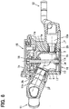
FIG. 6 is a sectional view illustrating a valve device taken along an axial direction (a fourth embodiment). -
FIG. 7 is a view illustrating the valve device when viewed in an axial direction (the fourth embodiment). -
FIG. 8 is a schematic view illustrating an engine cooler (a fifth embodiment). -
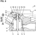
FIG. 9 is a sectional view illustrating a valve device (the fifth embodiment). -
FIG. 10 is a partial enlarged view ofFIG. 9 (the fifth embodiment). -
FIG. 11 is a sectional view taken along XI-XI inFIG. 10 (the fifth embodiment). -
FIG. 12 is a sectional view illustrating a valve device (a modification of the fifth embodiment). -
FIG. 13 is a sectional view illustrating a valve device (a modification of the fifth embodiment). - Of the embodiments described below, only the third is according to the present invention as defined in the appended claims. The embodiments are specific examples, and as a matter of course, the present disclosure is not limited to the embodiments.
- As illustrated in
FIG. 1 to FIG. 3 , a valve device is mounted in a vehicle, and aseat face 2a of avalve seat 2 is pressed onto aball face 1a of aball valve 1 to rotate theball valve 1, thereby controlling a flow rate or distribution of engine cooling water. - The valve device includes:
- a
housing 3 having an inlet through which cooling water is guided from an engine, and an outlet through which the cooling water is discharged, the cooling water being controlled in amount in the valve device; - a shaft rotatably supported with respect to the
housing 3; - an electrical actuator that rotates the shaft;
- a
ball valve 1 that rotates integrally with the shaft; and - a ring-
shaped valve seat 2 pressed onto theball valve 1. - Specifically, the
ball valve 1 has a valve opening 1b penetrating through the ball valve, and thevalve seat 2 has a seat opening 2b penetrating the center of thevalve seat 2. Theball valve 1 is rotated so as to communicate the valve opening 1b with the seat opening 2b to be opened, and so as not to communicate thevalve opening 1b with the seat opening 2b to be closed. - As illustrated in
FIG. 3 , the valve opening 1b in the embodiment is an ellipse hole extending along the rotating direction of theball valve 1. Specifically, thevalve opening 1b is an ellipse hole having an edge that is parallel to the rotating direction of theball valve 1. - The
ball valve 1 is rotated by the electrical actuator via the shaft. For example, theball valve 1 is substantially cup-shaped. Although the flow direction of cooling water is not limited, as an example for further understanding, cooling water supplied through the inlet is fed from a cup opening into the inside of theball valve 1. When theball valve 1 is opened, the cooling water fed to the inside of theball valve 1 is guided to the outlet through an overlapping site of the valve opening 1b and the seat opening 2b. - The
ball valve 1 is made of, for example, resin such as PPS, and thesmooth ball face 1a having a convex spherical shape is in slide-contact with at least thevalve seat 2. That is, theball valve 1 has the convexspherical ball face 1a, and is rotated by the electrical actuator. - The
valve seat 2 is a ring body having theseat opening 2b at its center, and is made of resin such as PTFE. The concavespherical seat face 2a of thevalve seat 2 is pressed onto theball face 1a of theball valve 1, and smoothly slides on theball face 1a. - The
valve seat 2 is supported by thehousing 3, and thehousing 3 has a support portion that supports thevalve seat 2. - The support portion is configured of:
- a
spacer 5 fixed to a passage wall of thehousing 3; - a
spring 6 disposed between thevalve seat 2 and thespacer 5; - a
plate 7 disposed between thespring 6 and thespacer 5; and - a
sleeve 8 that supports thevalve seat 2. - The
spacer 5 is fixed to, for example, an inner wall of the passage leading to the outlet by press-fitting, and is substantially cylindrical. For example, thespring 6 is a compression coil spring, and is assembled in the compressed state. Theplate 7 is a metal spring washer shaped like a ring-like circular plate. - The
sleeve 8 is a substantially cylindrical passage member that supports thevalve seat 2 at one end closer to theball valve 1 and is inserted into thespacer 5 at the other end farther from theball valve 1, and serves to guide cooling water passing through theseat opening 2b to the outlet. - Specifically, the
sleeve 8 is made of a metal material having a high corrosion resistance, such as stainless steel, and at one end of thetubular sleeve 8, atubular body 8a that locks an outer end of thevalve seat 2 from the outer side in the radial direction, and aring plate 8b that is in press-contact with the opposite face of the seat are integrally provided as means for supporting thevalve seat 2. The seat opposite face is a face opposite to theseat face 2a of thevalve seat 2. - A more specific example will be described below. An outer end of the
valve seat 2 in the embodiment is a cylindrical face formed on the outer circumferential edge of the ring-like valve seat 2. Thetubular body 8a locks the outer end of thevalve seat 2 to prevent extension of thevalve seat 2, and is shaped like a cylinder that is shorter in the axial direction than in the radial direction. The cylindrical face at the outer end of thevalve seat 2 is pressed into the inner circumferential face of thetubular body 8a by press-fitting, to prevent thetubular body 8a from expanding in the radially outer direction of thevalve seat 2. - The seat opposite face of the
valve seat 2 is a ring-like plane, and thering plate 8b is provided on the ring-like plane. Specifically, thering plate 8b extends from thesleeve 8 inserted on the inner side of thespring 6 in a stepped manner outward in the radial direction. The inner circumferential face of thetubular body 8a locks the cylindrical face at the outer end of thevalve seat 2, keeping the press-contact of the seat opposite face with thering plate 8b. Keeping the press-contact of the seat opposite face with thering plate 8b prevents deformation such as warp of thevalve seat 2. - A
seal member 9 such as a lip seal is disposed between thesleeve 8 and thespacer 5, and aseal member 10 such as an O ring is disposed between thehousing 3 and thespacer 5. - In the valve device, the site of the
seat face 2a in contact with theball face 1a at opening is different from the site of theseat face 2a in contact with theball face 1a at closing. The configuration will be specifically described below. - In the valve device, to differentiate the site of the
seat face 2a in contact with theball face 1a at opening from the site of theseat face 2a in contact with theball face 1a at closing, the site of theseat face 2a, which is not in contact with theball face 1a at opening, is provided on the inner side of theseat face 2a. - Specifically, the
seat face 2a in the embodiment has a site that slides on the opening edge of thevalve opening 1b in parallel with the site, on the radially outer side of theseat opening 2b. After a long-term use, the sliding site generates a step D due to wear. - As a specific means, a diameter Φ2 of the
seat opening 2b is made smaller than a diameter Φ1 of thevalve opening 1b. That is, given that the diameter of thevalve opening 1b is Φ1, and that the diameter of theseat opening 2b is Φ2, the valve device in the embodiment is provided so as to satisfy the relationship Φ1 > Φ2. - Here, as described above, the
valve opening 1b in the embodiment is an ellipse hole extending in the rotating direction of theball valve 1, and has an opening edge extending in parallel in the rotating direction. Thus, as illustrated inFIG. 3 , the diameter Φ1 of thevalve opening 1b is determined depending on the width of theball valve 1 in the rotation axial direction. - In the valve device in the embodiment, to differentiate the site of the
seat face 2a in contact with theball face 1a at opening from the site of theseat face 2a in contact with theball face 1a at closing, the site of theseat face 2a, which is not in contact with theball face 1a at opening, needs to be provided so as to contact theball face 1a to ensure the sealing property at closing. Specifically, the radially inner side of theseat face 2a needs to reliably contact theball face 1a at closing. - Thus, a curvature radius R1 of the
ball face 1a is equal to or smaller than a curvature radius R2 of theseat face 2a. That is, given that the curvature radius of theball face 1a is R1 and that the curvature radius of theseat face 2a is R2, the valve device in the embodiment is provided so as to satisfy the relationship R1 ≤R2. - As a specific example, in the embodiment, a contact ring A that contacts the
ball face 1a only at closing is provided at an end of theseat face 2a on the radially inner side. The contact ring A is a seal ring formed using a curvature difference between the convexspherical ball face 1a and the concavespherical seat face 2a. - Specifically, as mentioned above, the
ball face 1a is a convex spherical face, and theseat face 2a is a concave spherical face. In the embodiment, the curvature radius R1 of theball face 1a is set to be smaller than the curvature radius R2 of theseat face 2a. - In this manner, using the curvature difference between the
ball face 1a and theseat face 2a, the contact ring A that contacts theball face 1a at closing may be provided at only the end of theseat face 2a on the radially inner side. - In the valve device in the embodiment, the site of the
seat face 2a in contact with theball face 1a at opening is different from the site of theseat face 2a in contact with theball face 1a at closing. That is, the site of theseat face 2a in contact with theball face 1a at closing to ensure the sealing property does not contact theball face 1a at opening. - Thus, wear of the site of the
seat face 2a in contact with theball face 1a at closing to ensure the sealing property can be suppressed for a long time, ensuring the sealing property at closing for a long time. Thus, long-term reliability of the valve device can be increased. - As described above, the
valve opening 1b in the embodiment is an ellipse hole along the rotating direction of theball valve 1. For this reason, when theball valve 1 is rotated, the edge of the ellipse hole locally contacts a portion of theseat face 2a, generating the local step D in theseat face 2a due to wear. - However, even when the step D occurs in the
seat face 2a, since the site of the step D is located on the radially outer side of the contact ring A that ensures the sealing property at closing, the step D does not effect on the sealing property at closing. - As described above, in the embodiment, even when the step D occurs in the
seat face 2a, the edge of the ellipse hole forming thevalve opening 1b can ensure the sealing property at closing for a long time. - As described above, the valve device in the embodiment is provided with the contact ring A that contacts the
ball face 1a only at closing, on the radially inner end of theseat face 2a. - The contact ring A can suppress wear caused by sliding as described above, and can control the contact width between the
ball face 1a and theseat face 2a by using the curvature difference between theball face 1a and theseat face 2a. Accordingly, a load of thespring 6 can be focused on the contact ring A, improving the sealing property between theball face 1a and theseat face 2a. - Even when the contact width of the contact ring A slightly increases due to wear after long-term use, the site of the
seat face 2a in contact with theball face 1a at closing can be limited on the radially inner side of theseat face 2a ensuring the sealing property at closing. - A second embodiment will be described below with reference to
FIG. 4 . - Each of following embodiments adopt the mode in the first embodiment, and only differences between the embodiments and the first embodiment will be described below. The elements having the same function in following embodiments as the element in the first embodiment are given the same reference numerals.
- The valve device includes a rigid body that prevents deformation of the
valve seat 2. The rigid body locks at least the outer end of thevalve seat 2 to prevent thevalve seat 2 from extending in the radially outer side, and is provided integrally with thesleeve 8. Specifically, thesleeve 8 including the rigid body is made of metal such as stainless steel, and is provided by press working, trimming, or the like. - Here, the rigid body locks both of the cylindrical face at the outer end of the
valve seat 2 and the seat opposite face. Specifically, the seat opposite face of thevalve seat 2 is provided on the flat ring face, and the rigid body is configured of thetubular body 8a that covers the cylindrical face on the outer circumference of thevalve seat 2, and theflat ring plate 8b that is in press-contact with the whole seat opposite face that is a flat face. The specific example of thetubular body 8a and thering plate 8b is described in the first embodiment, detailed description thereof is omitted. - As described above, the rigid body locks the
valve seat 2, and thevalve seat 2 is fixed to the rigid body. The technique of coupling thevalve seat 2 to the rigid body is not specifically limited, and press-fitting is adopted as an example. - As described above, in the valve device, the
tubular body 8a locks at least cylindrical face on the outer end of thevalve seat 2. Thus, even when thevalve seat 2 is made of resin or the like, the radially outer side of theseat face 2a is prevented from extending outward due to the effect of theball face 1a. That is, thevalve seat 2 can be prevented from extending outward, avoiding leakage caused by deformation of thevalve seat 2 for a long time. - As described above, in the valve device, the
tubular body 8a locks at least cylindrical face on the outer end of thevalve seat 2, suppressing deformation of thevalve seat 2. For this reason, even when thevalve opening 1b of theball valve 1 is an ellipse hole, thevalve seat 2 is not deformed into elliptical shape, preventing leakage caused by deformation of thevalve seat 2. - In the valve device, the curvature radius of the
ball face 1a is set to be smaller than the curvature radius of theseat face 2a. Then, the contact site between theseat face 2a and theball face 1a becomes extremely local, possibly causing deformation such as warp of thevalve seat 2 due to the local stress concentration. - However, the rigid body in the second embodiment locks the cylindrical face on the outer end of the
valve seat 2 as well as the seat opposite face. Specifically, thetubular body 8a locks at least cylindrical face on the outer end of thevalve seat 2, in the state where the seat opposite face is in press-contact with thering plate 8b. For this reason, even when the contact site between theseat face 2a and theball face 1a becomes extremely local, deformation such as warp of thevalve seat 2 can be prevented, avoiding leakage caused by deformation of thevalve seat 2 for a long time. - In the valve device, both of the
ball face 1a and theseat face 2a are smooth, and the friction coefficient µ1 between thering plate 8b and thevalve seat 2 in the rigid body is larger than the friction coefficient µ2 between theball valve 1 and thevalve seat 2. - Accordingly, at rotation of the
ball valve 1, theball valve 1 can reliably slide on thevalve seat 2 at the contact site, suppressing slippage of thevalve seat 2 with respect to thering plate 8b. - The
tubular body 8a is integrally formed with thering plate 8b. Thus, even when thetubular body 8a is relatively thin, thering plate 8b acts to prevent deformation of thetubular body 8a. Thus, for example, even when thetubular body 8a is thin and thus, thetubular body 8a alone lacks in strength, thering plate 8b can further prevent deformation of thetubular body 8a. - That is, even when the rigid body is relatively thin, combination of the
tubular body 8a and thering plate 8b can effectively prevent the deformation of thevalve seat 2. -
Patent Literature 1 discloses a cylindrical portion that covers thevalve seat 2. The cylindrical portion inPatent Literature 1 is an individual component for assembling thevalve seat 2 to the holding member, increasing the number of components. - On the contrary, the
tubular body 8a in the valve device in the embodiment is provided integrally with thesleeve 8 that serves as a guide for thespring 6. Specifically, thesleeve 8 in the embodiment integrally has the portion inserted in the inner side of thespring 6 to guide thespring 6, thetubular body 8a that guides thevalve seat 2, and thering plate 8b that supports thevalve seat 2. This can reduce the number of components of the valve device, and improve assembling of the valve device because of the reduction in the number of the components. - The cylindrical portion disclosed in
Patent Literature 1 is a component forming an annular groove that receives thevalve seat 2 and thus, the length of the cylindrical portion in the axial direction is formed to be longer than the thickness of thevalve seat 2. Thus, when thevalve seat 2 wears due to sliding of theball valve 1, theball valve 1 may contact the cylindrical portion, eliminating the sealing effect of thevalve seat 2. - On the contrary, according to the present embodiment, the length of the
tubular body 8a provided at the end of thesleeve 8 in the axial direction is formed to be smaller than the thickness of the outer circumferential edge of thevalve seat 2. That is, a portion of the outer circumferential edge of thevalve seat 2 protrudes from thetubular body 8a toward theball valve 1. - Thus, even when the
valve seat 2 wears due to sliding of theball valve 1, theball valve 1 can be prevented from contacting thesleeve 8 to improve long-term reliability of the valve device. - The above-mentioned advantage will be described more specifically.
- As described in the first embodiment, the valve device in the second embodiment satisfies relationship Φ1 > Φ2 and R1 ≤ R2. As a specific example, the valve device is provided so as to satisfy relationship Φ1 > Φ2 and R1 < R2.
- For this reason, as described in the
advantage 1 in the first embodiment, the site of theseat face 2a in contact with theball face 1a at opening is different from the site of theseat face 2a in contact with theball face 1a at closing, preventing wear of thevalve seat 2 for a long time. - In addition to the advantage, in the second embodiment, by setting the axial length of the
tubular body 8a to be smaller than the thickness of the outer circumferential edge of thevalve seat 2, a portion of the outer circumferential edge of thevalve seat 2 protrudes from thetubular body 8a toward theball valve 1. - For this reason, even when the
valve seat 2 that suppresses wear because of the advantage of the first embodiment wears after long-term use, thetubular body 8a can be formed to be short, preventing theball valve 1 from contacting thesleeve 8 to ensure long-term reliability of the valve device. - A third embodiment will be described below with reference to
FIG. 5 . At closing, the valve device intentionally guides water pressure to both of theseat face 2a and the seat opposite face of thevalve seat 2. The configuration will be specifically described below. A back pressure space α in which cooling water flows from the inlet to the inside of the valve device is formed on the side of the seat opposite face. - Specifically, the back pressure space α is a space around the
sleeve 8 at which thespring 6 is disposed. In more detail, the back pressure space α is a space surrounded with thesleeve 8, theplate 7, thering plate 8b, and the passage wall of thehousing 3 leading to the outlet. The back pressure space α communicates with the space that houses theball valve 1 in thehousing 3 via a gap between thehousing 3 and thering plate 8b. The space that houses theball valve 1 communicates with the inlet at all times. Thus, as represented by a broken arrow X in the figure, cooling water is guided from the engine into the back pressure space α through the inlet. - Here, the
ring plate 8b provided at one end of thesleeve 8 extends from thesleeve 8 to the radially outer side in a stepped manner. As a result, the pressure of water guided to the back pressure space α is applied to the face of thering plate 8b seated by thespring 6. - As a result, as the water pressure increases, the force to press the
valve seat 2 onto theball valve 1 becomes larger. - The contact ring A that causes only the radially inner side of the
seat face 2a to contact theball face 1a is provided at the portion where theball face 1a is opposed to theseat face 2a at closing. - Although the shape and the contact width of the contact ring A are not specifically limited, a specific example of the contact ring A will be described below. In the embodiment, the curvature radius of the
ball face 1a is smaller than the curvature radius of theseat face 2a. With the configuration, the curvature difference between theball face 1a and theseat face 2a forms the contact ring A that causes only the end of theseat face 2a on the radially inner side to contact theball face 1a at closing. - Providing the contact ring A forms an annular gap β, into which cooling water flows, on the outer circumferential side of the contact ring A, and between the
ball valve 1 and thevalve seat 2 at closing. The annular gap β communicates with a space that houses theball valve 1 in thehousing 3 and leads to the inlet. Thus, as represented by a broken arrow Y, cooling water is commonly guided to the annular gap β and the back pressure space a. - The pressure of water guided to the annular gap β is applied to the
seat face 2a. As a result, as water pressure increases, a force to separate thevalve seat 2 from theball valve 1 becomes larger. - A circulatory system of engine cooling water in a vehicle adopts a well-known sealed pressurized cooling method. In the method, when the engine is driven to increase water temperature, water pressure rises to, for example, a valve opening pressure of a radiator cap. That is, the pressure of cooling water supplied from the engine to the inlet of the valve device varies.
- As described above, the valve device in the embodiment is provided with the back pressure space α and the annular gap β, and intentionally guides water pressure to the
seat face 2a and the seat opposite face of thevalve seat 2 at closing. - This can offset the force applied from the seat opposite face to the
valve seat 2 and the force applied from theseat face 2a to thevalve seat 2 each other. - Thus, the force to press the
valve seat 2 onto theball valve 1 can be brought closer to only the biasing force of thespring 6, and even when water pressure increases or decreases, a change in the force to press thevalve seat 2 onto theball valve 1 can be suppressed. This can keep a sliding resistance between theball valve 1 and thevalve seat 2 substantially constant. - Specifically, since the driving force to rotate the
ball valve 1 can be suppressed, the electrical actuator that rotates theball valve 1 can be reduced in size. Sliding wear can be suppressed to increase long-term reliability of the valve device. - In the valve device, the curvature radius of the
ball face 1a is made smaller than the curvature radius of theseat face 2a, and the curvature difference between theball face 1a and theseat face 2a forms the contact ring A that contacts theball face 1a at the radially inner end of theseat face 2a. For this reason, it is no need to process the contact ring A into an annular rib, reducing costs for forming the annular gap β. - The valve device applies the pressure of water guided to the back pressure space α to the
ring plate 8b extended at one end of thesleeve 8, acting the pressure onto the seat opposite face via thering plate 8b. - With the configuration, cooling water can be guided from the outer circumferential side of the back pressure space α to the back pressure space a, as well as from the outer circumferential side of the annular gap β to the annular space. Specifically, cooling water can be directly guided from the space that houses the
ball valve 1 in thehousing 3 to both the back pressure space α and the annular gap β. - In the valve device, a pressure-receiving projection area in which water pressure is applied to the seat opposite face from the back pressure space α is the substantially same as a pressure-receiving projection area in which water pressure is applied to the
seat face 2a from the annular gap β. - Accordingly, a difference between water pressure that acts on the seat opposite face of the
valve seat 2 and water pressure that acts on theseat face 2a can be made closer to zero, bringing a force applied to thevalve seat 2 by water pressure to almost zero. - Thus, the sliding resistance between the
ball valve 1 and thevalve seat 2 can be kept more constant, thereby suppressing an increase in the driving force for theball valve 1 due to an increase in water pressure more reliably. - A fourth embodiment will be described with reference to
FIGS. 6 and7 . Thehousing 3 of the valve device includes three cooling water outlets. The three cooling water outlets are distinguished one another as first tothird outlets 11 to 13. Thefirst outlet 11 is a cooling water outlet that guides cooling water passing through the engine to a radiator. Thesecond outlet 12 is a cooling water outlet that guides cooling water passing through the engine to an air-conditioning heater core. Thethird outlet 13 is a cooling water outlet that guides cooling water passing through the engine to an oil cooler or an oil warmer of a transmission. - Configuration for opening or closing the first to
third outlets 11 to 13 is the same as the valve device disclosed in the first embodiment, and includes: - a
housing 3; - a
shaft 14 rotatably supported with respect to thehousing 3; - an
electrical actuator 15 that rotates theshaft 14; - a
ball valve 1 that rotates integrally with theshaft 14; and - a ring-
like valve seat 2 pressed onto theball valve 1. - As an example, the
housing 3 is directly assembled to the engine, and the engine attachment face has aninlet 16 that guides cooling water to the inside of thehousing 3. Specifically, avalve chamber 17 that communicates with theinlet 16 and houses theball valve 1 is provided in thehousing 3, and a space between thevalve chamber 17 and theball valve 1 is filled with cooling water supplied from theinlet 16. - The
housing 3 has afirst outlet passage 11a that guides cooling water from thevalve chamber 17 to thefirst outlet 11, asecond outlet passage 12a that guides cooling water from thevalve chamber 17 to thesecond outlet 12, and a third outlet passage (not illustrated) that guides cooling water from thevalve chamber 17 to thethird outlet 13. - Although not limited, in the
housing 3, thefirst outlet passage 11a is farther from theinlet 16, and thesecond outlet passage 12a and the third outlet passage are closer to theinlet 16. - The
first outlet passage 11a is a flow path in which cooling water flows from the engine toward the radiator. For this reason, a diameter of the flow path of thefirst outlet passage 11a is larger than that of thesecond outlet passage 12a and the third outlet passage so as to flow cooling water at a high flow rate. - The
shaft 14 is disposed so as to pass the center of thevalve chamber 17. One end of theshaft 14 is rotatably supported via aball bearing 18 assembled to thehousing 3, and the other end of theshaft 14 is rotatably supported via abearing plate 19 attached to theinlet 16. The bearingplate 19 has an opening that allows cooling water to pass. - The
electrical actuator 15 has well-known configuration. For example, theelectrical actuator 15 is configured as an electric motor that converts electric power into a rotational torque, a deceleration mechanism that decelerates rotation of the electric motor to increase a driving torque of theshaft 14, and a non-contact rotational angle sensor that detects rotational angle of theshaft 14. - The
ball valve 1 is rotated by theelectrical actuator 15 via theshaft 14. Theball valve 1 is substantially cup-shaped. Describing the flow direction of cooling water, cooling water supplied from theinlet 16 is fed to the inner side of theball valve 1 through the cup opening. Then, theball valve 1 is rotated and thevalve opening 1b and theseat opening 2b overlap each other, cooling water flows through the overlapping portion. That is, the valve device in the embodiment rotates theball valve 1 to change the degree of communication between theinlet 16 and the first tothird outlets 13. - Here, the center of a flow path that guides fluid from the outside of the
ball valve 1 into the cup is defined as an inlet axis ja. The center of a flow path that discharges fluid from the cup of theball valve 1 to thefirst outlet passage 11a is defined as an outlet axis jβ. - In the embodiment, one of the inlet axis jα and the outlet axis jβ is provided in the same direction as the rotational axis of the
ball valve 1, and the outlet axis jβ is provided at an obtuse angle relative to the inlet axis ja. - That is, the
ball valve 1 has the cup opening provided in the same direction as the rotational axis of theball valve 1. The rotational axis of theball valve 1 is provided at an obtuse angle relative to the outlet axis jβ or the inlet axis jα. - This will be specifically described below. The cup opening, which serves as an inlet for fluid in the
ball valve 1, is opened in the rotational axis direction. Theinlet 16 formed in thehousing 3 is also provided in the rotational axis direction of theball valve 1. In this manner, the inlet axis jα is the same direction as the rotational axis of theball valve 1. - In the embodiment, among the
first outlet passage 11a, thesecond outlet passage 12a, and the third outlet passage not illustrated, the outlet passage having the largest diameter of the flow path is thefirst outlet passage 11a that can guide a large quantity of cooling water to the radiator. - In the embodiment, the outlet axis jβ that guides cooling water to the
first outlet passage 11a having the largest flow path diameter is provided at an obtuse angle (for example, 100° to 150°) relative to the rotational axis of theball valve 1. - The center of a flow path that guides fluid from the inner side of the
ball valve 1 to thesecond outlet passage 12a via thevalve opening 1b is defined as a second outlet axis jγ. Although not limited, the second outlet axis jγ is formed at right angle relative to the rotational axis. - In the valve device, the cup opening that guides cooling water to the inside of the
ball valve 1 is opened in the rotational axis direction of theball valve 1. The rotational axis of theball valve 1 is provided at an obtuse angle relative to the outlet axis jβ. That is, the outlet axis jβ is provided at an obtuse angle relative to the inlet axis jα. - Accordingly, a bending angle of cooling water that travels from the
inlet 16 to thefirst outlet passage 11a through the inside of theball valve 1 can be made gentle, reducing a pressure loss of cooling water that travels from theball valve 1 toward thefirst outlet passage 11a. - As described above, since the bending angle from the
inlet 16 to thefirst outlet passage 11a can be made gentle to reduce the pressure loss, the diameter of thefirst outlet passage 11a and the diameter of thevalve opening 1b that guides cooling water to thefirst outlet passage 11a can be reduced to miniaturize the valve device. That is, the valve device can reduce the pressure loss while being downsized. - The portion of the
ball valve 1, which slides on thevalve seat 2, has a convex spherical shape and thus, the angle of each of the outlet axis jβ and the second outlet axis jγ with respect to the rotational axis can be flexibly set. - For this reason, when one or both of the
first outlet passage 11a and thesecond outlet passage 12a has a limitation in mounting, the orientation of thefirst outlet passage 11a and thesecond outlet passage 12a can be changed so as not to become obstacles, improving the mounting feature of the valve device to vehicles. - Among the
first outlet passage 11a, thesecond outlet passage 12a, and the third outlet passage not illustrated, the outlet passage having the largest diameter of the flow path is thefirst outlet passage 11a that can guide a large quantity of cooling water to the radiator. - Thus, in the embodiment, the outlet axis jβ of the
first outlet passage 11a having a large flow path diameter is provided at an obtuse angle relative to the inlet axis jα. - Accordingly, the bending angle of cooling water travelling from the
inlet 16 to thefirst outlet passage 11a that guides the cooling water to the radiator can be made gentle. For this reason, the pressure loss of a large quantity of cooling water flowing from the engine toward the radiator can be readily suppressed. - A fifth embodiment will be described below with reference to
FIG. 8 to FIG. 11 . An engine cooler has a cooling water circuit that forcedly circulates cooling water in anengine 21 to cool theengine 21. The cooling water circuit has a first circuit that circulates cooling water in theengine 21, aradiator 22, and awater pump 23 in this order, a second circuit that circulates cooling water in theengine 21, aheater core 24 of an air conditioner, and thewater pump 23 in this order, and a third circuit that circulates cooling water in theengine 21, adevice 25, and thewater pump 23 in this order. - Cooling water is, for example, LLC containing ethylene glycol. The
heater core 24 exchanges heat between cooling water flowing out of theengine 21 and air, to heat the air. Thedevice 25 is, for example, an oil cooler or a turbo charger, and requires heat-exchange with cooling water flowing out of theengine 21. - The
engine 21 includes acylinder head 26 and acylinder block 27, and thecylinder head 26 and thecylinder block 27 are provided with awater jacket 28 that circulates cooling water. - A
valve device 29 that controls the flow rate of cooling water is disposed in the cooling water circuit. Thevalve device 29 is disposed at an outlet of thewater jacket 28. Thevalve device 29 is a three-direction flow rate adjustment valve that adjusts the flow rate of cooling water in the first circuit, the second circuit, and the third circuit. Thevalve device 29 may be multi-direction flow rate adjustment valve that adjusts the flow rate in three or more directions. - The cooling water circuit is filled with cooling water by performing a vacuuming process of vacuuming the entire circuit and then, injecting cooling water using the negative pressure. The first circuit has a flow path that bypasses the
radiator 22, and areserve tank 22a provided in the middle of the flow path is vacuumed to inject cooling water. - The
valve device 29 includes: - a
housing 3 that houses theball valve 1; - a
shaft 14 that penetrates thehousing 3, and rotates integrally with theball valve 1; - a
seal member 31 that seals a portion between thehousing 3 and theshaft 14; and - a
labyrinth 32 that attenuates kinetic energy of fluid going toward theseal member 31 in thehousing 3. - The
housing 3 has ashaft reception hole 33 that penetrates thehousing 3 and receives theshaft 14. Theshaft reception hole 33 penetrates thehousing 3, and has an opening communicating with thevalve chamber 17. Hereinafter, the opening of theshaft reception hole 33, which communicates with thevalve chamber 17, is referred to as ashaft reception opening 33a. - The axial direction of the
shaft reception hole 33 is defined as a valve shaft direction. A side near thevalve chamber 17 is defined as one side in the valve shaft direction, and its opposite side is defined as the other side in the valve shaft direction. - The other end of the
shaft reception hole 33 in the valve shaft direction is opposed to anactuator chamber 35 formed between acover 34 attached to thehousing 3 and thehousing 3. Theactuator chamber 35 is a space that houses thegear 36 constituting the deceleration mechanism and so on. - A portion of the
shaft 14, which protrudes toward the other side in the valve shaft direction of theshaft reception hole 33, is fixed to thegear 36 in theactuator chamber 35. - In the embodiment, the cup opening of the
ball valve 1 is provided as opposed to theshaft reception opening 33a in the valve shaft direction across theball valve 1. - The
shaft 14 is inserted into theshaft reception hole 33, and is rotatably supported by theball bearing 18 interposed between thehousing 3 and theshaft 14. - The
ball valve 1 is housed in thevalve chamber 17 as well as held in theshaft 14, and is rotated with rotation of theshaft 14 to change the flow rate of cooling water flowing from the cup opening to eachvalve opening 1b. - The
ball valve 1 is fixed to theshaft 14 by inserting theshaft 14 into ashaft hole 14a in theball valve 1 and fixing the state. - Thus, the opening of the
shaft hole 14a is opposed to theshaft reception opening 33a in the valve shaft direction. - The
seal member 31 is disposed between the inner circumferential face of theshaft reception hole 33 and the outer circumferential face of theshaft 14 to seal space on the opposite side to thevalve chamber 17 against thevalve chamber 17 in a liquid-tight manner. Theseal member 31 functions to prevent leakage of cooling water from thevalve chamber 17 to theactuator chamber 35. - The
seal member 31 is a general shaft seal component having anannular metal portion 31a and anannular rubber portion 31b using themetal portion 31a as a core. Therubber portion 31b is made of a rubber material, and has a seal lip that elastically contacts the outer circumferential face of theshaft 14. - The seal lip has a
first lip 44a that protrudes toward the one side in the valve shaft direction, asecond lip 44b that protrudes toward the other side in the valve shaft direction, and athird lip 44c provided between thefirst lip 44a and thesecond lip 44b. Only thefirst lip 44a may be provided. - The
shaft reception hole 33 is enlarged in the inner diameter from the other side in the valve shaft direction toward the one side in the valve shaft direction in two stages. The first stage is referred to as a middle-diameterrear portion 33b, and the second stage is referred to as a large-diameterrear portion 33c. Theseal member 31 is disposed at the large-diameterrear portion 33c. The face of theseal member 31 at the other side in the valve shaft direction abuts a stepped face between the middle-diameterrear portion 33b and the large-diameterrear portion 33c. An inner space of the middle-diameterrear portion 33b slightly communicates with theactuator chamber 35 through a clearance of theball bearing 18 and however, theseal member 31 prevents leakage of cooling water from thevalve chamber 17 to theactuator chamber 35. - The
labyrinth 32 is provided in a gap extending from thevalve chamber 17 to theseal member 31 via the shaft reception opening 33a to attenuate kinetic energy of the cooling water travelling toward theseal member 31. - The
labyrinth 32 is formed using atubular portion 50 that protrudes from an opening edge of the shaft reception opening 33a toward thevalve chamber 17 and surrounds the outer circumferential face of theshaft 14 with a clearance C1, and aperipheral wall 51 of theball valve 1 that is radially opposed to the outercircumferential face 50a of thetubular portion 50 with a clearance C2. - The
housing 3 has thetubular portion 50 that protrudes from the opening edge of the shaft reception opening 33a toward thevalve chamber 17. Thetubular portion 50 protrudes from the inner wall face of thevalve chamber 17 toward the one side in the valve shaft direction, and is shaped like a tube that is coaxial with theshaft 14. Specifically, the one end of the large-diameterrear portion 33c in the valve shaft direction defines theshaft reception opening 33a. The innercircumferential face 50b of thetubular portion 50 is flush with the inner circumferential face of the large-diameterrear portion 33c. - The
ball valve 1 has arecess 53 formed at a site opposed to theshaft reception opening 33a. Therecess 53 has theperipheral wall 51 radially opposed to the outer circumferential face of theshaft 14, and aflat face 54 that is perpendicular to theshaft 14 and is opposed to the end face of thetubular portion 50. - The
tubular portion 50 protrudes into therecess 53. That is, thetubular portion 50 and therecess 53 overlap each other in the valve shaft direction, and thetubular portion 50 and theperipheral wall 51 overlap each other in the radial direction. - Thus, the flow of cooling water travelling from the
valve chamber 17 toward theseal member 31 must pass through the clearance C2 between theperipheral wall 51 and the outercircumferential face 50a of thetubular portion 50 and a clearance C3 between theflat face 54 and the one-side face of thetubular portion 50 in the valve shaft direction. That is, the flow path from thevalve chamber 17 to theseal member 31 through theshaft reception opening 33a meanders to attenuate kinetic energy of cooling water travelling toward theseal member 31. - The
tubular portion 50 has astopper 56 that locks theball valve 1 in the rotating direction and limits the rotational range of theball valve 1 with respect to thehousing 3. Thestopper 56 is provided as a protruding portion that protrudes from the outercircumferential face 50a of thetubular portion 50 toward the outer circumference. - The
stopper 56 can contact the protrudingportion 57 provided on theperipheral wall 51 so as to protrude inward, in the rotating direction. Thus, theball valve 1 stops its rotation at the position where thestopper 56 contacts the protrudingportion 57. - The
valve device 29 includes alabyrinth 32 that attenuates kinetic energy of cooling water travelling from thevalve chamber 17 toward theseal member 31 via theshaft reception opening 33a. - The
labyrinth 32 attenuates kinetic energy of cooling water travelling from thevalve chamber 17 toward theseal member 31 via theshaft reception opening 33a, reducing a shock caused when cooling water hits against theseal member 31 to prevent peeling of thefirst lip 44a. - Therefore, leakage of cooling water from the
valve chamber 17 through theshaft reception hole 33 can be reliably prevented. - Specifically, by vacuuming the cooling water circuit and then, injecting cooling water, the
valve device 29 is filled with cooling water. In this manner, in the process of injecting cooling water, cooling water forcibly flows into thevalve chamber 17. For this reason, with conventional configuration, afirst lip 44a may be peeled by a large shock of the water pressure. On the contrary, in the embodiment, thelabyrinth 32 can present peeling of thefirst lip 44a. - The
labyrinth 32 is formed by thetubular portion 50 that surrounds the outer periphery of theshaft 14 with the clearance C1, and theperipheral wall 51 radially opposed to the outercircumferential face 50a of thetubular portion 50 with the clearance C2. This can readily form thelabyrinth 32. - The
tubular portion 50 has thestopper 56 that limits the rotational range of theball valve 1. - Generally, a stopper that limits the rotational range of the
ball valve 1 is provided in thehousing 3 so as to lock agear 36. However, in this case, when the fixation site of theshaft 14 and theball valve 1 is broken, only theshaft 14 is limited in its rotation, and theball valve 1 goes into s freewheeling condition. - On the contrary, in the embodiment, since the
stopper 56 directly stops rotation of theball valve 1, even when the fixation site of theshaft 14 and theball valve 1 is broken, rotation of theball valve 1 can be stopped. - The
labyrinth 32 is not limited to the above embodiment. For example, as illustrated inFIG. 12 , in addition to theperipheral wall 51, aperipheral wall 59 radially opposed to an innercircumferential face 50b of thetubular portion 50 with a clearance C4 may be provided in theball valve 1. - Thus, an inner circumferential side face of a
peripheral groove 60 forms theperipheral wall 59 radially opposed to the innercircumferential face 50b of thetubular portion 50 with the clearance C4, and an outer circumferential side face of theperipheral groove 60 forms theperipheral wall 51 radially opposed to the outercircumferential face 50a of thetubular portion 50 with the clearance C2. - The
labyrinth 32 illustrated inFIG. 12 also can cause the flow path extending from thevalve chamber 17 to theseal member 31 via the shaft reception opening 33a to meander, thereby attenuating kinetic energy of cooling water travelling toward theseal member 31. - As illustrated in
FIG. 12 , the inner diameter of thetubular portion 50 may be larger than the diameter of the shaft reception opening 33a to surround theshaft reception opening 33a. - In a modification of the configuration illustrated in
FIG. 12 , theperipheral wall 51 may be omitted. That is, with the configuration, theball valve 1 has theperipheral wall 59 radially opposed to the innercircumferential face 50b of thetubular portion 50 with the clearance C4 to form thelabyrinth 32. - Alternatively, as illustrated in
FIG. 13 , theball valve 1 may have atubular portion 62 inserted into theshaft reception hole 33 to form thelabyrinth 32. - In this case, the
tubular portion 62 may be disposed such that thefirst lip 44a is located on the inner side of thetubular portion 62. Aflange 62a that extends outward may be provided on the other end of thetubular portion 62 in the valve shaft direction, and aninner flange 63 that protrudes inward may be provided on the inner circumferential face of theshaft reception hole 33, which is closer to the one side in the valve shaft direction than theflange 62a. - With the configuration illustrated in
FIG. 13 , theseal member 31 is assembled by being passed on the inner side of theinner flange 63 while being compressively deformed. Alternatively, after assembling of theseal member 31, theinner flange 63 as a separate member may be assembled. - The
labyrinth 32 illustrated inFIG. 13 also can cause the flow path extending from thevalve chamber 17 to theseal member 31 via the shaft reception opening 33a to meander, thereby attenuating kinetic energy of cooling water travelling toward theseal member 31. - In the embodiments, the
ball valve 1 is cup-shaped. However, theball valve 1 may have any shape as long as the face that slides on thevalve seat 2 has a convex spherical shape. - In the embodiments, the
ball valve 1 and thevalve seat 2 may be made of resin. However, the material for theball valve 1 and thevalve seat 2 is not limited. - In the embodiments, the curvature radius R1 of the
ball face 1a is smaller than the curvature radius R2 of theseat face 2a. However, the curvature radius R1 of theball face 1a may be equal to the curvature radius R2 of theseat face 2a. - In the embodiments, the curvature difference between the
ball face 1a and theseat face 2a forms the contact ring A. However, the contact ring A may be formed in any suitable manner. For example, when the curvatures of theball face 1a and theseat face 2a are same as each other, the contact ring A may be provided by forming an annular rib on the radially inner side of theseat face 2a. - In the embodiments, the
sleeve 8 is fixed to thevalve seat 2 by press-fitting. However, thesleeve 8 may be fixed to thevalve seat 2 using an adhesive, for example. - In the embodiments, fluid flows from the inner side to the outer side of the
ball valve 1 at opening. However, fluid may flow in the opposite direction. - In the embodiments, the
electrical actuator 15 rotates theball valve 1. However, theball valve 1 may be driven by any means. - In the embodiments, the compression coil spring is used as an example of the
spring 6. However, theball valve 1 and thevalve seat 2 may be compressed by any means. - In the embodiments, the present disclosure is applied to the valve device that controls engine cooling water. However, the present disclosure may be applied to a valve device that controls cooling water in a vehicle including no engine.
- In the embodiments, the present disclosure is applied to the valve device that controls liquid. However, fluid is not limited to liquid, and the present disclosure may be applied to a valve device that controls gas.
- The above-described plurality of the embodiments may be combined.
Claims (11)
- A valve device comprising:a ball valve (1) having a ball face (1a) shaped in a convex spherical surface; anda valve seat (2) having a seat face (2a) shaped in a concave spherical surface, the seat face being pressed onto the ball face, whereinthe ball valve being rotated to open by communicating a valve opening (1b) defined in the ball valve and a seat opening (2b) defined in the valve seat with each other,the valve seat having a seat opposite face opposite from the seat face,a back pressure space (α) being defined adjacent to the seat opposite face, in which a fluid flowing into the valve device is guided to the back pressure space, characterized in that,when the ball valve is closed, only a radially inner side of the seat face is in contact with the ball face to define a contact ring at a site where the ball face and the seat face oppose each other;an annular gap (β) is defined between the ball valve and the valve seat, the fluid being able to flow into the annular gap when the valve is closed, anda pressure-receiving projection area where fluid pressure is applied from the back pressure space (α) to the seat opposite face is the same as a pressure-receiving projection area where fluid pressure is applied from the gap (β) to the seat face.
- The valve device according to claim 1, wherein
the curvature radius of the ball face is smaller than the curvature radius of the seat face, to form the contact ring (A) on a radially inner end of the seat face that contacts the ball face (1a) when the valve is closed. - The valve device according to claim 1 or claim 2, further comprising a rigid body (8a, 8b) that locks at least an outer end of the valve seat to suppress a deformation of the valve seat from expanding to an outer side in a radial direction.
- The valve device according to claim 3, wherein
the rigid body includes a tubular body (8a) that locks a cylindrical face of the outer end of the valve seat, and a ring plate (8b) that is in press-contact with the seat opposite face. - The valve device according to claim 4, wherein
an axial dimension of the tubular body is smaller than a thickness dimension of an outer circumferential edge of the valve seat. - The valve device according to claim 4 or claim 5, wherein
a friction coefficient (µ1) between the ring plate and the valve seat is larger than a friction coefficient (µ2) between the ball valve and the valve seat. - The valve device according to any one of claim 1 to claim 6, further comprising
a housing (3) having an inlet (16) that lets in fluid and an outlet (11) that lets out fluid, wherein:
the ball valve is rotated in the housing, and is substantially cup-shaped;
the ball valve is rotated to change a degree of communication between the inlet and the outlet;
a center of a flow path guiding fluid from the inlet into the cup-shaped ball valve is defined as an inlet axis (jα), and a center of a flow path guiding fluid from inside of the cup-shaped ball valve toward the outlet is defined as an outlet axis (jβ),
the ball valve has an opening in the same direction as a rotational axis of the ball valve; and
the rotational axis is provided at an obtuse angle relative to the outlet axis or the inlet axis. - The valve device according to claim7, wherein:the outlet is one of a plurality of outlets (11, 12, 13); andthe housing includes a plurality of outlet passages (11a, 12a) leading to the respective outlets; andof the plurality of outlet passages, the outlet axis of at least the outlet passage having the largest diameter is provided at an obtuse angle relative to the rotational axis.
- The valve device according to any one of claim 1 to claim 8, further comprising:a housing (3) that houses the ball valve;a shaft (14) passing through the housing, the shaft being configured to rotate integrally with the ball valve;a seal member (31) that seals a clearance between the housing and the shaft; anda labyrinth (32) that attenuates kinetic energy of fluid going toward the seal member in the housing.
- The valve device according to claim 9, wherein
the labyrinth includes:a tubular portion (50) protruding from an opening edge of an insertion hole for the shaft in the housing toward a valve chamber (17) that houses the ball valve, the tubular portion surrounding an outer circumference of the shaft with a clearance; anda peripheral wall (51, 59) defined on the ball valve, the peripheral wall being radially opposed to at least one of an outer circumferential face or an inner circumferential face of the tubular portion across a clearance (C2, C4). - The valve device according to claim 10, wherein
the tubular portion has a stopper (56) that limits a rotational range of the ball valve.
Applications Claiming Priority (9)
| Application Number | Priority Date | Filing Date | Title |
|---|---|---|---|
| JP2014139759 | 2014-07-07 | ||
| JP2014139729 | 2014-07-07 | ||
| JP2014139702 | 2014-07-07 | ||
| JP2014139789 | 2014-07-07 | ||
| JP2014181346 | 2014-09-05 | ||
| JP2015086608A JP6432433B2 (en) | 2014-07-07 | 2015-04-21 | Valve device |
| EP18166384.0A EP3366960A1 (en) | 2014-07-07 | 2015-06-23 | Valve device |
| PCT/JP2015/003131 WO2016006175A1 (en) | 2014-07-07 | 2015-06-23 | Valve device |
| EP15818728.6A EP3168511B1 (en) | 2014-07-07 | 2015-06-23 | Valve device |
Related Parent Applications (2)
| Application Number | Title | Priority Date | Filing Date |
|---|---|---|---|
| EP18166384.0A Division EP3366960A1 (en) | 2014-07-07 | 2015-06-23 | Valve device |
| EP15818728.6A Division EP3168511B1 (en) | 2014-07-07 | 2015-06-23 | Valve device |
Publications (2)
| Publication Number | Publication Date |
|---|---|
| EP3428491A1 EP3428491A1 (en) | 2019-01-16 |
| EP3428491B1 true EP3428491B1 (en) | 2020-11-18 |
Family
ID=55744941
Family Applications (3)
| Application Number | Title | Priority Date | Filing Date |
|---|---|---|---|
| EP15818728.6A Active EP3168511B1 (en) | 2014-07-07 | 2015-06-23 | Valve device |
| EP18192966.2A Active EP3428491B1 (en) | 2014-07-07 | 2015-06-23 | Valve device |
| EP18166384.0A Withdrawn EP3366960A1 (en) | 2014-07-07 | 2015-06-23 | Valve device |
Family Applications Before (1)
| Application Number | Title | Priority Date | Filing Date |
|---|---|---|---|
| EP15818728.6A Active EP3168511B1 (en) | 2014-07-07 | 2015-06-23 | Valve device |
Family Applications After (1)
| Application Number | Title | Priority Date | Filing Date |
|---|---|---|---|
| EP18166384.0A Withdrawn EP3366960A1 (en) | 2014-07-07 | 2015-06-23 | Valve device |
Country Status (4)
| Country | Link |
|---|---|
| US (4) | US10066751B2 (en) |
| EP (3) | EP3168511B1 (en) |
| JP (6) | JP6432433B2 (en) |
| CN (2) | CN110030394B (en) |
Families Citing this family (41)
| Publication number | Priority date | Publication date | Assignee | Title |
|---|---|---|---|---|
| JP6432433B2 (en) | 2014-07-07 | 2018-12-05 | 株式会社デンソー | Valve device |
| JP6380073B2 (en) * | 2014-12-12 | 2018-08-29 | アイシン精機株式会社 | Refrigerant control valve device |
| CN107407431B (en) | 2015-03-30 | 2019-07-12 | 爱信精机株式会社 | Refrigerant control device |
| JP6503835B2 (en) * | 2015-03-30 | 2019-04-24 | アイシン精機株式会社 | Refrigerant control valve device |
| JP6490021B2 (en) | 2015-04-06 | 2019-03-27 | 株式会社Soken | Valve device |
| DE102016203070B3 (en) * | 2016-02-26 | 2017-06-01 | Schaeffler Technologies AG & Co. KG | Connecting piece and thermal management module with such |
| JP7035586B2 (en) | 2018-02-08 | 2022-03-15 | 株式会社デンソー | Cooling water control valve device |
| CN110741192B (en) | 2017-06-14 | 2022-03-22 | 株式会社电装 | Valve device |
| US11285778B2 (en) | 2017-06-14 | 2022-03-29 | Denso Corporation | Valve device |
| DE102018106208A1 (en) * | 2017-06-28 | 2019-01-03 | Yamada Manufacturing Co., Ltd. | control valve |
| US10704455B2 (en) * | 2017-09-20 | 2020-07-07 | Mikuni Corporation | Rotary type valve device |
| JP6940347B2 (en) * | 2017-09-20 | 2021-09-29 | 株式会社ミクニ | Rotary valve device |
| US10295066B2 (en) * | 2017-10-04 | 2019-05-21 | GM Global Technology Operations LLC | Ball valve geometry and dynamic seal assembly |
| CN111433495B (en) | 2017-10-10 | 2022-12-30 | 卡梅伦技术有限公司 | Contoured integrated valve seat for ball valve |
| US11054044B2 (en) * | 2018-02-14 | 2021-07-06 | Fisher Controls International Llc | Ball valve having a ball valve element with rotation control |
| DE102018203450B4 (en) | 2018-03-07 | 2020-04-02 | Continental Automotive Gmbh | Sealing arrangement, fluid control valve with such a sealing arrangement and use of such a fluid control valve |
| JP7037963B2 (en) * | 2018-03-08 | 2022-03-17 | 日立Astemo株式会社 | Control valve |
| US10883613B2 (en) * | 2018-04-27 | 2021-01-05 | Caterpillar Inc. | Elliptical ball valve seal |
| CN115289244A (en) | 2018-05-31 | 2022-11-04 | 株式会社电装 | Valve device |
| JP2019211071A (en) | 2018-05-31 | 2019-12-12 | 株式会社デンソー | Valve device |
| JP7146540B2 (en) * | 2018-09-13 | 2022-10-04 | 株式会社山田製作所 | control valve |
| JP7192546B2 (en) * | 2019-02-07 | 2022-12-20 | 株式会社デンソー | Cooling water control valve device |
| FR3093535B1 (en) * | 2019-03-04 | 2021-06-25 | Illinois Tool Works | COOLING SYSTEM OF A MOTOR VEHICLE |
| JP7172749B2 (en) * | 2019-03-06 | 2022-11-16 | 株式会社デンソー | valve device |
| JP7137498B2 (en) * | 2019-03-13 | 2022-09-14 | 日立Astemo株式会社 | control valve |
| JP7092088B2 (en) * | 2019-04-09 | 2022-06-28 | 株式会社デンソー | Valve device |
| JP6737380B1 (en) | 2019-06-11 | 2020-08-05 | 株式会社デンソー | Valve device |
| JP7176482B2 (en) * | 2019-06-17 | 2022-11-22 | 株式会社デンソー | valve device |
| JP2021004670A (en) * | 2019-06-27 | 2021-01-14 | 株式会社デンソー | Valve device |
| JP7331646B2 (en) * | 2019-11-07 | 2023-08-23 | 株式会社デンソー | valve device |
| JP7167900B2 (en) | 2019-11-07 | 2022-11-09 | 株式会社デンソー | valve device |
| JP7419752B2 (en) * | 2019-11-07 | 2024-01-23 | 株式会社デンソー | valve device |
| JP7287245B2 (en) * | 2019-11-12 | 2023-06-06 | 株式会社デンソー | control valve |
| US11339688B2 (en) | 2020-01-29 | 2022-05-24 | Borgwarner, Inc. | Variable camshaft timing valve assembly |
| CN113280152A (en) * | 2020-02-19 | 2021-08-20 | 伊利诺斯工具制品有限公司 | Valve with a valve body |
| JP7421432B2 (en) | 2020-07-08 | 2024-01-24 | 日立Astemo株式会社 | control valve |
| DE102020208598A1 (en) | 2020-07-09 | 2022-01-13 | Volkswagen Aktiengesellschaft | Sealing arrangement for a rotary slide valve and thermostatic valve with a rotary slide valve and such a sealing arrangement |
| JP2022025340A (en) | 2020-07-29 | 2022-02-10 | 株式会社ミクニ | Rotary valve device |
| JP2022025332A (en) * | 2020-07-29 | 2022-02-10 | 株式会社ミクニ | Rotary type valve device |
| KR20230068549A (en) * | 2021-11-11 | 2023-05-18 | 현대자동차주식회사 | Control valve and cooling system for vehicle including the same |
| JP2023131736A (en) * | 2022-03-09 | 2023-09-22 | 株式会社不二工機 | Channel switch valve |
Family Cites Families (60)
| Publication number | Priority date | Publication date | Assignee | Title |
|---|---|---|---|---|
| US2796230A (en) * | 1951-03-23 | 1957-06-18 | Walworth Co | Valve construction |
| JPS4842093B1 (en) * | 1970-12-22 | 1973-12-11 | ||
| US3667727A (en) * | 1971-05-10 | 1972-06-06 | Billy W Bowden | Seat for ball or gate valves |
| US3894718A (en) * | 1973-10-19 | 1975-07-15 | Whitey Research Tool Co | Ball valve |
| DE2713930A1 (en) | 1976-06-14 | 1977-12-22 | Sloan Valve Co | ANGLE VALVE |
| US4103868A (en) * | 1976-12-29 | 1978-08-01 | Elkhart Brass Manufacturing Co., Inc. | Ball valve having an improved ball element design |
| US4099543A (en) | 1977-05-31 | 1978-07-11 | Westinghouse Air Brake Company | Vented ball type angle cock |
| US4236691A (en) * | 1978-11-29 | 1980-12-02 | Jamesbury Corporation | Ball valve to relieve cavity pressure |
| JPS57103977A (en) | 1980-07-28 | 1982-06-28 | Yoneda Kogyo Kk | Five-way change-over valve |
| US4403626A (en) | 1981-05-18 | 1983-09-13 | Continental Disc Corporation | Valve assembly |
| IT1138189B (en) * | 1981-09-02 | 1986-09-17 | Nuovo Pignone Spa | RING SEAL FOR INTERCEPTION BALL VALVE |
| US4385747A (en) * | 1982-01-07 | 1983-05-31 | Worcester Controls Corporation | Self-relieving seat and ball valve incorporating the same |
| US4410165A (en) * | 1982-02-16 | 1983-10-18 | Whitey Co. | Ball valve and seat assembly |
| US4602762A (en) * | 1982-02-16 | 1986-07-29 | Whitey Co. | Ball valve and seat assembly |
| US4511120A (en) * | 1983-03-11 | 1985-04-16 | Kerotest Manufacturing Corp. | Plastic service valve |
| JPH0141574Y2 (en) * | 1985-05-16 | 1989-12-07 | ||
| US4821772A (en) * | 1984-11-02 | 1989-04-18 | Anderson Greenwood & Co. | Dual active selector valve |
| US4792118A (en) * | 1986-02-12 | 1988-12-20 | Whitey Co. | Low dead space ring |
| US4993453A (en) * | 1986-06-16 | 1991-02-19 | Agf Manufacturing, Inc. | Valve and arrangement for fire suppression water sprinkler system |
| JP2637739B2 (en) | 1987-09-02 | 1997-08-06 | 株式会社 日立製作所 | Magneto-optical head |
| JPH0162848U (en) * | 1987-10-13 | 1989-04-21 | ||
| JP2829968B2 (en) | 1988-07-08 | 1998-12-02 | 株式会社日立製作所 | Waveform matching method |
| JPH0440059Y2 (en) * | 1988-07-15 | 1992-09-18 | ||
| JPH0251771A (en) | 1988-08-15 | 1990-02-21 | Nec Corp | High-speed numerical calculation system using numerical chart and interpolation formula |
| JPH0251771U (en) * | 1988-10-06 | 1990-04-12 | ||
| DE9002393U1 (en) * | 1990-03-01 | 1990-05-03 | Waescher, Thomas, Dipl.-Ing., 6900 Heidelberg, De | |
| US5139230A (en) * | 1991-07-31 | 1992-08-18 | Asahi/America, Inc. | Travel stop assembly for valves |
| DE4210659C2 (en) * | 1992-03-31 | 1995-06-29 | Abk Armaturenbau Gmbh | Multi-way valve with piggable passage |
| US5562116A (en) * | 1995-02-06 | 1996-10-08 | Henwood; Gerard S. | Angle entry rotary valve |
| NO952991D0 (en) * | 1995-07-28 | 1995-07-28 | Siegmund Nafz | Device by valve |
| AT402962B (en) * | 1995-08-31 | 1997-10-27 | Chemiefaser Lenzing Ag | METHOD FOR TRANSPORTING A THERMALLY UNSTABLE, VISCOSIC MASS |
| JPH09112715A (en) | 1995-10-13 | 1997-05-02 | Denso Corp | Flow rate control valve |
| JPH09178004A (en) * | 1995-12-25 | 1997-07-11 | Nippon Boorubarubu Kk | Top entry type ball valve |
| US5727596A (en) * | 1997-02-25 | 1998-03-17 | Fmc Corporation | Changeover valve |
| US6240946B1 (en) | 1998-09-17 | 2001-06-05 | Tyco Flow Control, Inc. | Switch valve |
| ATE352738T1 (en) * | 1999-11-23 | 2007-02-15 | Swagelok Co | SEALING SEAT FOR A BALL VALVE |
| US6695285B1 (en) | 1999-11-23 | 2004-02-24 | Swagelok Company | Ball valve seat seal |
| FR2827359B1 (en) | 2001-07-11 | 2004-11-05 | Valeo Thermique Moteur Sa | CONTROL VALVE FOR A COOLING CIRCUIT OF A MOTOR VEHICLE HEAT ENGINE |
| JP3994748B2 (en) * | 2002-01-30 | 2007-10-24 | 株式会社デンソー | Heat engine cooling system |
| CN2556442Y (en) * | 2002-07-29 | 2003-06-18 | 王从海 | Pressure stabilizing constant-flow valve device |
| US7988128B2 (en) * | 2003-06-04 | 2011-08-02 | Medical Components, Inc. | Sealing luer |
| US7343933B2 (en) * | 2004-04-27 | 2008-03-18 | Cameron International Corporation | Multi-port flow selector manifold valve and manifold system |
| FR2872240B1 (en) | 2004-06-28 | 2008-02-01 | Valeo Thermique Moteur Sas | CONTROL VALVE FOR A FLUID CIRCUIT CIRCUIT, ESPECIALLY FOR A COOLING CIRCUIT OF AN ENGINE |
| JP2008232260A (en) | 2007-03-20 | 2008-10-02 | Yamatake Corp | Valve |
| CN100549478C (en) | 2007-09-18 | 2009-10-14 | 虞仕君 | A kind of floating taper cock valve |
| DE102009014047A1 (en) | 2009-03-19 | 2010-09-23 | Schaeffler Technologies Gmbh & Co. Kg | Control valve for controlling a coolant circuit of an internal combustion engine, has two supply connections, where former supply connection is arranged at valve housing for cooling water of bypass cycle |
| DE102009035349B4 (en) * | 2009-07-30 | 2018-06-28 | BorgWarner Esslingen GmbH | Control device for the coolant flow in the cooling circuit of an internal combustion engine |
| CN201517633U (en) * | 2009-10-30 | 2010-06-30 | 苏州纽威阀门有限公司 | Ultra-low temperature ball valve |
| JP2012097706A (en) * | 2010-11-05 | 2012-05-24 | Hitachi Automotive Systems Ltd | Actuator for variable valve device |
| US8783293B2 (en) * | 2011-01-18 | 2014-07-22 | Oil States Industries, Inc. | Simple reverse flow wye connector |
| JP2012247011A (en) | 2011-05-27 | 2012-12-13 | Keihin Corp | Valve device |
| JP5553063B2 (en) | 2011-07-21 | 2014-07-16 | トヨタ自動車株式会社 | Rotary valve |
| DE102011083803A1 (en) | 2011-09-30 | 2013-04-04 | Schaeffler Technologies AG & Co. KG | Control valve for use as rotary valve in refrigerant circuit of combustion engine, has sealing elements supported with outer contour complementary to contact zone of valve element to form common sealing surfaces |
| DE102012211116A1 (en) * | 2012-06-28 | 2014-01-02 | Schaeffler Technologies AG & Co. KG | Thermal management module with multi-part housing |
| DE102012013677A1 (en) * | 2012-07-11 | 2014-01-16 | Illinois Tool Works Inc. | thermostatic valve |
| WO2014148126A1 (en) * | 2013-03-21 | 2014-09-25 | 日立オートモティブシステムズ株式会社 | Flow rate-controlling valve |
| WO2014184783A1 (en) * | 2013-05-17 | 2014-11-20 | Magna Powertrain Inc. | Low-drag sealing method for thermal management valve |
| CN103307303A (en) * | 2013-07-01 | 2013-09-18 | 自贡信赖泵阀制造有限公司 | Three-position pipeline-cleaning type three-way spherical valve |
| DE102013222157A1 (en) * | 2013-10-31 | 2015-05-21 | Schaeffler Technologies AG & Co. KG | Guiding geometry within a rotary valve of a thermal management module |
| JP6432433B2 (en) | 2014-07-07 | 2018-12-05 | 株式会社デンソー | Valve device |
-
2015
- 2015-04-21 JP JP2015086608A patent/JP6432433B2/en active Active
- 2015-06-23 US US15/121,201 patent/US10066751B2/en active Active
- 2015-06-23 EP EP15818728.6A patent/EP3168511B1/en active Active
- 2015-06-23 EP EP18192966.2A patent/EP3428491B1/en active Active
- 2015-06-23 EP EP18166384.0A patent/EP3366960A1/en not_active Withdrawn
- 2015-06-23 CN CN201811432114.8A patent/CN110030394B/en active Active
- 2015-06-23 CN CN201580019182.XA patent/CN106164548B/en active Active
-
2017
- 2017-04-06 JP JP2017076030A patent/JP6330947B2/en active Active
- 2017-05-30 JP JP2017106636A patent/JP6455549B2/en active Active
-
2018
- 2018-08-01 US US16/051,517 patent/US10808848B2/en active Active
- 2018-10-26 JP JP2018201839A patent/JP6680333B2/en active Active
-
2019
- 2019-02-22 US US16/282,332 patent/US11067180B2/en active Active
-
2020
- 2020-02-24 JP JP2020028919A patent/JP7070592B2/en active Active
- 2020-02-24 JP JP2020028918A patent/JP7040545B2/en active Active
-
2021
- 2021-06-11 US US17/345,082 patent/US11608903B2/en active Active
Non-Patent Citations (1)
| Title |
|---|
| None * |
Also Published As
| Publication number | Publication date |
|---|---|
| US20210301930A1 (en) | 2021-09-30 |
| JP7040545B2 (en) | 2022-03-23 |
| US11067180B2 (en) | 2021-07-20 |
| US20190186641A1 (en) | 2019-06-20 |
| EP3168511B1 (en) | 2018-06-06 |
| CN110030394A (en) | 2019-07-19 |
| US20170009894A1 (en) | 2017-01-12 |
| EP3428491A1 (en) | 2019-01-16 |
| CN110030394B (en) | 2021-08-06 |
| US11608903B2 (en) | 2023-03-21 |
| JP2020073832A (en) | 2020-05-14 |
| JP2020073831A (en) | 2020-05-14 |
| JP6432433B2 (en) | 2018-12-05 |
| JP7070592B2 (en) | 2022-05-18 |
| JP6680333B2 (en) | 2020-04-15 |
| JP6455549B2 (en) | 2019-01-23 |
| JP2017120129A (en) | 2017-07-06 |
| JP6330947B2 (en) | 2018-05-30 |
| US10066751B2 (en) | 2018-09-04 |
| EP3168511A4 (en) | 2017-06-14 |
| JP2017201212A (en) | 2017-11-09 |
| JP2019011869A (en) | 2019-01-24 |
| CN106164548B (en) | 2018-12-04 |
| JP2016053415A (en) | 2016-04-14 |
| CN106164548A (en) | 2016-11-23 |
| EP3168511A1 (en) | 2017-05-17 |
| US10808848B2 (en) | 2020-10-20 |
| US20180340618A1 (en) | 2018-11-29 |
| EP3366960A1 (en) | 2018-08-29 |
Similar Documents
| Publication | Publication Date | Title |
|---|---|---|
| US11608903B2 (en) | Valve device | |
| CN110332330B (en) | Valve device | |
| US9567894B2 (en) | Rotary valve | |
| US10280829B2 (en) | Flow rate control valve | |
| US20190017612A1 (en) | Valve device | |
| EP2857723B1 (en) | Rotary valve | |
| WO2016006175A1 (en) | Valve device | |
| WO2016163096A1 (en) | Valve device | |
| EP3499097B1 (en) | Seal ring and seal structure | |
| JP2016180441A (en) | Valve device | |
| WO2021115233A1 (en) | Electric valve | |
| CN114352751A (en) | Electronic expansion valve, refrigeration equipment and automobile | |
| CN114352752A (en) | Electronic expansion valve, refrigeration equipment and automobile |
Legal Events
| Date | Code | Title | Description |
|---|---|---|---|
| STAA | Information on the status of an ep patent application or granted ep patent |
Free format text: STATUS: EXAMINATION IS IN PROGRESS |
|
| PUAI | Public reference made under article 153(3) epc to a published international application that has entered the european phase |
Free format text: ORIGINAL CODE: 0009012 |
|
| 17P | Request for examination filed |
Effective date: 20180906 |
|
| AC | Divisional application: reference to earlier application |
Ref document number: 3168511 Country of ref document: EP Kind code of ref document: P Ref document number: 3366960 Country of ref document: EP Kind code of ref document: P |
|
| AK | Designated contracting states |
Kind code of ref document: A1 Designated state(s): AL AT BE BG CH CY CZ DE DK EE ES FI FR GB GR HR HU IE IS IT LI LT LU LV MC MK MT NL NO PL PT RO RS SE SI SK SM TR |
|
| GRAP | Despatch of communication of intention to grant a patent |
Free format text: ORIGINAL CODE: EPIDOSNIGR1 |
|
| STAA | Information on the status of an ep patent application or granted ep patent |
Free format text: STATUS: GRANT OF PATENT IS INTENDED |
|
| INTG | Intention to grant announced |
Effective date: 20190711 |
|
| GRAJ | Information related to disapproval of communication of intention to grant by the applicant or resumption of examination proceedings by the epo deleted |
Free format text: ORIGINAL CODE: EPIDOSDIGR1 |
|
| STAA | Information on the status of an ep patent application or granted ep patent |
Free format text: STATUS: EXAMINATION IS IN PROGRESS |
|
| INTC | Intention to grant announced (deleted) | ||
| GRAP | Despatch of communication of intention to grant a patent |
Free format text: ORIGINAL CODE: EPIDOSNIGR1 |
|
| STAA | Information on the status of an ep patent application or granted ep patent |
Free format text: STATUS: GRANT OF PATENT IS INTENDED |
|
| INTG | Intention to grant announced |
Effective date: 20200805 |
|
| GRAS | Grant fee paid |
Free format text: ORIGINAL CODE: EPIDOSNIGR3 |
|
| GRAA | (expected) grant |
Free format text: ORIGINAL CODE: 0009210 |
|
| STAA | Information on the status of an ep patent application or granted ep patent |
Free format text: STATUS: THE PATENT HAS BEEN GRANTED |
|
| AC | Divisional application: reference to earlier application |
Ref document number: 3168511 Country of ref document: EP Kind code of ref document: P Ref document number: 3366960 Country of ref document: EP Kind code of ref document: P |
|
| AK | Designated contracting states |
Kind code of ref document: B1 Designated state(s): AL AT BE BG CH CY CZ DE DK EE ES FI FR GB GR HR HU IE IS IT LI LT LU LV MC MK MT NL NO PL PT RO RS SE SI SK SM TR |
|
| REG | Reference to a national code |
Ref country code: GB Ref legal event code: FG4D |
|
| REG | Reference to a national code |
Ref country code: CH Ref legal event code: EP |
|
| REG | Reference to a national code |
Ref country code: DE Ref legal event code: R096 Ref document number: 602015062390 Country of ref document: DE |
|
| REG | Reference to a national code |
Ref country code: IE Ref legal event code: FG4D |
|
| REG | Reference to a national code |
Ref country code: AT Ref legal event code: REF Ref document number: 1336139 Country of ref document: AT Kind code of ref document: T Effective date: 20201215 |
|
| REG | Reference to a national code |
Ref country code: AT Ref legal event code: MK05 Ref document number: 1336139 Country of ref document: AT Kind code of ref document: T Effective date: 20201118 |
|
| REG | Reference to a national code |
Ref country code: NL Ref legal event code: MP Effective date: 20201118 |
|
| PG25 | Lapsed in a contracting state [announced via postgrant information from national office to epo] |
Ref country code: GR Free format text: LAPSE BECAUSE OF FAILURE TO SUBMIT A TRANSLATION OF THE DESCRIPTION OR TO PAY THE FEE WITHIN THE PRESCRIBED TIME-LIMIT Effective date: 20210219 Ref country code: NO Free format text: LAPSE BECAUSE OF FAILURE TO SUBMIT A TRANSLATION OF THE DESCRIPTION OR TO PAY THE FEE WITHIN THE PRESCRIBED TIME-LIMIT Effective date: 20210218 Ref country code: FI Free format text: LAPSE BECAUSE OF FAILURE TO SUBMIT A TRANSLATION OF THE DESCRIPTION OR TO PAY THE FEE WITHIN THE PRESCRIBED TIME-LIMIT Effective date: 20201118 Ref country code: RS Free format text: LAPSE BECAUSE OF FAILURE TO SUBMIT A TRANSLATION OF THE DESCRIPTION OR TO PAY THE FEE WITHIN THE PRESCRIBED TIME-LIMIT Effective date: 20201118 Ref country code: PT Free format text: LAPSE BECAUSE OF FAILURE TO SUBMIT A TRANSLATION OF THE DESCRIPTION OR TO PAY THE FEE WITHIN THE PRESCRIBED TIME-LIMIT Effective date: 20210318 |
|
| PG25 | Lapsed in a contracting state [announced via postgrant information from national office to epo] |
Ref country code: SE Free format text: LAPSE BECAUSE OF FAILURE TO SUBMIT A TRANSLATION OF THE DESCRIPTION OR TO PAY THE FEE WITHIN THE PRESCRIBED TIME-LIMIT Effective date: 20201118 Ref country code: PL Free format text: LAPSE BECAUSE OF FAILURE TO SUBMIT A TRANSLATION OF THE DESCRIPTION OR TO PAY THE FEE WITHIN THE PRESCRIBED TIME-LIMIT Effective date: 20201118 Ref country code: IS Free format text: LAPSE BECAUSE OF FAILURE TO SUBMIT A TRANSLATION OF THE DESCRIPTION OR TO PAY THE FEE WITHIN THE PRESCRIBED TIME-LIMIT Effective date: 20210318 Ref country code: LV Free format text: LAPSE BECAUSE OF FAILURE TO SUBMIT A TRANSLATION OF THE DESCRIPTION OR TO PAY THE FEE WITHIN THE PRESCRIBED TIME-LIMIT Effective date: 20201118 Ref country code: BG Free format text: LAPSE BECAUSE OF FAILURE TO SUBMIT A TRANSLATION OF THE DESCRIPTION OR TO PAY THE FEE WITHIN THE PRESCRIBED TIME-LIMIT Effective date: 20210218 Ref country code: AT Free format text: LAPSE BECAUSE OF FAILURE TO SUBMIT A TRANSLATION OF THE DESCRIPTION OR TO PAY THE FEE WITHIN THE PRESCRIBED TIME-LIMIT Effective date: 20201118 |
|
| REG | Reference to a national code |
Ref country code: LT Ref legal event code: MG9D |
|
| PG25 | Lapsed in a contracting state [announced via postgrant information from national office to epo] |
Ref country code: HR Free format text: LAPSE BECAUSE OF FAILURE TO SUBMIT A TRANSLATION OF THE DESCRIPTION OR TO PAY THE FEE WITHIN THE PRESCRIBED TIME-LIMIT Effective date: 20201118 |
|
| PG25 | Lapsed in a contracting state [announced via postgrant information from national office to epo] |
Ref country code: LT Free format text: LAPSE BECAUSE OF FAILURE TO SUBMIT A TRANSLATION OF THE DESCRIPTION OR TO PAY THE FEE WITHIN THE PRESCRIBED TIME-LIMIT Effective date: 20201118 Ref country code: SK Free format text: LAPSE BECAUSE OF FAILURE TO SUBMIT A TRANSLATION OF THE DESCRIPTION OR TO PAY THE FEE WITHIN THE PRESCRIBED TIME-LIMIT Effective date: 20201118 Ref country code: RO Free format text: LAPSE BECAUSE OF FAILURE TO SUBMIT A TRANSLATION OF THE DESCRIPTION OR TO PAY THE FEE WITHIN THE PRESCRIBED TIME-LIMIT Effective date: 20201118 Ref country code: SM Free format text: LAPSE BECAUSE OF FAILURE TO SUBMIT A TRANSLATION OF THE DESCRIPTION OR TO PAY THE FEE WITHIN THE PRESCRIBED TIME-LIMIT Effective date: 20201118 Ref country code: EE Free format text: LAPSE BECAUSE OF FAILURE TO SUBMIT A TRANSLATION OF THE DESCRIPTION OR TO PAY THE FEE WITHIN THE PRESCRIBED TIME-LIMIT Effective date: 20201118 Ref country code: CZ Free format text: LAPSE BECAUSE OF FAILURE TO SUBMIT A TRANSLATION OF THE DESCRIPTION OR TO PAY THE FEE WITHIN THE PRESCRIBED TIME-LIMIT Effective date: 20201118 |
|
| PGFP | Annual fee paid to national office [announced via postgrant information from national office to epo] |
Ref country code: FR Payment date: 20210622 Year of fee payment: 7 |
|
| REG | Reference to a national code |
Ref country code: DE Ref legal event code: R097 Ref document number: 602015062390 Country of ref document: DE |
|
| PG25 | Lapsed in a contracting state [announced via postgrant information from national office to epo] |
Ref country code: DK Free format text: LAPSE BECAUSE OF FAILURE TO SUBMIT A TRANSLATION OF THE DESCRIPTION OR TO PAY THE FEE WITHIN THE PRESCRIBED TIME-LIMIT Effective date: 20201118 |
|
| PLBE | No opposition filed within time limit |
Free format text: ORIGINAL CODE: 0009261 |
|
| STAA | Information on the status of an ep patent application or granted ep patent |
Free format text: STATUS: NO OPPOSITION FILED WITHIN TIME LIMIT |
|
| 26N | No opposition filed |
Effective date: 20210819 |
|
| PG25 | Lapsed in a contracting state [announced via postgrant information from national office to epo] |
Ref country code: IT Free format text: LAPSE BECAUSE OF FAILURE TO SUBMIT A TRANSLATION OF THE DESCRIPTION OR TO PAY THE FEE WITHIN THE PRESCRIBED TIME-LIMIT Effective date: 20201118 Ref country code: NL Free format text: LAPSE BECAUSE OF FAILURE TO SUBMIT A TRANSLATION OF THE DESCRIPTION OR TO PAY THE FEE WITHIN THE PRESCRIBED TIME-LIMIT Effective date: 20201118 Ref country code: AL Free format text: LAPSE BECAUSE OF FAILURE TO SUBMIT A TRANSLATION OF THE DESCRIPTION OR TO PAY THE FEE WITHIN THE PRESCRIBED TIME-LIMIT Effective date: 20201118 |
|
| PG25 | Lapsed in a contracting state [announced via postgrant information from national office to epo] |
Ref country code: SI Free format text: LAPSE BECAUSE OF FAILURE TO SUBMIT A TRANSLATION OF THE DESCRIPTION OR TO PAY THE FEE WITHIN THE PRESCRIBED TIME-LIMIT Effective date: 20201118 |
|
| PG25 | Lapsed in a contracting state [announced via postgrant information from national office to epo] |
Ref country code: MC Free format text: LAPSE BECAUSE OF FAILURE TO SUBMIT A TRANSLATION OF THE DESCRIPTION OR TO PAY THE FEE WITHIN THE PRESCRIBED TIME-LIMIT Effective date: 20201118 Ref country code: ES Free format text: LAPSE BECAUSE OF FAILURE TO SUBMIT A TRANSLATION OF THE DESCRIPTION OR TO PAY THE FEE WITHIN THE PRESCRIBED TIME-LIMIT Effective date: 20201118 |
|
| REG | Reference to a national code |
Ref country code: CH Ref legal event code: PL |
|
| GBPC | Gb: european patent ceased through non-payment of renewal fee |
Effective date: 20210623 |
|
| REG | Reference to a national code |
Ref country code: BE Ref legal event code: MM Effective date: 20210630 |
|
| PG25 | Lapsed in a contracting state [announced via postgrant information from national office to epo] |
Ref country code: LU Free format text: LAPSE BECAUSE OF NON-PAYMENT OF DUE FEES Effective date: 20210623 |
|
| PG25 | Lapsed in a contracting state [announced via postgrant information from national office to epo] |
Ref country code: LI Free format text: LAPSE BECAUSE OF NON-PAYMENT OF DUE FEES Effective date: 20210630 Ref country code: IE Free format text: LAPSE BECAUSE OF NON-PAYMENT OF DUE FEES Effective date: 20210623 Ref country code: GB Free format text: LAPSE BECAUSE OF NON-PAYMENT OF DUE FEES Effective date: 20210623 Ref country code: CH Free format text: LAPSE BECAUSE OF NON-PAYMENT OF DUE FEES Effective date: 20210630 |
|
| PG25 | Lapsed in a contracting state [announced via postgrant information from national office to epo] |
Ref country code: IS Free format text: LAPSE BECAUSE OF FAILURE TO SUBMIT A TRANSLATION OF THE DESCRIPTION OR TO PAY THE FEE WITHIN THE PRESCRIBED TIME-LIMIT Effective date: 20210318 |
|
| PG25 | Lapsed in a contracting state [announced via postgrant information from national office to epo] |
Ref country code: BE Free format text: LAPSE BECAUSE OF NON-PAYMENT OF DUE FEES Effective date: 20210630 |
|
| PG25 | Lapsed in a contracting state [announced via postgrant information from national office to epo] |
Ref country code: FR Free format text: LAPSE BECAUSE OF NON-PAYMENT OF DUE FEES Effective date: 20220630 |
|
| PG25 | Lapsed in a contracting state [announced via postgrant information from national office to epo] |
Ref country code: CY Free format text: LAPSE BECAUSE OF FAILURE TO SUBMIT A TRANSLATION OF THE DESCRIPTION OR TO PAY THE FEE WITHIN THE PRESCRIBED TIME-LIMIT Effective date: 20201118 |
|
| PG25 | Lapsed in a contracting state [announced via postgrant information from national office to epo] |
Ref country code: HU Free format text: LAPSE BECAUSE OF FAILURE TO SUBMIT A TRANSLATION OF THE DESCRIPTION OR TO PAY THE FEE WITHIN THE PRESCRIBED TIME-LIMIT; INVALID AB INITIO Effective date: 20150623 |
|
| PGFP | Annual fee paid to national office [announced via postgrant information from national office to epo] |
Ref country code: DE Payment date: 20230620 Year of fee payment: 9 |