JP7146540B2 - control valve - Google Patents
control valve Download PDFInfo
- Publication number
- JP7146540B2 JP7146540B2 JP2018171893A JP2018171893A JP7146540B2 JP 7146540 B2 JP7146540 B2 JP 7146540B2 JP 2018171893 A JP2018171893 A JP 2018171893A JP 2018171893 A JP2018171893 A JP 2018171893A JP 7146540 B2 JP7146540 B2 JP 7146540B2
- Authority
- JP
- Japan
- Prior art keywords
- valve
- port
- seal
- cylinder member
- peripheral wall
- Prior art date
- Legal status (The legal status is an assumption and is not a legal conclusion. Google has not performed a legal analysis and makes no representation as to the accuracy of the status listed.)
- Active
Links
- 230000002093 peripheral effect Effects 0.000 claims description 122
- 239000007788 liquid Substances 0.000 claims description 19
- 239000000498 cooling water Substances 0.000 description 38
- 238000004378 air conditioning Methods 0.000 description 25
- 238000007789 sealing Methods 0.000 description 17
- 238000004891 communication Methods 0.000 description 16
- 238000001816 cooling Methods 0.000 description 9
- XLYOFNOQVPJJNP-UHFFFAOYSA-N water Substances O XLYOFNOQVPJJNP-UHFFFAOYSA-N 0.000 description 9
- 230000009467 reduction Effects 0.000 description 8
- 238000005452 bending Methods 0.000 description 7
- 230000007246 mechanism Effects 0.000 description 7
- 239000003921 oil Substances 0.000 description 6
- 238000011144 upstream manufacturing Methods 0.000 description 6
- 239000010705 motor oil Substances 0.000 description 4
- 230000000149 penetrating effect Effects 0.000 description 4
- 238000003466 welding Methods 0.000 description 4
- 230000007423 decrease Effects 0.000 description 3
- 238000010586 diagram Methods 0.000 description 2
- 230000000694 effects Effects 0.000 description 2
- 230000000704 physical effect Effects 0.000 description 2
- 238000003825 pressing Methods 0.000 description 2
- 238000013459 approach Methods 0.000 description 1
- 230000015572 biosynthetic process Effects 0.000 description 1
- 230000000903 blocking effect Effects 0.000 description 1
- 230000008859 change Effects 0.000 description 1
- 239000002826 coolant Substances 0.000 description 1
- 230000003247 decreasing effect Effects 0.000 description 1
- 238000013461 design Methods 0.000 description 1
- 238000007599 discharging Methods 0.000 description 1
- 239000000446 fuel Substances 0.000 description 1
- 230000014509 gene expression Effects 0.000 description 1
- 238000004519 manufacturing process Methods 0.000 description 1
- 238000000034 method Methods 0.000 description 1
- 238000000465 moulding Methods 0.000 description 1
- 238000012856 packing Methods 0.000 description 1
- 230000002028 premature Effects 0.000 description 1
- 230000008719 thickening Effects 0.000 description 1
Images


Classifications
-
- F—MECHANICAL ENGINEERING; LIGHTING; HEATING; WEAPONS; BLASTING
- F16—ENGINEERING ELEMENTS AND UNITS; GENERAL MEASURES FOR PRODUCING AND MAINTAINING EFFECTIVE FUNCTIONING OF MACHINES OR INSTALLATIONS; THERMAL INSULATION IN GENERAL
- F16K—VALVES; TAPS; COCKS; ACTUATING-FLOATS; DEVICES FOR VENTING OR AERATING
- F16K11/00—Multiple-way valves, e.g. mixing valves; Pipe fittings incorporating such valves
- F16K11/02—Multiple-way valves, e.g. mixing valves; Pipe fittings incorporating such valves with all movable sealing faces moving as one unit
- F16K11/08—Multiple-way valves, e.g. mixing valves; Pipe fittings incorporating such valves with all movable sealing faces moving as one unit comprising only taps or cocks
- F16K11/085—Multiple-way valves, e.g. mixing valves; Pipe fittings incorporating such valves with all movable sealing faces moving as one unit comprising only taps or cocks with cylindrical plug
-
- F—MECHANICAL ENGINEERING; LIGHTING; HEATING; WEAPONS; BLASTING
- F16—ENGINEERING ELEMENTS AND UNITS; GENERAL MEASURES FOR PRODUCING AND MAINTAINING EFFECTIVE FUNCTIONING OF MACHINES OR INSTALLATIONS; THERMAL INSULATION IN GENERAL
- F16K—VALVES; TAPS; COCKS; ACTUATING-FLOATS; DEVICES FOR VENTING OR AERATING
- F16K11/00—Multiple-way valves, e.g. mixing valves; Pipe fittings incorporating such valves
- F16K11/02—Multiple-way valves, e.g. mixing valves; Pipe fittings incorporating such valves with all movable sealing faces moving as one unit
- F16K11/022—Multiple-way valves, e.g. mixing valves; Pipe fittings incorporating such valves with all movable sealing faces moving as one unit comprising a deformable member
-
- F—MECHANICAL ENGINEERING; LIGHTING; HEATING; WEAPONS; BLASTING
- F01—MACHINES OR ENGINES IN GENERAL; ENGINE PLANTS IN GENERAL; STEAM ENGINES
- F01P—COOLING OF MACHINES OR ENGINES IN GENERAL; COOLING OF INTERNAL-COMBUSTION ENGINES
- F01P7/00—Controlling of coolant flow
- F01P7/14—Controlling of coolant flow the coolant being liquid
- F01P7/16—Controlling of coolant flow the coolant being liquid by thermostatic control
- F01P7/165—Controlling of coolant flow the coolant being liquid by thermostatic control characterised by systems with two or more loops
-
- F—MECHANICAL ENGINEERING; LIGHTING; HEATING; WEAPONS; BLASTING
- F16—ENGINEERING ELEMENTS AND UNITS; GENERAL MEASURES FOR PRODUCING AND MAINTAINING EFFECTIVE FUNCTIONING OF MACHINES OR INSTALLATIONS; THERMAL INSULATION IN GENERAL
- F16K—VALVES; TAPS; COCKS; ACTUATING-FLOATS; DEVICES FOR VENTING OR AERATING
- F16K25/00—Details relating to contact between valve members and seats
-
- F—MECHANICAL ENGINEERING; LIGHTING; HEATING; WEAPONS; BLASTING
- F16—ENGINEERING ELEMENTS AND UNITS; GENERAL MEASURES FOR PRODUCING AND MAINTAINING EFFECTIVE FUNCTIONING OF MACHINES OR INSTALLATIONS; THERMAL INSULATION IN GENERAL
- F16K—VALVES; TAPS; COCKS; ACTUATING-FLOATS; DEVICES FOR VENTING OR AERATING
- F16K5/00—Plug valves; Taps or cocks comprising only cut-off apparatus having at least one of the sealing faces shaped as a more or less complete surface of a solid of revolution, the opening and closing movement being predominantly rotary
- F16K5/04—Plug valves; Taps or cocks comprising only cut-off apparatus having at least one of the sealing faces shaped as a more or less complete surface of a solid of revolution, the opening and closing movement being predominantly rotary with plugs having cylindrical surfaces; Packings therefor
- F16K5/0428—Plug valves; Taps or cocks comprising only cut-off apparatus having at least one of the sealing faces shaped as a more or less complete surface of a solid of revolution, the opening and closing movement being predominantly rotary with plugs having cylindrical surfaces; Packings therefor with a cylindrical segment mounted around a supply pipe
-
- F—MECHANICAL ENGINEERING; LIGHTING; HEATING; WEAPONS; BLASTING
- F16—ENGINEERING ELEMENTS AND UNITS; GENERAL MEASURES FOR PRODUCING AND MAINTAINING EFFECTIVE FUNCTIONING OF MACHINES OR INSTALLATIONS; THERMAL INSULATION IN GENERAL
- F16K—VALVES; TAPS; COCKS; ACTUATING-FLOATS; DEVICES FOR VENTING OR AERATING
- F16K5/00—Plug valves; Taps or cocks comprising only cut-off apparatus having at least one of the sealing faces shaped as a more or less complete surface of a solid of revolution, the opening and closing movement being predominantly rotary
- F16K5/04—Plug valves; Taps or cocks comprising only cut-off apparatus having at least one of the sealing faces shaped as a more or less complete surface of a solid of revolution, the opening and closing movement being predominantly rotary with plugs having cylindrical surfaces; Packings therefor
- F16K5/0457—Packings
- F16K5/0464—Packings in the housing
-
- F—MECHANICAL ENGINEERING; LIGHTING; HEATING; WEAPONS; BLASTING
- F16—ENGINEERING ELEMENTS AND UNITS; GENERAL MEASURES FOR PRODUCING AND MAINTAINING EFFECTIVE FUNCTIONING OF MACHINES OR INSTALLATIONS; THERMAL INSULATION IN GENERAL
- F16K—VALVES; TAPS; COCKS; ACTUATING-FLOATS; DEVICES FOR VENTING OR AERATING
- F16K5/00—Plug valves; Taps or cocks comprising only cut-off apparatus having at least one of the sealing faces shaped as a more or less complete surface of a solid of revolution, the opening and closing movement being predominantly rotary
- F16K5/08—Details
- F16K5/14—Special arrangements for separating the sealing faces or for pressing them together
- F16K5/18—Special arrangements for separating the sealing faces or for pressing them together for plugs with cylindrical surfaces
- F16K5/181—Special arrangements for separating the sealing faces or for pressing them together for plugs with cylindrical surfaces with the housing or parts of the housing mechanically pressing the seals against the plugs
-
- B—PERFORMING OPERATIONS; TRANSPORTING
- B60—VEHICLES IN GENERAL
- B60H—ARRANGEMENTS OF HEATING, COOLING, VENTILATING OR OTHER AIR-TREATING DEVICES SPECIALLY ADAPTED FOR PASSENGER OR GOODS SPACES OF VEHICLES
- B60H1/00—Heating, cooling or ventilating [HVAC] devices
- B60H1/00642—Control systems or circuits; Control members or indication devices for heating, cooling or ventilating devices
- B60H1/00814—Control systems or circuits characterised by their output, for controlling particular components of the heating, cooling or ventilating installation
- B60H1/00878—Control systems or circuits characterised by their output, for controlling particular components of the heating, cooling or ventilating installation the components being temperature regulating devices
- B60H1/00885—Controlling the flow of heating or cooling liquid, e.g. valves or pumps
-
- F—MECHANICAL ENGINEERING; LIGHTING; HEATING; WEAPONS; BLASTING
- F01—MACHINES OR ENGINES IN GENERAL; ENGINE PLANTS IN GENERAL; STEAM ENGINES
- F01P—COOLING OF MACHINES OR ENGINES IN GENERAL; COOLING OF INTERNAL-COMBUSTION ENGINES
- F01P7/00—Controlling of coolant flow
- F01P7/14—Controlling of coolant flow the coolant being liquid
- F01P2007/146—Controlling of coolant flow the coolant being liquid using valves
-
- F—MECHANICAL ENGINEERING; LIGHTING; HEATING; WEAPONS; BLASTING
- F01—MACHINES OR ENGINES IN GENERAL; ENGINE PLANTS IN GENERAL; STEAM ENGINES
- F01P—COOLING OF MACHINES OR ENGINES IN GENERAL; COOLING OF INTERNAL-COMBUSTION ENGINES
- F01P2050/00—Applications
- F01P2050/22—Motor-cars
-
- F—MECHANICAL ENGINEERING; LIGHTING; HEATING; WEAPONS; BLASTING
- F01—MACHINES OR ENGINES IN GENERAL; ENGINE PLANTS IN GENERAL; STEAM ENGINES
- F01P—COOLING OF MACHINES OR ENGINES IN GENERAL; COOLING OF INTERNAL-COMBUSTION ENGINES
- F01P2050/00—Applications
- F01P2050/24—Hybrid vehicles
-
- F—MECHANICAL ENGINEERING; LIGHTING; HEATING; WEAPONS; BLASTING
- F01—MACHINES OR ENGINES IN GENERAL; ENGINE PLANTS IN GENERAL; STEAM ENGINES
- F01P—COOLING OF MACHINES OR ENGINES IN GENERAL; COOLING OF INTERNAL-COMBUSTION ENGINES
- F01P2060/00—Cooling circuits using auxiliaries
- F01P2060/04—Lubricant cooler
-
- F—MECHANICAL ENGINEERING; LIGHTING; HEATING; WEAPONS; BLASTING
- F01—MACHINES OR ENGINES IN GENERAL; ENGINE PLANTS IN GENERAL; STEAM ENGINES
- F01P—COOLING OF MACHINES OR ENGINES IN GENERAL; COOLING OF INTERNAL-COMBUSTION ENGINES
- F01P2060/00—Cooling circuits using auxiliaries
- F01P2060/08—Cabin heater
-
- F—MECHANICAL ENGINEERING; LIGHTING; HEATING; WEAPONS; BLASTING
- F01—MACHINES OR ENGINES IN GENERAL; ENGINE PLANTS IN GENERAL; STEAM ENGINES
- F01P—COOLING OF MACHINES OR ENGINES IN GENERAL; COOLING OF INTERNAL-COMBUSTION ENGINES
- F01P2060/00—Cooling circuits using auxiliaries
- F01P2060/16—Outlet manifold
-
- F—MECHANICAL ENGINEERING; LIGHTING; HEATING; WEAPONS; BLASTING
- F16—ENGINEERING ELEMENTS AND UNITS; GENERAL MEASURES FOR PRODUCING AND MAINTAINING EFFECTIVE FUNCTIONING OF MACHINES OR INSTALLATIONS; THERMAL INSULATION IN GENERAL
- F16K—VALVES; TAPS; COCKS; ACTUATING-FLOATS; DEVICES FOR VENTING OR AERATING
- F16K11/00—Multiple-way valves, e.g. mixing valves; Pipe fittings incorporating such valves
- F16K11/02—Multiple-way valves, e.g. mixing valves; Pipe fittings incorporating such valves with all movable sealing faces moving as one unit
- F16K11/08—Multiple-way valves, e.g. mixing valves; Pipe fittings incorporating such valves with all movable sealing faces moving as one unit comprising only taps or cocks
- F16K11/085—Multiple-way valves, e.g. mixing valves; Pipe fittings incorporating such valves with all movable sealing faces moving as one unit comprising only taps or cocks with cylindrical plug
- F16K11/0856—Multiple-way valves, e.g. mixing valves; Pipe fittings incorporating such valves with all movable sealing faces moving as one unit comprising only taps or cocks with cylindrical plug having all the connecting conduits situated in more than one plane perpendicular to the axis of the plug
-
- F—MECHANICAL ENGINEERING; LIGHTING; HEATING; WEAPONS; BLASTING
- F16—ENGINEERING ELEMENTS AND UNITS; GENERAL MEASURES FOR PRODUCING AND MAINTAINING EFFECTIVE FUNCTIONING OF MACHINES OR INSTALLATIONS; THERMAL INSULATION IN GENERAL
- F16K—VALVES; TAPS; COCKS; ACTUATING-FLOATS; DEVICES FOR VENTING OR AERATING
- F16K31/00—Actuating devices; Operating means; Releasing devices
- F16K31/004—Actuating devices; Operating means; Releasing devices actuated by piezoelectric means
- F16K31/005—Piezoelectric benders
-
- Y—GENERAL TAGGING OF NEW TECHNOLOGICAL DEVELOPMENTS; GENERAL TAGGING OF CROSS-SECTIONAL TECHNOLOGIES SPANNING OVER SEVERAL SECTIONS OF THE IPC; TECHNICAL SUBJECTS COVERED BY FORMER USPC CROSS-REFERENCE ART COLLECTIONS [XRACs] AND DIGESTS
- Y10—TECHNICAL SUBJECTS COVERED BY FORMER USPC
- Y10T—TECHNICAL SUBJECTS COVERED BY FORMER US CLASSIFICATION
- Y10T137/00—Fluid handling
- Y10T137/8593—Systems
- Y10T137/86493—Multi-way valve unit
- Y10T137/86509—Sequentially progressive opening or closing of plural ports
- Y10T137/86517—With subsequent closing of first port
- Y10T137/86533—Rotary
Landscapes
- Engineering & Computer Science (AREA)
- General Engineering & Computer Science (AREA)
- Mechanical Engineering (AREA)
- Chemical & Material Sciences (AREA)
- Combustion & Propulsion (AREA)
- Multiple-Way Valves (AREA)
- Sliding Valves (AREA)
- Taps Or Cocks (AREA)
- Details Of Valves (AREA)
Description
本発明は、車両用冷却水の流路切換等に用いられる制御バルブに関するものである。
BACKGROUND OF THE
冷却水を用いてエンジンを冷却する冷却システムでは、ラジエータとエンジンの間を循環するラジエータ流路とは別に、ラジエータをバイパスするバイパス流路やオイルウォーマを通過する暖気流路等が併設されることがある。この種の冷却システムでは、流路の分岐部に制御バルブが介装され、その制御バルブによって適宜流路が切り換えられる。制御バルブとしては、ケーシング内に円筒状の弁体が回転可能に配置され、弁体の回転位置に応じて任意の流路が開閉されるものが知られている(例えば、特許文献1参照)。 In a cooling system that uses cooling water to cool the engine, in addition to the radiator flow path that circulates between the radiator and the engine, a bypass flow path that bypasses the radiator and a warm air flow path that passes through the oil warmer are installed. There is In this type of cooling system, a control valve is interposed at a branching portion of the flow path, and the flow path is appropriately switched by the control valve. A known control valve has a cylindrical valve element rotatably arranged in a casing, and opens and closes an arbitrary flow path in accordance with the rotational position of the valve element (see, for example, Patent Document 1). .
特許文献1に記載の制御バルブは、ケーシングに、冷却水等の液体が流入する流入口と、その流入した液体を外部に流出させる複数の流出口が設けられている。弁体の周壁には、内外を連通する弁孔が複数の流出口と対応して複数形成されている。各流出口には、略円筒状のシール筒部材の一端部側が摺動自在に保持されている。各シール筒部材の一端部は対応する流出口の下流側に連通している。また、各シール筒部材の他端部には、弁体の外周面に摺動自在に当接する弁摺接面が設けられている。各シール筒部材の弁摺接面は、弁体の対応する弁孔の回転経路とラップする位置において、弁体の外周面に摺接する。
なお、シール筒部材の弁摺接面は、弁体の外周面に密接する関係上、弁体の外面形状に沿うように形成されている。つまり、シール筒部材の軸方向の他端部は、弁体の外面形状に沿うように、弁体方向への突出高さが当該シール筒部材の円周方向で連続的に変化している。
In the control valve disclosed in
The valve slide contact surface of the seal cylinder member is formed so as to follow the shape of the outer surface of the valve body so as to be in close contact with the outer peripheral surface of the valve body. That is, the other axial end portion of the tubular seal member has a protrusion height in the direction of the valve body that continuously changes in the circumferential direction of the tubular seal member so as to follow the shape of the outer surface of the valve body.
上記制御バルブの弁体は、シール筒部材が対応する弁孔と連通する回転位置にあるときには、弁体の内側領域から対応する流出口への液体の流出を許容し、シール筒部材が対応する弁孔と連通しない回転位置にあるときには、弁体の内側領域から対応する流出口への液体の流出を遮断する。なお、弁体は、電動モータ等のアクチュエータによって回転位置を操作される。 The valve body of the control valve allows liquid to flow out from the inner region of the valve body to the corresponding outflow port when the seal cylinder member is in a rotational position in communication with the corresponding valve hole, and the seal cylinder member corresponds. When in a rotational position that does not communicate with the valve hole, it blocks the outflow of liquid from the inner region of the valve body to the corresponding outlet. The rotational position of the valve body is controlled by an actuator such as an electric motor.
しかし、上記従来の制御バルブは、シール筒部材の他端部の突出高さが、弁体の外面形状に沿うように連続して変化しているため、シール筒部材の他端部の突出高さの高い領域では、ケーシング内の液圧を径方向外側から受けたときに撓み変形を生じ易い。このため、シール筒部材の軸方向の端部の突出高さの変化に起因して、シール筒部材の周方向での撓み易さにばらつきが生じ、その結果、シール筒部材と弁体の間に隙間ができることが懸念される。 However, in the conventional control valve described above, since the projection height of the other end of the sealing cylinder member continuously changes along the outer surface shape of the valve body, the projection height of the other end of the sealing cylinder member In the high-height region, bending deformation is likely to occur when hydraulic pressure in the casing is received from the radially outer side. For this reason, variations in the easiness of bending of the tubular seal member in the circumferential direction occur due to changes in the projecting height of the end portion of the tubular seal member in the axial direction. There is concern that gaps may form in the
そこで本発明は、シール筒部材の軸方向の端部の突出高さの変化に起因するシール筒部材の周方向での撓みのばらつきを緩和し、シール筒部材と弁体の間のシール性能を高めることができる制御バルブを提供しようとするものである。 Accordingly, the present invention alleviates variations in bending of the tubular seal member in the circumferential direction due to changes in the height of protrusion of the axial ends of the tubular seal member, thereby improving the sealing performance between the tubular seal member and the valve body. The object is to provide a control valve that can be enhanced.
本発明に係る制御バルブは、上記課題を解決するために、以下の構成を採用した。
すなわち、本発明に係る制御バルブは、外部から液体が流入する流入口、及び、内部に流入した液体を外部に流出させる流出口を有するケーシングと、前記ケーシングの内部に回転可能に配置され、内外を連通する弁孔が形成された周壁部を有する弁体と、軸方向の一端部が、前記流出口の下流側に連通するとともに、軸方向の他端部に、前記弁体の前記弁孔の回転経路と少なくとも一部がラップする位置で前記周壁部の外周面に摺動自在に当接する弁摺接面が設けられたシール筒部材と、を備え、前記シール筒部材の軸方向の他端部は、前記周壁部の外周面の形状に沿って、前記周壁部に向かう方向の突出高さが周方向で連続的に変化する制御バルブにおいて、前記シール筒部材の軸方向の他端部のうちの、前記突出高さの高い領域には、他の部位に比較して肉厚の厚い肉厚部が設けられ、前記肉厚部は、前記シール筒部材の周壁の径方向内側に膨出して設けられていることを特徴とする。
A control valve according to the present invention employs the following configuration in order to solve the above problems.
That is, the control valve according to the present invention includes a casing having an inlet for inflow of liquid from the outside and an outlet for discharging the liquid that has flowed into the interior to the outside, and is rotatably disposed inside the casing. one axial end communicates with the downstream side of the outflow port, and the other axial end of the valve body includes the valve hole a seal cylinder member provided with a valve sliding contact surface slidably contacting the outer peripheral surface of the peripheral wall portion at a position where at least a part overlaps with the rotation path of the seal cylinder member in the other axial direction of the seal cylinder member The end portion is the other end portion in the axial direction of the cylindrical seal member in the control valve in which the protrusion height in the direction toward the peripheral wall portion continuously changes in the circumferential direction along the shape of the outer peripheral surface of the peripheral wall portion. A thick portion having a larger wall thickness than other portions is provided in the region where the protrusion height is high, and the thick portion bulges radially inward of the peripheral wall of the cylindrical seal member. It is characterized by being protruded and provided .
上記の構成により、シール筒部材の軸方向の他端部が弁体の周壁部の外周面に閉塞されると、弁体の内側から流出口への液体の流出が遮断される。この状態から弁体が回転して、シール筒部材の軸方向の他端部が弁体の弁孔に連通する(ラップする)と、弁体の内側から流出口に液体が流出する。シール筒部材の軸方向の他端部が弁体の周壁部の外周面によって閉塞されているときには、シール筒部材の軸方向の他端部の外周面には、ケーシング内の液体の圧力が作用する。シール筒部材の軸方向の他端部は、突出高さが周方向で連続的に変化しているが、突出高さが高く撓み変形し易い領域は肉厚部によって補強されている。このため、シール筒部材の軸方向の他端部は、ケーシング内の液体の圧力を受けたときにおける周方向での撓みのばらつきが緩和される。この結果、弁摺接面と弁体の周壁部との間に隙間が生じるのを抑制される。 With the above configuration, when the other axial end portion of the cylindrical seal member is closed by the outer peripheral surface of the peripheral wall portion of the valve body, the outflow of liquid from the inside of the valve body to the outflow port is blocked. When the valve body rotates from this state and the other axial end of the sealing tube member communicates (wraps) with the valve hole of the valve body, the liquid flows out from the inside of the valve body to the outflow port. When the other axial end of the tubular seal member is closed by the outer peripheral surface of the peripheral wall of the valve body, the pressure of the liquid in the casing acts on the outer peripheral surface of the other axial end of the tubular seal member. do. At the other axial end of the seal cylinder member, the projection height continuously changes in the circumferential direction, and the region where the projection height is high and is likely to be flexurally deformed is reinforced by the thick portion. Therefore, the other axial end portion of the seal cylinder member is less flexed in the circumferential direction when subjected to the pressure of the liquid in the casing. As a result, the formation of a gap between the valve sliding contact surface and the peripheral wall portion of the valve body is suppressed.
この場合、シール筒部材の径方向外側から作用するケーシング内の液体の圧力をシール筒部材の径方向内側から効率良く受け止めることができる。したがって、本構成を採用した場合には、シール筒部材の周方向の撓みのばらつきをより安定して緩和することができる。 In this case, the pressure of the liquid in the casing acting from the radially outer side of the cylindrical seal member can be efficiently received from the radially inner side of the cylindrical seal member. Therefore, when this configuration is adopted, it is possible to more stably reduce variations in the bending of the seal cylinder member in the circumferential direction.
前記肉厚部は、前記シール筒部材の軸方向の他端部の端面に達しない領域に設けられ、前記弁摺接面は、前記シール筒部材の円周方向の全域に亘って略一定の径方向幅に形成されるようにしても良い。 The thick portion is provided in a region that does not reach the end surface of the other axial end portion of the cylindrical seal member, and the valve sliding contact surface is substantially constant over the entire circumference of the cylindrical seal member. It may be formed to have a radial width.
この場合、シール筒部材の周方向での撓みのばらつきを肉厚部によって緩和しつつ、弁摺接面の周方向での面圧のばらつきも緩和することができる。したがって、この構成を採用した場合には、シール筒部材の弁摺接面と、弁体の周壁部との間のシール性能をより高めることができる。 In this case, variations in the circumferential deflection of the tubular seal member can be mitigated by the thick portion, and variations in the surface pressure of the valve sliding contact surface in the circumferential direction can also be mitigated. Therefore, when this configuration is employed, it is possible to further enhance the sealing performance between the valve sliding contact surface of the seal cylinder member and the peripheral wall portion of the valve body.
前記肉厚部は、前記弁摺接面の一部を構成するように、前記シール筒部材の他端部の端面まで延在し、前記弁摺接面のうちの、前記シール筒部材の周方向で相互に対向する二位置には、前記肉厚部により、前記弁体の回転軸線と平行に延びる直線状内縁部がそれぞれ形成されるようにしても良い。 The thick portion extends to the end surface of the other end of the tubular seal member so as to constitute a part of the valve sliding contact surface, and extends to the periphery of the tubular sealing member in the valve sliding contact surface. At two locations facing each other in the direction, the thick portion may form a linear inner edge extending parallel to the rotational axis of the valve body.
この場合、肉厚部により、弁体の回転軸線と平行な一対の直線状内縁部が弁摺接面に設けられるため、弁体の回転に伴ってシール筒部材の他端部が弁体の弁孔と連通するときには、一方の直線状内縁部において弁孔と最初に連通する。また、弁体の同方向の回転によってシール筒部材の他端部が弁体の弁孔と非連通にされるときには、他方の直線状内縁部において弁孔と最後に被連通となる。本構成では、弁体の回転軸線と平行に延びる直線状内縁部が弁摺接面に設けられているため、弁孔の連通開始位置と連通終了位置を直線状内縁部によって一定に維持することができる。したがって、本構成を採用した場合には、液体の流出特性を安定させることができる。 In this case, since the thick portion provides a pair of linear inner edge portions parallel to the rotation axis of the valve body on the valve sliding contact surface, the other end of the tubular sealing member moves toward the valve body as the valve body rotates. When communicating with the valve hole, it first communicates with the valve hole at one straight inner edge. Also, when the other end of the cylindrical seal member is brought out of communication with the valve hole of the valve body by the rotation of the valve body in the same direction, the other straight inner edge part is finally out of communication with the valve hole. In this configuration, since the linear inner edge portion extending parallel to the rotation axis of the valve body is provided on the valve sliding contact surface, the communication start position and the communication end position of the valve hole are maintained constant by the linear inner edge portion. can be done. Therefore, when this configuration is adopted, it is possible to stabilize the outflow characteristics of the liquid.
前記シール筒部材は、軸方向の一端側に位置され、前記流出口に連通する第1筒部と、軸方向の他端側に位置され、軸方向の端部に前記弁摺接面が形成された第2筒部と、を有し、前記第1筒部の内径は、前記第2筒部の内径よりも小さく形成され、前記肉厚部は、前記第2筒部の径方向内側に設けられるようにしても良い。 The tubular seal member is positioned at one end in the axial direction and communicates with the outflow port, and is positioned at the other end in the axial direction and has the valve slide contact surface at the axial end. and a second cylindrical portion formed with the inner diameter of the first cylindrical portion smaller than the inner diameter of the second cylindrical portion, and the thick portion extends radially inward of the second cylindrical portion. It may be provided.
この場合、シール筒部材を通して流出口の下流側に流出する液体の流量は、相対的に内径の小さいシール筒部材の第1筒部の内径によって決定される。肉厚部は、相対的に内径の大きい第2筒部の径方向内側に設けられているため、流出口の下流側に流出する液体の流量には影響を与えない。したがって、本構成を採用した場合には、流出口に流出する液体の流量を容易に設定調整することができる。 In this case, the flow rate of the liquid that flows downstream of the outflow port through the tubular seal member is determined by the inner diameter of the first tubular portion of the tubular seal member, which has a relatively small inner diameter. Since the thick portion is provided radially inward of the second cylindrical portion having a relatively large inner diameter, it does not affect the flow rate of the liquid flowing downstream of the outlet. Therefore, when this configuration is adopted, it is possible to easily set and adjust the flow rate of the liquid flowing out of the outlet.
本発明では、シール筒部材の軸方向の他端部の周壁のうちの、突出高さの高い領域に、他の部位に比較して肉厚の厚い肉厚部が設けられ、撓み変形し易い領域が肉厚部によって補強されている。したがって、本発明によれば、シール筒部材の軸方向の端部の突出高さの変化に起因するシール筒部材の周方向での撓みのばらつきを緩和することができる。よって、本発明を採用した場合には、シール筒部材と弁体の間のシール性能を高めることができる。 In the present invention, a thick portion that is thicker than other portions is provided in a region of the peripheral wall at the other axial end portion of the seal cylinder member where the height of the projection is high, so that the portion is easily flexurally deformed. The area is reinforced with a thickening. Therefore, according to the present invention, it is possible to reduce variations in bending of the tubular seal member in the circumferential direction due to changes in the height of protrusion of the axial ends of the tubular seal member. Therefore, when the present invention is adopted, it is possible to improve the sealing performance between the seal cylinder member and the valve body.
次に、本発明の実施形態を図面に基づいて説明する。以下の説明では、冷却水を用いてエンジンを冷却する冷却システムに、本実施形態の制御バルブを採用した場合について説明する。また、各実施形態においては、同一部分に共通符号を付して重複する説明を省略する。 Next, embodiments of the present invention will be described based on the drawings. In the following description, a case in which the control valve of this embodiment is employed in a cooling system that cools the engine using cooling water will be described. In addition, in each embodiment, the same parts are denoted by common reference numerals, and overlapping descriptions are omitted.
[冷却システム]
図1は、冷却システム1のブロック図である。
図1に示すように、冷却システム1は、車両駆動源に少なくともエンジンを具備する車両に搭載される。なお、車両としては、エンジンのみを有する車両の他に、ハイブリッド車両やプラグインハイブリッド車両等であっても構わない。
[Cooling system]
FIG. 1 is a block diagram of a
As shown in FIG. 1, the
冷却システム1は、エンジン2(ENG)、ウォータポンプ3(W/P)、ラジエータ4(RAD)、ヒートエクスチェンジャ5(H/EX)、ヒータコア6(HTR)、EGRクーラ7(EGR)及び制御バルブ8(EWV)が各種流路10~14により接続されて構成されている。
ウォータポンプ3、エンジン2及び制御バルブ8は、メイン流路10上で上流から下流にかけて順に接続されている。メイン流路10では、ウォータポンプ3の動作により冷却水(液体)がエンジン2及び制御バルブ8を順に通過する。
The
The
メイン流路10には、ラジエータ流路11、暖機流路12、空調流路13及びEGR流路14がそれぞれ接続されている。これらラジエータ流路11、暖機流路12、空調流路13及びEGR流路14は、メイン流路10のうちウォータポンプ3の上流部分と制御バルブ8とを接続している。
A
ラジエータ流路11には、ラジエータ4が接続されている。ラジエータ流路11では、ラジエータ4において、冷却水と外気との熱交換が行われる。
A
暖機流路12には、ヒートエクスチェンジャ5が接続されている。ヒートエクスチェンジャ5とエンジン2との間には、オイル流路18を通してエンジンオイルが循環している。暖機流路12では、ヒートエクスチェンジャ5において、冷却水とエンジンオイルとの熱交換が行われる。すなわち、ヒートエクスチェンジャ5は、水温が油温よりも高い場合にオイルウォーマとして機能し、エンジンオイルを加熱する。一方、ヒートエクスチェンジャ5は、水温が油温よりも低い場合にオイルクーラとして機能し、エンジンオイルを冷却する。
A
空調流路13には、ヒータコア6が接続されている。ヒータコア6は、例えば空調装置のダクト(不図示)内に設けられている。空調流路13では、ヒータコア6において、冷却水とダクト内を流通する空調空気との熱交換が行われる。
A
EGR流路14には、EGRクーラ7が接続されている。EGR流路14では、EGRクーラ7において、冷却水とEGRガスとの熱交換が行われる。
An
上述した冷却システム1では、メイン流路10においてエンジン2を通過した冷却水が、制御バルブ8内に流入した後、制御バルブ8の動作によって各種流路11~13に選択的に分配される。これにより、早期昇温や高水温(最適温)制御等を実現でき、車両の燃費向上が図られている。
In the
<制御バルブ>
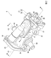
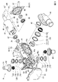
図2は、制御バルブ8の斜視図である。図3は、制御バルブ8の分解斜視図である。
図2、図3に示すように、制御バルブ8は、ケーシング21と、弁体22(図3参照)と、駆動ユニット23と、を主に備えている。
<Control valve>
2 is a perspective view of the
As shown in FIGS. 2 and 3, the
(ケーシング)
ケーシング21は、有底筒状のケーシング本体25と、ケーシング本体25の開口部を閉塞する蓋体26と、を有している。なお、以下の説明では、ケーシング21の軸線O1に沿う方向を単にケース軸方向という。ケース軸方向において、ケーシング本体25のケース周壁31に対してケーシング本体25の底壁部32に向かう方向を第1側といい、ケーシング本体25のケース周壁31に対して蓋体26に向かう方向を第2側という。さらに、軸線O1に直交する方向をケース径方向といい、軸線O1回りの方向をケース周方向という。
(casing)
The
ケーシング本体25のケース周壁31には、複数の取付片33が形成されている。各取付片33は、ケース周壁31からケース径方向の外側に突設されている。制御バルブ8は、例えば各取付片33を介してエンジンルーム内に固定される。なお、各取付片33の位置や数等は、適宜変更が可能である。
A plurality of mounting
図4は、図2のIV-IV線に沿う断面図である。
図3、図4に示すように、ケース周壁31における第2側に位置する部分には、ケース径方向の外側に膨出する流入ポート37が形成されている。流入ポート37には、流入ポート37をケース径方向に貫通する流入口37a(図4参照)が形成されている。流入口37aは、ケーシング21内外を連通している。流入ポート37の開口端面(ケース径方向の外側端面)には、上述したメイン流路10(図1参照)が接続される。
FIG. 4 is a cross-sectional view taken along line IV-IV of FIG.
As shown in FIGS. 3 and 4, a portion of the case
図4に示すように、ケース周壁31において、軸線O1を間に挟んで流入ポート37にケース径方向で対向する位置には、ケース径方向の外側に膨出するラジエータポート41が形成されている。ラジエータポート41には、フェール開口41a及びラジエータ流出口41b(流出口)がケース軸方向に並んで形成されている。フェール開口41a及びラジエータ流出口41bは、ラジエータポート41をそれぞれケース径方向に貫通している。本実施形態において、フェール開口41aは、上述した流入口37aにケース径方向で対向している。また、ラジエータ流出口41bは、フェール開口41aに対してケース軸方向の第1側に位置している。
As shown in FIG. 4, in the case
ラジエータポート41の開口端面(ケース径方向の外側端面)には、ラジエータジョイント42が接続されている。ラジエータジョイント42は、ラジエータポート41とラジエータ流路11(図1参照)の上流端部との間を接続している。なお、ラジエータジョイント42は、ラジエータポート41の開口端面に溶着(例えば、振動溶着等)されている。
A radiator joint 42 is connected to the opening end face of the radiator port 41 (the outer end face in the radial direction of the case). The radiator joint 42 connects between the
フェール開口41aには、サーモスタット45が設けられている。サーモスタット45は、上述した流入口37aにケース径方向で対向している。サーモスタット45は、ケーシング21内を流れる冷却水の温度に応じてフェール開口41aを開閉する。
A
蓋体26のうち、軸線O1に対してケース径方向でラジエータポート41寄りに位置する部分には、EGR流出口51が形成されている。EGR流出口51は、蓋体26をケース軸方向に貫通している。本実施形態において、EGR流出口51は、フェール開口41aの開口方向(ケース径方向)に交差(直交)している。また、EGR流出口51は、ケース軸方向から見た正面視において、サーモスタット45に少なくとも一部が重なり合っている。
An
蓋体26において、EGR流出口51の開口縁には、EGRジョイント52が形成されている。EGRジョイント52は、ケース軸方向の第2側に向かうに従いケース径方向の外側に延びる管状に形成され、EGR流出口51と上述したEGR流路14(図1参照)の上流端部との間を接続している。
An EGR joint 52 is formed at the opening edge of the
図3に示すように、ケース周壁31において、ラジエータポート41よりもケース軸方向の第1側に位置する部分には、ケース径方向の外側に膨出する暖機ポート56が形成されている。暖機ポート56には、暖機ポート56をケース径方向に貫通する暖機流出口56a(流出口)が形成されている。暖機ポート56の開口端面には、暖機ジョイント62が接続されている。暖機ジョイント62は、暖機ポート56と上述した暖機流路12(図1参照)の上流端部とを接続している。なお、暖機ジョイント62は、暖機ポート56の開口端面に溶着(例えば、振動溶着等)されている。
As shown in FIG. 3 , a warm-up
図2,図3に示すように、ケース周壁31のうち、ケース軸方向におけるラジエータポート41と暖機ポート56との間であって、かつ暖機ポート56に対してケース周方向で180°程度ずれた位置には、空調ポート66が形成されている。空調ポート66には、空調ポート66をケース径方向に貫通する空調流出口66a(流出口)が形成されている。空調ポート66の開口端面には、空調ジョイント68が接続されている。空調ジョイント68は、空調ポート66と上述した空調流路13(図1参照)の上流端部とを接続している。なお、空調ジョイント68は、空調ポート66の開口端面に溶着(例えば、振動溶着等)されている。
As shown in FIGS. 2 and 3, in the case
(駆動ユニット)
図2に示すように、駆動ユニット23は、ケーシング本体25の底壁部32に取り付けられている。駆動ユニット23は、図示しないモータや減速機構、制御基板等がユニットケース内に収納されている。
(drive unit)
As shown in FIG. 2 , the
(ロータ)
図3、図4に示すように、弁体22は、ケーシング21内に収容されている。弁体22は、円筒状に形成され、ケーシング21の内部において、ケーシング21の軸線O1と同軸に配置されている。弁体22は、軸線O1回りに回転することで、上述した各流出口(ラジエータ流出口41b、暖機流出口56a及び空調流出口66a)を開閉する。
(rotor)
As shown in FIGS. 3 and 4, the
図4に示すように、弁体22は、ロータ本体72の内側に内側軸部73がインサート成形されて構成されている。内側軸部73は、軸線O1と同軸に延在している。
As shown in FIG. 4 , the
内側軸部73の第1側端部は、底壁部32に形成された貫通孔(大気開放部)32aを通して底壁部32をケース軸方向に貫通している。内側軸部73の第1側端部は、上述した底壁部32に設けられた第1ブッシュ(第1軸受)78に回転可能に支持されている。具体的に、底壁部32には、ケース軸方向の第2側に向けて第1軸収容壁79が形成されている。第1軸収容壁79は、上述した貫通孔32aを取り囲んでいる。第1軸収容壁79の内側には、上述した第1ブッシュ78が嵌合されている。
A first side end portion of the
内側軸部73のうち、第1ブッシュ78よりもケース軸方向の第1側に位置する部分(底壁部32よりも外側に位置する部分)には、連結部73aが形成されている。連結部73aは、ケーシング21の外部において、上述した駆動ユニット23に連結されている。これにより、駆動ユニット23の動力が内側軸部73に伝達される。
A connecting
内側軸部73の第2側端部は、上述した蓋体26に設けられた第2ブッシュ(第2軸受)84に回転可能に支持されている。具体的に、蓋体26には、ケース軸方向の第1側に向けて第2軸収容壁86が形成されている。第2軸収容壁86は、上述したEGR流出口51よりもケース径方向の内側で、軸線O1を取り囲んでいる。第2軸収容壁86の内側には、上述した第2ブッシュ84が嵌合されている。
A second side end portion of the
ロータ本体72は、上述した内側軸部73の周囲を取り囲んでいる。ロータ本体72は、内側軸部73を覆う外側軸部81と、外側軸部81を囲繞する周壁部82と、外側軸部81と周壁部82を連結するスポーク部83と、を有している。
The
外側軸部81は、内側軸部73におけるケース軸方向の両端部を露出させた状態で、内側軸部73の周囲を全周に亘って取り囲んでいる。本実施形態では、外側軸部81及び内側軸部73によって弁体22の回転軸85を構成している。
The
上述した第1軸収容壁79内において、第1ブッシュ78に対してケース軸方向の第2側に位置する部分には、第1リップシール87が設けられている。第1リップシール87は、第1軸収容壁79の内周面と回転軸85(外側軸部81)の外周面との間をシールする。第1軸収容壁79内において、第1リップシール87よりもケース軸方向の第1側に位置する部分は、貫通孔32aを通じて大気に開放されている。
A
一方、上述した第2軸収容壁86内において、第2ブッシュ84に対してケース軸方向の第1側に位置する部分には、第2リップシール88が設けられている。第2リップシール88は、第2軸収容壁86の内周面と回転軸85(外側軸部81)の外周面との間をシールする。蓋体26には、蓋体26をケース軸方向に貫通する貫通孔(大気開放部)98が形成されている。
On the other hand, a
弁体22の周壁部82は、軸線O1と同軸に配置されている。周壁部82は、ケーシング21内において、流入口37aよりもケース軸方向の第1側に位置する部分に配置されている。具体的に、周壁部82は、ケース軸方向において、フェール開口41aを回避し、かつラジエータ流出口41b、暖機流出口56a及び空調流出口66aに跨る位置に配置されている。周壁部82の内側は、流入口37aを通してケーシング21内に流入した冷却水がケース軸方向に流通する流通路91を構成している。一方、ケーシング21内において、周壁部82よりもケース軸方向の第2側に位置する部分は、流通路91に連通する接続流路92を構成している。なお、周壁部82の外周面と、ケース周壁31の内周面と、の間には、ケース径方向に隙間C2が設けられている。
A
周壁部82において、上述したラジエータ流出口41bとケース軸方向の同位置には、周壁部82をケース径方向に貫通する弁孔95が形成されている。弁孔95は、ケース径方向から見てラジエータ流出口41bに挿入されたシール筒部材131と少なくとも一部が重なり合う場合に、弁孔95を通じて周壁部82内(流通路91)とラジエータ流出口41bとを連通させる。
A
周壁部82において、上述した暖機流出口56aとケース軸方向の同位置には、周壁部82をケース径方向に貫通する別の弁孔96が形成されている。弁孔96は、ケース径方向から見て暖機流出口56aに挿入されたシール筒部材131と少なくとも一部が重なり合う場合に、弁孔96を通じて周壁部82内(流通路91)と暖機流出口56aとを連通させる。
In the
周壁部82において、上述した空調流出口66aとケース軸方向の同位置には、周壁部82をケース径方向に貫通するさらに別の弁孔97が形成されている。弁孔97は、ケース径方向から見て空調流出口66aに挿入されたシール筒部材131と少なくとも一部が重なり合う場合に、弁孔97を通じて周壁部82内(流通路91)と空調流出口66aとを連通させる。
In the
弁体22は、軸線O1回りの回転に伴い、弁孔95,96,97と、これらに対応する各流出口41b,56a,66aとの連通及び遮断を切り替える。なお、弁孔95,96,97と流出口41b,56a,66aの連通パターンは、適宜設定が可能である。
As the
つづいて、暖機ポート56及び暖機ジョイント62の接続部分の詳細について説明する。なお、ラジエータポート41とラジエータジョイント42との接続部分、及び空調ポート66と空調ジョイント68との接続部分については、暖機ポート56及び暖機ジョイント62の接続部分と同等の構成であるため、説明を省略する。
Next, the details of the connection between the warm-up
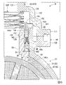
図5は、図2のV―V線に相当する拡大断面図である。以下の説明では、暖機流出口56aの軸線O2に沿う方向をポート軸方向(第1方向)という場合がある。この場合、ポート軸方向において、暖機ポート56に対して軸線O1に向かう方向を内側といい、暖機ポート56に対して軸線O1から離間する方向を外側という。また、軸線O2に直交する方向をポート径方向(第2方向)といい、軸線O2回りの方向をポート周方向という場合がある。
図5に示すように、暖機ポート56は、ポート軸方向に延びるシール筒部101と、シール筒部101からポート径方向の外側に張り出すポートフランジ部102と、を有している。シール筒部101の内側は、上述した暖機流出口56a(流出口)を構成している。本実施形態において、シール筒部101の内径は、ポート軸方向の外側端部を除く領域で一様に設定されている。
FIG. 5 is an enlarged cross-sectional view corresponding to line VV in FIG. In the following description, the direction along the axis O2 of the warm-up
As shown in FIG. 5, the warm-up
ポートフランジ部102の外周部分には、ポート軸方向の外側に突出する囲繞壁105が形成されている。囲繞壁105は、ポートフランジ部102の全周に亘って形成されている。ポートフランジ部102において、囲繞壁105に対してポート径方向の内側に位置する部分には、ポート軸方向の外側に突出するポート接合部106が形成されている。ポート接合部106は、ポートフランジ部102の全周に亘って形成されている。
A surrounding
暖機ジョイント62は、軸線O2と同軸に配置されたジョイント筒部110と、ジョイント筒部110におけるポート軸方向の内側端部からポート径方向の外側に張り出すジョイントフランジ部111と、を有している。
The warm-up joint 62 has a joint
ジョイントフランジ部111は、外径がポートフランジ部102と同等で、かつ内径がシール筒部101の外径よりも大きい環状に形成されている。ジョイントフランジ部111の内周部分には、ポート軸方向の内側に突出するジョイント接合部113が形成されている。ジョイント接合部113は、ポート接合部106にポート軸方向で対向している。暖機ポート56及び暖機ジョイント62は、ポート接合部106とジョイント接合部113との対向面同士が振動溶着されることで、互いに接合されている。
The
ジョイント筒部110は、ジョイントフランジ部111の内周縁からポート軸方向の外側に延在している。ジョイント筒部110は、ポート軸方向の外側に向かうに従い段階的に縮径する多段筒状に形成されている。具体的には、ジョイント筒部110は、大径部121、中径部122及び小径部123がポート軸方向の外側に向けて順に連なっている。
The joint
大径部121は、上述したシール筒部101に対してポート径方向の外側に間隔をあけた状態で、シール筒部101を囲繞している。中径部122は、シール筒部101に対してポート軸方向に隙間Q1をあけて対向している。
The large-
暖機ポート56及び暖機ジョイント62で囲まれた部分には、シール機構130が設けられている。シール機構130は、シール筒部材131と、付勢部材132と、シールリング133と、ホルダ134と、を有している。なお、図3に示すように、上述したラジエータポート41内及び空調ポート66内にも、暖機ポート56内に設けられたシール機構130と同様の構成からなるシール機構130が設けられている。本実施形態の説明では、ラジエータポート41内及び空調ポート66内に設けられたシール機構130については、暖機ポート56内に設けられたシール機構130と同様の符号を付して説明を省略する。
A
図5に示すように、シール筒部材131は、暖機流出口56a内に挿入されている。シール筒部材131は、軸線O2と同軸に延びる周壁を有している。シール筒部材131の周壁は、ポート軸方向の外側に向かうに従い外径が段状に縮径する多段筒状に形成されている。具体的には、シール筒部材131の周壁は、ポート軸方向の外側(軸方向の一端側)に位置され、暖機流出口56aの下流側に連通する第1筒部142と、ポート軸方向の内側(軸方向の他端側)に位置され、第1筒部142よりも内径及び外径が大きい第2筒部141と、を有している。
As shown in FIG. 5, the
シール筒部材131は、大径の第2筒部141がシール筒部101の内周面に摺動可能に挿入されている。第2筒部141におけるポート軸方向の内側端面は、弁体22の周壁部82の外周面に摺動自在に当接する弁摺接面141aを構成している。なお、本実施形態において、弁摺接面141aは、周壁部82の外周面の曲率半径に倣って形成された湾曲面とされている。
The
第1筒部142の外周面は、第2筒部141の外周面に対して段差面143を介して連なっている。段差面143は、ポート軸方向の内側に向かうに従いポート径方向の外側に傾斜した後、ポート径方向の外側にさらに延設されている。したがって、小径の第1筒部142の外周面と、シール筒部101の内周面と、の間には、ポート径方向にシール隙間Q2が設けられている。
The outer peripheral surface of the first
第1筒部142におけるポート軸方向の外側端面(以下、「座面142a」という。)は、ポート軸方向と直交する平坦面とされている。第1筒部142の座面142aは、ポート軸方向においてシール筒部101の外側端面と同等の位置に配置されている。なお、シール筒部材131は、暖機ジョイント62に対してポート径方向及びポート軸方向で離間している。
An outer end surface of the first
付勢部材132は、シール筒部材131の座面142aと、暖機ジョイント62における小径部123のポート軸方向の内側端面と、の間に介在している。付勢部材132は、例えばウェーブスプリングである。付勢部材132は、シール筒部材131をポート軸方向の内側に向けて(周壁部82に向けて)付勢している。
The biasing
シールリング133は、例えばYパッキンである。シールリング133は、開口部(二股部)をポート軸方向の内側に向けた状態で、シール筒部材131の第1筒部142に外挿されている。具体的に、シールリング133は、上述したシール隙間Q2内に配置された状態で、二股部の各先端部が第1筒部142の外周面及びシール筒部101の内周面にそれぞれ摺動可能に密接している。なお、シール隙間Q2内において、シールリング133に対してポート軸方向の内側領域は、シール筒部101の内周面とシール筒部材131の第2筒部141との隙間を通じてケーシング21の液圧が導入される。段差面143は、ポート軸方向におけるシール筒部材131の弁摺接面141aと相反する向きに形成されている。段差面143は、ケーシング21内の冷却水の液圧を受けてポート軸方向の内側に押圧される受圧面を構成している。
The
図6は、図5のVI部拡大図である。
ここで、シール筒部材131において、段差面143の面積S1と、弁摺接面141aの面積S2とは、以下の式(1),(2)を満たすように設定されている。
S1<S2≦S1/k …(1)
α≦k<1 …(2)
k:弁摺接面141aと弁体22の周壁部82との間の微少隙間を流れる冷却水の圧力減少定数
α:冷却水の物性によって決まる圧力減少定数の下限値
なお、段差面143の面積S1と弁摺接面141aの面積S2は、ポート軸方向に投影したときの面積を意味する。
FIG. 6 is an enlarged view of the VI part of FIG.
Here, in the
S1<S2≦S1/k (1)
α≦k<1 (2)
k: pressure reduction constant of the cooling water flowing through the minute gap between the valve sliding
式(2)におけるαは、冷却水の種類や、使用環境(例えば、温度)等によって決まる圧力減少定数の標準値である。例えば、通常使用条件下において、水の場合にはα=1/2となる。使用する冷却水の物性が変化した場合には、α=1/3等に変化する。
また、式(2)における圧力減少定数kは、弁摺接面141aがポート径方向の外側端縁から内側端縁にかけて均一に周壁部82に接しているときには、圧力減少定数の標準値であるα(例えば、1/2)となる。但し、シール筒部材131の製造誤差や組付け誤差等によって、弁摺接面141aの外周部分と周壁部82との間の隙間が弁摺接面141aの内周部分に対して僅かに増大することがある。この場合、式(2)における圧力減少定数kは、次第にk=1に近づくことになる。
α in equation (2) is a standard value of the pressure reduction constant determined by the type of cooling water, the usage environment (for example, temperature), and the like. For example, under normal use conditions, α=1/2 for water. When the physical properties of the cooling water used change, α changes to 1/3 or the like.
The pressure reduction constant k in equation (2) is a standard value of the pressure reduction constant when the valve sliding
本実施形態では、シール筒部材131の弁摺接面141aと周壁部82の外周面との間に、摺動を許容するために微小な隙間があることを前提として、段差面143と弁摺接面141aの各面積S1,S2の関係が式(1),(2)によって決められている。
すなわち、シール筒部材131の段差面143には、上述したようにケーシング21内の冷却水の圧力がそのまま作用する。一方で、弁摺接面141aには、ケーシング21内の冷却水の圧力がそのまま作用しない。具体的に、冷却水の圧力は、弁摺接面141aと周壁部82の間の微小な隙間を冷却水がポート径方向の外側端縁から内側端縁に向かって流れるときに圧力減少を伴いつつ作用する。このとき、冷却水の圧力は、ポート径方向の内側に向かって漸減しつつ、シール筒部材131をポート軸方向の外側に押し上げようとする。
In this embodiment, it is assumed that there is a minute gap between the valve sliding
That is, the pressure of the cooling water in the
その結果、シール筒部材131の段差面143には、段差面143の面積S1にケーシング21内の圧力Pを乗じた力がそのまま作用する。一方、シール筒部材131の弁摺接面141aには、弁摺接面141aの面積S2にケーシング21内の圧力Pと圧力減少定数kとを乗じた力が作用する。
As a result, a force obtained by multiplying the area S1 of the stepped
本実施形態の制御バルブ8は、式(1)からも明らかなようにk×S2≦S1が成り立つように面積S1,S2が設定されている。このため、P×k×S2≦P×S1の関係も成り立つ。
したがって、シール筒部材131の段差面143に作用する押し付け方向の力F1(F1=P×S1)は、シール筒部材131の弁摺接面141aに作用する浮き上がり方向の力F2(F2=P×k×S2)以上に大きくなる。よって、本実施形態の制御バルブ8においては、ケーシング21内の冷却水の圧力の関係のみによっても、シール筒部材131と周壁部82との間をシールすることができる。
The areas S1 and S2 of the
Therefore, the force F1 (F1=P×S1) in the pressing direction acting on the stepped
一方、本実施形態では、上述したようにシール筒部材131の段差面143の面積S1が弁摺接面141aの面積S2よりも小さい。そのため、ケーシング21内の冷却水の圧力が大きくなっても、シール筒部材131の弁摺接面141aが過剰な力で周壁部82に押し付けられるのを抑制できる。したがって、本実施形態の制御バルブ8を採用した場合には、弁体22を回転駆動する駆動ユニット23の大型化及び高出力化を回避することができる上、シール筒部材131や各ブッシュ78,84(図4参照)の早期摩耗を抑制できる。
On the other hand, in this embodiment, as described above, the area S1 of the stepped
このように、本実施形態では、シール筒部材131に作用するポート軸方向の内側への押し付け力が、シール筒部材131に作用するポート軸方向の外側への浮き上がり力を下回らない範囲で、弁摺接面141aの面積S2が段差面143の面積S1よりも大きく設定されている。そのため、周壁部82に対するシール筒部材131の過剰な力での押し付けを抑制しつつ、シール筒部材131と周壁部82との間をシールできる。
As described above, in the present embodiment, the pressure force acting on the
上述したホルダ134は、隙間Q1内において、暖機ポート56及び暖機ジョイント62に対してポート軸方向に移動可能に構成されている。また、ホルダ134は、暖機ポート56及び暖機ジョイント62の少なくとも何れかにポート軸方向で離間可能に配置されている。ホルダ134は、ホルダ筒部151と、ホルダフランジ部152と、規制部153と、を有している。
The
ホルダ筒部151は、ポート軸方向に延在している。ホルダ筒部151は、シール隙間Q2内にポート軸方向の外側から挿入されている。ホルダ筒部151におけるポート軸方向の内側端面には、上述したシールリング133の底部が当接可能とされている。すなわち、ホルダ筒部151は、シールリング133のポート軸方向の外側への移動を規制する。
The
ホルダフランジ部152は、ホルダ筒部151におけるポート軸方向の外側端部からポート径方向の外側に突設されている。ホルダフランジ部152は、シール筒部101におけるポート軸方向の外側端面と、中径部122におけるポート軸方向の内側端面と、の間の隙間Q1に配置されている。ホルダ134のポート軸方向の内側への移動は、シール筒部101によって規制され、ホルダ134のポート軸方向の外側への移動は、中径部122によって規制される。
The
規制部153は、ホルダ筒部151の内周部分からポート軸方向の外側に筒状に突出して形成されている。規制部153は、付勢部材132のポート径方向の移動を、ホルダ筒部151とともに規制する。
The restricting
[シール筒部材の詳細]
図7は、シール筒部材131を弁摺接面141aの側を上にして見た斜視図である。また、図8は、シール筒部材131を弁摺接面141aの側から見た端面図である。なお、図8には、弁体22の周壁部82の弁孔96(95,57)が仮想線で示されている。
シール筒部材131は、第1筒部142と、第1筒部142よりも外径の大きい第2筒部141と、を有し、第2筒部141の軸方向の端部(軸方向の他端部)に、弁体22の周壁部82の外周面に摺動自在に当接する弁摺接面141aが設けられている。第1筒部142の外周面と第2筒部141の外周面の間には、段差面143が設けられている。また、第1筒部142の内径は、第2筒部141の内径よりも小さく形成されている。第1筒部142の内周面と第2筒部141の内周面の間には段差面44が設けられている。
[Details of seal tube member]
FIG. 7 is a perspective view of the
The
第2筒部141の軸方向の端部(ポート軸方向の内側)の周壁は、弁体22の周壁部82の外周面の形状に沿って、周壁部82に向かう方向の突出高さが周方向で連続的に変化している。つまり、第2筒部141の軸方向の端部の周壁は、弁摺接面141aが弁体22の周壁部82の外周面に面接触するように、突出高さが連続して変化している。第2筒部141の軸方向の端部は、軸線O1(弁体22の回転軸線)に沿う方向に関して、最も外側に位置される領域の突出高さが最も低くなり、軸線O1と直交する方向(弁体22の回転方向に沿う方向)に関して、最も外側に位置される領域の突出高さが最も高くなっている。なお、図8中の符号C1は、弁体22の軸線O1方向においての弁孔96(95,97)の中心を示す中心線である。
The peripheral wall of the axial end (inner side in the port axial direction) of the second
シール筒部材131は、第2筒部141の周壁のうちの、弁体22の周壁部82に向かう方向の突出高さ(以下、「弁体22方向の突出高さ」と呼ぶ。)の高い二つの領域(弁体22方向の突出高さが最大となる部位を含む二つの領域)に肉厚部55が設けられている。各肉厚部55は、第2筒部141の内周部に径方向内側に膨出して設けられている。二位置に配置された肉厚部55は、図8に示すように、シール筒部材131を軸方向(ポート軸方向)から見たときに、相互に平行になるように形成されている。第2筒部141の径方向内側には、相互に対向する直線状の内縁部が肉厚部55によって形成されている。本実施形態の場合、第2筒部141の端部の突出高さの最も高い部位に肉厚部55の最も肉厚の厚い部分が配置されている。
なお、肉厚部55は、第1筒部142の内径よりも径方向内側に突出しないように形成することが望ましい。
The
It is desirable that the
また、肉厚部55は、第2筒部141の内周面に径方向内側に膨出して形成されているが、肉厚部55は、第1筒部142と第2筒部141の間の段差面44部分から、第2筒部141の弁摺接面141a(シール筒部材131の軸方向の他端部の端面)に達しない領域に延在している。第2筒部141の弁体22側の端面に形成される弁摺接面141aは、シール筒部材131の円周方向の全域に亘って略一定の径方向幅に形成されている。
The
[制御バルブの動作方法]
次に、上述した制御バルブ8の動作方法を説明する。
図1に示すように、メイン流路10において、ウォータポンプ3により送出される冷却水は、エンジン2で熱交換された後、制御バルブ8に向けて流通する。図4に示すように、メイン流路10においてエンジン2を通過した冷却水は、流入口37aを通してケーシング21内の接続流路92内に流入する。
[How the control valve operates]
Next, a method of operating the above-described
As shown in FIG. 1 , in the
接続流路92内に流入した冷却水のうち、一部の冷却水はEGR流出口51内に流入する。EGR流出口51内に流入した冷却水は、EGRジョイント52を通ってEGR流路14内に供給される。EGR流路14内に供給された冷却水は、EGRクーラ7において、冷却水とEGRガスとの熱交換が行われた後、メイン流路10に戻される。
A portion of the cooling water that has flowed into the
一方、接続流路92内に流入した冷却水のうち、EGR流出口51内に流入しなかった冷却水は、ケース軸方向の第2側から流通路91内に流入する。流通路91内に流入した冷却水は、流通路91内をケース軸方向に流通する過程で各流出口に分配される。すなわち、流通路91内に流入する冷却水は、各流出口のうち対応する弁孔に連通している流出口を通して各流路11~13に分配される。
On the other hand, of the cooling water that has flowed into the connecting
制御バルブ8において、弁孔と流出口との連通パターンを切り替えるには、弁体22を軸線O1回りに回転させる。そして、設定したい連通パターンに対応する位置で弁体22の回転を停止させることで、弁体22の停止位置に応じた連通パターンで弁孔と流出口とが連通する。
In order to switch the communication pattern between the valve hole and the outflow port in the
以上のように、本実施形態の制御バルブ8は、シール筒部材131の軸方向の端部の周壁のうちの、弁体22方向の突出高さの高い領域に、他の部位に比較して肉厚の厚い肉厚部55が設けられている。このため、シール筒部材131の軸方向の端部の周壁のうちの、ケーシング21内の冷却液の液圧を受けて撓み変形し易い領域が肉厚部55によって補強される。この結果、シール筒部材131の軸方向の端部の突出高さの変化に起因するシール筒部材131の周域での撓みのばらつきを少なくすることが可能になる。よって、本実施形態の制御バルブ8を採用した場合には、シール筒部材131と弁体22の間のシール性能を高めることができる。
As described above, in the
特に、本実施形態の制御バルブ8では、シール筒部材131の周壁の径方向内側に、肉厚部55が膨出して設けられている。このため、シール筒部材131の径方向外側から作用するケーシング21内の冷却水の圧力をシール筒部材131の径方向内側から効率良く受け止めることができる。したがって、本実施形態の構成を採用した場合には、シール筒部材131の弁体22側の端部の撓み変形をより効率良く抑制することができる。
In particular, in the
また、本実施形態の制御バルブ8は、シール筒部材131の軸方向の端面に達しない領域に肉厚部55が設けられ、シール筒部材131の軸方向の端面の弁摺接面141aが、シール筒部材131の円周方向の全域に亘って略一定の径方向幅に形成されている。このため、シール筒部材131の周方向での撓みのばらつきを肉厚部55によって少なくしつつ、弁摺接面141aの周方向での面圧のばらつきも少なくすることができる。よって、本実施形態の構成を採用した場合には、シール筒部材131の弁摺接面141aと弁体22の周壁部82との間のシール性能をより高めることができる。
In addition, the
さらに、本実施形態の制御バルブ8は、ケーシング21の流出口に連通する第1筒部142と、弁摺接面141aを有する第2筒部141がシール筒部材131に設けられ、第1筒部142の内径が第2筒部141の内径よりも小さく形成され、肉厚部55が第2筒部141の径方向内側に設けられている。このため、シール筒部材131を通して流出口の下流側に流出する冷却水の流量が第1筒部142の内径によって決定され、内径の大きい第2筒部141に設けられる肉厚部55は、流出口から流出する冷却水の流量に影響を与えなくなる。したがって、本実施形態の構成を採用した場合には、流出口から流出する液体の流量を容易に設定調整することができる。
Further, in the
[他の実施形態]
図9は、他の実施形態のシール筒部材131Aを用いた場合の上記の実施形態の図5と同様の拡大図である。図10は、シール筒部材131Aを弁摺接面141Aaの側を上にして見た斜視図であり、図11は、シール筒部材131Aを弁摺接面141Aaの側から見た端面図である。なお、図11には、開弁(連通)開始時と開弁(連通)終了時における弁孔96(95,97)が仮想線で示されている。
シール筒部材131Aは、上記の実施形態と同様に、第1筒部142と、第1筒部142よりも内径及び外径の大きい第2筒部141と、を有し、第2筒部141の軸方向の端部(軸方向の他端部)に、弁体22の周壁部82の外周面に摺動自在に当接する弁摺接面141Aaが設けられている。第2筒部141の軸方向の端部(ポート軸方向の内側)の周壁は、弁体22の周壁部82の外周面の形状に沿って、周壁部82に向かう方向の突出高さが周方向で連続的に変化している。
[Other embodiments]
FIG. 9 is an enlarged view similar to FIG. 5 of the above embodiment when using a
131 A of sealing cylinder members have the
本実施形態のシール筒部材131Aは、上記の実施形態と同様に、第2筒部141の周壁のうちの、弁体22方向の突出高さの高い二つの領域(弁体22方向の突出高さが最大となる部位を含む二つの領域)に、第2筒部141の内周部から径方向内側に膨出して肉厚部55Aが設けられている。ただし、肉厚部55Aは、第1筒部142と第2筒部141の間の段差面44部分から、第2筒部141の弁体22側の端面(シール筒部材131の軸方向の他端部の端面)まで延在している。本実施形態では、各肉厚部55Aの軸方向の端面が弁摺接面141Aaの一部を構成している。
As in the above-described embodiment, the
本実施形態の場合も、第2筒部141の周壁上の二位置に配置された肉厚部55Aは、図11に示すように、シール筒部材131Aを軸方向(ポート軸方向)から見たときに、相互に平行になるように形成されている。弁摺接面141Aaの円周方向上の二位置には、肉厚部55Aにより、軸線O1(弁体22の回転軸線)と平行に延びる一対の直線状内縁部50が形成されている。一対の直線状内縁部50は、弁体22の回転に伴う弁孔96(95,97)の旋回変位時に、開弁の開始(弁孔96(95,97)とシール筒部材131Aの連通開始)と開弁の終了(弁孔96(95,97)とシール筒部材131Aの連通終了)とを担う。このとき、直線状内縁部50は、弁体22の回転方向に対し、直角に交差する姿勢において弁孔96(95,97)を開閉する。
In the case of this embodiment as well, the
本実施形態の制御バルブ8Aは、シール筒部材131Aの肉厚部55Aが弁摺接面141Aaまで延在して一対の直線状内縁部50を構成する点以外は上記の実施形態と同様の構成とされている。このため、本実施形態の制御バルブ8Aは、上記の実施形態とほぼ同様の基本的な効果を得ることができる。
The
ただし、本実施形態の制御バルブ8Aは、弁孔96(95,97)の連通開始位置と連通終了位置を直線状内縁部50によって一定に維持できる、という特有の効果を得ることができる。すなわち、本実施形態では、シール筒部材131Aの肉厚部55Aが弁摺接面141Aaまで延在して、弁体22の軸線O1と平行に延びる一対の直線状内縁部50を構成しているため、常に弁体22の一定の回転位置において、弁孔96(95,97)とシール筒部材131Aを連通させ、さらに両者を非連通にすることができる。したがって、本実施形態の制御バルブ8Aを採用した場合には、冷却水の流出特性をより安定させることができる。
However, the
なお、本発明は上記の実施形態に限定されるものではなく、その要旨を逸脱しない範囲で種々の設計変更が可能である。 The present invention is not limited to the above-described embodiments, and various design changes are possible without departing from the gist of the present invention.
8,8A…制御バルブ
21…ケーシング
22…弁体
37a…流入口
41b…ラジエータ流出口(流出口)
50…直線状内縁部
55,55A…肉厚部
56a…暖気流出口(流出口)
66a…空調流出口(流出口)
82…周壁部
95,96,97…弁孔
131,131A…シール筒部材
141…第2筒部
141a,141Aa…弁摺接面
142…第1筒部
O1…軸線(回転軸線)
8, 8A...
50... Linear
66a ... Air conditioning outlet (outlet)
82...
Claims (4)
前記ケーシングの内部に回転可能に配置され、内外を連通する弁孔が形成された周壁部を有する弁体と、
軸方向の一端部が、前記流出口の下流側に連通するとともに、軸方向の他端部に、前記弁体の前記弁孔の回転経路と少なくとも一部がラップする位置で前記周壁部の外周面に摺動自在に当接する弁摺接面が設けられたシール筒部材と、を備え、
前記シール筒部材の軸方向の他端部は、前記周壁部の外周面の形状に沿って、前記周壁部に向かう方向の突出高さが周方向で連続的に変化する制御バルブにおいて、
前記シール筒部材の軸方向の他端部のうちの、前記突出高さの高い領域には、他の部位に比較して肉厚の厚い肉厚部が設けられ、
前記肉厚部は、前記シール筒部材の周壁の径方向内側に膨出して設けられていることを特徴とする制御バルブ。 a casing having an inlet through which liquid flows from the outside and an outlet through which the liquid that has flowed inside flows out to the outside;
a valve element rotatably disposed inside the casing and having a peripheral wall portion formed with a valve hole communicating between the inside and the outside;
One end in the axial direction communicates with the downstream side of the outflow port, and the other end in the axial direction is provided with an outer periphery of the peripheral wall portion at a position where at least a part of the rotation path of the valve hole of the valve body overlaps. a seal cylinder member provided with a valve sliding contact surface that slidably contacts the surface,
In a control valve in which the other axial end portion of the seal cylinder member protrudes continuously in the circumferential direction along the shape of the outer peripheral surface of the peripheral wall portion in the direction toward the peripheral wall portion,
A thick portion that is thicker than other portions is provided in a region of the other end portion in the axial direction of the seal cylinder member where the protruded height is high ,
The control valve , wherein the thick portion is provided so as to bulge radially inward of the peripheral wall of the seal cylinder member .
前記弁摺接面は、前記シール筒部材の円周方向の全域に亘って略一定の径方向幅に形成されている請求項1に記載の制御バルブ。 The thick portion is provided in a region that does not reach the end face of the other axial end portion of the seal cylinder member,
2. The control valve according to claim 1 , wherein the valve sliding contact surface is formed to have a substantially constant radial width over the entire circumference of the seal cylinder member.
前記弁摺接面のうちの、前記シール筒部材の周方向で相互に対向する二位置には、前記肉厚部により、前記弁体の回転軸線と平行に延びる直線状内縁部がそれぞれ形成されていることを特徴とする請求項1に記載の制御バルブ。 the thick portion extends to an end surface of the other end portion of the tubular seal member so as to constitute a part of the valve sliding contact surface;
Linear inner edge portions extending parallel to the rotation axis of the valve body are formed by the thick portion at two positions of the valve sliding contact surface that face each other in the circumferential direction of the seal cylinder member. 2. The control valve of claim 1 , wherein:
軸方向の一端側に位置され、前記流出口の下流側に連通する第1筒部と、
軸方向の他端側に位置され、軸方向の端部に前記弁摺接面が形成された第2筒部と、を有し、
前記第1筒部の内径は、前記第2筒部の内径よりも小さく形成され、
前記肉厚部は、前記第2筒部の径方向内側に設けられていることを特徴とする請求項1~3のいずれか1項に記載の制御バルブ。 The seal cylinder member is
a first cylindrical portion located on one end side in the axial direction and communicating with the downstream side of the outflow port;
a second tubular portion located on the other axial end side and having the valve sliding contact surface formed at the axial end thereof;
The inner diameter of the first cylindrical portion is formed smaller than the inner diameter of the second cylindrical portion,
The control valve according to any one of claims 1 to 3 , wherein the thick portion is provided radially inward of the second cylinder portion.
Priority Applications (4)
| Application Number | Priority Date | Filing Date | Title |
|---|---|---|---|
| JP2018171893A JP7146540B2 (en) | 2018-09-13 | 2018-09-13 | control valve |
| DE102019121311.8A DE102019121311A1 (en) | 2018-09-13 | 2019-08-07 | CONTROL VALVE |
| US16/547,138 US11105430B2 (en) | 2018-09-13 | 2019-08-21 | Control valve |
| CN201910858222.XA CN110894884A (en) | 2018-09-13 | 2019-09-11 | Control valve |
Applications Claiming Priority (1)
| Application Number | Priority Date | Filing Date | Title |
|---|---|---|---|
| JP2018171893A JP7146540B2 (en) | 2018-09-13 | 2018-09-13 | control valve |
Publications (2)
| Publication Number | Publication Date |
|---|---|
| JP2020041535A JP2020041535A (en) | 2020-03-19 |
| JP7146540B2 true JP7146540B2 (en) | 2022-10-04 |
Family
ID=69646645
Family Applications (1)
| Application Number | Title | Priority Date | Filing Date |
|---|---|---|---|
| JP2018171893A Active JP7146540B2 (en) | 2018-09-13 | 2018-09-13 | control valve |
Country Status (4)
| Country | Link |
|---|---|
| US (1) | US11105430B2 (en) |
| JP (1) | JP7146540B2 (en) |
| CN (1) | CN110894884A (en) |
| DE (1) | DE102019121311A1 (en) |
Families Citing this family (6)
| Publication number | Priority date | Publication date | Assignee | Title |
|---|---|---|---|---|
| DE112018001431T5 (en) * | 2017-03-17 | 2019-12-05 | Yamada Manufacturing Co., Ltd. | control valve |
| JP7344663B2 (en) * | 2019-03-27 | 2023-09-14 | 株式会社山田製作所 | control valve |
| JP7227050B2 (en) * | 2019-03-27 | 2023-02-21 | 株式会社山田製作所 | control valve |
| JP7287245B2 (en) * | 2019-11-12 | 2023-06-06 | 株式会社デンソー | control valve |
| US11226045B1 (en) * | 2019-11-22 | 2022-01-18 | United States Of America As Represented By The Administrator Of Nasa | Debris tolerant valve |
| JP7486872B2 (en) | 2020-10-15 | 2024-05-20 | 日立Astemo株式会社 | How to assemble a control valve |
Citations (2)
| Publication number | Priority date | Publication date | Assignee | Title |
|---|---|---|---|---|
| JP2013245738A (en) | 2012-05-24 | 2013-12-09 | Mikuni Corp | Rotary valve |
| JP2017003064A (en) | 2015-06-15 | 2017-01-05 | 日立オートモティブシステムズ株式会社 | Flow control valve |
Family Cites Families (18)
| Publication number | Priority date | Publication date | Assignee | Title |
|---|---|---|---|---|
| US2698731A (en) * | 1949-06-29 | 1955-01-04 | Gustave J Koehler | Fluid valve |
| US3382892A (en) * | 1965-03-08 | 1968-05-14 | Weatherhead Co | Quick-disconnect coupling |
| US4593918A (en) * | 1984-07-11 | 1986-06-10 | Alfred Geissler | Sealing arrangement |
| US4778148A (en) * | 1986-06-25 | 1988-10-18 | Volkswagen Ag | Sealing arrangement for a rotary slide valve |
| DE3720082A1 (en) * | 1986-06-25 | 1988-01-07 | Volkswagen Ag | Sealing arrangement for a rotary slide valve |
| US4911408A (en) * | 1989-01-03 | 1990-03-27 | Kemp Development Corporation | Seat assembly for ball valves |
| US6974121B2 (en) * | 2002-03-19 | 2005-12-13 | Fisher Controls International, Inc. | Fluid flow control valve with bi-directional shutoff |
| JP2013519828A (en) * | 2010-02-16 | 2013-05-30 | ピールブルグ パンプ テクノロジー ゲゼルシャフト ミット ベシュレンクテル ハフツング | Mechanical coolant pump |
| JP5806871B2 (en) * | 2011-07-27 | 2015-11-10 | 株式会社ケーヒン | Valve device |
| WO2014184783A1 (en) * | 2013-05-17 | 2014-11-20 | Magna Powertrain Inc. | Low-drag sealing method for thermal management valve |
| CN105090588B (en) * | 2014-05-21 | 2018-04-20 | 航天长征化学工程股份有限公司 | A kind of three-way diverter valve and its encapsulating method |
| JP6432433B2 (en) * | 2014-07-07 | 2018-12-05 | 株式会社デンソー | Valve device |
| KR101567434B1 (en) * | 2014-07-31 | 2015-11-12 | 인지컨트롤스 주식회사 | Fail safety coolant control valve |
| JP6380073B2 (en) * | 2014-12-12 | 2018-08-29 | アイシン精機株式会社 | Refrigerant control valve device |
| US10927972B2 (en) * | 2015-03-03 | 2021-02-23 | Hitachi Automotive Systems, Ltd. | Flow rate control valve |
| JP6409956B2 (en) * | 2015-03-30 | 2018-10-24 | アイシン精機株式会社 | Refrigerant control valve device |
| JP6668780B2 (en) * | 2016-01-26 | 2020-03-18 | アイシン精機株式会社 | Refrigerant control valve device |
| US10018281B2 (en) * | 2016-06-16 | 2018-07-10 | Vanguard International Semiconductor Corporation | Throttle valve |
-
2018
- 2018-09-13 JP JP2018171893A patent/JP7146540B2/en active Active
-
2019
- 2019-08-07 DE DE102019121311.8A patent/DE102019121311A1/en not_active Withdrawn
- 2019-08-21 US US16/547,138 patent/US11105430B2/en active Active
- 2019-09-11 CN CN201910858222.XA patent/CN110894884A/en active Pending
Patent Citations (2)
| Publication number | Priority date | Publication date | Assignee | Title |
|---|---|---|---|---|
| JP2013245738A (en) | 2012-05-24 | 2013-12-09 | Mikuni Corp | Rotary valve |
| JP2017003064A (en) | 2015-06-15 | 2017-01-05 | 日立オートモティブシステムズ株式会社 | Flow control valve |
Also Published As
| Publication number | Publication date |
|---|---|
| CN110894884A (en) | 2020-03-20 |
| US20200088308A1 (en) | 2020-03-19 |
| JP2020041535A (en) | 2020-03-19 |
| DE102019121311A1 (en) | 2020-03-19 |
| US11105430B2 (en) | 2021-08-31 |
Similar Documents
| Publication | Publication Date | Title |
|---|---|---|
| JP7146540B2 (en) | control valve | |
| JP7227050B2 (en) | control valve | |
| CN108005773B (en) | Control valve | |
| CN108005774B (en) | Control valve | |
| CN109139222B (en) | Control valve | |
| JP7344663B2 (en) | control valve | |
| JP7012566B2 (en) | Control valve | |
| CN110366654B (en) | Control valve | |
| JP7142150B2 (en) | control valve | |
| US20210291621A1 (en) | Control valve | |
| JP2020159514A (en) | Control valve | |
| JP7417446B2 (en) | control valve | |
| JP7409928B2 (en) | control valve | |
| JP7522569B2 (en) | Control valve | |
| US11703136B2 (en) | Control valve | |
| WO2024190096A1 (en) | Control valve | |
| JP2020051539A (en) | Control valve | |
| WO2023112600A1 (en) | Control valve | |
| WO2024190095A1 (en) | Control valve | |
| JP2024130126A (en) | Control valve | |
| JP2022146862A (en) | control valve | |
| JP2024130125A (en) | Control valve | |
| JP2021148239A (en) | Control valve | |
| JP2021152405A (en) | Control valve | |
| JP2023087314A (en) | control valve |
Legal Events
| Date | Code | Title | Description |
|---|---|---|---|
| A621 | Written request for application examination |
Free format text: JAPANESE INTERMEDIATE CODE: A621 Effective date: 20210611 |
|
| A977 | Report on retrieval |
Free format text: JAPANESE INTERMEDIATE CODE: A971007 Effective date: 20220523 |
|
| A131 | Notification of reasons for refusal |
Free format text: JAPANESE INTERMEDIATE CODE: A131 Effective date: 20220531 |
|
| A521 | Request for written amendment filed |
Free format text: JAPANESE INTERMEDIATE CODE: A523 Effective date: 20220726 |
|
| TRDD | Decision of grant or rejection written | ||
| A01 | Written decision to grant a patent or to grant a registration (utility model) |
Free format text: JAPANESE INTERMEDIATE CODE: A01 Effective date: 20220913 |
|
| A61 | First payment of annual fees (during grant procedure) |
Free format text: JAPANESE INTERMEDIATE CODE: A61 Effective date: 20220921 |
|
| R150 | Certificate of patent or registration of utility model |
Ref document number: 7146540 Country of ref document: JP Free format text: JAPANESE INTERMEDIATE CODE: R150 |