EP3428346A1 - Construction machine - Google Patents
Construction machine Download PDFInfo
- Publication number
- EP3428346A1 EP3428346A1 EP16893515.3A EP16893515A EP3428346A1 EP 3428346 A1 EP3428346 A1 EP 3428346A1 EP 16893515 A EP16893515 A EP 16893515A EP 3428346 A1 EP3428346 A1 EP 3428346A1
- Authority
- EP
- European Patent Office
- Prior art keywords
- engine
- reserve tank
- engine room
- cooling fan
- radiator
- Prior art date
- Legal status (The legal status is an assumption and is not a legal conclusion. Google has not performed a legal analysis and makes no representation as to the accuracy of the status listed.)
- Granted
Links
Images


Classifications
-
- E—FIXED CONSTRUCTIONS
- E02—HYDRAULIC ENGINEERING; FOUNDATIONS; SOIL SHIFTING
- E02F—DREDGING; SOIL-SHIFTING
- E02F9/00—Component parts of dredgers or soil-shifting machines, not restricted to one of the kinds covered by groups E02F3/00 - E02F7/00
- E02F9/08—Superstructures; Supports for superstructures
- E02F9/0858—Arrangement of component parts installed on superstructures not otherwise provided for, e.g. electric components, fenders, air-conditioning units
- E02F9/0866—Engine compartment, e.g. heat exchangers, exhaust filters, cooling devices, silencers, mufflers, position of hydraulic pumps in the engine compartment
-
- B—PERFORMING OPERATIONS; TRANSPORTING
- B60—VEHICLES IN GENERAL
- B60K—ARRANGEMENT OR MOUNTING OF PROPULSION UNITS OR OF TRANSMISSIONS IN VEHICLES; ARRANGEMENT OR MOUNTING OF PLURAL DIVERSE PRIME-MOVERS IN VEHICLES; AUXILIARY DRIVES FOR VEHICLES; INSTRUMENTATION OR DASHBOARDS FOR VEHICLES; ARRANGEMENTS IN CONNECTION WITH COOLING, AIR INTAKE, GAS EXHAUST OR FUEL SUPPLY OF PROPULSION UNITS IN VEHICLES
- B60K11/00—Arrangement in connection with cooling of propulsion units
- B60K11/02—Arrangement in connection with cooling of propulsion units with liquid cooling
- B60K11/04—Arrangement or mounting of radiators, radiator shutters, or radiator blinds
-
- B—PERFORMING OPERATIONS; TRANSPORTING
- B60—VEHICLES IN GENERAL
- B60K—ARRANGEMENT OR MOUNTING OF PROPULSION UNITS OR OF TRANSMISSIONS IN VEHICLES; ARRANGEMENT OR MOUNTING OF PLURAL DIVERSE PRIME-MOVERS IN VEHICLES; AUXILIARY DRIVES FOR VEHICLES; INSTRUMENTATION OR DASHBOARDS FOR VEHICLES; ARRANGEMENTS IN CONNECTION WITH COOLING, AIR INTAKE, GAS EXHAUST OR FUEL SUPPLY OF PROPULSION UNITS IN VEHICLES
- B60K11/00—Arrangement in connection with cooling of propulsion units
- B60K11/06—Arrangement in connection with cooling of propulsion units with air cooling
-
- B—PERFORMING OPERATIONS; TRANSPORTING
- B60—VEHICLES IN GENERAL
- B60K—ARRANGEMENT OR MOUNTING OF PROPULSION UNITS OR OF TRANSMISSIONS IN VEHICLES; ARRANGEMENT OR MOUNTING OF PLURAL DIVERSE PRIME-MOVERS IN VEHICLES; AUXILIARY DRIVES FOR VEHICLES; INSTRUMENTATION OR DASHBOARDS FOR VEHICLES; ARRANGEMENTS IN CONNECTION WITH COOLING, AIR INTAKE, GAS EXHAUST OR FUEL SUPPLY OF PROPULSION UNITS IN VEHICLES
- B60K11/00—Arrangement in connection with cooling of propulsion units
- B60K11/08—Air inlets for cooling; Shutters or blinds therefor
-
- B—PERFORMING OPERATIONS; TRANSPORTING
- B60—VEHICLES IN GENERAL
- B60K—ARRANGEMENT OR MOUNTING OF PROPULSION UNITS OR OF TRANSMISSIONS IN VEHICLES; ARRANGEMENT OR MOUNTING OF PLURAL DIVERSE PRIME-MOVERS IN VEHICLES; AUXILIARY DRIVES FOR VEHICLES; INSTRUMENTATION OR DASHBOARDS FOR VEHICLES; ARRANGEMENTS IN CONNECTION WITH COOLING, AIR INTAKE, GAS EXHAUST OR FUEL SUPPLY OF PROPULSION UNITS IN VEHICLES
- B60K15/00—Arrangement in connection with fuel supply of combustion engines or other fuel consuming energy converters, e.g. fuel cells; Mounting or construction of fuel tanks
- B60K15/03—Fuel tanks
- B60K15/063—Arrangement of tanks
-
- B—PERFORMING OPERATIONS; TRANSPORTING
- B60—VEHICLES IN GENERAL
- B60K—ARRANGEMENT OR MOUNTING OF PROPULSION UNITS OR OF TRANSMISSIONS IN VEHICLES; ARRANGEMENT OR MOUNTING OF PLURAL DIVERSE PRIME-MOVERS IN VEHICLES; AUXILIARY DRIVES FOR VEHICLES; INSTRUMENTATION OR DASHBOARDS FOR VEHICLES; ARRANGEMENTS IN CONNECTION WITH COOLING, AIR INTAKE, GAS EXHAUST OR FUEL SUPPLY OF PROPULSION UNITS IN VEHICLES
- B60K15/00—Arrangement in connection with fuel supply of combustion engines or other fuel consuming energy converters, e.g. fuel cells; Mounting or construction of fuel tanks
- B60K15/03—Fuel tanks
- B60K15/063—Arrangement of tanks
- B60K15/067—Mounting of tanks
-
- E—FIXED CONSTRUCTIONS
- E02—HYDRAULIC ENGINEERING; FOUNDATIONS; SOIL SHIFTING
- E02F—DREDGING; SOIL-SHIFTING
- E02F3/00—Dredgers; Soil-shifting machines
- E02F3/04—Dredgers; Soil-shifting machines mechanically-driven
- E02F3/28—Dredgers; Soil-shifting machines mechanically-driven with digging tools mounted on a dipper- or bucket-arm, i.e. there is either one arm or a pair of arms, e.g. dippers, buckets
- E02F3/30—Dredgers; Soil-shifting machines mechanically-driven with digging tools mounted on a dipper- or bucket-arm, i.e. there is either one arm or a pair of arms, e.g. dippers, buckets with a dipper-arm pivoted on a cantilever beam, i.e. boom
- E02F3/32—Dredgers; Soil-shifting machines mechanically-driven with digging tools mounted on a dipper- or bucket-arm, i.e. there is either one arm or a pair of arms, e.g. dippers, buckets with a dipper-arm pivoted on a cantilever beam, i.e. boom working downwardly and towards the machine, e.g. with backhoes
-
- E—FIXED CONSTRUCTIONS
- E02—HYDRAULIC ENGINEERING; FOUNDATIONS; SOIL SHIFTING
- E02F—DREDGING; SOIL-SHIFTING
- E02F9/00—Component parts of dredgers or soil-shifting machines, not restricted to one of the kinds covered by groups E02F3/00 - E02F7/00
- E02F9/08—Superstructures; Supports for superstructures
- E02F9/0833—Improving access, e.g. for maintenance, steps for improving driver's access, handrails
-
- E—FIXED CONSTRUCTIONS
- E02—HYDRAULIC ENGINEERING; FOUNDATIONS; SOIL SHIFTING
- E02F—DREDGING; SOIL-SHIFTING
- E02F9/00—Component parts of dredgers or soil-shifting machines, not restricted to one of the kinds covered by groups E02F3/00 - E02F7/00
- E02F9/08—Superstructures; Supports for superstructures
- E02F9/0858—Arrangement of component parts installed on superstructures not otherwise provided for, e.g. electric components, fenders, air-conditioning units
- E02F9/0883—Tanks, e.g. oil tank, urea tank, fuel tank
-
- E—FIXED CONSTRUCTIONS
- E02—HYDRAULIC ENGINEERING; FOUNDATIONS; SOIL SHIFTING
- E02F—DREDGING; SOIL-SHIFTING
- E02F9/00—Component parts of dredgers or soil-shifting machines, not restricted to one of the kinds covered by groups E02F3/00 - E02F7/00
- E02F9/08—Superstructures; Supports for superstructures
- E02F9/0858—Arrangement of component parts installed on superstructures not otherwise provided for, e.g. electric components, fenders, air-conditioning units
- E02F9/0891—Lids or bonnets or doors or details thereof
-
- B—PERFORMING OPERATIONS; TRANSPORTING
- B60—VEHICLES IN GENERAL
- B60K—ARRANGEMENT OR MOUNTING OF PROPULSION UNITS OR OF TRANSMISSIONS IN VEHICLES; ARRANGEMENT OR MOUNTING OF PLURAL DIVERSE PRIME-MOVERS IN VEHICLES; AUXILIARY DRIVES FOR VEHICLES; INSTRUMENTATION OR DASHBOARDS FOR VEHICLES; ARRANGEMENTS IN CONNECTION WITH COOLING, AIR INTAKE, GAS EXHAUST OR FUEL SUPPLY OF PROPULSION UNITS IN VEHICLES
- B60K15/00—Arrangement in connection with fuel supply of combustion engines or other fuel consuming energy converters, e.g. fuel cells; Mounting or construction of fuel tanks
- B60K15/03—Fuel tanks
- B60K2015/03328—Arrangements or special measures related to fuel tanks or fuel handling
- B60K2015/03414—Arrangements or special measures related to fuel tanks or fuel handling associated with the fuel tank for cooling heated fuel
-
- B—PERFORMING OPERATIONS; TRANSPORTING
- B60—VEHICLES IN GENERAL
- B60K—ARRANGEMENT OR MOUNTING OF PROPULSION UNITS OR OF TRANSMISSIONS IN VEHICLES; ARRANGEMENT OR MOUNTING OF PLURAL DIVERSE PRIME-MOVERS IN VEHICLES; AUXILIARY DRIVES FOR VEHICLES; INSTRUMENTATION OR DASHBOARDS FOR VEHICLES; ARRANGEMENTS IN CONNECTION WITH COOLING, AIR INTAKE, GAS EXHAUST OR FUEL SUPPLY OF PROPULSION UNITS IN VEHICLES
- B60K15/00—Arrangement in connection with fuel supply of combustion engines or other fuel consuming energy converters, e.g. fuel cells; Mounting or construction of fuel tanks
- B60K15/03—Fuel tanks
- B60K2015/03328—Arrangements or special measures related to fuel tanks or fuel handling
- B60K2015/03421—Arrangements or special measures related to fuel tanks or fuel handling to protect the fuel tank against heat
-
- B—PERFORMING OPERATIONS; TRANSPORTING
- B60—VEHICLES IN GENERAL
- B60Y—INDEXING SCHEME RELATING TO ASPECTS CROSS-CUTTING VEHICLE TECHNOLOGY
- B60Y2200/00—Type of vehicle
- B60Y2200/40—Special vehicles
- B60Y2200/41—Construction vehicles, e.g. graders, excavators
- B60Y2200/412—Excavators
Definitions
- the present invention relates to a construction machine in which a reserve tank for supplying water to a radiator is included and the turning radius of the rear portion of a revolving upperstructure is made small.
- PATENT LITERATURE 1 As an example of the construction machine including a reserve tank for supplying water to a radiator, PATENT LITERATURE 1 is publicly known. In PATENT LITERATURE 1, such configuration is described that "an engine, a cooling fan connected to the engine, and a radiator disposed forward of the cooling fan are stored inside a revolving upperstructure, and a reservoir tank of the radiator is disposed right above a shroud of the cooling fan" (refer to the abstract).
- the present invention has been achieved in view of the circumstance described above, and its object is to provide a construction machine having such structure that a reserve tank is hardly affected by the heat of an engine.
- a construction machine including a travel base and a revolving upperstructure that is turnably attached to the travel base and includes a working device in the front, a counterweight in the rear, and an engine room between the working device and the counterweight, in which the engine room is totally covered by an exterior cover that includes an opening at the upper surface, and includes an engine, a radiator, a cooling fan, and a reserve tank in the inside of the engine room, the cooling fan sucking external air and cooling the radiator, the reserve tank storing cooling water of the engine, a flow of air inside the engine room is formed so that external air sucked into the engine room by the cooling fan is discharged from the opening, and the reserve tank is disposed at a position above the engine and facing the opening and a position on the upstream side of the flow of the air with respect to the opening.
- the reserve tank is hardly affected by the heat of the engine. Also, problems, configurations, and effects other than the above will be clarified by explanation of embodiments below.
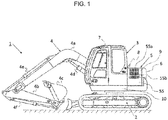
- Fig. 1 is a side view of a minimal swing radius hydraulic excavator that is a representative example of a construction machine according to the present invention
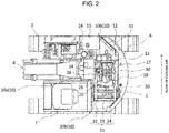
- Fig. 2 is a plan view that shows the inside of an engine room of the minimal swing radius hydraulic excavator shown in Fig. 1 .
- words of front, rear, left, and right are used based on the eye line of a worker riding and operating the minimal swing radius hydraulic excavator unless otherwise stated.
- a minimal swing radius hydraulic excavator (will be hereinafter referred to as a hydraulic excavator) 1 includes a travel base 2 and a revolving upperstructure 3 that is turnably attached to the upper side of the travel base 2.
- the minimal swing radius type means a type in which the turning diameter of the revolving upperstructure falls generally within the vehicle width of the travel base. For example, when the turning diameter of the revolving upperstructure of a hydraulic excavator falls within approximately 120% of the vehicle width, the hydraulic excavator is categorized as the minimal swing radius type.
- the revolving upperstructure 3 includes a revolving frame 10 that becomes a base, a cab 7 that is disposed on the front left side of the revolving frame 10, a front working mechanism (working device) 4 that is attached to the center in the front of the revolving frame 10 so as to be vertically rotatable, a counterweight 6 that is disposed behind the revolving frame 10, and an engine room 5 that is disposed between the front working mechanism 4 and the counterweight 6.
- the revolving frame 10 is configured of a rigid body that includes a center frame 10a of the center and side frames 10b in the left and right of the center frame 10a, and the front working mechanism 4 is attached to the distal end of the center frame 10a.
- the front working mechanism 4 is configured so as to include a boom 4a, an arm 4b, a bucket 4c, and hydraulic cylinders (actuators) 4d to 4f.
- the counterweight 6 is for achieving a weight balance with the front working mechanism 4, and is formed as a heavy object having an arc shape. Also, the counterweight 6 according to the present embodiment is disposed at a position close to the turning center so that the rear side of the revolving upperstructure 3 falls generally within the vehicle width of the travel base 2 even in the turning motion. Therefore, the space inside the engine room 5 becomes narrow compared with an ordinary hydraulic excavator.
- the engine room 5 is totally covered by an exterior cover 9.
- a door 55 is arranged through a hinge not illustrated, the door 55 opening/closing in a lateral direction.
- a suction port 55a and a knob 55b are arranged in the door 55, the suction port 55a sucking the external air (cooling air) into the engine room 5.
- the suction port 55a is arranged at the upper portion of the door 55, and has a shape of plural slits set elongated so that large foreign particles do not enter into the engine room 5 accompanying the external air. Also, it is configured to open the door 55 by pulling the knob 55b to execute a maintenance work and the like of the inside of the engine room 5.
- an outlet is formed which is for discharging the external air to the outside, the external air having been sucked from the suction port 55a into the engine room 5.
- an engine cover 41 and a maintenance cover 50 are arranged at the upper surface of the exterior cover 9, at the upper surface of the exterior cover 9, an engine cover 41 and a maintenance cover 50 are arranged (refer to Fig. 3 ).
- the reference sign 8 is a tail pipe for discharging an exhaust gas to the outside, the exhaust gas having been discharged from an engine 13 (refer to Fig. 2 ).
- the engine room 5 is configured to mainly include the engine 13, a heat exchanger unit 21 that exchanges heat with the engine 13, an exhaust gas post-treatment device 11 for reducing hazardous nitrogen oxide included in the exhaust gas from the engine 13 and degrading the nitrogen oxide to non-hazardous water and nitrogen, a hydraulic pump 12 that is driven by the engine 13 and supplies a hydraulic oil to the hydraulic cylinders 4d to 4f and the like of the front working mechanism 4, a compressor 19 for air conditioning of the inside of the cab 7, an alternator 25, a level gauge 26, a reserve tank 30, a hydraulic oil tank 16 that stores a hydraulic oil supplied to the hydraulic pump 12, and a fuel tank 15 that stores fuel of the engine 13.
- the engine 13 is mounted in a transverse state so as to extend in the lateral direction. Also, the engine 13 includes an intake manifold 17 that divides the air having been taken in to respective cylinders (not illustrated) and an exhaust manifold 18 that collects and discharges the exhaust gas from respective cylinders, and a turbocharger 14 is arranged on the flow out side of the exhaust manifold 18, the turbocharger 14 increasing the flow rate of the intake gas.
- a cooling fan 20 is attached to the left end of the engine 13.
- the cooling fan 20 sucks the external air into the exterior cover 9 through the suction port 55a because the cooling fan 20 is rotatavely driven using the engine 13 as a power source.
- the cooling air having been sucked into the exterior cover 9 cools various devices installed within the engine room 5, and is thereafter discharged to the atmospheric air from the outlet (not illustrated), openings 44 (refer to Fig. 3 ), and the like.
- the cooling air flows from the left to the right of the revolving upperstructure 3 (from the bottom to the top of Fig. 2 ).
- the heat exchanger unit 21 is disposed so as to face the flow of the cooling air.
- the heat exchanger unit 21 is configured so as to include a radiator 24 that cools cooling water for the engine 13, an oil cooler 22 that cools a hydraulic oil for operating the front working mechanism 4, and an intercooler 23 that cools the intake of the engine 13, and is disposed on the upstream side of the flow of the cooling air with respect to the cooling fan 20, namely on the left side of the cooling fan 20.
- the heat exchanger unit 21 is made detachable in a state the radiator 24 is integrated with the oil cooler 22 and the intercooler 23.
- each of the heat exchanger unit 21, the cooling fan 20, the engine 13, and the hydraulic pump 12 are disposed in this order from the upstream side to the downstream side of the flow of the cooling air, and the reserve tank 30 is arranged above the substantial center of the engine 13 as shown by the hatched line in Fig. 2 , the reserve tank 30 being for storing the cooling water of the engine 13.
- Fig. 3 is an external perspective view of the engine cover 41 and the maintenance cover 50. As shown in Fig. 3 , the engine cover 41 and the maintenance cover 50 are disposed so as to be arrayed in the lateral direction.
- the maintenance cover 50 is a plate in which a number of ventilation holes 51 are arranged on the left side and a knob 52 is arranged on the right side, and the maintenance cover 50 is attached to the upper portion of the exterior cover 9 through a hinge 53. A worker holds the knob 52 to open/close the maintenance cover 50 in the L-direction and R-direction of Fig. 3 . Also, when the maintenance cover 50 is opened, it becomes possible to draw out the heat exchanger unit 21.
- the engine cover 41 is a plate in which a discharge port 42 is arranged on the left side and a protrusion portion 43 is arranged on the right side respectively and a knob 46 is arranged on the front side, and the engine cover 41 is attached to the upper portion of the exterior cover 9 through a hinge 45. A worker holds the knob 56 to open/close the engine cover 41 in the X-direction and Y-direction of Fig. 3 .
- the protrusion portion 43 is formed into a generally truncated quadrangular pyramid, and the three openings 44 are arranged at the side surface that is an inclined surface on the right side. Although it will be described in detail below, the openings 44 are for emitting the cooling air having been taken in to the inside of the engine room 5 to the atmospheric air. Also, the reserve tank 30 is disposed below the protrusion portion 43. In other words, the protrusion portion 43 protrudes in order to cover the top portion of the reserve tank 30.
- a maintenance space A (refer to Figs. 4 to 6 ) described below is exposed, various devices within the engine room 5 become accessible, and visual confirmation of the level gauge 26 and the like also can be executed.
- Fig. 4 is a configuration drawing when an essential portion including the engine 13 inside the engine room 5 is viewed from obliquely above in the right
- Fig. 5 is a configuration drawing when an essential portion including the engine 13 inside the engine room 5 is viewed from the rear
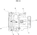
- Fig. 6 is a configuration drawing when an essential portion including the engine 13 inside the engine room 5 is viewed from the top.
- a front side grilled compartment frame 31, a rear side grilled compartment frame 32, and an engine upper right side grilled compartment frame 34, and an engine upper left side grilled compartment frame 35 are arranged around the engine 13.
- the engine upper right side grilled compartment frame 34 is formed into a generally reverse L-shape by an engine upper right side grilled compartment first frame 34a and an engine upper right side grilled compartment second frame 34b, the engine upper right side grilled compartment first frame 34a extending upward from a side frame 10b, the engine upper right side grilled compartment second frame 34b extending horizontally forward from the upper end of the engine upper right side grilled compartment first frame 34a.
- the rear side grilled compartment frame 32 works as a bridge between the upper portion of a fan shroud 40 and the upper ends of the engine upper right side grilled compartment first frame 34a, the fan shroud 40 storing the cooling fan 20, and the rear side grilled compartment frame 32 is arranged on the rear side of the front side grilled compartment frame 31 at a same height and to be generally parallel.
- the engine upper left side grilled compartment frame 35 is arranged on the left side of the engine upper right side grilled compartment second frame 34b at a same height and to be generally parallel.
- a bracket 33 is arranged so as to work as a bridge between the engine upper left side grilled compartment frame 35 and the engine upper right side grilled compartment second frame 34b.
- the reserve tank 30 is attached to this bracket 33.
- the reserve tank 30 is positioned generally in the center in the lateral direction and above of the engine 13. To be more specific, the reserve tank 30 is disposed at a height position H2 that is higher than a height position HI of the radiator 24 of the heat exchanger unit 21 from the side frame 10b. Also, it is configured that the protrusion portion 43 of the engine cover 41 covers the upper portion of this reserve tank 30. When the upper portion of the reserve tank 30 is covered by the protrusion portion 43, the openings 44 of the protrusion portion 43 come to be positioned in the vicinity of the reserve tank 30 and on the downstream side of the flow of the cooling air. In other words, the reserve tank 30 is disposed at a position that is located generally right above the engine 13, faces the openings 44 of the protrusion portion 43, and is positioned on the upstream side of the flow of the cooling air with respect to the openings 44.
- the maintenance space A is formed at the left upper portion of the engine 13.
- This maintenance space A is a space required, for example, for a worker to visually confirm the liquid surface of the level gauge 26 (refer to Fig. 2 ), to blow air to the cooling fan 20 to clean the dust and the like attached to the cooling fan 20, and to inspect the tension of a belt not illustrated. Therefore, in the present embodiment, the reserve tank 30 is disposed at a position escaping this maintenance space A. Accordingly, in the present embodiment, there is no event that the reserve tank 30 becomes an encumbrance to the maintenance work.
- Fig. 5 the cooling air is sucked from the left side and is discharged to the right side by the cooling fan 20. At this time, the cooling air flows also to the direction of an arrow F of Fig. 5 because of the openings 44 arranged in the protrusion portion 43 of the engine cover 41. Since the reserve tank 30 is positioned on the route of the flow of the cooling air, the reserve tank 30 is directly cooled constantly by the cooling air. Therefore, the inside of the reserve tank 30 is prevented from becoming hot in the inside of the engine room 5.
- the reserve tank 30 is hardly affected by the heat of the engine 13, and the temperature rise of the cooling water inside the reserve tank 30 is suppressed. Also, because the reserve tank 30 is disposed at a position above the engine 13 and escaping the maintenance space A, the reserve tank 30 does not become an encumbrance to the maintenance work when the maintenance work of the inside of the engine room 5 is executed.
- the reserve tank 30 is disposed at a position higher than the radiator 24, water supply from the reserve tank 30 to the radiator 24 becomes excellent.
- the protrusion portion 43 is formed into a generally truncated quadrangular pyramid shape of a degree capable of covering the upper portion of the reserve tank 30, such effect also can be exerted that the protrusion portion 43 hardly hinders rearward visibility of a worker riding the cab 7.
Landscapes
- Engineering & Computer Science (AREA)
- Mechanical Engineering (AREA)
- Mining & Mineral Resources (AREA)
- Civil Engineering (AREA)
- General Engineering & Computer Science (AREA)
- Structural Engineering (AREA)
- Combustion & Propulsion (AREA)
- Transportation (AREA)
- Chemical & Material Sciences (AREA)
- Life Sciences & Earth Sciences (AREA)
- Sustainable Development (AREA)
- Sustainable Energy (AREA)
- Component Parts Of Construction Machinery (AREA)
Abstract
Description
- The present invention relates to a construction machine in which a reserve tank for supplying water to a radiator is included and the turning radius of the rear portion of a revolving upperstructure is made small.
- As an example of the construction machine including a reserve tank for supplying water to a radiator, PATENT LITERATURE 1 is publicly known. In PATENT LITERATURE 1, such configuration is described that "an engine, a cooling fan connected to the engine, and a radiator disposed forward of the cooling fan are stored inside a revolving upperstructure, and a reservoir tank of the radiator is disposed right above a shroud of the cooling fan" (refer to the abstract).
- PATENT LITERATURE 1:
JP-A No. H11-190046 - According to PATENT LITERATURE 1, there are such problems that there is almost no movement of the air around the reservoir tank and the reservoir tank is liable to be seriously affected by the heat due to heat generation of the engine because the reservoir tank is disposed at the upper portion of the shroud of the cooling fan, and, when the engine is stopped, the reservoir tank is liable to be thermally affected by heat generation of the engine because there is no flow of the air.
- The present invention has been achieved in view of the circumstance described above, and its object is to provide a construction machine having such structure that a reserve tank is hardly affected by the heat of an engine.
- In order to achieve the object described above, according to the present invention, there is provided a construction machine including a travel base and a revolving upperstructure that is turnably attached to the travel base and includes a working device in the front, a counterweight in the rear, and an engine room between the working device and the counterweight, in which the engine room is totally covered by an exterior cover that includes an opening at the upper surface, and includes an engine, a radiator, a cooling fan, and a reserve tank in the inside of the engine room, the cooling fan sucking external air and cooling the radiator, the reserve tank storing cooling water of the engine, a flow of air inside the engine room is formed so that external air sucked into the engine room by the cooling fan is discharged from the opening, and the reserve tank is disposed at a position above the engine and facing the opening and a position on the upstream side of the flow of the air with respect to the opening.
- According to the present invention, the reserve tank is hardly affected by the heat of the engine. Also, problems, configurations, and effects other than the above will be clarified by explanation of embodiments below.
-
- [
Fig. 1] Fig. 1 is a side view of a minimal swing radius hydraulic excavator according to an embodiment of the present invention. - [
Fig. 2] Fig. 2 is a plan view that shows the inside of an engine room of the minimal swing radius hydraulic excavator shown inFig. 1 . - [
Fig. 3] Fig. 3 is an external perspective view of an engine cover and a maintenance cover of the engine room. - [
Fig. 4] Fig. 4 is a configuration drawing when an essential portion including an engine inside the engine room is viewed from obliquely above in the right. - [
Fig. 5] Fig. 5 is a configuration drawing when an essential portion including the engine inside the engine room is viewed from the rear. - [
Fig. 6] Fig. 6 is a configuration drawing when an essential portion including the engine inside the engine room is viewed from the top. - Embodiments of a construction machine according to the present invention will be explained using the drawings.
Fig. 1 is a side view of a minimal swing radius hydraulic excavator that is a representative example of a construction machine according to the present invention, andFig. 2 is a plan view that shows the inside of an engine room of the minimal swing radius hydraulic excavator shown inFig. 1 . Also, in the explanation below, words of front, rear, left, and right are used based on the eye line of a worker riding and operating the minimal swing radius hydraulic excavator unless otherwise stated. - As shown in
Fig. 1 , a minimal swing radius hydraulic excavator (will be hereinafter referred to as a hydraulic excavator) 1 includes atravel base 2 and a revolvingupperstructure 3 that is turnably attached to the upper side of thetravel base 2. Here, the minimal swing radius type means a type in which the turning diameter of the revolving upperstructure falls generally within the vehicle width of the travel base. For example, when the turning diameter of the revolving upperstructure of a hydraulic excavator falls within approximately 120% of the vehicle width, the hydraulic excavator is categorized as the minimal swing radius type. - The revolving
upperstructure 3 includes a revolvingframe 10 that becomes a base, acab 7 that is disposed on the front left side of the revolvingframe 10, a front working mechanism (working device) 4 that is attached to the center in the front of the revolvingframe 10 so as to be vertically rotatable, acounterweight 6 that is disposed behind the revolvingframe 10, and anengine room 5 that is disposed between thefront working mechanism 4 and thecounterweight 6. - As shown in
Fig. 2 , the revolvingframe 10 is configured of a rigid body that includes acenter frame 10a of the center andside frames 10b in the left and right of thecenter frame 10a, and thefront working mechanism 4 is attached to the distal end of thecenter frame 10a. - As shown in
Fig. 1 , thefront working mechanism 4 is configured so as to include aboom 4a, anarm 4b, a bucket 4c, and hydraulic cylinders (actuators) 4d to 4f. Thecounterweight 6 is for achieving a weight balance with thefront working mechanism 4, and is formed as a heavy object having an arc shape. Also, thecounterweight 6 according to the present embodiment is disposed at a position close to the turning center so that the rear side of the revolvingupperstructure 3 falls generally within the vehicle width of thetravel base 2 even in the turning motion. Therefore, the space inside theengine room 5 becomes narrow compared with an ordinary hydraulic excavator. - The
engine room 5 is totally covered by anexterior cover 9. On the left side of theexterior cover 9, adoor 55 is arranged through a hinge not illustrated, thedoor 55 opening/closing in a lateral direction. Asuction port 55a and aknob 55b are arranged in thedoor 55, thesuction port 55a sucking the external air (cooling air) into theengine room 5. - The
suction port 55a is arranged at the upper portion of thedoor 55, and has a shape of plural slits set elongated so that large foreign particles do not enter into theengine room 5 accompanying the external air. Also, it is configured to open thedoor 55 by pulling theknob 55b to execute a maintenance work and the like of the inside of theengine room 5. - Although it is not illustrated, on the right side of the
exterior cover 9 of theengine room 5, an outlet is formed which is for discharging the external air to the outside, the external air having been sucked from thesuction port 55a into theengine room 5. Further, although it will be described below in detail, at the upper surface of theexterior cover 9, anengine cover 41 and amaintenance cover 50 are arranged (refer toFig. 3 ). Also, thereference sign 8 is a tail pipe for discharging an exhaust gas to the outside, the exhaust gas having been discharged from an engine 13 (refer toFig. 2 ). - Next, the internal configuration of the
engine room 5 will be explained. As shown inFig. 2 , theengine room 5 is configured to mainly include theengine 13, aheat exchanger unit 21 that exchanges heat with theengine 13, an exhaustgas post-treatment device 11 for reducing hazardous nitrogen oxide included in the exhaust gas from theengine 13 and degrading the nitrogen oxide to non-hazardous water and nitrogen, ahydraulic pump 12 that is driven by theengine 13 and supplies a hydraulic oil to thehydraulic cylinders 4d to 4f and the like of thefront working mechanism 4, acompressor 19 for air conditioning of the inside of thecab 7, analternator 25, alevel gauge 26, areserve tank 30, ahydraulic oil tank 16 that stores a hydraulic oil supplied to thehydraulic pump 12, and afuel tank 15 that stores fuel of theengine 13. - The
engine 13 is mounted in a transverse state so as to extend in the lateral direction. Also, theengine 13 includes anintake manifold 17 that divides the air having been taken in to respective cylinders (not illustrated) and anexhaust manifold 18 that collects and discharges the exhaust gas from respective cylinders, and aturbocharger 14 is arranged on the flow out side of theexhaust manifold 18, theturbocharger 14 increasing the flow rate of the intake gas. - Also, to the left end of the
engine 13, acooling fan 20 is attached. Thecooling fan 20 sucks the external air into theexterior cover 9 through thesuction port 55a because thecooling fan 20 is rotatavely driven using theengine 13 as a power source. The cooling air having been sucked into theexterior cover 9 cools various devices installed within theengine room 5, and is thereafter discharged to the atmospheric air from the outlet (not illustrated), openings 44 (refer toFig. 3 ), and the like. In other words, in the present embodiment, the cooling air flows from the left to the right of the revolving upperstructure 3 (from the bottom to the top ofFig. 2 ). Also, theheat exchanger unit 21 is disposed so as to face the flow of the cooling air. - The
heat exchanger unit 21 is configured so as to include aradiator 24 that cools cooling water for theengine 13, anoil cooler 22 that cools a hydraulic oil for operating thefront working mechanism 4, and anintercooler 23 that cools the intake of theengine 13, and is disposed on the upstream side of the flow of the cooling air with respect to thecooling fan 20, namely on the left side of thecooling fan 20. Considering the maintainability, theheat exchanger unit 21 is made detachable in a state theradiator 24 is integrated with theoil cooler 22 and theintercooler 23. - Thus, in the inside of the
engine room 5, each of theheat exchanger unit 21, thecooling fan 20, theengine 13, and thehydraulic pump 12 are disposed in this order from the upstream side to the downstream side of the flow of the cooling air, and thereserve tank 30 is arranged above the substantial center of theengine 13 as shown by the hatched line inFig. 2 , thereserve tank 30 being for storing the cooling water of theengine 13. - Next, the details of the
engine cover 41 and themaintenance cover 50 will be explained, theengine cover 41 and themaintenance cover 50 being attached to the upper portion of theexterior cover 9.Fig. 3 is an external perspective view of theengine cover 41 and themaintenance cover 50. As shown inFig. 3 , theengine cover 41 and themaintenance cover 50 are disposed so as to be arrayed in the lateral direction. - The
maintenance cover 50 is a plate in which a number ofventilation holes 51 are arranged on the left side and aknob 52 is arranged on the right side, and themaintenance cover 50 is attached to the upper portion of theexterior cover 9 through ahinge 53. A worker holds theknob 52 to open/close themaintenance cover 50 in the L-direction and R-direction ofFig. 3 . Also, when themaintenance cover 50 is opened, it becomes possible to draw out theheat exchanger unit 21. - The
engine cover 41 is a plate in which adischarge port 42 is arranged on the left side and aprotrusion portion 43 is arranged on the right side respectively and aknob 46 is arranged on the front side, and theengine cover 41 is attached to the upper portion of theexterior cover 9 through ahinge 45. A worker holds the knob 56 to open/close theengine cover 41 in the X-direction and Y-direction ofFig. 3 . - The
protrusion portion 43 is formed into a generally truncated quadrangular pyramid, and the threeopenings 44 are arranged at the side surface that is an inclined surface on the right side. Although it will be described in detail below, theopenings 44 are for emitting the cooling air having been taken in to the inside of theengine room 5 to the atmospheric air. Also, thereserve tank 30 is disposed below theprotrusion portion 43. In other words, theprotrusion portion 43 protrudes in order to cover the top portion of thereserve tank 30. - Also, when the
engine cover 41 is opened, a maintenance space A (refer toFigs. 4 to 6 ) described below is exposed, various devices within theengine room 5 become accessible, and visual confirmation of thelevel gauge 26 and the like also can be executed. - Next, the positional relation of the engine and the reserve tank will be explained using
Fig. 4 to Fig. 6 .Fig. 4 is a configuration drawing when an essential portion including theengine 13 inside theengine room 5 is viewed from obliquely above in the right,Fig. 5 is a configuration drawing when an essential portion including theengine 13 inside theengine room 5 is viewed from the rear, andFig. 6 is a configuration drawing when an essential portion including theengine 13 inside theengine room 5 is viewed from the top. - As shown in
Fig. 4 to Fig. 6 , plural frames are arranged around theengine 13. In concrete terms, a front side grilledcompartment frame 31, a rear side grilledcompartment frame 32, and an engine upper right side grilledcompartment frame 34, and an engine upper left side grilledcompartment frame 35 are arranged around theengine 13. The engine upper right side grilledcompartment frame 34 is formed into a generally reverse L-shape by an engine upper right side grilled compartmentfirst frame 34a and an engine upper right side grilled compartmentsecond frame 34b, the engine upper right side grilled compartmentfirst frame 34a extending upward from aside frame 10b, the engine upper right side grilled compartmentsecond frame 34b extending horizontally forward from the upper end of the engine upper right side grilled compartmentfirst frame 34a. - The rear side grilled
compartment frame 32 works as a bridge between the upper portion of afan shroud 40 and the upper ends of the engine upper right side grilled compartmentfirst frame 34a, thefan shroud 40 storing the coolingfan 20, and the rear side grilledcompartment frame 32 is arranged on the rear side of the front side grilledcompartment frame 31 at a same height and to be generally parallel. The engine upper left side grilledcompartment frame 35 is arranged on the left side of the engine upper right side grilled compartmentsecond frame 34b at a same height and to be generally parallel. Also, abracket 33 is arranged so as to work as a bridge between the engine upper left side grilledcompartment frame 35 and the engine upper right side grilled compartmentsecond frame 34b. Thereserve tank 30 is attached to thisbracket 33. - The
reserve tank 30 is positioned generally in the center in the lateral direction and above of theengine 13. To be more specific, thereserve tank 30 is disposed at a height position H2 that is higher than a height position HI of theradiator 24 of theheat exchanger unit 21 from theside frame 10b. Also, it is configured that theprotrusion portion 43 of theengine cover 41 covers the upper portion of thisreserve tank 30. When the upper portion of thereserve tank 30 is covered by theprotrusion portion 43, theopenings 44 of theprotrusion portion 43 come to be positioned in the vicinity of thereserve tank 30 and on the downstream side of the flow of the cooling air. In other words, thereserve tank 30 is disposed at a position that is located generally right above theengine 13, faces theopenings 44 of theprotrusion portion 43, and is positioned on the upstream side of the flow of the cooling air with respect to theopenings 44. - As shown in
Fig. 4 to Fig. 6 , the maintenance space A is formed at the left upper portion of theengine 13. This maintenance space A is a space required, for example, for a worker to visually confirm the liquid surface of the level gauge 26 (refer toFig. 2 ), to blow air to the coolingfan 20 to clean the dust and the like attached to the coolingfan 20, and to inspect the tension of a belt not illustrated. Therefore, in the present embodiment, thereserve tank 30 is disposed at a position escaping this maintenance space A. Accordingly, in the present embodiment, there is no event that thereserve tank 30 becomes an encumbrance to the maintenance work. - Next, the flow of the cooling air within the
engine room 5 will be explained usingFig. 5 . As shown inFig. 5 , the cooling air is sucked from the left side and is discharged to the right side by the coolingfan 20. At this time, the cooling air flows also to the direction of an arrow F ofFig. 5 because of theopenings 44 arranged in theprotrusion portion 43 of theengine cover 41. Since thereserve tank 30 is positioned on the route of the flow of the cooling air, thereserve tank 30 is directly cooled constantly by the cooling air. Therefore, the inside of thereserve tank 30 is prevented from becoming hot in the inside of theengine room 5. - As explained above, according to the present embodiment, because it is configured that the cooling air directly hits the
reserve tank 30, thereserve tank 30 is hardly affected by the heat of theengine 13, and the temperature rise of the cooling water inside thereserve tank 30 is suppressed. Also, because thereserve tank 30 is disposed at a position above theengine 13 and escaping the maintenance space A, thereserve tank 30 does not become an encumbrance to the maintenance work when the maintenance work of the inside of theengine room 5 is executed. - Also, because the
reserve tank 30 is disposed at a position higher than theradiator 24, water supply from thereserve tank 30 to theradiator 24 becomes excellent. Further, because theprotrusion portion 43 is formed into a generally truncated quadrangular pyramid shape of a degree capable of covering the upper portion of thereserve tank 30, such effect also can be exerted that theprotrusion portion 43 hardly hinders rearward visibility of a worker riding thecab 7. - Also, the embodiments described above are only exemplifications for explanation of the present invention, and are not intended to limit the scope of the present invention only to these embodiments. A person with an ordinary skill in the art can implement the present invention with other various aspects without departing from the gist of the present invention.
-
- 1 ... Minimal swing radius type hydraulic excavator (construction machine)
- 2 ... Travel base
- 3 ... Revolving upperstructure
- 4 ... Front working mechanism (working device)
- 5 ... Engine room
- 6 ... Counterweight
- 9 ... Exterior cover
- 13 ... Engine
- 24 ... Radiator
- 30 ... Reserve tank
- 41 ... Engine cover (cover)
- 43 ... Protrusion portion
- 44 ... Opening
- A ... Maintenance space
Claims (3)
- A construction machine, comprising:a travel base; anda revolving upperstructure that is turnably attached to the travel base and includes a working device in the front, a counterweight in the rear, and an engine room between the working device and the counterweight,wherein the engine room is totally covered by an exterior cover that includes an opening at the upper surface, and includes an engine, a radiator, a cooling fan, and a reserve tank in the inside of the engine room, the cooling fan sucking external air and cooling the radiator, the reserve tank storing cooling water of the engine,
a flow of air inside the engine room is formed so that external air sucked into the engine room by the cooling fan is discharged from the opening, and
the reserve tank is disposed at a position above the engine and facing the opening and a position on the upstream side of the flow of the air with respect to the opening. - The construction machine according to claim 1,
wherein an openable/closable cover is arranged at the upper surface of the exterior cover,
a protrusion portion is arranged in the cover, the protrusion portion protruding upward for covering the upper portion of the reserve tank, and
the opening is arranged in the protrusion portion. - The construction machine according to claim 2,
wherein the radiator, the cooling fan, and the engine are disposed in this order from the upstream side to the downstream side of the flow of the air,
a space for maintenance is formed between the cooling fan and the engine, and
the reserve tank is disposed at a position escaping the space for maintenance and a position above the radiator.
Applications Claiming Priority (1)
| Application Number | Priority Date | Filing Date | Title |
|---|---|---|---|
| PCT/JP2016/057682 WO2017154188A1 (en) | 2016-03-10 | 2016-03-10 | Construction machine |
Publications (3)
| Publication Number | Publication Date |
|---|---|
| EP3428346A1 true EP3428346A1 (en) | 2019-01-16 |
| EP3428346A4 EP3428346A4 (en) | 2019-11-20 |
| EP3428346B1 EP3428346B1 (en) | 2020-12-23 |
Family
ID=59789211
Family Applications (1)
| Application Number | Title | Priority Date | Filing Date |
|---|---|---|---|
| EP16893515.3A Active EP3428346B1 (en) | 2016-03-10 | 2016-03-10 | Construction machine |
Country Status (5)
| Country | Link |
|---|---|
| US (1) | US10640949B2 (en) |
| EP (1) | EP3428346B1 (en) |
| JP (1) | JP6527287B2 (en) |
| CN (1) | CN107923141B (en) |
| WO (1) | WO2017154188A1 (en) |
Families Citing this family (11)
| Publication number | Priority date | Publication date | Assignee | Title |
|---|---|---|---|---|
| CN106956587B (en) * | 2017-01-20 | 2020-03-20 | 徐工集团工程机械有限公司 | Vehicle power compartment and engineering vehicle with same |
| JP6982364B2 (en) * | 2017-08-24 | 2021-12-17 | キャタピラー エス エー アール エル | Hydraulic excavator |
| USD1020926S1 (en) * | 2018-12-12 | 2024-04-02 | Bruder Spielwaren Gmbh + Co. Kg | Toy |
| JP6922960B2 (en) * | 2019-09-26 | 2021-08-18 | コベルコ建機株式会社 | Construction machinery |
| JP7153627B2 (en) * | 2019-10-31 | 2022-10-14 | 日立建機株式会社 | Work machine and perimeter monitoring system |
| JP7329434B2 (en) * | 2019-12-23 | 2023-08-18 | 株式会社小松製作所 | working machine |
| JP2021116555A (en) * | 2020-01-23 | 2021-08-10 | キャタピラー エス エー アール エル | Working machine |
| US20240141615A1 (en) * | 2021-06-30 | 2024-05-02 | Hitachi Construction Machinery Co., Ltd. | Construction Machine |
| US12077938B2 (en) * | 2021-10-12 | 2024-09-03 | Caterpillar Inc. | Secondary control system and method for mounting with service orientation |
| JP7710390B2 (en) * | 2022-02-28 | 2025-07-18 | ヤンマーホールディングス株式会社 | Work Machine |
| KR20250004855A (en) | 2022-08-30 | 2025-01-08 | 가부시키가이샤 히다치 겡키 티에라 | Electric construction machinery |
Family Cites Families (29)
| Publication number | Priority date | Publication date | Assignee | Title |
|---|---|---|---|---|
| US4862981A (en) * | 1984-12-24 | 1989-09-05 | Kawasaki Jukogyo Kabushiki Kaisha | Internal combustion engine and devices employing same |
| US5329889A (en) * | 1993-11-22 | 1994-07-19 | Molmec, Inc. | Degas tank for engine cooling system |
| JPH11190046A (en) | 1997-12-25 | 1999-07-13 | Yutani Heavy Ind Ltd | Hydraulic shovel |
| JP2001123836A (en) * | 1999-10-26 | 2001-05-08 | Hitachi Constr Mach Co Ltd | Engine cooling system for construction machinery |
| CN1201055C (en) * | 2000-12-01 | 2005-05-11 | 日立建机株式会社 | Construction machinery |
| JP4280142B2 (en) * | 2003-10-17 | 2009-06-17 | 川崎重工業株式会社 | Vertical liquid cooling engine |
| JP4328221B2 (en) * | 2004-01-21 | 2009-09-09 | キャタピラージャパン株式会社 | Construction machine cooling system |
| JP4226505B2 (en) * | 2004-03-29 | 2009-02-18 | 株式会社クボタ | Swivel work machine |
| CN100482901C (en) | 2004-03-29 | 2009-04-29 | 株式会社久保田 | Swiveling utility machine having swivel deck |
| US7107943B2 (en) * | 2004-09-15 | 2006-09-19 | Denko Kabushiki Kaisha | Engine-driven operating machine |
| JP2007016752A (en) * | 2005-07-11 | 2007-01-25 | Hitachi Constr Mach Co Ltd | Engine compartment for construction machine |
| US20070044938A1 (en) * | 2005-08-26 | 2007-03-01 | Farley Mary L | Dual surge tank for vehicle cooling system |
| JP4463221B2 (en) * | 2006-03-01 | 2010-05-19 | 株式会社クボタ | Swivel work machine |
| JP5321910B2 (en) * | 2009-09-24 | 2013-10-23 | スズキ株式会社 | Hybrid vehicle cooling system |
| WO2011102042A1 (en) * | 2010-02-22 | 2011-08-25 | 日立建機株式会社 | Electrical construction machine |
| JP5467525B2 (en) * | 2010-07-28 | 2014-04-09 | スズキ株式会社 | Support structure for vehicle coolant reserve tank |
| DE112011104946B4 (en) * | 2011-02-23 | 2018-10-11 | Suzuki Motor Corporation | Cooling device for hybrid vehicles |
| JP5864202B2 (en) * | 2011-10-18 | 2016-02-17 | 株式会社Kcm | Industrial vehicle |
| JP5883278B2 (en) * | 2011-11-29 | 2016-03-09 | 日立建機株式会社 | Construction machinery |
| JP5917383B2 (en) * | 2012-12-11 | 2016-05-11 | 日立建機株式会社 | Construction machinery |
| US8919486B2 (en) * | 2013-02-15 | 2014-12-30 | Komatsu Ltd. | Hydraulic excavator |
| DE112013000161C5 (en) * | 2013-03-15 | 2023-03-16 | Komatsu Ltd. | Exhaust aftertreatment unit and a construction vehicle containing it |
| US9238901B2 (en) * | 2013-08-09 | 2016-01-19 | Komatsu Ltd. | Supporting mechanism, exhaust treatment unit, and wheel loader |
| WO2015045106A1 (en) * | 2013-09-27 | 2015-04-02 | 株式会社小松製作所 | Work vehicle |
| JP6009480B2 (en) * | 2014-03-06 | 2016-10-19 | 日立建機株式会社 | Cooling fan control device for construction machinery |
| JP6371630B2 (en) * | 2014-08-05 | 2018-08-08 | ヤンマー株式会社 | Engine system |
| CN104428470B (en) * | 2014-08-25 | 2018-08-24 | 株式会社小松制作所 | bulldozer |
| JP6454142B2 (en) * | 2014-11-28 | 2019-01-16 | 日立建機株式会社 | Construction machinery |
| JP6560587B2 (en) * | 2015-10-06 | 2019-08-14 | 日立建機株式会社 | Construction machinery |
-
2016
- 2016-03-10 JP JP2018503956A patent/JP6527287B2/en active Active
- 2016-03-10 US US15/752,747 patent/US10640949B2/en active Active
- 2016-03-10 CN CN201680048568.8A patent/CN107923141B/en active Active
- 2016-03-10 EP EP16893515.3A patent/EP3428346B1/en active Active
- 2016-03-10 WO PCT/JP2016/057682 patent/WO2017154188A1/en not_active Ceased
Also Published As
| Publication number | Publication date |
|---|---|
| WO2017154188A1 (en) | 2017-09-14 |
| CN107923141A (en) | 2018-04-17 |
| US20180238020A1 (en) | 2018-08-23 |
| EP3428346B1 (en) | 2020-12-23 |
| JPWO2017154188A1 (en) | 2018-05-31 |
| EP3428346A4 (en) | 2019-11-20 |
| US10640949B2 (en) | 2020-05-05 |
| JP6527287B2 (en) | 2019-06-05 |
| CN107923141B (en) | 2020-06-12 |
Similar Documents
| Publication | Publication Date | Title |
|---|---|---|
| EP3428346B1 (en) | Construction machine | |
| KR102035212B1 (en) | Construction machinery | |
| US8544584B2 (en) | Construction vehicle | |
| JP5649463B2 (en) | Construction machinery | |
| KR101739308B1 (en) | Hydraulic shovel | |
| WO2007004327A1 (en) | Construction machine | |
| JP2011025896A (en) | Dust-proof net arrangement structure | |
| KR20170035975A (en) | Construction machine | |
| JP2004352089A (en) | Slewing working machine | |
| JP2010229744A (en) | Dustproof device for construction machinery | |
| JPWO2014088033A1 (en) | Construction machinery | |
| JP5917383B2 (en) | Construction machinery | |
| EP1788159A1 (en) | Slewing type working machine | |
| JP2013104276A (en) | Filter device for construction machine | |
| JP5699066B2 (en) | Construction machinery | |
| JP6810082B2 (en) | Construction machinery | |
| JP2012172343A (en) | Engine room for construction machine | |
| CN105612292B (en) | Arrangement of components of a cooling unit in a construction machine | |
| EP4249688A1 (en) | Construction machine | |
| JP2006037661A (en) | Heat exchange device | |
| JP2024090131A (en) | Excavator | |
| JP2013104345A (en) | Cooling device of construction machine | |
| JP2006038412A (en) | Heat exchanger | |
| JP2007217919A (en) | Swivel work machine |
Legal Events
| Date | Code | Title | Description |
|---|---|---|---|
| STAA | Information on the status of an ep patent application or granted ep patent |
Free format text: STATUS: THE INTERNATIONAL PUBLICATION HAS BEEN MADE |
|
| PUAI | Public reference made under article 153(3) epc to a published international application that has entered the european phase |
Free format text: ORIGINAL CODE: 0009012 |
|
| STAA | Information on the status of an ep patent application or granted ep patent |
Free format text: STATUS: REQUEST FOR EXAMINATION WAS MADE |
|
| 17P | Request for examination filed |
Effective date: 20180305 |
|
| AK | Designated contracting states |
Kind code of ref document: A1 Designated state(s): AL AT BE BG CH CY CZ DE DK EE ES FI FR GB GR HR HU IE IS IT LI LT LU LV MC MK MT NL NO PL PT RO RS SE SI SK SM TR |
|
| AX | Request for extension of the european patent |
Extension state: BA ME |
|
| DAV | Request for validation of the european patent (deleted) | ||
| DAX | Request for extension of the european patent (deleted) | ||
| A4 | Supplementary search report drawn up and despatched |
Effective date: 20191022 |
|
| RIC1 | Information provided on ipc code assigned before grant |
Ipc: E02F 9/00 20060101AFI20191016BHEP |
|
| GRAP | Despatch of communication of intention to grant a patent |
Free format text: ORIGINAL CODE: EPIDOSNIGR1 |
|
| STAA | Information on the status of an ep patent application or granted ep patent |
Free format text: STATUS: GRANT OF PATENT IS INTENDED |
|
| INTG | Intention to grant announced |
Effective date: 20200929 |
|
| RIN1 | Information on inventor provided before grant (corrected) |
Inventor name: HIRASAWA, SHIGERU Inventor name: MIZOGUCHI, KAZUHIKO Inventor name: HIBIYA, TAKESHI Inventor name: KANNO, TOSHIKAZU |
|
| GRAS | Grant fee paid |
Free format text: ORIGINAL CODE: EPIDOSNIGR3 |
|
| GRAA | (expected) grant |
Free format text: ORIGINAL CODE: 0009210 |
|
| STAA | Information on the status of an ep patent application or granted ep patent |
Free format text: STATUS: THE PATENT HAS BEEN GRANTED |
|
| AK | Designated contracting states |
Kind code of ref document: B1 Designated state(s): AL AT BE BG CH CY CZ DE DK EE ES FI FR GB GR HR HU IE IS IT LI LT LU LV MC MK MT NL NO PL PT RO RS SE SI SK SM TR |
|
| REG | Reference to a national code |
Ref country code: GB Ref legal event code: FG4D |
|
| REG | Reference to a national code |
Ref country code: DE Ref legal event code: R096 Ref document number: 602016050424 Country of ref document: DE |
|
| REG | Reference to a national code |
Ref country code: AT Ref legal event code: REF Ref document number: 1347858 Country of ref document: AT Kind code of ref document: T Effective date: 20210115 |
|
| REG | Reference to a national code |
Ref country code: IE Ref legal event code: FG4D |
|
| PG25 | Lapsed in a contracting state [announced via postgrant information from national office to epo] |
Ref country code: NO Free format text: LAPSE BECAUSE OF FAILURE TO SUBMIT A TRANSLATION OF THE DESCRIPTION OR TO PAY THE FEE WITHIN THE PRESCRIBED TIME-LIMIT Effective date: 20210323 Ref country code: RS Free format text: LAPSE BECAUSE OF FAILURE TO SUBMIT A TRANSLATION OF THE DESCRIPTION OR TO PAY THE FEE WITHIN THE PRESCRIBED TIME-LIMIT Effective date: 20201223 Ref country code: FI Free format text: LAPSE BECAUSE OF FAILURE TO SUBMIT A TRANSLATION OF THE DESCRIPTION OR TO PAY THE FEE WITHIN THE PRESCRIBED TIME-LIMIT Effective date: 20201223 Ref country code: GR Free format text: LAPSE BECAUSE OF FAILURE TO SUBMIT A TRANSLATION OF THE DESCRIPTION OR TO PAY THE FEE WITHIN THE PRESCRIBED TIME-LIMIT Effective date: 20210324 |
|
| REG | Reference to a national code |
Ref country code: AT Ref legal event code: MK05 Ref document number: 1347858 Country of ref document: AT Kind code of ref document: T Effective date: 20201223 |
|
| REG | Reference to a national code |
Ref country code: NL Ref legal event code: MP Effective date: 20201223 |
|
| PG25 | Lapsed in a contracting state [announced via postgrant information from national office to epo] |
Ref country code: BG Free format text: LAPSE BECAUSE OF FAILURE TO SUBMIT A TRANSLATION OF THE DESCRIPTION OR TO PAY THE FEE WITHIN THE PRESCRIBED TIME-LIMIT Effective date: 20210323 Ref country code: LV Free format text: LAPSE BECAUSE OF FAILURE TO SUBMIT A TRANSLATION OF THE DESCRIPTION OR TO PAY THE FEE WITHIN THE PRESCRIBED TIME-LIMIT Effective date: 20201223 Ref country code: SE Free format text: LAPSE BECAUSE OF FAILURE TO SUBMIT A TRANSLATION OF THE DESCRIPTION OR TO PAY THE FEE WITHIN THE PRESCRIBED TIME-LIMIT Effective date: 20201223 |
|
| PG25 | Lapsed in a contracting state [announced via postgrant information from national office to epo] |
Ref country code: HR Free format text: LAPSE BECAUSE OF FAILURE TO SUBMIT A TRANSLATION OF THE DESCRIPTION OR TO PAY THE FEE WITHIN THE PRESCRIBED TIME-LIMIT Effective date: 20201223 Ref country code: NL Free format text: LAPSE BECAUSE OF FAILURE TO SUBMIT A TRANSLATION OF THE DESCRIPTION OR TO PAY THE FEE WITHIN THE PRESCRIBED TIME-LIMIT Effective date: 20201223 |
|
| REG | Reference to a national code |
Ref country code: LT Ref legal event code: MG9D |
|
| PG25 | Lapsed in a contracting state [announced via postgrant information from national office to epo] |
Ref country code: SK Free format text: LAPSE BECAUSE OF FAILURE TO SUBMIT A TRANSLATION OF THE DESCRIPTION OR TO PAY THE FEE WITHIN THE PRESCRIBED TIME-LIMIT Effective date: 20201223 Ref country code: PT Free format text: LAPSE BECAUSE OF FAILURE TO SUBMIT A TRANSLATION OF THE DESCRIPTION OR TO PAY THE FEE WITHIN THE PRESCRIBED TIME-LIMIT Effective date: 20210423 Ref country code: RO Free format text: LAPSE BECAUSE OF FAILURE TO SUBMIT A TRANSLATION OF THE DESCRIPTION OR TO PAY THE FEE WITHIN THE PRESCRIBED TIME-LIMIT Effective date: 20201223 Ref country code: SM Free format text: LAPSE BECAUSE OF FAILURE TO SUBMIT A TRANSLATION OF THE DESCRIPTION OR TO PAY THE FEE WITHIN THE PRESCRIBED TIME-LIMIT Effective date: 20201223 Ref country code: LT Free format text: LAPSE BECAUSE OF FAILURE TO SUBMIT A TRANSLATION OF THE DESCRIPTION OR TO PAY THE FEE WITHIN THE PRESCRIBED TIME-LIMIT Effective date: 20201223 Ref country code: CZ Free format text: LAPSE BECAUSE OF FAILURE TO SUBMIT A TRANSLATION OF THE DESCRIPTION OR TO PAY THE FEE WITHIN THE PRESCRIBED TIME-LIMIT Effective date: 20201223 Ref country code: EE Free format text: LAPSE BECAUSE OF FAILURE TO SUBMIT A TRANSLATION OF THE DESCRIPTION OR TO PAY THE FEE WITHIN THE PRESCRIBED TIME-LIMIT Effective date: 20201223 |
|
| PG25 | Lapsed in a contracting state [announced via postgrant information from national office to epo] |
Ref country code: AT Free format text: LAPSE BECAUSE OF FAILURE TO SUBMIT A TRANSLATION OF THE DESCRIPTION OR TO PAY THE FEE WITHIN THE PRESCRIBED TIME-LIMIT Effective date: 20201223 Ref country code: PL Free format text: LAPSE BECAUSE OF FAILURE TO SUBMIT A TRANSLATION OF THE DESCRIPTION OR TO PAY THE FEE WITHIN THE PRESCRIBED TIME-LIMIT Effective date: 20201223 |
|
| REG | Reference to a national code |
Ref country code: DE Ref legal event code: R097 Ref document number: 602016050424 Country of ref document: DE |
|
| PG25 | Lapsed in a contracting state [announced via postgrant information from national office to epo] |
Ref country code: IS Free format text: LAPSE BECAUSE OF FAILURE TO SUBMIT A TRANSLATION OF THE DESCRIPTION OR TO PAY THE FEE WITHIN THE PRESCRIBED TIME-LIMIT Effective date: 20210423 |
|
| PG25 | Lapsed in a contracting state [announced via postgrant information from national office to epo] |
Ref country code: IT Free format text: LAPSE BECAUSE OF FAILURE TO SUBMIT A TRANSLATION OF THE DESCRIPTION OR TO PAY THE FEE WITHIN THE PRESCRIBED TIME-LIMIT Effective date: 20201223 Ref country code: MC Free format text: LAPSE BECAUSE OF FAILURE TO SUBMIT A TRANSLATION OF THE DESCRIPTION OR TO PAY THE FEE WITHIN THE PRESCRIBED TIME-LIMIT Effective date: 20201223 Ref country code: AL Free format text: LAPSE BECAUSE OF FAILURE TO SUBMIT A TRANSLATION OF THE DESCRIPTION OR TO PAY THE FEE WITHIN THE PRESCRIBED TIME-LIMIT Effective date: 20201223 |
|
| PLBE | No opposition filed within time limit |
Free format text: ORIGINAL CODE: 0009261 |
|
| REG | Reference to a national code |
Ref country code: CH Ref legal event code: PL |
|
| STAA | Information on the status of an ep patent application or granted ep patent |
Free format text: STATUS: NO OPPOSITION FILED WITHIN TIME LIMIT |
|
| PG25 | Lapsed in a contracting state [announced via postgrant information from national office to epo] |
Ref country code: DK Free format text: LAPSE BECAUSE OF FAILURE TO SUBMIT A TRANSLATION OF THE DESCRIPTION OR TO PAY THE FEE WITHIN THE PRESCRIBED TIME-LIMIT Effective date: 20201223 |
|
| 26N | No opposition filed |
Effective date: 20210924 |
|
| REG | Reference to a national code |
Ref country code: BE Ref legal event code: MM Effective date: 20210331 |
|
| PG25 | Lapsed in a contracting state [announced via postgrant information from national office to epo] |
Ref country code: LI Free format text: LAPSE BECAUSE OF NON-PAYMENT OF DUE FEES Effective date: 20210331 Ref country code: LU Free format text: LAPSE BECAUSE OF NON-PAYMENT OF DUE FEES Effective date: 20210310 Ref country code: CH Free format text: LAPSE BECAUSE OF NON-PAYMENT OF DUE FEES Effective date: 20210331 Ref country code: FR Free format text: LAPSE BECAUSE OF NON-PAYMENT OF DUE FEES Effective date: 20210331 Ref country code: IE Free format text: LAPSE BECAUSE OF NON-PAYMENT OF DUE FEES Effective date: 20210310 Ref country code: ES Free format text: LAPSE BECAUSE OF FAILURE TO SUBMIT A TRANSLATION OF THE DESCRIPTION OR TO PAY THE FEE WITHIN THE PRESCRIBED TIME-LIMIT Effective date: 20201223 |
|
| PG25 | Lapsed in a contracting state [announced via postgrant information from national office to epo] |
Ref country code: SI Free format text: LAPSE BECAUSE OF FAILURE TO SUBMIT A TRANSLATION OF THE DESCRIPTION OR TO PAY THE FEE WITHIN THE PRESCRIBED TIME-LIMIT Effective date: 20201223 |
|
| PG25 | Lapsed in a contracting state [announced via postgrant information from national office to epo] |
Ref country code: IS Free format text: LAPSE BECAUSE OF FAILURE TO SUBMIT A TRANSLATION OF THE DESCRIPTION OR TO PAY THE FEE WITHIN THE PRESCRIBED TIME-LIMIT Effective date: 20210423 |
|
| PG25 | Lapsed in a contracting state [announced via postgrant information from national office to epo] |
Ref country code: BE Free format text: LAPSE BECAUSE OF NON-PAYMENT OF DUE FEES Effective date: 20210331 |
|
| PG25 | Lapsed in a contracting state [announced via postgrant information from national office to epo] |
Ref country code: CY Free format text: LAPSE BECAUSE OF FAILURE TO SUBMIT A TRANSLATION OF THE DESCRIPTION OR TO PAY THE FEE WITHIN THE PRESCRIBED TIME-LIMIT Effective date: 20201223 |
|
| PG25 | Lapsed in a contracting state [announced via postgrant information from national office to epo] |
Ref country code: HU Free format text: LAPSE BECAUSE OF FAILURE TO SUBMIT A TRANSLATION OF THE DESCRIPTION OR TO PAY THE FEE WITHIN THE PRESCRIBED TIME-LIMIT; INVALID AB INITIO Effective date: 20160310 |
|
| PG25 | Lapsed in a contracting state [announced via postgrant information from national office to epo] |
Ref country code: MK Free format text: LAPSE BECAUSE OF FAILURE TO SUBMIT A TRANSLATION OF THE DESCRIPTION OR TO PAY THE FEE WITHIN THE PRESCRIBED TIME-LIMIT Effective date: 20201223 |
|
| PG25 | Lapsed in a contracting state [announced via postgrant information from national office to epo] |
Ref country code: TR Free format text: LAPSE BECAUSE OF FAILURE TO SUBMIT A TRANSLATION OF THE DESCRIPTION OR TO PAY THE FEE WITHIN THE PRESCRIBED TIME-LIMIT Effective date: 20201223 |
|
| PG25 | Lapsed in a contracting state [announced via postgrant information from national office to epo] |
Ref country code: MT Free format text: LAPSE BECAUSE OF FAILURE TO SUBMIT A TRANSLATION OF THE DESCRIPTION OR TO PAY THE FEE WITHIN THE PRESCRIBED TIME-LIMIT Effective date: 20201223 |
|
| PGFP | Annual fee paid to national office [announced via postgrant information from national office to epo] |
Ref country code: GB Payment date: 20260202 Year of fee payment: 11 |
|
| PGFP | Annual fee paid to national office [announced via postgrant information from national office to epo] |
Ref country code: DE Payment date: 20260128 Year of fee payment: 11 |